ss1002 2002 202rm user manual - textfiles.compdf.textfiles.com/manuals/starinmanuals/telex...
TRANSCRIPT

19350-7741-000 Rev A, 10/2002
User Instructions
Model SS-1002Single ChannelIntercom SpeakerStation
Model SS-2002Two ChannelIntercom SpeakerStation
Model SS-2002RMTwo ChannelRack MountIntercom SpeakerStation
Audiocom® Intercom Systems
2
FCC StatementThis equipment uses, and can radiate radio frequency energy that may cause interference to radio com-munications if not installed in accordance with this manual. The equipment has been tested and found tocomply with the limits of a Class A computing device pursuant to Subpart J, Part 15 of FCC Rules whichare designed to provide reasonable protection against such interference when operated in a commercialenvironment. Operation of this equipment in a residential area may cause interference which the user (athis own expense) will be required to correct.
This product meets Electromagnetic Compatibility Directive 89/336/EEC

3
Table of ContentsIntroduction............................................................................... 4
Description ................................................................................ 4
Features ..................................................................................... 4
Installation ................................................................................. 6Unpacking ..................................................................................................................................... 6Configuration Pre-check .............................................................................................................. 6DIP Switches .................................................................................................................................. 6Power-Up ..................................................................................................................................... 14Sidetone Adjustment................................................................................................................... 14
Operation................................................................................. 15Channel Select (SS-2002 & SS-2002RM Only) ........................................................................ 15Headset/Headphone/Speaker/Microphone Selection .............................................................. 15Receiving Calls ............................................................................................................................ 15Calling an Intercom Channel .................................................................................................... 15
Specifications ........................................................................... 16General ........................................................................................................................................ 16Dynamic-mic Headset/Handset ................................................................................................. 16Panel Microphone ....................................................................................................................... 16Intercom Channels, Balanced mode (SW1 set to BAL position) ............................................ 16Intercom Channels, Unbalanced mode (SW1 set to UNBAL position).................................. 16Speaker Output Power ............................................................................................................... 17Dimensions .................................................................................................................................. 17

4
IntroductionThank you for purchasing the Audiocom SS-1002/SS-2002/SS-2002RM Intercom Speaker Station. We hope the many designfeatures of this product will satisfy your intercommunication requirements for many years to come. To get the most out ofyour new intercom station, please take a few moments to look through this booklet before using the Intercom Speaker Stationfor the first time.
DescriptionThe Intercom Speaker Stations may be used with a headset, or with the built-in speaker and the panel microphone or an optionalgooseneck microphone. Another alternative is to use headphones and either the built-in panel microphone or an optional goose-neck microphone. As an alternative to a headset, a telephone style handset may also be used. The SS-1002 is a single-channelstation; the SS-2002 & SS-2002RM provide switch selectable access to either of two intercom channels. Both the SS-1002 andSS-2002 come in three versions to suit a variety of applications. The “S” box is a portable version. It has a carrying handle anddual “loop-through” intercom connectors which permit stations to be quickly interconnected using prefabricated cables. The “P”box is a stationary version. It also has dual “loop-through” connectors for quick interconnection, but the case is designed fordesktop or console-mount applications. The “U” box is designed for permanent, in-the-wall mounting. It uses push type wireterminals for connection to the intercom system. In addition, the SS-2002RM can be used on a desktop or mounted in a standard19” equipment rack (using the optional RM-14 Rack Mount Kit).
Features1. Channel and Power connections: The “U” box uses quick release terminals to connect audio and power wires. For the
“S” box and “P” box versions, the terminal connections are brought out to the dual, loop-thru XLR connectors on theside of the box. These permit several stations to be connected in a string, or daisy-chain, using prefabricated intercomcables.
2. Configuration DIP switches: These switches control the following features:Call Beep: In addition to a flashing call key indication for incoming calls, an incoming call beep tone can also be used.Headset Microphone Type Selection: Either a balanced or unbalanced dynamic microphone can be selected.DC call enable: This may be turned on to use the intercom station with intercom systems that use DC call signaling.
3. Panel Mic Key: Selects the Panel Mic connector / Built-in Mic (11) in the on position and the headset connector (10) inthe off position.
4. Speaker Key: Selects the built-in speaker in the on position and the Headset connector (10) in the off position.5. Channel Select Key (SS-2002 & SS-2002RM only): Selects intercom channel 1 or 2. The key lights green for channel 1
and red for channel 2.6. Volume Control: Adjusts intercom listen volume to headphones or speaker.7. Intercom Listen Key: Both momentary (push-to-listen) and latching (hands-free listen) are possible.8. Call Key: Used to send call signals on the intercom channel. Flashes for incoming calls.9. Intercom Talk Key: Both momentary (push-to-talk) and latching (hands-free talk) are possible. All models are also
equipped with a “mic kill receive” circuit, which allows an operator at a remote master station (such as the US-2000A)to turn off the talk key on all stations on the intercom line.
10. Dynamic-Mic Headset Connector: 4-pin male XLR connector accepts headsets with monaural headphones and either abalanced or unbalanced dynamic microphone. Also accepts a telephone style handset. Can also be used with head-phones when a Panel Mic is connected. Can also be used with a handheld microphone along with the internal speaker.
11. Panel Mic Connector: Accepts an electret gooseneck microphone such as the Telex MCP-90.12. Built-in Panel Microphone: Active when the Panel Mic key is pressed and a gooseneck microphone is not inserted in
the Panel Mic connector.13. Sidetone Trimmers: These adjust the level of the user’s own voice in the headphones when using full-cushion head-
phones. (Eliminates the muffled sensation when talking with the ears completely covered.) When using the speaker oropen-ear style headphones, the sidetone trimmers are adjusted to eliminate the user’s voice from the headphones orspeaker. This helps to prevent feedback.
14. Balanced / Unbalanced Selector Switch: This switch sets the intercom station for compatibility with either Audiocom(balanced) or Clear-Com* (unbalanced) intercom systems.
* Brand names mentioned are the property of their respective companies.

5
Figure 1 - SS-1002 / SS-2002 features.
Figure 2 - SS-2002RM features.

6
InstallationUnpackingEach SS-1002 / SS-2002 / SS-2002RM is supplied with the following items. Contact the shipper or your Audiocom dealerimmediately if anything is damaged or missing. Be sure to fill out and return the product registration card to Telex to properlyregister your intercom station.
For SS-1002 / SS-2002 units:ytitnauQ ytitnauQ ytitnauQ ytitnauQ ytitnauQ noitpircseD noitpircseD noitpircseD noitpircseD noitpircseD
1 noitatSmocretnI2002SSro2001SS
1 dracnoitartsigerdnaytnarraW
1 snoitcurtsnIresU
For SS-2002RM units:
ytitnauQ ytitnauQ ytitnauQ ytitnauQ ytitnauQ noitpircseD noitpircseD noitpircseD noitpircseD noitpircseD
1 noitatSmocretnIMR2002SS
1 dracnoitartsigerdnaytnarraW
1 snoitcurtsnIresU
4 )esupotksedrofMR2002SSfomottobotylppa(teefrebbuR
Configuration Pre-checkBefore making connections, read the configuration notes that follow, and make sure that all internal controls are properly setfor your intended usage. If you need to access the internal controls, remove the four screws on the front that secure theintercom station faceplate to the mounting box, then lift out the faceplate for all versions except the RM version. To access theinternal controls for the RM version, remove the 10 screws securing the cover on the box and then lift the cover.
DIP SwitchesTable 1 lists the DIP switch descriptions and factory default settings.
hctiwS hctiwS hctiwS hctiwS hctiwSrebmuN noitpircseD noitpircseD noitpircseD noitpircseD noitpircseD sgnitteS sgnitteS sgnitteS sgnitteS sgnitteS
nO=desolC,ffO=nepOtluafeD tluafeD tluafeD tluafeD tluafeDgnitteS
1 eviecerllikciM llikcimon-delbasiD:desolCevitcallikcim-delbanE:nepO nepO
2 langisllaCdohtem
)LABNUottes1WS(CD:desolC)LABottes1WS(mocoiduA:nepO nepO
3 llacgnimocnIpeeb
delbasiD:desolCdelbanE:nepO nepO
4 enohporciMepyt
decnalabnU:desolCdecnalaB:nepO nepO
5 peebrekaepSllacgnimocnirof
tsum3hctiwsPID(delbanE:desolC)nepOotteseb
delbasiD:nepOnepO
6 desutoN eract'noD nepO
7 desutoN eract'noD nepO
8 desutoN eract'noD nepO
7
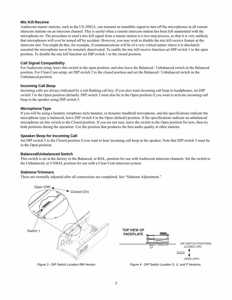
Mic Kill ReceiveAudiocom master stations, such as the US-2002A, can transmit an inaudible signal to turn off the microphones in all remoteintercom stations on an intercom channel. This is useful when a remote intercom station has been left unattended with themicrophone on. The procedure to send a mic kill signal from a master station is a two-step process, so that it is very unlikelythat microphones will ever be turned off by accident. However, you may wish to disable the mic kill receive feature at theintercom unit. You might do this, for example, if communications will be of a very critical nature where it is absolutelyessential the microphone never be remotely deactivated. To enable the mic kill receive function set DIP switch 1 to the openposition. To disable the mic kill function set DIP switch 1 to the closed position.
Call Signal CompatibilityFor Audiocom setup, leave this switch in the open position, and also leave the Balanced / Unbalanced switch in the Balancedposition. For Clear-Com setup, set DIP switch 2 to the closed position and set the Balanced / Unbalanced switch in theUnbalanced position.
Incoming Call BeepIncoming calls are always indicated by a red-flashing call key. If you also want incoming call beep in headphones, set DIPswitch 3 to the Open position (default). DIP switch 3 must also be in the Open position if you want to activate incoming callbeep to the speaker using DIP switch 5.
Microphone TypeIf you will be using a headset, telephone-style handset, or dynamic handheld microphone, and the specifications indicate themicrophone type is balanced, leave DIP switch 4 in the Open (default) position. If the specifications indicate an unbalancedmicrophone set this switch to the Closed position. If you are not sure, leave the switch in the Open position for now, then tryboth positions during the operation. Use the position that produces the best audio quality at other stations.
Speaker Beep for Incoming CallSet DIP switch 5 to the Closed position if you want to hear incoming call beep in the speaker. Note that DIP switch 3 must bein the Open position.
Balanced/Unbalanced SwitchThis switch is set at the factory to the Balanced, or BAL, position for use with Audiocom intercom channels. Set the switch tothe Unbalanced, or UNBAL position for use with a Clear-Com intercom system.
Sidetone TrimmersThese are normally adjusted after all connections are completed. See “Sidetone Adjustment.”
Figure 3 - DIP Switch Location RM Version. Figure 4 - DIP Switch Location S, U, and P Versions.

8
Headset Connector NotesIf you are using a monaural, dynamic-mic headset, or a monaural, telephone-style, dynamic-mic handset, or a handhelddynamic microphone, plug it into the Headset connector. You can also use this connector with monaural headphones forlistening when you are using either the built in panel microphone, or the optional gooseneck microphone for talk back.
Panel Mic Connector NotesAs an alternative to a headset or telephone-style handset, you can use either the built-in panel microphone or an optionalgooseneck microphone. To connect a Telex MCP-90 gooseneck microphone, insert the 1/4” TRS connector into the panelmicrophone connector and screw the microphone in. When a gooseneck microphone is inserted in the panel microphoneconnector, the built-in panel microphone is automatically bypassed. Use either of these microphones for talk back, then usethe internal speaker for listening, or connect a pair of headphones to the headset connector for private listening.
Intercom Channel Connectionsthe method of connection depends on the type of box. The “S” box, “P” box, and RM versions connect to the intercom systemusing prefabricated cables in a phantom-powered configuration. The “U” box version is designed for permanent installation,and it can be either phantom powered or locally powered.
Description of Phantom Powered Connection
Figure 5 - An example of a phantom powered system. In this system a PS-2001L power supply is set to isolate mode. In this mode eachchannel is a separate party line and current per channel is limited to 1 amp. Note that both single and two channel intercom stations may beconnected by using “Y” cables (or JB2 Junction boxes). Prefabricated cables may be used, or cables may be constructed using the diagramsin FIgure 11.
In this method, operating power and intercom audio for the entire intercom system ware carried over the same wires. Theadvantage of this method is simplicity of connection. The system power supply (PS-2001L, SPS-2001A) etc.) automaticallyprovides what is know as a terminating impedance for the intercom system. Without this terminating impedance, the soundquality will be distorted, and the levels will shift every time additional stations are connected. The disadvantage of thephantom power method is that some operating power is lost over very long intercom cables, and performance at distant

9
intercom stations may be reduced. Generally, if intercom stations are within a few hundred feet from the system power supply,phantom power will be sufficient. Also note that increasing the number of stations will reduce the overall operating distance.Phantom power is generally the only method that will be used to connect the “S” box, “P” box, and RM versions. Figure 5illustrates a phantom powered intercom system.
Note that the distance over which power can be delivered is less than the distance over which audio can be delivered. Audiocan be delivered for several miles to locally powered stations as described below.
Description of Locally Powered ConnectionUsing this method, an intercom station is connected to the intercom line just like any phantom-powered intercom station,except that a local power supply is also connected. This local power supply is located with the intercom station and providespower for that station only. Since power loss on the intercom lines is no longer an issue, the operating range is now limitedonly to the audio transmission range, which is several miles. Another advantage to this method is that more stations can beconnected to the intercom channels. When local power is supplied to an intercom station, the station detects this and automati-cally disconnects from the system’s phantom power supply.
Figure 6 illustrates an intercom system with both phantom powered and locally powered “U” boxes. As long as a systempower supply (PS-2001L, SPS-2001, etc.) is located somewhere in the intercom system, the proper terminating impedancewill still be suppled for all stations. However, if all stations are locally powered, and there is not system power supply, aspecial line termination must be installed.
Figure 6 - A two-channel Audiocom intercom system using a PS2001L power supply. the PS2001L is set to isolate mode. In isolate mode,each intercom channel is a separate party line, and total current for each channel is limited to 1 amp. Note that both SS1002 and SS2002stations may be connected depending on each location’s need to communicate with one or two channels. SS1002 stations may beconnected to either channel one or two. Also note that locally powered stations may be connected. This is recommended when stations areinstalled at remote locations. Since the PS2001L provides termination for the intercom channels, no user-installed termination is required.
10
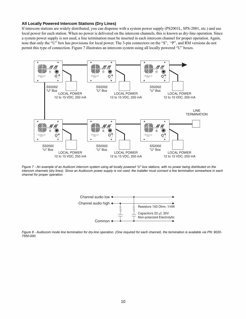
All Locally Powered Intercom Stations (Dry Lines)If intercom stations are widely distributed, you can dispense with a system power supply (PS2001L, SPS-2001, etc.) and uselocal power for each station. When no power is delivered on the intercom channels, this is known as dry-line operation. Sincea system power supply is not used, a line termination must be inserted in each intercom channel for proper operation. Again,note that only the “U” box has provisions for local power. The 3-pin connectors on the “S”, “P”, and RM versions do notpermit this type of connection. Figure 7 illustrates an intercom system using all locally powered “U” boxes.
Figure 7 - An example of an Audicom intercom system using all locally powered “U” box stations, with no power being distributed on theintercom channels (dry lines). Since an Audiocom power supply is not used, the installer must connect a line termination somewhere in eachchannel for proper operation.
Figure 8 - Audiocom mode line termination for dry-line operation. (One required for each channel). the termination is available via PN: 9020-7550-000.

11
Figure 9 - Audiocom mode connections for an SS1002 Intercom Station in a “U” box. Note: for Clear-Com connection, use the UnbalancedMode Intercom Channel pin-out information listed in the Specifications section.
12
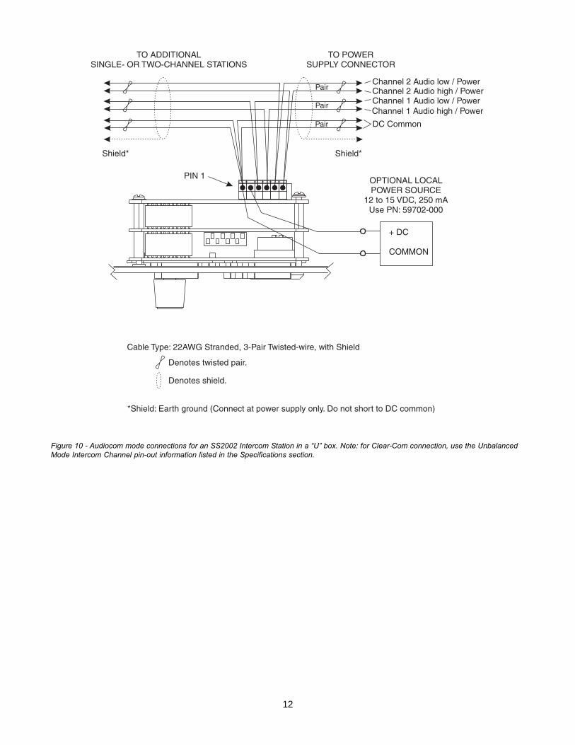
Figure 10 - Audiocom mode connections for an SS2002 Intercom Station in a “U” box. Note: for Clear-Com connection, use the UnbalancedMode Intercom Channel pin-out information listed in the Specifications section.
13
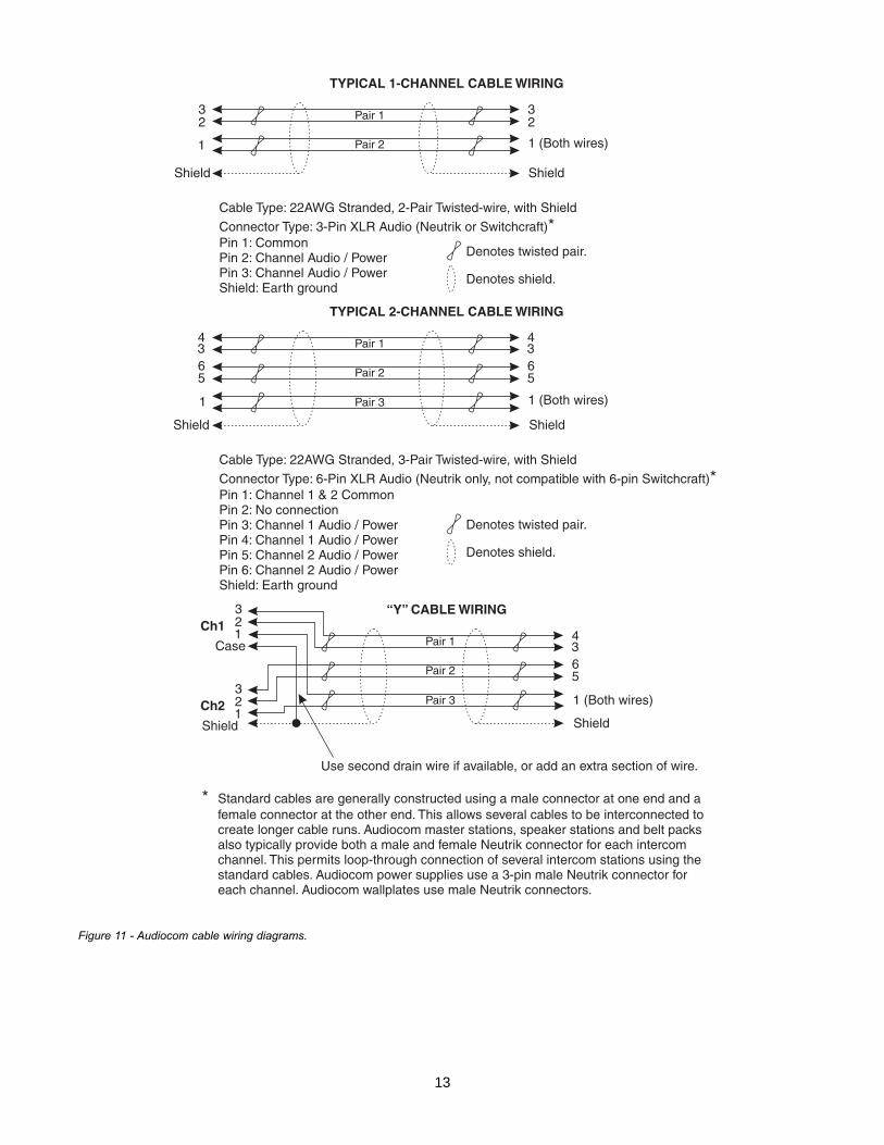
Figure 11 - Audiocom cable wiring diagrams.

14
Power-UpMake sure any local power supplies are plugged in, then turn on the power switches of any phantom power supplies (PS-2001L, SPS-2001, etc.)
Sidetone AdjustmentThe SS-1002, SS-2002, and SS-2002RM use full-duplex audio (the same as conventional telephone lines) in which the talkand listen audio are sent and received on the same wires. Thus, when you talk, you also here your own voice back as with atelephone. If you are using the built-in speaker for listening and a either a panel microphone or handheld microphone fortalkback, you could experience unwanted feedback since the microphone may pick up your returned voice audio from thespeaker and re-amplify it. This could also happen if you are using a headset or headphones with open-ear style earmuffs. Onthe other hand, if you are using earmuffs that completely enclose the ears, the microphone is not likely to pick up the returnedaudio. A certain amount of your own voice level is desirable to overcome the muffled sensation when talking. The sidetoneadjustment is different for these different operating conditions:
If you are suing the speaker with a panel microphone, or if you are using an open-ear style headset or headphones,adjust sidetone as follows:
1. SS-2002 & SS-2002RM only: activate channel 1 as described in the operating instructions.
2. Activate talk and listen as described in the operating instructions
3. Slowly increase the volume to maximum while talking into the microphone.
4. Using a small flat-bladed screwdriver, adjust the channel 1 sidetone trimmer to minimize your voice level in the head-phones.
5. SS-2002 & SS-2002RM only: activate channel 2 and repeat the above steps to adjust the channel 2 sidetone.
6. Install the intercom station mounting screws after completing the adjustments. The station is now ready for use.
If you are using headphones that completely enclose the ears, adjust sidetone as follows:
1. SS-2002 & SS-2002RM only: activate channel 1 as described in the operating instructions.
2. Activate talk and listen as described in the operating instructions.
3. Set the volume control to the normal listening level for intercom audio
4. While talking into the microphone, use a small flat-bladed screwdriver to adjust the channel 1 sidetone trimmer so that youcan hear your own voice in the headphones at an acceptable level.
5. SS-2002 & SS-2002RM only: activate channel 2 and repeat the above steps to adjust the channel 2 sidetone.
15
OperationChannel Select (SS-2002 & SS-2002RM Only)Tap the Ch Select key to select channel 1 or 2. The key is green when channel 1 is selected and red when channel two isselected.
Headset/Headphone/Speaker/Microphone Selection• To use a headset or telephone style handset, set the Speaker and Panel Mic keys to off.• To use headphones with the built-in panel microphone, set the Speaker key to off, set the Panel Mic Key to on, and make
sure that a gooseneck microphone is not inserted in the panel microphone connector.• To use headphones with a gooseneck microphone, set the Speaker key to off, set the Panel Mic Key to on, and make sure
that a gooseneck microphone is inserted in the panel microphone connector.• To use the speaker with a handheld dynamic microphone, set the speaker key to on and set the Panel Mic Key to off.• To use the speaker with the built-in panel microphone, set the Speaker and Panel Mic keys to on, and make sure that a
gooseneck microphone is not inserted in the panel microphone connector.• To use the speaker with a gooseneck microphone, set the Speaker and Panel Mic keys to on, and make sure that a goose-
neck microphone is inserted in the panel microphone connector.
Receiving CallsWhen there is an incoming call signal, the Call key will flash red. There will also be a beep tone in the headphones or speakerif the beep feature is activated.
NOTE: The incoming call indication is provided only for the currently selected intercom channel in the case of SS-2002 &SS-2002RM models.
Turn on the Talk and Listen keys and begin your conversation. Turn the keys off when finished.
NOTE: You can turn the talk and listen keys on in either momentary or latched mode. For momentary operation, press andhold the key. For latched operation, tap the key to turn it on. Then tap it again to turn it off when finished.
Calling an Intercom Channel1. SS-2002 & SS-2002RM only: select the desired intercom channel.
2. Press and hold the Call key. An inaudible call signal will be sent, and the Listen key will automatically turn on.
3. When you hear a response, release the call key and activate the talk key.
4. Turn off your Talk and Listen keys to end the conversation.

16
SpecificationsGeneralPower Requirements:
Phantom Power: +24 VDC nominal, 175 mALocal Power: +12 to +15 VDC, 250 mA
Dimensions: See dimension drawings.Environmental Requirements:
Storage: -20°C to 80°C; 0% to 95% RH, non-condensingOperating: -15°C to 60°C; 0% to 95% RH, non-condensing
Dynamic-mic Headset/HandsetMicrophone: 50 to 200 ohms, dynamic (balanced or unbalanced)Headphones: 150 to 600 ohms, monauralConnector Type: XLR-4M
Pin 1 - Microphone LowPin 2 - Microhpne HighPin 3 - Headphone HighPin 4 - Headphone Low
Panel MicrophoneBuilt-in Microphone:
2.2k ohms, electret (-44 dB nominal), OmnidirectionalGooseneck Microphone:
Connector Type: ¼” Threaded TRS5k ohms, electret (-47 dB nominal)Tip - Microphone High (+12 VDC bias)Ring - CommonSleeve - CommonCompatible with MCP-90 Series Microphones
Intercom Channels, Balanced mode (SW1 set to BAL position)Output Level: 1Vrms nominalInput Impedance: 300 ohmsBridging Impedance: greater than 10k ohmsSidetone: -40 dB, 35 dB adjustable rangeCall Signaling:
Send: 20 kHz ±100 Hz, 0.5 Vrms ±10%Receive: 20 kHz ±800 Hz, 100 mVrms
Mic-Kill Detect Frequency: 24 kHz ±800 Hz, 100mVrmsNoise Contribution: less than -70 dBCommon Mode Rejection Ratio: greater than 50 dBConnector Type: Six-position push type terminal blockPin 1 - Audio and DC CommonPin 2 - Local power (+12 to +15 VDC) If neededPin 3 - Intercom channel 1 audio low and +24 VDC powerPin 4 - Intercom channel 1 audio high and +24 VDC powerPin 5 - Intercom channel 2 audio low and +24 VDC powerPin 6 - Intercom channel 2 audio high and +24VDC power
Intercom Channels, Unbalanced mode (SW1 set to UNBAL position)Output Level: 0.70 Vrms ±10%Input Impedance: 200 ohmsBridging Impedance: greater than 10k ohmsSidetone: -40 dB, 35 dB adjustable range

17
Call Signaling:Pin 1 - CommonPin 2 - Local power (+12 to +15 VDC) If neededPin 3 - Power +30 VDCPin 4 - Intercom channel 1 audio and DC call signalingPin 5 - Power +30 VDCPin 6 - Intercom channel 2 audio and DC call signaling
Speaker Output Power4W max @ 8 ohms
Dimensions
18
TRADEMARKSAudiocom® is a registered trademark of Telex Communications. Names of other products mentioned herein are used for identificationpurposes only and may be trademarks and/or registered trademarks of their respective companies.
WARRANTY INFORMATIONProducts are warranted by Telex Communications, Inc. to be free from defects in materials and workmanship for a period of one year from thedate of sale.
The sole obligation of Telex during the warranty period is to provide, without charge, parts and labor necessary to remedy covered defectsappearing in products returned prepaid to Telex. This warranty does not cover any defect, malfunction or failure caused beyond the control ofTelex, including unreasonable or negligent operation, abuse, accident, failure to follow instructions in the manual, defective or improperassociated equipment, attempts at modification and repair not authorized by Telex, and shipping damage. Products with their serial numbersremoved or effaced are not covered by this warranty.
To obtain warranty service, follow the procedures entitled “Procedure for Returns” and “ Shipping to Manufacturer for Repair or Adjustment”.
This warranty is the sole and exclusive express warranty given with respect to Audiocom products. It is the responsibility of the user todetermine before purchase that this product is suitable for the user’s intended purpose.
ANY AND ALL IMPLIED WARRANTIES, INCLUDING THE IMPLIED WARRANTY OF MERCHANTABILITY ARE LIMITED TO THE DURA-TION OF THIS EXPRESS LIMITED WARRANTY.
NEITHER TELEX NOR THE DEALER WHO SELLS TELEX PRODUCTS IS LIABLE FOR INCIDENTAL OR CONSEQUENTIAL DAMAGESOF ANY KIND.
CUSTOMER SUPPORTTechnical questions should be directed to:
Customer Service DepartmentTelex12000 Portland Avenue SouthBurnsville, MN 55337 U.S.ATelephone: (952) 884-4051Fax: (952) 884-0043
RETURN SHIPPING INSTRUCTIONSProcedure for ReturnsIf a return is necessary, contact the dealer where this unit was purchased.
If a return through the dealer is not possible, obtain a RETURN AUTHORIZATION from:
Customer Service DepartmentTelex Communications, Inc.Telephone: 1-800-392-3497 or (952) 884-4051Fax: 1-800-323-0498 or (952) 884-0043
DO NOT RETURN ANY EQUIPMENT DIRECTLY TO THE FACTORY WITHOUT FIRST OBTAINING A RETURN AUTHORIZATION.
Be prepared to provide the company name, address, phone number, a person to contact regarding the return, purchase order number, thetype and quantity of equipment, a description of the problem and the serial number(s).
Shipping to Manufacturer for Repair or AdjustmentAll shipments of products should be made via United Parcel Service or the best available shipper prepaid. The equipment should be shippedin the original packing carton; if that is not available, use any suitable container that is rigid and of adequate size. If a substitute container isused, the equipment should be wrapped in paper and surrounded with at least four inches of excelsior or similar shock-absorbing material. Allreturns must include the return authorization number. Units sent for repair or adjustment DO NOT need a return authorization number
Factory Service departmentTelex Communications, Inc.West 1st StreetBlue Earth, MN 56013 U.S.A.
Upon completion of any repair the equipment will be returned via United Parcel Service or specified shipper collect.