srw 312 eng - thk technical support · prevents foreign matter and water adhering to the top ... zz...
TRANSCRIPT

SRW
RollerRoller
NEW
CATALOG No.312-1EThis catalog uses recycled paper.
Wide Type Roller Guide with Caged TechnologyUltra-High Rigidity, Heavy LoadLow FrictionLong Service Life, Long-Term Maintenance-Free Operation
W

1
Roller
Roller cage
Retainer plate
Pipe
End seal
Endplate
LM block
LM rail
Roller Guide with Caged Technology Model SRW
Based on Roller Guide with Caged Technology model SRG, this model has a wider railand two rows of LM rail mounting holes to achieve high mounting strength andmounting stability. Use of the roller cage allows low friction and smooth motion.Thus, model SRW is an ultra-high rigidity Roller Guide that achieves long-termmaintenance-free operation.
SRW
45°
45°
45°
45°
Roller cage (component that holds rollers)
Fig. 1 Structure of Model SRW
Magnified view of the circulation path Cross section
Rollercage

2
Applied moment M (kN·m)0 0.2 0.4 0.6 0.8 1
0
0.0015
0.001
0.0005Gra
dien
t ta
n θ
SRG45LR
SRW70LR
Features of Model SRW● Super-ultra-high RigiditySince it has a wide rail and can be secured on the table using the two rows of mounting bolts, the mounting strength issignificantly increased. In addition, since the crosswise raceway distance is large (wide), model SRW is structurallystrong against a moment load (MC moment) in the rolling direction.Model SRW uses rollers that show little elastic deformation as its rolling elements, and the overall length of each roller is1.5 times greater than the diameter, thus to increase the rigidity.
L
● Smoothness Achieved through Skewing PreventionThe roller cage allows rollers to form an evenly spaced line while circulating, thus preventing the rollers from skewing as theblock enters a loaded area. As a result, fluctuation of the rolling resistance is minimized, and stable, smooth motion is achieved.
● Long-term Maintenance-free OperationUse of the roller cage eliminates friction between rollers and enables thelubricant to be retained in grease pockets formed between adjacent rollers. Asthe balls circulate, the grease pocket serves to provide the required amount oflubricant to the contact curvature of the spacer and the roller, thus to achievelong-term maintenance-free operation.
Grease pocket
Fig. 2 Result of Comparison between Models SRW and SRG in Moment Rigidity in the Rolling Direction (MC Moment)
Width dimension: approx. 1.5 times greater
Secured using two rowsof mounting bolts
Fig. 3 Comparison between Models SRW and SRG in Cross Section
Fig. 4
Moment in the rolling direction(MC moment)

3
OptionsIf foreign matter or dust enters model SRW, it may lead to abnormal wear of the product, damage of the raceway or rollersor damage of the circulation structure, which may shorten the service life.Therefore, where entry of foreign matter or dust is predictable, it is necessary to take an effective dust-preventionmeasure that meets the service environment.THK offers a wide range of options in order to respond to extensive service environments.When desiring to use one of the options, indicate that the option is required when placing an order for the product.
● Seals
Dust Prevention Accessories
■ End sealAttached to both ends of the LM block, the end sealprevents foreign matter and water adhering to the topand side faces of the LM rail from entering the LM block.This accessory is available as standard as a means toprevent the lubricant inside the LM block from leaking.
■ Side sealThe side seal blocks foreign matter and water fromentering the LM block from its lower side face. It is alsoeffective in preventing the lubricant from leaking from thebottom of the LM block.
End seal
Hexagon socket tapping screw
Side seal
Side seal
■ Double sealsThe double-seal assembly is an option designed toachieve increased sealability. Even if the first end sealfails to trap part of foreign matter, the second seal trapsit, thus to prevent it from entering the LM block.
■ Inner sealIf a small quantity of foreign matter or dust scrapingthrough the end seal enters the LM block, the inner sealprevents the foreign matter from reaching the rollerraceway and retains the lubricant on the roller raceway.
Double seals
Hexagon socket bolt
Inner seal
Inner seal
Fig. 5 Fig. 6
Fig. 7 Fig. 8

L (standard LM block length)
Overall LM block length with a dust prevention accessory attached
Fig. 11
4
● Scrapers
● Symbols of Dust Prevention Accessories
● Seal Resistance
■ Metal Scraper (Non-contact)The metal scraper is used to remove relatively largeforeign matter or solid foreign matter, such as cuttingchips, spatter and sand dust, which adheres to the LMrail.
If a dust prevention accessory is required, indicate thecorresponding symbol shown in table 1.The overall LM block length increases according to thetype of the dust prevention accessory. Refer to table 2below.
■ LaCS (Laminated Contact Scraper)Unlike the metal scraper, LaCS removes foreign matterthrough surface contact with the LM rail. As a result, itdemonstrates a high dust-prevention effect againstminute foreign matter, which was difficult to remove withthe metal scraper.
Metal scraper
Hexagon socket bolt
Fig. 9
LaCS
Hexagon socket bolt
Resistance
32
37
43
Model No.
SRW 70
SRW 85
SRW 100
Unit: N
Fig. 10
180.8
225.8
291.8
UU
190
235
303
SS
190
235
303
DD
199.2
244.2
314.2
ZZ
197.2
242.2
311.4
KK
206.4
251.4
322.6
SSHH
217
262
335.4
DDHH
226.2
271.2
346.6
ZZHH
220.2
265.2
338.6
KKHH
229.4
274.4
349.8
Model No.
SRW 70
SRW 85
SRW 100
Unit: mmNo option attached
Table 2 Overall LM Block Length of Model SRW with a DustPrevention Accessory Attached
Table 3 Seal Resistance
For the maximum seal resistance per LM block of model SRW attached with seals (symbol SS), see the correspondingvalue provided in table 3.
Note: The values in the table each indicate themaximum the seal resistance value per LM blockcontaining grease.
With end seal (both ends)
With end seal + side seal + inner seal (standard)
With double seals + side seal + inner seal
With end seal + side seal + inner seal + metal scraper
With double seals + side seal + inner seal + metal scraper
With end seal + side seal + inner seal + LaCS
With double seals + side seal + inner seal + LaCS
With end seal + side seal + inner seal + metal scraper + LaCS
With double seals + side seal + inner seal + metal scraper + LaCS
UU
SS
DD
ZZ
KK
SSHH
DDHH
ZZHH
KKHH
Dust prevention accessorySymbol
Table 1 Symbols of Dust Prevention Accessories forModel SRW
5
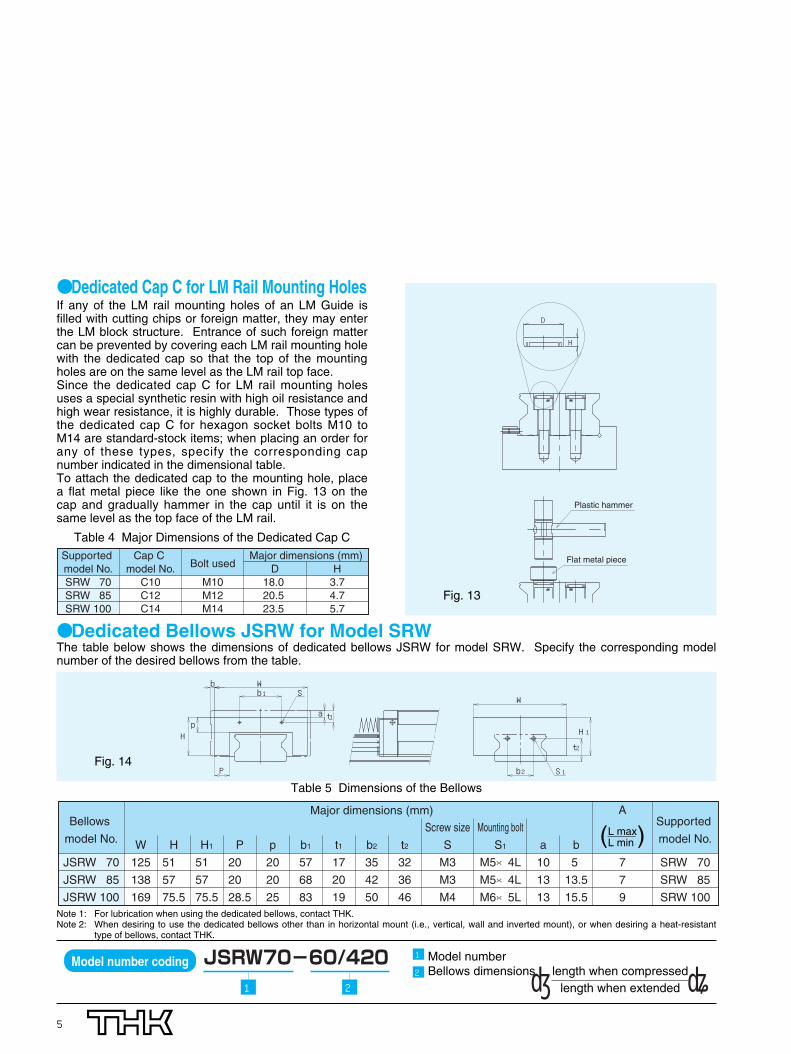
● Dedicated Cap C for LM Rail Mounting HolesIf any of the LM rail mounting holes of an LM Guide isfilled with cutting chips or foreign matter, they may enterthe LM block structure. Entrance of such foreign mattercan be prevented by covering each LM rail mounting holewith the dedicated cap so that the top of the mountingholes are on the same level as the LM rail top face. Since the dedicated cap C for LM rail mounting holesuses a special synthetic resin with high oil resistance andhigh wear resistance, it is highly durable. Those types ofthe dedicated cap C for hexagon socket bolts M10 toM14 are standard-stock items; when placing an order forany of these types, specify the corresponding capnumber indicated in the dimensional table.To attach the dedicated cap to the mounting hole, placea flat metal piece like the one shown in Fig. 13 on thecap and gradually hammer in the cap until it is on thesame level as the top face of the LM rail.
Flat metal piece
Plastic hammer
D
H
Fig. 13
D18.0 20.5 23.5
Major dimensions (mm)Cap C model No.
C10C12C14
Bolt used
M10M12M14
H3.74.75.7
Supported model No.SRW 70SRW 85SRW 100
● Dedicated Bellows JSRW for Model SRWThe table below shows the dimensions of dedicated bellows JSRW for model SRW. Specify the corresponding modelnumber of the desired bellows from the table.
Wb
b
P
H
a t
S
p
W
b
t
H
S1
1
1
1
2
2Fig. 14
Bellows
model No.
JSRW 70
JSRW 85
JSRW 100
Major dimensions (mm)
W
125
138
169
H
51
57
75.5
H1
51
57
75.5
P
20
20
28.5
p
20
20
25
b1
57
68
83
t1
17
20
19
b2
35
42
50
t2
32
36
46
Screw size
S
M3
M3
M4
Mounting bolt
S1
M5×4L
M5×4L
M6×5L
a
10
13
13
b
5
13.5
15.5
A
7
7
9
Supported
model No.
SRW 70
SRW 85
SRW 100
L maxL min( )
Note 1: For lubrication when using the dedicated bellows, contact THK.Note 2: When desiring to use the dedicated bellows other than in horizontal mount (i.e., vertical, wall and inverted mount), or when desiring a heat-resistant
type of bellows, contact THK.
Table 5 Dimensions of the Bellows
Table 4 Major Dimensions of the Dedicated Cap C
Model number coding
1 2
Model numberBellows dimensions length when compressed
length when extended〔 〕1
2

6
QZ™ LubricatorQZ Lubricator is a lubrication system that feeds the right amount of lubricant to the right place by contacting a highlydense fiber net to the raceway.
■ Allows a Significant Increase of the Maintenance IntervalWith ordinary grease lubrication, a minimal amount of oil is lost as the system travels. QZ Lubricator supplements lost oilto drastically extend the maintenance interval.
■ An Environmentally Friendly Lubrication SystemAn environmentally friendly lubrication system that does not contaminate the surrounding area since it feeds the rightamount of lubricant to the ball raceway through a highly dense fiber net.
■ Allows Oil Setting According to the Intended UseQZ Lubricator allows the setting of oil according to the service conditions. Contact THK for details.
With end seal + QZ
With end seal + side seal + inner seal + QZ
With double seals + side seal + inner seal + QZ
With end seal + side seal + inner seal + metal scraper + QZ
With double seals + side seal + inner seal +metal scraper + + QZ
With end seal + side seal + inner seal + LaCS + QZ
With double seals + side seal + inner seal + LaCS + QZ
With end seal + side seal + inner seal + metal scraper + LaCS + QZ
With double seals + side seal + inner seal + metal scraper + LaCS + QZ
QZUU
QZSS
QZDD
QZZZ
QZKK
QZSSHH
QZDDHH
QZZZHH
QZKKHH
Dust prevention accessory with QZ LubricatorSymbol
QZ
Hexagon socket bolt
Highly dense fiber net
Roller
Roller cageFlow of lubricant
Oil control plate
Highly oil-impregnated fiber net
Case
Fig. 15
QZUU
220
275
343
QZSS
220
275
343
QZDD
229.2
284.2
354.2
QZZZ
229.2
284.2
354.2
QZKK
238.4
293.4
365.4
QZSSHH
247
302
375.4
QZDDHH
256.2
311.2
386.6
QZZZHH
250.2
305.2
378.6
QZKKHH
259.4
314.4
389.8
Model No.
SRW 70
SRW 85
SRW 100
Unit: mm
Table 6 Symbols of Dust Prevention Accessories including QZ Lubricator for Model SRW
Table 7 Overall LM Block Length of Model SRW with QZ Lubricator Attached

7
Grease PortModel SRW allows lubrication from both the side and top faces of the LM block. The grease port of standard types is notdrilled through in order to prevent foreign matter from entering the LM block.When using the grease port, contact THK.
ø D2 depth 1 Grease port on the top face
ø D0 Side nipple
e1
e0
V
f0
Fig. 16
e0
7
9
9
Pilot hole for side nipple Grease port on the top face
f0
17
17.7
22.4
D0
5.2
5.2
5.2
Applicable
nipple
M6F
M6F
M6F
D2 (O ring)
13(P10)
13(P10)
13(P10)
V
0.4
0.4
0.4
e1
33.7
42.75
55
Model No.
SRW 70
SRW 85
SRW 100
Unit: mmTable 8 Dimensions of the Grease Port
8
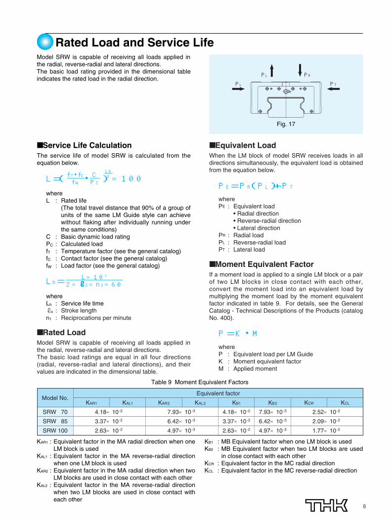
Rated Load and Service LifeModel SRW is capable of receiving all loads applied inthe radial, reverse-radial and lateral directions.The basic load rating provided in the dimensional tableindicates the rated load in the radial direction.
■ Service Life CalculationThe service life of model SRW is calculated from theequation below.
whereL : Rated life
(The total travel distance that 90% of a group ofunits of the same LM Guide style can achievewithout flaking after individually running underthe same conditions)
C : Basic dynamic load ratingPC : Calculated loadfT : Temperature factor (see the general catalog)fC : Contact factor (see the general catalog)fW : Load factor (see the general catalog)
whereLh : Service life timers : Stroke lengthn1 : Reciprocations per minute
■ Rated LoadModel SRW is capable of receiving all loads applied inthe radial, reverse-radial and lateral directions.The basic load ratings are equal in all four directions(radial, reverse-radial and lateral directions), and theirvalues are indicated in the dimensional table.
■ Equivalent LoadWhen the LM block of model SRW receives loads in alldirections simultaneously, the equivalent load is obtainedfrom the equation below.
wherePE : Equivalent load
• Radial direction• Reverse-radial direction• Lateral direction
PR : Radial loadPL : Reverse-radial loadPT : Lateral load
■ Moment Equivalent FactorIf a moment load is applied to a single LM block or a pairof two LM blocks in close contact with each other,convert the moment load into an equivalent load bymultiplying the moment load by the moment equivalentfactor indicated in table 9. For details, see the GeneralCatalog - Technical Descriptions of the Products (catalogNo. 400).
whereP : Equivalent load per LM GuideK : Moment equivalent factorM : Applied moment
PRPLPTPL
4.18×10⁻²
3.37×10⁻²
2.63×10⁻²
KAR1 KAR2 KAL2 KB1
4.18×10⁻²
3.37×10⁻²
2.63×10⁻²
KB2
7.93×10⁻³
6.42×10⁻³
4.97×10⁻³
Equivalent factor
KAL1
2.52×10⁻²
2.09×10⁻²
1.77×10⁻²
KCR KCL
7.93×10⁻³
6.42×10⁻³
4.97×10⁻³
Model No.
SRW 70
SRW 85
SRW 100
KAR1 : Equivalent factor in the MA radial direction when oneLM block is used
KAL1 : Equivalent factor in the MA reverse-radial directionwhen one LM block is used
KAR2 : Equivalent factor in the MA radial direction when twoLM blocks are used in close contact with each other
KAL2 : Equivalent factor in the MA reverse-radial directionwhen two LM blocks are used in close contact witheach other
KB1 : MB Equivalent factor when one LM block is usedKB2 : MB Equivalent factor when two LM blocks are used
in close contact with each otherKCR : Equivalent factor in the MC radial directionKCL : Equivalent factor in the MC reverse-radial direction
Fig. 17
Table 9 Moment Equivalent Factors
L=( ・ )×100fT・fCfW
CPC
103
PE=PR(PL)+PT
P=K・M
Lh= L×1032×rS×n1×60

9
Precautions on Use■Height of the Mounting Surface and the Shape of the CornerFor the shoulder heights of the mounting surfaces for the LM rail and the LM block, we recommend selecting thecorresponding values from table 10. The corner of the mounting surface must be recessed, or must be machined so thatthe corner radius is equal to or below the corner radius (of the LM block/LM rail) indicated in table 10, in order not tointerfere with the chamfer of the LM block or the LM rail.
■Removing/mounting JigWhen assembling the guide, do not remove the LM block from the LM rail whenever possible. If it is inevitable to remove ormounting the LM block due to the assembly procedure, be sure to use the removing/mounting jig.Mounting the LM block without using the removing/mounting jig may lead rolling elements to fall off from the LM block dueto inclusion of foreign matter, damage to an internal part or a slight gradient. Also, be sure not to mount and use the LMblock with some of the rolling elements missing, since doing so may result in early fracture of the LM system.When using the removing/mounting jig, be careful not to tilt it and be sure to match the end face of the jig with that of the LM rail.If any of the rolling elements has fallen off from the LM block, stop using the system and contact THK.The removing/mounting jig is not provided as standard. When desiring to use it, contact THK.
LM rail section LM Guide section
H2
r2
r2
r1
r1H1
E
Model No.
SRW 70
SRW 85
SRW 100
Corner radius
(LM rail section)
r1 (max)
1.5
1.5
1.5
Corner radius
(LM block section)
r2 (max)
1.5
1.5
2
Shoulder height
(LM rail section)
H1
6
8
9
Shoulder height
(LM block section)
H2
8
10
10
E
8
10
11.5
Unit: mm
Removing/mounting jig (Material: ABS resin)
Removing/mounting jig
LM rail
LM block
Fig. 18
Table 10 Shoulder Height of the Mounting Surface and Corner Radius
Fig. 19

10
Accuracy of the Mounting SurfaceModel SRW is highly rigid since it uses rollers as its rolling elements, and the roller cage prevents the rollers fromskewing. However, the mounting surface needs to be finished with high accuracy.
The following tables show error allowances of the mounting surface that will not affect the rolling resistance or service lifein normal operation.
Normal
0.013
0.016
0.020
C1
0.009
0.011
0.014
C0
0.007
0.008
0.011
Model No.
SRW 70
SRW 85
SRW 100
Radial clearance
Unit: mm
Par
alle
lism
er
ror
P
a
X2
X1
Table 11 Error in Parallelism (P) between Two Rails
Normal
0.00020a
C1
0.00014a
C0
0.000072a
Radial clearance
Unit: mm
Error allowance (X) of the mounting surface
Table 12 Error in Level (X) between the Rails
0.000036・bAccuracy of the mounting surface
Unit: mmTable 13 Error in Level (Y) in the Axial Direction
Fig. 20
Fig. 21
b
Y
Fig. 22
Example ofcalculation
Rail spanwhen a = 500 mm
Accuracy of themounting surface
X=0.0002×500=0.1
X=X1+X2 X1: Level difference on the rail mountingsurface
X2: Level difference on the block mountingsurface

11
Accuracy StandardsAs shown in table 14, the accuracy of model SRW isspecified in terms of running parallelism, dimensionaltolerance for height and width, and height and widthdifference between a pair when 2 or more LM blocks areused on one rail or when 2 or more rails are mounted onthe same plane.
■Running parallelismSee the general catalog for details.
■Difference in Height MSee the general catalog for details.
■Difference in Width W2 See the general catalog for details.
Unit: mm
Mode No.
SRW70SRW85
SRW100
Accuracy standard
ItemDimensional tolerance for height MDifference in height MDimensional tolerance for width W2
Difference in width W2
Running parallelism of surface C against surface ARunning parallelism of surface D against surface BDimensional tolerance for height MDifference in height MDimensional tolerance for width W2
Difference in width W2
Running parallelism of surface C against surface ARunning parallelism of surface D against surface B
Precision grade
P0
-0.05 0.0070
-0.05 0.01
0 -0.07 0.01 0
-0.07 0.015
Super-precision gradeSP
0 -0.03 0.0050
-0.03 0.007ΔD
(as shown in Fig. 23 and 24)ΔD
(as shown in Fig. 23 and 24)0
-0.05 0.0070
-0.05 0.01 ΔC
(as shown in Fig. 23 and 24)ΔD
(as shown in Fig. 23 and 24)
Ultra-super precision grade
UP0
-0.02 0.0030
-0.02 0.005
0 -0.03 0.0050
-0.03 0.007
A
D
B
C
M
W2
Radial Clearance
Table 14 Accuracy Standards
Fig. 23
0
10
20
30
10000 2000 3000
△C
△D
(μm)
LM rail length (mm)
P
SPUP
Fig. 24 LM Rail Length and Running Parallelism
Fig. 25
Normal
No symbol
-2 ~ -1
-2 ~ -1
-3 ~ -1
Light preload
C1
-3 ~ -2
-4 ~ -2
-5 ~ -3
Medium preload
C0
-5 ~ -3
-6 ~ -4
-8 ~ -5
Model No.
SRW 70
SRW 85
SRW 100
Indication symbol
Table 15 Radial Clearance of Model SRW
Table 15 shows radial clearance of model SRW.
Note: Add no symbol for normal clearance; add C0 or C1
to the model number for clearance C0 orclearance C1, respectively.(See the model number coding.)
Radial clearance
12
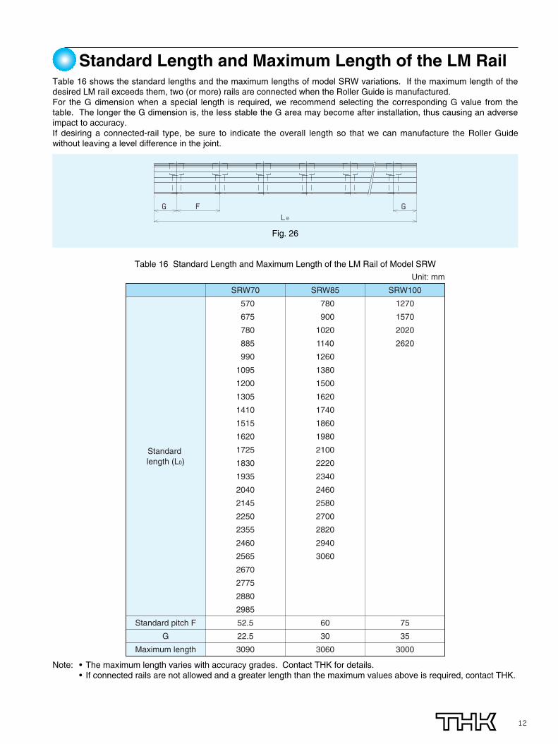
Standard Length and Maximum Length of the LM RailTable 16 shows the standard lengths and the maximum lengths of model SRW variations. If the maximum length of thedesired LM rail exceeds them, two (or more) rails are connected when the Roller Guide is manufactured. For the G dimension when a special length is required, we recommend selecting the corresponding G value from thetable. The longer the G dimension is, the less stable the G area may become after installation, thus causing an adverseimpact to accuracy.If desiring a connected-rail type, be sure to indicate the overall length so that we can manufacture the Roller Guidewithout leaving a level difference in the joint.
G FL0
G
SRW70
570
675
780
885
990
1095
1200
1305
1410
1515
1620
1725
1830
1935
2040
2145
2250
2355
2460
2565
2670
2775
2880
2985
52.5
22.5
3090
Standard pitch F
G
Maximum length
SRW85
780
900
1020
1140
1260
1380
1500
1620
1740
1860
1980
2100
2220
2340
2460
2580
2700
2820
2940
3060
60
30
3060
SRW100
1270
1570
2020
2620
75
35
3000
Unit: mm
Standard length (L0)
Note: • The maximum length varies with accuracy grades. Contact THK for details.• If connected rails are not allowed and a greater length than the maximum values above is required, contact THK.
Fig. 26
Table 16 Standard Length and Maximum Length of the LM Rail of Model SRW

13
Model number
No. of LM blocks to be used on thesame axis.
QZ Lubricator
Symbol for dust prevention accessory(note 1) (see page 4)
Radial clearance symbol (see page 11)
LM rail length (mm)
Accuracy symbol (see page 11)
No. of shafts used on the same plane(note 2)
Dimensional Table for Model SRW ... LR
Model No.
SRW70LR
SRW85LR
SRW100LR
Height
M
70
80
100
Width
W
135
165
200
Outer dimensions LM block length
Length
L
190
235
303
B
115
140
172
B1
34
40
50
C
80
95
110
S×r
M10×20
M12×19
M14×20
L1
142
179.2
229.8
K
62
70
88.5
T
20
28
20
N
20
22
27
E
16
16
16
e0
7
9
9
D0
5.2
5.2
5.2
Greasenipple
B-PT1/8
B-PT1/8
B-PT1/8
f0
17
17.7
22.4
Model number coding
1 2 3 4 5 6 7 9
1
2
3
7
9
W1W2
T
W
(K)M
MC
4
5
6
14
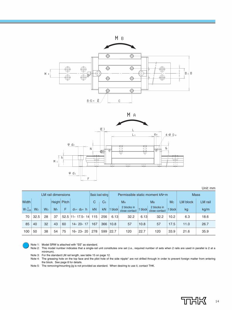
Note 1: Model SRW is attached with “SS” as standard.Note 2: This model number indicates that a single-rail unit constitutes one set (i.e., required number of sets when 2 rails are used in parallel is 2 at a
minimum).Note 3: For the standard LM rail length, see table 15 on page 12.Note 4: The greasing hole on the top face and the pilot hole of the side nipple* are not drilled through in order to prevent foreign matter from entering
the block. See page 8 for details.Note 5: The removing/mounting jig is not provided as standard. When desiring to use it, contact THK.
LM rail dimensions Basic load rating Permissible static moment kN・m Mass
Unit: mm
MA MBWidth
W1
70
85
100
Height
M1
37
43
54
Pitch
F
52.5
60
75
d1×d2×h
11×17.5×14
14×20×17
16×23×20
C
kN
115
167
278
C0
kN
256
366
599
1 block
6.13
10.8
22.7
1 block
6.13
10.8
22.7
MC
1 block
10.2
17.5
33.9
LM block
kg
6.3
11.0
21.6
LM rail
kg/m
18.6
26.7
35.9
32.2
57
120
32.2
57
120
W2
32.5
40
50
W3
28
32
38
0-0.05
2 blocks in close contact
2 blocks in close contact
BB1W3
C8-S×r
MB
L1L(E)
N f0
F
M1h
4-φD0
φd1
φd2
e0
MA

● “LM Guide,” “Ball Cage,” “ ,” and “QZ” are registered trademarks of THK CO., LTD.● The photo may differ slightly in appearance from the actual product.● The appearance and specifications of the product are subject to change without notice. Contact THK before placing an order.● Although great care has been taken in the production of this catalog, THK will not take any responsibility for damage resulting from typographical errors or omissions.● For the export of our products or technologies and for the sale for exports, THK in principle complies with the foreign exchange law and the Foreign Exchange
and Foreign Trade Control Law as well as other relevant laws.For export of THK products as single items, contact THK in advance. All rights reserved
Roller Guide with Caged Technology Model SRW
Precautions on Use● Handling
Dropping or hitting the LM block may damage it. Use much care when handing it.● Use of the Pilot Holes of the Top and Side Nipples
If desiring to use the pilot holes of the top and side nipples (holes are not drilled through to prevent entry offoreign matter) of the LM block, contact THK.The nipples are attached at THK. The pilot holes of the top and side nipples are designed exclusively formounting nipples. Do not use them for other purposes. Doing so may damage them.
● ReinstallationWhen removing the LM block from the LM rail and reinstalling the block, be sure to use the removing/mountingjig and carefully remove/mount the LM block.The removing/mounting jig is not provided as standard. When desiring to use it, contact THK.
● CoolantWhen planning to use the LM system in an environment where the coolant penetrates the LM block, it maycause trouble to product functions depending on the type of the coolant. Contact THK for details.
● Service Temperature RangeThe LM block uses a special resin. Do not use it at temperature of 80ºC or higher.
● Service EnvironmentIn locations exposed to constant vibrations or in special environments such as clean rooms, vacuum andlow/high temperature, normal lubricants may not be used. Contact THK for details.
● LubricationThe roller cage technology allows a longer greasing interval than the full-roller type. However, the greasinginterval varies with service environments such as high load and high speed. Contact THK for details.
● Installation of the LM BlockTo obtain sufficient rigidity of the LM block, be sure to secure it using eight bolts.
● Accuracy of the Mounting SurfaceThe Roller Guide is a highly rigid guide. Note, however, that poor accuracy of the mounting surface maydegrade the accuracy of the guide, shorten its service life and cause damage to it.
20040905 Printed in Japan
HEAD OFFICE 3-11-6, NISHI-GOTANDA, SHINAGAWA-KU, TOKYO 141-8503 JAPAN ASIA PACIFIC SALES DEPARTMENT PHONE:(03)5434-0351 FAX:(03)5434-0353
CHINABEI JINGPHONE:(10)6590-3557 FAX:(10)6590-3557
THK SHANGHAI CO., LTD.PHONE:(21)6334-5131 FAX:(21)6334-5137
THK SHOUZAN CO.,LTD.PHONE:2376-1091 FAX:2376-0749
TAIWANTAIPEIPHONE:(02)2888-3818 FAX:(02)2888-3819
TAICHUNGPHONE:(04)2359-1505 FAX:(04)2359-1506
SOUTHERNPHONE:(06)289-7668 FAX:(06)289-7669
KOREA (SEOUL)PHONE:(02)3463-0351 FAX:(02)3017-0351
MALAYSIA (KUALA LUMPUR)PHONE:(03)9287-1137 FAX:(03)9287-8071
INDIA (BANGALORE)PHONE:(080)330-1524 FAX:(080)330-1524
NORTH AMERICACHICAGOPHONE:(847)310-1111 FAX:(847)310-1182
NEW JERSEYPHONE:(201)529-1950 FAX:(201)529-1962
ATLANTAPHONE:(770)840-7990 FAX:(770)840-7897
LOS ANGELESPHONE:(714)891-6752 FAX:(714)894-9315
SAN FRANCISCOPHONE:(925)455-8948 FAX:(925)455-8965
BOSTONPHONE:(781)575-1151 FAX:(781)575-9295
DETROITPHONE:(248)858-9330 FAX:(248)858-9455
TORONTOPHONE:(905)712-2922 FAX:(905)712-2925
BRASIL (SÃO PAULO)PHONE:(011)3767-0100 FAX:(011)3767-0101
EUROPEDÜSSELDORF
PHONE:0049-(0)2102-7425-0 FAX:0049-(0)2102-7425-299STUTTGART
PHONE:0049-(0)7150-9199-0 FAX:0049-(0)7150-9199-888MÜNCHEN
PHONE:0049-(0)89-370616-0 FAX:0049-(0)89-370616-26U.K.
PHONE:0044-(0)1908-303050 FAX:0044-(0)1908-303070MILANO
PHONE:0039-039-2842079 FAX:0039-039-2842527BOLOGNA
PHONE:0039-051-6412211 FAX:0039-051-6412230SWEDEN
PHONE:0046-(0)8-4457630 FAX:0046-(0)8-4457639AUSTRIA
PHONE:0043-(0)7229-51400 FAX:0043-(0)7229-51400-79SPAIN
PHONE:0034-93-652-5740 FAX:0034-93-652-5746THK FRANCE S. A. S.
PHONE:0033-(0)4-37491400 FAX:0033-(0)4-37491401SOUTH AFRICA
PHONE:0027-(0)44-2720020 FAX:0027-(0)44-2720020