sri vidya college of engineering and technology department ... · pdf filetechnology...
TRANSCRIPT

G.SANKAREESWARI CS2028
Sri Vidya College of Engineering andTechnologyDepartment of Computer Science &Engineering
Class II CSE / II ITSubject Code CS6401Subject Operating SystemsPrepared By G.SankareeswariLesson Plan for Computer System OverviewTime: 50 MinutesLesson. No 1/10
1. Topics to be Covered: Computer System Overview
2. Skills Addressed: Listening
3. Objectives of this Lesson Plan:
1. To enable students to understand the basic concepts of operating systems.
4. Outcome (s): What are Operating Systems?
What are mainframe systems?
What are desktop systems?
What are Multiprocessor systems?
Difference between system view, user view and system goals.
5. link sheet6. Evocation
Evocation: (5 Minutes)

G.SANKAREESWARI CS2028
What is an Operating System?
OS is a program that acts as an intermediary between a user of acomputer and the computer hardware
Operating system goals:o Execute user programs and make solving user problems
easiero Make the computer system convenient to use
Use the computer hardware in an efficientmanner
Operating System
We don’t know what an OS is exactly until we have learned this course, but we may havesome clues about the answer. Let’s think about it. Whenever we want to use computers, wehave to boot them up first. Whatever happens in this period, we know it is the OS that is incharge of it. After the computer is available for use, we then interact with the computerthrough a graphical interface or text-only console. We may run programs, install or uninstallapplications in the OS as we need. Thus the following picture may be suitable for describinga computer system:
Thus, we may conclude that an operating system exploits and manages all kinds of computerhardware to provide a set of services directly or indirectly to the users.
Services may be functions the human users can use directly, e.g. file creation, usermanagement, etc., and also those that may be used indirectly, which embody as applicationprogramming interface, all kinds of libraries and functions they provide.

G.SANKAREESWARI CS2028
Computer system overview
To build an OS, as we can see from the figure, I need to know more details about thehardware. In a computer system, there are all kinds of hardware, CPUs, mainboards,monitors, network adapters, sound cards, mice, keyboards, printers, hard disks, etc.Mainboard is not something that provides a specific function, instead it is a collection of allkinds of slots and modules. To make all these things work together, mainboard providessome kind of physical connections among them, i.e. what we call system bus. Thus based onour analysis, all these components may be divided into several groups: CPU, memory, I/Omodules and system bus.
Instead of I/O devices, we use I/O modules because it is those I/O modules thatcommunicate directly with CPU or memory.
As for memory, we may also say it is a kind of storage I/O module; however it has a specialposition in the system since we never heard of drivers for memory to work but I have knownplenty of drivers for a variety of I/O modules. Those drivers are actually programs, whichhave to be loaded into memory to run. Obviously, memory cannot depend on a driver,instead the system includes physical circuits for accessing memory.

G.SANKAREESWARI CS2028
Sri Vidya College of Engineering andTechnologyDepartment of Computer Science &Engineering
Class II CSE / II ITSubject Code CS6401Subject Operating SystemsPrepared By G.SankareeswariLesson Plan for Basic Elements, Instruction ExecutionTime: 50 MinutesLesson. No 2/10
1. Topics to be Covered: Basic Elements, Instruction Execution
2. Skills Addressed: Listening
3. Objectives of this Lesson Plan:
2. To enable students to understand the basic concepts of operating systems basicelements.
4. Outcome (s): To know what are all the Basic Elements in computer
Registers
Data Registers
Adress register
5. link sheet6. Evocation
Evocation: (5 Minutes)

G.SANKAREESWARI CS2028
Basic elements
To depict these components and their connections, we present the following top-level view:
According to the figure, data may be transferred between CPU and memory, or CPU and I/Omodules, or even memory and I/O modules.
As we know, a memory consists of a set of locations, defined by a sequentially numberedaddresses. Each location may be a byte of 8 bits, or a word of 16 bits. It contains abinarynumber that can be interpreted as either an instruction or pure data.
To access data in memory, CPU makes use of two internal registers: MAR (memory addressregister) and MBR (memory buffer register). MAR specifies the address in memory for thenext read/write; MBR otherwise contains the data to be written into memory, or data to beread from memory. Similarly, I/OAR specifies a particular I/O module, and I/OBR is usedfor the exchange of data between an I/O module and the processor.
An I/O module transfers data from external devices to CPU and memory, and vice versa. Itcontains buffers for temporarily holding data until they can be sent on.

G.SANKAREESWARI CS2028
Computer Startup
Bootstrap programis loaded at power-up or reboot
Typically stored in ROM or EPROM, generally known as firmware
Initializes all aspects of system
Loads operating system kernel and starts execution
Computer System Organization
Computer-system operation
One or more CPUs, device controllers connect through common bus providingaccess to shared memory
Computer-System Operation
I/O devices and the CPU can execute concurrently
Each device controller is in charge of a particular device type
Each device controller has a local buffer
CPU moves data from/to main memory to/from local buffers
I/O is from the device to local buffer of controller

G.SANKAREESWARI CS2028
Device controller informs CPU that it has finished its operation by causing aninterrupt
RegistersComputers compute. The component that performs computation is CPU, or more concretelyit is the ALU (arithmetic logical unit) in CPU that do the computation. To compute, we needfirst prepare input; however ALU cannot access memory directly, Instead, a set of registersare provided as a cache that is faster but smaller than main memory. (They are smallerbetweenthey are much more expensive than regular memory.)
Except for the registers directly involved in computation, CPU also has some registers in thepurpose of control and recording status.
The textbook categorizes registers into two types: user-visible registers, and control andstatus registers. Since this separation is not common, so here we just explain registers one byone without labelling them as one of which kind.
Data registers
MOV AX, 1234H
MOV [4321H], AL
Address registersSegmented addressing registers
We may naturally assume that, to access some location of memory, we simply use anaddress register to contain the address of that location, but the actual practice is kind ofmuch more complex. One popular addressing method is segmented addressing. Withthis method, memory is divided into segments, and each segment are variable-lengthblocks of words. To refer to a location in such a memory system, we need to give twopieces ofinformation. One is which segment, and the other is which item in that segment we arevisiting. That is the address consists of two parts, segment address, and the offsetwithin the segment. Accordingly there are two kinds of registers: segment addressregisters and offset address registers. For example, CPU x8086, shifts the content ofCS to the left by 4 bits, and then adds up the result and the content of IP. Finally thesum is used as the effective address.
CS : IP
DS : DI
DS : SI

G.SANKAREESWARI CS2028
It should be made clear that segment is just a logical concept, not an physicallyexistingentity in memory. We may simply write to CS to change the segment it pointsto.
Stack pointers
Due to the popularity of stack in programs execution, computer systems provideregisters to access memory segment in the way of accessing stacks. For example, inx8086, we have
SS : SPwhere SS gives the stack segment, and SP always points to the top of the stack. Thusthe following two sets of instructions have the same effect:
PUSH AX SUB SP, 2
MOV [SS:SP], AX
Control registers
All the registers we discuss above are related to data access, however we know, memoryalso contains instructions for CPU to execute. In this purpose, CPU provides
Program counter (PC)
contains the address of an instruction to be fetched from memory
Instruction register (IR)
contains the instruction most recently fetched.
The execution of an instruction is actually to interpret the operation code in the instructionand generate signals for ALU or other components in CPU. For example, when xy=00, ALUdoes A+B => C, and when xy=01, ALU does A-B => C, etc.
| | | | | | | | | | | || | | | | | | | | | | |.---------- . . ---------- .\ A \ / B /
\ \ / /\ V / -----x\ C /------ y.----------------- .| | | | | | | |

G.SANKAREESWARI CS2028
| | | | | | | |Status registersBesides the above types of registers, CPU also includes registers, that contain status infor-mation. They are known as PSW (program status word). PSW typically contains conditioncodes plus other status information.
Condition codes are bits set by the processor hardware as the result of operations. Forexample, an arithmetic operation may produce a positive, negative, zero, or overflow result.In addition to the result itself being stored in a register or memory, a condition code is alsoset following the execution of the instruction. The code may subsequently be tested as partof conditional branch operation. Let’s say
CMP AX, BXJGE exit...
exit:...
Generally, these condition codes cannot be altered by explicit reference because they are in-tended for feedback regarding the execution of an instruction, and are updated automaticallywhenever a related instruction is executed. For example, we aren’t supposed to use thefollow-ing instruction to clear the lowest bit of PSW register.
OR PSW, FEHThe registers we give here are all very common ones. A CPU may actually provide muchmore registers. There are a number of factors that have to be taken into account. One isoperating- system support. Certain types of control information are of specific utility to theoperating system. If the processor designer has a functional understanding of the operatingsystem to be used, then register organization can be designed to provide hardware supportfor particular features such as memory protection and switching between user program.These features may originally be implemented in software.Another key factor is theallocation of control information between registers and memory. Although registers aremuch faster, but due to the price reason, a computer system doesn’t have many registers, soat least part of control information has to be put into memory. Thus here comes a problem ofbalance. You need to consider what control information is more frequently used and inwhich order.
Instruction execution
The previous section mainly addresses the static characteristics of a processor, this sectionotherwise talks about its dynamic side - instruction execution.
A program to be executed a CPU consists of a set of instructions stored in memory.Roughly, the execution of an instruction may be looked on as a process of two steps. At thefirst step, the instruction is read (fetched) from memory into IR, whose address is specifiedby PC register.
Then at the second step, CPU executes the instruction, i.e. interpreting the instruction and

G.SANKAREESWARI CS2028
performing the action specified. The first step is called fetch cycle and the second executecycle. The whole process of the two steps is called instruction cycle. Thus programexecution is actually repeating instruction cycles until either the computer is turned off, oran instruction that asks CPU to halt is encountered. The following figure depicts thisprocess:
In a typical processer, the register PC contains the address of the instruction to be fetchednext. Whenever an instruction is obtained, the content of PC will increment automatically sothat it will fetch the next instruction in sequence.
The fetched instruction is loaded into IR. The inst ruction contains bits that specify theaction the processor is to take. In general, these actions fall into four categories:
• data exchange between CPU and memory
• data exchange between CPU and I/O modules
There are two popular methods to address I/O modules. One is allocating part ofmemory address space for I/O modules, thus to read/write from/to an I/O module,same instructions as used to access memory will do without any change. Of course,you have to specify addresses in the instructions that are corresponding to I/Omodules. The other method is using a separate set of instructions for I/O module. Forexample, in CPU x8086, the following instructions are used:
MOV DX, 61H
OUT DX, AL…
MOV DX, 60H
IN AL, DX
• data processing
The processer may perform some arithmetic or logic operation on data.
• controlSome instructions may affect the sequence of execution. For example:

G.SANKAREESWARI CS2028
JMP 0700H...CMP AL, 08HJNE different...
An example is given in the textbook to show how a partial program is executed step by stepto add two numbers up.

G.SANKAREESWARI CS2028
Sri Vidya College of Engineering andTechnologyDepartment of Computer Science &Engineering
Class II CSE / II ITSubject Code CS6401Subject Operating SystemsPrepared By G.SankareeswariLesson Plan for Interrupts, Memory HierarchyTime: 50 MinutesLesson. No 3/10
1. Topics to be Covered: Interrupts, Memory Hierarchy
2. Skills Addressed: Listening
3. Objectives of this Lesson Plan:
3. To enable students to understand the basic concepts of operating systems.
4. Outcome (s): What is Interrupts?
Memory Hierarchy
Cache
Direct
5. link sheet6. Evocation
Evocation: (5 Minutes)

G.SANKAREESWARI CS2028
INTERRUPTS
Interrupt transfers control to the interrupt service routine generally, through the interruptvector,which contains the addresses of all the service routines
Interrupt architecture must save the address of the interrupted instruction
A trapor exceptionis a software-generated interrupt caused either by an error or a user request
An operating system is interrupt driven
INTERRUPT HANDLING
The OS preserves the state of the CPU by storing registers and the program counter
Determines which type of interrupt has occurred:
polling
The interrupt controller polls (send a signal out to) each device to determine which onemade the request
Vectored interrupt system
Separate segments of code determine what action should be taken for each type ofinterruptINTERRUPT TIMELINE
I/O STRUCTURE Synchronous (blocking) I/O
Waiting for I/O to complete
Easy to program, not always efficient

G.SANKAREESWARI CS2028
Waitinstruction idles the CPU until the next interrupt
At most one I/O request is outstanding at a time
Asynchronous (nonblocking) I/O
After I/O starts, control returns to user program without waiting for I/O completion
Harder to program, more efficient
System call –request to the OS to allow user to wait for I/O completion (polling periodically tocheck busy/done)
Device-status table contains entry for each I/O device indicating its type, address, and state
STORAGE DEFINITIONS AND NOTATION REVIEW
The basic unit of computer storage is the bit. A bit can contain one of two values, 0 and 1. Allother storage in a computer is based on collections of bits. Given enough bits, it is amazing howmany things a computer can represent: numbers, letters, images, movies, sounds, documents, andprograms, to name a few. A byte is 8 bits, and on most computers it is the smallest convenientchunk of storage. For example, most computers don’t have an instruction to move a bit but dohave one to move a byte. A less common term is word, which is a given computer architecture’snative unit of data. A word is made up of one or more bytes. For example, a computer that has64-bit registers and 64-bit memory addressing typically has 64-bit (8-byte) words. A computerexecutes many operations in its native word size rather than a byte at a time.
Computer storage, along with most computer throughput, is generally measured and manipulatedin bytes and collections of bytes.
A kilobyte, or KB, is 1,024 bytesa megabyte, or MB, is 1,0242bytesa gigabyte, or GB, is 1,0243bytesa terabyte, or TB, is 1,0244 bytesa petabyte, or PB, is 1,0245bytes
Computer manufacturers often round off these numbers and say that a megabyte is 1 millionbytes and a gigabyte is 1 billion bytes. Networking measurements are an exception to thisgeneral rule; they are given in bits (because networks move data a bit at a time).
STORAGE STRUCTURE
Main memory –only large storage media that the CPU can access directly
Random access

G.SANKAREESWARI CS2028
Typically volatile
Secondary storage –extension of main memory that provides large nonvolatilestorage capacity
Hard disks –rigid metal or glass platters covered with magnetic recording material
Disk surface is logically divided into tracks, which are subdivided into sectors
The disk controller determines the logical interaction between the device and the computer
Solid-state disks –faster than hard disks, nonvolatile
Various technologies
Becoming more popular
STORAGE HIERARCHY
Storage systems organized in hierarchy
Speed
Cost (per byte of storage)
Volatility
Device Driver for each device controller to manage I/O
Provides uniform interface between controller and kernel
G.SANKAREESWARI CS2028
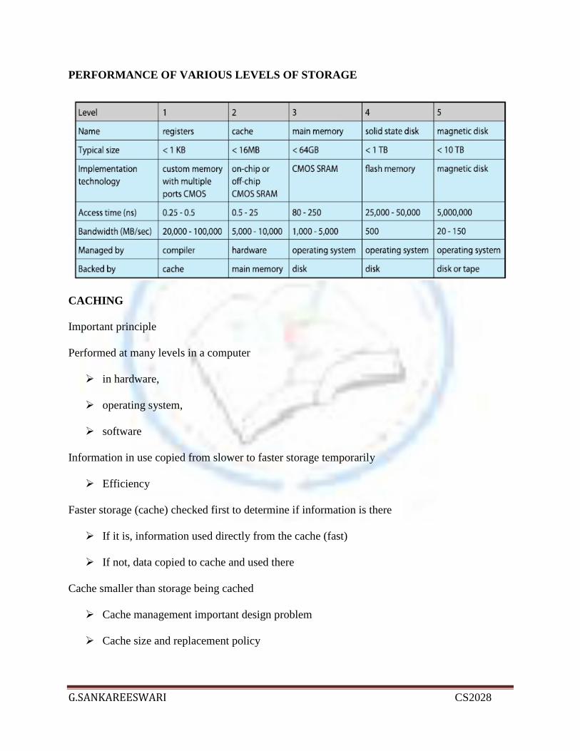
PERFORMANCE OF VARIOUS LEVELS OF STORAGE
CACHING
Important principle
Performed at many levels in a computer
in hardware,
operating system,
software
Information in use copied from slower to faster storage temporarily
Efficiency
Faster storage (cache) checked first to determine if information is there
If it is, information used directly from the cache (fast)
If not, data copied to cache and used there
Cache smaller than storage being cached
Cache management important design problem
Cache size and replacement policy

G.SANKAREESWARI CS2028
Direct Memory Access Structure
Typically used for I/O devices that generate data in blocks, or generate data fast
Device controller transfers blocksof data from buffer storage directly to main memory withoutCPU intervention
Only one interrupt is generated per block, rather than the one interrupt per byte
How a Modern Computer Works
A von Neumann architecture

G.SANKAREESWARI CS2028
Sri Vidya College of Engineering andTechnologyDepartment of Computer Science &Engineering
Class II CSE / II ITSubject Code CS6401Subject Operating SystemsPrepared By G.SankareeswariLesson Plan for Multiprocessor And Multi Core OrganizationTime: 50 MinutesLesson. No 4/10
1. Topics to be Covered: Interrupts, Memory Hierarchy
2. Skills Addressed: Listening
3. Objectives of this Lesson Plan:
4. To enable students to understand the basic concepts of operating systems.
4. Outcome (s): What is multi processor system ?
What is multi core system?
5. link sheet6. Evocation
Evocation: (5 Minutes)

G.SANKAREESWARI CS2028
Computer-System Architecture
Most systems use a single general-purpose processor
Most systems have special-purpose processors as well
Multiprocessorssystems growing in use and importance
Also known as parallel systems, tightly-coupled systems
Advantages include:
1.Increased throughput
2.Economy of scale
3.Increased reliability –graceful degradation or fault tolerance
Two types:
1.Asymmetric Multiprocessing –each processor is assigned a specific task
2.Symmetric Multiprocessing –each processor performs all tasksSymmetric Multiprocessing Architecture
A Dual-Core DesignMulticore
Several cores on a single chip

G.SANKAREESWARI CS2028
On chip communication is faster than between-chip
Less power used
Clustered Systems
Like multiprocessor systems, but multiple systems working together
Provides a high-availabilityservice which survives failures
Asymmetric clusteringhas one machine in hot-standby mode
Symmetric clusteringhas multiple nodes running applications, monitoring each other
Some clusters are for high-performance computing (HPC)
Applications must be written to useparallelization

G.SANKAREESWARI CS2028

G.SANKAREESWARI CS2028
Sri Vidya College of Engineering andTechnology
Department of Computer Science &Engineering
Class II CSE / II ITSubject Code CS2254Subject Operating SystemsPrepared By G.SankareeswariLesson Plan for Operating system overviewTime: 50 MinutesLesson. No 5/10
1. Topics to be Covered: Introduction to Operating Systems
2. Skills Addressed: Listening
3. Objectives of this Lesson Plan:
5. To enable students to understand the basic concepts of operating systems.
4. Outcome (s): What are Operating Systems?
What are mainframe systems?
What are desktop systems?
What are Multiprocessor systems?
Difference between system view, user view and system goals.
5 Link Sheet: -

G.SANKAREESWARI CS2028
6 Evocation: (5 Minutes)
7 Lecture Notes: (attached)
8 Textbook :1. Abraham Silberschatz, Peter Baer Galvin and Greg Gagne, “Operating System Concepts”, 9 th
Edition, John Wiley and Sons Inc., 2012.
9 Application Cellular Phones Video Games Computers Networks

G.SANKAREESWARI CS2028
Operating System
A program that acts as an intermediary between a user of a computer and the computerhardware.
Operating system goals:oExecute user programs and make solving user problems easier.oMake the computer system convenient to use.
Use the computer hardware in an efficient manner. Computer system can be divided into four components:
oThe hardware – CPU, Memory, I/O DevicesoThe Operating systemoThe Application programs – word processor, spread sheets, compilers & web
browsersoThe Users
Operating System Definitions: OS is a resource allocator
o Manages all resourceso Decides between conflicting requests for efficient and fair resource use
OS is a control programo Controls execution of programs to prevent errors and improper use of the
computero Concerned with the operation & control of I/O deviceso Kernel – one program running at all times on the computer.
Mainframe systems Reduces setup time by batching similar jobs Automatic job sequencing – automatically transfers control from one job to another Resident monitor
o Initial control in monitoro Control transfer to jobo When job completes control transfer to monitor
Multi-programmed system Several jobs are kept in main memory at the same time and the CPU is multiplexed
among them OS features needed for multiprogramming:
o I/O routine supplied by the systemo Memory management: The system must allocate the memory to several jobso CPU Scheduling: The system must choose among seversl jobs to runo Allocation of devices
Time Sharing Systems (Interactive computer systems) CPU is multiplexed among several jobs that are kept in memory and on disk A job is swapped in & out of memory to disk On-line communication b/w the user & the system is provided Allows many users to share the computer simultaneously A program loaded in memory and executing is referred as process

G.SANKAREESWARI CS2028
On-line system must be available for user to access data
Client-Server System
Dumb terminals supplanted by smart PCs Many systems now servers, responding to requests generated by clients
oCompute-server provides an interface to client to request services (i.e. database)oFile-server provides interface for clients to store and retrieve files
Peer-to-Peer System
Another model of distributed system P2P does not distinguish clients and servers
Instead all nodes are considered peers May each act as client, server or both Node must join P2P network
o Registers its service with central lookup service on network, oro Broadcast request for service and respond to requests for service
via discovery protocol Examples include Napster and Gnutella
Desktop Systems
Personal computers: Computer systems dedicated to a single I/O devices: keyboard, mouse, display screen, small printers User convenience and responsiveness Can adopt technology developed for layer OS often individuals have hole use of
computer.
Multiprocessor systems (parallel systems/tightly coupled systems)
Systems have more than one processor in close communication, sharing the computerbus, the clock, and sometimes memory & peripheral devices.
Advantages:o Increased throughputo Economicalo Increased reliability
Symmetric multiprocessing (SMP)o Each processor run & identical copy of OSo Many processes can run at once without performance deteriorationo Most modern operating system supports SMP
Asymmetrico Each processor is assigned to a specific tasko Master schedules & allocates work to slave processors

G.SANKAREESWARI CS2028
o More common in extremely large systems
Sri Vidya College of Engineering andTechnologyDepartment of Computer Science &Engineering
Class II CSE / II ITSubject Code CS6401Subject Operating SystemsPrepared By G.SankareeswariLesson Plan for Evouation Of OSTime: 50 MinutesLesson. No 6/10
1. Topics to be Covered: Computer System Overview
2. Skills Addressed: Listening
3. Objectives of this Lesson Plan:
6. To enable students to understand the basic concepts of operating systems.
4. Outcome (s):
5. link sheet6. Evocation
Evocation: (5 Minutes)

G.SANKAREESWARI CS2028
EVOLUTION OF OPERATING SYSTEMS
Serial Processing
Users access the computer in series. From the late 1940's to mid 1950's, the programmerinteracted directly with computer hardware i.e., no operating system. These machines were runwith a console consisting of display lights, toggle switches, some form of input device and aprinter. Programs in machine code are loaded with the input device like card reader. If an erroroccur the program was halted and the error condition was indicated by lights. Programmersexamine the registers and main memory to determine error. If the program is success, then outputwill appear on the printer.
Main problem here is the setup time. That is single program needs to load source program intomemory, saving the compiled (object) program and then loading and linking together.
Simple Batch Systems
To speed up processing, jobs with similar needs are batched together and run as a group. Thus,the programmers will leave their programs with the operator. The operator will sort programsinto batches with similar requirements.
The problems with Batch Systems are:
Lack of interaction between the user and job. CPU is often idle, because the speeds of the mechanical I/O devices are slower than CPU.
For overcoming this problem use the Spooling Technique. Spool is a buffer that holds output fora device, such as printer, that can not accept interleaved data streams. That is when the jobrequests the printer to output a line, that line is copied into a system buffer and is written to thedisk. When the job is completed, the output is printed. Spooling technique can keep both theCPU and the I/O devices working at much higher rates.
Multiprogrammed Batch Systems
Jobs must be run sequentially, on a first-come, first-served basis. However when several jobs areon a direct-access device like disk, job scheduling is possible. The main aspect of job schedulingis multiprogramming. Single user cannot keep the CPU or I/O devices busy at all times. Thusmultiprogramming increases CPU utilization.
In when one job needs to wait, the CPU is switched to another job, and so on. Eventually, thefirst job finishes waiting and gets the CPU back.
The memory layout for multiprogramming system is shown below:

G.SANKAREESWARI CS2028
Time-Sharing Systems
Time-sharing systems are not available in 1960s. Time-sharing or multitasking is a logicalextension of multiprogramming. That is processors time is shared among multiple userssimultaneously is called time-sharing. The main difference between Multiprogrammed BatchSystems and Time-Sharing Systems is in Multiprogrammed batch systems its objective ismaximize processor use, whereas in Time-Sharing Systems its objective is minimize responsetime.
Multiple jobs are executed by the CPU by switching between them, but the switches occur sofrequently. Thus, the user can receives an immediate response. For example, in a transactionprocessing, processor execute each user program in a short burst or quantum of computation.That is if n users are present, each user can get time quantum. When the user submits thecommand, the response time is seconds at most.
Operating system uses CPU scheduling and multiprogramming to provide each user with a smallportion of a time. Computer systems that were designed primarily as batch systems have beenmodified to time-sharing systems.
For example IBM's OS/360.
Time-sharing operating systems are even more complex than multiprogrammed operatingsystems. As in multiprogramming, several jobs must be kept simultaneously in memory.
Personal-Computer Systems (PCs)
A computer system is dedicated to a single user is called personal computer, appeared in the1970s. Micro computers are considerably smaller and less expensive than mainframe computers.The goals of the operating system have changed with time; instead of maximizing CPU andperipheral utilization, the systems developed for maximizing user convenience andresponsiveness.
For e.g., MS-DOS, Microsoft Windows and Apple Macintosh.
Hardware costs for microcomputers are sufficiently low. Decrease the cost of computer hardware(such as processors and other devices) will increase our needs to understand the concepts ofoperating system. Malicious programs destroy data on systems. These programs may be self-replicating and may spread rapidly via worm or virus mechanisms to disrupt entire companies oreven worldwide networks.
MULTICS operating system was developed from 1965 to 1970 at the Massachusetts Institute ofTechnology (MIT) as a computing utility. Many of the ideas in MULTICS were subsequentlyused at Bell Laboratories in the design of UNIX OS.

G.SANKAREESWARI CS2028
Parallel Systems
Most systems to date are single-processor systems; that is they have only one main CPU.Multiprocessor systems have more than one processor.
The advantages of parallel system are as follows:
throughput (Number of jobs to finish in a time period) Save money by sharing peripherals, cabinets and power supplies Increase reliability Fault-tolerant (Failure of one processor will not halt the system).
Symmetric multiprocessing model
Each processor runs an identical job (copy) of the operating system, and these copiescommunicate. Encore's version of UNIX operating system is a symmetric model.E.g., If two processors are connected by a bus. One is primary and the other is the backup. Atfixed check points in the execution of the system, the state information of each job is copiedfrom the primary machine to the backup. If a failure is detected, the backup copy is activated,and is restarted from the most recent checkpoint. But it is expensive.
Asymmetric multiprocessing model
Each processor is assigned a specific task. A master processor controls the system. Sun'soperating system SunOS version 4 is a asymmetric model. Personal computers contain amicroprocessor in the keyboard to convert the key strokes into codes to be sent to the CPU.
Distributed Systems
Distributed systems distribute computation among several processors. In contrast to tightlycoupled systems (i.e., parallel systems), the processors do not share memory or a clock. Instead,each processor has its own local memory.
The processors communicate with one another through various communication lines (such ashigh-speed buses or telephone lines). These are referred as loosely coupled systems or distributedsystems. Processors in a distributed system may vary in size and function. These processors arereferred as sites, nodes, computers and so on.
The advantages of distributed systems are as follows:
Resource Sharing: With resource sharing facility user at one site may be able to use theresources available at another.
Communication Speedup: Speedup the exchange of data with one another via electronicmail.

G.SANKAREESWARI CS2028
Reliability: If one site fails in a distributed system, the remaining sites can potentiallycontinue operating.
Real-time Systems
Real-time systems are used when there are rigid time requirements on the operation of aprocessor or the flow of data and real-time systems can be used as a control device in a dedicatedapplication. Real-time operating system has well-defined, fixed time constraints otherwisesystem will fail.
E.g., Scientific experiments, medical imaging systems, industrial control systems, weaponsystems, robots, and home-applicance controllers.
There are two types of real-time systems:
Hard real-time systems
Hard real-time systems gurantees that critical tasks complete on time. In hard real-timesystems secondary storage is limited or missing with data stored in ROM. In thesesystems virtual memory is almost never found.
Soft real-time systems
Soft real time systems are less restrictive. Critical real-time task gets priority over othertasks and retains the priority until it completes. Soft real-time systems have limited utilitythan hard real-time systems.
E.g., Multimedia, virtual reality, Advanced Scientific Projects like undersea explorationand planetary rovers.

G.SANKAREESWARI CS2028
Sri Vidya College of Engineering andTechnologyDepartment of Computer Science &Engineering
Class II CSE / II ITSubject Code CS6401Subject Operating SystemsPrepared By G.SankareeswariLesson Plan for Computer system Organization and operationTime: 50 MinutesLesson. No 7/10
1. Topics to be Covered:, Computer system Organization
2. Skills Addressed: Listening
3. Objectives of this Lesson Plan:
7. To enable students to understand the basic concepts of operating systems.
4. Outcome (s): What is multi processor system ?
What is multi core system?
5. link sheet6. Evocation
Evocation: (5 Minutes)

G.SANKAREESWARI CS2028
OPERATING-SYSTEM OPERATIONS
Interrupt driven
(hardware and software)Hardware interrupt by one of the devicesSoftware interrupt ( exception or trap):
Software error (e.g., division by zero)
Request for operating system service
Other process problems include infinite loop, processes modifying each other or theoperating system
Dual-mode operation allows OS to protect itself and other system components
User

G.SANKAREESWARI CS2028
mode and kernel
modeMode bit
provided byhardware
Provides ability to distinguish when system is running user code or
kernel code
Some instructions designated as privileged, only executable in kernel
mode
System call changes mode to kernel, return from call resets it to user
USING TIMER FOR PREVENTING CERTAIN EVENTS
Timer to prevent infinite loop / process hogging resources
Timer is set to interrupt the computer after some time period
Keep a counter that is decremented by the physical clock
Operating system set the counter (privileged instruction)
When counter zero generate an interrupt
Set up before scheduling process to
regain control, or terminate program that exceeds allotted timePROCESS MANAGEMENT
A process is a program in execution. It is a unit of work within the system. Program is a passiveentity, process is an active entity.
Process needs resources to accomplish its task
CPU, memory, I/O, files
Initialization data
Typically system has many processes, some user, some operating system running concurrentlyon one or more CPUs.Concurrency by multiplexing the CPUs among the processes / threads
Process management activities

G.SANKAREESWARI CS2028
The operating system is responsible for the following activities in connection with processmanagement:
Creating and deletingboth user and system processes
Suspendingand resumingprocesses
Providing mechanisms for process synchronization
Providing mechanisms for process communication
Providing mechanisms for deadlock handling
Memory Management
To execute a program all (or part) of the instructions must be in memory
All (or part) of the data that is needed by the program must be in memory.
Memory management determines what is in memory and when
Optimizing CPU utilization and computer response to users
Memory management activities
Keeping track of which parts of memory are currently being used and by whom
Deciding which processes (or parts thereof) and data to move into and out of memory
Allocating and deallocating memory space as needed

G.SANKAREESWARI CS2028
Sri Vidya College of Engineering andTechnology
Department of Computer Science &Engineering
Class II CSE / II ITSubject Code CS2254Subject Operating SystemsPrepared By G.SankareeswariLesson Plan for Operating system structures - System calls - System programsTime: 50 MinutesLesson. No 8/10
1. Topics to be Covered: Operating system structures - System calls - System programs
2. Skills Addressed: Listening
3. Objectives of this Lesson Plan:
8. To enable students To explain Operating System Structures
To define System Calls
To define System Programs.
4. Outcome (s): Describe the services an operating system provides to users, processes, and other
systems
Discuss the various ways of structuring an operating system

G.SANKAREESWARI CS2028
Explain system calls and its categories.
What is a system program?
5 Link Sheet: -
6 Evocation: (5 Minutes)

G.SANKAREESWARI CS2028
7 Lecture Notes: (attached)
8 Textbook :1. Abraham Silberschatz, Peter Baer Galvin and Greg Gagne, “Operating System Concepts”, 9 th
Edition, John Wiley and Sons Inc., 2012.
9 Application Preemptive process Non-preemptive process Computers
An operating system provides the environment within which programs are executed. The designof a new operating system is a major task.
System Components
Process Management: A process is a program in execution. It is a unit of work within the system. Program is a
passive entity, process is an active entity. Process needs resources to accomplish its task
CPU, memory, I/O, files Initialization data
Process termination requires reclaim of any reusable resourcesSingle-threaded process has one program counter specifying location of next instructionto execute
Process executes instructions sequentially, one at a time, until completion Multi-threaded process has one program counter per thread Typically system has many processes, some user, some operating system running
concurrently on one or more CPUs Concurrency by multiplexing the CPUs among the processes
Process Management activities:The operating system is responsible for the following activities in connection with
process management: Creating and deleting both user and system processes Suspending and resuming processes Providing mechanisms for process synchronization Providing mechanisms for process communication Providing mechanisms for deadlock handling
Memory Management: All data in memory before and after processing All instructions in memory in order to execute

G.SANKAREESWARI CS2028
Memory management determines what is in memory when Optimizing CPU utilization and computer response to users
Memory management activities Keeping track of which parts of memory are currently being used and by
whom Deciding which processes (or parts thereof) and data to move into and out
of memory Allocating and deallocating memory space as needed
Storage Management: OS provides uniform, logical view of information storage
Abstracts physical properties to logical storage unit - file Each medium is controlled by device (i.e., disk drive, tape drive) Varying properties include access speed, capacity, data-transferrate, access method (sequential or random)
File-System management Files usually organized into directories Access control on most systems to determine who can access what OS activities include Creating and deleting files and directories Primitives to manipulate files and dirs Mapping files onto secondary storage Backup files onto stable (non-volatile) storage media
Mass-Storage Management: Usually disks used to store data that does not fit in main memory or data that must be
kept for a “long” period of time. Proper management is of central importance Entire speed of computer operation hinges on disk subsystem and its algorithms OS activities
Free-space management Storage allocation Disk scheduling
Some storage need not be fast Tertiary storage includes optical storage, magnetic tape Still must be managed Varies between WORM (write-once, read-many-times) and RW (read-write)
I/O System Management: One purpose of OS is to hide peculiarities of hardware devices from the user I/O subsystem responsible for
Memory management of I/O including buffering (storing data temporarily while itis being transferred), caching (storing parts of data in faster storage forperformance), spooling (the overlapping of output of one job with input of otherjobs)

G.SANKAREESWARI CS2028
General device-driver interface Drivers for specific hardware devices
Operating System Services One set of operating-system services provides functions that are helpful to the user:
User interface - Almost all operating systems have a user interface (UI) Varies between Command-Line (CLI), Graphics User Interface (GUI),
Batch Program execution - The system must be able to load a program into memory and
to run that program, end execution, either normally or abnormally(indicating error)
I/O operations - A running program may require I/O, which may involve a file oran I/O device.
File-system manipulation - The file system is of particular interest. Obviously,programs need to read and write files and directories, create and deletethem, search them, list file Information, permission management.
Communications – Processes may exchange information, on the same computeror between computers over a network Communications may be via shared memory or through message passing
(packets moved by the OS) Error detection – OS needs to be constantly aware of possible errors
May occur in the CPU and memory hardware, in I/O devices, in userprogram
For each type of error, OS should take the appropriate action to ensurecorrect and consistent computing
Debugging facilities can greatly enhance the user’s and programmer’sabilities to efficiently use the system
Resource allocation - When multiple users or multiple jobs runningconcurrently, resources must be allocated to each of them
Many types of resources - Some (such as CPU cycles, mainmemory, andfile storage) may have special allocation code, others (such as I/O devices)may have general request and release code.
Accounting - To keep track of which users use how much and what kinds ofcomputer resources
Protection and security - The owners of information stored in a multiuser ornetworked computer system may want to control use of that information,concurrent processes should not interfere with each other Protection involves ensuring that all access to system resources is
controlled Security of the system from outsiders requires user authentication,
extends to defending external I/O devices from invalid access attempts If a system is to be protected and secure, precautions must be instituted
throughout it. A chain is only as strong as its weakest link.
System calls: Programming interface to the services provided by the OS

G.SANKAREESWARI CS2028
Typically written in a high-level language (C or C++) Mostly accessed by programs via a high-level Application Program Interface (API)
rather than direct system call use Three most common APIs are Win32 API for Windows, POSIX API for POSIX-based
systems (including virtually all versions of UNIX, Linux, and Mac OS X), and Java APIfor the Java virtual machine (JVM)
System Call Implementation: Typically, a number associated with each system call
System-call interface maintains a table indexed according to these numbers The system call interface invokes intended system call in OS kernel and returns status of
the system call and any return values The caller need know nothing about how the system call is implemented
Just needs to obey API and understand what OS will do as a result call Most details of OS interface hidden from programmer by API
Managed by run-time support library (set of functions built into librariesincluded with compiler)
System Call Parameter Passing:
Often, more information is required than simply identity of desired system call Exact type and amount of information vary according to OS and call
Three general methods used to pass parameters to the OS Simplest: pass the parameters in registers
In some cases, may be more parameters than registers Parameters stored in a block, or table, in memory, and address of block passed as
a parameter in a register This approach taken by Linux and Solaris
Parameters placed, or pushed, onto the stack by the program and popped off thestack by the operating system
Block and stack methods do not limit the number or length of parameters beingpassed
Types of System Calls:

G.SANKAREESWARI CS2028
Process control File management Device management Information maintenance Communications
System Programs: System programs provide a convenient environment for program development and
execution. The can be divided into: File manipulation Status information File modification Programming language support Program loading and execution Communications Application programs
Most users’ view of the operation system is defined by system programs, not the actualsystem calls
Provide a convenient environment for program development and execution Some of them are simply user interfaces to system calls; others are considerably
more complex File management - Create, delete, copy, rename, print, dump, list, and generally
manipulate files and directories Status information
Some ask the system for info - date, time, amount of available memory, diskspace, number of users
Others provide detailed performance, logging, and debugging information Typically, these programs format and print the output to the terminal or other
output devices Some systems implement a registry - used to store and retrieve configuration
information File modification
Text editors to create and modify files Special commands to search contents of files or perform transformations of the
text Programming-language support - Compilers, assemblers, debuggers and interpreters
sometimes provided Program loading and execution- Absolute loaders, relocatable loaders, linkage editors,
and overlay-loaders, debugging systems for higher-level and machine language Communications - Provide the mechanism for creating virtual connections among
processes, users, and computer systems Allow users to send messages to one another’s screens, browse web pages, send
electronic-mail messages, log in remotely, transfer files from one machine toanother
Operating System Design & Implementation:

G.SANKAREESWARI CS2028
Important principle to separatePolicy: What will be done?Mechanism: How to do it?
Mechanisms determine how to do something, policies decide what will be done The separation of policy from mechanism is a very important principle, it allows
maximum flexibility if policy decisions are to be changed later
Simple Structure: MS-DOS – written to provide the most functionality in the least space
Not divided into modules Although MS-DOS has some structure, its interfaces and levels of functionality
are not well separatedLayered Approach: The operating system is divided into a number of layers (levels), each built on top of
lower layers. The bottom layer (layer 0), is the hardware; the highest (layer N) is the userinterface.
With modularity, layers are selected such that each uses functions (operations) andservices of only lower-level layers
UNIX: UNIX – limited by hardware functionality, the original UNIX operating system had
limited structuring. The UNIX OS consists of two separable parts Systems programs The kernel
1. Consists of everything below the system-call interface and above the physicalhardware2. Provides the file system, CPU scheduling, memory management, and otheroperating-system functions; a large number of functions for one level

G.SANKAREESWARI CS2028
Sri Vidya College of Engineering andTechnologyDepartment of Computer Science &Engineering
Class II CSE / II ITSubject Code CS6401Subject Operating SystemsPrepared By G.SankareeswariLesson Plan for OS Generation And System BootTime: 50 MinutesLesson. No 9/10
1. Topics to be Covered: Computer System Overview
2. Skills Addressed: Listening
3. Objectives of this Lesson Plan:
9. To enable students to understand the basic concepts of operating systems.
4. Outcome (s): What are Operating Systems?
What are mainframe systems?
What are desktop systems?
What are Multiprocessor systems?
Difference between system view, user view and system goals.
5. link sheet6. Evocation
Evocation: (5 Minutes)

G.SANKAREESWARI CS2028
Operating system generation :
Operating systems are designed to run on any of a class of machines; the system must beconfigured for each specific computer siteSYSGEN program obtains information concerning the specific configuration of thehardware systemBooting – starting a computer by loading the kernelBootstrap program – code stored in ROM that is able to locate the kernel, load it intomemory, and start its execution
Booting an Operating System:

G.SANKAREESWARI CS2028
Sri Vidya College of Engineering and
Technology
Department of Computer Science &
Engineering
Class II CSE / II IT
Subject Code CS6401
Subject Operating Systems
Prepared By G.Sankareeswari
Lesson Plan for Process Concept – Process Scheduling
Time: 50 Minutes
Lesson. No 1/9
1.
Topics to be Covered: Process Concept – Process Scheduling
2.
Skills Addressed: Listening
3. Objectives of this Lesson Plan:
1. To enable students
To learn about the Process Concept.
To explain Process Scheduling.
4.
Outcome (s): What is process?
Explain about process scheduling.
Explain types of scheduling.
5 Link Sheet: -
G.SANKAREESWARI CS2028
6 Evocation: (5 Minutes)

G.SANKAREESWARI CS2028
7 Lecture Notes: (attached)
8 Textbook :
1. Abraham Silberschatz, Peter Baer Galvin and Greg Gagne, “Operating System Concepts”, 9 th
Edition, John Wiley and Sons Inc., 2012.
9 Application
Automobile
Mobile
Computers

G.SANKAREESWARI CS2028
Process:
a program in execution
process execution must progress in sequential fashion
Process concept:
An operating system executes a variety of programs:
Batch system – jobs
Time-shared systems – user programs or tasks
Textbook uses the terms job and process almost interchangeably.
A process includes:
program counter (program counter)
stack (temporary date-> method parameter,retur adder of local variable)
data section (global variable)
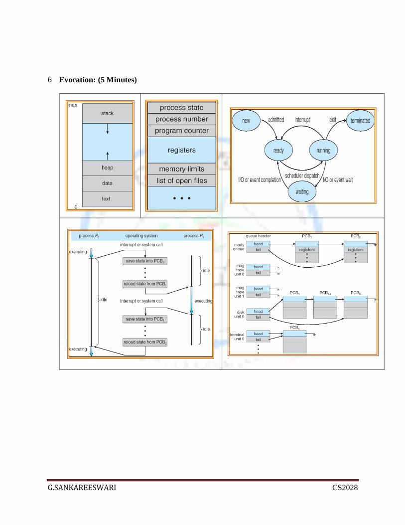
Process state:
As a process executes, it changes state
State -> in part by current activity of the process
new: The process is being created
running: Instructions are being executed
waiting: The process is waiting for some event to occur
ready: The process is waiting to be assigned to a processor
terminated: The process has finished execution
Virtual Machine:
A virtual machine takes the layered approach to its logical conclusion. It treats
hardware and the operating system kernel as though they were all hardware
A virtual machine provides an interface identical to the underlying bare hardware
The operating system creates the illusion of multiple processes, each executing on
its own processor with its own (virtual) memory.
System Design and Implementation :
Design Goal:
Easy to use
Easy to learn
Reliable
Safe,fast
Implementation:
Assembly language
MCP -Burroughs computer-ALGOL

G.SANKAREESWARI CS2028
MULTICS - MIT-PL\1
Printer - prime computer- Fortran
Unix, OS/2,Window NT - C
Advantages:
Easier to port.
Booting:
Procedure of starting a computer by loading the kernel.
Bootstrap program/bootstrap loader:
Small piece of code – bootstrap loader, locates the kernel, loads it into memory, and
starts it.
Short-term scheduler is invoked very frequently (milliseconds) (must be fast)
Long-term scheduler is invoked very infrequently (seconds, minutes) (may be slow)
The long-term scheduler controls the degree of multiprogramming
Processes can be described as either:
I/O-bound process – spends more time doing I/O than computations,
many short CPU bursts
CPU-bound process – spends more time doing computations; few very
long CPU bursts
Context switch:
When CPU switches to another process, the system must save the state of the old process
and load the saved state for the new process
Context-switch time is overhead; the system does no useful work while switching
Time dependent on hardware support
Job Queue:
- As process enter system
-Consists of all process
Ready Queue:
- Ready of waitng to executes(main memory)
-Linked list
-Header contains poiners to first of final in the list.
Device Queue:
-Process waiting for a particular I/O device.
Long term of short term scheduler:
- degree of multiprogramming no. of process I main memory.
-careful selection
-I/o bound (or) CPU bound
-process mix

G.SANKAREESWARI CS2028
- all I/o bound ->ready queue will be empty
- all CPU bound -> i/o device queue will be empty
Process Control Block (PCB):
Information associated with each process
Process state
Program counter
CPU registers
CPU scheduling information
Memory-management information
Accounting information
I/O status information
Process Scheduling Queues:
Job queue – set of all processes in the system
Ready queue – set of all processes residing in main memory, ready and waiting to
execute
Device queues – set of processes waiting for an I/O device
Processes migrate among the various queues
Schedulers:
Long-term scheduler (or job scheduler) – selects which processes should be brought
into the ready queue
Short-term scheduler (or CPU scheduler) – selects which process should be executed
next and allocates CPU

G.SANKAREESWARI CS2028
Sri Vidya College of Engineering and
Technology
Department of Computer Science &
Engineering
Class II CSE / II IT
Subject Code CS6401
Subject Operating Systems
Prepared By G.Sankareeswari
Lesson Plan for Operations on Processes
Time: 50 Minutes
Lesson. No 2/9
1.
Topics to be Covered: Operations on Processes
2.
Skills Addressed: Listening
3. Objectives of this Lesson Plan:
2. To enable students to understand the operations on process.
4.
Outcome (s): Explain about operations in processes
How to create the process?
How to terminate the process?
5 Link Sheet: -
What is process?
Process concept

G.SANKAREESWARI CS2028
6 Evocation: (5 Minutes)
7 Lecture Notes: (attached)
8 Textbook :
2. Abraham Silberschatz, Peter Baer Galvin and Greg Gagne, “Operating System Concepts”, 9th
Edition, John Wiley and Sons Inc., 2012.
9 Application
Computer applications
Mobile

G.SANKAREESWARI CS2028
Operations on process
1.Process Creation
A process may create new process through create-process system call, during the
course of execution
Parent process create children processes, which, in turn create other processes,
forming a tree of processes
Resource sharing
o Parent and children share all resources
o Children share subset of parent’s resources
o Parent and child share no resources
Execution
o Parent and children execute concurrently
o Parent waits until children terminate
Address space
o Child duplicate of parent
o Child has a program loaded into it
UNIX examples
o fork system call creates new process
o exec system call used after a fork to replace the process’ memory space
with a new program
C Program forking separate process
#include<stdio.h>
void main()
{
int pid;
/* fork another process */
pid = fork();
if (pid < 0) { /* error occurred */
fprintf(stderr, "Fork Failed");
exit(-1);
}
else if (pid == 0) { /* child process */
execlp("/bin/ls", "ls", NULL);
}
else { /* parent process */
/* parent will wait for the child to complete */
wait (NULL);

G.SANKAREESWARI CS2028
printf ("Child Complete");
exit(0);
}
}
2.Process Termination
Process executes last statement and asks the operating system to delete it (exit)
o Output data from child to parent (via wait)
o Process’ resources are deallocated by operating system
Parent may terminate execution of children processes (abort)
o Child has exceeded allocated resources
o Task assigned to child is no longer required
o If parent is exiting
Some operating system do not allow child to continue if its parent
terminates
All children terminated - cascading termination

G.SANKAREESWARI CS2028
Sri Vidya College of Engineering and
Technology
Department of Computer Science &
Engineering
Class II CSE / II IT
Subject Code CS6401
Subject Operating Systems
Prepared By G.Sankareeswari
Lesson Plan for Cooperating Processes – Interprocess Communication
Time: 50 Minutes
Lesson. No 3/9
1.
Topics to be Covered: Cooperating Processes – Interprocess Communication
2.
Skills Addressed: Listening
3. Objectives of this Lesson Plan:
3. To enable students
To learn about Cooperating Processes
To learn about Inter-process Communication
4.
Outcome (s): Explain about operations in processes
How to create the process?
How to terminate the process?

G.SANKAREESWARI CS2028
5 Link Sheet: -
Discuss about cooperating processes.
Explain about Inter-process Communication.
6 Evocation: (5 Minutes)
7 Lecture Notes: (attached)
8 Textbook :
3. Abraham Silberschatz, Peter Baer Galvin and Greg Gagne, “Operating System Concepts”, 9 th
Edition, John Wiley and Sons Inc., 2012.
9 Application
Computer
Networks
Communication applications

G.SANKAREESWARI CS2028
InterProcess Communication
IPC – allows cooperating process to communicate without sharing the same address space.
Example: Chat program
Message Passing System
Two operations
- Send(message)
- Receive(message)
A communication link
1.Direct Communication
- Send(P, message) – send a message to process P
- Receive(Q, message) – receive a message from process Q
- Communication link
o Properties of communication link:
Link – b/w every pair of process
Link – exactly two process
Exactly one link b/w each pair of process
2.Indirect Communication
- Operations:
o create a new mailbox
o send and receive messages through mailbox
o destroy a mailbox
- send(A, message) – send a message to mailbox A
- receive(A, message) – receive a message from mailbox A
- Messages are directed and received from mailboxes (also referred to as ports)
o Each mailbox has a unique id
o Processes can communicate only if they share a mailbox
- Properties of communication link:
o Link established only if processes share a common mailbox

G.SANKAREESWARI CS2028
o A link may be associated with many processes
o Each pair of processes may share several communication links
o Link may be unidirectional or bi-directional
3.Synchronization
- Message passing may be either blocking or non-blocking
- Blocking is considered synchronous
o Blocking send has the sender block until the message is received
o Blocking receive has the receiver block until a message is available
- Non-blocking is considered asynchronous
o Non-blocking send has the sender send the message and continue
o Non-blocking receive has the receiver receive a valid message or null
4.Buffering
- Queue of messages attached to the link; implemented in one of three ways
1. Zero capacity – 0 messages
Sender must wait for receiver (rendezvous)
2. Bounded capacity – finite length of n messages
Sender must wait if link full
3. Unbounded capacity – infinite length
Sender never waits
Examples 1. Mach
- Caregie Mellon University
- Multiple tasks
- Two mailboxes
o Kernel mailbox – task to kernel
o Notify mailbox – kernel notifier
- Three System calls
o Message send
o Message receive
o Message – remote procedure call
- FIFO – ordering of messages
- Port – allocate call – create a new mailbox
- Messages are fixed length header( length of msg + 2 mailbox name) +
Variable length data portion(list of typed data item – type, size, value)
- If mailbox is full, sender has four options to choose,
o Wait indefinitely
o Wait at most n milliseconds
o Do not wait at all
o Temporarily cache a message
- Port – status call ( returns number of messages in a given mailbox)

G.SANKAREESWARI CS2028
2.Windows 2000
User modularity – subsystems
Application programs – clients to the windows 2000 subsystem server
LPC – process on same machine
User port object
o Connection port
o Communication port
Communication
o Client opens a handle to subsystem’s connection port object
o Client sends a connection request
o Server creates two private connection ports & returns the handle to one of
them to the client.
o Client and server use corresponding port handle to send messages & to
listen for replies
- Three types of message passing techniques
o Small messages – 256 bytes (Port’s message queue as intermediate
storage and copies the message from one process to the other.)
o Large messages - client passes the message through a section object.
The client has to decide, when it sets up the channel, whether or not it
will need to send large message
o Large reply message – server decides that it replies will be large, it
creates a section object.
o Callback mechanism – if client/server cannot respond immediate to a
request
Sri Vidya College of Engineering and
Technology
Department of Computer Science &
Engineering
Class II CSE / II IT
Subject Code CS2254
Subject Operating Systems
Prepared By G.sankareeswari
Lesson Plan for The Critical-Section Problem – Synchronization Hardware
Time: 50 Minutes
Lesson. No 4/9
1. Topics to be covered
Case Study: Process Scheduling in LINUX
2. Skills addressed:
Listening
3. Objectives of this lesson plan:

G.SANKAREESWARI CS2028
To enable students to understand critical section problem and hardware
synchronization.
4. Outcome (s):
What is critical section problem?
What are the requirements for critical section problem?
Solution for critical section problem.
Explain about synchronization hardware.
5. Link sheet:
What is critical section?
What is synchronization?
6. Evocation:
7. Lecture notes (attached)
8. Text Book
Abraham Silberschatz, Peter Baer Galvin and Greg Gagne, “Operating System
Concepts”, 9th Edition, John Wiley and Sons Inc., 2012.
9. Application
Processors
The Critical-Section Problem
There are n processes that are competing to use some shared data Each process has a code segment, called critical section, in which the shared data is
accessed. Problem – ensure that when one process is executing in its critical section, no other
process is allowed to execute in its critical section. Requirements to be satisfied for a Solution to the Critical-Section Problem
1. Mutual Exclusion - If process Pi is executing in its critical section, then no other processes can be executing in their critical sections.
2. Progress - If no process is executing in its critical section and there exist some processes that wish to enter their critical section, then the selection of the processes that will enter the critical section next cannot be postponed indefinitely.
3. Bounded Waiting - A bound must exist on the number of times that other processes are allowed to enter their critical sections after a process has made a request to enter its critical section and before that request is granted.

G.SANKAREESWARI CS2028
General structure of process Pi do {
entry section
critical section
exit section
remainder section
} while (1);
Two Process solution to the Critical Section Problem
Algorithm 1:
do { while (turn != i) ;
critical section
turn =j;
remainder section }
while (1); CONCLUSION: Satisfies mutual exclusion, but not progress and bounded waiting
Algorithm 2: do {
flag[i]=true;
while (flag[j]) ;
critical section
flag[i]=false; remainder section
} while (1);
CONCLUSION: Satisfies mutual exclusion, but not progress and bounded waiting
Algorithm 3: do {
flag[i]=true;
turn = j;
while (flag[j]&& turn==j) ;
critical section
flag[i]=false;
remainder section }
while (1);
CONCLUSION: Meets all three requirements; solves the critical-section problem for two processes.

G.SANKAREESWARI CS2028
Multiple –process solution or n- process solution or Bakery Algorithm Before entering its critical section, process receives a number. Holder of the smallest
number enters the critical section.
If processes Pi and Pj receive the same number, if i < j, then Pi is served first; else Pj is served first.
(a,b) < (c,d) if a < c or if a = c and b < d
boolean choosing[n]; int number[n];
Data structures are initialized to false and 0 respectively
do { choosing[i] = true; number[i] = max(number[0], number[1], …, number [n – 1])+1;
choosing[i] = false; for (j = 0; j < n; j++) { while (choosing[j]) ;
while ((number[j] != 0) && (number[j,j] < number[i,i])) ;
critical section
number[i] = 0;
remainder section
} while (1);
1. Mutual Exclusion is satisfied. 2.Progress and Bounded waiting are also satisfied as the processes enter the critical
section on a FCFS basis. Synchronization Hardware The two instructions that are used to provide synchronization to hardware are :
1. TestAndSet
2. Swap
TestAndSet instruction boolean TestAndSet(boolean &target) {
boolean rv = target; target = true; return rv;
}

G.SANKAREESWARI CS2028
Mutual Exclusion with Test-and-Set:
do {
while (TestAndSet(lock)) ;
critical section
lock = false;
remainder section
}while(1);
Swap instruction
void Swap(boolean &a, boolean &b)
{
boolean temp = a; a = b; b = temp;
} Mutual Exclusion with Swap
do {
key = true;
while (key == true)
Swap(lock,key);
critical section
lock = false;
remainder section
}while(1);
-

G.SANKAREESWARI CS2028
Sri Vidya College of Engineering and
Technology
Department of Computer Science &
Engineering
Class II CSE / II IT
Subject Code CS2254
Subject Operating Systems
Prepared By Kaviya.P & Vikkram.R
Lesson Plan for The Critical-Section Problem – Synchronization Hardware
Time: 50 Minutes
Lesson. No 5/9
1.Topics to be covered
Case Study: Process Scheduling in LINUX
2.Skills addressed:
Listening
3.Objectives of this lesson plan:
To enable students to understand critical section problem and hardware
synchronization.
4.Outcome (s):
What is critical section problem?
What are the requirements for critical section problem?
Solution for critical section problem.
Explain about synchronization hardware.
5.Link sheet:
What is critical section?
What is synchronization?
6.Evocation:
7.Lecture notes (attached)
8.Text Book
Abraham Silberschatz, Peter Baer Galvin and Greg Gagne, “Operating System
Concepts”, 9th Edition, John Wiley and Sons Inc., 2012.

G.SANKAREESWARI CS2028
9.Application
Processors
The Critical-Section Problem
There are n processes that are competing to use some shared data Each process has a code segment, called critical section, in which the shared data is
accessed. Problem – ensure that when one process is executing in its critical section, no other
process is allowed to execute in its critical section. Requirements to be satisfied for a Solution to the Critical-Section Problem
4. Mutual Exclusion - If process Pi is executing in its critical section, then no other processes can be executing in their critical sections.
5. Progress - If no process is executing in its critical section and there exist some processes that wish to enter their critical section, then the selection of the processes that will enter the critical section next cannot be postponed indefinitely.
6. Bounded Waiting - A bound must exist on the number of times that other processes are allowed to enter their critical sections after a process has made a request to enter its critical section and before that request is granted.
General structure of process Pi
do { entry section
critical section
exit section
remainder section
} while (1);
Two Process solution to the Critical Section Problem
Algorithm 1:
do { while (turn != i) ;
critical section
turn =j;
remainder section }
while (1); CONCLUSION: Satisfies mutual exclusion, but not progress and bounded waiting
Algorithm 2:
do { flag[i]=true;
while (flag[j]) ;
critical section

G.SANKAREESWARI CS2028
flag[i]=false;
remainder section
} while (1);
CONCLUSION: Satisfies mutual exclusion, but not progress and bounded waiting
Algorithm 3:
do { flag[i]=true;
turn = j;
while (flag[j]&& turn==j) ;
critical section
flag[i]=false;
remainder section }
while (1);
CONCLUSION: Meets all three requirements; solves the critical-section problem for two processes. Multiple –process solution or n- process solution or Bakery Algorithm
Before entering its critical section, process receives a number. Holder of the smallest number enters the critical section.
If processes Pi and Pj receive the same number, if i < j, then Pi is served first; else Pj is
served first. (a,b) < (c,d) if a < c or if a = c and b < d
boolean choosing[n]; int
number[n]; Data structures are initialized to false and 0 respectively
do {
choosing[i] = true; number[i] = max(number[0], number[1], …, number [n – 1])+1;
choosing[i] = false; for (j = 0; j < n; j++) { while (choosing[j]) ; while ((number[j] != 0) && (number[j,j] < number[i,i])) ;
critical section
number[i] = 0;
remainder section
} while (1);
1. Mutual Exclusion is satisfied. 2.Progress and Bounded waiting are also satisfied as the processes enter the critical
section on a FCFS basis.

G.SANKAREESWARI CS2028
Synchronization Hardware The two instructions that are used to provide synchronization to hardware are :
3. TestAndSet
4. Swap
TestAndSet instruction boolean TestAndSet(boolean &target) {
boolean rv = target; target = true; return rv;
} Mutual Exclusion with Test-and-Set:
do {
while (TestAndSet(lock)) ;
critical section
lock = false;
remainder section
}while(1);
Swap instruction
void Swap(boolean &a, boolean &b)
{
boolean temp = a; a = b; b = temp;
} Mutual Exclusion with Swap
do {
key = true;
while (key == true)
Swap(lock,key);

G.SANKAREESWARI CS2028
critical section
lock = false;
remainder section
}while(1);
Sri Vidya College of Engineering and
Technology
Department of Computer Science &
Engineering
Class II CSE / II IT
Subject Code CS6401
Subject Operating Systems
Prepared By G.Sankareeswari
Lesson Plan for Critical regions & Monitors
Time: 50 Minutes
Lesson. No 6/9
1.Topics to be covered
Critical regions
Monitors
2.Skills addressed:
Listening
3.Objectives of this lesson plan:
To enable students to understand critical regions and monitors

G.SANKAREESWARI CS2028
4.Outcome (s):
Explain about critical regions.
Define monitors.
5.Link sheet: -
6.Evocation:
7.Lecture notes (attached)
8Text Book
Abraham Silberschatz, Peter Baer Galvin and Greg Gagne, “Operating System Concepts”, 9 th
Edition, John Wiley and Sons Inc., 2012.
9Application
Android system
Critical Region The problems with semaphores are :
Correct use of semaphore operations:
o signal (mutex) …. wait (mutex)
Several processes may be executing in their critical sections
simultaneously, violating the mutual-exclusion requirement
o wait (mutex) … wait (mutex)
A deadlock will occur
o Omitting of wait (mutex) or signal (mutex) (or both)
Either mutual exclusion is violated or a deadlock will occur
Hence we use high level synchronization construct called as critical region.
A shared variable v of type T is declared as
o v: shared T
Variable v is accessed only inside the statement
o region v when B do S
where B is a Boolean expression.
While statement S is being executed no other process can access variable v.
Regions referring to the same shared variable exclude each other in time.

G.SANKAREESWARI CS2028
When a process tries to execute the region statement, the Boolean expression B is
evaluated. If B is true, statement S is executed. If it is false, the process is delayed until B
becomes true and no other process is in the region associated with v.
Monitors
A high-level abstraction that provides a convenient and effective mechanism for process
synchronization
Only one process may be active within the monitor at a time
monitor monitor-name {
// shared variable declarations
procedure body P1 (…) { …. }
…
procedure body Pn (…) {……}
{ initialization code
}
}
To allow a process to wait within the monitor, a condition variable must be declared as
o condition x, y;
Two operations on a condition variable:
x.wait () –a process that invokes the operation is suspended.
x.signal () –resumes one of the suspended processes (if any)
Solution to Dining Philosophers Problem
monitor DP
{
enum { THINKING; HUNGRY, EATING) state [5] ;
condition self [5];
void pickup (int i) {
state[i] = HUNGRY;
test(i);
if (state[i] != EATING) self [i].wait;
}
void putdown (int i) {
state[i] = THINKING;
// test left and right neighbors
test((i + 4) % 5);
test((i + 1) % 5);
}
void test (int i) {
if ( (state[(i + 4) % 5] != EATING) &&
(state[i] == HUNGRY) &&
(state[(i + 1) % 5] != EATING) ) {
state[i] = EATING ;
self[i].signal () ;
}
}

G.SANKAREESWARI CS2028
initialization_code() {
for (int i = 0; i < 5; i++)
state[i] = THINKING;
}
}
Sri Vidya College of Engineering and
Technology
Department of Computer Science &
Engineering
Class II CSE / II IT
Subject Code CS6401
Subject Operating Systems
Prepared By G.Sankareeswari
Lesson Plan for CPU Scheduling – Basic Concepts ,Scheduling algorithms
Time: 50 Minutes
Lesson. No 7/9
1.Topics to be covered
CPU Scheduling – Basic Concepts
Scheduling algorithms
2.Skills addressed:
Listening & applying
3.Objectives of this lesson plan:
To enable students to understand the importance of CPU scheduling and various
scheduling algorithms.
4.Outcome (s):
Explain about scheduling criteria.
Explain about types of scheduling algorithms.
5.Link sheet:
What is scheduling?
What is algorithm?
What is execution?
6.Evocation:

G.SANKAREESWARI CS2028
7.Lecture notes (attached)
8.Text Book
Abraham Silberschatz, Peter Baer Galvin and Greg Gagne, “Operating System
Concepts”, 9th Edition, John Wiley and Sons Inc., 2012.
9.Application
Robotics
CPU Scheduling CPU scheduling is the basis of multi programmed operating systems.
The objective of multiprogramming is to have some process running at all times, in order
to maximize CPU utilization.
Scheduling is a fundamental operating-system function.
Almost all computer resources are scheduled before use. CPU-I/O Burst Cycle
Process execution consists of a cycle of CPU execution and I/O wait.
Processes alternate between these two states. Process execution begins with a CPU burst.
That is followed by an I/O burst, then another CPU burst, then another I/O burst, and so
on. Eventually, the last CPU burst will end with a system request to terminate execution, rather than
with another I/O burst
CPU Scheduler
Whenever the CPU becomes idle, the operating system must select one of the processes in the ready queue to be executed.
The selection process is carried out by the short-term scheduler (or CPU scheduler).
The ready queue is not necessarily a first-in, first-out (FIFO) queue. It may be a FIFO
queue, a priority queue, a tree, or simply an unordered linked list.
Preemptive Scheduling
CPU scheduling decisions may take place under the following four circumstances: o When a process switches from the running state to the waiting state

G.SANKAREESWARI CS2028
o When a process switches from the running state to the ready state
o When a process switches from the waiting state to the ready state
o When a process terminates
Under 1 & 4 scheduling scheme is non preemptive.
Otherwise the scheduling scheme is preemptive
Non-preemptive Scheduling
In non preemptive scheduling, once the CPU has been allocated a process, the process keeps the CPU until it releases the CPU either by termination or by switching to the waiting state.
This scheduling method is used by the Microsoft windows environment.
Dispatcher
The dispatcher is the module that gives control of the CPU to the process selected by the short-term scheduler.
This function involves: 1. Switching context 2. Switching to user mode
3. Jumping to the proper location in the user program to restart that program
Scheduling Criteria 1. CPU utilization: The CPU should be kept as busy as possible. CPU utilization may range
from 0 to 100 percent. In a real system, it should range from 40 percent (for a lightly loaded system) to 90 percent (for a heavily used system).
2. Throughput: Itis the number of processes completed per time unit. For long processes, this rate may be 1 process per hour; for short transactions, throughput might be 10 processes per second.
3. Turnaround time: The interval from the time of submission of a process to the time of completion is the turnaround time. Turnaround time is the sum of the periods spent waiting to get into memory, waiting in the ready queue, executing on the CPU, and doing I/O.
4. Waiting time: Waiting time is the sum of the periods spent waiting in the ready queue.
5. Response time: It is the amount of time it takes to start responding, but not the time that it
takes to output that response.
CPU Scheduling Algorithms
1. First-Come, First-Served Scheduling 2. Shortest Job First Scheduling
3. Priority Scheduling
4. Round Robin Scheduling
First-Come, First-Served Scheduling
The process that requests the CPU first is allocated the CPU first.
It is a non-preemptive Scheduling technique. The implementation of the FCFS policy is easily managed with a FIFO queue.

G.SANKAREESWARI CS2028
Example:
Process Burst Time
P1 24
P2 3
P3 3
If the processes arrive in the order PI, P2, P3, and are served in FCFS order, we get the result shown in the following Gantt chart:
Gantt chart
Average waiting time = (0+24+27) / 3 = 17 ms
Average Turnaround time = (24+27+30) / 3 = 27 ms
The FCFS algorithm is particularly troublesome for time – sharing systems, where it is important that each user get a share of the CPU at regular intervals.
Shortest Job First Scheduling
The CPU is assigned to the process that has the smallest next CPU burst.
If two processes have the same length next CPU burst, FCFS scheduling is used to break the tie.
Example :
Process Burst Time
P1 6
P2 8
P3 7
P4 3
Gantt Chart
Average waiting time is (3 + 16 + 9 + 0)/4 = 7 milliseconds. Average turnaround time = ( 3+9+16+24) / 4 = 13 ms
Preemptive & non preemptive scheduling is used for SJF
Example :
Process Arrival Time Burst Time
P1 0 8

G.SANKAREESWARI CS2028
P2 1 4
P3 2 9
P4 3 5
Preemptive Scheduling
Average waiting time: P1 : 10 – 1 = 9 P2 : 1 – 1 = 0
P3 : 17 – 2 = 15
P4 : 5 – 3 = 2
AWT = (9+0+15+2) / 4 = 6.5 ms
Preemptive SJF is known as shortest remaining time first
Non-preemptive Scheduling
AWT = 0 + (8 – 1) + (12 – 3) + (17 – 2) / 4 = 7.75 ms
Priority Scheduling
The SJF algorithm is a special case of the general priority-scheduling algorithm. A priority is associated with each process, and the CPU is allocated to the process with
the highest priority.( smallest integer highest priority). Example :
Process Burst Time Priority
P1 10 3
P2 1 1
P3 2 4
P4 1 5
P5 5 2
AWT=8.2 ms
SJF is a priority scheduling where priority is the predicted next CPU burst time.
Priority Scheduling can be preemptive or non-preemptive.
Drawback:
Starvation – low priority processes may never execute. Solution: Aging – It is a technique of gradually increasing the priority of processes that
wait in the system for a long time.
Round-Robin Scheduling
The round-robin (RR) scheduling algorithm is designed especially for timesharing

G.SANKAREESWARI CS2028
systems.
It is similar to FCFS scheduling, but preemption is added to switch between processes.
A small unit of time, called a time quantum (or time slice), is defined.
The ready queue is treated as a circular queue.
Example :
Process Burst Time
P1 24
P2 3
P3 3
Time Quantum = 4 ms.
Waiting time
P1 = 26 – 20 = 6
P2 = 4
P3 = 7 (6+4+7 / 3 = 5.66 ms)
The average waiting time is 17/3 = 5.66 milliseconds.
The performance of the RR algorithm depends heavily on the size of the time–quantum.
If time-quantum is very large(infinite) then RR policy is same as FCFS policy.
If time quantum is very small, RR approach is called processor sharing and appears to the
users as though each of n process has its own processor running at 1/n the speed of real
processor.
Multilevel Queue Scheduling
It partitions the ready queue into several separate queues.
The processes are permanently assigned to one queue, generally based on some property of the process, such as memory size, process priority, or process type.
There must be scheduling between the queues, which is commonly implemented as a
fixed-priority preemptive scheduling. For example the foreground queue may have absolute priority over the background
queue. Example of a multilevel queue scheduling algorithm with five queues
1. System processes 2. Interactive processes 3. Interactive editing processes 4. Batch processes 5. Student processes
Multilevel Feedback Queue Scheduling
It allows a process to move between queues.
The idea is to separate processes with different CPU-burst characteristics.
If a process uses too much CPU time, it will be moved to a lower-priority queue.
This scheme leaves I/O-bound and interactive processes in the higher-priority queues.
Similarly, a process that waits too long in a lower priority queue may be moved to a higher-priority queue.
This form of aging prevents starvation. Example:

G.SANKAREESWARI CS2028
Consider a multilevel feedback queue scheduler with three queues, numbered from 0 to 2
The scheduler first executes all processes in queue 0.
Only when queue 0 is empty will it execute processes in queue 1.
Similarly, processes in queue 2 will be executed only if queues 0 and 1 are empty.
A process that arrives for queue 1 will preempt a process in queue 2.
A process that arrives for queue 0 will, in turn, preempt a process in queue 1.
A multilevel feedback queue scheduler is defined by the following parameters:
The number of queues
The scheduling algorithm for each queue The method used to determine when to upgrade a process to a higher priority
queue The method used to determine when to demote a process to a lower-priority queue The method used to determine which queue a process will enter when that process
needs service
Sri Vidya College of Engineering and
Technology
Department of Computer Science &
Engineering
Class II CSE / II IT
Subject Code CS6401
Subject Operating Systems
Prepared By G.Sankareeswari
Lesson Plan for System Model - Deadlock characterization
Time: 50 Minutes
Lesson. No 8/9
Topics to be covered
System Model
Deadlock characterization
Skills addressed:
Listening
Objectives of this lesson plan:
To enable students to understand the system model & deadlock characterization
Outcome (s):
Explain about system model.
Explain about deadlock characterization.
Link sheet: -
Evocation:

G.SANKAREESWARI CS2028
Lecture notes (attached)
Text Book
Abraham Silberschatz, Peter Baer Galvin and Greg Gagne, “Operating System Concepts”, 9th
Edition, John Wiley and Sons Inc., 2012.
Application
Multi-tasking applications
Deadlock Definition: A process requests resources. If the resources are not available at that time, the
process enters a wait state. Waiting processes may never change state again because the
resources they have requested are held by other waiting processes. This situation is called a
deadlock.
A process must request a resource before using it, and must release resource after using it.
1. Request: If the request cannot be granted immediately then the requesting process must wait
until it can acquire the resource.
2. Use: The process can operate on the resource
3. Release: The process releases the resource.
Deadlock Characterization
Four Necessary conditions for a deadlock
1. Mutual exclusion: At least one resource must be held in a non sharable mode. That is only
one process at a time can use the resource. If another process requests that resource, the
requesting process must be delayed until the resource has been released.
2. Hold and wait: A process must be holding at least one resource and waiting to acquire
additional resources that are currently being held by other processes.
3. No preemption: Resources cannot be preempted.
4. Circular wait: P0 is waiting for a resource that is held by P1, P1 is waiting for a resource that
is held by P2...Pn-1.
Resource-Allocation Graph
It is a Directed Graph with a set of vertices V and set of edges E.
V is partitioned into two types:
1. nodes P = {p1, p2,..pn}
2. Resource type R ={R1,R2,...Rm}

G.SANKAREESWARI CS2028
Pi -->Rj - request => request edge
Rj-->Pi - allocated => assignment edge.
Pi is denoted as a circle and Rj as a square.
Rj may have more than one instance represented as a dot with in the square.
Sets P, R and E.
P = {P1, P2, P3}
R = {R1, R2, R3, R4}
E= {P1->R1, P2->R3, R1->P2, R2->P1, R3->P3 }
Resource instances
One instance of resource type R1,Two instance of resource type R2,One instance of resource
type R3,Three instances of resource type R4.
Process states
Process P1 is holding an instance of resource type R2, and is waiting for an instance of resource
type R1.Resource Allocation Graph with a deadlock
Process P2 is holding an instance of R1 and R2 and is waiting for an instance of resource type
R3.Process P3 is holding an instance of R3.
P1->R1->P2->R3->P3->R2->P1
P2->R3->P3->R2->P2
for handling Deadlocks 1. Deadlock Prevention
2. Deadlock Avoidance
3. Deadlock Detection and Recovery
Deadlock Prevention:
This ensures that the system never enters the deadlock state.
Deadlock prevention is a set of methods for ensuring that at least one of the necessary
conditions cannot hold.
By ensuring that at least one of these conditions cannot hold, we can prevent the occurrence
of a deadlock.
1. Denying Mutual exclusion
Mutual exclusion condition must hold for non-sharable resources.
Printer cannot be shared simultaneously shared by prevent processes.
sharable resource - example Read-only files.
If several processes attempt to open a read-only file at the same time, they can be granted
simultaneous access to the file.
A process never needs to wait for a sharable resource.
2. Denying Hold and wait
Whenever a process requests a resource, it does not hold any other resource.
One technique that can be used requires each process to request and be allocated all its
resources before it begins execution.
Another technique is before it can request any additional resources, it must release all the
resources that it is currently allocated.
These techniques have two main disadvantages :
o First, resource utilization may be low, since many of the resources may be
allocated but unused for a long time.

G.SANKAREESWARI CS2028
o We must request all resources at the beginning for both protocols. Starvation is
possible.
3. Denying No preemption
If a Process is holding some resources and requests another resource that cannot be
immediately allocated to it. (that is the process must wait), then all resources currently being
held are preempted.(allow preemption)
These resources are implicitly released.
The process will be restarted only when it can regain its old resources.
4. Denying Circular wait
Impose a total ordering of all resource types and allow each process to request for resources
in an increasing order of enumeration.
Let R = {R1,R2,...Rm} be the set of resource types.
Assign to each resource type a unique integer number.
If the set of resource types R includes tapedrives, disk drives and printers.
F(tapedrive)=1,
F(diskdrive)=5,
F(Printer)=12.
Each process can request resources only in an increasing order of enumeration.
Deadlock Avoidance
Deadlock avoidance request that the OS be given in advance additional information
concerning which resources a process will request and use during its life time. With this
information it can be decided for each request whether or not the process should wait.
To decide whether the current request can be satisfied or must be delayed, a system must
consider the resources currently available, the resources currently allocated to each
process and future requests and releases of each process.
Safe State A state is safe if the system can allocate resources to each process in some order and still avoid a
dead lock.
A deadlock is an unsafe state.
Not all unsafe states are dead locks
An unsafe state may lead to a dead lock
Two algorithms are used for deadlock avoidance namely;
1. Resource Allocation Graph Algorithm - single instance of a resource type.
2. Banker’s Algorithm – several instances of a resource type.
Resource allocation graph algorithm
Claim edge - Claim edge Pi -> Rj indicates that process Pi may request resource Rj at
some time, represented by a dashed directed edge.
When process Pi request resource Rj, the claim edge Pi -> Rj is converted to a request
edge.
Similarly, when a resource Rj is released by Pi the assignment edge Rj -> Pi is
reconverted to a claim edge Pi -> Rj

G.SANKAREESWARI CS2028
The request can be granted only if converting the request edge Pi -> Rj to an assignment
edge Rj -> Pi does not form a cycle.
If no cycle exists, then the allocation of the resource will leave the system in a safe state.
If a cycle is found, then the allocation will put the system in an unsafe state.
Banker's algorithm
Available: indicates the number of available resources of each type.
Max: Max[i, j]=k then process Pi may request at most k instances of resource type Rj
Allocation : Allocation[i. j]=k, then process Pi is currently allocated K instances of
resource type Rj
Need : if Need[i, j]=k then process Pi may need K more instances of resource type Rj
Need [i, j]=Max[i, j]-Allocation[i, j]
Safety algorithm
1. Initialize work := available and Finish [i]:=false for i=1,2,3 .. n
2. Find an i such that both
a. Finish[i]=false
b. Needi<= Work
if no such i exists, goto step 4
3. work :=work+ allocationi;
Finish[i]:=true
goto step 2
4. If finish[i]=true for all i, then the system is in a safe state
Resource Request Algorithm
Let Requesti be the request from process Pi for resources.
1. If Requesti<= Needi goto step2, otherwise raise an error condition, since the process has
exceeded its maximum claim.
2. If Requesti <= Available, goto step3, otherwise Pi must wait, since the resources are not
available.
3. Available := Availabe-Requesti;
Allocationi := Allocationi + Requesti
Needi := Needi - Requesti;
Now apply the safety algorithm to check whether this new state is safe or not.
If it is safe then the request from process Pi can be granted.
Deadlock detection
(i) Single instance of each resource type
If all resources have only a single instance, then we can define a deadlock detection
algorithm that use a variant of resource-allocation graph called a wait for graph.
(ii) Several Instance of a resource type Available : Number of available resources of each type
Allocation : number of resources of each type currently allocated to each process
Request : Current request of each process
If Request [i,j]=k, then process Pi is requesting K more instances of resource type Rj.
1. Initialize work := available
Finish[i]=false, otherwise finish [i]:=true

G.SANKAREESWARI CS2028
2. Find an index i such that both
a. Finish[i]=false
b. Requesti<=work
if no such i exists go to step4. 3. Work:=work+allocationi
Finish[i]:=true
goto step2
4. If finish[i]=false
then process Pi is deadlocked
Deadlock Recovery
1. Process Termination
1. Abort all deadlocked processes.
2. Abort one deadlocked process at a time until the deadlock cycle is eliminated.
After each process is aborted , a deadlock detection algorithm must be invoked to determine
where any process is still dead locked.
2. Resource Preemption
Preemptive some resources from process and give these resources to other processes until the
deadlock cycle is broken.
i. Selecting a victim: which resources and which process are to be preempted.
ii. Rollback: if we preempt a resource from a process it cannot continue with its normal
execution. It is missing some needed resource. we must rollback the process to some safe state,
and restart it from that state.
iii. Starvation : How can we guarantee that resources will not always be preempted from the
same process.

G.SANKAREESWARI CS2028
Sri Vidya College of Engineering and TechnologyDepartment of Computer Science & Engineering
Class II CSE / II ITSubject Code CS6401
Subject Operating SystemsPrepared By G.SankareeswariLesson Plan for Memory Management, SwappingTime: 50 MinutesLesson. No 1/10
Topics to be covered Memory Management Swapping
Skills addressed:Listening
Objectives of this lesson plan: To enable students to understand memory management and swapping.
Outcome (s): Able to apply memory management techniques like swapping.
Link sheet: -
Evocation:
Lecture notes (attached) Text Book
Abraham Silberschatz, Peter Baer Galvin and Greg Gagne, “Operating System Concepts”, 9 th
Edition, John Wiley and Sons Inc., 2012. Application
Processors (Core i3, i5)

G.SANKAREESWARI CS2028
Memory Management
Background In general, to rum a program, it must be brought into memory. Input queue – collection of processes on the disk that are waiting to be brought into
memory to run the program. User programs go through several steps before being run Address binding: Mapping of instructions and data from one address to another address in
memory.
Three different stages of binding1. Compile time: Must generate absolute code if memory location is known in prior.2. Load time: Must generate relocatable code if memory location is not known at compile time3. Execution time: Need hardware support for address maps (e.g., base and limit registers).
Logical vs. Physical Address Space Logical address – generated by the CPU; also referred to as “virtual address“ Physical address – address seen by the memory unit. Logical and physical addresses are the same in ―compile-time and load-time address-
binding schemes Logical (virtual) and physical addresses differ in ―execution-time address-binding scheme
Memory-Management Unit (MMU) It is a hardware device that maps virtual / Logical address to physical address In this scheme, the relocation register‘s value is added to Logical address generated by a
user process. The user program deals with logical addresses; it never sees the real physical addresses Logical address range: 0 to max Physical address range: R+0 to R+max, where R—value in relocation register
Note: relocation register is a base register.
Dynamic relocation using relocation register

G.SANKAREESWARI CS2028
Dynamic Loading Through this, the routine is not loaded until it is called.
o Better memory-space utilization; unused routine is never loadedo Useful when large amounts of code are needed to handle infrequently occurring caseso No special support from the operating system is required implemented through program
design
Dynamic Linking Linking postponed until execution time & is particularly useful for libraries Small piece of code called stub, used to locate the appropriate memory-resident library
routine or function. Stub replaces itself with the address of the routine, and executes the routine Operating system needed to check if routine is in processes‘ memory address Shared libraries: Programs linked before the new library was installed will continue using
the older library
Overlays Enable a process larger than the amount of memory allocated to it. At a given time, the needed instructions & data are to be kept within a memory.
Swapping A process can be swapped temporarily out of memory to a backing store (SWAP OUT) and
then brought back into memory for continued execution (SWAP IN). Backing store – fast disk large enough to accommodate copies of all memory images for all
users & it must provide direct access to these memory images Roll out, roll in – swapping variant used for priority-based scheduling algorithms; lower-
priority process is swapped out so higher-priority process can be loaded and executed Transfer time
o Major part of swap time is transfer time

G.SANKAREESWARI CS2028
o Total transfer time is directly proportional to the amount of memory swapped.o Example: Let us assume the user process is of size 1MB & the backing store is a
standard hard disk with a transfer rate of 5MBPS.Transfer time = 1000KB/5000KB per second= 1/5 sec = 200ms
Sri Vidya College of Engineering and TechnologyDepartment of Computer Science & Engineering
Class II CSE / II ITSubject Code CS6401Subject Operating Systems
Prepared By G.SankareeswariLesson Plan for Contiguous memory allocationTime: 50 MinutesLesson. No 2/10
Topics to be covered Contiguous memory allocation
Skills addressed:Listening
Objectives of this lesson plan: To enable students to understand contiguous memory allocation.
Outcome (s): Able to explain the contiguous memory allocation.
Link sheet: -
Evocation:

G.SANKAREESWARI CS2028
Lecture notes (attached)
Text BookAbraham Silberschatz, Peter Baer Galvin and Greg Gagne, “Operating System Concepts”, 9th
Edition, John Wiley and Sons Inc., 2012. Application
Memory Storage Applications
Contiguous Memory Allocation
Main memory usually into two partitions:o Resident operating system, usually held in low memory with interrupt vectoro User processes then held in high memory
Relocation registers used to protect user processes from each other, and from changingoperating-system code and data
o Base register contains value of smallest physical addresso Limit register contains range of logical addresses – each logical address must be less
than the limit registero MMU maps logical address dynamically
Memory Protection
It should consider; Protecting the OS from user process. Protecting user processes from one another.
The above protection is done by “Relocation-register & Limit-register scheme Relocation register contains value of smallest physical address i.e base value. Limit register contains range of logical addresses – each logical address must be less than
the limit register

G.SANKAREESWARI CS2028
Memory Allocation Each process is contained in a single contiguous section of memory. There are two methods namely:
o Fixed – Partition Methodo Variable – Partition Method
Fixed – Partition Method Divide memory into fixed size partitions, where each partition has exactly one process. The drawback is memory space unused within a partition is wasted.(eg.when process size
< partition size)
Variable-partition method Divide memory into variable size partitions, depending upon the size of the incoming
process. When a process terminates, the partition becomes available for another process. As processes complete and leave they create holes in the main memory. Hole – block of available memory; holes of various sizes are scattered throughout
memory.
Dynamic Storage-Allocation Problem How to satisfy a request of size ‗n‘from a list of free holes?
Solution First-fit: Allocate the first hole that is big enough. Best-fit: Allocate the smallest hole that is big enough; must search entire list, unless
ordered by size. Produces the smallest leftover hole. Worst-fit: Allocate the largest hole; must also search entire list. Produces the largest
leftover hole.NOTE: First-fit and best-fit are better than worst-fit in terms of speed and storage utilization

G.SANKAREESWARI CS2028
Example:The following jobs are loaded into memory using fixed partition following a certain memory allocationmethod (best-fit, first-fit and worst-fit).
Memory Block Size
Block 1 50k
Block 2 200k
Block 3 70k
Block 4 115k
Block 5 15k
First-Fit
Best-Fit
List of
Jobs
Size Turnaround
Job 1 100k 3
Job 2 10k 1
Job 3 35k 2
Job 4 15k 1
Job 5 23k 2
Job 6 6k 1
Job 7 25k 1
Job 8 55k 2
Job 9 88k 3
Job 10 100k 3

G.SANKAREESWARI CS2028
Worst-Fit
Fragmentation: External Fragmentation – This takes place when enough total memory space exists to
satisfy a request, but it is not contiguous i.e, storage is fragmented into a large number ofsmall holes scattered throughout the main memory.
Internal Fragmentation – Allocated memory may be slightly larger than requestedmemory.
Example: hole = 184 bytesProcess size = 182 bytes.We are left with a hole of 2 bytes.
Solutions:1. Coalescing: Merge the adjacent holes together.2. Compaction: Move all processes towards one end of memory, hole towards other end ofmemory, producing one large hole of available memory. This scheme is expensive as it canbe done if relocation is dynamic and done at execution time.3. Permit the logical address space of a process to be non-contiguous. This is achievedthrough two memory management schemes namely paging and segmentation.
Sri Vidya College of Engineering and TechnologyDepartment of Computer Science & Engineering
Class II CSE / II ITSubject Code CS6401

G.SANKAREESWARI CS2028
Subject Operating Systems
Prepared By G.SankareeswariLesson Plan for PagingTime: 50 MinutesLesson. No 3/10
Topics to be covered Paging
Skills addressed:Listening
Objectives of this lesson plan: To enable students to understand paging.
Outcome (s): Users can able to understand the memory management techniques like paging.
Link sheet: -
Evocation:

G.SANKAREESWARI CS2028
Lecture notes (attached) Text Book
Abraham Silberschatz, Peter Baer Galvin and Greg Gagne, “Operating System Concepts”, 9 th
Edition, John Wiley and Sons Inc., 2012. Application
RAM and Processors

G.SANKAREESWARI CS2028
Paging Logical address space of a process can be noncontiguous; process is allocated physical memory
whenever the latter is available Divide physical memory into fixed-sized blocks called frames (size is power of 2, between 512
bytes and 8,192 bytes) Divide logical memory into blocks of same size called pages Keep track of all free frames To run a program of size n pages, need to find n free frames and load program Set up a page table to translate logical to physical addresses Internal fragmentation
Address Translation Scheme Address generated by CPU is divided into:
o Page number (p) – used as an index into a page table which contains base address ofeach page in physical memory
o Page offset (d) – combined with base address to define the physical memory addressthat is sent to the memory unit
o For given logical address space 2m and page size 2n
Implementation of Page Table Page table is kept in main memory Page-table base register (PTBR) points to the page table Page-table length register (PRLR) indicates size of the page table In this scheme every data/instruction access requires two memory accesses. One for
the page table and one for the data/instruction. The two memory access problem can be solved by the use of a special fast-lookup
hardware cache called associative memory or translation look-aside buffers (TLBs) Some TLBs store address-space identifiers (ASIDs) in each TLB entry – uniquely
identifies each process to provide address-space protection for that process
Associate Memory Associative memory – parallel search

G.SANKAREESWARI CS2028
Address translation (p, d)o If p is in associative register, get frame # outo Otherwise get frame # from page table in memory
Effective Access Time Associative Lookup = time unit Assume memory cycle time is 1 microsecond Hit ratio – percentage of times that a page number is found in the associative registers;
ratio related to number of associative registers Hit ratio = Effective Access Time (EAT)
EAT = (1 + ) + (2 + )(1 – )= 2 + –
Memory Protection Memory protection implemented by associating protection bit with each frame Valid-invalid bit attached to each entry in the page table:
o “valid” indicates that the associated page is in the process’ logical address space, and isthus a legal page
o “invalid” indicates that the page is not in the process’ logical address space
Shared Pages Shared code
o One copy of read-only (reentrant) code shared among processes (i.e., text editors,compilers, window systems).
o Shared code must appear in same location in the logical address space of all processes Private code and data
o Each process keeps a separate copy of the code and datao The pages for the private code and data can appear anywhere in the logical address
space
Structure of the Page Table Hierarchical Paging Hashed Page Tables Inverted Page Tables
Hierarchical Paging Break up the logical address space into multiple page tables

G.SANKAREESWARI CS2028
A simple technique is a two-level page table
Two-Level Paging Example A logical address (on 32-bit machine with 1K page size) is divided into:
o a page number consisting of 22 bitso a page offset consisting of 10 bits
Since the page table is paged, the page number is further divided into:o a 12-bit page numbero a 10-bit page offset
Thus, a logical address is as follows:
where pi is an index into the outer page table, and p2 is the displacement within the page of theouter page table.
Hashed Page Tables Common in address spaces > 32 bits The virtual page number is hashed into a page table. This page table contains a chain of
elements hashing to the same location. Virtual page numbers are compared in this chain searching for a match. If a match is
found, the corresponding physical frame is extracted.
Inverted Page Table One entry for each real page of memory Entry consists of the virtual address of the page stored in that real memory location, with
information about the process that owns that page

G.SANKAREESWARI CS2028
Decreases memory needed to store each page table, but increases time needed to search thetable when a page reference occurs
Use hash table to limit the search to one — or at most a few — page-table entries
Sri Vidya College of Engineering and TechnologyDepartment of Computer Science & Engineering
Class II CSE / II ITSubject Code CS6401
Subject Operating SystemsPrepared By G.SankareeswariLesson Plan for SegmentationTime: 50 MinutesLesson. No 4/10
Topics to be covered segmentation
Skills addressed:Listening
Objectives of this lesson plan: To enable students to understand segmentation.
Outcome (s):

G.SANKAREESWARI CS2028
Users can able to understand the memory management techniques likesegmentation.
Link sheet: -
Evocation:
Lecture notes (attached) Text Book
Abraham Silberschatz, Peter Baer Galvin and Greg Gagne, “Operating System Concepts”, 9 th
Edition, John Wiley and Sons Inc., 2012. Application
RAM and Processors
Segmentation Memory-management scheme that supports user view of memory A program is a collection of segments. A segment is a logical unit such as:
main program,procedure,function,method,object,local variables, global variables,common block,stack,symbol table, arrays
User’s View of a Program

G.SANKAREESWARI CS2028
Logical View of Segmentation
Segmentation Hardware Logical address consists of a two tuple:
<segment-number, offset>, Segment table – maps two-dimensional physical addresses; each table entry has:
o base – contains the starting physical address where the segments reside in memoryo limit – specifies the length of the segment
Segment-table base register (STBR) points to the segment table’s location in memory Segment-table length register (STLR) indicates number of segments used by a
program;Segment number s is legal if s < STLR
Protectiono With each entry in segment table associate:
validation bit = 0 illegal segment read/write/execute privileges
Protection bits associated with segments; code sharing occurs at segment level Since segments vary in length, memory allocation is a dynamic storage-allocation
problem A segmentation example is shown in the following diagram

G.SANKAREESWARI CS2028
Example
Sri Vidya College of Engineering and TechnologyDepartment of Computer Science & Engineering
Class II CSE / II IT

G.SANKAREESWARI CS2028
Subject Code CS6401
Subject Operating SystemsPrepared By G.SankareeswariLesson Plan for Segmentation with pagingTime: 50 MinutesLesson. No 5/10
Topics to be covered Segmentation with paging
Skills addressed:Listening
Objectives of this lesson plan: To enable students to understand segmentation with paging.
Outcome (s): Able to explain segmentation with paging.
Link sheet: Define segmentation. What is paging?
Evocation:
Lecture notes (attached) Text Book
Abraham Silberschatz, Peter Baer Galvin and Greg Gagne, “Operating System Concepts”, 9 th
Edition, John Wiley and Sons Inc., 2012. Application
RAM and Processors
Segmentation with paging

G.SANKAREESWARI CS2028
The IBM OS/ 2.32 bit version is an operating system running on top of the Intel 386architecture. The 386 uses segmentation with paging for memory management. Themaximum number of segments per process is 16 KB, and each segment can be as large as 4gigabytes.
The local-address space of a process is divided into two partitions.o The first partition consists of up to 8 KB segments that are private to that process.o The second partition consists of up to 8KB segments that are shared among all the
processes. Information about the first partition is kept in the local descriptor table (LDT), information
about the second partition is kept in the global descriptor table (GDT). Each entry in the LDT and GDT consist of 8 bytes, with detailed information about a
particular segment including the base location and length of the segment. The logical address is a pair (selector, offset) where the selector is a16-bit number:
s g p
13 1 2
Where s designates the segment number, g indicates whether the segment is in the GDTor LDT, and p deals with protection. The offset is a 32-bit number specifying the location of thebyte within the segment in question.
The base and limit information about the segment in question are used to generate a linear-address.
First, the limit is used to check for address validity. If the address is not valid, a memory faultis generated, resulting in a trap to the operating system. If it is valid, then the value of theoffset is added to the value of the base, resulting in a 32-bit linear address. This address isthen translated into a physical address.
The linear address is divided into a page number consisting of 20 bits, and a page offsetconsisting of 12 bits. Since we page the page table, the page number is further divided into a10-bit page directory pointer and a 10-bit page table pointer. The logical address is asfollows.
To improve the efficiency of physical memory use. Intel 386 page tables can be swapped todisk. In this case, an invalid bit is used in the page directory entry to indicate whether thetable to which the entry is pointing is in memory or on disk.
If the table is on disk, the operating system can use the other 31 bits to specify the disklocation of the table; the table then can be brought into memory on demand.

G.SANKAREESWARI CS2028
Sri Vidya College of Engineering and TechnologyDepartment of Computer Science & Engineering
Class II CSE / II ITSubject Code CS6401
Subject Operating SystemsPrepared By G.SankareeswariLesson Plan for Virtual Memory, and Demand pagingTime: 50 MinutesLesson. No 6/10
Topics to be covered Virtual Memory Demand paging
Skills addressed:Listening
Objectives of this lesson plan: To enable students to understand virtual memory and demand paging.
Outcome (s): Able to explain the virtual memory and demand paging concepts.
Link sheet: - What is memory? Define paging.
Evocation:

G.SANKAREESWARI CS2028
Lecture notes (attached) Text Book
Abraham Silberschatz, Peter Baer Galvin and Greg Gagne, “Operating System Concepts”, 9 th
Edition, John Wiley and Sons Inc., 2012. Application
Storage Applications
Virtual Memory It is a technique that allows the execution of processes that may not be completely in
main memory. Advantages:
o Allows the program that can be larger than the physical memory.o Separation of user logical memory from physical memoryo Allows processes to easily share files & address space.o Allows for more efficient process creation.
Virtual memory can be implemented usingo Demand pagingo Demand segmentation
Demand Paging It is similar to a paging system with swapping. Demand Paging - Bring a page into memory only when it is needed To execute a process, swap that entire process into memory. Rather than swapping the
entire process into memory however, we use ―Lazy Swapper Lazy Swapper - Never swaps a page into memory unless that page will be needed. Advantages
o Less I/O neededo Less memory neededo Faster responseo More users
Basic Concepts Instead of swapping in the whole processes, the pager brings only those necessary pages
into memory. Thus,

G.SANKAREESWARI CS2028
1. It avoids reading into memory pages that will not be used anyway.2. Reduce the swap time.3. Reduce the amount of physical memory needed.
To differentiate between those pages that are in memory & those that are on the disk weuse the Valid-Invalid bit
Valid-Invalid bit A valid – invalid bit is associated with each page table entry. Valid -> associated page is in memory.In-Valid ->
o invalid pageo valid page but is currently on the disk
Page Fault Access to a page marked invalid causes a page fault trap.
1. Determine whether the reference is a valid or invalid memory access2. a) If the reference is invalid then terminate the process.
b) If the reference is valid then the page has not been yet brought into main memory.3. Find a free frame.4. Read the desired page into the newly allocated frame.5. Reset the page table to indicate that the page is now in memory.6. Restart the instruction that was interrupted.
Pure demand paging Never bring a page into memory until it is required. We could start a process with no pages in memory. When the OS sets the instruction pointer to the 1st instruction of the process, which is on
the non-memory resident page, then the process immediately faults for the page. After this page is bought into the memory, the process continue to execute, faulting as
necessary until every page that it needs is in memory.
Performance of demand paging Let p be the probability of a page fault 0 ≤ p ≤ 1 Effective Access Time (EAT)
EAT = (1 – p) x ma + p x page fault time.Where ma -> memory access, p -> Probability of page fault (0≤ p ≤ 1)
The memory access time denoted ma is in the range 10 to 200 ns. If there are no page faults then EAT = ma. To compute effective access time, we must know how much time is needed to service a
page fault. A page fault causes the following sequence to occur:
1. Trap to the OS2. Save the user registers and process state.

G.SANKAREESWARI CS2028
3. Determine that the interrupt was a page fault.4. Check whether the reference was legal and find the location of page on disk.5. Read the page from disk to free frame.
a. Wait in a queue until read request is serviced.b. Wait for seek time and latency time.c. Transfer the page from disk to free frame.
6. While waiting, allocate CPU to some other user.7. Interrupt from disk.8. Save registers and process state for other users.9. Determine that the interrupt was from disk.7. Reset the page table to indicate that the page is now in memory.8. Wait for CPU to be allocated to this process again.9. Restart the instruction that was interrupted.
Sri Vidya College of Engineering and TechnologyDepartment of Computer Science & Engineering
Class II CSE / II ITSubject Code CS6401
Subject Operating SystemsPrepared By G.SankareeswariLesson Plan for Page replacementTime: 50 MinutesLesson. No 7/10
Topics to be covered Page replacement
Skills addressed:Listening
Objectives of this lesson plan: To enable students to understand the concept of page replacement.
Outcome (s): Able to apply page replacement techniques.
Link sheet: - Define paging.
Evocation:

G.SANKAREESWARI CS2028
Lecture notes (attached) Text Book
Abraham Silberschatz, Peter Baer Galvin and Greg Gagne, “Operating System Concepts”, 9 th
Edition, John Wiley and Sons Inc., 2012. Application
Storage Applications
Page Replacement If no frames are free, we could find one that is not currently being used & free it. We can free a frame by writing its contents to swap space & changing the page table to
indicate that the page is no longer in memory. Then we can use that freed frame to hold the page for which the process faulted.
Basic Page Replacement1. Find the location of the desired page on disk2. Find a free frame
- If there is a free frame, then use it.- If there is no free frame, use a page replacement algorithm to select a victim
frame- Write the victim page to the disk, change the page & frame tables accordingly.
3. Read the desired page into the (new) free frame. Update the page and frame tables.4. Restart the processNote:If no frames are free, two page transfers are required & this situation effectively doubles
the page- fault service time.Modify (dirty) bit:
It indicates that any word or byte in the page is modified. When we select a page for replacement, we examine its modify bit.
o If the bit is set, we know that the page has been modified & in this case we mustwrite that page to the disk.

G.SANKAREESWARI CS2028
o If the bit is not set, then if the copy of the page on the disk has not beenoverwritten, then we can avoid writing the memory page on the disk as it isalready there.
Page Replacement Algorithms1. FIFO Page Replacement2. Optimal Page Replacement3. LRU Page Replacement4. LRU Approximation Page Replacement5. Counting-Based Page Replacement
We evaluate an algorithm by running it on a particular string of memory references &computing the number of page faults. The string of memory reference is called a―reference string. The algorithm that provides less number of page faults is termed to bea good one.
As the number of available frames increases, the number of page faults decreases. This isshown in the following graph:
(a) FIFO page replacement algorithmReplace the oldest page.
This algorithm associates with each page ,the time when that page was brought in.Example:
Reference string: 7,0,1,2,0,3,0,4,2,3,0,3,2,1,2,0,1,7,0,1No. of available frames = 3 (3 pages can be in memory at a time per process)
No. of page faults = 15
Drawback FIFO page replacement algorithm ‗s performance is not always good. To illustrate this, consider the following example:

G.SANKAREESWARI CS2028
Reference string: 1, 2, 3, 4, 1, 2, 5, 1, 2, 3, 4, 5 If No.of available frames -= 3 then the no.of page faults =9 If No.of available frames =4 then the no.of page faults =10 Here the no. of page faults increases when the no.of frames increases .This is called as
Belady’s Anomaly.
(b) Optimal page replacement algorithm Replace the page that will not be used for the longest period of time.
Example:Reference string: 7,0,1,2,0,3,0,4,2,3,0,3,2,1,2,0,1,7,0,1No.of available frames = 3
No. of page faults = 9Drawback:
It is difficult to implement as it requires future knowledge of the reference string.
(c) LRU (Least Recently Used) page replacement algorithm Replace the page that has not been used for the longest period of time.
Example:Reference string: 7,0,1,2,0,3,0,4,2,3,0,3,2,1,2,0,1,7,0,1

G.SANKAREESWARI CS2028
No.of available frames = 3
No. of page faults = 12
LRU page replacement can be implemented using
1. Counters Every page table entry has a time-of-use field and a clock or counter is associated with
the CPU. The counter or clock is incremented for every memory reference. Each time a page is referenced, copy the counter into the time-of-use field. When a page needs to be replaced, replace the page with the smallest counter value.
2. Stack Keep a stack of page numbers Whenever a page is referenced, remove the page from the stack and put it on top of the
stack. When a page needs to be replaced, replace the page that is at the bottom of the
stack.(LRU page)
Use of a Stack to Record the Most Recent Page References
(d) LRU Approximation Page Replacement Reference bit
o With each page associate a reference bit, initially set to 0o When page is referenced, the bit is set to 1
When a page needs to be replaced, replace the page whose reference bit is 0

G.SANKAREESWARI CS2028
The order of use is not known, but we know which pages were used and which were notused.
(i) Additional Reference Bits Algorithm Keep an 8-bit byte for each page in a table in memory. At regular intervals , a timer interrupt transfers control to OS. The OS shifts reference bit for each page into higher- order bit shifting the other bits right
1 bit and discarding the lower-order bit.Example: If reference bit is 00000000 then the page has not been used for 8 time periods. If reference bit is 11111111 then the page has been used atleast once each time period. If the reference bit of page 1 is 11000100 and page 2 is 01110111 then page 2 is the LRU
page.
(ii) Second Chance Algorithm Basic algorithm is FIFO When a page has been selected, check its reference bit.
o If 0 proceed to replace the pageo If 1 give the page a second chance and move on to the next FIFO page.o When a page gets a second chance, its reference bit is cleared and arrival time is reset
to current time.o Hence a second chance page will not be replaced until all other pages are replaced.
(iii) Enhanced Second Chance Algorithm Consider both reference bit and modify bit There are four possible classes
1. (0,0) – neither recently used nor modified -> Best page to replace2. (0,1) – not recently used but modified -> page has to be written out beforereplacement.3. (1,0) - recently used but not modified -> page may be used again4. (1,1) – recently used and modified -> page may be used again and page has to bewritten to disk
(e) Counting-Based Page Replacement Keep a counter of the number of references that have been made to each page
1. Least Frequently Used (LFU) Algorithm: replaces page with smallest count2. Most Frequently Used (MFU) Algorithm: replaces page with largest count
It is based on the argument that the page with the smallest count was probably justbrought in and has yet to be used
Page Buffering Algorithm These are used along with page replacement algorithms to improve their performance
Technique 1: A pool of free frames is kept. When a page fault occurs, choose a victim frame as before.

G.SANKAREESWARI CS2028
Read the desired page into a free frame from the pool The victim frame is written onto the disk and then returned to the pool of free frames.
Technique 2: Maintain a list of modified pages. Whenever the paging device is idles, a modified is selected and written to disk and its
modify bit is reset.
Technique 3: A pool of free frames is kept. Remember which page was in each frame. If frame contents are not modified then the old page can be reused directly from the
free frame pool when needed.
Sri Vidya College of Engineering and TechnologyDepartment of Computer Science & Engineering
Class II CSE / II ITSubject Code CS6401
Subject Operating SystemsPrepared By G.SankareeswariLesson Plan for Process creation, Allocation of frames, ThrashingTime: 50 MinutesLesson. No 8/10
Topics to be covered Process creation Allocation of frames Thrashing
Skills addressed:Listening
Objectives of this lesson plan: To enable students to understand the process creation, allocation of frames and
thrashing. Outcome (s):
Able to explain the concepts of process creation and thrashing. Link sheet: - Evocation:

G.SANKAREESWARI CS2028
Lecture notes (attached) Text Book
Abraham Silberschatz, Peter Baer Galvin and Greg Gagne, “Operating System Concepts”, 9 th
Edition, John Wiley and Sons Inc., 2012. Application
RAM and Physical Memory Task Manager Applications
Process Creation Virtual memory enhances the performance of creating and running processes:
- Copy-on-Write- Memory-Mapped Files
a) Copy-on-Write fork() creates a child process as a duplicate of the parent process & it worked by creating
copy of the parent address space for child, duplicating the pages belonging to the parent. Copy-on-Write (COW) allows both parent and child processes to initially share the
same pages in memory. These shared pages are marked as Copy-on-Write pages,meaning that if either process modifies a shared page, a copy of the shared page iscreated.
vfork()o With this the parent process is suspended & the child process uses the address
space of the parent.o Because vfork() does not use Copy-on-Write, if the child process changes any
pages of the parent‘s address space, the altered pages will be visible to the parentonce it resumes.
o Therefore, vfork() must be used with caution, ensuring that the child process doesnot modify the address space of the parent.
(b)Memory – mapped files: Sequential read of a file on disk uses open() , read() and write() Every time a file is accessed it requires a system call and disk access. Alternative method: “Memory – mapped files”
o Allowing a part of virtual address space to be logically associated with file

G.SANKAREESWARI CS2028
o Mapping a disk block to a page in memory.
Allocation of Frames There are two major allocation schemes
o Equal Allocationo Proportional Allocation
Equal allocation If there are n processes and m frames then allocate m/n frames to each process. Example: If there are 5 processes and 100 frames, give each process 20 frames.
Proportional allocation Allocate according to the size of process
Let si be the size of process i.Let m be the total no. of framesThen S = Σ siai = si / S * m
Global vs. Local Replacement Global replacement – each process selects a replacement frame from the set of all
frames; one process can take a frame from another. Local replacement – each process selects from only its own set of allocated frames.
Thrashing High paging activity is called thrashing. If a process does not have ―enough‖ pages, the page-fault rate is very high. This leads
to:o low CPU utilizationo operating system thinks that it needs to increase the degree of multiprogrammingo another process is added to the system
When the CPU utilization is low, the OS increases the degree of multiprogramming. If global replacement is used then as processes enter the main memory they tend to steal
frames belonging to other processes. Eventually all processes will not have enough frames and hence the page fault rate
becomes very high. Thus swapping in and swapping out of pages only takes place. This is the cause of thrashing. To limit thrashing, we can use a local replacement algorithm. To prevent thrashing, there are two methods namely ,
o Working Set Strategyo Page Fault Frequency
1. Working-Set Strategy

G.SANKAREESWARI CS2028
It is based on the assumption of the model of locality. Locality is defined as the set of pages actively used together. Working set is the set of pages in the most recent Δ page references Δ is the working set window.
if Δ too small , it will not encompass entire locality if Δ too large ,it will encompass several localities if Δ = ∞ => it will encompass entire program
D = ∑ WSSio Where WSSi is the working set size for process i.o D is the total demand of frames
if D > m then Thrashing will occur.
2. Page-Fault Frequency Scheme If actual rate too low, process loses frame If actual rate too high, process gains frame
Other Issues Prepaging
o To reduce the large number of page faults that occurs at process startupo Prepage all or some of the pages a process will need, before they are referencedo But if prepaged pages are unused, I/O and memory are wasted
Page SizePage size selection must take into consideration:
o fragmentationo table sizeo I/O overheado locality
TLB Reacho TLB Reach - The amount of memory accessible from the TLBo TLB Reach = (TLB Size) X (Page Size)o Ideally, the working set of each process is stored in the TLB. Otherwise there is a high
degree of page faults.o Increase the Page Size. This may lead to an increase in fragmentation as not all
applications require a large page sizeo Provide Multiple Page Sizes. This allows applications that require larger page sizes the
opportunity to use them without an increase in fragmentation. I/O interlock
o Pages must sometimes be locked into memoryo Consider I/O. Pages that are used for copying a file from a device must be locked from
being selected for eviction by a page replacement algorithm.

G.SANKAREESWARI CS2028
Sri Vidya College of Engineering and TechnologyDepartment of Computer Science & Engineering
Class II CSE / II ITSubject Code CS6401
Subject Operating SystemsPrepared By G.SankareeswariLesson Plan for Case Study: Memory management in LinuxTime: 50 MinutesLesson. No 9/10
Topics to be covered Case Study: Memory management in Linux
Skills addressed:Listening
Objectives of this lesson plan: To enable students to understand the memory management in Linux.
Outcome (s): Able to apply memory management techniques in Linux.
Link sheet: - Evocation:
Lecture notes (attached)
Text BookAbraham Silberschatz, Peter Baer Galvin and Greg Gagne, “Operating System Concepts”, 9 th
Edition, John Wiley and Sons Inc., 2012.

G.SANKAREESWARI CS2028
Application Linux
Memory Management in Linux Linux’s physical memory-management system deals with allocating and freeing
pages, groups of pages, and small blocks of memory It has additional mechanisms for handling virtual memory, memory mapped into the
address space of running processes Splits memory into 3 different zones due to hardware characteristics
Managing Physical Memory The page allocator allocates and frees all physical pages; it can allocate ranges of
physically-contiguous pages on request The allocator uses a buddy-heap algorithm to keep track of available physical pages
o Each allocatable memory region is paired with an adjacent partnero Whenever two allocated partner regions are both freed up they are combined to
form a larger regiono If a small memory request cannot be satisfied by allocating an existing small free
region, then a larger free region will be subdivided into two partners to satisfy therequest
Memory allocations in the Linux kernel occur either statically (drivers reserve acontiguous area of memory during system boot time) or dynamically (via the pageallocator)
Also uses slab allocator for kernel memory
Virtual Memory The VM system maintains the address space visible to each process: It creates pages of
virtual memory on demand, and manages the loading of those pages from disk or theirswapping back out to disk as required
The VM manager maintains two separate views of a process’s address space:o A logical view describing instructions concerning the layout of the address space
The address space consists of a set of nonoverlapping regions, eachrepresenting a continuous, page-aligned subset of the address space
o A physical view of each address space which is stored in the hardware page tablesfor the process
Virtual memory regions are characterized by:o The backing store, which describes from where the pages for a region come;
regions are usually backed by a file or by nothing (demand-zero memory)o The region’s reaction to writes (page sharing or copy-on-write)
The kernel creates a new virtual address space1. When a process runs a new program with the exec system call2. Upon creation of a new process by the fork system call
On executing a new program, the process is given a new, completely empty virtual-address space; the program-loading routines populate the address space with virtual-memory regions

G.SANKAREESWARI CS2028
Creating a new process with fork involves creating a complete copy of the existingprocess’s virtual address space
o The kernel copies the parent process’s VMA descriptors, then creates a new set ofpage tables for the child
o The parent’s page tables are copied directly into the child’s, with the referencecount of each page covered being incremented
o After the fork, the parent and child share the same physical pages of memory intheir address spaces
The VM paging system relocates pages of memory from physical memory out to diskwhen the memory is needed for something else
The VM paging system can be divided into two sections:o The pageout-policy algorithm decides which pages to write out to disk, and wheno The paging mechanism actually carries out the transfer, and pages data back into
physical memory as needed The Linux kernel reserves a constant, architecture-dependent region of the virtual address
space of every process for its own internal use This kernel virtual-memory area contains two regions:
o A static area that contains page table references to every available physical pageof memory in the system, so that there is a simple translation from physical tovirtual addresses when running kernel code
o The reminder of the reserved section is not reserved for any specific purpose; itspage-table entries can be modified to point to any other areas of memory
Execution and Loading of User Programs Linux maintains a table of functions for loading programs; it gives each function the
opportunity to try loading the given file when an exec system call is made The registration of multiple loader routines allows Linux to support both the ELF and
a.out binary formats Initially, binary-file pages are mapped into virtual memory
o Only when a program tries to access a given page will a page fault result in thatpage being loaded into physical memory
An ELF-format binary file consists of a header followed by several page-aligned sectionso The ELF loader works by reading the header and mapping the sections of the file
into separate regions of virtual memory
Static and Dynamic Linking A program whose necessary library functions are embedded directly in the program’s
executable binary file is statically linked to its libraries The main disadvantage of static linkage is that every program generated must contain
copies of exactly the same common system library functions Dynamic linking is more efficient in terms of both physical memory and disk-space usage
because it loads the system libraries into memory only once

G.SANKAREESWARI CS2028

COMPUTER SCIENCE DEPARTMENT Ms.G.SANKAREESWARI
Sri Vidya College of Engineering and Technology
Virudhunagar – 626 005
Department of Computer Science and Engineering
Class: II CSE, IV Semester
Subject Code: Cs6401
Subject: Operating Systems
Prepared by G.Sankareeswari
UNIT IV
I/O SYSTEMS
Mass Storage Structure- Overview, Disk Scheduling and Management; File System Storage-File Concepts,
Directory and Disk Structure, Sharing and Protection; File System Implementation- File System Structure,
Directory Structure, Allocation Methods, Free Space Management, I/O Systems.
Textbook:
1. Abraham Silberschatz, Peter Baer Galvin and Greg Gagne, “Operating System Concepts”, 9th
Edition, John Wiley and Sons Inc., 2012.
Lesson Plan 1 Mass Storage Structure- Overview
Lesson Plan 2 File Concept
Lesson Plan 3 Access Methods
Lesson Plan 4 Directory Structure
Lesson Plan 5 File System Mounting – Protection
Lesson Plan 6 File System Implementation
Lesson Plan 7 Directory implementation – Allocation methods
Lesson Plan 8 Free-space Management, Efficiency & Performance
Lesson Plan 9 Recovery, Log-Structured File Systems
Lesson Plan 10 Review
Staff in-charge HOD-CSE

COMPUTER SCIENCE DEPARTMENT Ms.G.SANKAREESWARI
Topics to be covered
Mass Storage Structure- Overview, Skills addressed:
Listening
Objectives of this lesson plan:
To enable students to understand Mass Storage Structure.
Outcome (s):
Able to understand Mass Storage concepts.
Link sheet:
What is a Storage?
Evocation:
Lecture notes (attached)
Text Book 1. Abraham Silberschatz, Peter Baer Galvin and Greg Gagne, ―Operating System Concepts‖,
9thEdition, John Wiley and Sons Inc., 2012.
Application
Mobiles and Computers
Sri Vidya College of Engineering and Technology
Department of Computer Science & Engineering
Class II CSE / II IT
Subject Code CS6401
Subject Operating Systems
Prepared By G.SANKAREESWARI
Lesson Plan for Mass Storage Structure- Overview,
Time: 50 Minutes
Lesson. No 1/10

COMPUTER SCIENCE DEPARTMENT Ms.G.SANKAREESWARI
Magnetic disks
Magnetic disks provide bulk of secondary storage of modern computers
Drives rotate at 60 to 200 times per second
Transfer rate is rate at which data flow between drive and computer
Positioning time (random-access time) is time to move disk arm to desired
cylinder (seek time) and time for desired sector to rotate under the disk head
(rotational latency)
Disks can be removable
Drive attached to computer via I/O bus
Buses vary, including EIDE, ATA, SATA, USB, Fibre Channel, SCSI
Host controller in computer uses bus to talk to disk controller built into drive orstorage array
Moving-head Disk Mechanism Disk Structure Disk drives are addressed as large 1-dimensional arrays of logical blocks,
where the logical block is the smallest unit of transfer
The 1-dimensional array of logical blocks is mapped into the sectors of the
disk sequentially
Sector 0 is the first sector of the first track on the outermost cylinder
Mapping proceeds in order through that track, then the rest of the tracks
in that cylinder, and then through the rest of the cylinders from
outermost to innermost
Disk Scheduling
The operating system is responsible for using hardware efficiently — for the
disk drives, this means having a fast access time and disk bandwidth
Access time has two major components
Seek time is the time for the disk arm to move the heads to the cylinder
containing the desired sector
Rotational latency is the additional time waiting for the disk to rotate the
desired sector to the disk head
Minimize seek time
Seek time seek distance
Disk bandwidth is the total number of bytes transferred, divided by the total
time between the first request for service and the completion of the last
transfer

COMPUTER SCIENCE DEPARTMENT Ms.G.SANKAREESWARI
Disk Scheduling (Cont)
Several algorithms exist to schedule the servicing of disk I/O requests
We illustrate them with a request queue (0-199)
98, 183, 37, 122, 14, 124, 65, 67
Head pointer 53
FCFS Illustration shows total head movement of 640 cylinders
SSTF Selects the request with the minimum seek time from the current head
position
SSTF scheduling is a form of SJF scheduling; may cause starvation of some requests
Illustration shows total head movement of 236 cylinders

COMPUTER SCIENCE DEPARTMENT Ms.G.SANKAREESWARI
SSTF (Cont)
SCAN The disk arm starts at one end of the disk, and moves toward the other end,
servicing requests until it gets to the other end of the disk, where the head
movement is reversed and servicing continues.
SCAN algorithm Sometimes called the elevator algorithm
Illustration shows total head movement of 236 cylinders
SCAN (Cont.)
C-SCAN
Provides a more uniform wait time than SCAN
The head moves from one end of the disk to the other, servicing requests
as it goes
When it reaches the other end, however, it immediately returns to the
beginning of the disk, without servicing any requests on the return trip
Treats the cylinders as a circular list that wraps around from the last cylinder
to the first one

COMPUTER SCIENCE DEPARTMENT Ms.G.SANKAREESWARI
C-SCAN (Cont)
C-LOOK
Version of C-SCAN
Arm only goes as far as the last request in each direction, then reverses
direction immediately, without first going all the way to the end of the disk
C-LOOK (Cont)
Selecting a Disk-Scheduling Algorithm
SSTF is common and has a natural appeal
SCAN and C-SCAN perform better for systems that place a heavy load on
the disk
Performance depends on the number and types of requests
Requests for disk service can be influenced by the file-allocation method
The disk-scheduling algorithm should be written as a separate module of
the operating system, allowing it to be replaced with a different algorithm if
necessary
Either SSTF or LOOK is a reasonable choice for the default algorithm

COMPUTER SCIENCE DEPARTMENT Ms.G.SANKAREESWARI
Sri Vidya College of Engineering and Technology
Department of Computer Science & Engineering
Class II CSE / II IT
Subject Code CS6401
Subject Operating Systems
Prepared By G.SANKAREESWARI
Lesson Plan for File Concept
Time: 50 Minutes
Lesson. No 2/10
Topics to be covered
File Concept
Skills addressed:
Listening
Objectives of this lesson plan:
To enable students to understand File Concept.
Outcome (s):
Able to understand file concepts.
Link sheet:
What is a file?
What are the various file formats that are used?
Evocation:
Lecture notes (attached)
Text Book 1. Abraham Silberschatz, Peter Baer Galvin and Greg Gagne, ―Operating System Concepts‖, 9thEdition, John Wiley and Sons Inc., 2012.
Application

COMPUTER SCIENCE DEPARTMENT Ms.G.SANKAREESWARI
Mobiles and Computers
File Concept
A file is a named collection of related information that is recorded on secondary
storage.
From a user‘s perspective, a file is the smallest allotment of logical secondary storage;
that is, data cannot be written to secondary storage unless they are within a file.
Examples of files
A text file is a sequence of characters organized into lines (and possibly pages). A source file is
a sequence of subroutines and functions, each of which is further organized as declarations
followed by executable statements. An object file is a sequence of bytes organized into blocks
understandable by the system‘s linker. An executable file is a series of code sections that the
loader can bring into memory and execute
File Attributes
Name: The symbolic file name is the only information kept in human readable
form.
Identifier: This unique tag, usually a number identifies the file within the file system. It
is the non-human readable name for the file.
Type: This information is needed for those systems that support different types.
Location: This information is a pointer to a device and to the location of the file on that
device.
Size: The current size of the file (in bytes, words or blocks) and possibly the maximum
allowed size are included in this attribute
Protection: Access-control information determines who can do reading, writing,
executing and so on.
Time, date and user identification: This information may be kept for creation, last
modification and last use. These data can be useful for protection, security and usage
monitoring
File Operations
Creating a file
Writing a file
Reading a file
Repositioning within a file
Deleting a file
Truncating a file
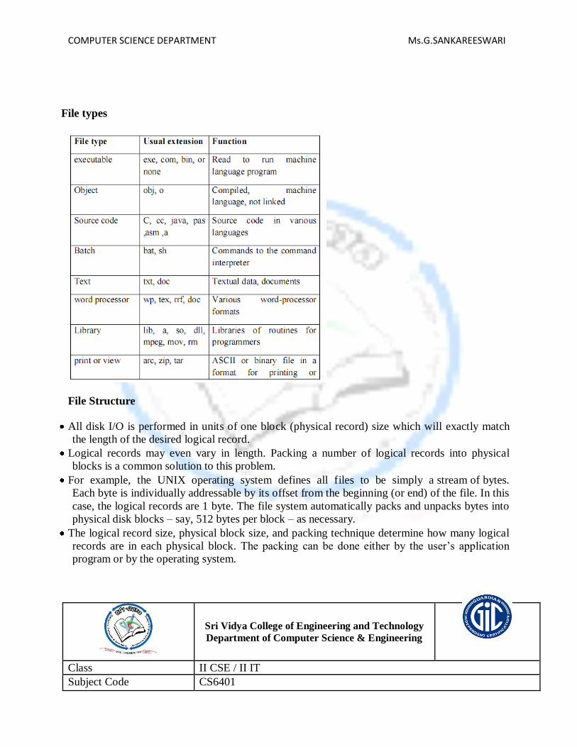
COMPUTER SCIENCE DEPARTMENT Ms.G.SANKAREESWARI
File types
File Structure
All disk I/O is performed in units of one block (physical record) size which will exactly match
the length of the desired logical record.
Logical records may even vary in length. Packing a number of logical records into physical
blocks is a common solution to this problem.
For example, the UNIX operating system defines all files to be simply a stream of bytes.
Each byte is individually addressable by its offset from the beginning (or end) of the file. In this
case, the logical records are 1 byte. The file system automatically packs and unpacks bytes into
physical disk blocks – say, 512 bytes per block – as necessary.
The logical record size, physical block size, and packing technique determine how many logical
records are in each physical block. The packing can be done either by the user‘s application
program or by the operating system.
Sri Vidya College of Engineering and Technology
Department of Computer Science & Engineering
Class II CSE / II IT
Subject Code CS6401

COMPUTER SCIENCE DEPARTMENT Ms.G.SANKAREESWARI
Subject Operating Systems
Prepared By G.SANKAREESWARI
Lesson Plan for Access Methods
Time: 50 Minutes
Lesson. No 3/10
Topics to be covered
Access Methods
Skills addressed:
Listening
Objectives of this lesson plan:
To enable students to understand File Access Methods.
Outcome (s):
Able to apply various methods of accessing a file.
Link sheet:
What is a file?
What are the various file accessing methods?
Evocation:
Lecture notes (attached)
Text Book Abraham Silberschatz, Peter Baer Galvin and Greg Gagne, “Operating System Concepts”, 9th
Edition, John Wiley and Sons Inc., 2012.
Application
File System Applications
Access Methods
1. Sequential Access
The simplest access method is sequential access. Information in the file is processed in order,
one record after the other. This mode of access is by far the most common; for example,
editors and compilers usually access files in this fashion. The bulk of the operations on a

COMPUTER SCIENCE DEPARTMENT Ms.G.SANKAREESWARI
file is reads and writes. A read operation reads the next portion of the file and automatically
advances a file pointer, which tracks the I/O location. Similarly, a write appends to the end
of the file and advances to the end of the newly written material (the new end of file). Such a
file can be reset to the beginning and, on some systems, a program may be able to skip forward
or back ward n records, for some integer n-perhaps only for n=1. Sequential access is
based on a tape model of a file, and works as well on sequential-access devices as it does
on random – access ones.
2. Direct Access
Another method is direct access (or relative access). A file is made up of fixed length logical
records that allow programs to read and write records rapidly in no particular order. The direct-
access methods is based on a disk model of a file, since disks allow random access to any file
block. For direct access, the file is viewed as a numbered sequence of blocks or records. A
direct-access file allows arbitrary blocks to be read or written. Thus, we may read block 14,
then read block 53, and then write block7. There are no restrictions on the order of reading
or writing for a direct-access file. Direct – access files are of great use for immediate access to
large amounts of information. Database is often of this type. When a query concerning a
particular subject arrives, we compute which block contains the answer, and then read that block
directly to provide the desired information.
As a simple example, on an air line – reservation system, we might store all the information
about a particular flight (for example, flight 713) in the block identified by the flight
number. Thus, the number of available seats for flight 713 is stored in block 713 of the
reservation file. To store information about a larger set, such as people, we might compute a
hash function on the people‘s names, or search a small in- memory index to determine a
block to read and search.
3. Other Access methods
Other access methods can be built on top of a direct – access method these methods generally
involve the construction of an index for the file. The index like an index in the back of a book

COMPUTER SCIENCE DEPARTMENT Ms.G.SANKAREESWARI
contains pointers to the various blocks in find a record in the file. We first search the index, and
then use the pointer to access the file directly and the find the desired record.
With large files, the index file itself may become too large to be kept in memory. One
solution is to create an index for the index file. The primary index file would contain pointers
to secondary index tiles, which would point to the actual data items.
Sri Vidya College of Engineering and Technology Department of Computer Science & Engineering
Class II CSE / II IT
Subject Code CS6401
Subject Operating Systems
Prepared By G.SANKAREESWARI
Lesson Plan for Directory Structure
Time: 50 Minutes
Lesson. No 4/10
Topics to be covered
Directory Structure
Skills addressed:
Listening
Objectives of this lesson plan:
To enable students to understand directory structure in the operating system.
Outcome (s):
Able to apply directory system in the real time systems.
Link sheet:
What is directory?
What is the purpose of ‗dir‘ command in DOS?
Evocation:
Lecture notes (attached)
Text Book

COMPUTER SCIENCE DEPARTMENT Ms.G.SANKAREESWARI
Abraham Silberschatz, Peter Baer Galvin and Greg Gagne, ―Operating System
Concepts‖, 9th Edition, John Wiley and Sons Inc., 2012.
Application
Linux File Systems
Directory Structure
There are five directory structures. They are
Single-level directory
Two-level directory
Tree-Structured directory
Acyclic Graph directory
General Graph directory
1. Single – Level Directory
The simplest directory structure is the single- level directory. All files are contained in the same
directory.
Disadvantage:
When the number of files increases or when the system has more than one user, since all
files are in the same directory, they must have unique names.
2. Two – Level Directory
In the two level directory structures, each user has her own user file directory
(UFD).
When a user job starts or a user logs in, the system‘s master file directory
(MFD) is searched. The MFD is indexed by user name or account number, and each
entry points to the UFD for that user.
When a user refers to a particular file, only his own UFD is searched.
Thus, different users may have files with the same name.
Although the two – level directory structure solves the name-collision problem
Disadvantage:
Users cannot create their own sub-directories.
3. Tree – Structured Directory
A tree is the most common directory structure.
The tree has a root directory. Every file in the system has a unique path name.
A path name is the path from the root, through all the subdirectories to a specified file.
A directory (or sub directory) contains a set of files or sub directories.
A directory is simply another file. But it is treated in a special way.
All directories have the same internal format.
One bit in each directory entry defines the entry as a file (0) or as a subdirectory (1).
Special system calls are used to create and delete directories.
Path names can be of two types: absolute path names or relative path names.

COMPUTER SCIENCE DEPARTMENT Ms.G.SANKAREESWARI
An absolute path name begins at the root and follows a path down to the specified file,
giving the directory names on the path.
A relative path name defines a path from the current directory.
4. Acyclic Graph Directory.
An acyclic graph is a graph with no cycles.
To implement shared files and subdirectories this directory structure is used.
An acyclic – graph directory structure is more flexible than is a simple tree structure, but it is
also more complex. In a system where sharing is implemented by symbolic link, this
situation is somewhat easier to handle. The deletion of a link does not need to affect the
original file; only the link is removed.
Another approach to deletion is to preserve the file until all references to it are deleted. To
implement this approach, we must have some mechanism for determining that the last
reference to the file has been deleted.

COMPUTER SCIENCE DEPARTMENT Ms.G.SANKAREESWARI
Sri Vidya College of Engineering and Technology Department of Computer Science & Engineering
Class II CSE / II IT
Subject Code CS6401
Subject Operating Systems
Prepared By G.SANKAREESWARI
Lesson Plan for File System Mounting – Protection
Time: 50 Minutes
Lesson. No 5/10
Topics to be covered
File System Mounting – Protection
Skills addressed:
Listening
Objectives of this lesson plan:
To enable students to understand the file system mounting and protection.
Outcome (s):
Able to apply the protection on files to improve security.
Link sheet:
What is file?
What is partition of OS?
Evocation:

COMPUTER SCIENCE DEPARTMENT Ms.G.SANKAREESWARI
Lecture notes (attached)
Text Book
Abraham Silberschatz, Peter Baer Galvin and Greg Gagne, ―Operating System
Concepts‖, 9th Edition, John Wiley and Sons Inc., 2012.
Application
Security
File System Mounting
Just as a file must be opened before it is used, a file system must be mounted before it can
be available to processes on the system.
The mount procedure is straightforward. The operating system is given the name of the
device, and the location within the file structure at which to attach the File system (or
mount point).
A mount point is an empty directory at which the mounted file system will be attached.
For instance, on a UNIX system, a file system containing user‘s home directories
might be mounted as /home; then to access the directory structure within that file system ,
one could precede the directory names with /home, as in /home/jane.
Mounting that file system under /user would result in the pathname/users/jane
The operating system verifies that the devices contain a valid file system.
It does so by asking the device driver to read the device directory and verifying
that the directory was the expected format.
Finally, the operating system notes in its directory structure that a file system is
mounted at the specified mount point.
File Sharing
1. Multiple Users
When an operating system accommodates multiple users, the issues of file sharing, file
naming and file protection become preeminent.
The system either can allow user to access the file of other users by default, or it may
require that a user specifically grant access to the files.
These are the issues of access control and protection.
To implementing sharing and protection, the system must maintain more file and
directory attributes than a on a single-user system.
The owner is the user who may change attributes, grand access, and has the most control
over the file or directory.

COMPUTER SCIENCE DEPARTMENT Ms.G.SANKAREESWARI
The group attribute of a file is used to define a subset of users who may share access to
the file.
Most systems implement owner attributes by managing a list of user names and
associated user identifiers (user Ids).
When a user logs in to the system, the authentication stage determines the appropriate
user ID for the user. That user ID is associated with all of user‘s processes and threads.
When they need to be user readable, they are translated, back to the user name via
the user name list.
Likewise, group functionality can be implemented as a system wide list of group names
and group identifiers. Every user can be in one or more groups, depending upon operating
system design decisions. The user‘s group Ids is also included in every associated
process and thread.
2. Remote File System
Networks allowed communications between remote computers.
Networking allows the sharing or resource spread within a campus or even around the
world.
User manually transfer files between machines via programs like ftp.
A distributed file system (DFS) in which remote directories is visible from the local
machine.
The World Wide Web: A browser is needed to gain access to the remote file and
separate operations (essentially a wrapper for ftp) are used to transfer files.
a) The client-server Model:
Remote file systems allow a computer to a mount one or more file systems from one
or more remote machines.
A server can serve multiple clients, and a client can use multiple servers,
depending on the implementation details of a given client –server facility.
Client identification is more difficult. Clients can be specified by their network name
or other identifier, such as IP address, but these can be spoofed (or imitate).
An unauthorized client can spoof the server into deciding that it is authorized, and the
unauthorized client could be allowed access.
b) Distributed Information systems:
Distributed information systems, also known as distributed naming service, have been
devised to provide a unified access to the information needed for remote computing.
Domain name system (DNS) provides host-name-to-network address translations for
their entire Internet (including the World Wide Web).
Before DNS was invented and became widespread, files containing the same
information were sent via e-mail of ftp between all networked hosts.
c) Failure Modes:
Redundant arrays of inexpensive disks (RAID) can prevent the loss of a disk from
resulting in the loss of data.
Remote file system has more failure modes. By nature of the complexity of
networking system and the required interactions between remote machines, many
more problems can interfere with the proper operation of remote file systems.
d) Consistency Semantics:
It is characterization of the system that specifies the semantics of multiple users
accessing a shared file simultaneously.

COMPUTER SCIENCE DEPARTMENT Ms.G.SANKAREESWARI
These semantics should specify when modifications of data by one user are
observable by other users.
The semantics are typically implemented as code with the file system.
A series of file accesses (that is reads and writes) attempted by a user to the same file
is always enclosed between the open and close operations.
The series of access between the open and close operations is a file session.
(i) UNIX Semantics:
The UNIX file system uses the following consistency semantics:
1. Writes to an open file by a user are visible immediately to other users that have this file
open at the same time.
2. One mode of sharing allows users to share the pointer of current location into the
file. Thus, the advancing of the pointer by one user affects all sharing users.
(ii) Session Semantics:
The Andrew file system (AFS) uses the following consistency semantics:
1. Writes to an open file by a user are not visible immediately to other users that have the
same file open simultaneously.
2. Once a file is closed, the changes made to it are visible only in sessions starting
later. Already open instances of the file do not reflect this change.
(iii) Immutable –shared File Semantics:
1. Once a file is declared as shared by its creator, it cannot be modified.
2. Its name may not be reused and its contents may not be altered.
File Protection
(i) Need for file protection
When information is kept in a computer system, we want to keep it safe from
physical damage (reliability) and improper access (protection).
Reliability is generally provided by duplicate copies of files. Many computers have
systems programs that automatically (or though computer-operator intervention) copy
disk files to tape at regular intervals (once per day or week or month) to maintain a
copy should a file system be accidentally destroyed.
File systems can be damaged by hardware problems (such as errors in reading or
writing), power surges or failures, head crashes, dirt, temperature extremes, and
vandalism. Files may be deleted accidentally. Bugs in the file-system software can also
cause file contents to be lost.
Protection can be provided in many ways. For a small single-user system, we might
provide protection by physically removing the floppy disks and locking them in a
desk drawer or file cabinet. In a multi-user system, however, other mechanisms are
needed.
(ii) Types of Access
Complete protection is provided by prohibiting access.
Free access is provided with no protection.
Both approaches are too extreme for general use.
What is needed is controlled access.
Protection mechanisms provide controlled access by limiting the types of file access that
can be made. Access is permitted or denied depending on several factors, one of which is the
type of access requested. Several different types of operations may be controlled:
1. Read: Read from the file.
2. Write: Write or rewrite the file.
3. Execute: Load the file into memory and execute it.

COMPUTER SCIENCE DEPARTMENT Ms.G.SANKAREESWARI
4. Append: Write new information at the end of the file.
5. Delete: Delete the file and free its space for possible reuse.
6. List: List the name and attributes of the file.
(iii) Access Control
Associate with each file and directory an access-control list (ACL) specifying the user
name and the types of access allowed for each user.
When a user requests access to a particular file, the operating system checks the access
list associated with that file. If that user is listed for the requested access, the access is
allowed. Otherwise, a protection violation occurs and the user job is denied access to the
file.
This technique has two undesirable consequences:
Constructing such a list may be a tedious and unrewarding task, especially if we do
not know in advance the list of users in the system.
The directory entry, previously of fixed size, now needs to be of variable size,
resulting in more complicated space management.
To condense the length of the access control list, many systems recognize three classifications of
users in connection with each file:
Owner: The user who created the file is the owner.
Group: A set of users who are sharing the file and need similar access is a group, or
work group.
Universe: All other users in the system constitute the universe.
Sri Vidya College of Engineering and Technology Department of Computer Science & Engineering
Class II CSE / II IT
Subject Code CS6401
Subject Operating Systems
Prepared By G.SANKAREESWARI
Lesson Plan for File System Implementation
Time: 50 Minutes
Lesson. No 6/10
Topics to be covered
File System Implementation
Skills addressed:
Listening
Objectives of this lesson plan:
To enable students to understand the implementation of file system.
Outcome (s):
Able to explain the file system and its implementation.
Link sheet:
What is directory?
What is kernel?

COMPUTER SCIENCE DEPARTMENT Ms.G.SANKAREESWARI
Evocation:
Lecture notes (attached)
Text Book
Abraham Silberschatz, Peter Baer Galvin and Greg Gagne, ―Operating System
Concepts‖, 9th Edition, John Wiley and Sons Inc., 2012.
Application
Windows and Linux
File System Structure
Disk provides the bulk of secondary storage on which a file system is maintained.
Characteristics of a disk
They can be rewritten in place; it is possible to read a block from the disk, to modify the
block and to write it back into the same place.
They can access directly any given block of information to the disk.
To produce an efficient and convenient access to the disk, the operating system imposes one or
more file system to allow the data to be stored, located and retrieved easily. The file
system itself is generally composed of many different levels. Each level in the design uses the
features of lower level to create new features for use by higher levels.
Layered File System
The I/O control consists of device drivers and interrupts handlers to transfer information
between the main memory and the disk system.
The basic file system needs only to issue generic commands to the appropriate device
driver to read and write physical blocks on the disk. Each physical block is identified by
its numeric disk address (for example, drive –1, cylinder 73, track 2, sector 10)

COMPUTER SCIENCE DEPARTMENT Ms.G.SANKAREESWARI
The file-organization module knows about file and their logical blocks, as well as physical
blocks. By knowing the type of file allocation used and the location of the file, the file
organization module can translate logical block address to physical block addresses for the basic
fie system to transfer. The file-organization module also includes the free-space manager, which
tracks unallocated blocks and provides these blocks to the file-organization module when
requested.
The logical file system manages metadata information. Metadata includes all of the file-system
structure, excluding the actual data (or contents of the files). The logical file system manages the
directory structure to provide the file-organization module with the information the latter needs,
given a symbolic file name. It maintains file structure, via file control blocks. A file control
block (FCB) contains information about the file , including ownership, permissions, and
location of the file contents. The logical file system is also responsible for protection and
security.
File System Implementation
Several-on-disk and in-memory structures are used to implement a file system
The on-disk structures include:
1. A boot control block can contain information needed by the system to boot an operating from
that partition. If the disk does not contain an operating System, this block can be empty. It is
typically the first block of a partition. In UFS, this is called the boot block; In NTFS, it is
partition boot sector.
2. A partition control block contains partition details such as the number of blocks in the
partition, size of the blocks, free-block count and free block pointers and free FCB count
and FCB pointers. In UFS this is called a super block; in NTFS, it is the Master File Table.
3. A directory structure is used to organize the files.
4. An FCB contains many of the files details, including file permissions, ownership, size and
location of the data blocks. IN UFS this called the inode. In NTFS, this information‘s actually
stored within the Master File Table, which uses a relational database structure, with a row per
file.
The in-memory structures include:
1. An in-memory partition table containing, information about each mounted partition.
2. An in-memory directory structures that hold s the directory information of recently accessed
directories.
3. The system-wide open-file table contains a copy of the FCB of each open files, as well
as other information.
4. The per-process open-file table contains a pointer tot eh appropriate entry in the systems-wide
open file table, as well as other information.

COMPUTER SCIENCE DEPARTMENT Ms.G.SANKAREESWARI
Sri Vidya College of Engineering and Technology
Department of Computer Science & Engineering
Class II CSE / II IT
Subject Code CS6401
Subject Operating Systems
Prepared By G.SANKAREESWARI
Lesson Plan for Directory implementation – Allocation methods
Time: 50 Minutes
Lesson. No 7/10
Topics to be covered
Directory implementation – Allocation methods
Skills addressed:
Listening
Objectives of this lesson plan:
To enable students to understand the directory implementation and allocation
methods.
Outcome (s):
Able to explain the directory implementation and allocation methods.
Link sheet:
What is file?
What is directory?
Evocation:

COMPUTER SCIENCE DEPARTMENT Ms.G.SANKAREESWARI
Lecture notes (attached)
Text Book Abraham Silberschatz, Peter Baer Galvin and Greg Gagne, “Operating System Concepts”, 9th
Edition, John Wiley and Sons Inc., 2012.
Application
Linux
Directory Implementation
1. Linear List
The simplest method of implementing a directory is to use a linear list of file names with
pointer to the data blocks.
A linear list of directory entries requires a linear search to find a particular entry.
This method is simple to program but time- consuming to execute. To create a new file,
we must first search the but time – consuming to execute.
The real disadvantage of a linear list of directory entries is the linear search to find a file.
2. Hash Table
In this method, a linear list stores the directory entries, but a hash data structure is
also used.
The hash table takes a value computed from the file name and returns a pointer to
the file name in the linear list.
Therefore, it can greatly decrease the directory search time.
Insertion and deleting are also fairly straight forward, although some provision must
be made for collisions – situation where two file names hash to the same location.
The major difficulties with a hash table are its generally fixed size and the dependence of
the hash function on that size.

COMPUTER SCIENCE DEPARTMENT Ms.G.SANKAREESWARI
Allocation Methods
The main problem is how to allocate space to these files so that disk space is utilized effectively
and files can be accessed quickly.
There are three major methods of allocating disk space:
1. Contiguous Allocation
2. Linked Allocation
3. Indexed Allocation
1. Contiguous Allocation
The contiguous allocation method requires each file to occupy a set of contiguous blocks
on the disk.
Contiguous allocation of a file is defined by the disk address and length (in block units)
of the first block. If the file is n blocks long and starts at location b, then it occupies
blocks b, b+1, b+2… b+n-1.
The directory entry for each file indicates the address of the starting block and the length
of the area allocated for this file.
Disadvantages
1. Finding space for a new file.
The contiguous disk space-allocation problem suffers from the problem of external
fragmentation. As file are allocated and deleted, the free disk space is broken into chunks. It
becomes a problem when the largest contiguous chunk is insufficient for a request; storage is
fragmented into a number of holes, no one of which is large enough to store the data.
2. Determining how much space is needed for a file.
When the file is created, the total amount of space it will need must be found an allocated
how does the creator know the size of the file to be created? If we allocate too little
space to a file, we may find that file cannot be extended. The other possibility is to
find a larger hole, copy the contents of the file to the new space, and release the
previous space. This series of actions may be repeated as long as space exists, although
it can be time – consuming. However, in this case, the user never needs to be
informed explicitly about what is happening ; the system continues despite the
problem, although more and more slowly.
Even if the total amount of space needed for a file is known in advance pre-allocation
may be inefficient.
A file that grows slowly over a long period (months or years) must be allocated
enough space for its final size, even though much of that space
may be unused for a long time the file, therefore has a large amount of internal
fragmentation.
To overcome these disadvantages
Use a modified contiguous allocation scheme, in which a contiguous chunk of space
called as an extent is allocated initially and then, when that amount is not large enough
another chunk of contiguous space an extent is added to the initial allocation.
Internal fragmentation can still be a problem if the extents are too large, and external
fragmentation can be a problem as extents of varying sizes are allocated and
deallocated.

COMPUTER SCIENCE DEPARTMENT Ms.G.SANKAREESWARI
2. Linked Allocation
Linked allocation solves all problems of contiguous allocation.
With linked allocation, each file is a linked list of disk blocks, the disk blocks
may be scattered anywhere on the disk.
The directory contains a pointer to the first and last blocks of the file. For example, a file
of five blocks might start at block 9, continue at block 16, then block 1, block 10, and
finally bock 25.
Each block contains a pointer to the next block. These pointers are not made available to
the user.
There is no external fragmentation with linked allocation, and any free block on the free
space list can be used to satisfy a request.
The size of a file does not need to the declared when that file is created. Afile can
continue to grow as long as free blocks are available consequently, it is never necessary
to compacts disk space.
Disadvantages
1. Used effectively only for sequential access files
To find the ith block of a file, we must start at the beginning of that file, and follow the
pointers until we get to the ith block. Each access to a pointer requires a disk read, and
sometimes a disk seek consequently; it is inefficient to support a direct- access capability for
linked allocation files.
2. Space required for the pointers
If a pointer requires 4 bytes out of a 512-byte block, then 0.78 percent of the disk is being used
for pointers, rather than for information. Solution to this problem is to collect blocks into
multiples, called clusters, and to allocate the clusters rather than blocks. For instance, the file
system may define clusters as 4 blocks, and operate on the disk in only cluster units.
3. Reliability
Since the files are linked together by pointers scattered all over the disk hardware
failure might result in picking up the wrong pointer. This error could result in linking into
the free- space list or into another file. Partial solution are to use doubly linked lists or to store
the file names in a relative block number in each block; however, these schemes require even
more over head for each file.
File Allocation Table (FAT)
An important variation on the linked allocation method is the use of a file allocation table
(FAT).
This simple but efficient method of disk- space allocation is used by the MS-DOS and
OS/2 operating systems.
A section of disk at beginning of each partition is set aside to contain the table.
The table has entry for each disk block, and is indexed by block number.
The FAT is much as is a linked list.
The directory entry contains the block number the first block of the file.
The table entry indexed by that block number contains the block number of the next
block in the file.
This chain continues until the last block which has a special end – of – file value as the
table entry.
Unused blocks are indicated by a 0 table value.

COMPUTER SCIENCE DEPARTMENT Ms.G.SANKAREESWARI
Allocating a new block file is a simple matter of finding the first 0 – valued table entry,
and replacing the previous end of file value with the address of the new block.
The 0 is replaced with the end – of – file value; an illustrative example is the FAT
structure for a file consisting of disk blocks 217,618, and 339.
3. Indexed Allocation
Linked allocation solves the external – fragmentation and size- declaration problems of
contiguous allocation.
Linked allocation cannot support efficient direct access, since the pointers to the blocks
are scattered with the blocks themselves all over the disk and need to be retrieved in
order.
Indexed allocation solves this problem by bringing all the pointers together into one
location: the index block.
Each file has its own index block, which is an array of disk – block addresses.
The ith entry in the index block points to the ith block of the file. The directory
contains the address of the index block.
To read the ith block, we use the pointer in the ith index – block entry to find and read the
desired block this scheme is similar to the paging scheme.
When the file is created, all pointers in the pointers in the index block are set to nil. When
the ith block is first written, a block is obtained from the free space manager, and its
address is put in the ith index – block entry.
Indexed allocation supports direct access, without suffering from external fragmentation,
because any free block on the disk may satisfy a request for more space.
Disadvantages
1. Pointer Overhead
Indexed allocation does suffer from wasted space. The pointer over head of the index block
is generally greater than the pointer over head of linked allocation.
2. Size of Index block
If the index block is too small, however, it will not be able to hold enough pointers for a
large file, and a mechanism will have to be available to deal with this issue:
Linked Scheme
An index block is normally one disk block. Thus, it can be read and written directly by itself. To
allow for large files, we may link together several index blocks.
Multilevel index
A variant of the linked representation is to use a first level index block to point to a set of second
level index blocks.
Combined scheme
Another alternative, used in the UFS, is to keep the first, say, 15 pointers of the
index block in the file‘s inode.

COMPUTER SCIENCE DEPARTMENT Ms.G.SANKAREESWARI
The first 12 of these pointers point to direct blocks; that is for small ( no more than 12
blocks) files do not need a separate index block
The next pointer is the address of a single indirect block.
The single indirect block is an index block, containing not data, but rather the addresses
of blocks that do contain data.
Then there is a double indirect block pointer, which contains the address of a block
that contain pointers to the actual data blocks. The last pointer would contain pointers to
the actual data blocks.
The last pointer would contain the address of a triple indirect block.
Sri Vidya College of Engineering and Technology
Department of Computer Science & Engineering
Class II CSE / II IT
Subject Code CS6401
Subject Operating Systems
Prepared By G.SANKAREESWARI
Lesson Plan for Free-space Management, Efficiency & Performance
Time: 50 Minutes
Lesson. No 8/10
Topics to be covered
Free-space Management, Efficiency & Performance
Skills addressed:
Listening
Objectives of this lesson plan:
To enable students to understand the free-space management, efficiency & performance.
Outcome (s):
Able to apply the free space management and efficiency performance in files.
Link sheet:
What is efficiency?
What is partitioning of disk?
Evocation:

COMPUTER SCIENCE DEPARTMENT Ms.G.SANKAREESWARI
Lecture notes (attached)
Text Book Abraham Silberschatz, Peter Baer Galvin and Greg Gagne, “Operating System Concepts”, 9th
Edition, John Wiley and Sons Inc., 2012.
Application
Memory Management Applications
Free-space Management
Since disk space is limited, we need to reuse the space from deleted files for new files, if
possible.
To keep track of free disk space, the system maintains a free-space list.
The free-space list records all free disk blocks – those not allocated to some file or
directory.
To create a file, we search the free-space list for the required amount of space, and
allocate that space to the new file.
This space is then removed from the free-space list.
When a file is deleted, its disk space is added to the free-space list.
1. Bit Vector
The free-space list is implemented as a bit map or bit vector.
Each block is represented by 1 bit. If the block is free, the bit is 1; if the block is allocated,
the bit is 0.
For example, consider a disk where block 2,3,4,5,8,9,10,11,12,13,17,18,25,26 and 27 are
free, and the rest of the block are allocated. The free space bit map would be
001111001111110001100000011100000.
The main advantage of this approach is its relatively simplicity and efficiency in
finding the first free block, or n consecutive free blocks on the disk.
2. Linked List
Another approach to free-space management is to link together all the free disk
blocks, keeping a pointer to the first free block in a special location on the disk and
caching it in memory.
This first block contains a pointer to the next free disk block, and so on.
In our example, we would keep a pointer to block 2, as the first free block. Block 2
would contain a pointer to block 3, which would point to block 4, which would point
to block 5, which would point to block 8, and so on.
However, this scheme is not efficient; to traverse the list, we must read each block,
which requires substantial I/O time.
The FAT method incorporates free-block accounting data structure. No separate
method is needed.
3. Grouping
A modification of the free-list approach is to store the addresses of n free blocks in
the first free block.
The first n-1 of these blocks is actually free.
The last block contains the addresses of other n free blocks, and so on.

COMPUTER SCIENCE DEPARTMENT Ms.G.SANKAREESWARI
The importance of this implementation is that the addresses of a large number
of free blocks can be found quickly.
4. Counting
We can keep the address of the first free block and the number n of free
contiguous blocks that follow the first block.
Each entry in the free-space list then consists of a disk address and a count.
Although each entry requires more space than would a simple disk address, the
overall list will be shorter, as long as the count is generally greater than 1
Efficiency & Performance
Efficiency dependent on:
o disk allocation and directory algorithms
o types of data kept in file‘s directory entry
Performance
o disk cache – separate section of main memory for frequently used blocks
o free-behind and read-ahead – techniques to optimize sequential access
o improve PC performance by dedicating section of memory as virtual disk, or RAM disk
Page Cache
A page cache caches pages rather than disk blocks using virtual memory techniques
Memory-mapped I/O uses a page cache
Routine I/O through the file system uses the buffer (disk) cache
This leads to the following figure
I/O Without a Unified Buffer Cache
Unified Buffer Cache
A unified buffer cache uses the same page cache to cache both memory-mapped
pages and ordinary file system I/O
I/O Using a Unified Buffer Cache

COMPUTER SCIENCE DEPARTMENT Ms.G.SANKAREESWARI
Sri Vidya College of Engineering and Technology
Department of Computer Science & Engineering
Class II CSE / II IT
Subject Code CS6401
Subject Operating Systems
Prepared By G.SANKAREESWARI
Lesson Plan for Recovery, Log-Structured File Systems
Time: 50 Minutes
Lesson. No 9/10
Topics to be covered
Recovery and Log-Structured File Systems
Skills addressed:
Listening
Objectives of this lesson plan:
To enable students to understand the Recovery, Log-Structured File Systems.
Outcome (s):
Able to apply the recovery options in the file system.
Link sheet:
What is recovery?
Evocation:

COMPUTER SCIENCE DEPARTMENT Ms.G.SANKAREESWARI
Lecture notes (attached)
Text Book
Abraham Silberschatz, Peter Baer Galvin and Greg Gagne, ―Operating System
Concepts‖, 9th Edition, John Wiley and Sons Inc., 2012.
Application
Backup
Recovery
Files and directories are kept both in main memory and on disk, and care must be taken to
ensure that system failure does not result in loss of data or in data inconsistency.
1. Consistency Checking
The directory information in main memory is generally more up to date than is the
corresponding information on the disk, because cached directory information is
not necessarily written to disk as soon as the update takes place.
Frequently, a special program is run at reboot time to check for and correct disk
inconsistencies.
The consistency checker—a systems program such as chkdsk in MS-DOS—compares
the data in the directory structure with the data blocks on disk and tries to fix any
inconsistencies it finds. The allocation and free-space-management algorithms
dictate what types of problems the checker can find and how successful it will be in
fixing them.
2. Backup and Restore
Magnetic disks sometimes fail, and care must be taken to ensure that the data lost in
such a failure are not lost forever. To this end, system programs can be used to back
up data from disk to another storage device, such as a floppy disk, magnetic tape,
optical disk, or other hard disk.
Recovery from the loss of an individual file, or of an entire disk, may then be a matter
of restoring the data from backup.
A typical backup schedule may then be as follows:
Day 1: Copy to a backup medium all files from the disk. This is called a full backup.
Day 2: Copy to another medium all files changed since day 1. This is an incremental
backup.
Day 3: Copy to another medium all files changed since day 2.

COMPUTER SCIENCE DEPARTMENT Ms.G.SANKAREESWARI
Day N: Copy to another medium all files changed since day N— 1. Then go back to Day 1.
Log-Structured File Systems
Computer scientists often find that algorithms and technologies originally used in one
area are equally useful in other areas.
These logging algorithms have been applied successfully to the problem of
consistency checking.
The resulting implementations are known as log-based transaction-oriented (or
journaling) file systems.
Fundamentally, all metadata changes are written sequentially to a log.
Each set of operations for performing a specific task is a transaction.
Once the changes are written to this log, they are considered to be committed,
and the system call can return to the user process, allowing it to continue execution.
As the changes are made, a pointer is updated to indicate which actions have
completed and which are still incomplete.
When an entire committed transaction is completed, it is removed from the log file,
which is actually a circular buffer.
A circular buffer writes to the end of its space and then continues at the
beginning, overwriting older values as it goes. If the system crashes, the log file will
contain zero or more transactions.

UNIT V CASE STUDY 9Linux System- Basic Concepts;System Administration-Requirements for Linux SystemAdministrator,Setting up a LINUX Multifunction Server, Domain Name System, Setting Up LocalNetwork Services;Virtualization- Basic Concepts, Setting Up Xen,VMware on Linux Host andAdding Guest OS.
Textbook:
1. Abraham Silberschatz, Peter Baer Galvin and Greg Gagne, “Operating System Concepts”, 9 th
Edition, John Wiley and Sons Inc., 2012.
Lesson Plan 1 Linux System- Administration-Requirements
Lesson Plan 2 Setting up a LINUX Multifunction
Lesson Plan 3 Server, Domain Name System
Lesson Plan 4 Setting Up Local Network Services; Virtualization
Lesson Plan 5 Setting Up Xen,
Lesson Plan 6 VMware on Linux Host and Adding Guest OS.
Lesson Plan 7 Review
Staff in-charge HOD-CSE
Sri Vidya College of Engineering and Technology
Virudhunagar – 626 005
Department of Computer Science and EngineeringClass: II CSE, V Semester
Subject Code: Cs6401
Subject: Operating Systems
Prepared by G.Sankareeswari

Linux ( i/ l̍ɪnəks/ LIN-uks[5][6] or, less frequently used, / l̍aɪnəks/ LYN-uks)[6][7] is a Unix-like and mostly POSIX-compliant[8] computer operating system assembled under the model offree and open-source software development and distribution. The defining component of Linuxis the Linux kernel,[9] an operating system kernel first released on 5 October 1991 by LinusTorvalds.[10][11] The Free Software Foundation uses the name GNU/Linux to describe theoperating system, which has led to some controversy.[12][13]
Linux was originally developed as a free operating system for Intel x86–based personalcomputers, but has since been ported to more computer hardware platforms than any otheroperating system.[citation needed] It is the leading operating system on servers and other big ironsystems such as mainframe computers and supercomputers,[14][15][16] but is used on only around1% of desktop computers.[17] Linux also runs on embedded systems, which are devices whoseoperating system is typically built into the firmware and is highly tailored to the system; thisincludes mobile phones,[18] tablet computers, network routers, facility automation controls,televisions[19][20] and video game consoles. Android, the most widely used operating system fortablets and smartphones, is built on top of the Linux kernel.[21]
The development of Linux is one of the most prominent examples of free and open-sourcesoftware collaboration. The underlying source code may be used, modified, and distributed—commercially or non-commercially—by anyone under licenses such as the GNU General PublicLicense. Typically, Linux is packaged in a form known as a Linux distribution, for both desktopand server use. Some popular mainstream Linux distributions include Debian, Ubuntu, LinuxMint, Fedora, openSUSE, Arch Linux, and the commercial Red Hat Enterprise Linux and SUSELinux Enterprise Server. Linux distributions include the Linux kernel, supporting utilities andlibraries and usually a large amount of application software to fulfill the distribution's intendeduse.
A distribution oriented toward desktop use will typically include X11, Wayland or Mir as thewindowing system, and an accompanying desktop environment such as GNOME or the KDESoftware Compilation. Some such distributions may include a less resource intensive desktopsuch as LXDE or Xfce, for use on older or less powerful computers. A distribution intended torun as a server may omit all graphical environments from the standard install, and instead includeother software to set up and operate a solution stack such as LAMP. Because Linux is freelyredistributable, anyone may create a distribution for any intended use.
A Linux-based system is a modular Unix-like operating system. It derives much of its basicdesign from principles established in Unix during the 1970s and 1980s. Such a system uses amonolithic kernel, the Linux kernel, which handles process control, networking, and peripheraland file system access. Device drivers are either integrated directly with the kernel or added asmodules loaded while the system is running.[45]

Separate projects that interface with the kernel provide much of the system's higher-levelfunctionality. The GNU userland is an important part of most Linux-based systems, providingthe most common implementation of the C library, a popular CLI shell, and many of thecommon Unix tools which carry out many basic operating system tasks. The graphical userinterface (or GUI) used by most Linux systems is built on top of an implementation of the XWindow System.[46] More recently, the Linux community seeks to advance to Wayland as thenew display server protocol in place of X11; Ubuntu, however, develops Mir instead ofWayland.[47]
Various layers within Linux, also showing separation between the userland and kernel space
Usermode
User applicationsFor example, bash, LibreOffice, Apache OpenOffice, Blender, 0 A.D., MozillaFirefox, etc.
Low-level systemcomponents:
Systemdaemons:systemd, runit,logind,networkd,soundd...
Windowingsystem:X11, Wayland,Mir,SurfaceFlinger(Android)
Other libraries:GTK+, Qt, EFL, SDL, SFML, FLTK,GNUstep, etc.
Graphics:Mesa 3D,AMDCatalyst,...
C standard library
open(), exec(), sbrk(), socket(), fopen(), calloc(), ... (up to 2000subroutines)glibc aims to be POSIX/SUS-compatible, uClibc targets embedded systems,bionic written for Android, etc.
Kernelmode
Linux kernel
stat, splice, dup, read, open, ioctl, write, mmap, close, exit, etc.(about 380 system calls)The Linux kernel System Call Interface (SCI, aims to be POSIX/SUS-compatible)
Processschedulingsubsystem
IPCsubsystem
Memorymanagementsubsystem
Virtual filessubsystem
Networksubsystem
Other components: ALSA, DRI, evdev, LVM, device mapper, Linux NetworkScheduler, NetfilterLinux Security Modules: SELinux, TOMOYO, AppArmor, Smack
Hardware (CPU, main memory, data storage devices, etc.)
Installed components of a Linux system include the following:[46][48]

A bootloader, for example GNU GRUB, LILO, SYSLINUX, Coreboot or Gummiboot. This is aprogram that loads the Linux kernel into the computer's main memory, by being executed bythe computer when it is turned on and after the firmware initialization is performed.
An init program, such as the traditional sysvinit and the newer systemd, OpenRC and Upstart.This is the first process launched by the Linux kernel, and is at the root of the process tree: inother terms, all processes are launched through init. It starts processes such as system servicesand login prompts (whether graphical or in terminal mode).
Software libraries, which contain code that can be used by running processes. On Linux systemsusing ELF-format executable files, the dynamic linker that manages use of dynamic libraries isknown as ld-linux.so. If the system is set up for the user to compile software themselves,header files will also be included to describe the interface of installed libraries. Beside the mostcommonly used software library on Linux systems, the GNU C Library (glibc), there arenumerous other libraries.
o C standard library is the library needed to run standard C programs on a computersystem, with the GNU C Library being the most commonly used. Several alternatives areavailable, such as the EGLIBC (which was used by Debian for some time) and uClibc(which was designed for uClinux).
o Widget toolkits are the libraries used to build graphical user interfaces (GUIs) forsoftware applications. Numerous widget toolkits are available, including GTK+ andClutter (software) developed by the GNOME project, Qt developed by the Qt Projectand led by Digia, and Enlightenment Foundation Libraries (EFL) developed primarily bythe Enlightenment team.
User interface programs such as command shells or windowing environments.
User interface
Bash, a shell developed by GNU[49] and widely used in Linux
The user interface, also known as the shell, is either a command-line interface (CLI), a graphicaluser interface (GUI), or through controls attached to the associated hardware, which is commonfor embedded systems. For desktop systems, the default mode is usually a graphical userinterface, although the CLI is available through terminal emulator windows or on a separatevirtual console.
CLI shells are the text-based user interfaces, which use text for both input and output. Thedominant shell used in Linux is the GNU Bourne-Again Shell (bash), originally developed forthe GNU project. Most low-level Linux components, including various parts of the userland, usethe CLI exclusively. The CLI is particularly suited for automation of repetitive or delayed tasks,and provides very simple inter-process communication.
On desktop systems, the most popular user interfaces are the GUI shells, packaged together withextensive desktop environments, such as the K Desktop Environment (KDE), GNOME,Cinnamon, Unity, LXDE, Pantheon and Xfce, though a variety of additional user interfaces exist.Most popular user interfaces are based on the X Window System, often simply called "X". Itprovides network transparency and permits a graphical application running on one system to bedisplayed on another where a user may interact with the application; however, certain extensions

of the X Window System are not capable of working over the network.[50] Several popular Xdisplay servers exist, with the reference implementation, X.Org Server, being the most popular.
Different window managers variants exist for X11, including the tiling, dynamic, stacking andcompositing ones. Simpler X window managers, such as FVWM, Enlightenment, and WindowMaker, provide a minimalist functionality with respect to the desktop environments. A windowmanager provides a means to control the placement and appearance of individual applicationwindows, and interacts with the X Window System. The desktop environments include windowmanagers as part of their standard installations (Mutter for GNOME, KWin for KDE, Xfwm forxfce) although users may choose to use a different window manager if preferred.
Wayland is a display server protocol intended as a replacement for the aged X11 protocol; as of2014, Wayland has not received wider adoption. Unlike X11, Wayland does not need an externalwindow manager and compositing manager. Therefore, a Wayland compositor takes the role ofthe display server, window manager and compositing manager. Weston is the referenceimplementation of Wayland, while GNOME's Mutter and KDE's KWin are being ported toWayland as standalone display servers instead of merely compositing window managers.Enlightenment has already been successfully ported to Wayland since version 19.
Video input infrastructureMain article: Video4Linux
Linux currently has two modern kernel-userspace APIs for handing video input devices: V4L2API for video streams and radio, and DVB API for digital TV reception.[51]
Due to the complexity and diversity of different devices, and due to the large amount of formatsand standards handled by those APIs, this infrastructure needs to evolve to better fit otherdevices. Also, a good userspace device library is the key of the success for having userspaceapplications to be able to work with all formats supported by those devices.[52][53]
Development
Simplified history of Unix-like operating systems. Linux shares similar architecture and concepts (as partof the POSIX standard) but does not share non-free source code with the original Unix or MINIX.
Main articles: Linux distribution and Free software
The primary difference between Linux and many other popular contemporary operating systemsis that the Linux kernel and other components are free and open-source software. Linux is not theonly such operating system, although it is by far the most widely used.[54] Some free and open-source software licenses are based on the principle of copyleft, a kind of reciprocity: any workderived from a copyleft piece of software must also be copyleft itself. The most common freesoftware license, the GNU General Public License (GPL), is a form of copyleft, and is used forthe Linux kernel and many of the components from the GNU Project.
Linux based distributions are intended by developers for interoperability with other operatingsystems and established computing standards. Linux systems adhere to POSIX,[55] SUS,[56] LSB,

ISO, and ANSI standards where possible, although to date only one Linux distribution has beenPOSIX.1 certified, Linux-FT.[57][58]
Free software projects, although developed through collaboration, are often producedindependently of each other. The fact that the software licenses explicitly permit redistribution,however, provides a basis for larger scale projects that collect the software produced by stand-alone projects and make it available all at once in the form of a Linux distribution.
Many Linux distributions, or "distros", manage a remote collection of system software andapplication software packages available for download and installation through a networkconnection. This allows users to adapt the operating system to their specific needs. Distributionsare maintained by individuals, loose-knit teams, volunteer organizations, and commercialentities. A distribution is responsible for the default configuration of the installed Linux kernel,general system security, and more generally integration of the different software packages into acoherent whole. Distributions typically use a package manager such as dpkg, Synaptic, YAST,yum, or Portage to install, remove and update all of a system's software from one centrallocation.
CommunitySee also: Free software community and Linux User Group
A distribution is largely driven by its developer and user communities. Some vendors developand fund their distributions on a volunteer basis, Debian being a well-known example. Othersmaintain a community version of their commercial distributions, as Red Hat does with Fedoraand SUSE does with openSUSE.
In many cities and regions, local associations known as Linux User Groups (LUGs) seek topromote their preferred distribution and by extension free software. They hold meetings andprovide free demonstrations, training, technical support, and operating system installation to newusers. Many Internet communities also provide support to Linux users and developers. Mostdistributions and free software / open-source projects have IRC chatrooms or newsgroups.Online forums are another means for support, with notable examples being LinuxQuestions.organd the various distribution specific support and community forums, such as ones for Ubuntu,Fedora, and Gentoo. Linux distributions host mailing lists; commonly there will be a specifictopic such as usage or development for a given list.
There are several technology websites with a Linux focus. Print magazines on Linux ofteninclude cover disks including software or even complete Linux distributions.[59][60]
Although Linux distributions are generally available without charge, several large corporationssell, support, and contribute to the development of the components of the system and of freesoftware. An analysis of the Linux kernel showed 75 percent of the code from December 2008 toJanuary 2010 was developed by programmers working for corporations, leaving about 18 percentto volunteers and 7% unclassified.[61] Major corporations that provide contributions include Dell,IBM, HP, Oracle, Sun Microsystems (now part of Oracle), SUSE, and Nokia. A number of

corporations, notably Red Hat, Canonical, and SUSE, have built a significant business aroundLinux distributions.
The free software licenses, on which the various software packages of a distribution built on theLinux kernel are based, explicitly accommodate and encourage commercialization; therelationship between a Linux distribution as a whole and individual vendors may be seen assymbiotic. One common business model of commercial suppliers is charging for support,especially for business users. A number of companies also offer a specialized business version oftheir distribution, which adds proprietary support packages and tools to administer highernumbers of installations or to simplify administrative tasks.
Another business model is to give away the software in order to sell hardware. This used to bethe norm in the computer industry, with operating systems such as CP/M, Apple DOS andversions of Mac OS prior to 7.6 freely copyable (but not modifiable). As computer hardwarestandardized throughout the 1980s, it became more difficult for hardware manufacturers to profitfrom this tactic, as the OS would run on any manufacturer's computer that shared the samearchitecture.
Programming on Linux
Most Linux distributions support dozens of programming languages. The original developmenttools used for building both Linux applications and operating system programs are found withinthe GNU toolchain, which includes the GNU Compiler Collection (GCC) and the GNU buildsystem. Amongst others, GCC provides compilers for Ada, C, C++, Go and Fortran. Manyprogramming languages have a cross-platform reference implementation that supports Linux, forexample PHP, Perl, Ruby, Python, Java, Go, Rust and Haskell. First released in 2003, the LLVMproject provides an alternative cross-platform open-source compiler for many languages.Proprietary compilers for Linux include the Intel C++ Compiler, Sun Studio, and IBM XLC/C++ Compiler. BASIC in the form of Visual Basic is supported in such forms as Gambas,FreeBASIC, and XBasic, and in terms of terminal programming or QuickBASIC or TurboBASIC programming in the form of QB64.
A common feature of Unix-like systems, Linux includes traditional specific-purposeprogramming languages targeted at scripting, text processing and system configuration andmanagement in general. Linux distributions support shell scripts, awk, sed and make. Manyprograms also have an embedded programming language to support configuring or programmingthemselves. For example, regular expressions are supported in programs like grep, or locate,while advanced text editors, like GNU Emacs, have a complete Lisp interpreter built-in.
Most distributions also include support for PHP, Perl, Ruby, Python and other dynamiclanguages. While not as common, Linux also supports C# (via Mono), Vala, and Scheme. Anumber of Java Virtual Machines and development kits run on Linux, including the original SunMicrosystems JVM (HotSpot), and IBM's J2SE RE, as well as many open-source projects likeKaffe and JikesRVM.

GNOME and KDE are popular desktop environments and provide a framework for developingapplications. These projects are based on the GTK+ and Qt widget toolkits, respectively, whichcan also be used independently of the larger framework. Both support a wide variety oflanguages. There are a number of Integrated development environments available includingAnjuta, Code::Blocks, CodeLite, Eclipse, Geany, ActiveState Komodo, KDevelop, Lazarus,MonoDevelop, NetBeans, and Qt Creator, while the long-established editors Vim, nano andEmacs remain popular.[62]
Xen / z̍ɛn/ is a hypervisor using a microkernel design, providing services that allow multiplecomputer operating systems to execute on the same computer hardware concurrently.
The University of Cambridge Computer Laboratory developed the first versions of Xen. The Xencommunity develops and maintains Xen as free and open-source software, subject to therequirements of the GNU General Public License (GPL), version 2. Xen is currently available forthe IA-32, x86-64 and ARM instruction sets.
Software architecture
Xen runs in a more privileged CPU state than any other software on the machine.
Responsibilities of the hypervisor include memory management and CPU scheduling of allvirtual machines ("domains"), and for launching the most privileged domain ("dom0") - the onlyvirtual machine which by default has direct access to hardware. From the dom0 the hypervisorcan be managed and unprivileged domains ("domU") can be launched.[2]
The dom0 domain is typically a version of Linux, or BSD. User domains may either betraditional operating systems, such as Microsoft Windows under which privileged instructionsare provided by hardware virtualization instructions (if the host processor supports x86virtualization, e.g., Intel VT-x and AMD-V),[3] or para-virtualized operating system whereby theoperating system is aware that it is running inside a virtual machine, and so makes hypercallsdirectly, rather than issuing privileged instructions.
Xen boots from a bootloader such as GNU GRUB, and then usually loads a paravirtualized hostoperating system into the host domain (dom0).

Xen in Linux distributions and Linux upstream
Since version 3.0 of the Linux kernel, Xen support for dom0 and domU exists in the mainlinekernel.[33]
Uses
Internet hosting service companies use hypervisors to provide virtual private servers. AmazonEC2, IBM SoftLayer,[34] Liquid Web, Fujitsu Global Cloud Platform,[35] Linode, OrionVM[36]
and Rackspace Cloud use Xen as the primary VM hypervisor for their product offerings.[37]
Virtual machine monitors (also known as hypervisors) also often operate on mainframes andlarge servers running IBM, HP, and other systems.[citation needed] Server virtualization can providebenefits such as:
consolidation leading to increased utilization rapid provisioning dynamic fault tolerance against software failures (through rapid bootstrapping or rebooting) hardware fault tolerance (through migration of a virtual machine to different hardware) the ability to securely separate virtual operating systems the ability to support legacy software as well as new OS instances on the same computer
Xen's support for virtual machine live migration from one host to another allows workloadbalancing and the avoidance of downtime.
Virtualization also has benefits when working on development (including the development ofoperating systems): running the new system as a guest avoids the need to reboot the physicalcomputer whenever a bug occurs. Sandboxed guest systems can also help in computer-securityresearch, allowing study of the effects of some virus or worm without the possibility ofcompromising the host system.
Finally, hardware appliance vendors may decide to ship their appliance running several guestsystems, so as to be able to execute various pieces of software that require different operatingsystems.
Technology
Types of virtualization
Xen supports two different approaches to running the guest operating system. The choice ofapproach is up to the Xen hosting system administrator.
Paravirtualization - modified guests
Xen supports a form of virtualization known as paravirtualization, in which guests run amodified operating system. The guests are modified to use a special hypercall ABI, instead ofcertain architectural features.

Through paravirtualization, Xen can achieve high performance even on its host architecture(x86) which has a reputation for non-cooperation with traditional virtualization techniques.[38][39]
Xen can run paravirtualized guests ("PV guests" in Xen terminology) even on CPUs without anyexplicit support for virtualization.
Paravirtualization avoids the need to emulate a full set of hardware and firmware services, whichmakes a PV system simpler to manage and reduces the attack surface exposed to potentiallymalicious guests.
On 32-bit x86, the Xen host kernel code runs in Ring 0, while the hosted domains run in Ring 1(kernel) and Ring 3 (applications).
Hardware-assisted virtualization, allowing for unmodified guests
CPUs that support virtualization make it possible to support unmodified guests, includingproprietary operating systems (such as Microsoft Windows). This is known as hardware-assistedvirtualization, however in Xen this is known as hardware virtual machine (HVM).
HVM extensions provide additional execution modes, with an explicit distinction between themost-privileged modes used by the hypervisor with access to the real hardware (called "rootmode" in x86) and the less-privileged modes used by guest kernels and applications with"hardware" accesses under complete control of the hypervisor (in x86, known as "non-rootmode"; both root and non-root mode have Rings 0–3).
Both Intel and AMD have contributed modifications to Xen to support their respective Intel VT-x and AMD-V architecture extensions.[40] Support for ARM v7A and v8A virtualizationextensions came with Xen 4.3.[41]
HVM extensions also often offer new instructions to support direct calls by a paravirtualizedguest/driver into the hypervisor, typically used for I/O or other operations needing highperformance. These allow HVM guests with suitable minor modifications to gain many of theperformance benefits of paravirtualised I/O.
In current versions of Xen (up to 4.2) only fully virtualised HVM guests can make use ofhardware support for multiple independent levels of memory protection and paging. As a result,for some workloads, HVM guests with PV drivers (also known as PV-on-HVM, or PVH)provide better performance than pure PV guests.
Xen HVM has device emulation based on the QEMU project to provide I/O virtualization to thevirtual machines. The system emulates hardware via a patched QEMU "device manager" (qemu-dm) daemon running as a backend in dom0. This means that the virtualized machines see anemulated version of a fairly basic PC. In a performance-critical environment, PV-on-HVM diskand network drivers are used during normal guest operation, so that the emulated PC hardware ismostly used for booting.

Virtual machine migration
Administrators can "live migrate" Xen virtual machines between physical hosts across a LANwithout loss of availability. During this procedure, the LAN iteratively copies the memory of thevirtual machine to the destination without stopping its execution. The process requires a stoppageof around 60–300 ms to perform final synchronization before the virtual machine beginsexecuting at its final destination, providing an illusion of seamless migration. Similar technologycan serve to suspend running virtual machines to disk, "freezing" their running state forresumption at a later date.
Target Processors
The Xen hypervisor has been ported to a number of processor families.
Intelo IA-32, IA-64 (before version 4.2[42]), x86-64
PowerPCo Previously supported under the XenPPC project, no longer active after Xen 3.2[43]
ARMo Previously supported under the XenARM project for older versions of ARM without
virtualization extensions, such as the Cortex-A9o Currently supported since Xen 4.3 for newer versions of the ARM with virtualization
extensions, such as the Cortex-A15 MIPS
o XLP832 experimental port[44]
Scalability
Xen can scale to 4095 physical CPUs, 256 VCPUs per HVM guest, 512 VCPUs per PV guest,16 TB of RAM per host, and up to 1 TB of RAM per HVM guest or 512 GB of RAM per PVguest.[45]
Hosts
Xen can be shipped in a dedicated virtualization platform, such as Citrix XenServer EnterpriseEdition (formerly XenSource's XenEnterprise).
Alternatively, Xen is distributed as an optional configuration of many standard operatingsystems. Xen is available for and distributed with:
Alpine Linux offers a minimal Dom0 system (Busybox, UClibc) that can be run from removablemedia, like USB sticks.
Qubes OS for desktop usage openSUSE 10.x to 12.x;[46] only 64-bit hosts are supported since 12.1 SUSE Linux Enterprise Server (since version 10) Sun Microsystems' Solaris Debian GNU/Linux (since version 4.0 "etch") and many of its derivatives

Ubuntu 12.04 "Precise Pangolin" and later releases; also 8.04 Hardy Heron, but no dom0-capable kernel in 8.10 Intrepid Ibex until 12.04[47][48]
Gentoo and Arch Linux both have packages available to support Xen.[49]
OpenSolaris-based distributions can function as dom0 and domU from Nevada build 75onwards.
NetBSD 3.x. includes host support for Xen 2, with host support for Xen 3.0 available fromNetBSD 4.0.[50]
Mageia (since version 4)
Guests
Unix-like systems as guests
Guest systems can run fully virtualized (which requires hardware support) or paravirtualized(which requires a modified guest operating system).
Most operating systems which can run on PC can run as a Xen HVM guest.
Additionally the following systems have patches allowing them to operate as paravirtualized Xenguests:
Linux, paravirtualization integrated in 2.6.23, patches for other versions exist MINIX Plan 9 from Bell Labs NetBSD (NetBSD 2.0 has support for Xen 1.2, NetBSD 3.0 has support for Xen 2.0, NetBSD 3.1
supports Xen 3.0, NetBSD 5.0 features Xen 3.3) FreeBSD[51]
OpenSolaris (See The Xen Community On OpenSolaris) NetWare (at Brainshare 2005, Novell showed a port that can run as a Xen guest) GNU/Hurd/Mach (gnumach-1-branch-Xen-branch) OZONE (has support for Xen v1.2)
Microsoft Windows systems as guests
Xen version 3.0 introduced the capability to run Microsoft Windows as a guest operating systemunmodified if the host machine's processor supports hardware virtualization provided by IntelVT-x (formerly codenamed Vanderpool) or AMD-V (formerly codenamed Pacifica).
During the development of Xen 1.x, Microsoft Research, along with the University ofCambridge Operating System group, developed a port of Windows XP to Xen — made possibleby Microsoft's Academic Licensing Program. The terms of this license do not allow thepublication of this port, although documentation of the experience appears in the original XenSOSP paper.[52]
James Harper and the Xen open-source community have started developing GPL'dParavirtualisation drivers for Windows. These provide front-end drivers for the Xen block andnetwork devices, and allow much higher disk and network performance for Windows systems

running in HVM mode. Without these drivers all disk and network traffic has to be processedthrough QEMU-DM.[53]
Xen Management Consoles
Third-party developers have built a number of tools (known as Xen Management Consoles) tofacilitate the common tasks of administering a Xen host, such as configuring, starting,monitoring and stopping of Xen guests. Examples include:
the web-based HyperVM Web-based ConVirt the OpenNebula cloud management toolkit On openSUSE YaST and virt-man offer graphical VM management Web-based Xen Orchestra
Novell's PlateSpin Orchestrate also manages Xen virtual machines for Xen shipping in SUSELinux Enterprise Server.