sr-148 tech. spec. - חברת החשמל לישראל. b sr-148 tech. spec.pdfevk-sr-148-2 ......
TRANSCRIPT
DDdDD
THE ISRAEL ELECTRIC CORPORATION LTD. PLANNING, DEVELOPMENT AND TECHNOLOGY DIVISION
RELIABILITY AND H.V. EQUIPMENT DEPARTMENT
SR-148 SR-148
SPECIFICATION SR-148
FOR
“Atidim” 420 KV SF6
Gas Insulated Switchgear
Version B
June 2016

THE ISRAEL ELECTRIC CORPORATION LTD. PLANNING, DEVELOPMENT AND TECHNOLOGY DIVISION
RELIABILITY AND H.V. EQUIPMENT DEPARTMENT
SPECIFICATION SR-148
FOR
“Atidim” 420 KV SF6
Gas Insulated Switchgear
Copyright © All Rights Reserved
No part of this Tender may be reproduced, stored in retrieval system, or transmitted, in
any form or by any means, electronic, mechanical, photocopying, recording, or
otherwise, or used for purposes other than participation in this tender, without the prior
written permission of the RELIABILITY & H.V. EQUIPMENT DEPARTMENT Israel
Electric Corporation (I.E.Co.)
Version B SIGNATURE
PREPARED: L. Eskenasy
M. Gozes 06.16
CHECKED: Dr. H. Ben Haim 06.16
APPROVED: B. Reshef 06.16
JUNE 2016
B-1
Table of Contents
Annexure “B” Specification SR-148 for “ATIDIM” 420 kV GIS
1 PURCHASER: .......................................................................................... B-5
2 NAME OF PROJECT: ............................................................................... B-5
3 LOCATION: ............................................................................................... B-5
4 SCOPE OF WORK: .................................................................................. B-5
4.1 Project Description .................................................................................... B-5
4.2 Scope of Supply ........................................................................................ B-6
Equipment for First Stage ............................................................................ B-6 4.2.1
Equipment for Second Stage (as Option 1) ................................................. B-8 4.2.2
Equipment for Final Stage (as Option 2) ...................................................... B-9 4.2.3
4.3 Manufacturer / Contractor ....................................................................... B-11
5 TERMINAL POINTS & TERMINAL CONNECTION ................................. B-12
6 CYBER & INFORMATION SECURITY .................................................... B-12
7 QUALITY MANAGEMENT SYSTEM & QUALITY CONTROL ................. B-13
7.1 Quality Management System .................................................................. B-13
7.2 Quality Control ........................................................................................ B-13
7.3 Interchangeability .................................................................................... B-13
8 STANDARDS & CODES ......................................................................... B-14
9 TECHNICAL DOCUMENTATION ........................................................... B-18
9.1 General ................................................................................................... B-18
9.2 Technical Documents Attached to Proposal ............................................ B-18
9.3 Technical Documents to Deliver after Award Notification ........................ B-24
10 TECHNICAL REQUIREMENTS .............................................................. B-28
10.1 Environmental Considerations & Service Conditions ............................... B-28
System Data ............................................................................................ B-28 10.1.1
Climatic Conditions .................................................................................. B-28 10.1.2
Environmental Conditions ........................................................................ B-28 10.1.3
Special Requirements for Environmental Protection ................................ B-29 10.1.4
Seismicity of Site ..................................................................................... B-30 10.1.5
Other Requirements ................................................................................ B-30 10.1.6
10.2 Reliability, Availability And Maintainability (RAM) .................................... B-30
10.3 Functional Requirements ........................................................................ B-30
10.4 Properties ............................................................................................... B-31
B-2
Electrical Data ......................................................................................... B-31 10.4.1
Temperature Rise .................................................................................... B-32 10.4.2
Degree of Protection ................................................................................ B-32 10.4.3
Auxiliary and Control Circuits ................................................................... B-32 10.4.4
Capacitances and Impedances ............................................................... B-33 10.4.5
10.5 Design and Construction ......................................................................... B-34
General ................................................................................................... B-34 10.5.1
Metalclad Enclosure ................................................................................ B-35 10.5.2
Division into Compartments ..................................................................... B-39 10.5.3
Extension of GIS and connections to existing GIS ................................... B-41 10.5.4
Expansion and Flexible Connections ....................................................... B-42 10.5.5
Support Insulators and Partitions ............................................................. B-42 10.5.6
Protection against Overpressure ............................................................. B-44 10.5.7
Technical Data for SF6 Gas System ........................................................ B-44 10.5.8
Partial Discharge Measurement............................................................... B-50 10.5.9
Prevention of Dielectric Strength Reduction .......................................... B-50 10.5.10
Structural Support and Associated Steel Work ...................................... B-51 10.5.11
Earthing ................................................................................................. B-52 10.5.12
Interlocks ............................................................................................... B-54 10.5.13
Control Cubicle ...................................................................................... B-55 10.5.14
Auxiliary and Control Circuits ................................................................. B-68 10.5.15
Busbars ................................................................................................. B-72 10.5.16
Requirements for SF6/Air Bushings ....................................................... B-73 10.5.17
Requirements for SF6/Cable Connections for GIS................................. B-81 10.5.18
Requirements for Circuit Breaker ........................................................... B-90 10.5.19
Requirements for Disconnectors and Earthing Switches ..................... B-105 10.5.20
Requirements for Current Transformers (T1) ....................................... B-112 10.5.21
Requirements for Inductive Voltage Transformers ............................... B-115 10.5.22
Requirements for ZnO Surge Arresters ............................................... B-118 10.5.23
Dimensions, Weights and Stresses on Floor Requirements ................ B-121 10.5.24
10.6 Installation and Commissioning ............................................................. B-124
10.7 Operation , Maintenance and inspection ............................................... B-128
11 TESTS & INSPECTIONS ...................................................................... B-134
B-3
11.1 Tests General ....................................................................................... B-134
11.2 Type Tests ............................................................................................ B-135
11.3 Routine and Sample Tests .................................................................... B-143
11.4 Tests after Erection on Site ................................................................... B-149
12 PACKING AND DELIVERY ................................................................... B-151
12.1 Packing ................................................................................................. B-151
12.2 Delivery ................................................................................................. B-152
13 STORAGE AND HANDLING ................................................................. B-154
14 NAMEPLATES AND MARKING ............................................................ B-155
15 NOTES ................................................................................................. B-160
15.1 General Terms and Conditions .............................................................. B-160
15.2 Evaluation of Contractor's Technical Proposal ...................................... B-160
15.3 Comments by Manufacturer on Annexure “B” and Summary Data ........ B-161
15.4 Deviations from Requirements .............................................................. B-162
15.5 Conformity with Proposal Documents .................................................... B-163
Drawings
Drawing 1 – Single Line Diagram of ATIDIM 420 kV AR-4475/7.............................. B-164
Drawing 2 - General Layout of ATIDIM 420 kV S1E-2726-03 .................................. B-165
Drawing 3 – Cross Sections of ATIDIM 420 kV substation SE1-2727-03 ................. B-166
Drawing 4 – Substation Control and Protection System EVK-SR-148-1 .................. B-167
Drawing 5 – Block Diagram for Control, Indications, Alarms and Measuring EVK-SR-148-2 ...................................................................................... B-168
Drawing 6 – Block Diagram for TELE/Station Control EVK-SR-148-3...................... B-169
Drawing 7 – Schematic Diagram of D.C. Distribution for Control Cubicles EVK-6998 ............................................................................................. B-170
Drawing 8 – Scheme of GIS cable termination and cable sealing and earthing EVK-8471 ............................................................................................. B-171

B-4
Annexure “C” Summary of Prices
1 PRICES – GENERAL ................................................................................ C-1
2 PRICE FOR GIS ....................................................................................... C-1
3 WEIGHTS AND VOLUMES ...................................................................... C-3
4 DELIVERY ................................................................................................ C-3
Appendices
Quality Requirements Appendix 1.
Specification for Painting on Galvanized Surfaces by Wet or Appendix 2.Electrostatic Powder Painting
Type Test Reports Appendix 3.
On-Site HV test program for 420 kV GIS Appendix 4.
List of minimum control, fault signals and alarms Appendix 5.
Specification for coating galvanized tin or aluminum cabinets by Liquid Appendix 6.or powder coating
Security safeguards requirements for control protection and data Appendix 7.acquisition systems in IEC facilities
Control Cubicles – Electrical Wiring Requirements Appendix 8.
Reliability, Availability, Maintainability (RAM) for 420 kV SF6 GIS Appendix 9.
Static calculation of stresses on porcelain SF6/air bushing Appendix 10.
Static calculation of stresses on silicon rubber SF6/air bushing Appendix 11.
Main anti-corrosion coatings in GIS Appendix 12.
Time-Synchronization Appendix 13.
Annexure “B” and summary of data SPECIFICATION SR-148
B-5
SPECIFICATION FOR ATIDIM 420 KV
INDOOR SF6 GAS INSULATED SWITCHGEAR (G.I.S.)
1 PURCHASER:
The Israel Electric Corporation Limited
2 NAME OF PROJECT:
ATIDIM 420 kV INDOOR SF6 GAS INSULATED SUBSTATION
3 LOCATION:
ATIDIM substation
4 SCOPE OF WORK:
Design, develop, manufacture, cooperate with others where necessary, factory test, supply all
relevant civil engineering and electromechanical information necessary for the complete design of the
building and for all other purposes linked with proper operation as well as for commissioning and
maintenance preserve, pack and furnish (FCA/FOB) 420 KV Indoor Metalclad SF6 GIS, furnish
recommended spare parts and a complete set of maintenance and repair tools, test and verify
equipment on site, provide technical guidance and assistance, as required, all in accordance with this
Specification as detailed hereunder. The offered type of GIS shall be a proven design (not a
prototype) with high experience in work.
4.1 Project Description
The specified equipment is intended, but not limited, for 420kV system upgrading and expansion.
The Manufacturer shall supply a 420 kV Gas Insulated Substations one phase encapsulated as follow:
420kV GIS for ATIDIM substation according to the one line diagram AR-4475/7 (see Drawing 1)
conceptual layout drawing S1E-2726-03 (see Drawing 2) and cross sections drawing S1E-2727-03
(see Drawing 3), double busbar scheme including 13 (thirteen) bays in final stage.
The Manufacturer shall design the 420 kV Gas Insulated Switchgear one phase encapsulated including the following Items:
ITEM 1 – LINE BAY FOR OVERHEAD LINE CONNECTION (4000 A) 4.1.1
ITEM 2 – LINE BAY FOR UNDERGROUND CABLE CONNECTION(4000A) WITH ALL 4.1.2FACILITIES FOR CONNECTION OF SF6 SURGE ARRESTERS
ITEM 3 - AUTOTRANSFORMER (650 MVA, 400/170/36 kV) BAY FOR OVERHEAD LINE 4.1.3CONNECTION (4000 A)
ITEM 4 - BUSBAR MEASURING AND EARTHING BAY 4.1.4
ITEM 5 - TRANSVERSAL COUPLER BAY (4000 A) 4.1.5
ITEM 6 – DISCONNECTING BAY for substation extension. 4.1.6
ITEM 7 – INTERFACE for substation extension. 4.1.7
Annexure “B” and summary of data SPECIFICATION SR-148
B-6
ITEM 8 - All ACCESSORIES, appurtenances needed for erection, commissioning, monitoring, 4.1.8control, alarm, maintenance, first filling of SF6 gas etc., as specified in Annexure "B" of this Specification including:
4.1.8.1 ITEM 8.1 – Indoor steel supporting structure including a complete system of personnel crossovers and platform to provide access where necessary to GIS components.
4.1.8.2 ITEM 8.2 – Outdoor steel supporting structure for ducts and SF6 /air bushings outside the building
4.1.8.3 ITEM 8.3 – Shields and/or seals for closing the apertures in the walls of the GIS building through which pass the SF6 ducts connections.
4.1.8.4 ITEM 8.4 – Earthing system including connections from GIS and control cubicle to earthing system.
4.1.8.5 ITEM 8.5 – First filling of SF6 gas.
ITEM 9 – One set of recommended spare and renewal parts and materials. 4.1.9
ITEM 10 – One set of recommended maintenance and repair tools 4.1.10
4.2 Scope of Supply
Manufacturer shall supply all technical data, relevant drawings and all other information according to the one line diagram AR-4475/7 (see Drawing 1) conceptual layout drawing S1E-2726-03 (see Drawing 2) and cross sections drawing S1E-2727-03 (see Drawing 3), double busbar scheme including 13 (thirteen) bays in final stage as follow:
Equipment for First Stage 4.2.1
Manufacturer shall include in first stage a 420 kV Gas Insulated Substation (G.I.S.), according to the
one line diagram AR-4475/7 (see Drawing 1) conceptual layout drawing S1E-2726-03 (see Drawing
2) including supplementary design, develop, manufacture, cooperate with others where necessary,
factory test and for all other purposes linked with proper operation as well as for commissioning and
maintenance preserve, pack and furnish 420 kV GIS equipment, furnish recommended spare parts
and a complete set of maintenance and repair tools, tests and verify equipment on site, technical
guidance and assistance, as required, all in accordance with this Specification as detailed hereunder:
4.2.1.1 Two (2) Line bay for overhead line connection (4000A) (ITEM 1) bays no. B2, B5
4.2.1.2 Three (3) Autotransformer (650 MVA, 400/170 kV) bay for overhead line connection (4000A) (ITEM 3) - bays no. B1, B4, B7
4.2.1.3 One (1) Busbar measuring and earthing bay (ITEM 4) – bay no. B3
4.2.1.4 One (1) Transversal coupler bay (4000 A) (ITEM 5) - bay no. B6
4.2.1.5 One (1) Disconnecting bay for extension substation (ITEM 6) - bay no. B13
4.2.1.6 One (1) Interface for extension substation (ITEM 7)
4.2.1.7 All ACCESSORIES, appurtenances needed for erection, commissioning, monitoring, control, alarm, maintenance, first filling of SF6 gas etc., as specified in Annexure "B" of this Specification (ITEM 8) including:
4.2.1.7.1 Indoor steel supporting structure including a complete system of personnel crossovers and platform to provide access where necessary to GIS components (ITEM 8.1)

Annexure “B” and summary of data SPECIFICATION SR-148
B-7
4.2.1.7.2 Outdoor steel supporting structure for ducts and SF6 /air bushings outside the building (ITEM 8.2)
4.2.1.7.3 Shields and/or seals for closing the apertures in the walls of the GIS building through which pass the SF6 ducts connections (ITEM 8.3).
4.2.1.7.4 Earthing system including connections from GIS and control cubicle to earthing system (ITEM 8.4)
4.2.1.7.5 First filling of SF6 gas (ITEM 8.5).
4.2.1.8 One set of recommended spare and renewal parts and materials (ITEM 9)
4.2.1.9 One set of recommended maintenance and repair tools (ITEM 10)
4.2.1.10 The delivery time is limited to 12 (twelve) months after placing of the order.
4.2.1.11 The components included in the above Items
4.2.1.11.1 ITEM 1- LINE BAY FOR OVERHEAD LINE CONNECTION
- Two (2) three-phase 4000 A busbar modules BB1 and BB2
- Two (2) three-phase 4000 A busbar disconnectors (Q1 and Q2)
- One (1) three-phase low speed earthing switch (Q51)
- One (1) three-phase 4000 A circuit breaker (Q0)
- Three (3) single-phase 2000-4000/1A CT with one measuring core and three protection cores (T1)
- One (1) three-phase low speed earthing switch (Q52)
- One (1) three-phase 4000 A line disconnector (Q9)
- Three (3) single-phase voltage transformers,400/Ö3//0.11/Ö3//0.11/Ö3 kV (T5)
- One (1 ) three-phase high speed earthing switch (Q8)
- Three (3) single-phase tubular connection units including angle pieces
- Three (3) single phase outdoor SF6/AIR bushings 4000 A (Z1)
- One (1) control cubicle and local control cabinet, including all cables to bay
- Bellows and disconnecting links (4000 A)
4.2.1.11.2 ITEM 3 – AUTOTRANSFORMER (650 MVA, 400/170 kV) BAY OVERHEAD LINE CONNECTION (4000 A)
- Two (2) three-phase 4000 A busbar modules BB1 and BB2
- Two (2) three-phase 4000 A busbar disconnectors (Q1 and Q2)
- One (1) three-phase low speed earthing switch (Q51)
- One (1) three-phase 4000 A circuit breaker (Q0),
- Three (3) single-phase 2000-4000/1A current transformers with one measuring core and three protection cores (T1)
- One (1) three-phase low speed earthing switch (Q52)
- One (1) three-phase 4000 A line disconnector (Q9)
- One (1) three-phase high speed earthing switch (Q8)
- Three (3) single phase tubular connection units including angle pieces
- Three (3) single phase outdoor SF6/AIR bushings 4000 A (Z1)
- One (1) control cubicle and local control cabinet including all cables to bay
- Bellows and disconnecting links (4000 A)
4.2.1.11.3 ITEM 4 - BUSBAR MEASURING AND EARTHING BAY
- Two (2) three-phase 4000 A busbar modules BB1 and BB2
- Two (2) three-phase high speed earthing switches (Q15 and Q25)
Annexure “B” and summary of data SPECIFICATION SR-148
B-8
- Six (6) single-phase voltage transformers, 400/Ö3//0.11/Ö3//0.11/Ö3 kV (T15 and T25)
- One (1) control cubicle and local control cabinet including all cables to bay
4.2.1.11.4 ITEM 5 - TRANSVERSAL COUPLER BAY (4000 A)
- Two (2) three-phase 4000 A busbar modules BB1 and BB2
- Two (2) three-phase 4000 A busbar disconnectors (Q1 and Q2)
- Two (2) three-phase low speed earthing switches (Q51 and Q52)
- Three (3) single-phase 2000-4000/1 A current transformers with one measuring core and three protection cores and accuracy class 0.5/FS =5(5P30) (T1)
- One (1) three-phase 4000 A circuit breaker (Q0)
- One (1) control cubicle and local control cabinet including all cables to bay
- Bellows and disconnecting links (4000 A)
4.2.1.11.5 ITEM 6 - Disconnecting bay for extension substation including two (2) three – phase manual operating disconnecting device Q10 and Q20 (4000 A)
4.2.1.11.6 ITEM 7 - Interface for extension substation including six (6)) adapters with partitions and gas monitoring according to IEEE C37.122.6/2013 (4000 A)
Equipment for Second Stage (as Option 1) 4.2.2
The additional equipment required in the future (see one line diagrams AR-4475-7 – Drawing 1) shall be included as Purchaser’s OPTION 1 and shall include 3 bays no. B8, B9 and B10 as detailed hereunder:
4.2.2.1 Two (2) Line bays for overhead line connection (4000A) (ITEM 1) bays no. B8, B10
4.2.2.2 One (1) Autotransformer (650 MVA, 400/170 kV) bay for overhead line connection (4000A) (ITEM 3) - bay no. B9
4.2.2.3 One (1) Interface for extension substation (ITEM 7)
4.2.2.4 All ACCESSORIES, appurtenances needed for erection, commissioning, monitoring, control, alarm, maintenance, first filling of SF6 gas etc. (ITEM 8), as specified in Annexure "B" of this Specification including:
4.2.2.4.1 Indoor steel supporting structure including a complete system of personnel crossovers and platform to provide access where necessary to GIS components (ITEM 8.1)
4.2.2.4.2 Outdoor steel supporting structure for ducts and SF6 /air bushings outside the building (ITEM 8.2)
4.2.2.4.3 Shields and/or seals for closing the apertures in the walls of the GIS building through which pass the SF6 ducts connections (ITEM 8.3)
4.2.2.4.4 Earthing system including connections from GIS and control cubicle to earthing system (ITEM 8.4)
4.2.2.4.5 First filling of SF6 gas (ITEM 8.5)
4.2.2.5 One set of recommended spare and renewal parts and materials (ITEM 9).
4.2.2.6 One set of recommended maintenance and repair tools (ITEM 10).
4.2.2.7 The OPTION 1 shall be valid five (5) years from signature of the Contract.
4.2.2.8 The delivery of OPTION 1 shall be limited to 12 months after placing the order for the OPTION 1

Annexure “B” and summary of data SPECIFICATION SR-148
B-9
4.2.2.9 The Contractor shall include in Annexure “C” the prices for the optional equipment to be paid if the Purchaser chooses to put OPTION 1 into force.
4.2.2.10 The components included in the above Items
4.2.2.10.1 ITEM 1 – LINE BAY FOR OVERHEAD LINE CONNECTION - components like under above subclause 4.2.1.11.1
4.2.2.10.2 ITEM 3 – AUTOTRANSFORMER (650 MVA, 400/170 kV) BAY OVERHEAD LINE CONNECTION (4000 A) - components like under above subclause 4.2.1.11.2
4.2.2.11 ITEM 7 - Interface for extension substation including two (2) three-phase adapters with partitions and gas monitoring according to IEEE C37.122.6/2013 (4000 A)
Equipment for Final Stage (as Option 2) 4.2.3
The additional equipment required in the future (see one line diagrams AR-4475-7 – Drawing 1) shall be included as Purchaser’s OPTION 2 and shall include 2 bays – Bays no. B11 and B12 as detailed hereunder:
4.2.3.1 Two (2) line bays for underground cable connection (4000A) (ITEM 2) – bays no. B11, B12
4.2.3.2 All ACCESSORIES, appurtenances needed for erection, commissioning, monitoring, control, alarm, maintenance, first filling of SF6 gas etc. (ITEM 8), as specified in Annexure "B" of this Specification including:
4.2.3.2.1 Indoor steel supporting structure including a complete system of personnel crossovers and platform to provide access where necessary to GIS components (ITEM 8.1)
4.2.3.2.2 Outdoor steel supporting structure for ducts and SF6 /air bushings outside the building (ITEM 8.2)
4.2.3.2.3 Shields and/or seals for closing the apertures in the walls of the GIS building through which pass the SF6 ducts connections (ITEM 8.3)
4.2.3.2.4 Earthing system including connections from GIS and control cubicle to earthing system (ITEM 8.4)
4.2.3.2.5 First filling of SF6 gas (ITEM 8.5)
4.2.3.3 One set of recommended spare and renewal parts and materials (ITEM 9)
4.2.3.4 One set of recommended maintenance and repair tools (ITEM 10)
4.2.3.5 The OPTION 2 shall be valid seven (7) years from signature of the Contract
4.2.3.6 The delivery of OPTION 2 shall be limited to 12 months after placing the order for the OPTION 2
4.2.3.7 The Contractor shall include in Annexure “C” the prices for the optional equipment to be paid if the Purchaser chooses to put OPTION 2 into force
4.2.3.8 The components included in the above Item 2:
4.2.3.8.1 ITEM 2- LINE BAY FOR UNDERGROUND CONNECTION
- Two (2) three-phase 4000 A busbar modules BB1 and BB2
- Two (2) three-phase 4000 A busbar disconnectors (Q1 and Q2)
- One (1) three-phase low speed earthing switch (Q51)
- One (1) three-phase 4000 A circuit breaker (Q0)
- Three (3) single-phase 2000-4000/1A current transformers with one measuring core and three protection cores (T1)
Annexure “B” and summary of data SPECIFICATION SR-148
B-10
- One (1) three-phase low speed earthing switch (Q52)
- One (1) three-phase 4000 A disconnectors (Q9)
- Three (3) single-phase voltage transformers,400/Ö3//0.11/Ö3//0.11/Ö3 kV (T5)
- One (1) three-phase high speed earthing switch (Q8)
- Three (3) single-phase tubular connection units including angle pieces
- Three (3) single-phase ZnO Surge Arrester with SF6 gas insulation (F2)
- Three (3) single phase connections to underground cable filled with SF6 gas (Z2)
- One (1) control cubicle and local control cabinet, including all cables to bay
- Bellows and disconnecting links (4000 A)

Annexure “B” and summary of data SPECIFICATION SR-148
B-11
4.3 Manufacturer / Contractor
Manufacturer's offered data and parameters should be filled in against purchaser's required values –
as well as in absence thereof under all relevant paragraphs in the free columns on the right hand side.
A definite answers (Yes or No) or appropriate comments shall be given to other requirements.
REQUIRED OFFERED
Manufacturer's name and address 4.3.1
Contractor's name and address (if it is different from Manufacturer’s) 4.3.2
Type of the SF6 insulated switchgear single phase encapsulated for 4.3.3indoor installation (denomination)
Manufacturer’s offer number 4.3.4
Contractor’s proposal number 4.3.5
Validity of proposal 4.3.6
The offered type of GIS shall be a proven design (not a prototype) and 4.3.7high experience in work (Manufacturer’s declaration) ©
List of all subcontractors or sub suppliers including name, address 4.3.8and status of QMS versus ISO 9001:2008 (see 7.1 מתחת) standards and attach a copy of their Q.M.S. certificate
List of subcontractors shall be approved by Purchaser 4.3.9

Annexure “B” and summary of data SPECIFICATION SR-148
B-12
5 TERMINAL POINTS & TERMINAL CONNECTION
The 420 kV SF6 GIS will be installed indoor, in conjunction with Autotransformers, overhead
transmission lines and XLPE cables, for connection to other substations in 400 kV system
6 CYBER & INFORMATION SECURITY
The manufacturer should verify and confirm that the proposed equipment is in compliance with the
specified in the Appendix 7 “Security safeguards requirements for control protection and data
acquisition systems in IEC facilities”

Annexure “B” and summary of data SPECIFICATION SR-148
B-13
7 QUALITY MANAGEMENT SYSTEM & QUALITY CONTROL
7.1 Quality Management System
Definitions: 7.1.1
7.1.1.1 Certification Body (CB) – An independent external body authorized to confirm that tended/supplier's Management System conforms with the requirements specified in the standard, by issuing a certificate. The Certification Body should be qualified to certify by an Accreditation Body.
7.1.1.2 Accreditation Body (AB) – An independent body, being a member of the International Accreditation Forum Multilateral Arrangement – IAF MLA, having authority to formally approve the competence of a certification body providing certification services.
The tender/supplier shall have a Quality Management System (QMS) having a certificate 7.1.2evidencing compliance with the requirements of the valid revision of ISO 9001 or any other Management System standard specifically indicating that it implements the requirements of ISO 9001, which are valid on the date that specified for submission of the proposal.
Approval of conformance with the ISO 9001 requirements, as indicated in clause 7.1.2 מעל, shall 7.1.3be in a form of a certificate issued by a Certification Body [(CB), see 7.1.1.1], which is a qualified by an Accreditation Body [(AB), see 7.1.1.2)].
The certificate should bare the logo of the CB and of its Accreditation Body and/or the logo of 7.1.4the IAF MLA.
The certificate shall be valid on the date set for submission of the proposal. 7.1.5
The certificate shall be valid for the scope of activities requested in the request for proposal. 7.1.6
7.2 Quality Control
The quality control requirements should be according to specification "Q-App-02 Rev.4"
(See Appendix 1).
7.3 Interchangeability
All bays components of the same type and rating shall be respectively interchangeable both
electrically and mechanically and when so interchanged shall perform their function equally well in
every respect. All dismountable parts, of the same type and rating, shall be also interchangeable for
all switchgear components and, when so interchanged, shall perform their function equally well in
every respect.
Annexure “B” and summary of data SPECIFICATION SR-148
B-14
8 STANDARDS & CODES
8.1 Unless otherwise specified all equipment shall be designed, constructed and tested in accordance with the requirements of the latest relevant published Recommendations of the International Electrotechnical Commission (IEC) as amended up to date.
8.2 All aspects, tests, etc. not covered by IEC Recommendations, should be executed according to the latest published issue of official, or otherwise approved standards of Manufacturer’s country. In such cases, the standards themselves shall be supplied.
8.3 In case the requirements in this Specification differ from those in IEC Publications in any respects, the bays shall conform to the requirements in this Specification concerning that item.
8.4 The terminology used in this Specification, is, except where otherwise indicated, in accordance with IEC Publications:
IEC 60068-1:2013 Environmental testing 8.4.1
IEC 60085:2007 Electrical insulation – Thermal evaluation and designation 8.4.2
IEC 60099-4/2014 – Surge Arresters – Metal-Oxide surge arresters without gaps for a.c. 8.4.3systems.
IEC 60137:2008 Insulated bushings for alternating voltages above 1000 V 8.4.4
IEC 60255-1:2009 Measuring relays and protection equipment 8.4.5
IEC 60376:2005 Specification of technical grade sulfur hexafluoride (SF6) for use in electrical 8.4.6equipment
IEC 60417 2004 Graphical symbols for use on equipment 8.4.7
IEC 60480:2004 Guidelines for the checking and treatment of sulfur hexafluoride (SF6) taken 8.4.8from electrical equipment and specification for its re-use
IEC 60507:2013 Artificial pollution tests on high-voltage ceramic and glass insulators to be used 8.4.9on a.c. systems
IEC 60529:2013 Degrees of protection provided by enclosures (IP Code) 8.4.10
IEC 60617-2012 Graphical symbols for diagrams 8.4.11
IEC 60695-2-2-1991 Fire hazard testing - Part 2: Test methods – Section 2: Needle-flame test 8.4.12
IEC 60721-3-4:1996 Classification of environmental conditions - Part 3: Classification of 8.4.13groups of environmental parameters and their severities - Section 4: Stationary use at non-weather protected locations
IEC 60721-4-3:2001 Classification of environmental conditions - Part 4-3: Guidance for the 8.4.14correlation and transformation of environmental condition classes of IEC 60721-3 to the environmental tests of IEC 60068 - Stationary use at weather protected locations
IEC 60815-1:2008 Selection and dimensioning of high-voltage insulators intended for use in 8.4.15polluted conditions - Part 1: Definitions, information and general principles
IEC 60815-2:2008 Selection and dimensioning of high-voltage insulators intended for use in 8.4.16polluted conditions - Part 2: Ceramic and glass insulators for a.c. systems
IEC 60815-3:2008 Selection and dimensioning of high-voltage insulators intended for use in 8.4.17polluted conditions - Part 3: Polymer insulators for a.c. systems
IEC 60947-1-2007 Low-voltage switchgear and controlgear - Part 1: General rules 8.4.18

Annexure “B” and summary of data SPECIFICATION SR-148
B-15
IEC 60947-7-1-2002 Low-voltage switchgear and controlgear - Part 7-1: Ancillary equipment - 8.4.19Terminal blocks for copper conductors
IEC 61000-4 Electromagnetic compatibility (EMC) - Part 4: Testing and measurement 8.4.20techniques
IEC 61439-1:2011 Low-voltage switchgear and controlgear assemblies - Part 1: General rules 8.4.21
IEC 61462:2007 Composite hollow insulators - Pressurized and unpressurized insulators for 8.4.22use in electrical equipment with rated voltage greater than 1 000 V - Definitions, test methods, acceptance criteria and design recommendations
IEC 61463:2000 Bushings - Seismic qualification 8.4.23
IEC 61850 Communication networks and systems for power utility automation 8.4.24
IEC 61869-1:2007 Instrument transformers - Part 1: General requirements 8.4.25
IEC 61869-2:2012 Instrument transformers - Part 2: Additional requirements for current 8.4.26transformers
IEC 61869-3:2011 Instrument transformers - Part 3: Additional requirements for inductive 8.4.27voltage transformers
IEC 62039:2007 Selection guide for polymeric materials for outdoor use under HV stress 8.4.28
IEC 62073:2003 Guidance on the measurement of wettability of insulator surfaces 8.4.29
IEC 62155:2003 Hollow pressurized and unpressurized ceramic and glass insulators for use in 8.4.30electrical equipment with rated voltages greater than 1000 V
IEC 62217:2012 Polymeric HV insulators for indoor and outdoor use - General definitions, test 8.4.31methods and acceptance criteria
IEC 62262:2002 Degrees of protection provided by enclosures for electrical equipment against 8.4.32external mechanical impacts (IK code)
IEC 62271-1:2011 High-voltage switchgear and controlgear - Part 1: Common specifications 8.4.33
IEC 62271-3:2015 High-voltage switchgear and controlgear – Part 3: Digital interfaces based 8.4.34on IEC 61850
IEC 62271-4:2013 High-voltage switchgear and controlgear - Part 4: Handling procedures for 8.4.35sulphur hexafluoride (SF6) and its mixtures
IEC/IEEE 62271-37-082:2012 High-voltage switchgear and controlgear - Part 37-082: 8.4.36Standard practice for the measurement of sound pressure levels on alternating current circuit-breakers
IEC 62271-100:2012 High-voltage switchgear and controlgear - Part 100: Alternating current 8.4.37circuit-breakers
IEC 62271-102:2013 High-voltage switchgear and controlgear - Part 102: Alternating current 8.4.38disconnectors and earthing switches
IEC 62271-110:2012 High-voltage switchgear and controlgear - Part 110: Inductive load 8.4.39switching
IEC 62271-203:2011 High-voltage switchgear and controlgear - Part 203: Gas-insulated metal-8.4.40enclosed switchgear for rated voltages above 52 kV
IEC 62271-207:2012 High-voltage switchgear and controlgear - Part 207: Seismic qualification 8.4.41for gas-insulated switchgear assemblies for rated voltages above 52 kV
Annexure “B” and summary of data SPECIFICATION SR-148
B-16
IEC 62271-209:2007 High-voltage switchgear and controlgear - Part 209: Cable connections 8.4.42for gas-insulated metal-enclosed switchgear for rated voltages above 52 kV - Fluid-filled and extruded insulation cables - Fluid-filled and dry-type cable-terminations
IEC 62271-303/2008 - HV switchgear and control-gear – Use and handling of sulfur 8.4.43hexafluoride (SF6).
IEC 62271-310:2008 High-voltage switchgear and controlgear - Part 310: Electrical endurance 8.4.44testing for circuit-breakers above a rated voltage of 52 kV
IEC 81346-1:2009 Industrial systems, installations and equipment and industrial products - 8.4.45Structuring principles and reference designations - Part 1: Basic rules
CENELEC EN 50052 Cast aluminium alloy enclosures for gas-filled high-voltage switchgear 8.4.46and control gear
CENELEC EN 50064 Wrought aluminium and aluminium alloy enclosures for gas-filled high-8.4.47voltage switchgear and controlgear
CENELEC EN 50069 Welded composite enclosures of cast and wrought aluminium alloys for 8.4.48gas-filled high-voltage switchgear and controlgear
CENELEC HD 22.1 Rubber insulated cables of rated voltages up to and including 450/750 V 8.4.49Part 1: General requirements
CENELEC HD 22.9 Part 9: Single core non-sheathed cables for fixed wiring having low 8.4.50emission of smoke and corrosive gases
IEEE C37.122 Standard for High Voltage Gas-Insulated Substations Rated Above 52 kV 8.4.51
IEEE C37.122.1/2014 – IEEE guide for gas-insulated substations rated above 52 kV. 8.4.52
IEEE C37.122.6/2013 – IEEE recommended practice for the interface of new gas insulated 8.4.53equipment in existing gas insulated substations rated over 52kV.
IEEE C57.13:2008 Standard Requirements for Instrument Transformers 8.4.54
IEEE 693-2005 Recommended Practice for Seismic Design of Substations 8.4.55
DIN 1055 Actions on structures 8.4.56
DIN 45635 parts 1+12- Measurement of noise emitted by machines; airborne noise emission; 8.4.57enveloping surface method; basic method, divided into 3 grades of accuracy
DIN 48113 Post insulators for switchgears and substation with nominal voltages greater than 8.4.581000 V; co-ordination of the definitions for mechanical bending strength
ANSI C37.82-82 – IEEE standard methods for the measurement of sound pressure levels of 8.4.59AC power circuit breakers.
ASTM A123 Standard Specification for Zinc (Hot-Dip Galvanized) Coatings on Iron and Steel 8.4.60Products
ASTM A386 Specification for Zinc Coating (Hot-Dip) on Assembled Steel Products 8.4.61
ASTM D2794 Standard Test Method for Resistance of Organic Coatings to the Effects of 8.4.62Rapid Deformation (Impact)
ASTM D4541 Standard Test Method for Pull-Off Strength of Coatings Using Portable Adhesion 8.4.63Testers
ASTM D635 Standard Test Method for Rate of Burning and/or Extent and Time of Burning of 8.4.64Plastics in a Horizontal Position

Annexure “B” and summary of data SPECIFICATION SR-148
B-17
BS EN 50089 Cast resin partitions for metal-enclosed gas-filled high-voltage switchgear and 8.4.65controlgear
ISO 1518 Paints and varnishes – Determination of scratch resistance 8.4.66
ISO 1520 Paints and varnishes – Cupping test 8.4.67
ISO 2409-2007 Paints and varnishes – Cross-cut test 8.4.68
ISO 9000 Quality management systems – Fundamentals and vocabulary 8.4.69
ISO 9001 Quality management systems – Requirements 8.4.70
ISO 10005 Quality management systems – Guidelines for quality plans 8.4.71
ISO 14001 Environmental management systems – Requirements with guidance for use 8.4.72
ISO 14025 Environmental labels and declarations – Type III environmental declarations – 8.4.73Principles and procedures
ISO 16276:2007 Corrosion protection of steel structures by protective paint systems – 8.4.74Assessment of, and acceptance criteria for, the adhesion/cohesion (fracture strength) of a coating
ISO/IEC 17025:2005 General requirements for the competence of testing and calibration 8.4.75laboratories
ISO 19840:2012 Paints and varnishes – Corrosion protection of steel structures by protective 8.4.76paint systems – Measurement of, and acceptance criteria for, the thickness of dry films on rough surfaces
NACE SP0188 Discontinuity (Holiday) Testing of New Protective Coatings on Conductive 8.4.77Substrates
SPC-PA 1 Shop, Field, and Maintenance Printing of Steel 8.4.78
Annexure “B” and summary of data SPECIFICATION SR-148
B-18
9 TECHNICAL DOCUMENTATION
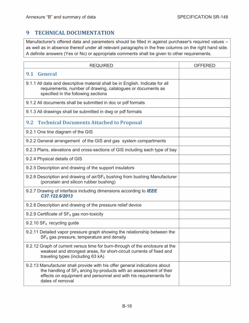
Manufacturer's offered data and parameters should be filled in against purchaser's required values –
as well as in absence thereof under all relevant paragraphs in the free columns on the right hand side.
A definite answers (Yes or No) or appropriate comments shall be given to other requirements.
REQUIRED OFFERED
9.1 General
All data and descriptive material shall be in English. Indicate for all 9.1.1requirements, number of drawing, catalogues or documents as specified in the following sections
All documents shall be submitted in doc or pdf formats 9.1.2
All drawings shall be submitted in dwg or pdf formats 9.1.3
9.2 Technical Documents Attached to Proposal
One line diagram of the GIS 9.2.1
General arrangement of the GIS and gas system compartments 9.2.2
Plans, elevations and cross-sections of GIS including each type of bay 9.2.3
Physical details of GIS 9.2.4
Description and drawing of the support insulators 9.2.5
Description and drawing of air/SF6 bushing from bushing Manufacturer 9.2.6(porcelain and silicon rubber bushing)
Drawing of interface including dimensions according to IEEE 9.2.7C37.122.6/2013
Description and drawing of the pressure relief device 9.2.8
Certificate of SF6 gas non-toxicity 9.2.9
SF6 recycling guide 9.2.10
Detailed vapor pressure graph showing the relationship between the 9.2.11SF6 gas pressure, temperature and density
Graph of current versus time for burn-through of the enclosure at the 9.2.12weakest and strongest areas, for short-circuit currents of fixed and traveling types (including 63 kA)
Manufacturer shall provide with his offer general indications about 9.2.13the handling of SF6 arcing by-products with an assessment of their effects on equipment and personnel and with his requirements for dates of removal
Annexure “B” and summary of data SPECIFICATION SR-148
B-19
REQUIRED OFFERED
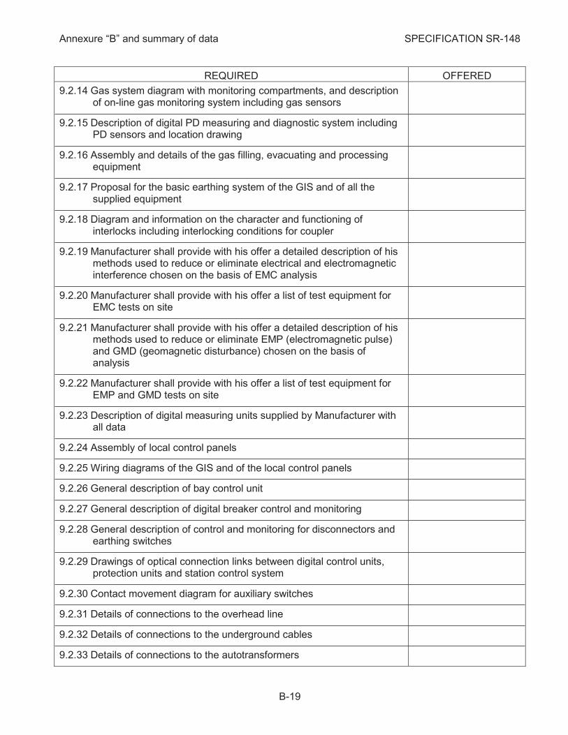
Gas system diagram with monitoring compartments, and description 9.2.14of on-line gas monitoring system including gas sensors
Description of digital PD measuring and diagnostic system including 9.2.15PD sensors and location drawing
Assembly and details of the gas filling, evacuating and processing 9.2.16equipment
Proposal for the basic earthing system of the GIS and of all the 9.2.17supplied equipment
Diagram and information on the character and functioning of 9.2.18interlocks including interlocking conditions for coupler
Manufacturer shall provide with his offer a detailed description of his 9.2.19methods used to reduce or eliminate electrical and electromagnetic interference chosen on the basis of EMC analysis
Manufacturer shall provide with his offer a list of test equipment for 9.2.20EMC tests on site
Manufacturer shall provide with his offer a detailed description of his 9.2.21methods used to reduce or eliminate EMP (electromagnetic pulse) and GMD (geomagnetic disturbance) chosen on the basis of analysis
Manufacturer shall provide with his offer a list of test equipment for 9.2.22EMP and GMD tests on site
Description of digital measuring units supplied by Manufacturer with 9.2.23all data
Assembly of local control panels 9.2.24
Wiring diagrams of the GIS and of the local control panels 9.2.25
General description of bay control unit 9.2.26
General description of digital breaker control and monitoring 9.2.27
General description of control and monitoring for disconnectors and 9.2.28earthing switches
Drawings of optical connection links between digital control units, 9.2.29protection units and station control system
Contact movement diagram for auxiliary switches 9.2.30
Details of connections to the overhead line 9.2.31
Details of connections to the underground cables 9.2.32
Details of connections to the autotransformers 9.2.33
Annexure “B” and summary of data SPECIFICATION SR-148
B-20
REQUIRED OFFERED
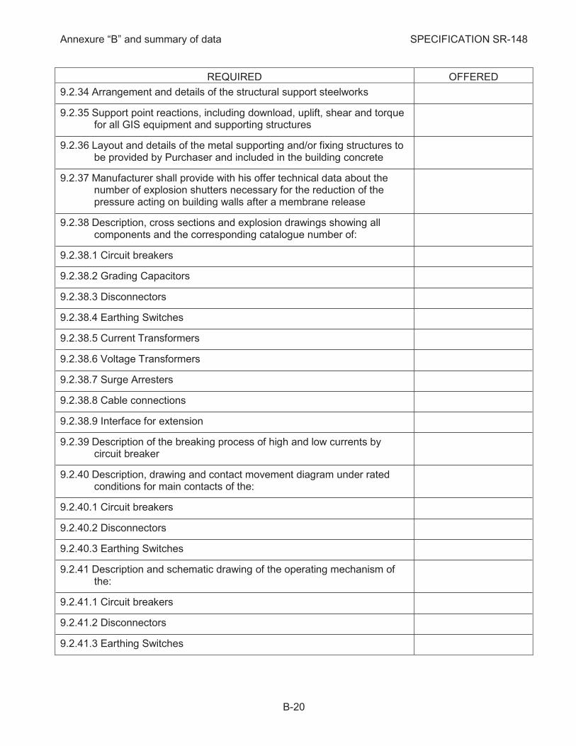
Arrangement and details of the structural support steelworks 9.2.34
Support point reactions, including download, uplift, shear and torque 9.2.35for all GIS equipment and supporting structures
Layout and details of the metal supporting and/or fixing structures to 9.2.36be provided by Purchaser and included in the building concrete
Manufacturer shall provide with his offer technical data about the 9.2.37number of explosion shutters necessary for the reduction of the pressure acting on building walls after a membrane release
Description, cross sections and explosion drawings showing all 9.2.38components and the corresponding catalogue number of:
9.2.38.1 Circuit breakers
9.2.38.2 Grading Capacitors
9.2.38.3 Disconnectors
9.2.38.4 Earthing Switches
9.2.38.5 Current Transformers
9.2.38.6 Voltage Transformers
9.2.38.7 Surge Arresters
9.2.38.8 Cable connections
9.2.38.9 Interface for extension
Description of the breaking process of high and low currents by 9.2.39circuit breaker
Description, drawing and contact movement diagram under rated 9.2.40conditions for main contacts of the:
9.2.40.1 Circuit breakers
9.2.40.2 Disconnectors
9.2.40.3 Earthing Switches
Description and schematic drawing of the operating mechanism of 9.2.41the:
9.2.41.1 Circuit breakers
9.2.41.2 Disconnectors
9.2.41.3 Earthing Switches
Annexure “B” and summary of data SPECIFICATION SR-148
B-21
REQUIRED OFFERED
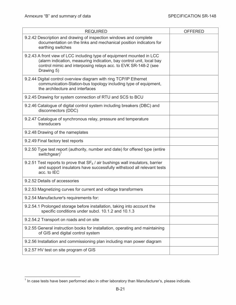
Description and drawing of inspection windows and complete 9.2.42documentation on the links and mechanical position indicators for earthing switches
A front view of LCC including type of equipment mounted in LCC 9.2.43(alarm indication, measuring indication, bay control unit, local bay control mimic and interposing relays acc. to EVK SR-148-2 (see Drawing 5)
Digital control overview diagram with ring TCP/IP Ethernet 9.2.44communication-Station-bus topology including type of equipment, the architecture and interfaces
Drawing for system connection of RTU and SCS to BCU 9.2.45
Catalogue of digital control system including breakers (DBC) and 9.2.46disconnectors (DDC)
Catalogue of synchronous relay, pressure and temperature 9.2.47transducers
Drawing of the nameplates 9.2.48
Final factory test reports 9.2.49
Type test report (authority, number and date) for offered type (entire 9.2.50switchgear)1
Test reports to prove that SF6 / air bushings wall insulators, barrier 9.2.51and support insulators have successfully withstood all relevant tests acc. to IEC
Details of accessories 9.2.52
Magnetizing curves for current and voltage transformers 9.2.53
Manufacturer's requirements for: 9.2.54
9.2.54.1 Prolonged storage before installation, taking into account the specific conditions under subcl. 10.1.2 and 10.1.3
9.2.54.2 Transport on roads and on site
General instruction books for installation, operating and maintaining 9.2.55of GIS and digital control system
Installation and commissioning plan including man power diagram 9.2.56
HV test on site program of GIS 9.2.57
1 In case tests have been performed also in other laboratory than Manufacturer’s, please indicate.
Annexure “B” and summary of data SPECIFICATION SR-148
B-22
REQUIRED OFFERED
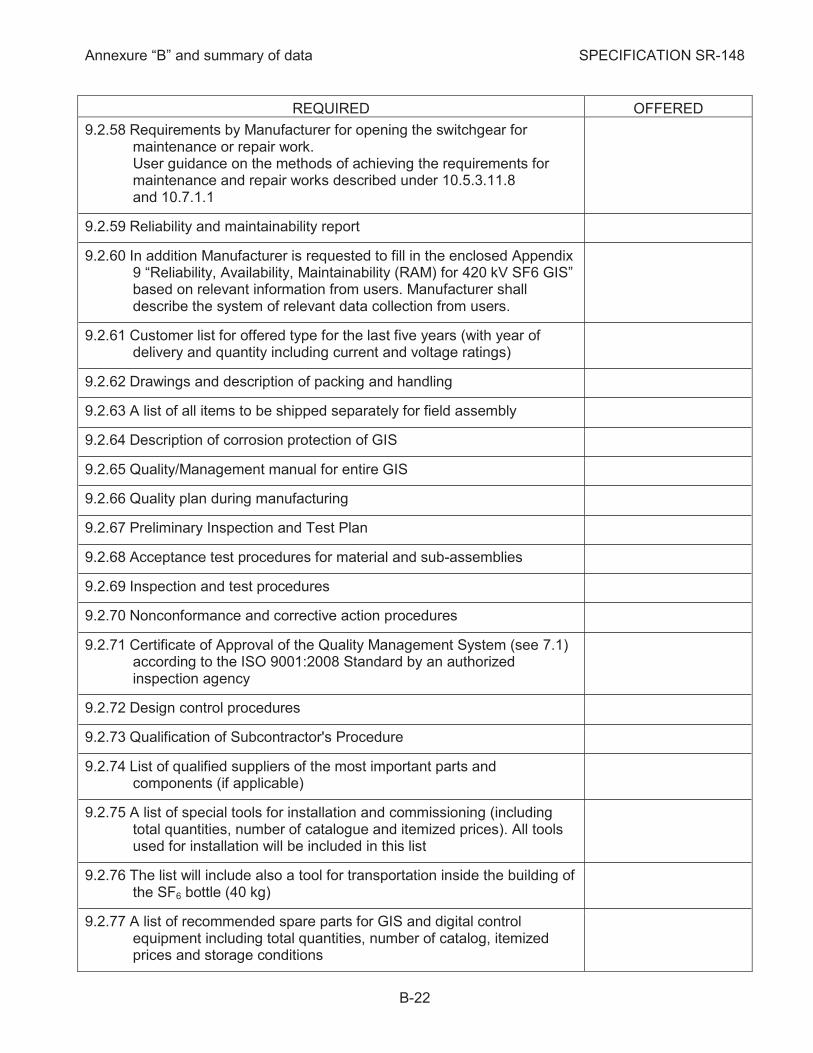
Requirements by Manufacturer for opening the switchgear for 9.2.58maintenance or repair work. User guidance on the methods of achieving the requirements for maintenance and repair works described under 10.5.3.11.8 and 10.7.1.1
Reliability and maintainability report 9.2.59
In addition Manufacturer is requested to fill in the enclosed Appendix 9.2.609 “Reliability, Availability, Maintainability (RAM) for 420 kV SF6 GIS” based on relevant information from users. Manufacturer shall describe the system of relevant data collection from users.
Customer list for offered type for the last five years (with year of 9.2.61delivery and quantity including current and voltage ratings)
Drawings and description of packing and handling 9.2.62
A list of all items to be shipped separately for field assembly 9.2.63
Description of corrosion protection of GIS 9.2.64
Quality/Management manual for entire GIS 9.2.65
Quality plan during manufacturing 9.2.66
Preliminary Inspection and Test Plan 9.2.67
Acceptance test procedures for material and sub-assemblies 9.2.68
Inspection and test procedures 9.2.69
Nonconformance and corrective action procedures 9.2.70
Certificate of Approval of the Quality Management System (see 7.1) 9.2.71according to the ISO 9001:2008 Standard by an authorized inspection agency
Design control procedures 9.2.72
Qualification of Subcontractor's Procedure 9.2.73
List of qualified suppliers of the most important parts and 9.2.74components (if applicable)
A list of special tools for installation and commissioning (including 9.2.75total quantities, number of catalogue and itemized prices). All tools used for installation will be included in this list
The list will include also a tool for transportation inside the building of 9.2.76the SF6 bottle (40 kg)
A list of recommended spare parts for GIS and digital control 9.2.77equipment including total quantities, number of catalog, itemized prices and storage conditions
Annexure “B” and summary of data SPECIFICATION SR-148
B-23
REQUIRED OFFERED
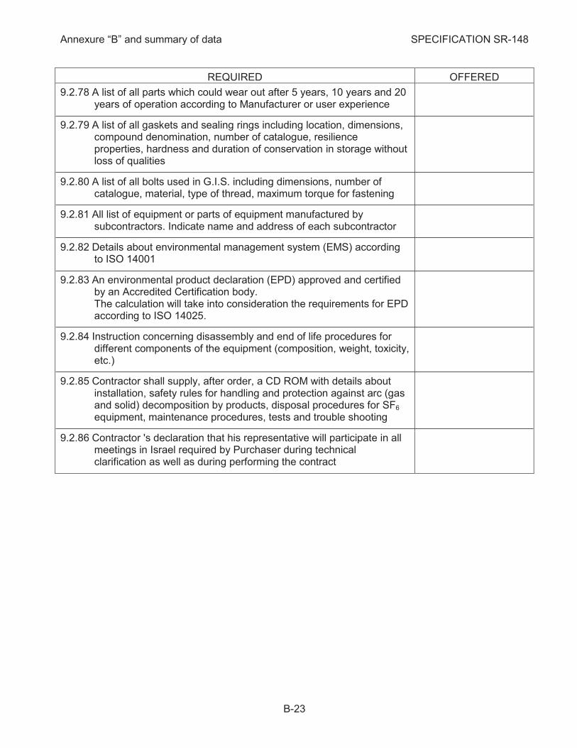
A list of all parts which could wear out after 5 years, 10 years and 20 9.2.78years of operation according to Manufacturer or user experience
A list of all gaskets and sealing rings including location, dimensions, 9.2.79compound denomination, number of catalogue, resilience properties, hardness and duration of conservation in storage without loss of qualities
A list of all bolts used in G.I.S. including dimensions, number of 9.2.80catalogue, material, type of thread, maximum torque for fastening
All list of equipment or parts of equipment manufactured by 9.2.81subcontractors. Indicate name and address of each subcontractor
Details about environmental management system (EMS) according 9.2.82to ISO 14001
An environmental product declaration (EPD) approved and certified 9.2.83by an Accredited Certification body. The calculation will take into consideration the requirements for EPD according to ISO 14025.
Instruction concerning disassembly and end of life procedures for 9.2.84different components of the equipment (composition, weight, toxicity, etc.)
Contractor shall supply, after order, a CD ROM with details about 9.2.85installation, safety rules for handling and protection against arc (gas and solid) decomposition by products, disposal procedures for SF6 equipment, maintenance procedures, tests and trouble shooting
Contractor 's declaration that his representative will participate in all 9.2.86meetings in Israel required by Purchaser during technical clarification as well as during performing the contract
Annexure “B” and summary of data SPECIFICATION SR-148
B-24
REQUIRED OFFERED
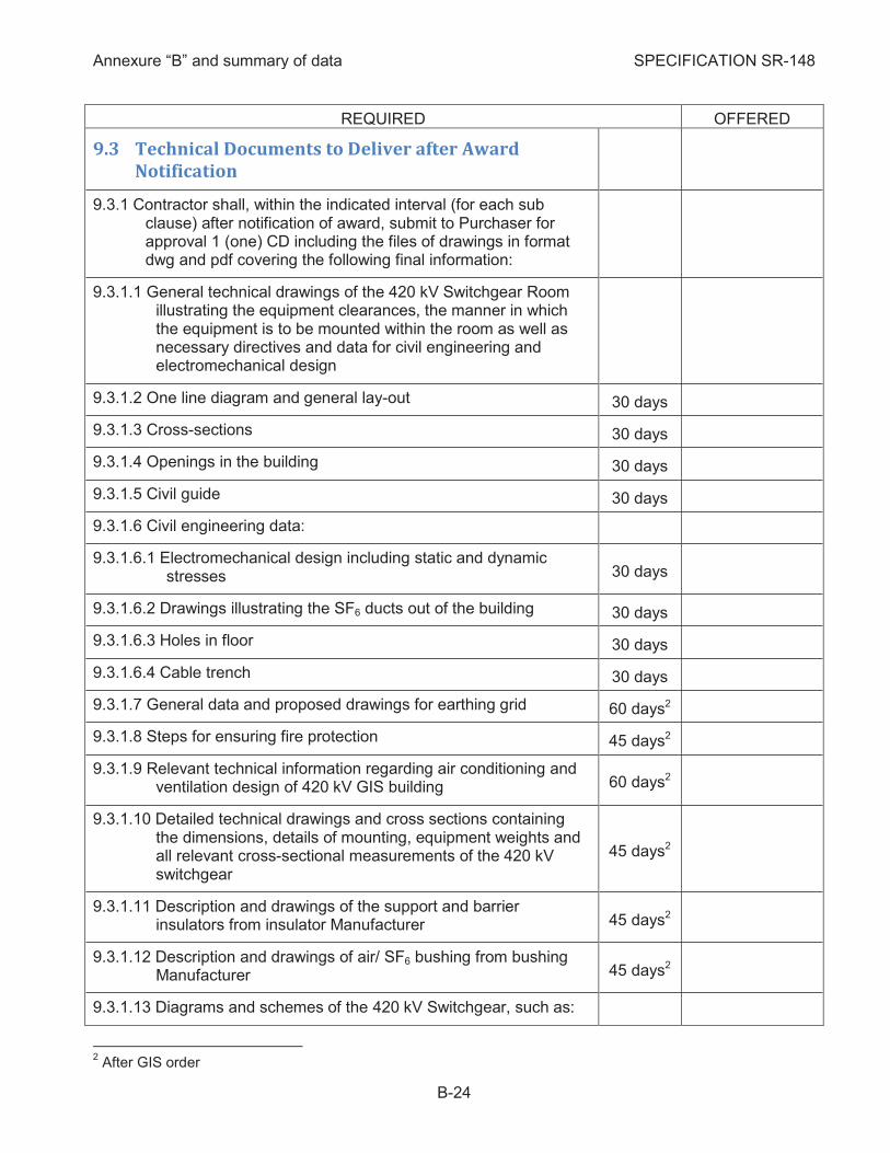
9.3 Technical Documents to Deliver after Award
Notification
Contractor shall, within the indicated interval (for each sub 9.3.1clause) after notification of award, submit to Purchaser for approval 1 (one) CD including the files of drawings in format dwg and pdf covering the following final information:
9.3.1.1 General technical drawings of the 420 kV Switchgear Room illustrating the equipment clearances, the manner in which the equipment is to be mounted within the room as well as necessary directives and data for civil engineering and electromechanical design
9.3.1.2 One line diagram and general lay-out 30 days
9.3.1.3 Cross-sections 30 days
9.3.1.4 Openings in the building 30 days
9.3.1.5 Civil guide 30 days
9.3.1.6 Civil engineering data:
9.3.1.6.1 Electromechanical design including static and dynamic stresses 30 days
9.3.1.6.2 Drawings illustrating the SF6 ducts out of the building 30 days
9.3.1.6.3 Holes in floor 30 days
9.3.1.6.4 Cable trench 30 days
9.3.1.7 General data and proposed drawings for earthing grid 60 days2
9.3.1.8 Steps for ensuring fire protection 45 days2
9.3.1.9 Relevant technical information regarding air conditioning and ventilation design of 420 kV GIS building 60 days2
9.3.1.10 Detailed technical drawings and cross sections containing the dimensions, details of mounting, equipment weights and all relevant cross-sectional measurements of the 420 kV switchgear
45 days2
9.3.1.11 Description and drawings of the support and barrier insulators from insulator Manufacturer 45 days2
9.3.1.12 Description and drawings of air/ SF6 bushing from bushing Manufacturer 45 days2
9.3.1.13 Diagrams and schemes of the 420 kV Switchgear, such as:
2 After GIS order
Annexure “B” and summary of data SPECIFICATION SR-148
B-25
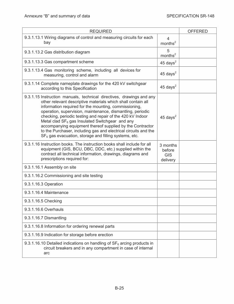
REQUIRED OFFERED
9.3.1.13.1 Wiring diagrams of control and measuring circuits for each bay
4 months2
9.3.1.13.2 Gas distribution diagram 5 months2
9.3.1.13.3 Gas compartment scheme 45 days2
9.3.1.13.4 Gas monitoring scheme, including all devices for measuring, control and alarm 45 days2
9.3.1.14 Complete nameplate drawings for the 420 kV switchgear according to this Specification 45 days2
9.3.1.15 Instruction manuals, technical directives, drawings and any other relevant descriptive materials which shall contain all information required for the mounting, commissioning, operation, supervision, maintenance, dismantling, periodic checking, periodic testing and repair of the 420 kV Indoor Metal clad SF6 gas Insulated Switchgear and any accompanying equipment thereof supplied by the Contractor to the Purchaser, including gas and electrical circuits and the SF6 gas evacuation, storage and filling systems, etc.
45 days2
9.3.1.16 Instruction books. The instruction books shall include for all equipment (GIS, BCU, DBC, DDC, etc.) supplied within the contract all technical information, drawings, diagrams and prescriptions required for:
3 months before GIS
delivery
9.3.1.16.1 Assembly on site
9.3.1.16.2 Commissioning and site testing
9.3.1.16.3 Operation
9.3.1.16.4 Maintenance
9.3.1.16.5 Checking
9.3.1.16.6 Overhauls
9.3.1.16.7 Dismantling
9.3.1.16.8 Information for ordering renewal parts
9.3.1.16.9 Indication for storage before erection
9.3.1.16.10 Detailed indications on handling of SF6 arcing products in circuit breakers and in any compartment in case of internal arc
Annexure “B” and summary of data SPECIFICATION SR-148
B-26
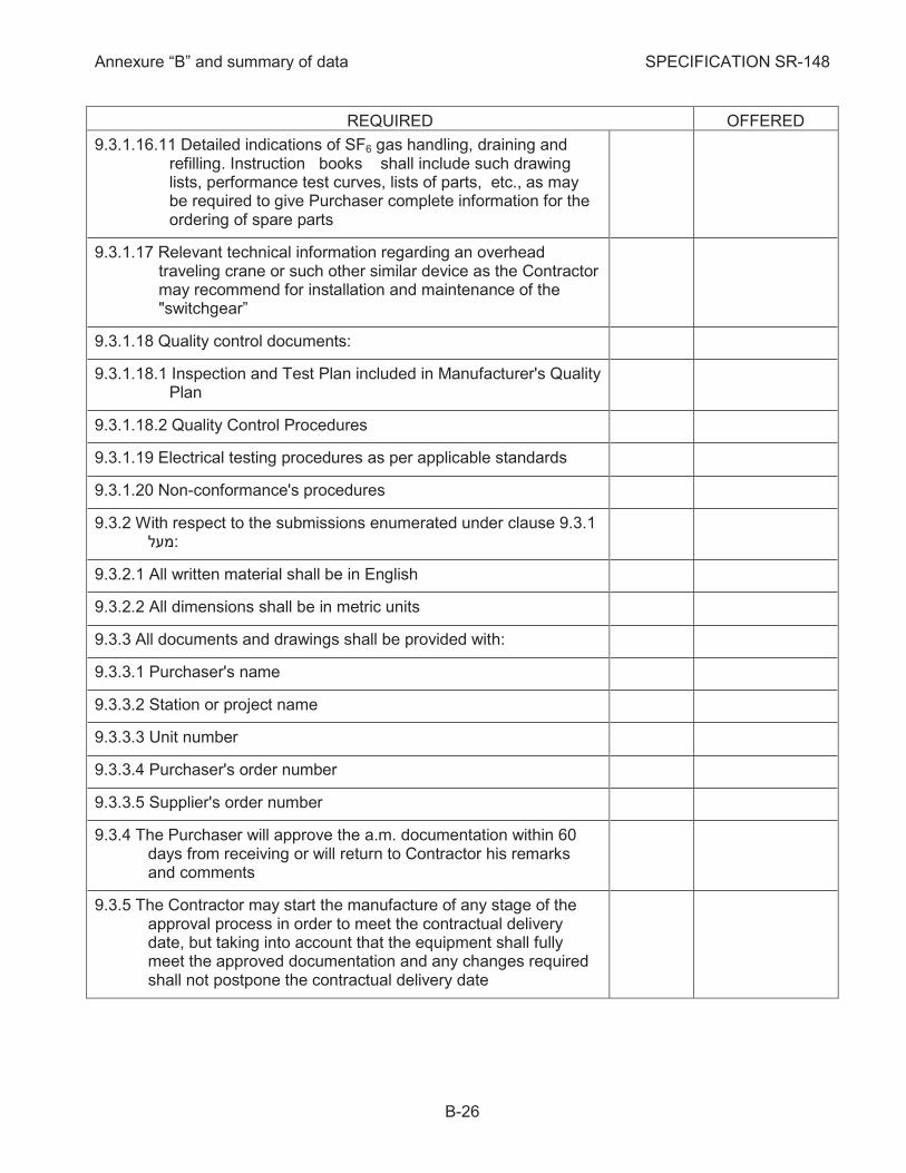
REQUIRED OFFERED
9.3.1.16.11 Detailed indications of SF6 gas handling, draining and refilling. Instruction books shall include such drawing lists, performance test curves, lists of parts, etc., as may be required to give Purchaser complete information for the ordering of spare parts
9.3.1.17 Relevant technical information regarding an overhead traveling crane or such other similar device as the Contractor may recommend for installation and maintenance of the "switchgear”
9.3.1.18 Quality control documents:
9.3.1.18.1 Inspection and Test Plan included in Manufacturer's Quality Plan
9.3.1.18.2 Quality Control Procedures
9.3.1.19 Electrical testing procedures as per applicable standards
9.3.1.20 Non-conformance's procedures
With respect to the submissions enumerated under clause 9.3.1 9.3.2 :מעל
9.3.2.1 All written material shall be in English
9.3.2.2 All dimensions shall be in metric units
All documents and drawings shall be provided with: 9.3.3
9.3.3.1 Purchaser's name
9.3.3.2 Station or project name
9.3.3.3 Unit number
9.3.3.4 Purchaser's order number
9.3.3.5 Supplier's order number
The Purchaser will approve the a.m. documentation within 60 9.3.4days from receiving or will return to Contractor his remarks and comments
The Contractor may start the manufacture of any stage of the 9.3.5approval process in order to meet the contractual delivery date, but taking into account that the equipment shall fully meet the approved documentation and any changes required shall not postpone the contractual delivery date

Annexure “B” and summary of data SPECIFICATION SR-148
B-27
REQUIRED OFFERED
If all, or any part, of the submissions indicated under 9.3.1 9.3.6 מעלare returned by Purchaser, stamped "Approved Except as Noted", Contractor shall correct the drawings in accordance with the Purchaser's markings and shall resubmit the corrected submissions within 30 days from the receiving date of Purchaser's remarks with the files of drawings in format DWG as finally approved by Purchaser. This process will be continued until of approval of all a.m. documentation.
In addition to the drawing requirements, Contractor shall furnish 9.3.7a comprehensive outline as to the extent of field fabrication required, cleaning, checking, inspection, painting, testing, etc., to be done by the Erector
Contractor shall complete engineering details immediately after 9.3.8award of contract, regardless of shipping date
After approval of the drawings and instruction books the 9.3.9Contractor shall submit to the Purchaser the following:
9.3.9.1 Two (2) sets of prints of all drawings and one (1) CD with the files of drawings in PDF and DWG format
9.3.9.2 Two (2) sets of complete instruction books and one (1) CD
9.3.9.3 Mounting drawing in two (2) copies and one (1) CD including detailed list with each Item, technological sequence for erection and erection time table
2 months before GIS
delivery
9.3.9.4 Routine test reports for approval by Purchaser in one (1) CD 1 month before GIS
delivery
9.3.9.5 Installation and Erection Commissioning program for approval by Purchaser in one (1) CD
3 months before GIS
delivery
Annexure “B” and summary of data SPECIFICATION SR-148
B-28
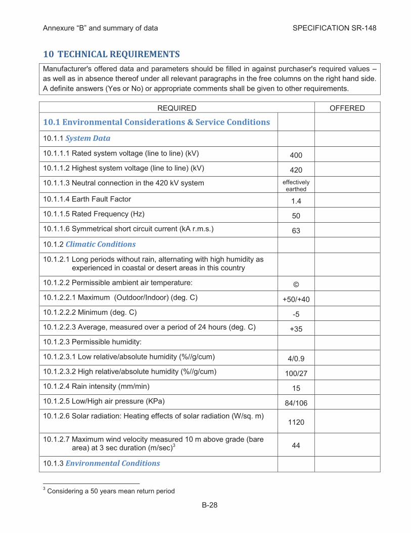
10 TECHNICAL REQUIREMENTS
Manufacturer's offered data and parameters should be filled in against purchaser's required values –
as well as in absence thereof under all relevant paragraphs in the free columns on the right hand side.
A definite answers (Yes or No) or appropriate comments shall be given to other requirements.
REQUIRED OFFERED
10.1 Environmental Considerations & Service Conditions
System Data 10.1.1
10.1.1.1 Rated system voltage (line to line) (kV) 400
10.1.1.2 Highest system voltage (line to line) (kV) 420
10.1.1.3 Neutral connection in the 420 kV system effectively earthed
10.1.1.4 Earth Fault Factor 1.4
10.1.1.5 Rated Frequency (Hz) 50
10.1.1.6 Symmetrical short circuit current (kA r.m.s.) 63
Climatic Conditions 10.1.2
10.1.2.1 Long periods without rain, alternating with high humidity as experienced in coastal or desert areas in this country
10.1.2.2 Permissible ambient air temperature: ©
10.1.2.2.1 Maximum (Outdoor/Indoor) (deg. C) +50/+40
10.1.2.2.2 Minimum (deg. C) -5
10.1.2.2.3 Average, measured over a period of 24 hours (deg. C) +35
10.1.2.3 Permissible humidity:
10.1.2.3.1 Low relative/absolute humidity (%//g/cum) 4/0.9
10.1.2.3.2 High relative/absolute humidity (%//g/cum) 100/27
10.1.2.4 Rain intensity (mm/min) 15
10.1.2.5 Low/High air pressure (KPa) 84/106
10.1.2.6 Solar radiation: Heating effects of solar radiation (W/sq. m) 1120
10.1.2.7 Maximum wind velocity measured 10 m above grade (bare area) at 3 sec duration (m/sec)3 44
Environmental Conditions 10.1.3
3 Considering a 50 years mean return period
Annexure “B” and summary of data SPECIFICATION SR-148
B-29
REQUIRED OFFERED
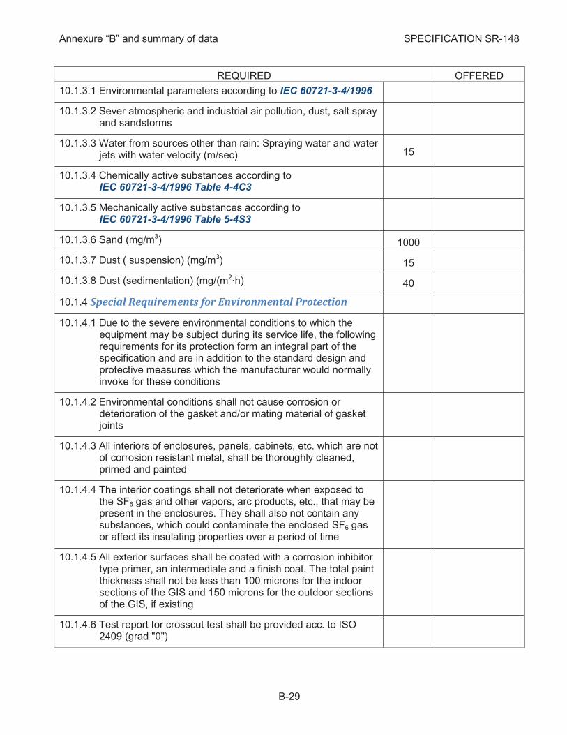
10.1.3.1 Environmental parameters according to IEC 60721-3-4/1996
10.1.3.2 Sever atmospheric and industrial air pollution, dust, salt spray and sandstorms
10.1.3.3 Water from sources other than rain: Spraying water and water jets with water velocity (m/sec) 15
10.1.3.4 Chemically active substances according to IEC 60721-3-4/1996 Table 4-4C3
10.1.3.5 Mechanically active substances according to IEC 60721-3-4/1996 Table 5-4S3
10.1.3.6 Sand (mg/m3) 1000
10.1.3.7 Dust ( suspension) (mg/m3) 15
10.1.3.8 Dust (sedimentation) (mg/(m2∙h) 40
Special Requirements for Environmental Protection 10.1.4
10.1.4.1 Due to the severe environmental conditions to which the equipment may be subject during its service life, the following requirements for its protection form an integral part of the specification and are in addition to the standard design and protective measures which the manufacturer would normally invoke for these conditions
10.1.4.2 Environmental conditions shall not cause corrosion or deterioration of the gasket and/or mating material of gasket joints
10.1.4.3 All interiors of enclosures, panels, cabinets, etc. which are not of corrosion resistant metal, shall be thoroughly cleaned, primed and painted
10.1.4.4 The interior coatings shall not deteriorate when exposed to the SF6 gas and other vapors, arc products, etc., that may be present in the enclosures. They shall also not contain any substances, which could contaminate the enclosed SF6 gas or affect its insulating properties over a period of time
10.1.4.5 All exterior surfaces shall be coated with a corrosion inhibitor type primer, an intermediate and a finish coat. The total paint thickness shall not be less than 100 microns for the indoor sections of the GIS and 150 microns for the outdoor sections of the GIS, if existing
10.1.4.6 Test report for crosscut test shall be provided acc. to ISO 2409 (grad "0")
Annexure “B” and summary of data SPECIFICATION SR-148
B-30
REQUIRED OFFERED
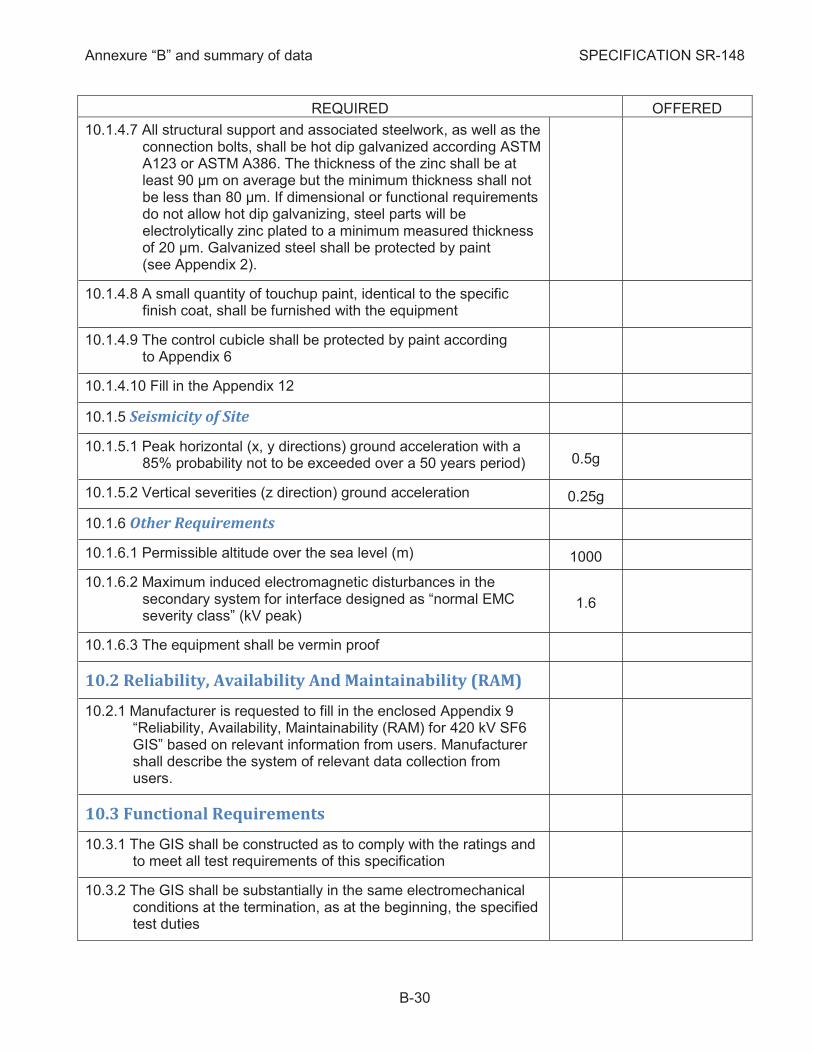
10.1.4.7 All structural support and associated steelwork, as well as the connection bolts, shall be hot dip galvanized according ASTM A123 or ASTM A386. The thickness of the zinc shall be at least 90 μm on average but the minimum thickness shall not be less than 80 μm. If dimensional or functional requirements do not allow hot dip galvanizing, steel parts will be electrolytically zinc plated to a minimum measured thickness of 20 μm. Galvanized steel shall be protected by paint (see Appendix 2).
10.1.4.8 A small quantity of touchup paint, identical to the specific finish coat, shall be furnished with the equipment
10.1.4.9 The control cubicle shall be protected by paint according to Appendix 6
10.1.4.10 Fill in the Appendix 12
Seismicity of Site 10.1.5
10.1.5.1 Peak horizontal (x, y directions) ground acceleration with a 85% probability not to be exceeded over a 50 years period) 0.5g
10.1.5.2 Vertical severities (z direction) ground acceleration 0.25g
Other Requirements 10.1.6
10.1.6.1 Permissible altitude over the sea level (m) 1000
10.1.6.2 Maximum induced electromagnetic disturbances in the secondary system for interface designed as “normal EMC severity class” (kV peak)
1.6
10.1.6.3 The equipment shall be vermin proof
10.2 Reliability, Availability And Maintainability (RAM)
Manufacturer is requested to fill in the enclosed Appendix 9 10.2.1“Reliability, Availability, Maintainability (RAM) for 420 kV SF6 GIS” based on relevant information from users. Manufacturer shall describe the system of relevant data collection from users.
10.3 Functional Requirements
The GIS shall be constructed as to comply with the ratings and 10.3.1to meet all test requirements of this specification
The GIS shall be substantially in the same electromechanical 10.3.2conditions at the termination, as at the beginning, the specified test duties

Annexure “B” and summary of data SPECIFICATION SR-148
B-31
REQUIRED OFFERED
Accuracy requirements for CT's with tapped secondary 10.3.3windings shall refer to the highest and lowest ratios acc. to IEC 61869-2 cl.5.6.203.2
©
10.4 Properties
Electrical Data4 10.4.1 ©
10.4.1.1 Rated voltage Ur (kV) 420
10.4.1.2 Rated insulation level (at the minimum operating density of the equipment):
10.4.1.2.1 Lightning impulse withstand voltage
10.4.1.2.1.1 Phase to earth Up (kV peak) 1425
10.4.1.2.1.2 Across open switching device and isolating distance Up (kV peak)
1425 (+240)5
10.4.1.2.2 Switching impulse withstand voltage
10.4.1.2.2.1 Phase to earth and across open switching device (kV peak) 1050
10.4.1.2.2.2 Across isolating distance 900 (+345)6
10.4.1.2.3 Power frequency withstand voltage for 60 sec:
10.4.1.2.3.1 Phase to earth Ud (kV r.m.s.) 650
10.4.1.2.3.2 Across open switching device and isolating distance Ud (kV r.m.s) 815
10.4.1.3 Power frequency withstand of switchgear bays at
atmospheric pressure of SF6 gas and 20°C :
10.4.1.3.1 Power frequency withstand voltage for 60 sec:
10.4.1.3.1.1 Phase to earth (kV r.m.s.)
10.4.1.3.1.2 Across open switching device and isolating distance (kV r.m.s.)
10.4.1.3.2 Power frequency withstand voltage continuous:
10.4.1.3.2.1 Phase to earth (kV r.m.s.)
4 The terms used here are in general according to IEC recommendations. In case that Manufacturer can supply
GIS with higher performance than those acc. to IEC standards or IECo requirements, he should indicate his offered values and relevant standards, etc., which they conform. 5 Applied to the opposite terminal
6 Applied to the opposite terminal
Annexure “B” and summary of data SPECIFICATION SR-148
B-32
REQUIRED OFFERED
10.4.1.3.2.2 Across open switching device and isolating distance (kV r.m.s.)
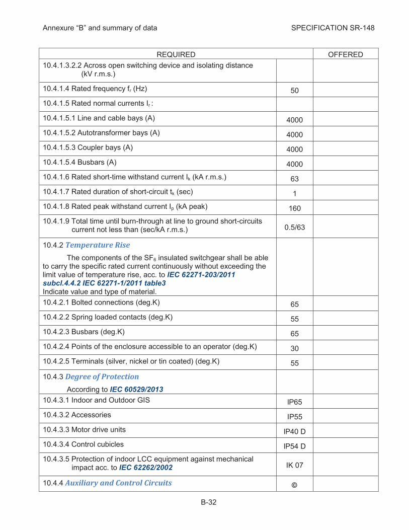
10.4.1.4 Rated frequency fr (Hz) 50
10.4.1.5 Rated normal currents Ir :
10.4.1.5.1 Line and cable bays (A) 4000
10.4.1.5.2 Autotransformer bays (A) 4000
10.4.1.5.3 Coupler bays (A) 4000
10.4.1.5.4 Busbars (A) 4000
10.4.1.6 Rated short-time withstand current Ik (kA r.m.s.) 63
10.4.1.7 Rated duration of short-circuit tk (sec) 1
10.4.1.8 Rated peak withstand current Ip (kA peak) 160
10.4.1.9 Total time until burn-through at line to ground short-circuits current not less than (sec/kA r.m.s.) 0.5/63
Temperature Rise 10.4.2
The components of the SF6 insulated switchgear shall be able to carry the specific rated current continuously without exceeding the limit value of temperature rise, acc. to IEC 62271-203/2011 subcl.4.4.2 IEC 62271-1/2011 table3 Indicate value and type of material.
10.4.2.1 Bolted connections (deg.K) 65
10.4.2.2 Spring loaded contacts (deg.K) 55
10.4.2.3 Busbars (deg.K) 65
10.4.2.4 Points of the enclosure accessible to an operator (deg.K) 30
10.4.2.5 Terminals (silver, nickel or tin coated) (deg.K) 55
Degree of Protection 10.4.3
According to IEC 60529/2013
10.4.3.1 Indoor and Outdoor GIS lP65
10.4.3.2 Accessories IP55
10.4.3.3 Motor drive units lP40 D
10.4.3.4 Control cubicles lP54 D
10.4.3.5 Protection of indoor LCC equipment against mechanical impact acc. to IEC 62262/2002 IK 07
Auxiliary and Control Circuits 10.4.4 ã
Annexure “B” and summary of data SPECIFICATION SR-148
B-33
REQUIRED OFFERED
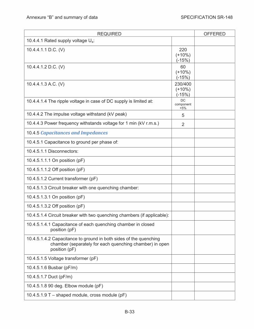
10.4.4.1 Rated supply voltage Ua:
10.4.4.1.1 D.C. (V) 220 (+10%) (-15%)
10.4.4.1.2 D.C. (V) 60 (+10%) (-15%)
10.4.4.1.3 A.C. (V) 230/400 (+10%) (-15%)
10.4.4.1.4 The ripple voltage in case of DC supply is limited at: DC component
+5%
10.4.4.2 The impulse voltage withstand (kV peak) 5
10.4.4.3 Power frequency withstands voltage for 1 min (kV r.m.s.) 2
Capacitances and Impedances 10.4.5
10.4.5.1 Capacitance to ground per phase of:
10.4.5.1.1 Disconnectors:
10.4.5.1.1.1 On position (pF)
10.4.5.1.1.2 Off position (pF)
10.4.5.1.2 Current transformer (pF)
10.4.5.1.3 Circuit breaker with one quenching chamber:
10.4.5.1.3.1 On position (pF)
10.4.5.1.3.2 Off position (pF)
10.4.5.1.4 Circuit breaker with two quenching chambers (if applicable):
10.4.5.1.4.1 Capacitance of each quenching chamber in closed position (pF)
10.4.5.1.4.2 Capacitance to ground in both sides of the quenching chamber (separately for each quenching chamber) in open position (pF)
10.4.5.1.5 Voltage transformer (pF)
10.4.5.1.6 Busbar (pF/m)
10.4.5.1.7 Duct (pF/m)
10.4.5.1.8 90 deg. Elbow module (pF)
10.4.5.1.9 T – shaped module, cross module (pF)

Annexure “B” and summary of data SPECIFICATION SR-148
B-34
REQUIRED OFFERED
10.4.5.1.10 Barrier insulator (pF)
10.4.5.1.11 Support insulator (pF)
10.4.5.1.12 SF-6 outdoor bushing (pF)
10.4.5.2 Capacitance to ground of:
10.4.5.2.1 Cable bay (pF)
10.4.5.2.2 Line bay without connections (pF)
10.4.5.2.3 Autotransformer bay (pF)
10.4.5.2.4 Transversal Coupler bay (pF)
10.4.5.2.5 Busbar Measuring and Earthing bay (pF)
10.4.5.2.6 Disconnecting bay (pF)
10.4.5.2.7 Three phase main busbar (pF/m)
10.4.5.2.8 Total capacitance to ground of GIS (pF):
10.4.5.2.8.1 First stage (bays 01 to 07 and 13) (pF)
10.4.5.2.8.2 Optional stage (bays 08 to 12) (pF)
10.4.5.3 Surge impedance (W)
10.4.5.4 Inductance for busduct (H/m)
10.4.5.5 Resistance of busbar enclosure at fr (W/m)
10.4.5.6 Resistance of busbar conductor at fr (W/m)
Total thermal losses at rated current for each type of bay 10.4.6including the control cubicles which have to be taken into account as parameter for GIS building ventilation design (kW)
Seismic qualification of GIS equipment (including LCC) 10.4.7according to IEEE 693 /2011 and IEC 62271-207/2012 and IEC 60068-3-3 and IEC 61463/2000
10.4.7.1 Qualification level acc. to IEEE 693/2011 or IEC 62271-207/2012 Moderate
10.5 Design and Construction
General 10.5.1
10.5.1.1 The switchgear shall be designed for indoor installation, except the outgoing ducts and associated steel works and outdoor bushings which shall be designed for outdoor installation
Annexure “B” and summary of data SPECIFICATION SR-148
B-35
REQUIRED OFFERED
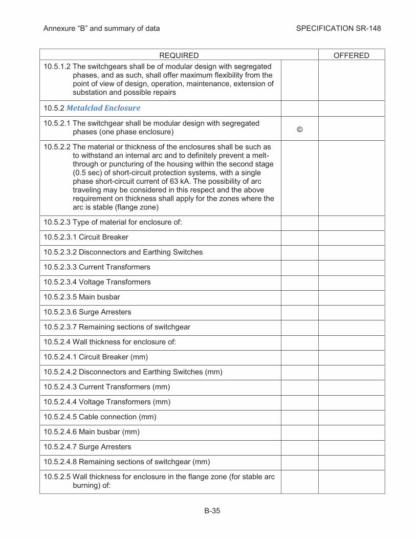
10.5.1.2 The switchgears shall be of modular design with segregated phases, and as such, shall offer maximum flexibility from the point of view of design, operation, maintenance, extension of substation and possible repairs
Metalclad Enclosure 10.5.2
10.5.2.1 The switchgear shall be modular design with segregated phases (one phase enclosure) ©
10.5.2.2 The material or thickness of the enclosures shall be such as to withstand an internal arc and to definitely prevent a melt-through or puncturing of the housing within the second stage (0.5 sec) of short-circuit protection systems, with a single phase short-circuit current of 63 kA. The possibility of arc traveling may be considered in this respect and the above requirement on thickness shall apply for the zones where the arc is stable (flange zone)
10.5.2.3 Type of material for enclosure of:
10.5.2.3.1 Circuit Breaker
10.5.2.3.2 Disconnectors and Earthing Switches
10.5.2.3.3 Current Transformers
10.5.2.3.4 Voltage Transformers
10.5.2.3.5 Main busbar
10.5.2.3.6 Surge Arresters
10.5.2.3.7 Remaining sections of switchgear
10.5.2.4 Wall thickness for enclosure of:
10.5.2.4.1 Circuit Breaker (mm)
10.5.2.4.2 Disconnectors and Earthing Switches (mm)
10.5.2.4.3 Current Transformers (mm)
10.5.2.4.4 Voltage Transformers (mm)
10.5.2.4.5 Cable connection (mm)
10.5.2.4.6 Main busbar (mm)
10.5.2.4.7 Surge Arresters
10.5.2.4.8 Remaining sections of switchgear (mm)
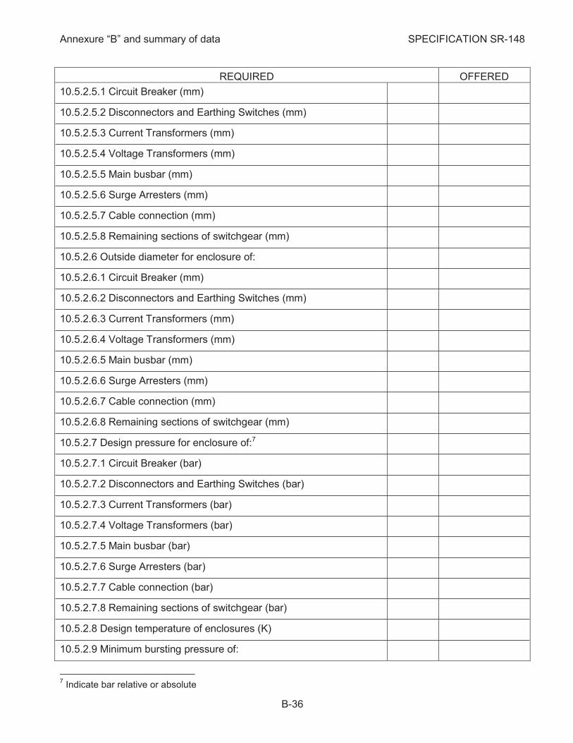
10.5.2.5 Wall thickness for enclosure in the flange zone (for stable arc burning) of:
Annexure “B” and summary of data SPECIFICATION SR-148
B-36
REQUIRED OFFERED
10.5.2.5.1 Circuit Breaker (mm)
10.5.2.5.2 Disconnectors and Earthing Switches (mm)
10.5.2.5.3 Current Transformers (mm)
10.5.2.5.4 Voltage Transformers (mm)
10.5.2.5.5 Main busbar (mm)
10.5.2.5.6 Surge Arresters (mm)
10.5.2.5.7 Cable connection (mm)
10.5.2.5.8 Remaining sections of switchgear (mm)
10.5.2.6 Outside diameter for enclosure of:
10.5.2.6.1 Circuit Breaker (mm)
10.5.2.6.2 Disconnectors and Earthing Switches (mm)
10.5.2.6.3 Current Transformers (mm)
10.5.2.6.4 Voltage Transformers (mm)
10.5.2.6.5 Main busbar (mm)
10.5.2.6.6 Surge Arresters (mm)
10.5.2.6.7 Cable connection (mm)
10.5.2.6.8 Remaining sections of switchgear (mm)
10.5.2.7 Design pressure for enclosure of:7
10.5.2.7.1 Circuit Breaker (bar)
10.5.2.7.2 Disconnectors and Earthing Switches (bar)
10.5.2.7.3 Current Transformers (bar)
10.5.2.7.4 Voltage Transformers (bar)
10.5.2.7.5 Main busbar (bar)
10.5.2.7.6 Surge Arresters (bar)
10.5.2.7.7 Cable connection (bar)
10.5.2.7.8 Remaining sections of switchgear (bar)
10.5.2.8 Design temperature of enclosures (K)
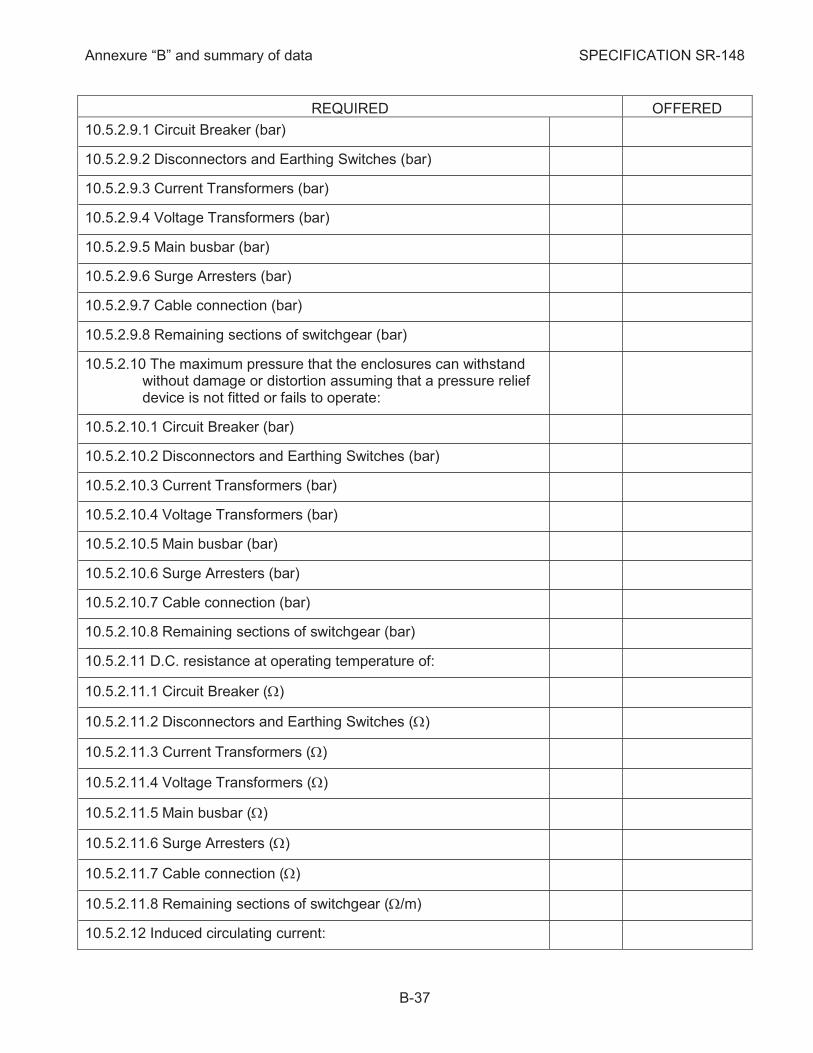
10.5.2.9 Minimum bursting pressure of:
7 Indicate bar relative or absolute
Annexure “B” and summary of data SPECIFICATION SR-148
B-37
REQUIRED OFFERED
10.5.2.9.1 Circuit Breaker (bar)
10.5.2.9.2 Disconnectors and Earthing Switches (bar)
10.5.2.9.3 Current Transformers (bar)
10.5.2.9.4 Voltage Transformers (bar)
10.5.2.9.5 Main busbar (bar)
10.5.2.9.6 Surge Arresters (bar)
10.5.2.9.7 Cable connection (bar)
10.5.2.9.8 Remaining sections of switchgear (bar)
10.5.2.10 The maximum pressure that the enclosures can withstand without damage or distortion assuming that a pressure relief device is not fitted or fails to operate:
10.5.2.10.1 Circuit Breaker (bar)
10.5.2.10.2 Disconnectors and Earthing Switches (bar)
10.5.2.10.3 Current Transformers (bar)
10.5.2.10.4 Voltage Transformers (bar)
10.5.2.10.5 Main busbar (bar)
10.5.2.10.6 Surge Arresters (bar)
10.5.2.10.7 Cable connection (bar)
10.5.2.10.8 Remaining sections of switchgear (bar)
10.5.2.11 D.C. resistance at operating temperature of:
10.5.2.11.1 Circuit Breaker (W)
10.5.2.11.2 Disconnectors and Earthing Switches (W)
10.5.2.11.3 Current Transformers (W)
10.5.2.11.4 Voltage Transformers (W)
10.5.2.11.5 Main busbar (W)
10.5.2.11.6 Surge Arresters (W)
10.5.2.11.7 Cable connection (W)
10.5.2.11.8 Remaining sections of switchgear (W/m)
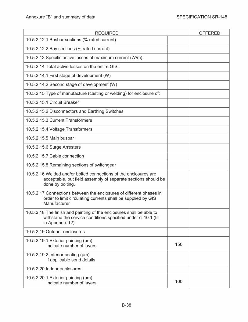
10.5.2.12 Induced circulating current:
Annexure “B” and summary of data SPECIFICATION SR-148
B-38
REQUIRED OFFERED
10.5.2.12.1 Busbar sections (% rated current)
10.5.2.12.2 Bay sections (% rated current)
10.5.2.13 Specific active losses at maximum current (W/m)
10.5.2.14 Total active losses on the entire GIS:
10.5.2.14.1 First stage of development (W)
10.5.2.14.2 Second stage of development (W)
10.5.2.15 Type of manufacture (casting or welding) for enclosure of:
10.5.2.15.1 Circuit Breaker
10.5.2.15.2 Disconnectors and Earthing Switches
10.5.2.15.3 Current Transformers
10.5.2.15.4 Voltage Transformers
10.5.2.15.5 Main busbar
10.5.2.15.6 Surge Arresters
10.5.2.15.7 Cable connection
10.5.2.15.8 Remaining sections of switchgear
10.5.2.16 Welded and/or bolted connections of the enclosures are acceptable, but field assembly of separate sections should be done by bolting.
10.5.2.17 Connections between the enclosures of different phases in order to limit circulating currents shall be supplied by GIS Manufacturer
10.5.2.18 The finish and painting of the enclosures shall be able to withstand the service conditions specified under cl. 10.1 (fill in Appendix 12)
10.5.2.19 Outdoor enclosures
10.5.2.19.1 Exterior painting (µm) Indicate number of layers 150
10.5.2.19.2 Interior coating (µm) If applicable send details
10.5.2.20 Indoor enclosures
10.5.2.20.1 Exterior painting (µm) Indicate number of layers 100
Annexure “B” and summary of data SPECIFICATION SR-148
B-39
REQUIRED OFFERED
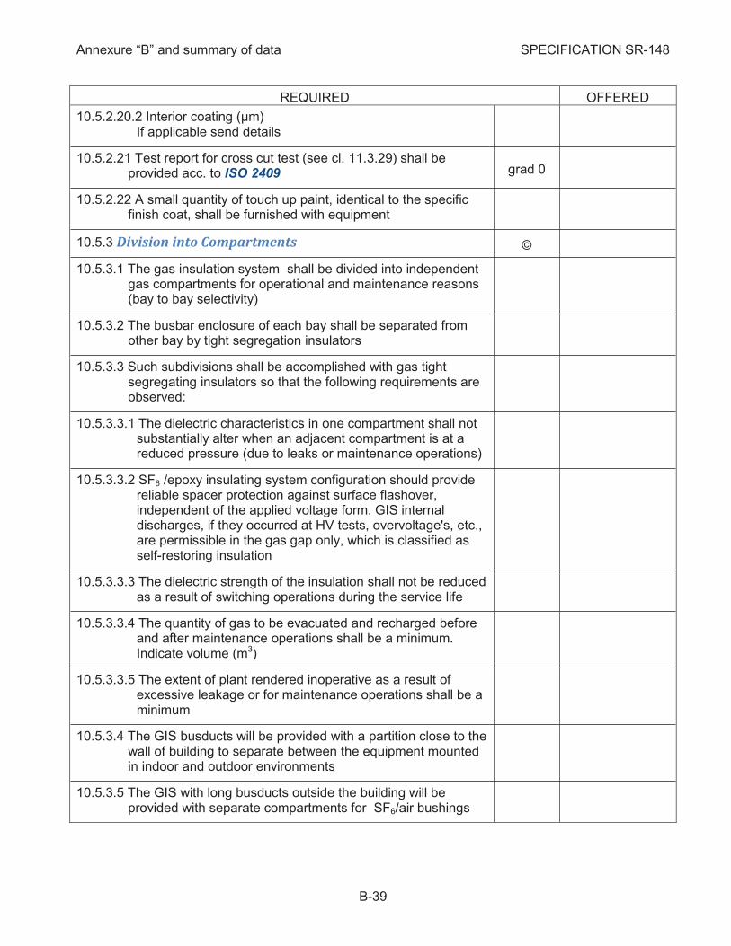
10.5.2.20.2 Interior coating (µm) If applicable send details
10.5.2.21 Test report for cross cut test (see cl. 11.3.29) shall be provided acc. to ISO 2409 grad 0
10.5.2.22 A small quantity of touch up paint, identical to the specific finish coat, shall be furnished with equipment
Division into Compartments 10.5.3 ©
10.5.3.1 The gas insulation system shall be divided into independent gas compartments for operational and maintenance reasons (bay to bay selectivity)
10.5.3.2 The busbar enclosure of each bay shall be separated from other bay by tight segregation insulators
10.5.3.3 Such subdivisions shall be accomplished with gas tight segregating insulators so that the following requirements are observed:
10.5.3.3.1 The dielectric characteristics in one compartment shall not substantially alter when an adjacent compartment is at a reduced pressure (due to leaks or maintenance operations)
10.5.3.3.2 SF6 /epoxy insulating system configuration should provide reliable spacer protection against surface flashover, independent of the applied voltage form. GIS internal discharges, if they occurred at HV tests, overvoltage's, etc., are permissible in the gas gap only, which is classified as self-restoring insulation
10.5.3.3.3 The dielectric strength of the insulation shall not be reduced as a result of switching operations during the service life
10.5.3.3.4 The quantity of gas to be evacuated and recharged before and after maintenance operations shall be a minimum. Indicate volume (m3)
10.5.3.3.5 The extent of plant rendered inoperative as a result of excessive leakage or for maintenance operations shall be a minimum
10.5.3.4 The GIS busducts will be provided with a partition close to the wall of building to separate between the equipment mounted in indoor and outdoor environments
10.5.3.5 The GIS with long busducts outside the building will be provided with separate compartments for SF6/air bushings
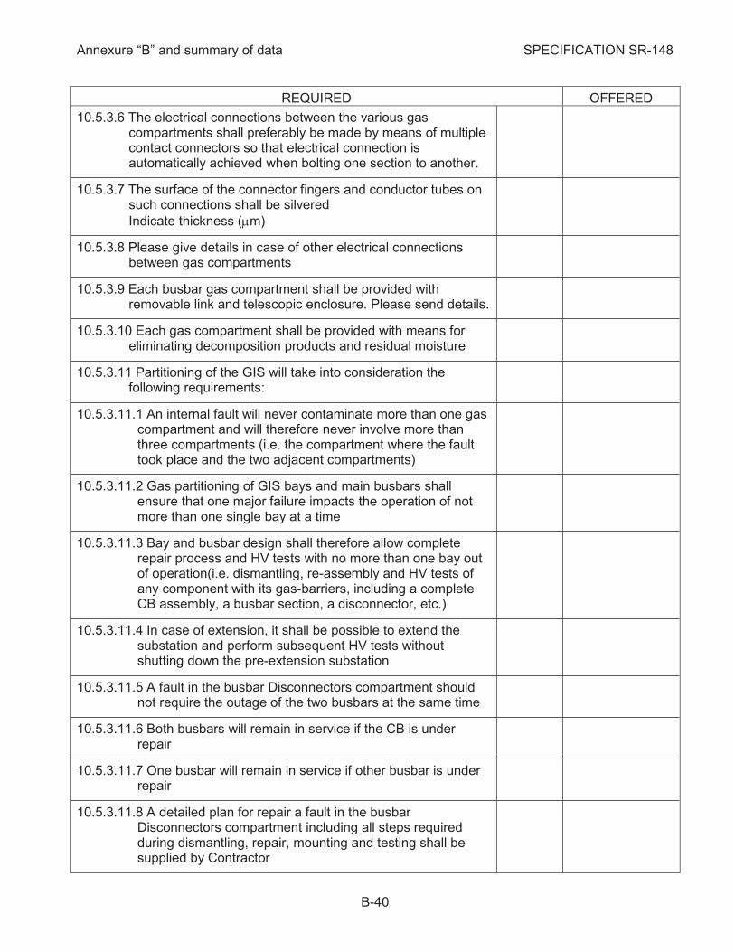
Annexure “B” and summary of data SPECIFICATION SR-148
B-40
REQUIRED OFFERED
10.5.3.6 The electrical connections between the various gas compartments shall preferably be made by means of multiple contact connectors so that electrical connection is automatically achieved when bolting one section to another.
10.5.3.7 The surface of the connector fingers and conductor tubes on such connections shall be silvered
Indicate thickness (mm)
10.5.3.8 Please give details in case of other electrical connections between gas compartments
10.5.3.9 Each busbar gas compartment shall be provided with removable link and telescopic enclosure. Please send details.
10.5.3.10 Each gas compartment shall be provided with means for eliminating decomposition products and residual moisture
10.5.3.11 Partitioning of the GIS will take into consideration the following requirements:
10.5.3.11.1 An internal fault will never contaminate more than one gas compartment and will therefore never involve more than three compartments (i.e. the compartment where the fault took place and the two adjacent compartments)
10.5.3.11.2 Gas partitioning of GIS bays and main busbars shall ensure that one major failure impacts the operation of not more than one single bay at a time
10.5.3.11.3 Bay and busbar design shall therefore allow complete repair process and HV tests with no more than one bay out of operation(i.e. dismantling, re-assembly and HV tests of any component with its gas-barriers, including a complete CB assembly, a busbar section, a disconnector, etc.)
10.5.3.11.4 In case of extension, it shall be possible to extend the substation and perform subsequent HV tests without shutting down the pre-extension substation
10.5.3.11.5 A fault in the busbar Disconnectors compartment should not require the outage of the two busbars at the same time
10.5.3.11.6 Both busbars will remain in service if the CB is under repair
10.5.3.11.7 One busbar will remain in service if other busbar is under repair
10.5.3.11.8 A detailed plan for repair a fault in the busbar Disconnectors compartment including all steps required during dismantling, repair, mounting and testing shall be supplied by Contractor

Annexure “B” and summary of data SPECIFICATION SR-148
B-41
REQUIRED OFFERED
10.5.3.11.9 The Contractor shall ensure all the components of the GIS offered type for a period of 15 (fifteen) years from the delivery of GIS. acc. to the contract
10.5.3.11.10 The Purchaser shall be informed by Contractor about the intention to change the offered type of GIS 2 (two) years before production interruption
Extension of GIS and connections to existing GIS 10.5.4
10.5.4.1 The 420kV GIS manufacturer should provide technical details of an interface compartment, for future extension, by a second manufacturer, with a simple bolted contact in according to IEEE C37.122.6 subcl. 7 Table A1 and Figures A.1&A.2
ã
10.5.4.1.1 Internal diameter of interface enclosure (mm)
10.5.4.1.2 External diameter of interface enclosure (mm)
10.5.4.1.3 Diameter of holes for bolting new interface bolts (mm)
10.5.4.1.4 Diameter of flat part of the contact support (mm)
10.5.4.1.5 Distance between flat end of contact support and flange
10.5.4.1.6 End of interface enclosure (mm)
10.5.4.1.7 Length of holes for bolting new contact bolts (mm)
10.5.4.1.8 Number and type of tapped holes for bolting the new conductor to contact support
10.5.4.1.9 Number of holes for bolting the interface cover/new enclosure
10.5.4.1.10 Flange bolt circle diameter of new interface bolts (mm)
10.5.4.1.11 Conductor bolt circle diameter for new contact bolts (mm)
10.5.4.1.12 SF6 pressure in zone II:
10.5.4.1.12.1 Rated filling pressure (kPa/psig)
10.5.4.1.12.2 Alarm pressure (kPa/psig)
10.5.4.1.12.3 Minimum functional pressure (kPa/psig)
10.5.4.1.13 Maximum permissible differential pressure of partition:
10.5.4.1.13.1 Continuously (kPa/psig)
10.5.4.1.13.2 During extension work (kPa/psig)
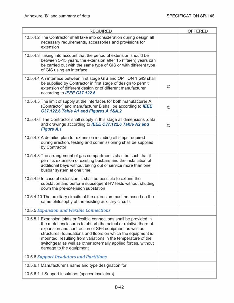
Annexure “B” and summary of data SPECIFICATION SR-148
B-42
REQUIRED OFFERED
10.5.4.2 The Contractor shall take into consideration during design all necessary requirements, accessories and provisions for extension
10.5.4.3 Taking into account that the period of extension should be between 5-15 years, the extension after 15 (fifteen) years can be carried out with the same type of GIS or with different type of GIS using an interface
10.5.4.4 An interface between first stage GIS and OPTION 1 GIS shall be supplied by Contractor in first stage of design to permit extension of different design or of different manufacturer according to IEEE C37.122.6
©
10.5.4.5 The limit of supply at the interfaces for both manufacturer A (Contractor) and manufacturer B shall be according to IEEE C37.122.6 Table A1 and Figures A.1&A.2
©
10.5.4.6 The Contractor shall supply in this stage all dimensions ,data and drawings according to IEEE C37.122.6 Table A2 and Figure A.1
©
10.5.4.7 A detailed plan for extension including all steps required during erection, testing and commissioning shall be supplied by Contractor
10.5.4.8 The arrangement of gas compartments shall be such that it permits extension of existing busbars and the installation of additional bays without taking out of service more than one busbar system at one time
10.5.4.9 In case of extension, it shall be possible to extend the substation and perform subsequent HV tests without shutting down the pre-extension substation
10.5.4.10 The auxiliary circuits of the extension must be based on the same philosophy of the existing auxiliary circuits
Expansion and Flexible Connections 10.5.5
10.5.5.1 Expansion joints or flexible connections shall be provided in the metal enclosures to absorb the actual or relative thermal expansion and contraction of SF6 equipment as well as structures, foundations and floors on which the equipment is mounted, resulting from variations in the temperature of the switchgear as well as other externally applied forces, without damage to the equipment
Support Insulators and Partitions 10.5.6
10.5.6.1 Manufacturer's name and type designation for:
10.5.6.1.1 Support insulators (spacer insulators)

Annexure “B” and summary of data SPECIFICATION SR-148
B-43
REQUIRED OFFERED
10.5.6.1.2 Partitions (gas barrier)
10.5.6.2 The support insulators shall have sufficient strength to ensure that the conductor spacing and clearances are maintained when faults occur
10.5.6.3 In addition to cl. 5.104 in IEC 62271-203, the partitions including seals to the conductor and the enclosure shall be gas-tight and shall be capable of withstanding the maximum pressure differential that could occur across the barrier as follows:
10.5.6.3.1 With a vacuum drawn on the one side of the barrier and, on the other side, at least the maximum gas pressure that can exist under normal operating and maintenance conditions.
Indicate the design pressure of the partitions (bar)
10.5.6.3.2 With maximum gas overpressure at least equal to the operating pressure of the relief devices that could be attained with a persistent internal fault arc unless the barriers have been specifically designed to collapse and act as pressure relief device
10.5.6.3.3 The relation between breaking pressure and design pressure of gas barrier insulators shall be higher than >3
10.5.6.3.4 Indicate the relation between design withstand pressure of partitions and opening pressure of pressure relief device
10.5.6.4 The supporting insulators and partitions shall be free from partial discharge at a voltage level at least 5% above the maximum service voltage
10.5.6.5 Materials used:
10.5.6.5.1 Polyesters
10.5.6.5.2 Epoxies
10.5.6.5.3 Ceramics
10.5.6.5.4 Other material
10.5.6.6 Thermal shock test with preceding and following partial discharge test performed (short description added)
10.5.6.7 Creepage distance for:
10.5.6.7.1 Support insulators (CB/other) (mm/mm)
10.5.6.7.2 Partitions (CB/other) (mm/mm)
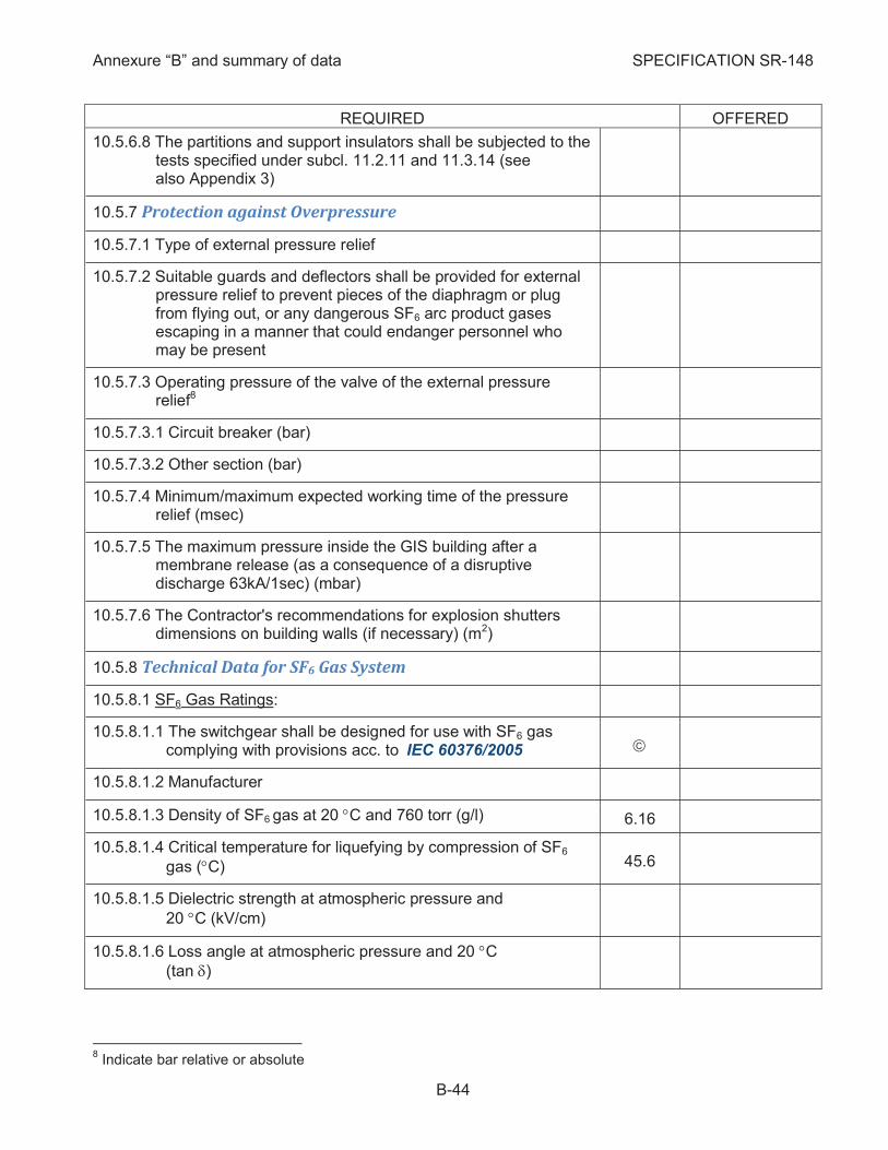
Annexure “B” and summary of data SPECIFICATION SR-148
B-44
REQUIRED OFFERED
10.5.6.8 The partitions and support insulators shall be subjected to the tests specified under subcl. 11.2.11 and 11.3.14 (see also Appendix 3)
Protection against Overpressure 10.5.7
10.5.7.1 Type of external pressure relief
10.5.7.2 Suitable guards and deflectors shall be provided for external pressure relief to prevent pieces of the diaphragm or plug from flying out, or any dangerous SF6 arc product gases escaping in a manner that could endanger personnel who may be present
10.5.7.3 Operating pressure of the valve of the external pressure relief8
10.5.7.3.1 Circuit breaker (bar)
10.5.7.3.2 Other section (bar)
10.5.7.4 Minimum/maximum expected working time of the pressure relief (msec)
10.5.7.5 The maximum pressure inside the GIS building after a membrane release (as a consequence of a disruptive discharge 63kA/1sec) (mbar)
10.5.7.6 The Contractor's recommendations for explosion shutters dimensions on building walls (if necessary) (m2)
Technical Data for SF6 Gas System 10.5.8
10.5.8.1 SF6 Gas Ratings:
10.5.8.1.1 The switchgear shall be designed for use with SF6 gas complying with provisions acc. to IEC 60376/2005 ã
10.5.8.1.2 Manufacturer
10.5.8.1.3 Density of SF6 gas at 20 °C and 760 torr (g/l) 6.16
10.5.8.1.4 Critical temperature for liquefying by compression of SF6
gas (°C) 45.6
10.5.8.1.5 Dielectric strength at atmospheric pressure and
20 °C (kV/cm)
10.5.8.1.6 Loss angle at atmospheric pressure and 20 °C
(tan d)
8 Indicate bar relative or absolute
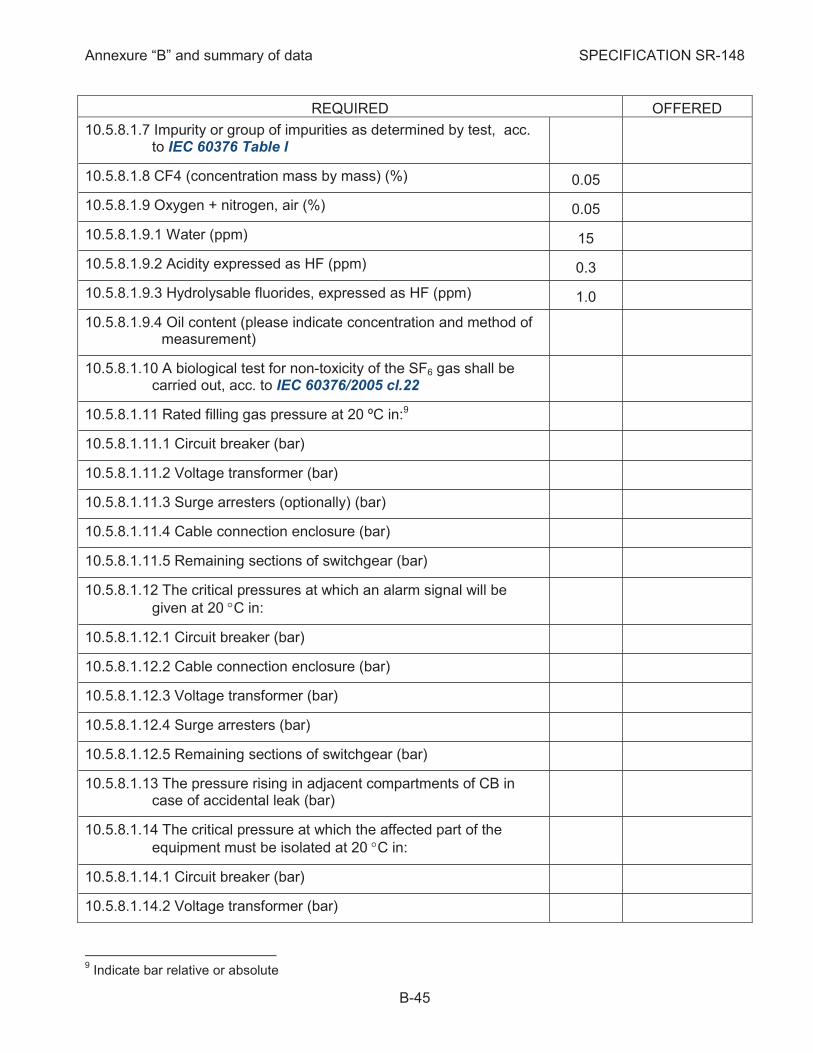
Annexure “B” and summary of data SPECIFICATION SR-148
B-45
REQUIRED OFFERED
10.5.8.1.7 Impurity or group of impurities as determined by test, acc. to IEC 60376 Table l
10.5.8.1.8 CF4 (concentration mass by mass) (%) 0.05
10.5.8.1.9 Oxygen + nitrogen, air (%) 0.05
10.5.8.1.9.1 Water (ppm) 15
10.5.8.1.9.2 Acidity expressed as HF (ppm) 0.3
10.5.8.1.9.3 Hydrolysable fluorides, expressed as HF (ppm) 1.0
10.5.8.1.9.4 Oil content (please indicate concentration and method of measurement)
10.5.8.1.10 A biological test for non-toxicity of the SF6 gas shall be carried out, acc. to IEC 60376/2005 cl.22
10.5.8.1.11 Rated filling gas pressure at 20 ºC in:9
10.5.8.1.11.1 Circuit breaker (bar)
10.5.8.1.11.2 Voltage transformer (bar)
10.5.8.1.11.3 Surge arresters (optionally) (bar)
10.5.8.1.11.4 Cable connection enclosure (bar)
10.5.8.1.11.5 Remaining sections of switchgear (bar)
10.5.8.1.12 The critical pressures at which an alarm signal will be
given at 20 °C in:
10.5.8.1.12.1 Circuit breaker (bar)
10.5.8.1.12.2 Cable connection enclosure (bar)
10.5.8.1.12.3 Voltage transformer (bar)
10.5.8.1.12.4 Surge arresters (bar)
10.5.8.1.12.5 Remaining sections of switchgear (bar)
10.5.8.1.13 The pressure rising in adjacent compartments of CB in case of accidental leak (bar)
10.5.8.1.14 The critical pressure at which the affected part of the
equipment must be isolated at 20 °C in:
10.5.8.1.14.1 Circuit breaker (bar)
10.5.8.1.14.2 Voltage transformer (bar)
9 Indicate bar relative or absolute

Annexure “B” and summary of data SPECIFICATION SR-148
B-46
REQUIRED OFFERED
10.5.8.1.14.3 Cable connection enclosure (bar)
10.5.8.1.14.4 Surge arresters (bar)
10.5.8.1.14.5 Remaining sections of switchgear (bar)
10.5.8.1.15 Maximum pressure rise due to temperature at 50 ºC in:
10.5.8.1.15.1 Circuit breaker (bar)
10.5.8.1.15.2 Voltage transformer (bar)
10.5.8.1.15.3 Cable connection enclosure (bar)
10.5.8.1.15.4 Surge arresters (bar)
10.5.8.1.15.5 Remaining sections of switchgear (bar)
10.5.8.1.16 Rated filling gas density at 20 ºC in:
10.5.8.1.16.1 Circuit breaker (g/l)
10.5.8.1.16.2 Voltage transformer (g/l)
10.5.8.1.16.3 Cable connection enclosure (g/l)
10.5.8.1.16.4 Surge arresters (g/l)
10.5.8.1.16.5 Remaining sections of switchgear (g/l)
10.5.8.1.17 The critical densities at which the alarm signals will be given in:
10.5.8.1.17.1 Circuit breaker (g/l)
10.5.8.1.17.2 Voltage transformer (g/l)
10.5.8.1.17.3 Cable connection enclosure (g/l)
10.5.8.1.17.4 Surge arresters (g/l)
10.5.8.1.17.5 Remaining sections of switchgear (g/l)
10.5.8.1.18 The critical density at which the affected part of the equipment must be isolated in:
10.5.8.1.18.1 Circuit breaker (g/l)
10.5.8.1.18.2 Voltage transformer (g/l)
10.5.8.1.18.3 Cable connection enclosure (g/l)
10.5.8.1.18.4 Surge arresters (g/l)
10.5.8.1.18.5 Remaining sections of switchgear (g/l)
10.5.8.1.19 Dielectric strength at rated density in:
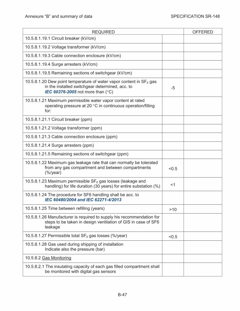
Annexure “B” and summary of data SPECIFICATION SR-148
B-47
REQUIRED OFFERED
10.5.8.1.19.1 Circuit breaker (kV/cm)
10.5.8.1.19.2 Voltage transformer (kV/cm)
10.5.8.1.19.3 Cable connection enclosure (kV/cm)
10.5.8.1.19.4 Surge arresters (kV/cm)
10.5.8.1.19.5 Remaining sections of switchgear (kV/cm)
10.5.8.1.20 Dew point temperature of water vapor content in SF6 gas in the installed switchgear determined, acc. to
IEC 60376-2005 not more than (°C) -5
10.5.8.1.21 Maximum permissible water vapor content at rated
operating pressure at 20 °C in continuous operation/filling for:
10.5.8.1.21.1 Circuit breaker (ppm)
10.5.8.1.21.2 Voltage transformer (ppm)
10.5.8.1.21.3 Cable connection enclosure (ppm)
10.5.8.1.21.4 Surge arresters (ppm)
10.5.8.1.21.5 Remaining sections of switchgear (ppm)
10.5.8.1.22 Maximum gas leakage rate that can normally be tolerated from any gas compartment and between compartments (%/year)
<0.5
10.5.8.1.23 Maximum permissible SF6 gas losses (leakage and handling) for life duration (30 years) for entire substation (%) <1
10.5.8.1.24 The procedure for SF6 handling shall be acc. to IEC 60480/2004 and IEC 62271-4/2013
10.5.8.1.25 Time between refilling (years) >10
10.5.8.1.26 Manufacturer is required to supply his recommendation for steps to be taken in design ventilation of GIS in case of SF6 leakage
10.5.8.1.27 Permissible total SF6 gas losses (%/year) <0.5
10.5.8.1.28 Gas used during shipping of installation Indicate also the pressure (bar)
10.5.8.2 Gas Monitoring
10.5.8.2.1 The insulating capacity of each gas filled compartment shall be monitored with digital gas sensors
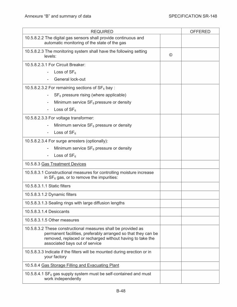
Annexure “B” and summary of data SPECIFICATION SR-148
B-48
REQUIRED OFFERED
10.5.8.2.2 The digital gas sensors shall provide continuous and automatic monitoring of the state of the gas
10.5.8.2.3 The monitoring system shall have the following setting levels: ©
10.5.8.2.3.1 For Circuit Breaker:
- Loss of SF6
- General lock-out
10.5.8.2.3.2 For remaining sections of SF6 bay :
- SF6 pressure rising (where applicable)
- Minimum service SF6 pressure or density
- Loss of SF6
10.5.8.2.3.3 For voltage transformer:
- Minimum service SF6 pressure or density
- Loss of SF6
10.5.8.2.3.4 For surge arresters (optionally):
- Minimum service SF6 pressure or density
- Loss of SF6
10.5.8.3 Gas Treatment Devices
10.5.8.3.1 Constructional measures for controlling moisture increase in SF6 gas, or to remove the impurities:
10.5.8.3.1.1 Static filters
10.5.8.3.1.2 Dynamic filters
10.5.8.3.1.3 Sealing rings with large diffusion lengths
10.5.8.3.1.4 Desiccants
10.5.8.3.1.5 Other measures
10.5.8.3.2 These constructional measures shall be provided as permanent facilities, preferably arranged so that they can be removed, replaced or recharged without having to take the associated bays out of service
10.5.8.3.3 Indicate if the filters will be mounted during erection or in your factory
10.5.8.4 Gas Storage Filling and Evacuating Plant
10.5.8.4.1 SF6 gas supply system must be self-contained and must work independently
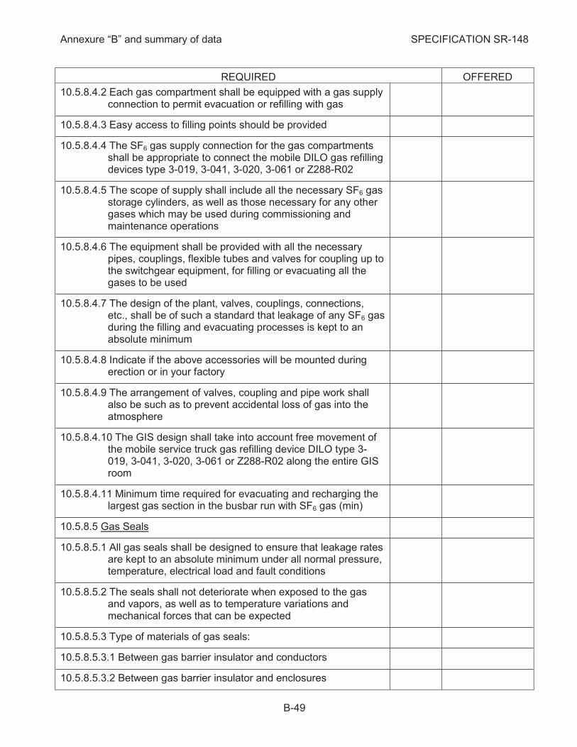
Annexure “B” and summary of data SPECIFICATION SR-148
B-49
REQUIRED OFFERED
10.5.8.4.2 Each gas compartment shall be equipped with a gas supply connection to permit evacuation or refilling with gas
10.5.8.4.3 Easy access to filling points should be provided
10.5.8.4.4 The SF6 gas supply connection for the gas compartments shall be appropriate to connect the mobile DILO gas refilling devices type 3-019, 3-041, 3-020, 3-061 or Z288-R02
10.5.8.4.5 The scope of supply shall include all the necessary SF6 gas storage cylinders, as well as those necessary for any other gases which may be used during commissioning and maintenance operations
10.5.8.4.6 The equipment shall be provided with all the necessary pipes, couplings, flexible tubes and valves for coupling up to the switchgear equipment, for filling or evacuating all the gases to be used
10.5.8.4.7 The design of the plant, valves, couplings, connections, etc., shall be of such a standard that leakage of any SF6 gas during the filling and evacuating processes is kept to an absolute minimum
10.5.8.4.8 Indicate if the above accessories will be mounted during erection or in your factory
10.5.8.4.9 The arrangement of valves, coupling and pipe work shall also be such as to prevent accidental loss of gas into the atmosphere
10.5.8.4.10 The GIS design shall take into account free movement of the mobile service truck gas refilling device DILO type 3-019, 3-041, 3-020, 3-061 or Z288-R02 along the entire GIS room
10.5.8.4.11 Minimum time required for evacuating and recharging the largest gas section in the busbar run with SF6 gas (min)
10.5.8.5 Gas Seals
10.5.8.5.1 All gas seals shall be designed to ensure that leakage rates are kept to an absolute minimum under all normal pressure, temperature, electrical load and fault conditions
10.5.8.5.2 The seals shall not deteriorate when exposed to the gas and vapors, as well as to temperature variations and mechanical forces that can be expected
10.5.8.5.3 Type of materials of gas seals:
10.5.8.5.3.1 Between gas barrier insulator and conductors
10.5.8.5.3.2 Between gas barrier insulator and enclosures
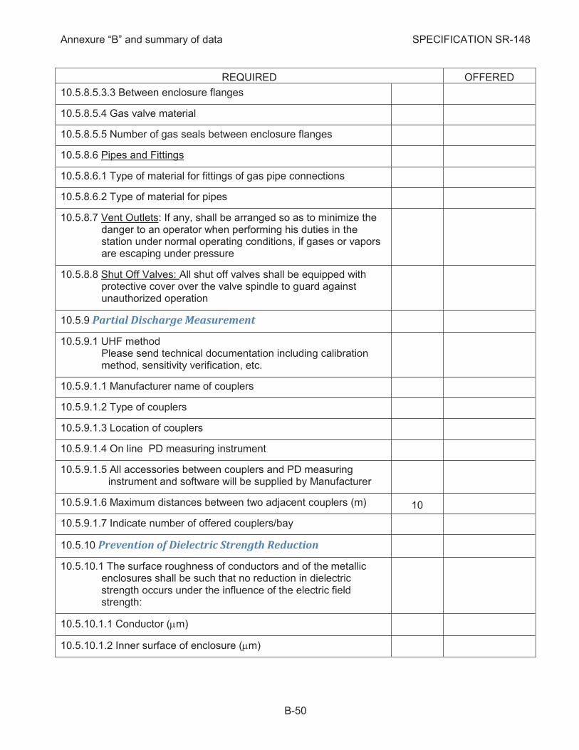
Annexure “B” and summary of data SPECIFICATION SR-148
B-50
REQUIRED OFFERED
10.5.8.5.3.3 Between enclosure flanges
10.5.8.5.4 Gas valve material
10.5.8.5.5 Number of gas seals between enclosure flanges
10.5.8.6 Pipes and Fittings
10.5.8.6.1 Type of material for fittings of gas pipe connections
10.5.8.6.2 Type of material for pipes
10.5.8.7 Vent Outlets: If any, shall be arranged so as to minimize the danger to an operator when performing his duties in the station under normal operating conditions, if gases or vapors are escaping under pressure
10.5.8.8 Shut Off Valves: All shut off valves shall be equipped with protective cover over the valve spindle to guard against unauthorized operation
Partial Discharge Measurement 10.5.9
10.5.9.1 UHF method Please send technical documentation including calibration method, sensitivity verification, etc.
10.5.9.1.1 Manufacturer name of couplers
10.5.9.1.2 Type of couplers
10.5.9.1.3 Location of couplers
10.5.9.1.4 On line PD measuring instrument
10.5.9.1.5 All accessories between couplers and PD measuring instrument and software will be supplied by Manufacturer
10.5.9.1.6 Maximum distances between two adjacent couplers (m) 10
10.5.9.1.7 Indicate number of offered couplers/bay
Prevention of Dielectric Strength Reduction 10.5.10
10.5.10.1 The surface roughness of conductors and of the metallic enclosures shall be such that no reduction in dielectric strength occurs under the influence of the electric field strength:
10.5.10.1.1 Conductor (mm)
10.5.10.1.2 Inner surface of enclosure (mm)
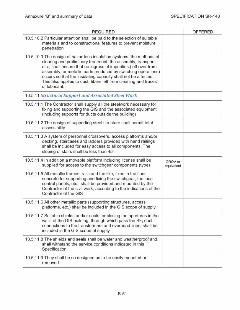
Annexure “B” and summary of data SPECIFICATION SR-148
B-51
REQUIRED OFFERED
10.5.10.2 Particular attention shall be paid to the selection of suitable materials and to constructional features to prevent moisture penetration
10.5.10.3 The design of hazardous insulation systems, the methods of clearing and preliminary treatment, the assembly, transport etc., shall ensure that no ingress of impurities (left over from assembly, or metallic parts produced by switching operations) occurs so that the insulating capacity shall not be affected. This also applies to dust, fibers left from cleaning and traces of lubricant.
Structural Support and Associated Steel Work 10.5.11
10.5.11.1 The Contractor shall supply all the steelwork necessary for fixing and supporting the GIS and the associated equipment (including supports for ducts outside the building)
10.5.11.2 The design of supporting steel structure shall permit total accessibility
10.5.11.3 A system of personnel crossovers, access platforms and/or decking, staircases and ladders provided with hand railings shall be included for easy access to all components. The
sloping of stairs shall be less than 45°
10.5.11.4 In addition a movable platform including license shall be supplied for access to the switchgear components (type)
GROV or equivalent
10.5.11.5 All metallic frames, rails and the like, fixed in the floor concrete for supporting and fixing the switchgear, the local control panels, etc., shall be provided and mounted by the Contractor of the civil work, according to the indications of the Contractor of the GIS
10.5.11.6 All other metallic parts (supporting structures, access platforms, etc.) shall be included in the GIS scope of supply
10.5.11.7 Suitable shields and/or seals for closing the apertures in the walls of the GIS building, through which pass the SF6 duct connections to the transformers and overhead lines, shall be included in the GIS scope of supply
10.5.11.8 The shields and seals shall be water and weatherproof and shall withstand the service conditions indicated in this Specification
10.5.11.9 They shall be so designed as to be easily mounted or removed
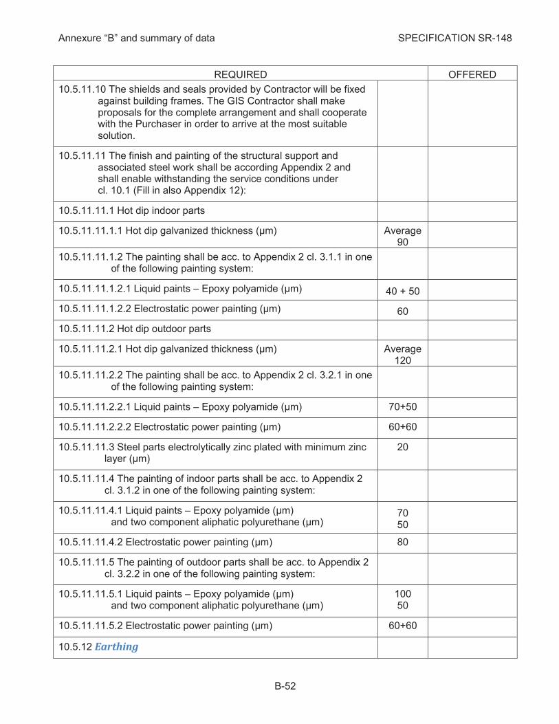
Annexure “B” and summary of data SPECIFICATION SR-148
B-52
REQUIRED OFFERED
10.5.11.10 The shields and seals provided by Contractor will be fixed against building frames. The GIS Contractor shall make proposals for the complete arrangement and shall cooperate with the Purchaser in order to arrive at the most suitable solution.
10.5.11.11 The finish and painting of the structural support and associated steel work shall be according Appendix 2 and shall enable withstanding the service conditions under cl. 10.1 (Fill in also Appendix 12):
10.5.11.11.1 Hot dip indoor parts
10.5.11.11.1.1 Hot dip galvanized thickness (µm) Average 90
10.5.11.11.1.2 The painting shall be acc. to Appendix 2 cl. 3.1.1 in one of the following painting system:
10.5.11.11.1.2.1 Liquid paints – Epoxy polyamide (µm) 40 + 50
10.5.11.11.1.2.2 Electrostatic power painting (µm) 60
10.5.11.11.2 Hot dip outdoor parts
10.5.11.11.2.1 Hot dip galvanized thickness (µm) Average 120
10.5.11.11.2.2 The painting shall be acc. to Appendix 2 cl. 3.2.1 in one of the following painting system:
10.5.11.11.2.2.1 Liquid paints – Epoxy polyamide (µm) 70+50
10.5.11.11.2.2.2 Electrostatic power painting (µm) 60+60
10.5.11.11.3 Steel parts electrolytically zinc plated with minimum zinc layer (µm)
20
10.5.11.11.4 The painting of indoor parts shall be acc. to Appendix 2 cl. 3.1.2 in one of the following painting system:
10.5.11.11.4.1 Liquid paints – Epoxy polyamide (µm) and two component aliphatic polyurethane (µm)
70 50
10.5.11.11.4.2 Electrostatic power painting (µm) 80
10.5.11.11.5 The painting of outdoor parts shall be acc. to Appendix 2 cl. 3.2.2 in one of the following painting system:
10.5.11.11.5.1 Liquid paints – Epoxy polyamide (µm) and two component aliphatic polyurethane (µm)
100 50
10.5.11.11.5.2 Electrostatic power painting (µm) 60+60
Earthing 10.5.12
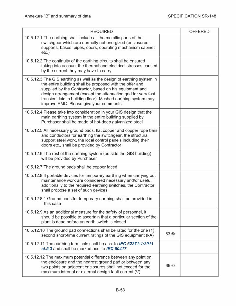
Annexure “B” and summary of data SPECIFICATION SR-148
B-53
REQUIRED OFFERED
10.5.12.1 The earthing shall include all the metallic parts of the switchgear which are normally not energized (enclosures, supports, bases, pipes, doors, operating mechanism cabinet etc.)
10.5.12.2 The continuity of the earthing circuits shall be ensured taking into account the thermal and electrical stresses caused by the current they may have to carry
10.5.12.3 The GIS earthing as well as the design of earthing system in the entire building shall be proposed with the offer and supplied by the Contractor, based on his equipment and design arrangement (except the attenuation grid for very fast transient laid in building floor). Meshed earthing system may improve EMC. Please give your comments
10.5.12.4 Please take into consideration in your GIS design that the main earthing system in the entire building supplied by Purchaser shall be made of hot-deep galvanized steel
10.5.12.5 All necessary ground pads, flat copper and copper rope bars and conductors for earthing the switchgear, the structural support steel work, the local control panels including their doors etc., shall be provided by Contractor
10.5.12.6 The rest of the earthing system (outside the GIS building) will be provided by Purchaser
10.5.12.7 The ground pads shall be copper faced
10.5.12.8 If portable devices for temporary earthing when carrying out maintenance work are considered necessary and/or useful, additionally to the required earthing switches, the Contractor shall propose a set of such devices
10.5.12.8.1 Ground pads for temporary earthing shall be provided in this case
10.5.12.9 As an additional measure for the safety of personnel, it should be possible to ascertain that a particular section of the plant is dead before an earth switch is closed
10.5.12.10 The ground pad connections shall be rated for the one (1) second short-time current ratings of the GIS equipment (kA) 63 ©
10.5.12.11 The earthing terminals shall be acc. to IEC 62271-1/2011 cl.5.3 and shall be marked acc. to IEC 60417
10.5.12.12 The maximum potential difference between any point on the enclosure and the nearest ground pad or between any two points on adjacent enclosures shall not exceed for the maximum internal or external design fault current (V)
65 ©
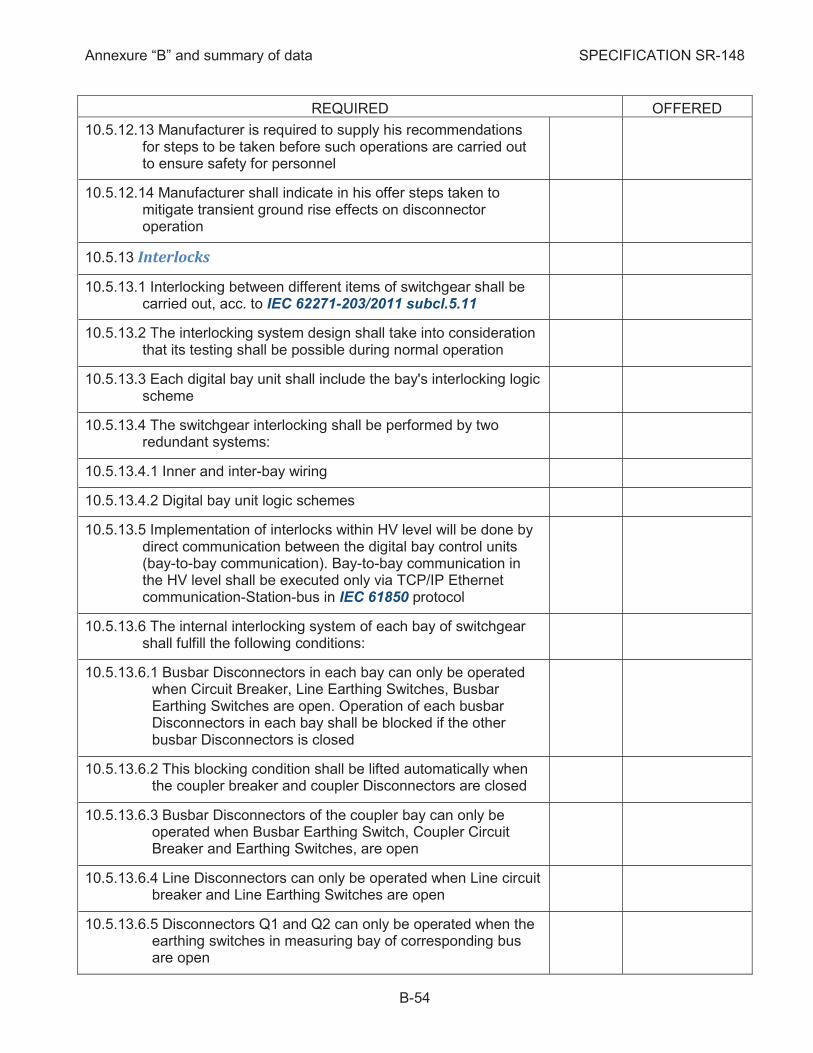
Annexure “B” and summary of data SPECIFICATION SR-148
B-54
REQUIRED OFFERED
10.5.12.13 Manufacturer is required to supply his recommendations for steps to be taken before such operations are carried out to ensure safety for personnel
10.5.12.14 Manufacturer shall indicate in his offer steps taken to mitigate transient ground rise effects on disconnector operation
Interlocks 10.5.13
10.5.13.1 Interlocking between different items of switchgear shall be carried out, acc. to IEC 62271-203/2011 subcl.5.11
10.5.13.2 The interlocking system design shall take into consideration that its testing shall be possible during normal operation
10.5.13.3 Each digital bay unit shall include the bay's interlocking logic scheme
10.5.13.4 The switchgear interlocking shall be performed by two redundant systems:
10.5.13.4.1 Inner and inter-bay wiring
10.5.13.4.2 Digital bay unit logic schemes
10.5.13.5 Implementation of interlocks within HV level will be done by direct communication between the digital bay control units (bay-to-bay communication). Bay-to-bay communication in the HV level shall be executed only via TCP/IP Ethernet communication-Station-bus in IEC 61850 protocol
10.5.13.6 The internal interlocking system of each bay of switchgear shall fulfill the following conditions:
10.5.13.6.1 Busbar Disconnectors in each bay can only be operated when Circuit Breaker, Line Earthing Switches, Busbar Earthing Switches are open. Operation of each busbar Disconnectors in each bay shall be blocked if the other busbar Disconnectors is closed
10.5.13.6.2 This blocking condition shall be lifted automatically when the coupler breaker and coupler Disconnectors are closed
10.5.13.6.3 Busbar Disconnectors of the coupler bay can only be operated when Busbar Earthing Switch, Coupler Circuit Breaker and Earthing Switches, are open
10.5.13.6.4 Line Disconnectors can only be operated when Line circuit breaker and Line Earthing Switches are open
10.5.13.6.5 Disconnectors Q1 and Q2 can only be operated when the earthing switches in measuring bay of corresponding bus are open
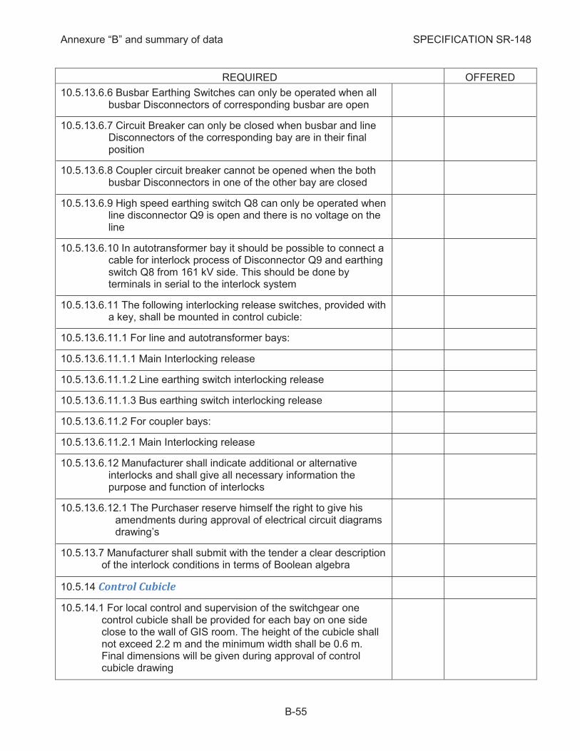
Annexure “B” and summary of data SPECIFICATION SR-148
B-55
REQUIRED OFFERED
10.5.13.6.6 Busbar Earthing Switches can only be operated when all busbar Disconnectors of corresponding busbar are open
10.5.13.6.7 Circuit Breaker can only be closed when busbar and line Disconnectors of the corresponding bay are in their final position
10.5.13.6.8 Coupler circuit breaker cannot be opened when the both busbar Disconnectors in one of the other bay are closed
10.5.13.6.9 High speed earthing switch Q8 can only be operated when line disconnector Q9 is open and there is no voltage on the line
10.5.13.6.10 In autotransformer bay it should be possible to connect a cable for interlock process of Disconnector Q9 and earthing switch Q8 from 161 kV side. This should be done by terminals in serial to the interlock system
10.5.13.6.11 The following interlocking release switches, provided with a key, shall be mounted in control cubicle:
10.5.13.6.11.1 For line and autotransformer bays:
10.5.13.6.11.1.1 Main Interlocking release
10.5.13.6.11.1.2 Line earthing switch interlocking release
10.5.13.6.11.1.3 Bus earthing switch interlocking release
10.5.13.6.11.2 For coupler bays:
10.5.13.6.11.2.1 Main Interlocking release
10.5.13.6.12 Manufacturer shall indicate additional or alternative interlocks and shall give all necessary information the purpose and function of interlocks
10.5.13.6.12.1 The Purchaser reserve himself the right to give his amendments during approval of electrical circuit diagrams drawing’s
10.5.13.7 Manufacturer shall submit with the tender a clear description of the interlock conditions in terms of Boolean algebra
Control Cubicle 10.5.14
10.5.14.1 For local control and supervision of the switchgear one control cubicle shall be provided for each bay on one side close to the wall of GIS room. The height of the cubicle shall not exceed 2.2 m and the minimum width shall be 0.6 m. Final dimensions will be given during approval of control cubicle drawing
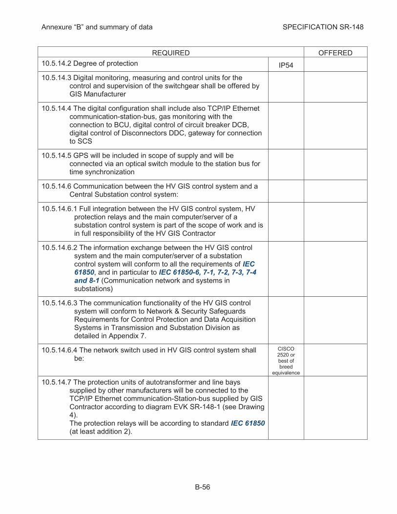
Annexure “B” and summary of data SPECIFICATION SR-148
B-56
REQUIRED OFFERED
10.5.14.2 Degree of protection IP54
10.5.14.3 Digital monitoring, measuring and control units for the control and supervision of the switchgear shall be offered by GIS Manufacturer
10.5.14.4 The digital configuration shall include also TCP/IP Ethernet communication-station-bus, gas monitoring with the connection to BCU, digital control of circuit breaker DCB, digital control of Disconnectors DDC, gateway for connection to SCS
10.5.14.5 GPS will be included in scope of supply and will be connected via an optical switch module to the station bus for time synchronization
10.5.14.6 Communication between the HV GIS control system and a Central Substation control system:
10.5.14.6.1 Full integration between the HV GIS control system, HV protection relays and the main computer/server of a substation control system is part of the scope of work and is in full responsibility of the HV GIS Contractor
10.5.14.6.2 The information exchange between the HV GIS control system and the main computer/server of a substation control system will conform to all the requirements of IEC 61850, and in particular to IEC 61850-6, 7-1, 7-2, 7-3, 7-4 and 8-1 (Communication network and systems in substations)
10.5.14.6.3 The communication functionality of the HV GIS control system will conform to Network & Security Safeguards Requirements for Control Protection and Data Acquisition Systems in Transmission and Substation Division as detailed in Appendix 7.
10.5.14.6.4 The network switch used in HV GIS control system shall be:
CISCO 2520 or best of breed
equivalence
10.5.14.7 The protection units of autotransformer and line bays supplied by other manufacturers will be connected to the TCP/IP Ethernet communication-Station-bus supplied by GIS Contractor according to diagram EVK SR-148-1 (see Drawing 4). The protection relays will be according to standard IEC 61850 (at least addition 2).
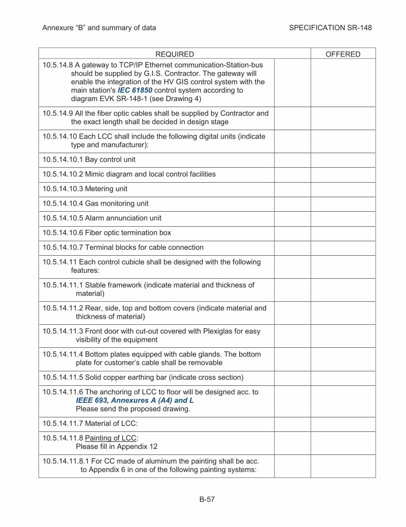
Annexure “B” and summary of data SPECIFICATION SR-148
B-57
REQUIRED OFFERED
10.5.14.8 A gateway to TCP/IP Ethernet communication-Station-bus should be supplied by G.I.S. Contractor. The gateway will enable the integration of the HV GIS control system with the main station's IEC 61850 control system according to diagram EVK SR-148-1 (see Drawing 4)
10.5.14.9 All the fiber optic cables shall be supplied by Contractor and the exact length shall be decided in design stage
10.5.14.10 Each LCC shall include the following digital units (indicate type and manufacturer):
10.5.14.10.1 Bay control unit
10.5.14.10.2 Mimic diagram and local control facilities
10.5.14.10.3 Metering unit
10.5.14.10.4 Gas monitoring unit
10.5.14.10.5 Alarm annunciation unit
10.5.14.10.6 Fiber optic termination box
10.5.14.10.7 Terminal blocks for cable connection
10.5.14.11 Each control cubicle shall be designed with the following features:
10.5.14.11.1 Stable framework (indicate material and thickness of material)
10.5.14.11.2 Rear, side, top and bottom covers (indicate material and thickness of material)
10.5.14.11.3 Front door with cut-out covered with Plexiglas for easy visibility of the equipment
10.5.14.11.4 Bottom plates equipped with cable glands. The bottom plate for customer’s cable shall be removable
10.5.14.11.5 Solid copper earthing bar (indicate cross section)
10.5.14.11.6 The anchoring of LCC to floor will be designed acc. to IEEE 693, Annexures A (A4) and L Please send the proposed drawing.
10.5.14.11.7 Material of LCC:
10.5.14.11.8 Painting of LCC: Please fill in Appendix 12
10.5.14.11.8.1 For CC made of aluminum the painting shall be acc. to Appendix 6 in one of the following painting systems:
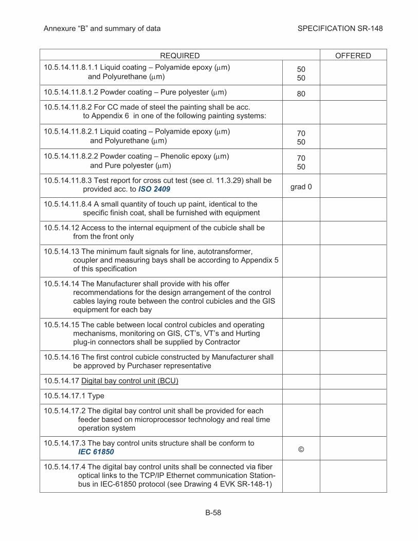
Annexure “B” and summary of data SPECIFICATION SR-148
B-58
REQUIRED OFFERED
10.5.14.11.8.1.1 Liquid coating – Polyamide epoxy (mm)
and Polyurethane (mm) 50 50
10.5.14.11.8.1.2 Powder coating – Pure polyester (mm) 80
10.5.14.11.8.2 For CC made of steel the painting shall be acc. to Appendix 6 in one of the following painting systems:
10.5.14.11.8.2.1 Liquid coating – Polyamide epoxy (mm)
and Polyurethane (mm) 70 50
10.5.14.11.8.2.2 Powder coating – Phenolic epoxy (mm)
and Pure polyester (mm) 70 50
10.5.14.11.8.3 Test report for cross cut test (see cl. 11.3.29) shall be provided acc. to ISO 2409 grad 0
10.5.14.11.8.4 A small quantity of touch up paint, identical to the specific finish coat, shall be furnished with equipment
10.5.14.12 Access to the internal equipment of the cubicle shall be from the front only
10.5.14.13 The minimum fault signals for line, autotransformer, coupler and measuring bays shall be according to Appendix 5 of this specification
10.5.14.14 The Manufacturer shall provide with his offer recommendations for the design arrangement of the control cables laying route between the control cubicles and the GIS equipment for each bay
10.5.14.15 The cable between local control cubicles and operating mechanisms, monitoring on GIS, CT’s, VT’s and Hurting plug-in connectors shall be supplied by Contractor
10.5.14.16 The first control cubicle constructed by Manufacturer shall be approved by Purchaser representative
10.5.14.17 Digital bay control unit (BCU)
10.5.14.17.1 Type
10.5.14.17.2 The digital bay control unit shall be provided for each feeder based on microprocessor technology and real time operation system
10.5.14.17.3 The bay control units structure shall be conform to IEC 61850 ©
10.5.14.17.4 The digital bay control units shall be connected via fiber optical links to the TCP/IP Ethernet communication Station-bus in IEC-61850 protocol (see Drawing 4 EVK SR-148-1)
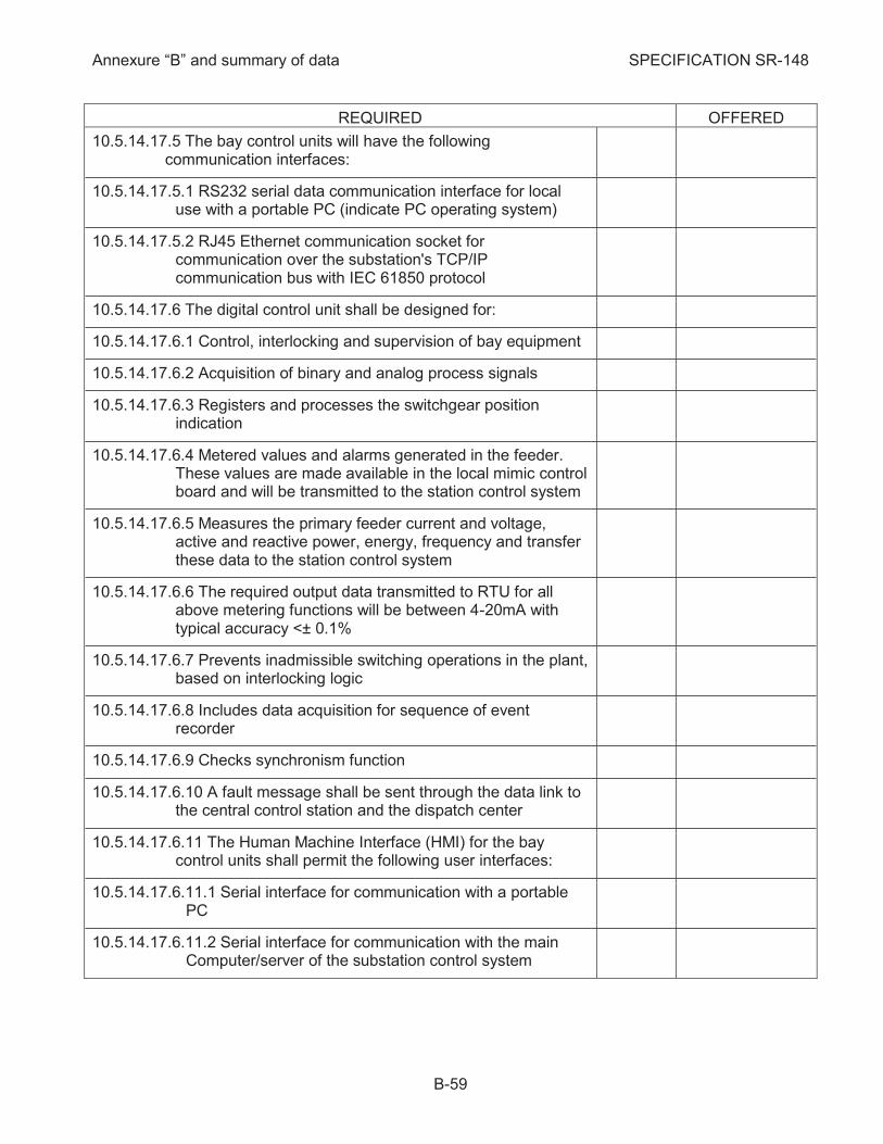
Annexure “B” and summary of data SPECIFICATION SR-148
B-59
REQUIRED OFFERED
10.5.14.17.5 The bay control units will have the following communication interfaces:
10.5.14.17.5.1 RS232 serial data communication interface for local use with a portable PC (indicate PC operating system)
10.5.14.17.5.2 RJ45 Ethernet communication socket for communication over the substation's TCP/IP communication bus with IEC 61850 protocol
10.5.14.17.6 The digital control unit shall be designed for:
10.5.14.17.6.1 Control, interlocking and supervision of bay equipment
10.5.14.17.6.2 Acquisition of binary and analog process signals
10.5.14.17.6.3 Registers and processes the switchgear position indication
10.5.14.17.6.4 Metered values and alarms generated in the feeder. These values are made available in the local mimic control board and will be transmitted to the station control system
10.5.14.17.6.5 Measures the primary feeder current and voltage, active and reactive power, energy, frequency and transfer these data to the station control system
10.5.14.17.6.6 The required output data transmitted to RTU for all above metering functions will be between 4-20mA with typical accuracy <± 0.1%
10.5.14.17.6.7 Prevents inadmissible switching operations in the plant, based on interlocking logic
10.5.14.17.6.8 Includes data acquisition for sequence of event recorder
10.5.14.17.6.9 Checks synchronism function
10.5.14.17.6.10 A fault message shall be sent through the data link to the central control station and the dispatch center
10.5.14.17.6.11 The Human Machine Interface (HMI) for the bay control units shall permit the following user interfaces:
10.5.14.17.6.11.1 Serial interface for communication with a portable PC
10.5.14.17.6.11.2 Serial interface for communication with the main Computer/server of the substation control system
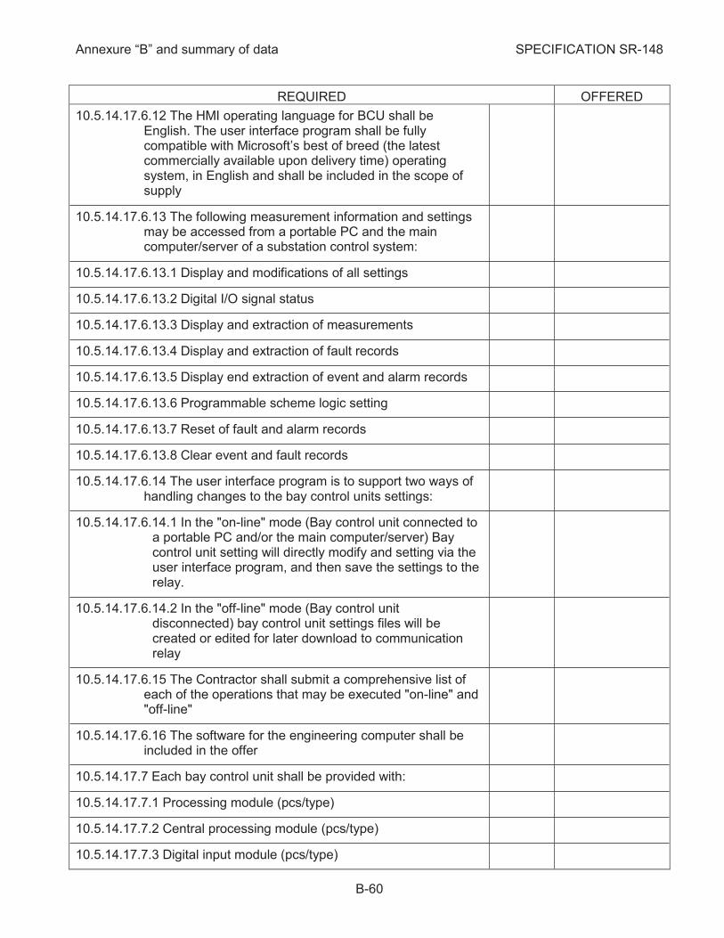
Annexure “B” and summary of data SPECIFICATION SR-148
B-60
REQUIRED OFFERED
10.5.14.17.6.12 The HMI operating language for BCU shall be English. The user interface program shall be fully compatible with Microsoft’s best of breed (the latest commercially available upon delivery time) operating system, in English and shall be included in the scope of supply
10.5.14.17.6.13 The following measurement information and settings may be accessed from a portable PC and the main computer/server of a substation control system:
10.5.14.17.6.13.1 Display and modifications of all settings
10.5.14.17.6.13.2 Digital I/O signal status
10.5.14.17.6.13.3 Display and extraction of measurements
10.5.14.17.6.13.4 Display and extraction of fault records
10.5.14.17.6.13.5 Display end extraction of event and alarm records
10.5.14.17.6.13.6 Programmable scheme logic setting
10.5.14.17.6.13.7 Reset of fault and alarm records
10.5.14.17.6.13.8 Clear event and fault records
10.5.14.17.6.14 The user interface program is to support two ways of handling changes to the bay control units settings:
10.5.14.17.6.14.1 In the "on-line" mode (Bay control unit connected to a portable PC and/or the main computer/server) Bay control unit setting will directly modify and setting via the user interface program, and then save the settings to the relay.
10.5.14.17.6.14.2 In the "off-line" mode (Bay control unit disconnected) bay control unit settings files will be created or edited for later download to communication relay
10.5.14.17.6.15 The Contractor shall submit a comprehensive list of each of the operations that may be executed "on-line" and "off-line"
10.5.14.17.6.16 The software for the engineering computer shall be included in the offer
10.5.14.17.7 Each bay control unit shall be provided with:
10.5.14.17.7.1 Processing module (pcs/type)
10.5.14.17.7.2 Central processing module (pcs/type)
10.5.14.17.7.3 Digital input module (pcs/type)
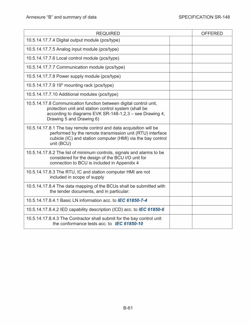
Annexure “B” and summary of data SPECIFICATION SR-148
B-61
REQUIRED OFFERED
10.5.14.17.7.4 Digital output module (pcs/type)
10.5.14.17.7.5 Analog input module (pcs/type)
10.5.14.17.7.6 Local control module (pcs/type)
10.5.14.17.7.7 Communication module (pcs/type)
10.5.14.17.7.8 Power supply module (pcs/type)
10.5.14.17.7.9 19" mounting rack (pcs/type)
10.5.14.17.7.10 Additional modules (pcs/type)
10.5.14.17.8 Communication function between digital control unit, protection unit and station control system (shall be according to diagrams EVK SR-148-1,2,3 – see Drawing 4, Drawing 5 and Drawing 6)
10.5.14.17.8.1 The bay remote control and data acquisition will be performed by the remote transmission unit (RTU) interface cubicle (IC) and station computer (HMI) via the bay control unit (BCU)
10.5.14.17.8.2 The list of minimum controls, signals and alarms to be considered for the design of the BCU I/O unit for connection to BCU is included in Appendix 4
10.5.14.17.8.3 The RTU, IC and station computer HMI are not included in scope of supply
10.5.14.17.8.4 The data mapping of the BCUs shall be submitted with the tender documents, and in particular:
10.5.14.17.8.4.1 Basic LN information acc. to IEC 61850-7-4
10.5.14.17.8.4.2 IED capability description (ICD) acc. to IEC 61850-6
10.5.14.17.8.4.3 The Contractor shall submit for the bay control unit the conformance tests acc. to IEC 61850-10

Annexure “B” and summary of data SPECIFICATION SR-148
B-62
REQUIRED OFFERED
10.5.14.17.8.5 The control can be activated both from dispatch center and from local control room When the Local/Remote selector switch of the switchgear is in the Remote position two sources of control to the switchgear are possible (diagram EVK-SR-148-3 – see Drawing 6): a. Station – control from HMI of the control system (station level) b. Tele – Control from the dispatch center Only one of the control sources may by active at a given time. The selection of the active source of control is done from the HMI of the control system. The digital bay control units shall be equipped with two changeover relay outputs for transferring the 60V DC control voltage between the digital bay control units control output-contacts (station) and output-contacts of the Remote Terminal Units of the dispatch center (Tele). The default position of those changeover outputs is in the "Tele" position (i.e. when the digital bay control units are de-energized, or after digital bay control units initiation or re-start). A N/O signaling output of the digital bay control units will be allocated for remote signaling of "Station" position of the Tele/Station change-over outputs.
10.5.14.17.8.6 The digital bay control units shall acquire all bay-relevant process data, and time tags them at resolutions of 1ms. Time synchronization on the digital bay control units will be according to Appendix 13)
10.5.14.17.8.7 The digital bay control units will be provided with the required non-volatile memory for storage of at least: 200 time-tagged event records
10.5.14.17.8.8 The digital bay control units shall include programmable scheme logic that allows customizing the control functions, and to program the functionality of the optically isolated inputs, relay outputs and LED indications. The programmable scheme logic comprises gate logic and general-purpose timers. The programmable scheme logic configuration-software shall be fully compatible with Microsoft’s best of breed (the latest commercially available upon delivery time) operating system, in English and included in scope of supply.

Annexure “B” and summary of data SPECIFICATION SR-148
B-63
REQUIRED OFFERED
10.5.14.17.8.9 Voltage range of Power Supply Unit of the digital bay control units will be: Two redundant Power Supply Units for digital bay unit shall be done
220Vdc +10% -15%
10.5.14.17.8.10 Each digital bay control unit shall be provided with self-supervision, which continuously monitors the state of the critical functions. The events or alarms can be transferred via communication system to the station control system
10.5.14.17.8.11 Each digital bay control unit shall be provided with a normal/emergency switch
10.5.14.17.8.12 In case of failure of control, the digital control unit will be local operated on emergency status from normal/emergency switch
10.5.14.17.8.13 All digital control units are completely independent from each other and from Station-bus interface. In case of failure in communication system all events will be registered by the bay control units
10.5.14.17.8.14 Complete schemes of measuring, control, alarm, interlocking, etc. circuits, as well as the wiring schemes for switchgear shall be supplied
10.5.14.17.8.15 Additional special functions like data transfer programming, etc. shall be performed from an engineering PC included in the offer
10.5.14.18 Mimic diagram and local control facilities:
10.5.14.18.1 A mimic diagram with all necessary position indicators shall be provided on the face of the LCC, so that clear and complete indication is given at any time on the position of the breakers, Disconnectors and Earthing switches in each bay
10.5.14.18.2 Position indicators for CB, Disconnectors and Earthing switches shall be provided with three indicating positions: (1) open, (2) close, (3) no voltage
10.5.14.18.3 A common local/remote selector switch for CB and all Disconnectors of each bay) shall be mounted in control cubicle for selecting the desired mode of operation
10.5.14.18.4 For each line high speed earthing switch the push buttons shall be provided with a key
10.5.14.18.5 Green and red push buttons shall be mounted in control cubicle for local opening (red) and closing (green) of all switching device except line high-speed earthing switches
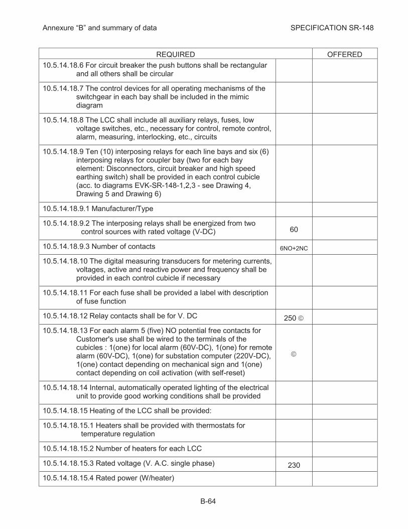
Annexure “B” and summary of data SPECIFICATION SR-148
B-64
REQUIRED OFFERED
10.5.14.18.6 For circuit breaker the push buttons shall be rectangular and all others shall be circular
10.5.14.18.7 The control devices for all operating mechanisms of the switchgear in each bay shall be included in the mimic diagram
10.5.14.18.8 The LCC shall include all auxiliary relays, fuses, low voltage switches, etc., necessary for control, remote control, alarm, measuring, interlocking, etc., circuits
10.5.14.18.9 Ten (10) interposing relays for each line bays and six (6) interposing relays for coupler bay (two for each bay element: Disconnectors, circuit breaker and high speed earthing switch) shall be provided in each control cubicle (acc. to diagrams EVK-SR-148-1,2,3 - see Drawing 4, Drawing 5 and Drawing 6)
10.5.14.18.9.1 Manufacturer/Type
10.5.14.18.9.2 The interposing relays shall be energized from two control sources with rated voltage (V-DC) 60
10.5.14.18.9.3 Number of contacts 6NO+2NC
10.5.14.18.10 The digital measuring transducers for metering currents, voltages, active and reactive power and frequency shall be provided in each control cubicle if necessary
10.5.14.18.11 For each fuse shall be provided a label with description of fuse function
10.5.14.18.12 Relay contacts shall be for V. DC 250 ã
10.5.14.18.13 For each alarm 5 (five) NO potential free contacts for Customer's use shall be wired to the terminals of the cubicles : 1(one) for local alarm (60V-DC), 1(one) for remote alarm (60V-DC), 1(one) for substation computer (220V-DC), 1(one) contact depending on mechanical sign and 1(one) contact depending on coil activation (with self-reset)
ã
10.5.14.18.14 Internal, automatically operated lighting of the electrical unit to provide good working conditions shall be provided
10.5.14.18.15 Heating of the LCC shall be provided:
10.5.14.18.15.1 Heaters shall be provided with thermostats for temperature regulation
10.5.14.18.15.2 Number of heaters for each LCC
10.5.14.18.15.3 Rated voltage (V. A.C. single phase) 230
10.5.14.18.15.4 Rated power (W/heater)
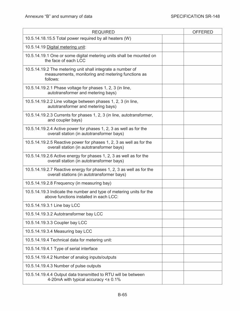
Annexure “B” and summary of data SPECIFICATION SR-148
B-65
REQUIRED OFFERED
10.5.14.18.15.5 Total power required by all heaters (W)
10.5.14.19 Digital metering unit:
10.5.14.19.1 One or some digital metering units shall be mounted on the face of each LCC
10.5.14.19.2 The metering unit shall integrate a number of measurements, monitoring and metering functions as follows:
10.5.14.19.2.1 Phase voltage for phases 1, 2, 3 (in line, autotransformer and metering bays)
10.5.14.19.2.2 Line voltage between phases 1, 2, 3 (in line, autotransformer and metering bays)
10.5.14.19.2.3 Currents for phases 1, 2, 3 (in line, autotransformer, and coupler bays)
10.5.14.19.2.4 Active power for phases 1, 2, 3 as well as for the overall station (in autotransformer bays)
10.5.14.19.2.5 Reactive power for phases 1, 2, 3 as well as for the overall station (in autotransformer bays)
10.5.14.19.2.6 Active energy for phases 1, 2, 3 as well as for the overall station (in autotransformer bays)
10.5.14.19.2.7 Reactive energy for phases 1, 2, 3 as well as for the overall stations (in autotransformer bays)
10.5.14.19.2.8 Frequency (in measuring bay)
10.5.14.19.3 Indicate the number and type of metering units for the above functions installed in each LCC:
10.5.14.19.3.1 Line bay LCC
10.5.14.19.3.2 Autotransformer bay LCC
10.5.14.19.3.3 Coupler bay LCC
10.5.14.19.3.4 Measuring bay LCC
10.5.14.19.4 Technical data for metering unit:
10.5.14.19.4.1 Type of serial interface
10.5.14.19.4.2 Number of analog inputs/outputs
10.5.14.19.4.3 Number of pulse outputs
10.5.14.19.4.4 Output data transmitted to RTU will be between 4-20mA with typical accuracy <± 0.1%

Annexure “B” and summary of data SPECIFICATION SR-148
B-66
REQUIRED OFFERED
10.5.14.20 Gas monitoring system Gas monitoring system can be in a separate system or can be integrated in BCU and shall include:
10.5.14.20.1 Sensors in each gas compartment (indicate type and manufacturer of sensor)
10.5.14.20.2 All sensors of each bay will communicate with the gas module via serial link (indicate type and manufacturer of gas module)
10.5.14.20.3 The gas module shall perform the following monitoring functions:
10.5.14.20.3.1 Gas density calculation based on pressure and temperature acquisition and alarms
10.5.14.20.3.2 Monitoring of gas sensors
10.5.14.20.3.3 Gas leakage measurements and alarms
10.5.14.20.3.4 Management of gas compartment re-filling and enclosure overheating detection
10.5.14.20.3.5 Internal arc detection
10.5.14.20.4 A local HMI will be fitted on the LCC front panel for display current density reading of each gas compartment and alarm functions
10.5.14.20.5 The gas module in one bay will communicate via fiber optics network of communication link with bay control unit and other gas modules in GIS bays
10.5.14.20.6 The preprocessed density data from gas modules will be transmitted to central unit via optical bus
10.5.14.20.7 The central unit processes and visualizes gas density data for entire substation
10.5.14.20.8 The digital gas monitoring system shall have the following communication interfaces: a. RS232 serial data communication interface for use locally with a portable PC (the required software for the PC shall be fully compatible with Microsoft’s best of breed (the latest commercially available upon delivery time) operating system, and will be supplied with the digital gas module). b. RJ45 Ethernet communication socket for communication over the substation's TCP/IP communication bus with IEC 61850 protocol
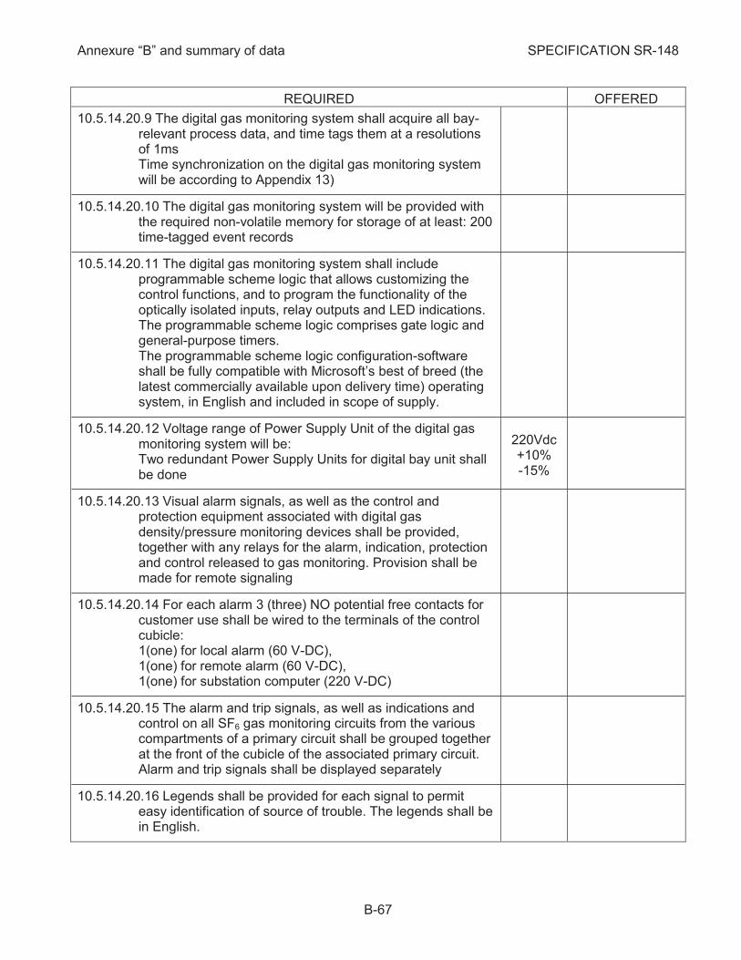
Annexure “B” and summary of data SPECIFICATION SR-148
B-67
REQUIRED OFFERED
10.5.14.20.9 The digital gas monitoring system shall acquire all bay-relevant process data, and time tags them at a resolutions of 1ms Time synchronization on the digital gas monitoring system will be according to Appendix 13)
10.5.14.20.10 The digital gas monitoring system will be provided with the required non-volatile memory for storage of at least: 200 time-tagged event records
10.5.14.20.11 The digital gas monitoring system shall include programmable scheme logic that allows customizing the control functions, and to program the functionality of the optically isolated inputs, relay outputs and LED indications. The programmable scheme logic comprises gate logic and general-purpose timers. The programmable scheme logic configuration-software shall be fully compatible with Microsoft’s best of breed (the latest commercially available upon delivery time) operating system, in English and included in scope of supply.
10.5.14.20.12 Voltage range of Power Supply Unit of the digital gas monitoring system will be: Two redundant Power Supply Units for digital bay unit shall be done
220Vdc +10% -15%
10.5.14.20.13 Visual alarm signals, as well as the control and protection equipment associated with digital gas density/pressure monitoring devices shall be provided, together with any relays for the alarm, indication, protection and control released to gas monitoring. Provision shall be made for remote signaling
10.5.14.20.14 For each alarm 3 (three) NO potential free contacts for customer use shall be wired to the terminals of the control cubicle: 1(one) for local alarm (60 V-DC), 1(one) for remote alarm (60 V-DC), 1(one) for substation computer (220 V-DC)
10.5.14.20.15 The alarm and trip signals, as well as indications and control on all SF6 gas monitoring circuits from the various compartments of a primary circuit shall be grouped together at the front of the cubicle of the associated primary circuit. Alarm and trip signals shall be displayed separately
10.5.14.20.16 Legends shall be provided for each signal to permit easy identification of source of trouble. The legends shall be in English.

Annexure “B” and summary of data SPECIFICATION SR-148
B-68
REQUIRED OFFERED
10.5.14.20.17 The control and protection circuits associated with the gas monitoring devices shall be supplied with the switchgear as part of this Contract
10.5.14.20.18 Complete scheme of SF6 gas monitoring, alarm, indicating etc., circuits, as well as the wiring schemes to all devices involved in these circuits, shall be supplied
10.5.14.21 The training course shall include also the digital control and one line monitoring of GIS
10.5.14.22 The list of spare parts shall include also spare parts for digital control proposal
10.5.14.23 The Purchaser shall be informed by Contractor about all improvements connected to digital control and one line monitoring
10.5.14.24 The digital local control shall be combined with one line monitors and all metered values will be transmitted to the station control system (indicate type of each of them):
10.5.14.24.1 On-line monitoring of CB operation time (DBC- see subcl. 10.5.19.3.28)
10.5.14.24.2 On line monitoring of CB mechanism
10.5.14.24.3 On-line monitoring of Disconnectors and earthing switches (DDC see subcl. 10.5.20.4.28)
10.5.14.24.4 On line monitoring of SF6 density in each compartment (see subcl. 10.5.14.20.1)
10.5.14.24.5 On line monitoring of PD (see subcl. 10.5.9.1.4)
10.5.14.24.6 On line internal arc detection (see subcl. 10.5.14.20.3.5)
10.5.14.25 Legends (in English) shall be provided for all schemes and for each signal
10.5.14.26 The control cubicle shall be EMI proofed
10.5.14.27 Details of the circuits in the control cubicle as well as design details will be settled between Contractor and Purchaser
10.5.14.28 Modifications of LCC in design stage shall not involve additional prices
Auxiliary and Control Circuits 10.5.15
10.5.15.1 The auxiliary and control circuits and devices, as well as the wiring shall be executed and mounted, acc. to IEC 62271-203 /2011 and IEC 62271-1/2011 subcl.5.4

Annexure “B” and summary of data SPECIFICATION SR-148
B-69
REQUIRED OFFERED
10.5.15.2 The graphical symbols for diagrams shall be according to IEC 60617/2012
10.5.15.3 All denomination used by manufacturer shall be according to the Item Designation in Electrotechnologie standard IEC 81346/2009
10.5.15.4 Unless otherwise required in this Specification, control wiring, terminal blocks, arrangement of wiring shall be designed according to Israel Electric Co. standard EPD-A.03/2004 APPENDIX 8
10.5.15.5 The Purchaser can furnish the following power supply voltages:
10.5.15.5.1 Heating purposes (V- AC single phase) 230
10.5.15.5.2 Motor of operating mechanism (V -DC) 220 (+10% -15%)
10.5.15.5.3 Control circuits (V -DC) 220 (+10% -15%)
10.5.15.5.4 Alarm circuits for substation computer (V-DC) 220 (+10% -15%)
10.5.15.5.5 Other alarm circuits (V -DC) 60 (+10% -15%)
10.5.15.6 All wiring and cables from CT's, VT's, gas sensors and operating mechanisms shall be mounted in screen-covered ducts fixed on support structure
10.5.15.7 All wiring for auxiliary equipment and operating devices for connection to Purchaser's cables shall be terminated at terminal blocks in control cubicle
10.5.15.8 Current circuits and voltage circuits shall be in separate cables
10.5.15.9 Control circuits and power circuits shall be in separate cable
10.5.15.10 D.C. voltage distribution to the control cubicles shall be according to drawing no. EVK- 6998 (see Drawing 7). Separate cables shall be provided for DC1, DC2 and AC circuits
10.5.15.11 Contractor shall supply all cables for interlocking purposes between control cubicles
10.5.15.12 Control circuits to the two tripping coils shall be in separate cables
10.5.15.13 Terminals:
10.5.15.13.1 Type of terminals shall be as follows:
10.5.15.13.1.1 Current circuits (16 mm2, 500V) Phoenix UGSK/s

Annexure “B” and summary of data SPECIFICATION SR-148
B-70
REQUIRED OFFERED
10.5.15.13.1.2 Voltage circuits (16 mm2, 500V) Phoenix URTK/s
10.5.15.13.1.3 Control and alarm circuits (10 mm2, 750V) Phoenix UK 6N
10.5.15.13.1.4 Remote signal and alarm circuits (1.5-4 mm2, 750V) Phoenix UK 6N
10.5.15.13.2 Each terminal block shall be provided with not less than 10% spare terminals
10.5.15.13.3 The blocks shall be spaced to allow ample clearance on all sides
10.5.15.13.4 The terminals shall be with facility for plug connection on both sides for circuit breakers and disconnectors (indicate type)
10.5.15.13.5 The connection between control cubicles and interface cubicles shall be through terminals
10.5.15.14 Wiring:
10.5.15.14.1 Wiring shall be carried out with flexible conductors with a preferred cross section as follow:
10.5.15.14.1.1 Control and alarm circuits with current lower than 0.5 A (mm2) 1.5
10.5.15.14.1.2 Control and alarm circuits with current higher than 0.5 A (mm2) 2.5
10.5.15.14.1.3 CT secondary circuits (mm2) 6
10.5.15.14.1.4 VT secondary circuits (mm2) 4
10.5.15.14.2 The wires with XLPE insulation shall be for 1000V rated voltage
10.5.15.14.3 In case of connection by means of sockets, the Contractor shall supply spare pins (minimum 5) for Purchaser’s spare cores in cables as well as spare wiring (minimum 5) from sockets to bays switchgear. Please indicate the number of spare pins and wiring provided.
10.5.15.14.4 The type of sockets shall be Hurting type
10.5.15.14.5 EMC requirements shall be taken into consideration in all phases of planning the layout of the GIS equipment acc. to IEC 62271-203/2011 cl.6.9
10.5.15.14.6 The contractor shall use a combined EMC hardened secondary cables and EMC hardened connectors with a minimum transfer impedance
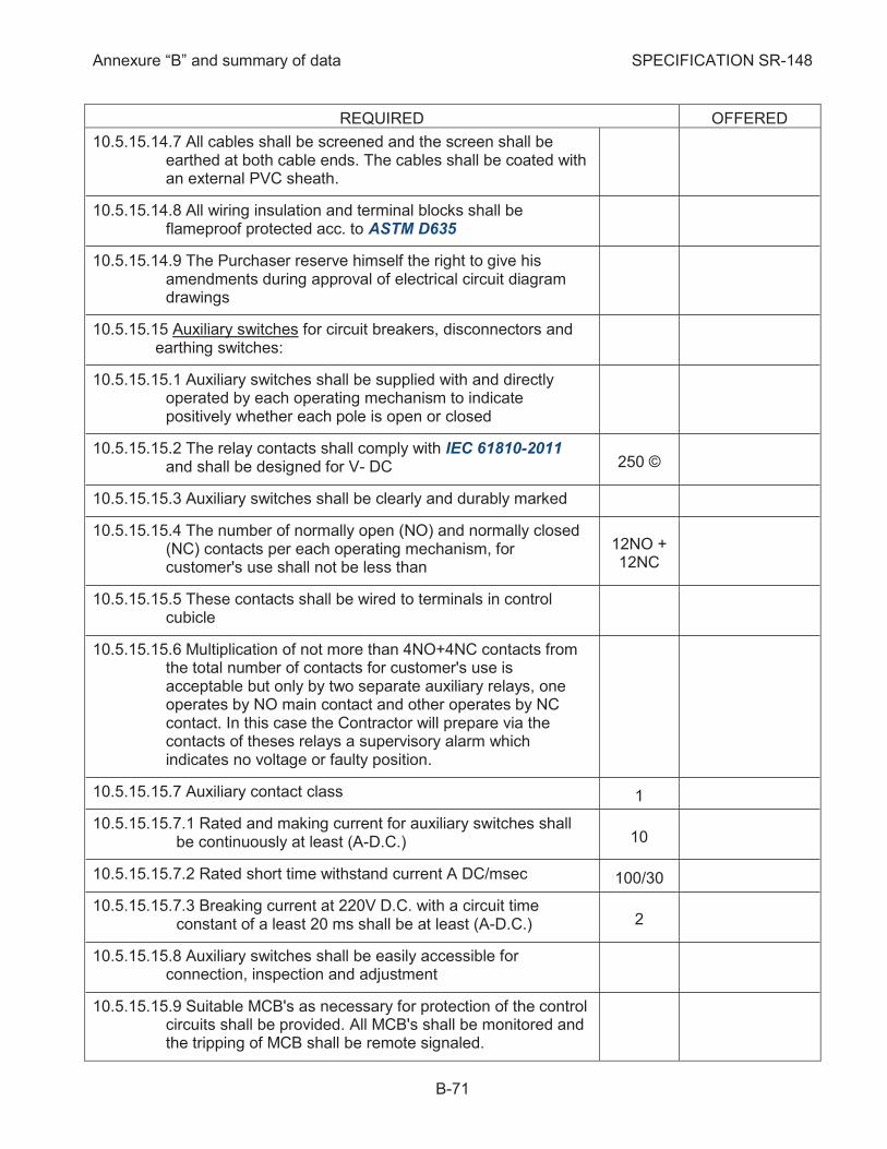
Annexure “B” and summary of data SPECIFICATION SR-148
B-71
REQUIRED OFFERED
10.5.15.14.7 All cables shall be screened and the screen shall be earthed at both cable ends. The cables shall be coated with an external PVC sheath.
10.5.15.14.8 All wiring insulation and terminal blocks shall be flameproof protected acc. to ASTM D635
10.5.15.14.9 The Purchaser reserve himself the right to give his amendments during approval of electrical circuit diagram drawings
10.5.15.15 Auxiliary switches for circuit breakers, disconnectors and earthing switches:
10.5.15.15.1 Auxiliary switches shall be supplied with and directly operated by each operating mechanism to indicate positively whether each pole is open or closed
10.5.15.15.2 The relay contacts shall comply with IEC 61810-2011 and shall be designed for V- DC 250 ©
10.5.15.15.3 Auxiliary switches shall be clearly and durably marked
10.5.15.15.4 The number of normally open (NO) and normally closed (NC) contacts per each operating mechanism, for customer's use shall not be less than
12NO + 12NC
10.5.15.15.5 These contacts shall be wired to terminals in control cubicle
10.5.15.15.6 Multiplication of not more than 4NO+4NC contacts from the total number of contacts for customer's use is acceptable but only by two separate auxiliary relays, one operates by NO main contact and other operates by NC contact. In this case the Contractor will prepare via the contacts of theses relays a supervisory alarm which indicates no voltage or faulty position.
10.5.15.15.7 Auxiliary contact class 1
10.5.15.15.7.1 Rated and making current for auxiliary switches shall be continuously at least (A-D.C.) 10
10.5.15.15.7.2 Rated short time withstand current A DC/msec 100/30
10.5.15.15.7.3 Breaking current at 220V D.C. with a circuit time constant of a least 20 ms shall be at least (A-D.C.) 2
10.5.15.15.8 Auxiliary switches shall be easily accessible for connection, inspection and adjustment
10.5.15.15.9 Suitable MCB's as necessary for protection of the control circuits shall be provided. All MCB's shall be monitored and the tripping of MCB shall be remote signaled.
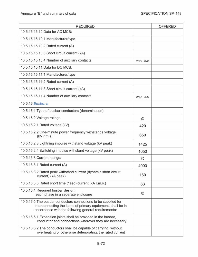
Annexure “B” and summary of data SPECIFICATION SR-148
B-72
REQUIRED OFFERED
10.5.15.15.10 Data for AC MCB:
10.5.15.15.10.1 Manufacturer/type
10.5.15.15.10.2 Rated current (A)
10.5.15.15.10.3 Short circuit current (kA)
10.5.15.15.10.4 Number of auxiliary contacts 2NO +2NC
10.5.15.15.11 Data for DC MCB:
10.5.15.15.11.1 Manufacturer/type
10.5.15.15.11.2 Rated current (A)
10.5.15.15.11.3 Short circuit current (kA)
10.5.15.15.11.4 Number of auxiliary contacts 2NO +2NC
Busbars 10.5.16
10.5.16.1 Type of busbar conductors (denomination)
10.5.16.2 Voltage ratings: ©
10.5.16.2.1 Rated voltage (kV) 420
10.5.16.2.2 One-minute power frequency withstands voltage (kV r.m.s.) 650
10.5.16.2.3 Lightning impulse withstand voltage (kV peak) 1425
10.5.16.2.4 Switching impulse withstand voltage (kV peak) 1050
10.5.16.3 Current ratings: ©
10.5.16.3.1 Rated current (A) 4000
10.5.16.3.2 Rated peak withstand current (dynamic short circuit current) (kA peak) 160
10.5.16.3.3 Rated short time (1sec) current (kA r.m.s.) 63
10.5.16.4 Required busbar design: each phase in a separate enclosure ©
10.5.16.5 The busbar conductors connections to be supplied for interconnecting the items of primary equipment, shall be in accordance with the following general requirements:
10.5.16.5.1 Expansion joints shall be provided in the busbar, conductor and connections wherever they are necessary
10.5.16.5.2 The conductors shall be capable of carrying, without overheating or otherwise deteriorating, the rated current
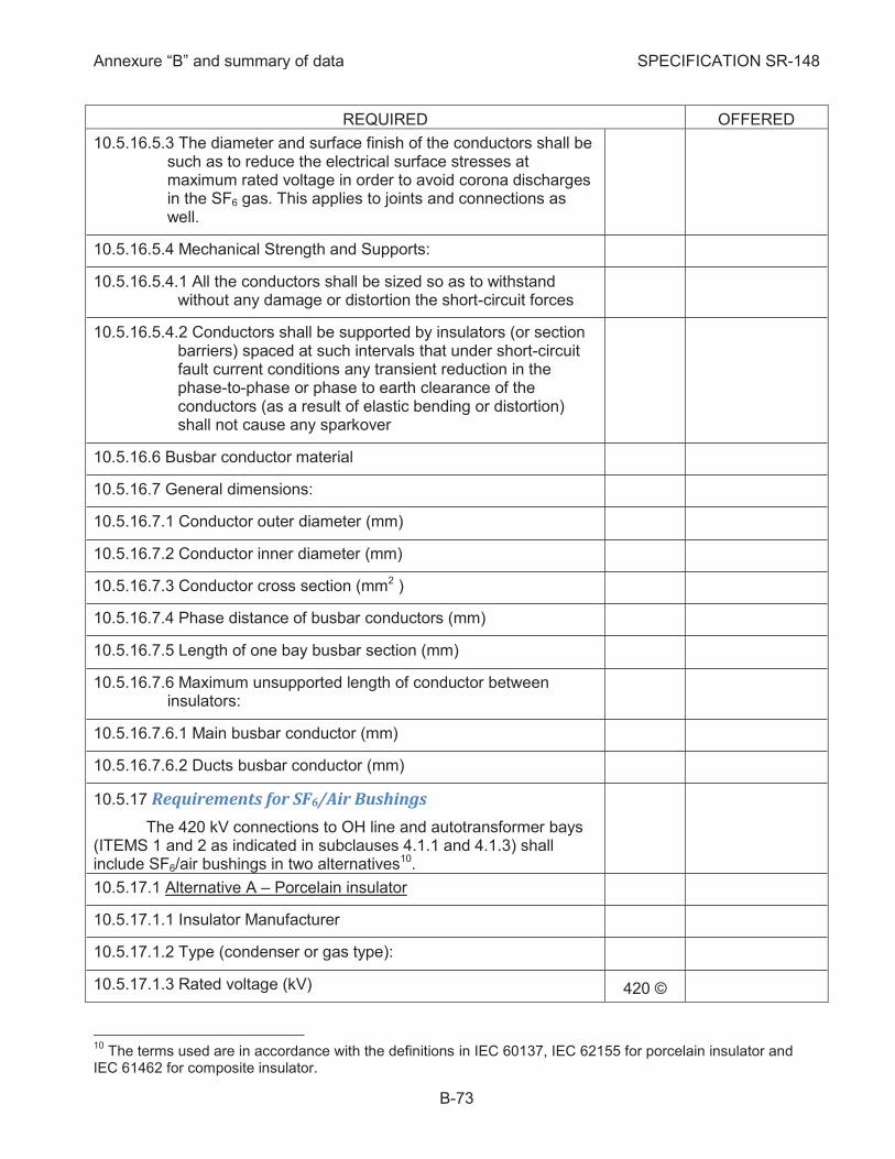
Annexure “B” and summary of data SPECIFICATION SR-148
B-73
REQUIRED OFFERED
10.5.16.5.3 The diameter and surface finish of the conductors shall be such as to reduce the electrical surface stresses at maximum rated voltage in order to avoid corona discharges in the SF6 gas. This applies to joints and connections as well.
10.5.16.5.4 Mechanical Strength and Supports:
10.5.16.5.4.1 All the conductors shall be sized so as to withstand without any damage or distortion the short-circuit forces
10.5.16.5.4.2 Conductors shall be supported by insulators (or section barriers) spaced at such intervals that under short-circuit fault current conditions any transient reduction in the phase-to-phase or phase to earth clearance of the conductors (as a result of elastic bending or distortion) shall not cause any sparkover
10.5.16.6 Busbar conductor material
10.5.16.7 General dimensions:
10.5.16.7.1 Conductor outer diameter (mm)
10.5.16.7.2 Conductor inner diameter (mm)
10.5.16.7.3 Conductor cross section (mm2 )
10.5.16.7.4 Phase distance of busbar conductors (mm)
10.5.16.7.5 Length of one bay busbar section (mm)
10.5.16.7.6 Maximum unsupported length of conductor between insulators:
10.5.16.7.6.1 Main busbar conductor (mm)
10.5.16.7.6.2 Ducts busbar conductor (mm)
Requirements for SF6/Air Bushings 10.5.17
The 420 kV connections to OH line and autotransformer bays (ITEMS 1 and 2 as indicated in subclauses 4.1.1 and 4.1.3) shall include SF6/air bushings in two alternatives10.
10.5.17.1 Alternative A – Porcelain insulator
10.5.17.1.1 Insulator Manufacturer
10.5.17.1.2 Type (condenser or gas type):
10.5.17.1.3 Rated voltage (kV) 420 ©
10
The terms used are in accordance with the definitions in IEC 60137, IEC 62155 for porcelain insulator and IEC 61462 for composite insulator.

Annexure “B” and summary of data SPECIFICATION SR-148
B-74
REQUIRED OFFERED
10.5.17.1.4 Rated insulation level at minimum dielectric gas density:
10.5.17.1.4.1 Lightning impulse withstand voltage (kV peak) 1550 ©
10.5.17.1.4.2 Switching impulse withstand voltage in wet conditions (kV peak) 1175 ©
10.5.17.1.4.3 Power frequency withstands voltage, 1 min. dry and wet (kV r.m.s.) 680 ©
10.5.17.1.5 Rated current 4000 ©
10.5.17.1.6 Rated thermal short-time current (kA) 63 ©
10.5.17.1.7 Duration of short-time current (sec) 1 ©
10.5.17.1.8 Rated frequency (Hz) 50
10.5.17.1.9 Outdoor heavy duty, high grade, high creepage path type, porcelain insulators suitable for the climatic, environmental and atmospheric conditions as described under clause 10.1.3, shall be provided11
10.5.17.1.10 The insulator shall be "anti-fog" profile of the alternate sheds or normal sheds type (acc. to fig.4b or 5b in IEC 60815-2/2008 and the enclosed drawings on pages B-83 and B-85 (please fill in all data) permitting easy access for greasing and cleaning to all surfaces
10.5.17.1.11 The material used in attaching the flange to porcelain insulator shall be such as to form a slanted circular zone at the upper part of the flange and above it so as not to permit water accumulation (for example see drawing on page B-88). Any change in shape with aging of material in that zone shall be unacceptable. Manufacturer is required to paint the inside zone of the flange (primer) and to send drawing with details about type of materials used (bonding material, primer, final paint, etc.)
10.5.17.1.12 The insulators shall be only "windformed" type not "drop shaped edge"
10.5.17.1.13 Mounting of bushing (indicate the permissible angle from vertical, if applicable)
10.5.17.1.14 Color of insulator grey
10.5.17.1.15 Reference unified specific creepage distance (RUSCD) (mm)12
53.7mm/ kVph. to earth
13280
11
Type B of pollution severity and SPS class e (very heavy) as defined by IEC 60815-1/2008 12
The required value is for insulator with average diameter Da<300 mm

Annexure “B” and summary of data SPECIFICATION SR-148
B-75
REQUIRED OFFERED
10.5.17.1.16 Corrected unified specific creepage distance USCD for insulator diameter (Kad) (mm)
10.5.17.1.17 Minimum creepage distance In SF6 (mm)
10.5.17.1.18 Arcing distance (A) not less than (mm) 410013
10.5.17.1.19 Required mechanical bending strength for porcelain insulator as defined in DIN 48113 (Nm)
10.5.17.1.19.1 Minimum failing load bending F (N)
10.5.17.1.19.2 Guaranteed mean value of failing load 120% F not less than (N)
10.5.17.1.20 Permissible value of loading on terminal:
10.5.17.1.20.1 Service load (sum of all loads occurring simultaneously in service: conductor pull, conductor weight and wind, excepted short-circuit) in any direction in space not less than (N)
3300 ©
10.5.17.1.20.2 Testing load for 60 sec. applied to the midpoint of the terminal, perpendicular to the bushing axis (N) 5900 ©
10.5.17.1.20.3 Short time load (sum of all loads occurring simultaneously in case of service and short-circuit) in any direction in space not less than (N)
8300 ©
10.5.17.1.20.4 Recommended rope pull (N)
10.5.17.1.21 Wind load at wind velocity of 44 m/sec acc. to DIN 1055 (N)
10.5.17.1.22 Seismic qualification of bushing acc. to IEC TS 61463
10.5.17.1.22.1 Ground acceleration reference AG5
10.5.17.1.22.2 Simultaneous earthquake acceleration applied at the bushing flange taking into consideration seismicity of the site “ag “ acc. to subcl.6.2 in IEC 61463
10.5.17.1.22.3 Horizontal acceleration “af“ (m/s2)
10.5.17.1.22.4 Vertical acceleration (m/s2)
10.5.17.1.22.5 Height of mounting of bushing (m)
10.5.17.1.22.6 Testing method used
13
In case of lower value than 4100 mm an impulse test report for the offered insulator shall be provided to prove that the above withstand conditions are fulfilled

Annexure “B” and summary of data SPECIFICATION SR-148
B-76
REQUIRED OFFERED
10.5.17.1.23 Safety factors of insulator taking into consideration the requirements under subcl. 10.5.17.1.20 (see Appendix 10) in the following conditions14:
10.5.17.1.23.1 Condition 1 – routinely expected load including - design pressure 100% (if applicable) - mass 100%, - rated terminal load 100% (tensile force on conductors, weight of conductor and load to wind on conductor) - load do to wind on bushing 30%
> 2.1
10.5.17.1.23.2 Condition 2– rarely occurring extreme loads including - design pressure 100% (if applicable) - mass 100%, - rated terminal load 50% (tensile force on conductors, weight of conductor and load to wind on conductor) - load do to wind on bushing 100% - short circuit load 100%
> 1.5
10.5.17.1.23.3 Condition 3– rarely occurring extreme loads including - design pressure 100% (if applicable) - mass 100%, - rated terminal load 70% (tensile force on conductors, weight of conductor and load to wind on conductor) - load do to wind on bushing 10% - seismic load 100%
> 1.2
10.5.17.1.24 Maximum SF6 gas operating pressure (bar)
10.5.17.1.25 The condenser bushing shall have a test tapping to
allow tan d measurements while being in operating position
10.5.17.1.26 Type of bushing terminals shall be made of aluminum and the dimensions shall be according to Manufacturer Standard (indicate material and dimensions)
10.5.17.1.27 Required minimum air clearance "phase to phase/phase to earth" (m/m)
10.5.17.1.28 Indicate whether capacitor core for improving voltage distribution along the exterior porcelain surface, is provided
10.5.17.1.29 Weight (kg)
10.5.17.2 Alternative B – composite insulator
10.5.17.2.1 Insulator Manufacturer
10.5.17.2.2 Type (condenser or gas type):
10.5.17.2.3 Rated voltage (kV) 420 ©
14
Safety factor in Alt.A = Minimum breaking load of porcelain insulator/Bending moment
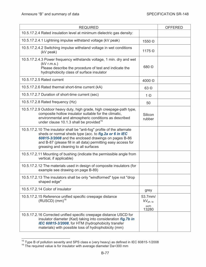
Annexure “B” and summary of data SPECIFICATION SR-148
B-77
REQUIRED OFFERED
10.5.17.2.4 Rated insulation level at minimum dielectric gas density:
10.5.17.2.4.1 Lightning impulse withstand voltage (kV peak) 1550 ©
10.5.17.2.4.2 Switching impulse withstand voltage in wet conditions (kV peak) 1175 ©
10.5.17.2.4.3 Power frequency withstands voltage, 1 min. dry and wet (kV r.m.s.) Please describe the procedure of test and indicate the hydrophobicity class of surface insulator
680 ©
10.5.17.2.5 Rated current 4000 ©
10.5.17.2.6 Rated thermal short-time current (kA) 63 ©
10.5.17.2.7 Duration of short-time current (sec) 1 ©
10.5.17.2.8 Rated frequency (Hz) 50
10.5.17.2.9 Outdoor heavy duty, high grade, high creepage-path type, composite hollow insulator suitable for the climatic, environmental and atmospheric conditions as described under clause 10.1.3 shall be provided15
Silicon rubber
10.5.17.2.10 The insulator shall be "anti-fog" profile of the alternate sheds or normal sheds type (acc. to fig.2a or 6 in IEC 60815-3/2008 and the enclosed drawings on pages B-86 and B-87 (please fill in all data) permitting easy access for greasing and cleaning to all surfaces
10.5.17.2.11 Mounting of bushing (indicate the permissible angle from vertical, if applicable)
10.5.17.2.12 The materials used in design of composite insulators (for example see drawing on page B-89)
10.5.17.2.13 The insulators shall be only "windformed" type not "drop shaped edge"
10.5.17.2.14 Color of insulator grey
10.5.17.2.15 Reference unified specific creepage distance (RUSCD) (mm)16
53.7mm/kVph. to
earth
13280
10.5.17.2.16 Corrected unified specific creepage distance USCD for insulator diameter (Kad) taking into consideration fig.7b in IEC 60815-3/2008, for HTM (hydrophobicity transfer materials) with possible loss of hydrophobicity (mm)
15
Type B of pollution severity and SPS class e (very heavy) as defined in IEC 60815-1/2008 16
The required value is for insulator with average diameter Da<300 mm
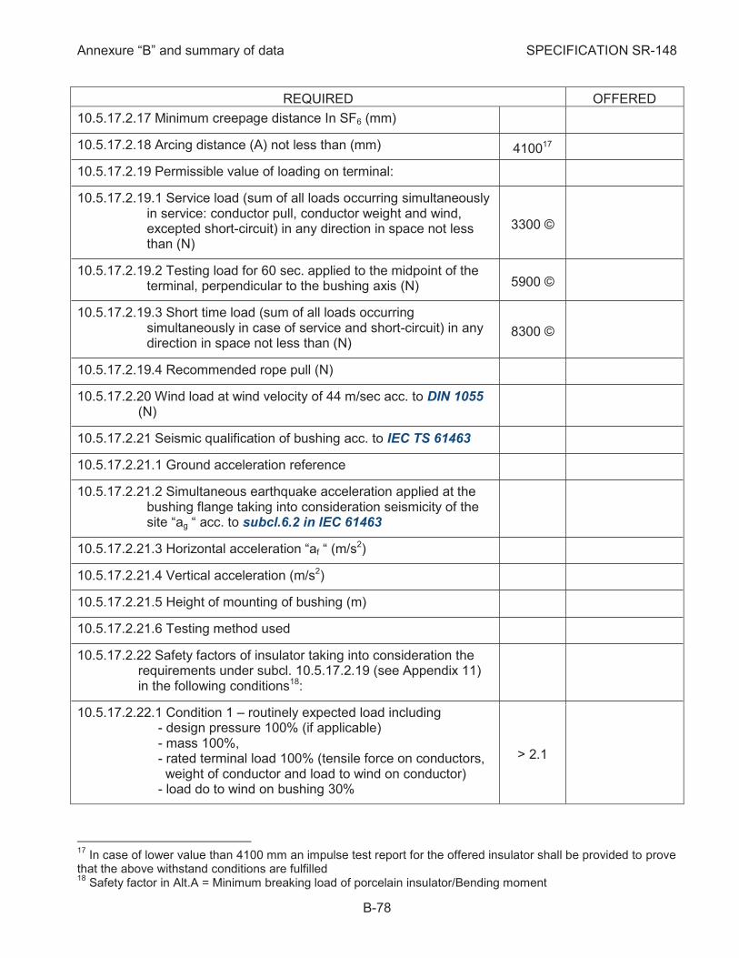
Annexure “B” and summary of data SPECIFICATION SR-148
B-78
REQUIRED OFFERED
10.5.17.2.17 Minimum creepage distance In SF6 (mm)
10.5.17.2.18 Arcing distance (A) not less than (mm) 410017
10.5.17.2.19 Permissible value of loading on terminal:
10.5.17.2.19.1 Service load (sum of all loads occurring simultaneously in service: conductor pull, conductor weight and wind, excepted short-circuit) in any direction in space not less than (N)
3300 ©
10.5.17.2.19.2 Testing load for 60 sec. applied to the midpoint of the terminal, perpendicular to the bushing axis (N) 5900 ©
10.5.17.2.19.3 Short time load (sum of all loads occurring simultaneously in case of service and short-circuit) in any direction in space not less than (N)
8300 ©
10.5.17.2.19.4 Recommended rope pull (N)
10.5.17.2.20 Wind load at wind velocity of 44 m/sec acc. to DIN 1055 (N)
10.5.17.2.21 Seismic qualification of bushing acc. to IEC TS 61463
10.5.17.2.21.1 Ground acceleration reference
10.5.17.2.21.2 Simultaneous earthquake acceleration applied at the bushing flange taking into consideration seismicity of the site “ag “ acc. to subcl.6.2 in IEC 61463
10.5.17.2.21.3 Horizontal acceleration “af “ (m/s2)
10.5.17.2.21.4 Vertical acceleration (m/s2)
10.5.17.2.21.5 Height of mounting of bushing (m)
10.5.17.2.21.6 Testing method used
10.5.17.2.22 Safety factors of insulator taking into consideration the requirements under subcl. 10.5.17.2.19 (see Appendix 11) in the following conditions18:
10.5.17.2.22.1 Condition 1 – routinely expected load including - design pressure 100% (if applicable) - mass 100%, - rated terminal load 100% (tensile force on conductors, weight of conductor and load to wind on conductor) - load do to wind on bushing 30%
> 2.1
17
In case of lower value than 4100 mm an impulse test report for the offered insulator shall be provided to prove that the above withstand conditions are fulfilled 18
Safety factor in Alt.A = Minimum breaking load of porcelain insulator/Bending moment
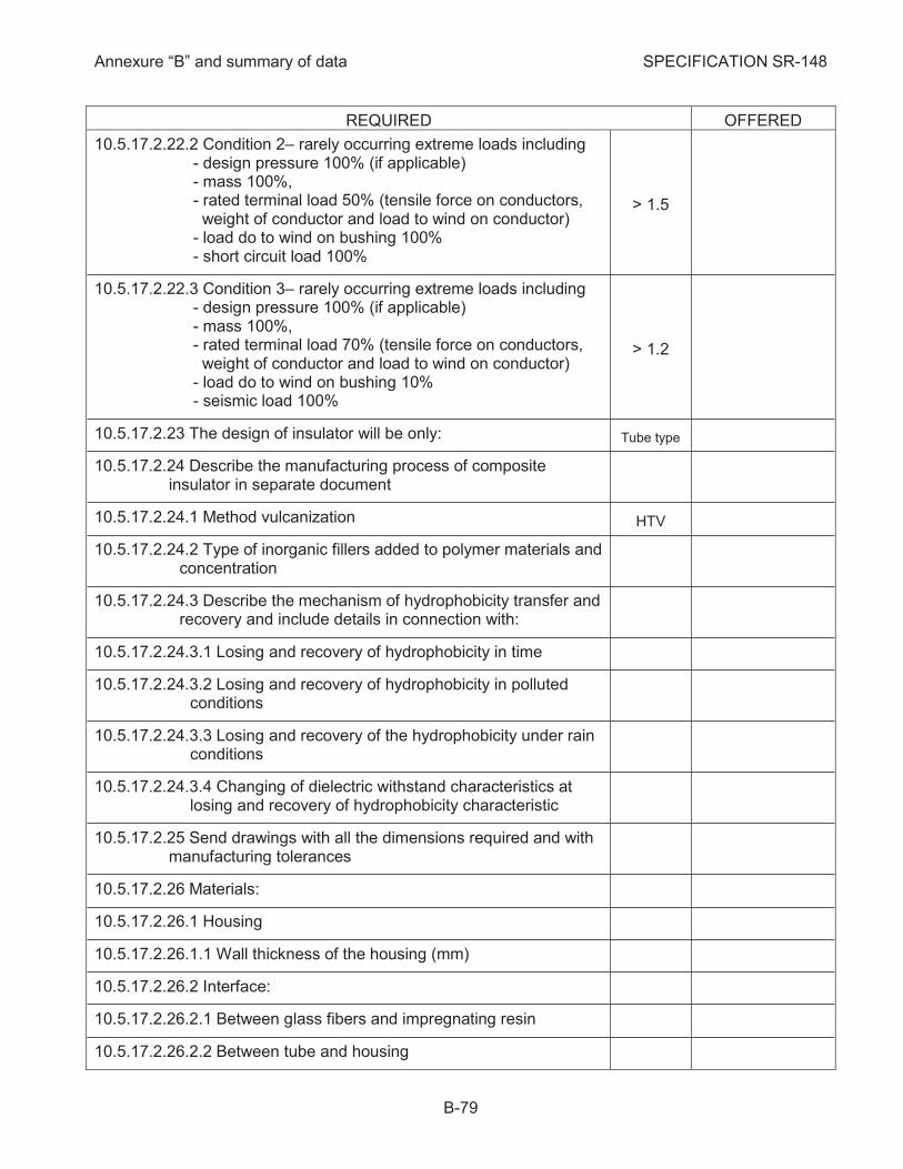
Annexure “B” and summary of data SPECIFICATION SR-148
B-79
REQUIRED OFFERED
10.5.17.2.22.2 Condition 2– rarely occurring extreme loads including - design pressure 100% (if applicable) - mass 100%, - rated terminal load 50% (tensile force on conductors, weight of conductor and load to wind on conductor) - load do to wind on bushing 100% - short circuit load 100%
> 1.5
10.5.17.2.22.3 Condition 3– rarely occurring extreme loads including - design pressure 100% (if applicable) - mass 100%, - rated terminal load 70% (tensile force on conductors, weight of conductor and load to wind on conductor) - load do to wind on bushing 10% - seismic load 100%
> 1.2
10.5.17.2.23 The design of insulator will be only: Tube type
10.5.17.2.24 Describe the manufacturing process of composite insulator in separate document
10.5.17.2.24.1 Method vulcanization HTV
10.5.17.2.24.2 Type of inorganic fillers added to polymer materials and concentration
10.5.17.2.24.3 Describe the mechanism of hydrophobicity transfer and recovery and include details in connection with:
10.5.17.2.24.3.1 Losing and recovery of hydrophobicity in time
10.5.17.2.24.3.2 Losing and recovery of hydrophobicity in polluted conditions
10.5.17.2.24.3.3 Losing and recovery of the hydrophobicity under rain conditions
10.5.17.2.24.3.4 Changing of dielectric withstand characteristics at losing and recovery of hydrophobicity characteristic
10.5.17.2.25 Send drawings with all the dimensions required and with manufacturing tolerances
10.5.17.2.26 Materials:
10.5.17.2.26.1 Housing
10.5.17.2.26.1.1 Wall thickness of the housing (mm)
10.5.17.2.26.2 Interface:
10.5.17.2.26.2.1 Between glass fibers and impregnating resin
10.5.17.2.26.2.2 Between tube and housing

Annexure “B” and summary of data SPECIFICATION SR-148
B-80
REQUIRED OFFERED
10.5.17.2.26.2.3 Between various parts of the housing: between sheds and sheath
10.5.17.2.26.2.4 Between housing, tube and end fittings
10.5.17.2.26.3 Tube
10.5.17.2.26.4 End fitting
10.5.17.2.27 Indicate if electrode or capacitive foil and film condenser body are provided
10.5.17.2.28 Indicate if corona ring is necessary
10.5.17.2.29 Specify the surface hydrophobicity level of the hollow insulator material at the time of installation acc. to IEC 62073/2003 Indicate the measurement method and send test report. Indicate also the difference between hydrophobicity level of upper and lower shed surface, if applicable. Send also a graph including hydrophobicity distribution along the length of insulator.
10.5.17.2.30 Specify the loss of hydrophobicity of sheds versus time, the loss of hydrophobicity in polluted zone and ability to recover hydrophobicity after loss
10.5.17.2.31 Electric field level near end fittings (kV/cm)
10.5.17.2.32 Recommended method to detect on site the defective insulators (send technical description)
10.5.17.2.33 Limits of temperature inside the tube (highest/lowest) (0C/0C)
10.5.17.2.34 Tube characteristics:
10.5.17.2.34.1 External diameter (mm)
10.5.17.2.34.2 Internal diameter (mm)
10.5.17.2.34.3 Wall thickness (mm)
10.5.17.2.34.4 Specified Mechanical load (SML) at room temperature (N) > 17500
10.5.17.2.34.4.1 Deflection under bending load of SML (tube in irreversible plastic phase) (mm)
10.5.17.2.34.4.2 Residual deflection after release of the above load (mm)
10.5.17.2.34.5 Maximum Mechanical Load (MML) (N) > 7500
10.5.17.2.34.5.1 Deflection under bending load (MML) (mm)

Annexure “B” and summary of data SPECIFICATION SR-148
B-81
REQUIRED OFFERED
10.5.17.2.34.5.2 Deflection under bending load 1.5xMML (tube in elastic phase) (mm)
10.5.17.2.34.5.3 Residual deflection after release of the above load (mm)
10.5.17.2.34.6 Specified internal pressure (SIP) (MPa)
10.5.17.2.34.7 Maximum service pressure (MSP) (MPa)
10.5.17.2.34.8 Maximum permissible axial stress (MPa)
10.5.17.2.34.9 Maximum residual strain after bending load:
10.5.17.2.34.9.1 MML load (µm/m)
10.5.17.2.34.9.2 Damage limit load (µm/m)
10.5.17.2.34.9.3 SML load (µm/m)
10.5.17.2.34.10 Maximal tube residual deflection under bending load:
10.5.17.2.34.10.1 MML load (mm)
10.5.17.2.34.10.2 Damage limit load (mm)
10.5.17.2.34.10.3 SML load (mm)
10.5.17.2.34.11 Other method to determine the onset of deterioration (if applicable)
10.5.17.2.35 Indicate if the influence of solar radiation is included in calculation of MSP
10.5.17.2.36 Indicate method of attaching the metal end-fitting to the tube. Describe also the checking methods
10.5.17.2.37 Indicate the sealing system for composite hollow insulator
10.5.17.2.38 Indicate if decomposition product resulted from interactions between interior surface of the tube and gaseous or liquid insulation materials
10.5.17.2.39 Required minimum air clearance "phase to phase/phase to earth" (m/m)
10.5.17.2.40 Weights:
10.5.17.2.41 Type, sample and routine tests reports shall be supplied acc. to IEC 61462 and IEC 60137-08
Requirements for SF6/Cable Connections for GIS 10.5.18
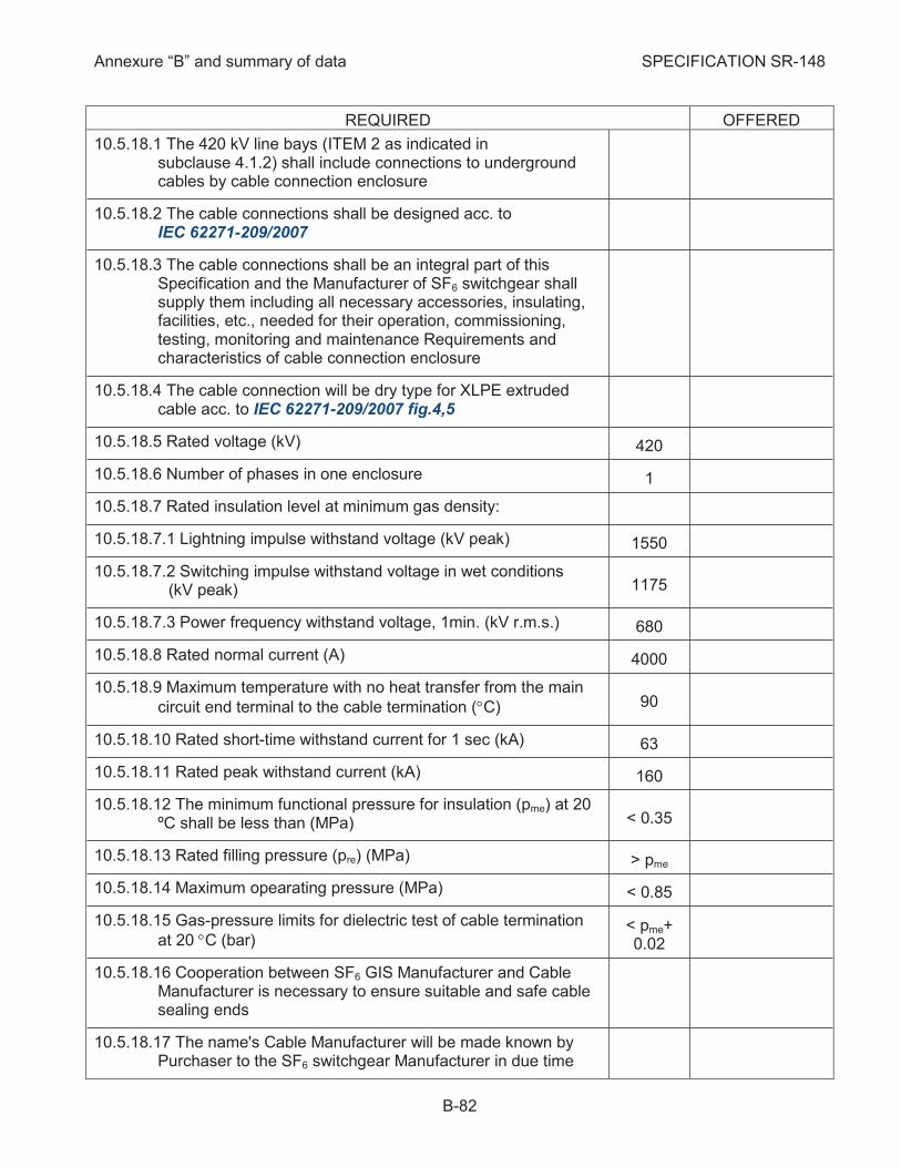
Annexure “B” and summary of data SPECIFICATION SR-148
B-82
REQUIRED OFFERED
10.5.18.1 The 420 kV line bays (ITEM 2 as indicated in subclause 4.1.2) shall include connections to underground cables by cable connection enclosure
10.5.18.2 The cable connections shall be designed acc. to IEC 62271-209/2007
10.5.18.3 The cable connections shall be an integral part of this Specification and the Manufacturer of SF6 switchgear shall supply them including all necessary accessories, insulating, facilities, etc., needed for their operation, commissioning, testing, monitoring and maintenance Requirements and characteristics of cable connection enclosure
10.5.18.4 The cable connection will be dry type for XLPE extruded cable acc. to IEC 62271-209/2007 fig.4,5
10.5.18.5 Rated voltage (kV) 420
10.5.18.6 Number of phases in one enclosure 1
10.5.18.7 Rated insulation level at minimum gas density:
10.5.18.7.1 Lightning impulse withstand voltage (kV peak) 1550
10.5.18.7.2 Switching impulse withstand voltage in wet conditions (kV peak) 1175
10.5.18.7.3 Power frequency withstand voltage, 1min. (kV r.m.s.) 680
10.5.18.8 Rated normal current (A) 4000
10.5.18.9 Maximum temperature with no heat transfer from the main
circuit end terminal to the cable termination (°C) 90
10.5.18.10 Rated short-time withstand current for 1 sec (kA) 63
10.5.18.11 Rated peak withstand current (kA) 160
10.5.18.12 The minimum functional pressure for insulation (pme) at 20 ºC shall be less than (MPa) < 0.35
10.5.18.13 Rated filling pressure (pre) (MPa) > pme
10.5.18.14 Maximum opearating pressure (MPa) < 0.85
10.5.18.15 Gas-pressure limits for dielectric test of cable termination
at 20 °C (bar) < pme+ 0.02
10.5.18.16 Cooperation between SF6 GIS Manufacturer and Cable Manufacturer is necessary to ensure suitable and safe cable sealing ends
10.5.18.17 The name's Cable Manufacturer will be made known by Purchaser to the SF6 switchgear Manufacturer in due time
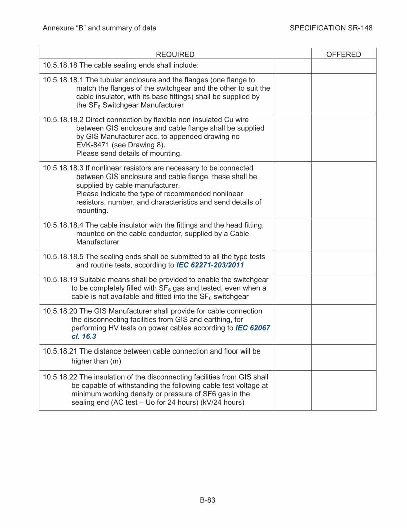
Annexure “B” and summary of data SPECIFICATION SR-148
B-83
REQUIRED OFFERED
10.5.18.18 The cable sealing ends shall include:
10.5.18.18.1 The tubular enclosure and the flanges (one flange to match the flanges of the switchgear and the other to suit the cable insulator, with its base fittings) shall be supplied by the SF6 Switchgear Manufacturer
10.5.18.18.2 Direct connection by flexible non insulated Cu wire between GIS enclosure and cable flange shall be supplied by GIS Manufacturer acc. to appended drawing no EVK-8471 (see Drawing 8). Please send details of mounting.
10.5.18.18.3 If nonlinear resistors are necessary to be connected between GIS enclosure and cable flange, these shall be supplied by cable manufacturer. Please indicate the type of recommended nonlinear resistors, number, and characteristics and send details of mounting.
10.5.18.18.4 The cable insulator with the fittings and the head fitting, mounted on the cable conductor, supplied by a Cable Manufacturer
10.5.18.18.5 The sealing ends shall be submitted to all the type tests and routine tests, according to IEC 62271-203/2011
10.5.18.19 Suitable means shall be provided to enable the switchgear to be completely filled with SF6 gas and tested, even when a cable is not available and fitted into the SF6 switchgear
10.5.18.20 The GIS Manufacturer shall provide for cable connection the disconnecting facilities from GIS and earthing, for performing HV tests on power cables according to IEC 62067 cl. 16.3
10.5.18.21 The distance between cable connection and floor will be
higher than (m)
10.5.18.22 The insulation of the disconnecting facilities from GIS shall be capable of withstanding the following cable test voltage at minimum working density or pressure of SF6 gas in the sealing end (AC test – Uo for 24 hours) (kV/24 hours)
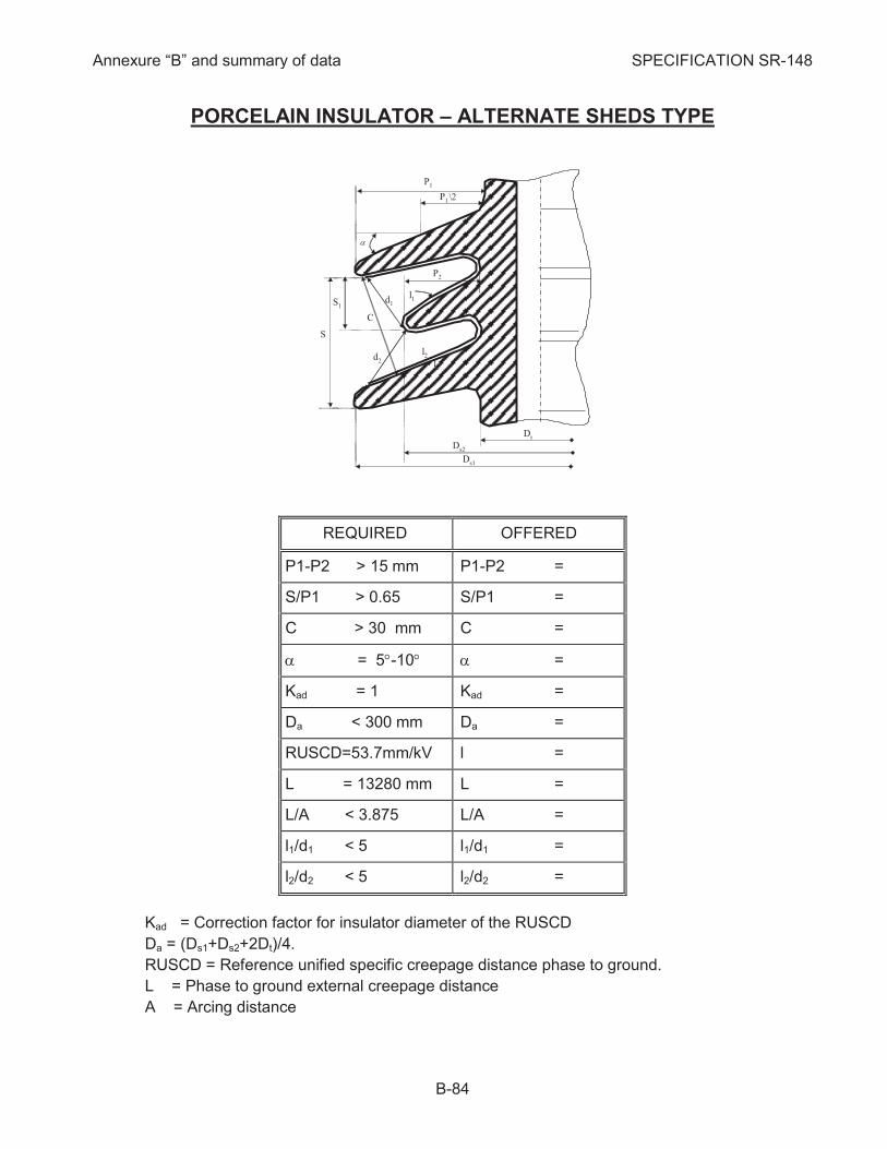
Annexure “B” and summary of data SPECIFICATION SR-148
B-84
PORCELAIN INSULATOR – ALTERNATE SHEDS TYPE
REQUIRED OFFERED
P1-P2 > 15 mm P1-P2 =
S/P1 > 0.65 S/P1 =
C > 30 mm C =
a = 5°-10° a =
Kad = 1 Kad =
Da < 300 mm Da =
RUSCD=53.7mm/kV l =
L = 13280 mm L =
L/A < 3.875 L/A =
l1/d1 < 5 l1/d1 =
l2/d2 < 5 l2/d2 =
Kad = Correction factor for insulator diameter of the RUSCD
Da = (Ds1+Ds2+2Dt)/4.
RUSCD = Reference unified specific creepage distance phase to ground.
L = Phase to ground external creepage distance
A = Arcing distance
P1
P2
P1
S1
l1
d2
S
d1
l2
Dt
l2
Ds2
Ds1
a
\2
C
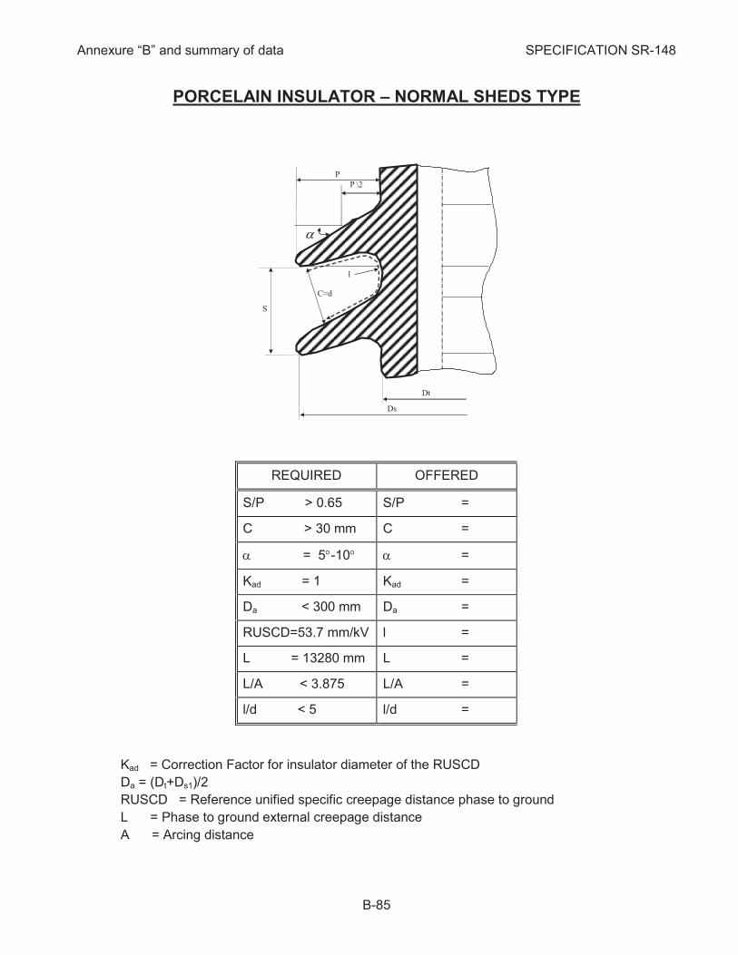
Annexure “B” and summary of data SPECIFICATION SR-148
B-85
PORCELAIN INSULATOR – NORMAL SHEDS TYPE
REQUIRED OFFERED
S/P > 0.65 S/P =
C > 30 mm C =
a = 5°-10° a =
Kad = 1 Kad =
Da < 300 mm Da =
RUSCD=53.7 mm/kV l =
L = 13280 mm L =
L/A < 3.875 L/A =
l/d < 5 l/d =
Kad = Correction Factor for insulator diameter of the RUSCD
Da = (Dt+Ds1)/2
RUSCD = Reference unified specific creepage distance phase to ground
L = Phase to ground external creepage distance
A = Arcing distance
S
C=d
P
l
P
Dt
Ds
a
\2

Annexure “B” and summary of data SPECIFICATION SR-148
B-86
COMPOSITE INSULATOR – ALTERNATE SHEDS TYPE
REQUIRED OFFERED
P1-P2 > 15 mm P1-P2 =
S/P1 > 0.65 S/P1 =
C > 40 mm C =
a = 5°-10° a =
Kad = 1 Kad =
Da < 300 mm Da =
RUSCD = 53.7 mm/kV l =
L = 13280 mm L =
L/A < 4.7 L/A =
l1/d1 < 4.5 l1/d1 =
l2/d2 < 4.5 l2/d2 =
Kad = Correction factor of the RUSCD for insulator diameter
Da = (Ds1+Ds2+2Dt)/4
RUSCD = Reference unified specific creepage distance phase to ground.
L = Phase to ground external creepage distance
A = Arcing distance
P1
P2
P1
S1
l1
d2
S
d1
l2
Dt
l2
Ds2
Ds1
a
\2
C
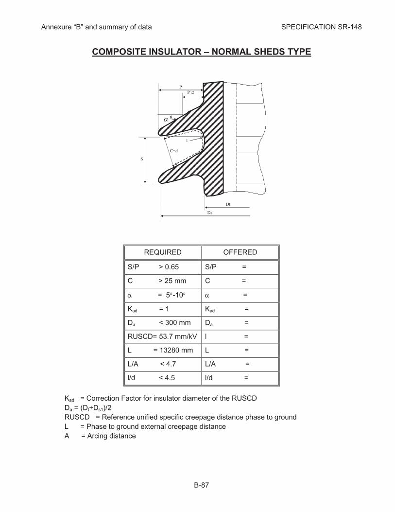
Annexure “B” and summary of data SPECIFICATION SR-148
B-87
COMPOSITE INSULATOR – NORMAL SHEDS TYPE
REQUIRED OFFERED
S/P > 0.65 S/P =
C > 25 mm C =
a = 5°-10° a =
Kad = 1 Kad =
Da < 300 mm Da =
RUSCD= 53.7 mm/kV l =
L = 13280 mm L =
L/A < 4.7 L/A =
l/d < 4.5 l/d =
Kad = Correction Factor for insulator diameter of the RUSCD
Da = (Dt+Ds1)/2
RUSCD = Reference unified specific creepage distance phase to ground
L = Phase to ground external creepage distance
A = Arcing distance
S
C=d
P
l
P
Dt
Ds
a
\2

Annexure “B” and summary of data SPECIFICATION SR-148
B-88
PORCELAIN INSULATOR
NO. MATERIALS DETAILS
1 BONDING MATERIAL
2 PRIMER
3 FINAL PROTECTIVE PAINT
4 FLANGE MATERIAL
5 OTHER MATERIALS
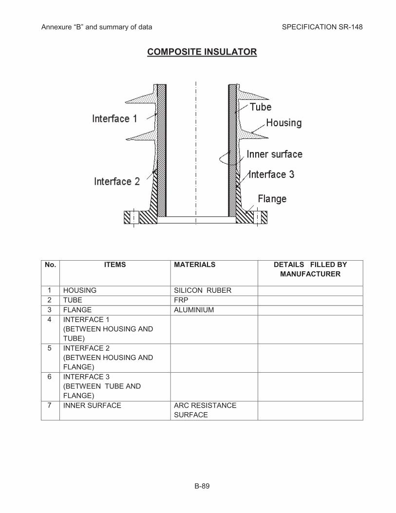
Annexure “B” and summary of data SPECIFICATION SR-148
B-89
COMPOSITE INSULATOR
DETAILS FILLED BY
MANUFACTURER
MATERIALS ITEMS No.
SILICON RUBER HOUSING 1
FRP TUBE 2
ALUMINIUM FLANGE 3
INTERFACE 1
(BETWEEN HOUSING AND
TUBE)
4
INTERFACE 2
(BETWEEN HOUSING AND
FLANGE)
5
INTERFACE 3
(BETWEEN TUBE AND
FLANGE)
6
ARC RESISTANCE
SURFACE
INNER SURFACE 7
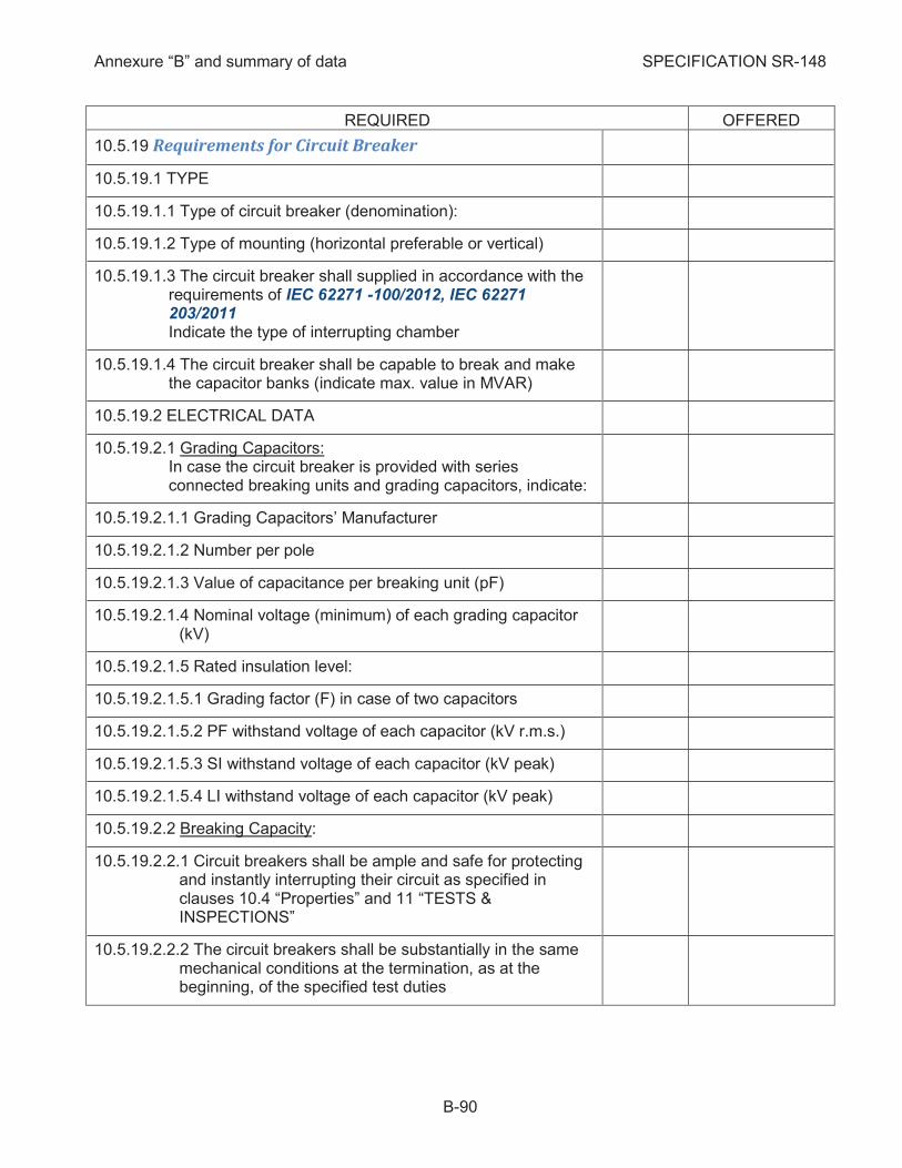
Annexure “B” and summary of data SPECIFICATION SR-148
B-90
REQUIRED OFFERED
Requirements for Circuit Breaker 10.5.19
10.5.19.1 TYPE
10.5.19.1.1 Type of circuit breaker (denomination):
10.5.19.1.2 Type of mounting (horizontal preferable or vertical)
10.5.19.1.3 The circuit breaker shall supplied in accordance with the requirements of IEC 62271 -100/2012, IEC 62271 203/2011
Indicate the type of interrupting chamber
10.5.19.1.4 The circuit breaker shall be capable to break and make the capacitor banks (indicate max. value in MVAR)
10.5.19.2 ELECTRICAL DATA
10.5.19.2.1 Grading Capacitors: In case the circuit breaker is provided with series connected breaking units and grading capacitors, indicate:
10.5.19.2.1.1 Grading Capacitors’ Manufacturer
10.5.19.2.1.2 Number per pole
10.5.19.2.1.3 Value of capacitance per breaking unit (pF)
10.5.19.2.1.4 Nominal voltage (minimum) of each grading capacitor (kV)
10.5.19.2.1.5 Rated insulation level:
10.5.19.2.1.5.1 Grading factor (F) in case of two capacitors
10.5.19.2.1.5.2 PF withstand voltage of each capacitor (kV r.m.s.)
10.5.19.2.1.5.3 SI withstand voltage of each capacitor (kV peak)
10.5.19.2.1.5.4 LI withstand voltage of each capacitor (kV peak)
10.5.19.2.2 Breaking Capacity:
10.5.19.2.2.1 Circuit breakers shall be ample and safe for protecting and instantly interrupting their circuit as specified in clauses 10.4 “Properties” and 11 “TESTS & INSPECTIONS”
10.5.19.2.2.2 The circuit breakers shall be substantially in the same mechanical conditions at the termination, as at the beginning, of the specified test duties

Annexure “B” and summary of data SPECIFICATION SR-148
B-91
REQUIRED OFFERED
10.5.19.2.2.3 Circuit breakers shall be capable for carrying rated voltage and their main current carrying parts shall be at the termination of the specified tests substantially in the same condition as at the beginning
10.5.19.2.2.4 The breakers shall be restrike free for all operating duties except capacitive current breaking (see cl. 10.5.19.2.16). They shall be able to break any current up to the rated breaking current at any voltage up to maximum rated voltage
10.5.19.2.2.5 The breakers shall be type C2 (very low expected probability of restrike during capacitive current breaking). This restrike performance in service shall be demonstrated by specific type test.
10.5.19.2.2.6 The breakers shall be class M2 proved by mechanical endurance test consist of 10000 operating sequences without changing of the contacts
10.5.19.2.2.7 Number of series connected breaking units per pole
10.5.19.2.2.8 The circuit breaker shall have a monitoring system to ensure that all breaker poles are either open or closed
10.5.19.2.3 Auto-Reclosing: The breakers shall be supplied suitable for single and three-phase rapid auto-reclosing duty, acc. to IEC 62271-100/2012 cl.4.104
10.5.19.2.4 Rated voltage Ur (kV) 420
10.5.19.2.5 Rated insulation level acc. to IEC 62271-1/2011 cl.4.2 and IEC 62271-100/2012 Ó
10.5.19.2.5.1 Rated lightning impulse withstand voltage 1.2/50 msec full wave, both polarities “to earth/across open contacts” Up (kV peak)
1425/1425 (+240)
10.5.19.2.5.2 10.5.19.2.5.2 Switching impulse withstand voltage test,
250/2500 msec both polarities “to earth/across open contacts” Up (kV peak)
1050/900 (+345)
10.5.19.2.5.3 Rated short duration power frequency withstands voltage 1 min. “to earth/across open contacts” Ud (kV r.m.s.)
680/815
10.5.19.2.6 Rated normal current Ir19
Indicate the over-current capability of CB (if applicable)
10.5.19.2.6.1 Line and autotransformer bays (A) 4000 ©
19
Acc. to one line diagrams no. AR-4475/7
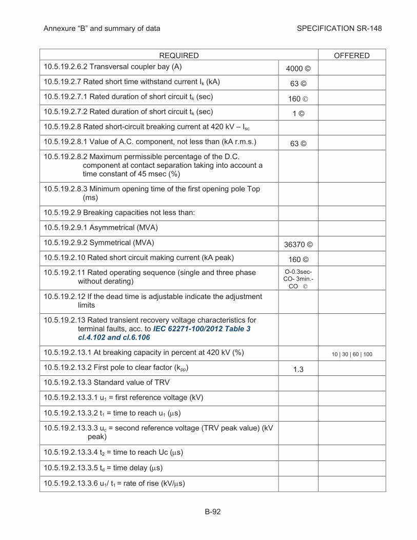
Annexure “B” and summary of data SPECIFICATION SR-148
B-92
REQUIRED OFFERED
10.5.19.2.6.2 Transversal coupler bay (A) 4000 ©
10.5.19.2.7 Rated short time withstand current Ik (kA) 63 ©
10.5.19.2.7.1 Rated duration of short circuit tk (sec) 160 Ó
10.5.19.2.7.2 Rated duration of short circuit tk (sec) 1 ©
10.5.19.2.8 Rated short-circuit breaking current at 420 kV – Isc
10.5.19.2.8.1 Value of A.C. component, not less than (kA r.m.s.) 63 ©
10.5.19.2.8.2 Maximum permissible percentage of the D.C. component at contact separation taking into account a time constant of 45 msec (%)
10.5.19.2.8.3 Minimum opening time of the first opening pole Top (ms)
10.5.19.2.9 Breaking capacities not less than:
10.5.19.2.9.1 Asymmetrical (MVA)
10.5.19.2.9.2 Symmetrical (MVA) 36370 ©
10.5.19.2.10 Rated short circuit making current (kA peak) 160 ©
10.5.19.2.11 Rated operating sequence (single and three phase without derating)
O-0.3sec-CO- 3min.-
CO Ó
10.5.19.2.12 If the dead time is adjustable indicate the adjustment limits
10.5.19.2.13 Rated transient recovery voltage characteristics for terminal faults, acc. to IEC 62271-100/2012 Table 3 cl.4.102 and cl.6.106
10.5.19.2.13.1 At breaking capacity in percent at 420 kV (%) 10 | 30 | 60 | 100
10.5.19.2.13.2 First pole to clear factor (kpp) 1.3
10.5.19.2.13.3 Standard value of TRV
10.5.19.2.13.3.1 u1 = first reference voltage (kV)
10.5.19.2.13.3.2 t1 = time to reach u1 (ms)
10.5.19.2.13.3.3 uc = second reference voltage (TRV peak value) (kV peak)
10.5.19.2.13.3.4 t2 = time to reach Uc (ms)
10.5.19.2.13.3.5 td = time delay (ms)
10.5.19.2.13.3.6 u1/ t1 = rate of rise (kV/ms)
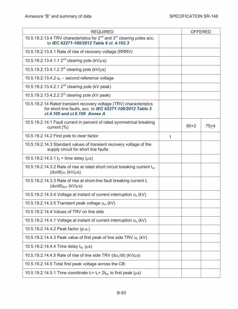
Annexure “B” and summary of data SPECIFICATION SR-148
B-93
REQUIRED OFFERED
10.5.19.2.13.4 TRV characteristics for 2nd and 3rd clearing poles acc. to IEC 62271-100/2012 Table 6 cl. 4.102.3
10.5.19.2.13.4.1 Rate of rise of recovery voltage (RRRV)
10.5.19.2.13.4.1.1 2nd clearing pole (kV/ms)
10.5.19.2.13.4.1.2 3rd clearing pole (kV/ms)
10.5.19.2.13.4.2 uc – second reference voltage
10.5.19.2.13.4.2.1 2nd clearing pole (kV peak)
10.5.19.2.13.4.2.2 3rd clearing pole (kV peak)
10.5.19.2.14 Rated transient recovery voltage (TRV) characteristics for short-line faults, acc. to IEC 62271-100/2012 Table 3 cl.4.105 and cl.6.109 Annex A
10.5.19.2.14.1 Fault current in percent of rated symmetrical breaking current (%) 90+2 75+4
10.5.19.2.14.2 First pole to clear factor 1
10.5.19.2.14.3 Standard values of transient recovery voltage of the supply circuit for short line faults
10.5.19.2.14.3.1 td = time delay (ms)
10.5.19.2.14.3.2 Rate of rise at rated short circuit breaking current Isc
(du/dt)TF (kV/ms)
10.5.19.2.14.3.3 Rate of rise at short-line fault breaking current IL
(du/dt)SLF (kV/ms)
10.5.19.2.14.3.4 Voltage at instant of current interruption ux (kV)
10.5.19.2.14.3.5 Transient peak voltage um (kV)
10.5.19.2.14.4 Values of TRV on line side
10.5.19.2.14.4.1 Voltage at instant of current interruption uo (kV)
10.5.19.2.14.4.2 Peak factor (p.u.)
10.5.19.2.14.4.3 Peak value of first peak of line side TRV uL (kV)
10.5.19.2.14.4.4 Time delay tdL (ms)
10.5.19.2.14.4.5 Rate of rise of line side TRV (duL/dt) (kV/ms)
10.5.19.2.14.5 Total first peak voltage across the CB:
10.5.19.2.14.5.1 Time coordinate tT= tL+ 2tDL to first peak (ms)

Annexure “B” and summary of data SPECIFICATION SR-148
B-94
REQUIRED OFFERED
10.5.19.2.14.5.2 Source side voltage contribution uS to TRV at tT (kV)
10.5.19.2.14.5.3 First peak voltage uT = uL* + uS* (kV)
10.5.19.2.15 Rated out-of-phase making and breaking current acc. to IEC 62271-100/2012 cl.4.102 Table 3 cl.4.106 and cl.6.110
10.5.19.2.15.1 Value of out-of-phase breaking current Iop (kA) 15.75
10.5.19.2.15.2 Value of out-of-phase making current Iop (kA) 22.05
10.5.19.2.15.3 Symmetrical breaking current in percent of the assigned out of phase breaking capacity (% Iop) acc. to IEC 62271-100/2012 Table 26
Test Duty
OP1 OP2
10.5.19.2.15.4 D. C component of the breaking current shall be less than of the A.C. component (%) 20
10.5.19.2.15.5 Transient recovery voltage characteristics for out-of-phase breaking, acc. to IEC 62271-100/2012 cl.4.102 Table 3
10.5.19.2.15.5.1 First pole to clear factor 2
10.5.19.2.15.5.2 u1 = first reference voltage (kV)
10.5.19.2.15.5.3 t1 = time to reach u1 (ms)
10.5.19.2.15.5.4 uC = TRV peak value (kV)
10.5.19.2.15.5.5 t2 = time to reach uC (ms)
10.5.19.2.15.5.6 td = time delay (ms)
10.5.19.2.15.5.7 u1/ t1 = rate of rise (kV/ms)
10.5.19.2.15.6 Out-of-phase power frequency recovery voltage (kV) 2Un/Ö3= 485
10.5.19.2.16 Rated capacitive switching currents acc. to IEC 62271-100/2012 cl.4.107 Table 9 IEEE C37 06 table 14
10.5.19.2.16.1 Class of CB in connection to restrike performance C2
10.5.19.2.16.2 Rated line charging breaking current (A) 500
10.5.19.2.16.3 Rated cable charging breaking current (A) 1000
10.5.19.2.16.4 Rated single capacitor bank breaking current (A) 1000
10.5.19.2.16.5 Rated single capacitor bank inrush making current (current/frequency) (kA peak/Hz) 7.6/627
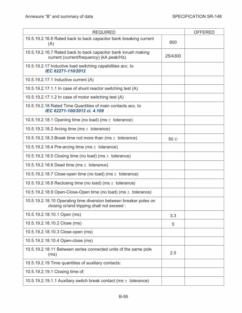
Annexure “B” and summary of data SPECIFICATION SR-148
B-95
REQUIRED OFFERED
10.5.19.2.16.6 Rated back to back capacitor bank breaking current (A) 800
10.5.19.2.16.7 Rated back to back capacitor bank inrush making current (current/frequency) (kA peak/Hz) 25/4300
10.5.19.2.17 Inductive load switching capabilities acc. to IEC 62271-110/2012
10.5.19.2.17.1 Inductive current (A)
10.5.19.2.17.1.1 In case of shunt reactor switching test (A)
10.5.19.2.17.1.2 In case of motor switching test (A)
10.5.19.2.18 Rated Time Quantities of main contacts acc. to IEC 62271-100/2012 cl. 4.109
10.5.19.2.18.1 Opening time (no load) (ms ± tolerance)
10.5.19.2.18.2 Arcing time (ms ± tolerance)
10.5.19.2.18.3 Break time not more than (ms ± tolerance) 50 Ó
10.5.19.2.18.4 Pre-arcing time (ms ± tolerance)
10.5.19.2.18.5 Closing time (no load) (ms ± tolerance)
10.5.19.2.18.6 Dead time (ms ± tolerance)
10.5.19.2.18.7 Close-open time (no load) (ms ± tolerance)
10.5.19.2.18.8 Reclosing time (no load) (ms ± tolerance)
10.5.19.2.18.9 Open-Close-Open time (no load) (ms ± tolerance)
10.5.19.2.18.10 Operating time diversion between breaker poles on closing or/and tripping shall not exceed :
10.5.19.2.18.10.1 Open (ms) 3.3
10.5.19.2.18.10.2 Close (ms) 5
10.5.19.2.18.10.3 Close-open (ms)
10.5.19.2.18.10.4 Open-close (ms)
10.5.19.2.18.11 Between series connected units of the same pole (ms) 2.5
10.5.19.2.19 Time quantities of auxiliary contacts:
10.5.19.2.19.1 Closing time of:
10.5.19.2.19.1.1 Auxiliary switch break contact (ms ± tolerance)
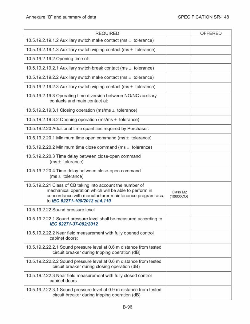
Annexure “B” and summary of data SPECIFICATION SR-148
B-96
REQUIRED OFFERED
10.5.19.2.19.1.2 Auxiliary switch make contact (ms ± tolerance)
10.5.19.2.19.1.3 Auxiliary switch wiping contact (ms ± tolerance)
10.5.19.2.19.2 Opening time of:
10.5.19.2.19.2.1 Auxiliary switch break contact (ms ± tolerance)
10.5.19.2.19.2.2 Auxiliary switch make contact (ms ± tolerance)
10.5.19.2.19.2.3 Auxiliary switch wiping contact (ms ± tolerance)
10.5.19.2.19.3 Operating time diversion between NO/NC auxiliary contacts and main contact at:
10.5.19.2.19.3.1 Closing operation (ms/ms ± tolerance)
10.5.19.2.19.3.2 Opening operation (ms/ms ± tolerance)
10.5.19.2.20 Additional time quantities required by Purchaser:
10.5.19.2.20.1 Minimum time open command (ms ± tolerance)
10.5.19.2.20.2 Minimum time close command (ms ± tolerance)
10.5.19.2.20.3 Time delay between close-open command
(ms ± tolerance)
10.5.19.2.20.4 Time delay between close-open command
(ms ± tolerance)
10.5.19.2.21 Class of CB taking into account the number of mechanical operation which will be able to perform in concordance with manufacturer maintenance program acc. to IEC 62271-100/2012 cl.4.110
Class M2 (10000CO)
10.5.19.2.22 Sound pressure level
10.5.19.2.22.1 Sound pressure level shall be measured according to IEC 62271-37-082/2012
10.5.19.2.22.2 Near field measurement with fully opened control cabinet doors:
10.5.19.2.22.2.1 Sound pressure level at 0.6 m distance from tested circuit breaker during tripping operation (dB)
10.5.19.2.22.2.2 Sound pressure level at 0.6 m distance from tested circuit breaker during closing operation (dB)
10.5.19.2.22.3 Near field measurement with fully closed control cabinet doors
10.5.19.2.22.3.1 Sound pressure level at 0.9 m distance from tested circuit breaker during tripping operation (dB)
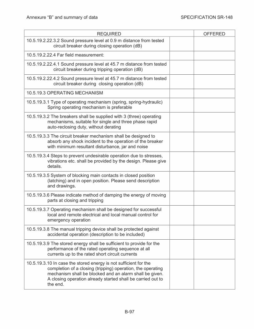
Annexure “B” and summary of data SPECIFICATION SR-148
B-97
REQUIRED OFFERED
10.5.19.2.22.3.2 Sound pressure level at 0.9 m distance from tested circuit breaker during closing operation (dB)
10.5.19.2.22.4 Far field measurement:
10.5.19.2.22.4.1 Sound pressure level at 45.7 m distance from tested circuit breaker during tripping operation (dB)
10.5.19.2.22.4.2 Sound pressure level at 45.7 m distance from tested circuit breaker during closing operation (dB)
10.5.19.3 OPERATING MECHANISM
10.5.19.3.1 Type of operating mechanism (spring, spring-hydraulic) Spring operating mechanism is preferable
10.5.19.3.2 The breakers shall be supplied with 3 (three) operating mechanisms, suitable for single and three phase rapid auto-reclosing duty, without derating
10.5.19.3.3 The circuit breaker mechanism shall be designed to absorb any shock incident to the operation of the breaker with minimum resultant disturbance, jar and noise
10.5.19.3.4 Steps to prevent undesirable operation due to stresses, vibrations etc. shall be provided by the design. Please give details.
10.5.19.3.5 System of blocking main contacts in closed position (latching) and in open position. Please send description and drawings.
10.5.19.3.6 Please indicate method of damping the energy of moving parts at closing and tripping
10.5.19.3.7 Operating mechanism shall be designed for successful local and remote electrical and local manual control for emergency operation
10.5.19.3.8 The manual tripping device shall be protected against accidental operation (description to be included)
10.5.19.3.9 The stored energy shall be sufficient to provide for the performance of the rated operating sequence at all currents up to the rated short circuit currents
10.5.19.3.10 In case the stored energy is not sufficient for the completion of a closing (tripping) operation, the operating mechanism shall be blocked and an alarm shall be given. A closing operation already started shall be carried out to the end.
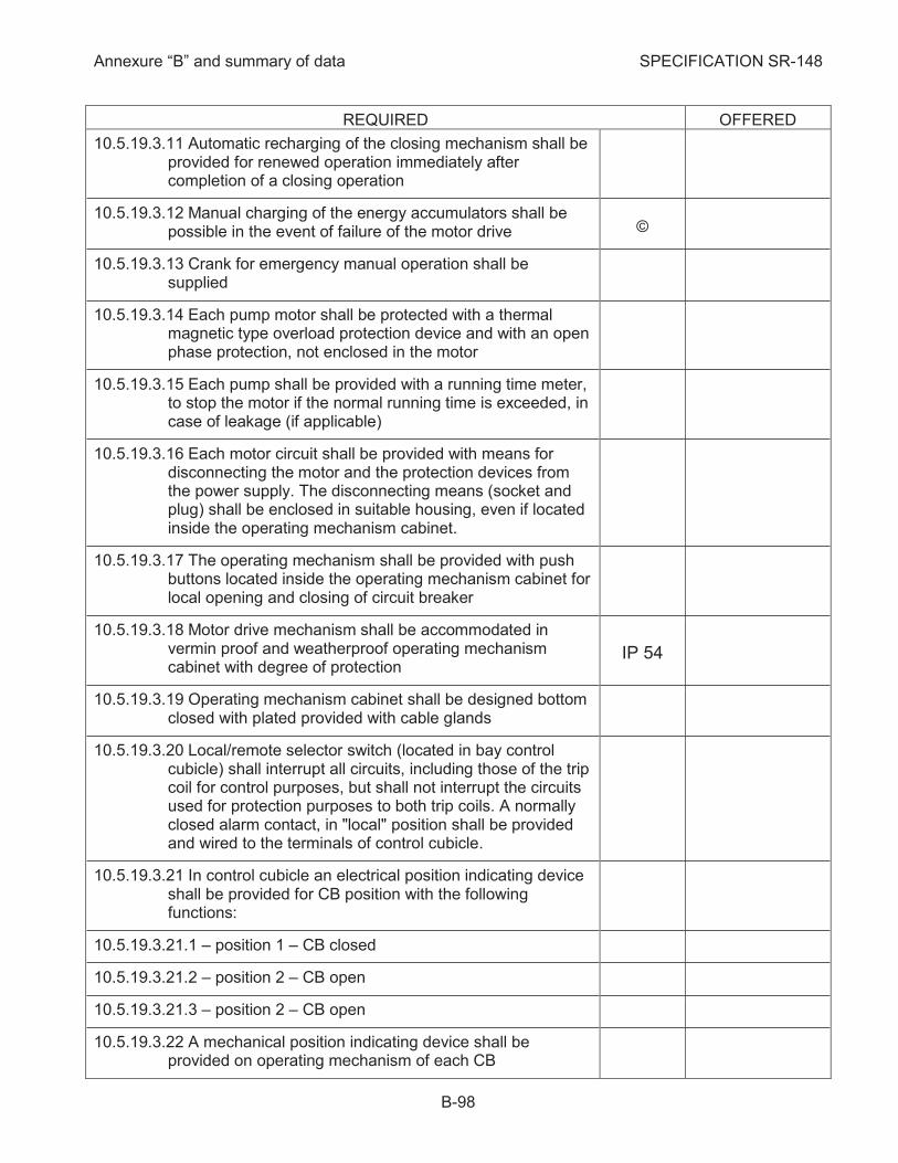
Annexure “B” and summary of data SPECIFICATION SR-148
B-98
REQUIRED OFFERED
10.5.19.3.11 Automatic recharging of the closing mechanism shall be provided for renewed operation immediately after completion of a closing operation
10.5.19.3.12 Manual charging of the energy accumulators shall be possible in the event of failure of the motor drive ©
10.5.19.3.13 Crank for emergency manual operation shall be supplied
10.5.19.3.14 Each pump motor shall be protected with a thermal magnetic type overload protection device and with an open phase protection, not enclosed in the motor
10.5.19.3.15 Each pump shall be provided with a running time meter, to stop the motor if the normal running time is exceeded, in case of leakage (if applicable)
10.5.19.3.16 Each motor circuit shall be provided with means for disconnecting the motor and the protection devices from the power supply. The disconnecting means (socket and plug) shall be enclosed in suitable housing, even if located inside the operating mechanism cabinet.
10.5.19.3.17 The operating mechanism shall be provided with push buttons located inside the operating mechanism cabinet for local opening and closing of circuit breaker
10.5.19.3.18 Motor drive mechanism shall be accommodated in vermin proof and weatherproof operating mechanism cabinet with degree of protection
IP 54
10.5.19.3.19 Operating mechanism cabinet shall be designed bottom closed with plated provided with cable glands
10.5.19.3.20 Local/remote selector switch (located in bay control cubicle) shall interrupt all circuits, including those of the trip coil for control purposes, but shall not interrupt the circuits used for protection purposes to both trip coils. A normally closed alarm contact, in "local" position shall be provided and wired to the terminals of control cubicle.
10.5.19.3.21 In control cubicle an electrical position indicating device shall be provided for CB position with the following functions:
10.5.19.3.21.1 – position 1 – CB closed
10.5.19.3.21.2 – position 2 – CB open
10.5.19.3.21.3 – position 2 – CB open
10.5.19.3.22 A mechanical position indicating device shall be provided on operating mechanism of each CB
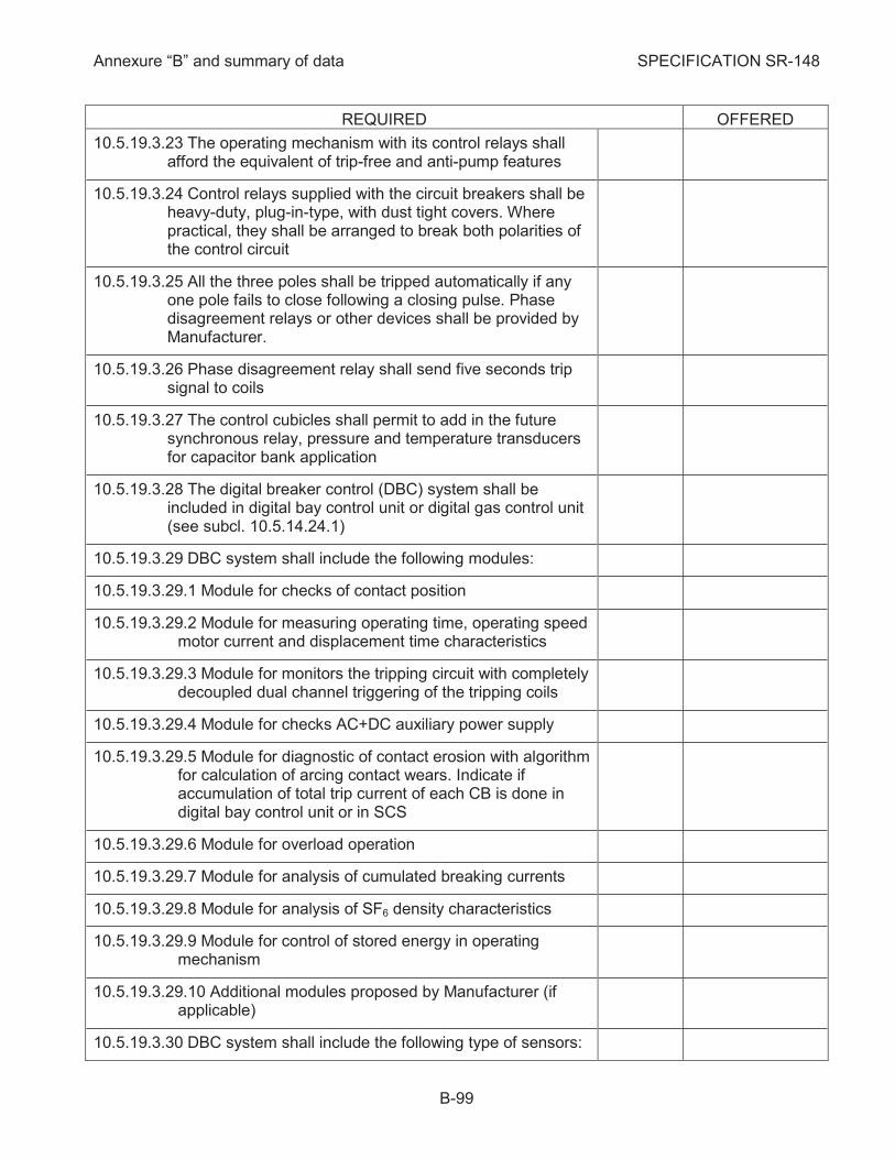
Annexure “B” and summary of data SPECIFICATION SR-148
B-99
REQUIRED OFFERED
10.5.19.3.23 The operating mechanism with its control relays shall afford the equivalent of trip-free and anti-pump features
10.5.19.3.24 Control relays supplied with the circuit breakers shall be heavy-duty, plug-in-type, with dust tight covers. Where practical, they shall be arranged to break both polarities of the control circuit
10.5.19.3.25 All the three poles shall be tripped automatically if any one pole fails to close following a closing pulse. Phase disagreement relays or other devices shall be provided by Manufacturer.
10.5.19.3.26 Phase disagreement relay shall send five seconds trip signal to coils
10.5.19.3.27 The control cubicles shall permit to add in the future synchronous relay, pressure and temperature transducers for capacitor bank application
10.5.19.3.28 The digital breaker control (DBC) system shall be included in digital bay control unit or digital gas control unit (see subcl. 10.5.14.24.1)
10.5.19.3.29 DBC system shall include the following modules:
10.5.19.3.29.1 Module for checks of contact position
10.5.19.3.29.2 Module for measuring operating time, operating speed motor current and displacement time characteristics
10.5.19.3.29.3 Module for monitors the tripping circuit with completely decoupled dual channel triggering of the tripping coils
10.5.19.3.29.4 Module for checks AC+DC auxiliary power supply
10.5.19.3.29.5 Module for diagnostic of contact erosion with algorithm for calculation of arcing contact wears. Indicate if accumulation of total trip current of each CB is done in digital bay control unit or in SCS
10.5.19.3.29.6 Module for overload operation
10.5.19.3.29.7 Module for analysis of cumulated breaking currents
10.5.19.3.29.8 Module for analysis of SF6 density characteristics
10.5.19.3.29.9 Module for control of stored energy in operating mechanism
10.5.19.3.29.10 Additional modules proposed by Manufacturer (if applicable)
10.5.19.3.30 DBC system shall include the following type of sensors:

Annexure “B” and summary of data SPECIFICATION SR-148
B-100
REQUIRED OFFERED
10.5.19.3.30.1 Travel sensor
10.5.19.3.30.2 Current-watch sensor
10.5.19.3.30.3 Voltage sensor
10.5.19.3.30.4 Temperature sensor
10.5.19.3.30.5 Gas density sensor
10.5.19.3.30.6 Coil-watch sensor
10.5.19.3.30.7 Spring energy sensor (if applicable)
10.5.19.3.30.8 Other sensors proposed by Manufacturer (if applicable)
10.5.19.3.31 Indicate if the above sensors or other components for analog values measuring and processing are required for mounting in control cubicle
10.5.19.3.32 Power supply voltage:
10.5.19.3.32.1 Control circuit (V-D.C.) 220 (+10%) (-15%)
10.5.19.3.32.2 Alarm circuit (V-D.C.) 60 (+10%) (-15%)
10.5.19.3.33 The operating mechanism shall be capable of closing and opening the circuit breaker for any value of supply voltage between 85% and 110% of the rated value
10.5.19.3.34 The closing coil shall operate correctly between 85% and 110% of the rated supply voltage of the closing device
10.5.19.3.35 The opening coil shall operate correctly between 70% and 110% of the rated supply voltage of the opening device
10.5.19.3.36 Number of closing coils per breaker.(per phase) 1
10.5.19.3.36.1 Maximum power rating per closing coil at 220 V D.C. (W/phase)
10.5.19.3.36.2 Permissible duration of total current by closing circuit (s)
10.5.19.3.36.3 Resistance of closing coil (W)
10.5.19.3.37 Number of tripping coils per breaker (per phase) 2
10.5.19.3.37.1 Maximum power rating per tripping coil at 220V DC (W/phase)
10.5.19.3.37.2 Rated trip current at 220 V-DC (A/phase)

Annexure “B” and summary of data SPECIFICATION SR-148
B-101
REQUIRED OFFERED
10.5.19.3.37.3 Tripping peak current when tripping circuits are energized at 220 V-DC (A/phase)
10.5.19.3.37.4 Permissible duration of total current by tripping circuit (s)
10.5.19.3.37.5 Resistance of tripping coil (W)
10.5.19.3.37.6 Each tripping coil shall be mounted on separated armature of magnet
10.5.19.3.38 Maximum cable resistance at 220 V-DC of the tripping
circuit for which trip coil operation is assured (W/phase)
10.5.19.3.39 Facilities shall be provided to enable travel and timing measurements to be carried out after the switchgear has been filled with SF6 gas. The test connections shall be possible without opening of any gas section
10.5.19.3.40 The routine test of each CB shall include contact movement diagram (contact displacement as against time) for main contact and auxiliary switches. The Manufacturer shall indicate method of plotting, list of apparatus used and information about possible modification of the curves
10.5.19.3.41 The Contractor shall propose a type of travel-time recorder (with the possibility to obtain travel-time and acceleration curves of the contacts) to be included in his scope of supply. Indicate type.
10.5.19.3.42 Minimum SF6 gas pressure or density for which circuit breakers operation is allowed without mechanical damages (bar or g/l)
10.5.19.3.43 The following alarms shall be provided as a minimum: (indicate corresponding values)
10.5.19.3.43.1 Abnormal density of SF6 gas system (low density, minimum breaking density /pressure, minimum dielectric density)
10.5.19.3.43.2 Abnormal pressure of the operating mechanism at
20 C°
10.5.19.3.43.2.1 Low/high pressure with time delay (bar/bar)
10.5.19.3.43.2.2 Minimum auto-reclosing pressure (bar)
10.5.19.3.43.2.3 Minimum closing pressure (bar)
10.5.19.3.43.2.4 Minimum tripping pressure if applicable (bar)
10.5.19.3.43.3 Under voltage for direct current control circuits
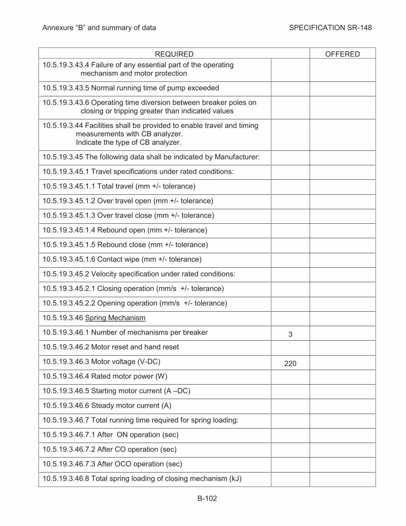
Annexure “B” and summary of data SPECIFICATION SR-148
B-102
REQUIRED OFFERED
10.5.19.3.43.4 Failure of any essential part of the operating mechanism and motor protection
10.5.19.3.43.5 Normal running time of pump exceeded
10.5.19.3.43.6 Operating time diversion between breaker poles on closing or tripping greater than indicated values
10.5.19.3.44 Facilities shall be provided to enable travel and timing measurements with CB analyzer. Indicate the type of CB analyzer.
10.5.19.3.45 The following data shall be indicated by Manufacturer:
10.5.19.3.45.1 Travel specifications under rated conditions:
10.5.19.3.45.1.1 Total travel (mm +/- tolerance)
10.5.19.3.45.1.2 Over travel open (mm +/- tolerance)
10.5.19.3.45.1.3 Over travel close (mm +/- tolerance)
10.5.19.3.45.1.4 Rebound open (mm +/- tolerance)
10.5.19.3.45.1.5 Rebound close (mm +/- tolerance)
10.5.19.3.45.1.6 Contact wipe (mm +/- tolerance)
10.5.19.3.45.2 Velocity specification under rated conditions:
10.5.19.3.45.2.1 Closing operation (mm/s +/- tolerance)
10.5.19.3.45.2.2 Opening operation (mm/s +/- tolerance)
10.5.19.3.46 Spring Mechanism
10.5.19.3.46.1 Number of mechanisms per breaker 3
10.5.19.3.46.2 Motor reset and hand reset
10.5.19.3.46.3 Motor voltage (V-DC) 220
10.5.19.3.46.4 Rated motor power (W)
10.5.19.3.46.5 Starting motor current (A –DC)
10.5.19.3.46.6 Steady motor current (A)
10.5.19.3.46.7 Total running time required for spring loading:
10.5.19.3.46.7.1 After ON operation (sec)
10.5.19.3.46.7.2 After CO operation (sec)
10.5.19.3.46.7.3 After OCO operation (sec)
10.5.19.3.46.8 Total spring loading of closing mechanism (kJ)

Annexure “B” and summary of data SPECIFICATION SR-148
B-103
REQUIRED OFFERED
10.5.19.3.46.9 Number of turns per closing operation
10.5.19.3.46.10 Spring mechanisms shall be provided with electrical and mechanical interlocks against undesired operation resulting from a mechanical fault
10.5.19.3.46.11 For hand reset the direction of motion of the handle shall be marked
10.5.19.3.46.12 Actuating force required for manually charging (N) <250
10.5.19.3.47 Spring Hydraulic Mechanism
10.5.19.3.47.1 Number of mechanisms per breaker 3
10.5.19.3.47.2 Spring-hydraulic mechanism shall be complete with pump, accumulator, necessary controls, piping, valves and wiring
10.5.19.3.47.3 Operating oil pressure shall be maintained automatically and a pressure gauge shall be provided to give indication of the pressure
10.5.19.3.47.4 Motor voltage (V-DC) 220
10.5.19.3.47.5 Rated motor power (W)
10.5.19.3.47.6 Rated motor power (W)
10.5.19.3.47.7 Starting motor current /elapsed time until steady current (A/msec)
10.5.19.3.47.8 Steady motor current (A)
10.5.19.3.47.9 Delivery rate (m3/h)
10.5.19.3.47.10 Total running time required for spring loading:
10.5.19.3.47.10.1 After 1 ON operation (sec)
10.5.19.3.47.10.2 After CO operation (sec)
10.5.19.3.47.10.3 After OCO operation (sec)
10.5.19.3.47.11 Stored operations
10.5.19.3.47.12 Spring-hydraulic mechanisms shall be provided with electrical and mechanical interlocks against undesired operation resulting from a mechanical fault
10.5.19.3.47.13 Blocking shall apply on all three phases, even if the pressure is low in only one or two phase mechanism(s)
10.5.19.3.47.14 Material of:
10.5.19.3.47.14.1 High and low hydraulic piping
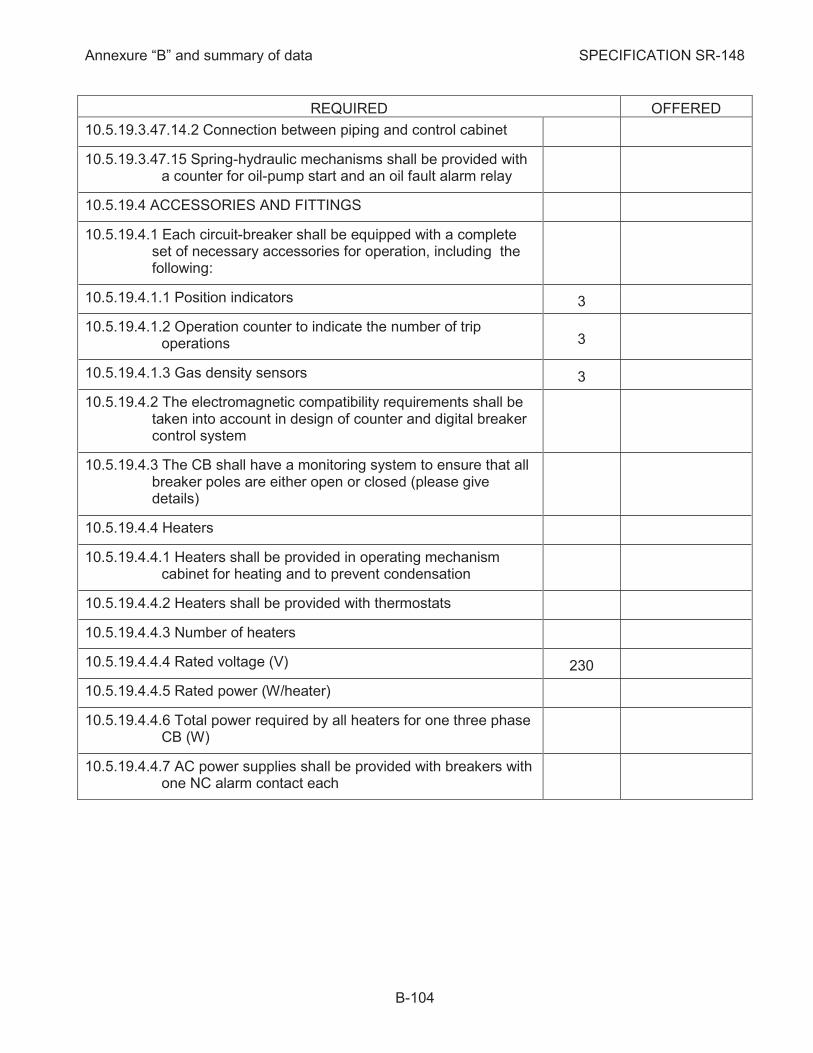
Annexure “B” and summary of data SPECIFICATION SR-148
B-104
REQUIRED OFFERED
10.5.19.3.47.14.2 Connection between piping and control cabinet
10.5.19.3.47.15 Spring-hydraulic mechanisms shall be provided with a counter for oil-pump start and an oil fault alarm relay
10.5.19.4 ACCESSORIES AND FITTINGS
10.5.19.4.1 Each circuit-breaker shall be equipped with a complete set of necessary accessories for operation, including the following:
10.5.19.4.1.1 Position indicators 3
10.5.19.4.1.2 Operation counter to indicate the number of trip operations 3
10.5.19.4.1.3 Gas density sensors 3
10.5.19.4.2 The electromagnetic compatibility requirements shall be taken into account in design of counter and digital breaker control system
10.5.19.4.3 The CB shall have a monitoring system to ensure that all breaker poles are either open or closed (please give details)
10.5.19.4.4 Heaters
10.5.19.4.4.1 Heaters shall be provided in operating mechanism cabinet for heating and to prevent condensation
10.5.19.4.4.2 Heaters shall be provided with thermostats
10.5.19.4.4.3 Number of heaters
10.5.19.4.4.4 Rated voltage (V) 230
10.5.19.4.4.5 Rated power (W/heater)
10.5.19.4.4.6 Total power required by all heaters for one three phase CB (W)
10.5.19.4.4.7 AC power supplies shall be provided with breakers with one NC alarm contact each

Annexure “B” and summary of data SPECIFICATION SR-148
B-105
Requirements for Disconnectors and Earthing Switches 10.5.20
10.5.20.1 Type and General Requirements:
10.5.20.1.1 Type of Disconnectors:
10.5.20.1.1.1 Item 1 – Disconnectors for line, autotransformer and coupler bays (Q1, Q2, Q9)
10.5.20.1.1.2 Item 2 – Disconnectors for busbar extension, hand operated (Q10, Q20)
10.5.20.1.1.3 Item 3 - The disconnectors Q9 can be offered as combined disconnectors with LSES Q52 (if applicable indicate type and send single line diagram modified accordingly)
10.5.20.1.2 Type of earthing switches:
10.5.20.1.2.1 High speed earthing switches (Q8, Q15, Q25)
10.5.20.1.2.2 Low speed earthing switches (Q51, Q52)
10.5.20.1.3 The Disconnectors and earthing switches shall be designed acc. to IEC 62271-102/2013 and IEC 62271-203/2011
10.5.20.1.4 All high and low speed earthing switches close to the circuit breakers and current transformers in all bays shall be designed as insulated earthing switches in order to enable an current injection test, without removing SF6 gas or other components
10.5.20.1.5 The insulated earthing switches shall be designed to have a insulation level of 2 kV and shall be able to carry an continuous current of 400 A
10.5.20.1.6 The earthing switches shall be provided with a indicating pointer linked directly to the operating shaft of the moving contact of each phase, in order to indicate the OPEN and CLOSE position of the earthing switches
©
10.5.20.1.7 In case that the requirement under subcl. 10.5.20.1.6 מעל cannot be fulfilled, windows shall be supplied for all low and high speed earthing switches
10.5.20.1.8 The inspection windows shall be so designed to assure an easy and reliable checking of contact position
10.5.20.1.9 Manufacturer shall submit with the proposal the relevant drawing for the above required pointer
10.5.20.1.10 Easy access to indicating position device and mechanical interlocks shall be provided
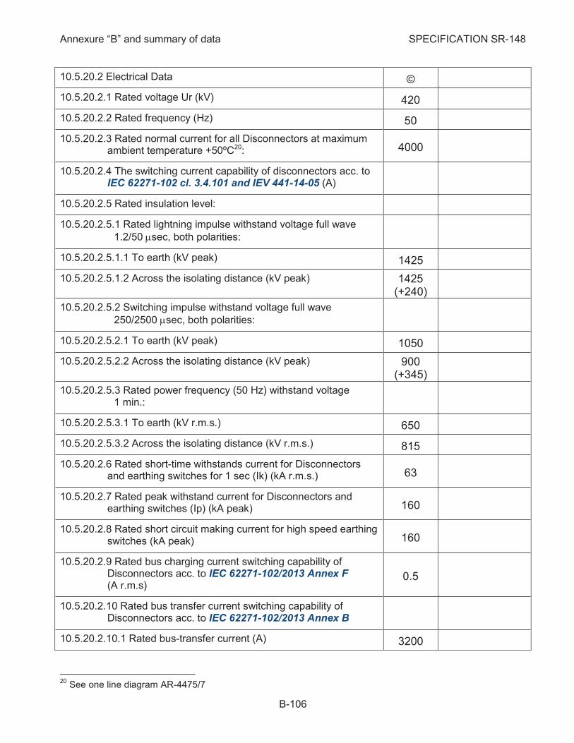
Annexure “B” and summary of data SPECIFICATION SR-148
B-106
10.5.20.2 Electrical Data ©
10.5.20.2.1 Rated voltage Ur (kV) 420
10.5.20.2.2 Rated frequency (Hz) 50
10.5.20.2.3 Rated normal current for all Disconnectors at maximum ambient temperature +50ºC20: 4000
10.5.20.2.4 The switching current capability of disconnectors acc. to IEC 62271-102 cl. 3.4.101 and IEV 441-14-05 (A)
10.5.20.2.5 Rated insulation level:
10.5.20.2.5.1 Rated lightning impulse withstand voltage full wave
1.2/50 msec, both polarities:
10.5.20.2.5.1.1 To earth (kV peak) 1425
10.5.20.2.5.1.2 Across the isolating distance (kV peak) 1425 (+240)
10.5.20.2.5.2 Switching impulse withstand voltage full wave
250/2500 msec, both polarities:
10.5.20.2.5.2.1 To earth (kV peak) 1050
10.5.20.2.5.2.2 Across the isolating distance (kV peak) 900 (+345)
10.5.20.2.5.3 Rated power frequency (50 Hz) withstand voltage 1 min.:
10.5.20.2.5.3.1 To earth (kV r.m.s.) 650
10.5.20.2.5.3.2 Across the isolating distance (kV r.m.s.) 815
10.5.20.2.6 Rated short-time withstands current for Disconnectors and earthing switches for 1 sec (Ik) (kA r.m.s.) 63
10.5.20.2.7 Rated peak withstand current for Disconnectors and earthing switches (Ip) (kA peak) 160
10.5.20.2.8 Rated short circuit making current for high speed earthing switches (kA peak) 160
10.5.20.2.9 Rated bus charging current switching capability of Disconnectors acc. to IEC 62271-102/2013 Annex F (A r.m.s)
0.5
10.5.20.2.10 Rated bus transfer current switching capability of Disconnectors acc. to IEC 62271-102/2013 Annex B
10.5.20.2.10.1 Rated bus-transfer current (A) 3200
20
See one line diagram AR-4475/7
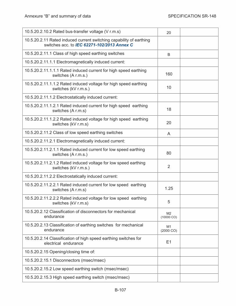
Annexure “B” and summary of data SPECIFICATION SR-148
B-107
10.5.20.2.10.2 Rated bus-transfer voltage (V r.m.s) 20
10.5.20.2.11 Rated induced current switching capability of earthing switches acc. to IEC 62271-102/2013 Annex C
10.5.20.2.11.1 Class of high speed earthing switches B
10.5.20.2.11.1.1 Electromagnetically induced current:
10.5.20.2.11.1.1.1 Rated induced current for high speed earthing switches (A r.m.s.) 160
10.5.20.2.11.1.1.2 Rated induced voltage for high speed earthing switches (kV r.m.s.) 10
10.5.20.2.11.1.2 Electrostatically induced current:
10.5.20.2.11.1.2.1 Rated induced current for high speed earthing switches (A r.m.s) 18
10.5.20.2.11.1.2.2 Rated induced voltage for high speed earthing switches (kV r.m.s) 20
10.5.20.2.11.2 Class of low speed earthing switches A
10.5.20.2.11.2.1 Electromagnetically induced current:
10.5.20.2.11.2.1.1 Rated induced current for low speed earthing switches (A r.m.s.) 80
10.5.20.2.11.2.1.2 Rated induced voltage for low speed earthing switches (kV r.m.s.) 2
10.5.20.2.11.2.2 Electrostatically induced current:
10.5.20.2.11.2.2.1 Rated induced current for low speed earthing switches (A r.m.s) 1.25
10.5.20.2.11.2.2.2 Rated induced voltage for low speed earthing switches (kV r.m.s) 5
10.5.20.2.12 Classification of disconnectors for mechanical endurance
M2 (10000 CO)
10.5.20.2.13 Classification of earthing switches for mechanical endurance
M1 (2000 CO)
10.5.20.2.14 Classification of high speed earthing switches for electrical endurance E1
10.5.20.2.15 Opening/closing time of:
10.5.20.2.15.1 Disconnectors (msec/msec)
10.5.20.2.15.2 Low speed earthing switch (msec/msec)
10.5.20.2.15.3 High speed earthing switch (msec/msec)
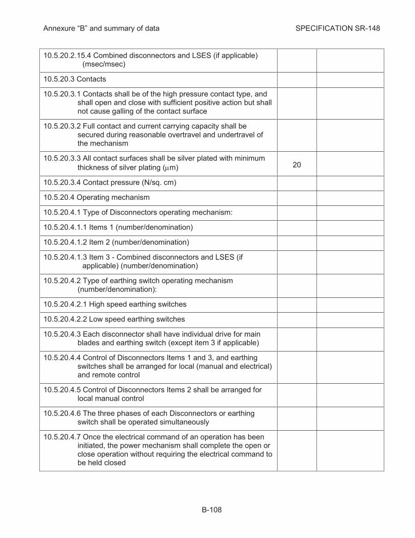
Annexure “B” and summary of data SPECIFICATION SR-148
B-108
10.5.20.2.15.4 Combined disconnectors and LSES (if applicable) (msec/msec)
10.5.20.3 Contacts
10.5.20.3.1 Contacts shall be of the high pressure contact type, and shall open and close with sufficient positive action but shall not cause galling of the contact surface
10.5.20.3.2 Full contact and current carrying capacity shall be secured during reasonable overtravel and undertravel of the mechanism
10.5.20.3.3 All contact surfaces shall be silver plated with minimum
thickness of silver plating (mm) 20
10.5.20.3.4 Contact pressure (N/sq. cm)
10.5.20.4 Operating mechanism
10.5.20.4.1 Type of Disconnectors operating mechanism:
10.5.20.4.1.1 Items 1 (number/denomination)
10.5.20.4.1.2 Item 2 (number/denomination)
10.5.20.4.1.3 Item 3 - Combined disconnectors and LSES (if applicable) (number/denomination)
10.5.20.4.2 Type of earthing switch operating mechanism (number/denomination):
10.5.20.4.2.1 High speed earthing switches
10.5.20.4.2.2 Low speed earthing switches
10.5.20.4.3 Each disconnector shall have individual drive for main blades and earthing switch (except item 3 if applicable)
10.5.20.4.4 Control of Disconnectors Items 1 and 3, and earthing switches shall be arranged for local (manual and electrical) and remote control
10.5.20.4.5 Control of Disconnectors Items 2 shall be arranged for local manual control
10.5.20.4.6 The three phases of each Disconnectors or earthing switch shall be operated simultaneously
10.5.20.4.7 Once the electrical command of an operation has been initiated, the power mechanism shall complete the open or close operation without requiring the electrical command to be held closed

Annexure “B” and summary of data SPECIFICATION SR-148
B-109
10.5.20.4.8 The Disconnectors and the earthing switches with single-phase operating mechanisms shall be provided with a time delayed discrepancy alarm to indicate that one or more phases failed to operate correctly
10.5.20.4.9 Local/remote selector switch shall be provided in the control cubicles for selecting the desired mode of operation of Disconnectors in each bay (see subcl. 10.5.14.18.3)
10.5.20.4.10 The operating mechanism shall be provided with push buttons located inside the operating mechanism cabinet for local opening and closing of isolator (see subcl. 10.5.14.18.5)
10.5.20.4.11 A local control key shall be provided in control cubicle for operation of each HS earthing switch (see subcl. 10.5.14.18.4)
10.5.20.4.12 Crank for emergency manual operation shall be supplied (except the HSES)
10.5.20.4.13 A normally closed alarm contact in "local" position shall be provided and wired to the terminals
10.5.20.4.14 In case of loss of auxiliary D.C. voltage for blocking purposes, the Disconnectors shall be blocked until unlocked with key to allow insertion of handle for manual operation
10.5.20.4.15 In control cubicle an electrical position indicating devices shall be provided for Disconnectors and earthing switch, with the following functions:
10.5.20.4.15.1 - Position 1 – closed
10.5.20.4.15.2 - Position 2 – open
10.5.20.4.15.3 - Position 3 - no voltage
10.5.20.4.16 Mechanical position indicating device shall also be provided on operating mechanism of Disconnectors and earthing switch
10.5.20.4.17 Manufacturer may also propose his own solution for a clear and reliable indication of the operating position of Disconnectors and earthing switches for approval by Purchaser
10.5.20.4.18 Control relays supplied with the disconnectors and the earthing switches shall be heavy-duty type, with dust tight covers. Where practical, they shall be arranged to break both polarities of the control circuit
10.5.20.4.19 Relay contacts shall be rated as indicated in subcl. 10.5.15.15 (Auxiliary switches)

Annexure “B” and summary of data SPECIFICATION SR-148
B-110
10.5.20.4.20 Maximum force and number of revolutions required for manual operation (N/no. of revolutions)
10.5.20.4.21 Each electrical motor for power operation shall be protected with a thermal-magnetic type overload protection device
10.5.20.4.22 Each motor circuit shall be provided with means for disconnecting the motor and the protection devices from the power supply (indicate type)
10.5.20.4.23 The disconnecting means shall be enclosed in suitable housing, even if located inside the operating mechanism cabinet
10.5.20.4.24 Rating of motor drive:
10.5.20.4.24.1 Rated power (kW)
10.5.20.4.24.2 Rated voltage (V. D.C.) 220 +10% -15%
10.5.20.4.24.3 Rated current (A)
10.5.20.4.24.4 Starting current / elapsed time until steady current (A/msec)
10.5.20.4.24.5 Total running time (sec)
10.5.20.4.25 Number of mechanisms per Disconnectors
10.5.20.4.26 Number of mechanisms per Earthing Switch
10.5.20.4.27 Number of mechanisms per combined Disconnector and Earthing Switch (if applicable)
10.5.20.4.28 The digital Disconnectors control and monitoring system shall be included in digital bay control unit (see 10.5.14.24.3) and shall include the following modules:
10.5.20.4.28.1 Module for recording motor current characteristics
10.5.20.4.28.2 Module for monitoring mechanism motion
10.5.20.4.28.3 Module for overload operation
10.5.20.4.28.4 . Module for analysis of SF6 gas density characteristics. Indicate the number of gas compartments which can be monitored.
10.5.20.4.28.5 Module for checks AC+DC auxiliary power supply
10.5.20.4.28.6 Additional modules proposed by Manufacturer (if applicable)
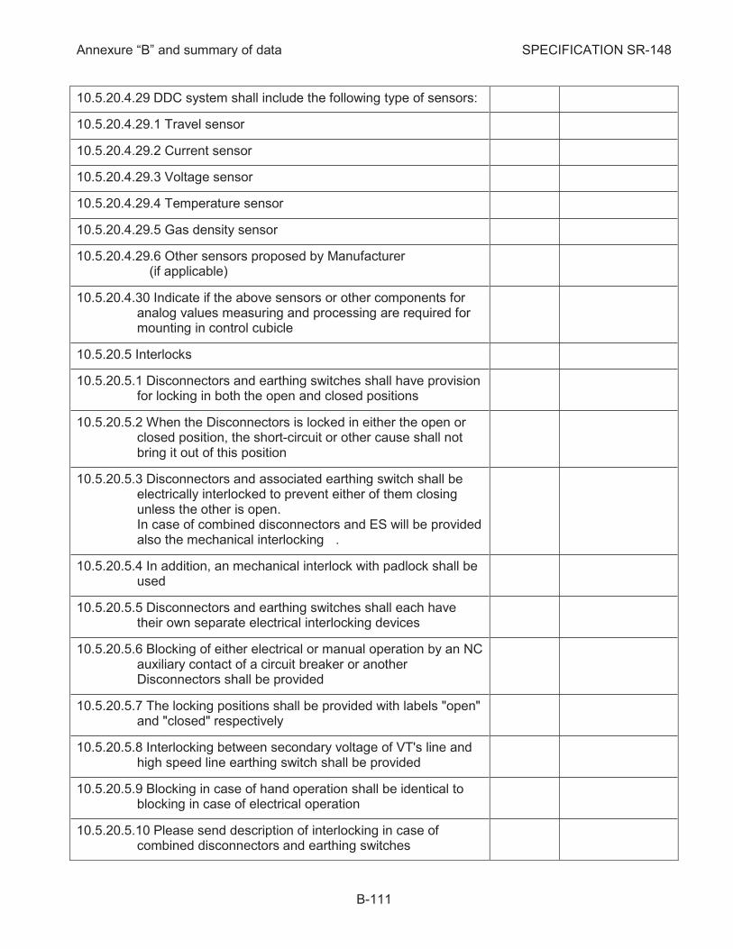
Annexure “B” and summary of data SPECIFICATION SR-148
B-111
10.5.20.4.29 DDC system shall include the following type of sensors:
10.5.20.4.29.1 Travel sensor
10.5.20.4.29.2 Current sensor
10.5.20.4.29.3 Voltage sensor
10.5.20.4.29.4 Temperature sensor
10.5.20.4.29.5 Gas density sensor
10.5.20.4.29.6 Other sensors proposed by Manufacturer (if applicable)
10.5.20.4.30 Indicate if the above sensors or other components for analog values measuring and processing are required for mounting in control cubicle
10.5.20.5 Interlocks
10.5.20.5.1 Disconnectors and earthing switches shall have provision for locking in both the open and closed positions
10.5.20.5.2 When the Disconnectors is locked in either the open or closed position, the short-circuit or other cause shall not bring it out of this position
10.5.20.5.3 Disconnectors and associated earthing switch shall be electrically interlocked to prevent either of them closing unless the other is open. In case of combined disconnectors and ES will be provided also the mechanical interlocking .
10.5.20.5.4 In addition, an mechanical interlock with padlock shall be used
10.5.20.5.5 Disconnectors and earthing switches shall each have their own separate electrical interlocking devices
10.5.20.5.6 Blocking of either electrical or manual operation by an NC auxiliary contact of a circuit breaker or another Disconnectors shall be provided
10.5.20.5.7 The locking positions shall be provided with labels "open" and "closed" respectively
10.5.20.5.8 Interlocking between secondary voltage of VT's line and high speed line earthing switch shall be provided
10.5.20.5.9 Blocking in case of hand operation shall be identical to blocking in case of electrical operation
10.5.20.5.10 Please send description of interlocking in case of combined disconnectors and earthing switches

Annexure “B” and summary of data SPECIFICATION SR-148
B-112
REQUIRED OFFERED
MEAS. CORE
PROT. CORE
MEAS. CORE
PROT. CORE
Requirements for Current 10.5.21
Transformers (T1)
10.5.21.1 TYPE
10.5.21.1.1 Types of current transformer (denomination)
10.5.21.1.2 The current transformer shall be supplied in accordance with:
IEC 61869-1/2007 IEC 61869-2/2012
10.5.21.1.3 Class of protective current transformer P
10.5.21.2 Electrical data cores no. 1,2,3,4 Ó Ó
10.5.21.2.1 Number of cores 1 3
10.5.21.2.2 Rated primary current Ipr (A) 2000-4000 2000-4000
10.5.21.2.3 Rated secondary current Isr (A) 1 1/1/1
10.5.21.2.4 Rated short time thermal current for 1sec Ith (kA r.m.s) 63
10.5.21.2.5 Rated dynamic current Idyn (kA peak) 160
10.5.21.2.6 Rated continuous thermal current Icth (1 x Ipr) (A) 2000-4000 2000-4000
10.5.21.2.7 Rated primary short circuit current Ipsc (kA r.m.s) 63
10.5.21.2.8 Extended current rating (%) 100 NA
10.5.21.2.9 Rated output burden Sr (VA) 15 20/40
10.5.21.2.10 Accuracy class 0.2S 5P
10.5.21.2.11 Instrument security factor FS 2.5-5 NA
10.5.21.2.12 Accuracy limit factor ALF NA 30
10.5.21.2.13 Current error at rated primary current (%) ± 0.2 ± 1
10.5.21.2.14 Phase displacement at rated primary current (min) ± 10 ± 60
10.5.21.2.15 Composite error εc (%) > 10 5
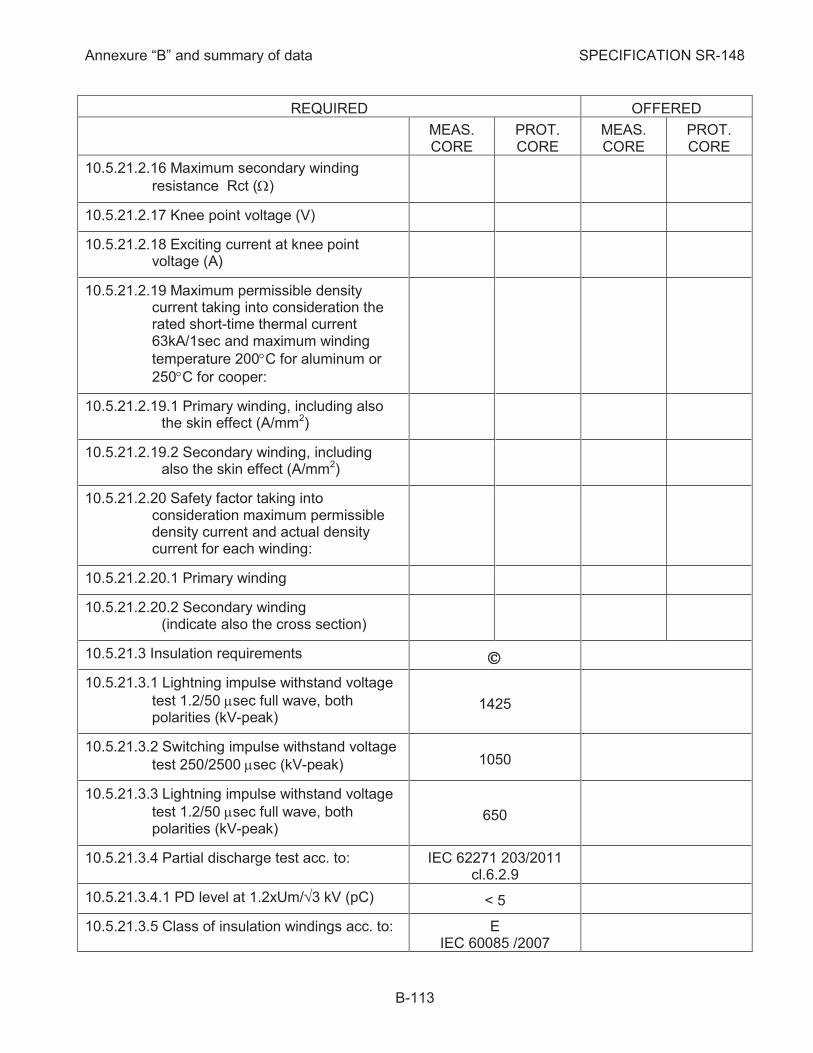
Annexure “B” and summary of data SPECIFICATION SR-148
B-113
REQUIRED OFFERED
MEAS. CORE
PROT. CORE
MEAS. CORE
PROT. CORE
10.5.21.2.16 Maximum secondary winding
resistance Rct (W)
10.5.21.2.17 Knee point voltage (V)
10.5.21.2.18 Exciting current at knee point voltage (A)
10.5.21.2.19 Maximum permissible density current taking into consideration the rated short-time thermal current 63kA/1sec and maximum winding
temperature 200°C for aluminum or
250°C for cooper:
10.5.21.2.19.1 Primary winding, including also the skin effect (A/mm2)
10.5.21.2.19.2 Secondary winding, including also the skin effect (A/mm2)
10.5.21.2.20 Safety factor taking into consideration maximum permissible density current and actual density current for each winding:
10.5.21.2.20.1 Primary winding
10.5.21.2.20.2 Secondary winding (indicate also the cross section)
10.5.21.3 Insulation requirements Ó
10.5.21.3.1 Lightning impulse withstand voltage
test 1.2/50 msec full wave, both polarities (kV-peak)
1425
10.5.21.3.2 Switching impulse withstand voltage
test 250/2500 msec (kV-peak) 1050
10.5.21.3.3 Lightning impulse withstand voltage
test 1.2/50 msec full wave, both polarities (kV-peak)
650
10.5.21.3.4 Partial discharge test acc. to: IEC 62271 203/2011 cl.6.2.9
10.5.21.3.4.1 PD level at 1.2xUm/Ö3 kV (pC) < 5
10.5.21.3.5 Class of insulation windings acc. to: E IEC 60085 /2007
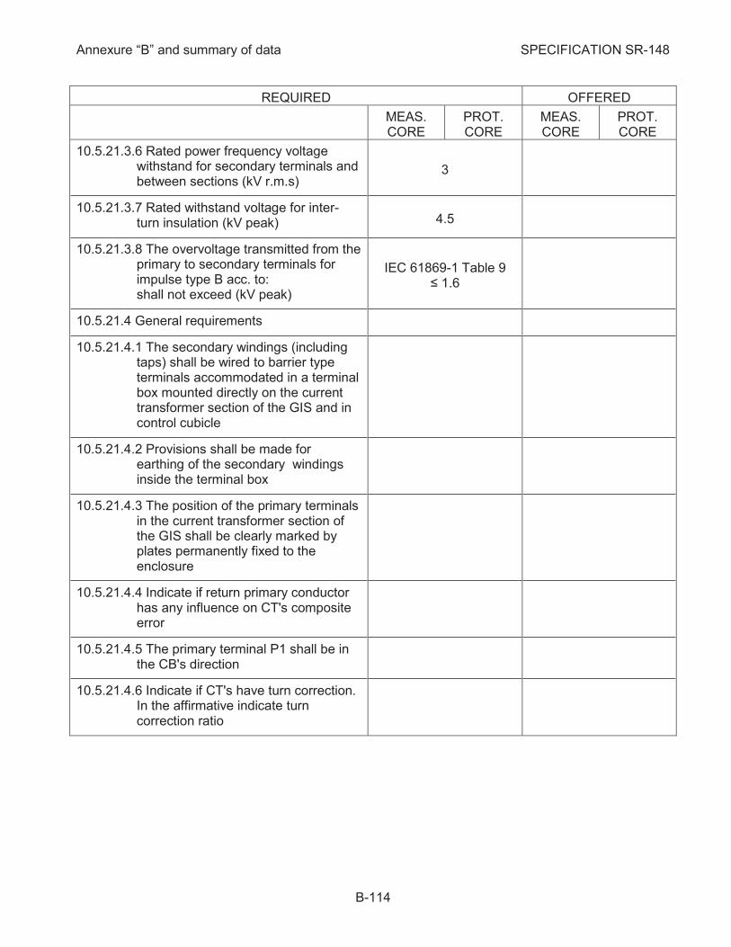
Annexure “B” and summary of data SPECIFICATION SR-148
B-114
REQUIRED OFFERED
MEAS. CORE
PROT. CORE
MEAS. CORE
PROT. CORE
10.5.21.3.6 Rated power frequency voltage withstand for secondary terminals and between sections (kV r.m.s)
3
10.5.21.3.7 Rated withstand voltage for inter-turn insulation (kV peak) 4.5
10.5.21.3.8 The overvoltage transmitted from the primary to secondary terminals for impulse type B acc. to: shall not exceed (kV peak)
IEC 61869-1 Table 9 ≤ 1.6
10.5.21.4 General requirements
10.5.21.4.1 The secondary windings (including taps) shall be wired to barrier type terminals accommodated in a terminal box mounted directly on the current transformer section of the GIS and in control cubicle
10.5.21.4.2 Provisions shall be made for earthing of the secondary windings inside the terminal box
10.5.21.4.3 The position of the primary terminals in the current transformer section of the GIS shall be clearly marked by plates permanently fixed to the enclosure
10.5.21.4.4 Indicate if return primary conductor has any influence on CT's composite error
10.5.21.4.5 The primary terminal P1 shall be in the CB's direction
10.5.21.4.6 Indicate if CT's have turn correction. In the affirmative indicate turn correction ratio
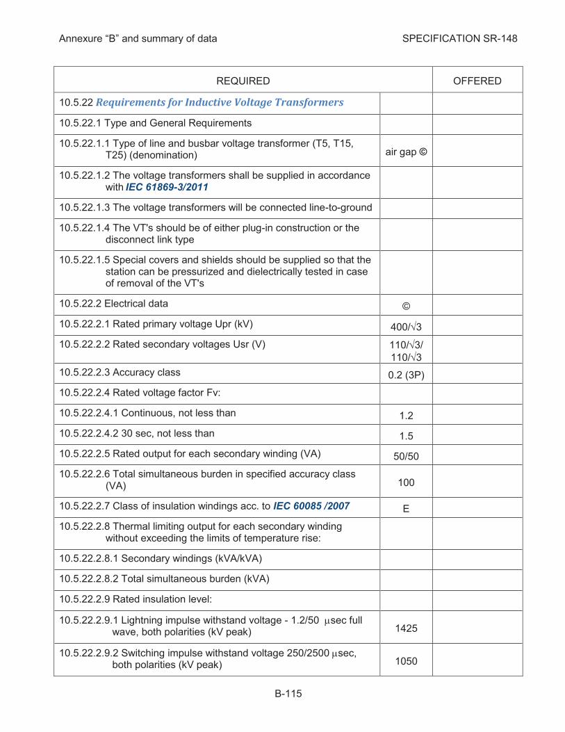
Annexure “B” and summary of data SPECIFICATION SR-148
B-115
REQUIRED OFFERED
Requirements for Inductive Voltage Transformers 10.5.22
10.5.22.1 Type and General Requirements
10.5.22.1.1 Type of line and busbar voltage transformer (T5, T15, T25) (denomination) air gap ©
10.5.22.1.2 The voltage transformers shall be supplied in accordance with IEC 61869-3/2011
10.5.22.1.3 The voltage transformers will be connected line-to-ground
10.5.22.1.4 The VT's should be of either plug-in construction or the disconnect link type
10.5.22.1.5 Special covers and shields should be supplied so that the station can be pressurized and dielectrically tested in case of removal of the VT's
10.5.22.2 Electrical data ©
10.5.22.2.1 Rated primary voltage Upr (kV) 400/Ö3
10.5.22.2.2 Rated secondary voltages Usr (V) 110/Ö3/
110/Ö3
10.5.22.2.3 Accuracy class 0.2 (3P)
10.5.22.2.4 Rated voltage factor Fv:
10.5.22.2.4.1 Continuous, not less than 1.2
10.5.22.2.4.2 30 sec, not less than 1.5
10.5.22.2.5 Rated output for each secondary winding (VA) 50/50
10.5.22.2.6 Total simultaneous burden in specified accuracy class (VA) 100
10.5.22.2.7 Class of insulation windings acc. to IEC 60085 /2007 E
10.5.22.2.8 Thermal limiting output for each secondary winding without exceeding the limits of temperature rise:
10.5.22.2.8.1 Secondary windings (kVA/kVA)
10.5.22.2.8.2 Total simultaneous burden (kVA)
10.5.22.2.9 Rated insulation level:
10.5.22.2.9.1 Lightning impulse withstand voltage - 1.2/50 msec full wave, both polarities (kV peak) 1425
10.5.22.2.9.2 Switching impulse withstand voltage 250/2500 msec, both polarities (kV peak) 1050
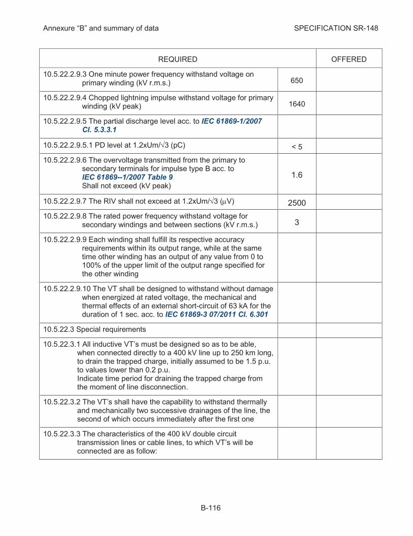
Annexure “B” and summary of data SPECIFICATION SR-148
B-116
REQUIRED OFFERED
10.5.22.2.9.3 One minute power frequency withstand voltage on primary winding (kV r.m.s.) 650
10.5.22.2.9.4 Chopped lightning impulse withstand voltage for primary winding (kV peak) 1640
10.5.22.2.9.5 The partial discharge level acc. to IEC 61869-1/2007 Cl. 5.3.3.1
10.5.22.2.9.5.1 PD level at 1.2xUm/Ö3 (pC) < 5
10.5.22.2.9.6 The overvoltage transmitted from the primary to secondary terminals for impulse type B acc. to IEC 61869--1/2007 Table 9 Shall not exceed (kV peak)
1.6
10.5.22.2.9.7 The RIV shall not exceed at 1.2xUm/Ö3 (mV) 2500
10.5.22.2.9.8 The rated power frequency withstand voltage for secondary windings and between sections (kV r.m.s.) 3
10.5.22.2.9.9 Each winding shall fulfill its respective accuracy requirements within its output range, while at the same time other winding has an output of any value from 0 to 100% of the upper limit of the output range specified for the other winding
10.5.22.2.9.10 The VT shall be designed to withstand without damage when energized at rated voltage, the mechanical and thermal effects of an external short-circuit of 63 kA for the duration of 1 sec. acc. to IEC 61869-3 07/2011 Cl. 6.301
10.5.22.3 Special requirements
10.5.22.3.1 All inductive VT’s must be designed so as to be able, when connected directly to a 400 kV line up to 250 km long, to drain the trapped charge, initially assumed to be 1.5 p.u. to values lower than 0.2 p.u. Indicate time period for draining the trapped charge from the moment of line disconnection.
10.5.22.3.2 The VT’s shall have the capability to withstand thermally and mechanically two successive drainages of the line, the second of which occurs immediately after the first one
10.5.22.3.3 The characteristics of the 400 kV double circuit transmission lines or cable lines, to which VT’s will be connected are as follow:
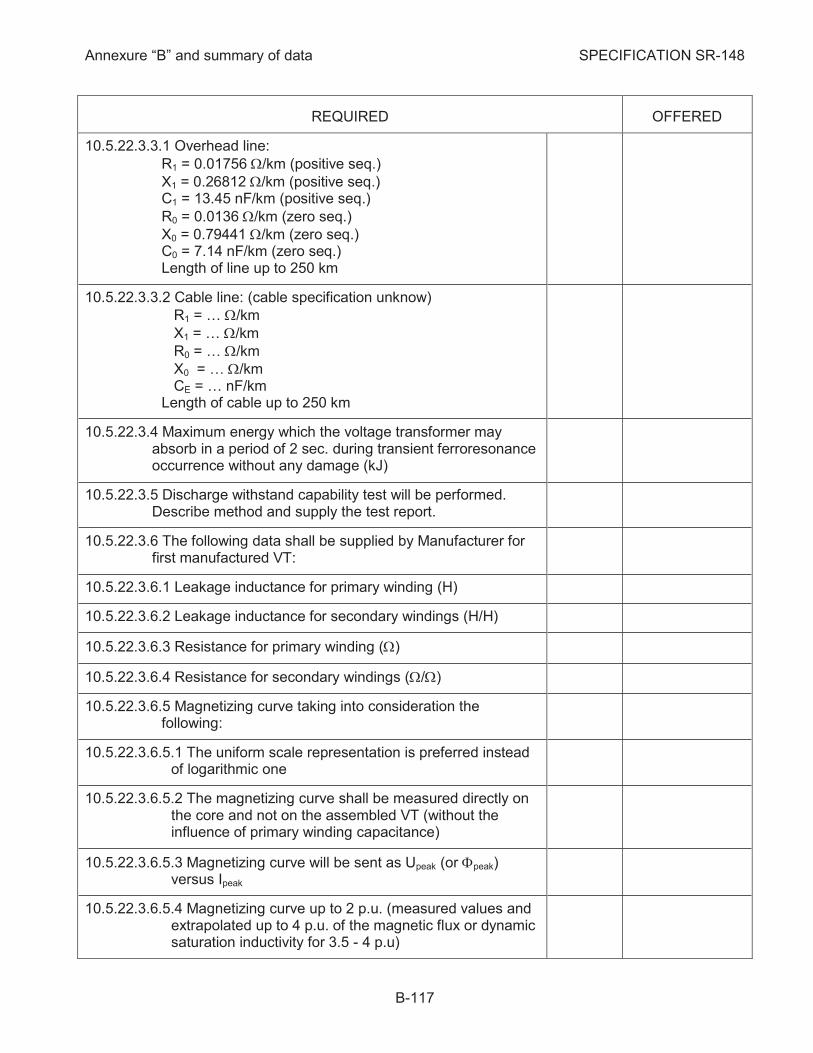
Annexure “B” and summary of data SPECIFICATION SR-148
B-117
REQUIRED OFFERED
10.5.22.3.3.1 Overhead line:
R1 = 0.01756 W/km (positive seq.)
X1 = 0.26812 W/km (positive seq.) C1 = 13.45 nF/km (positive seq.)
R0 = 0.0136 W/km (zero seq.)
X0 = 0.79441 W/km (zero seq.) C0 = 7.14 nF/km (zero seq.) Length of line up to 250 km
10.5.22.3.3.2 Cable line: (cable specification unknow)
R1 = … W/km
X1 = … W/km
R0 = … W/km
X0 = … W/km CE = … nF/km Length of cable up to 250 km
10.5.22.3.4 Maximum energy which the voltage transformer may absorb in a period of 2 sec. during transient ferroresonance occurrence without any damage (kJ)
10.5.22.3.5 Discharge withstand capability test will be performed. Describe method and supply the test report.
10.5.22.3.6 The following data shall be supplied by Manufacturer for first manufactured VT:
10.5.22.3.6.1 Leakage inductance for primary winding (H)
10.5.22.3.6.2 Leakage inductance for secondary windings (H/H)
10.5.22.3.6.3 Resistance for primary winding (W)
10.5.22.3.6.4 Resistance for secondary windings (W/W)
10.5.22.3.6.5 Magnetizing curve taking into consideration the following:
10.5.22.3.6.5.1 The uniform scale representation is preferred instead of logarithmic one
10.5.22.3.6.5.2 The magnetizing curve shall be measured directly on the core and not on the assembled VT (without the influence of primary winding capacitance)
10.5.22.3.6.5.3 Magnetizing curve will be sent as Upeak (or Fpeak) versus Ipeak
10.5.22.3.6.5.4 Magnetizing curve up to 2 p.u. (measured values and extrapolated up to 4 p.u. of the magnetic flux or dynamic saturation inductivity for 3.5 - 4 p.u)
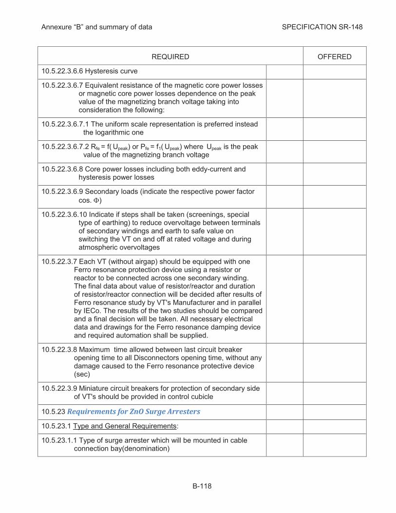
Annexure “B” and summary of data SPECIFICATION SR-148
B-118
REQUIRED OFFERED
10.5.22.3.6.6 Hysteresis curve
10.5.22.3.6.7 Equivalent resistance of the magnetic core power losses or magnetic core power losses dependence on the peak value of the magnetizing branch voltage taking into consideration the following:
10.5.22.3.6.7.1 The uniform scale representation is preferred instead the logarithmic one
10.5.22.3.6.7.2 Rfe = f( Upeak) or Pfe = f1( Upeak) where Upeak is the peak value of the magnetizing branch voltage
10.5.22.3.6.8 Core power losses including both eddy-current and hysteresis power losses
10.5.22.3.6.9 Secondary loads (indicate the respective power factor
cos. F)
10.5.22.3.6.10 Indicate if steps shall be taken (screenings, special type of earthing) to reduce overvoltage between terminals of secondary windings and earth to safe value on switching the VT on and off at rated voltage and during atmospheric overvoltages
10.5.22.3.7 Each VT (without airgap) should be equipped with one Ferro resonance protection device using a resistor or reactor to be connected across one secondary winding. The final data about value of resistor/reactor and duration of resistor/reactor connection will be decided after results of Ferro resonance study by VT's Manufacturer and in parallel by IECo. The results of the two studies should be compared and a final decision will be taken. All necessary electrical data and drawings for the Ferro resonance damping device and required automation shall be supplied.
10.5.22.3.8 Maximum time allowed between last circuit breaker opening time to all Disconnectors opening time, without any damage caused to the Ferro resonance protective device (sec)
10.5.22.3.9 Miniature circuit breakers for protection of secondary side of VT's should be provided in control cubicle
Requirements for ZnO Surge Arresters 10.5.23
10.5.23.1 Type and General Requirements:
10.5.23.1.1 Type of surge arrester which will be mounted in cable connection bay(denomination)
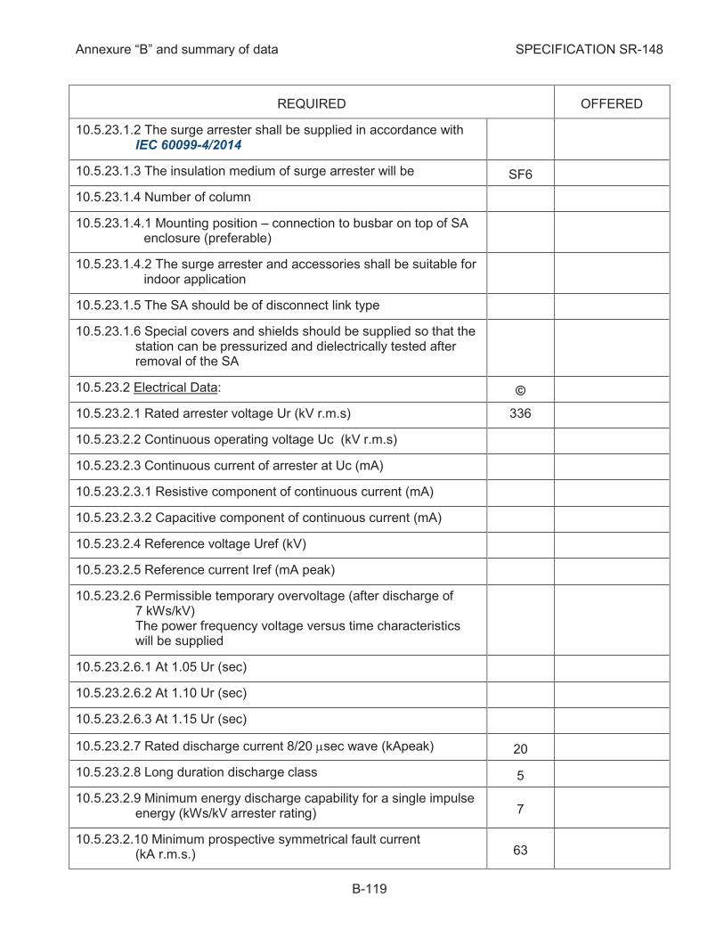
Annexure “B” and summary of data SPECIFICATION SR-148
B-119
REQUIRED OFFERED
10.5.23.1.2 The surge arrester shall be supplied in accordance with IEC 60099-4/2014
10.5.23.1.3 The insulation medium of surge arrester will be SF6
10.5.23.1.4 Number of column
10.5.23.1.4.1 Mounting position – connection to busbar on top of SA enclosure (preferable)
10.5.23.1.4.2 The surge arrester and accessories shall be suitable for indoor application
10.5.23.1.5 The SA should be of disconnect link type
10.5.23.1.6 Special covers and shields should be supplied so that the station can be pressurized and dielectrically tested after removal of the SA
10.5.23.2 Electrical Data: ©
10.5.23.2.1 Rated arrester voltage Ur (kV r.m.s) 336
10.5.23.2.2 Continuous operating voltage Uc (kV r.m.s)
10.5.23.2.3 Continuous current of arrester at Uc (mA)
10.5.23.2.3.1 Resistive component of continuous current (mA)
10.5.23.2.3.2 Capacitive component of continuous current (mA)
10.5.23.2.4 Reference voltage Uref (kV)
10.5.23.2.5 Reference current Iref (mA peak)
10.5.23.2.6 Permissible temporary overvoltage (after discharge of 7 kWs/kV) The power frequency voltage versus time characteristics will be supplied
10.5.23.2.6.1 At 1.05 Ur (sec)
10.5.23.2.6.2 At 1.10 Ur (sec)
10.5.23.2.6.3 At 1.15 Ur (sec)
10.5.23.2.7 Rated discharge current 8/20 msec wave (kApeak) 20
10.5.23.2.8 Long duration discharge class 5
10.5.23.2.9 Minimum energy discharge capability for a single impulse energy (kWs/kV arrester rating) 7
10.5.23.2.10 Minimum prospective symmetrical fault current (kA r.m.s.) 63
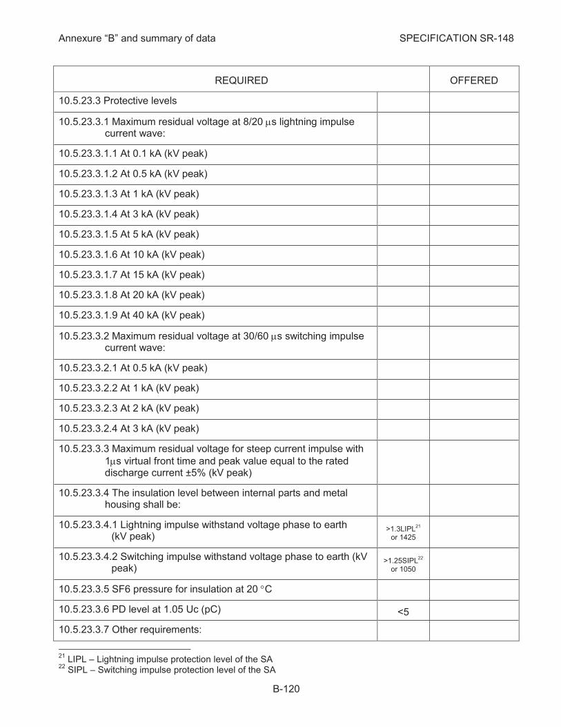
Annexure “B” and summary of data SPECIFICATION SR-148
B-120
REQUIRED OFFERED
10.5.23.3 Protective levels
10.5.23.3.1 Maximum residual voltage at 8/20 ms lightning impulse current wave:
10.5.23.3.1.1 At 0.1 kA (kV peak)
10.5.23.3.1.2 At 0.5 kA (kV peak)
10.5.23.3.1.3 At 1 kA (kV peak)
10.5.23.3.1.4 At 3 kA (kV peak)
10.5.23.3.1.5 At 5 kA (kV peak)
10.5.23.3.1.6 At 10 kA (kV peak)
10.5.23.3.1.7 At 15 kA (kV peak)
10.5.23.3.1.8 At 20 kA (kV peak)
10.5.23.3.1.9 At 40 kA (kV peak)
10.5.23.3.2 Maximum residual voltage at 30/60 ms switching impulse current wave:
10.5.23.3.2.1 At 0.5 kA (kV peak)
10.5.23.3.2.2 At 1 kA (kV peak)
10.5.23.3.2.3 At 2 kA (kV peak)
10.5.23.3.2.4 At 3 kA (kV peak)
10.5.23.3.3 Maximum residual voltage for steep current impulse with
1ms virtual front time and peak value equal to the rated discharge current ±5% (kV peak)
10.5.23.3.4 The insulation level between internal parts and metal housing shall be:
10.5.23.3.4.1 Lightning impulse withstand voltage phase to earth (kV peak)
>1.3LIPL21
or 1425
10.5.23.3.4.2 Switching impulse withstand voltage phase to earth (kV peak)
>1.25SIPL22
or 1050
10.5.23.3.5 SF6 pressure for insulation at 20 °C
10.5.23.3.6 PD level at 1.05 Uc (pC) <5
10.5.23.3.7 Other requirements:
21
LIPL – Lightning impulse protection level of the SA 22
SIPL – Switching impulse protection level of the SA
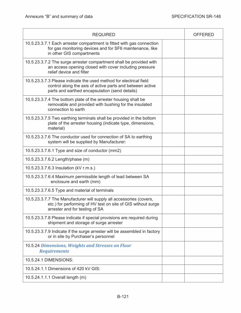
Annexure “B” and summary of data SPECIFICATION SR-148
B-121
REQUIRED OFFERED
10.5.23.3.7.1 Each arrester compartment is fitted with gas connection for gas monitoring devices and for SF6 maintenance, like in other GIS compartments
10.5.23.3.7.2 The surge arrester compartment shall be provided with an access opening closed with cover including pressure relief device and filter
10.5.23.3.7.3 Please indicate the used method for electrical field control along the axis of active parts and between active parts and earthed encapsulation (send details)
10.5.23.3.7.4 The bottom plate of the arrester housing shall be removable and provided with bushing for the insulated connection to earth
10.5.23.3.7.5 Two earthing terminals shall be provided in the bottom plate of the arrester housing (indicate type, dimensions, material)
10.5.23.3.7.6 The conductor used for connection of SA to earthing system will be supplied by Manufacturer:
10.5.23.3.7.6.1 Type and size of conductor (mm2)
10.5.23.3.7.6.2 Length/phase (m)
10.5.23.3.7.6.3 Insulation (kV r.m.s.)
10.5.23.3.7.6.4 Maximum permissible length of lead between SA enclosure and earth (mm)
10.5.23.3.7.6.5 Type and material of terminals
10.5.23.3.7.7 The Manufacturer will supply all accessories (covers, etc.) for performing of HV test on site of GIS without surge arrester and for testing of SA
10.5.23.3.7.8 Please indicate if special provisions are required during shipment and storage of surge arrester
10.5.23.3.7.9 Indicate if the surge arrester will be assembled in factory or in site by Purchaser’s personnel
Dimensions, Weights and Stresses on Floor 10.5.24
Requirements
10.5.24.1 DIMENSIONS:
10.5.24.1.1 Dimensions of 420 kV GIS:
10.5.24.1.1.1 Overall length (m)

Annexure “B” and summary of data SPECIFICATION SR-148
B-122
REQUIRED OFFERED
10.5.24.1.1.2 Overall width (without connections to lines or autotransformers) (m)
10.5.24.1.1.3 Maximum height (inside the building) (m)
10.5.24.1.1.4 Distance between axes of adjacent bays (m)
10.5.24.1.2 The recommended dimensions of the GIS room:
10.5.24.1.2.1 Length (m)
10.5.24.1.2.2 Width (inside columns) (m) 0.6
10.5.24.1.2.3 Height to crane hook (m) 2.2
10.5.24.1.2.4 Recommended height for crane mounting (m)
10.5.24.1.2.5 Minimum distance between crane and walls building (m)
10.5.24.1.2.6 The distance between SF6 ducts axis parallel with the wall and wall's building shall be higher than (mm) 1000
10.5.24.1.2.7 The distance between GIS and the control cubicles in front of it shall be minimum (m) 2.2 ©
10.5.24.1.2.8 If a basement is needed the height of the ceiling will be minimum (m) 4
10.5.24.1.3 Gas Filling, Evacuating and Processing Equipment:
10.5.24.1.3.1 Length (m)
10.5.24.1.3.2 Width (m)
10.5.24.1.3.3 Height (m)
10.5.24.1.4 Typical dimensions of a local control cubicle:
10.5.24.1.4.1 Length (m)
10.5.24.1.4.2 Width (m)
10.5.24.1.4.3 Height (m) 2.2
10.5.24.1.5 Dimensions required for opening in the building for introducing SF6 equipment:
10.5.24.1.5.1 Width (m)
10.5.24.1.5.2 Height (m)
10.5.24.2 WEIGHTS
10.5.24.2.1 Weight of heaviest bay (fully equipped) (ton)
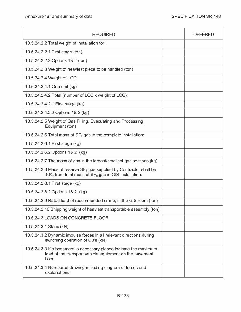
Annexure “B” and summary of data SPECIFICATION SR-148
B-123
REQUIRED OFFERED
10.5.24.2.2 Total weight of installation for:
10.5.24.2.2.1 First stage (ton)
10.5.24.2.2.2 Options 1& 2 (ton)
10.5.24.2.3 Weight of heaviest piece to be handled (ton)
10.5.24.2.4 Weight of LCC:
10.5.24.2.4.1 One unit (kg)
10.5.24.2.4.2 Total (number of LCC x weight of LCC):
10.5.24.2.4.2.1 First stage (kg)
10.5.24.2.4.2.2 Options 1& 2 (kg)
10.5.24.2.5 Weight of Gas Filling, Evacuating and Processing Equipment (ton)
10.5.24.2.6 Total mass of SF6 gas in the complete installation:
10.5.24.2.6.1 First stage (kg)
10.5.24.2.6.2 Options 1& 2 (kg)
10.5.24.2.7 The mass of gas in the largest/smallest gas sections (kg)
10.5.24.2.8 Mass of reserve SF6 gas supplied by Contractor shall be 10% from total mass of SF6 gas in GIS installation:
10.5.24.2.8.1 First stage (kg)
10.5.24.2.8.2 Options 1& 2 (kg)
10.5.24.2.9 Rated load of recommended crane, in the GIS room (ton)
10.5.24.2.10 Shipping weight of heaviest transportable assembly (ton)
10.5.24.3 LOADS ON CONCRETE FLOOR
10.5.24.3.1 Static (kN)
10.5.24.3.2 Dynamic impulse forces in all relevant directions during switching operation of CB's (kN)
10.5.24.3.3 If a basement is necessary please indicate the maximum load of the transport vehicle equipment on the basement floor
10.5.24.3.4 Number of drawing including diagram of forces and explanations
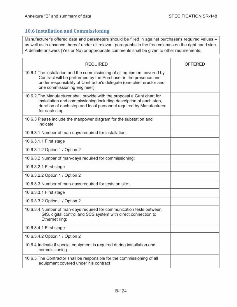
Annexure “B” and summary of data SPECIFICATION SR-148
B-124
10.6 Installation and Commissioning
Manufacturer's offered data and parameters should be filled in against purchaser's required values –
as well as in absence thereof under all relevant paragraphs in the free columns on the right hand side.
A definite answers (Yes or No) or appropriate comments shall be given to other requirements.
REQUIRED OFFERED
The installation and the commissioning of all equipment covered by 10.6.1Contract will be performed by the Purchaser in the presence and under responsibility of Contractor's delegate (one chief erector and one commissioning engineer)
The Manufacturer shall provide with the proposal a Gant chart for 10.6.2installation and commissioning including description of each step, duration of each step and local personnel required by Manufacturer for each step
Please include the manpower diagram for the substation and 10.6.3indicate:
10.6.3.1 Number of man-days required for installation:
10.6.3.1.1 First stage
10.6.3.1.2 Option 1 / Option 2
10.6.3.2 Number of man-days required for commissioning:
10.6.3.2.1 First stage
10.6.3.2.2 Option 1 / Option 2
10.6.3.3 Number of man-days required for tests on site:
10.6.3.3.1 First stage
10.6.3.3.2 Option 1 / Option 2
10.6.3.4 Number of man-days required for communication tests between GIS, digital control and SCS system with direct connection to Ethernet ring:
10.6.3.4.1 First stage
10.6.3.4.2 Option 1 / Option 2
Indicate if special equipment is required during installation and 10.6.4commissioning
The Contractor shall be responsible for the commissioning of all 10.6.5equipment covered under his contract
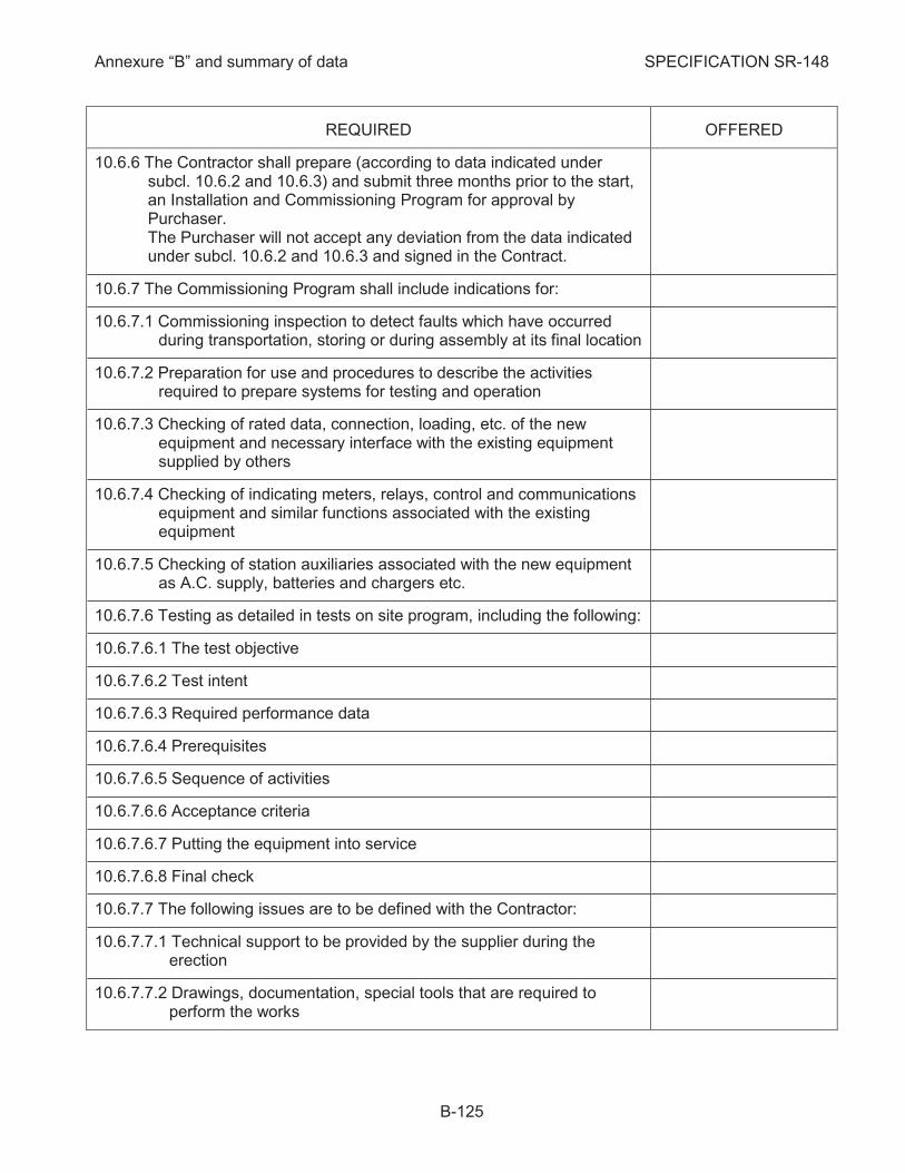
Annexure “B” and summary of data SPECIFICATION SR-148
B-125
REQUIRED OFFERED
The Contractor shall prepare (according to data indicated under 10.6.6subcl. 10.6.2 and 10.6.3) and submit three months prior to the start, an Installation and Commissioning Program for approval by Purchaser. The Purchaser will not accept any deviation from the data indicated under subcl. 10.6.2 and 10.6.3 and signed in the Contract.
The Commissioning Program shall include indications for: 10.6.7
10.6.7.1 Commissioning inspection to detect faults which have occurred during transportation, storing or during assembly at its final location
10.6.7.2 Preparation for use and procedures to describe the activities required to prepare systems for testing and operation
10.6.7.3 Checking of rated data, connection, loading, etc. of the new equipment and necessary interface with the existing equipment supplied by others
10.6.7.4 Checking of indicating meters, relays, control and communications equipment and similar functions associated with the existing equipment
10.6.7.5 Checking of station auxiliaries associated with the new equipment as A.C. supply, batteries and chargers etc.
10.6.7.6 Testing as detailed in tests on site program, including the following:
10.6.7.6.1 The test objective
10.6.7.6.2 Test intent
10.6.7.6.3 Required performance data
10.6.7.6.4 Prerequisites
10.6.7.6.5 Sequence of activities
10.6.7.6.6 Acceptance criteria
10.6.7.6.7 Putting the equipment into service
10.6.7.6.8 Final check
10.6.7.7 The following issues are to be defined with the Contractor:
10.6.7.7.1 Technical support to be provided by the supplier during the erection
10.6.7.7.2 Drawings, documentation, special tools that are required to perform the works
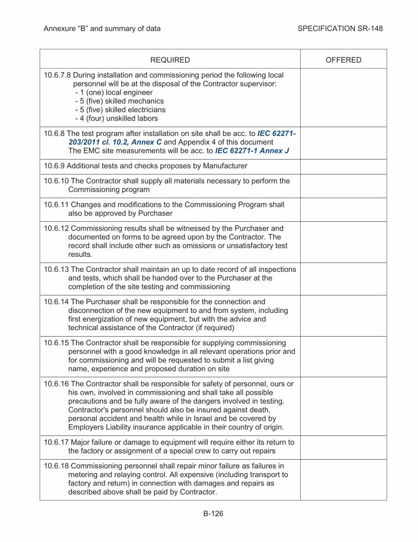
Annexure “B” and summary of data SPECIFICATION SR-148
B-126
REQUIRED OFFERED
10.6.7.8 During installation and commissioning period the following local personnel will be at the disposal of the Contractor supervisor: - 1 (one) local engineer - 5 (five) skilled mechanics - 5 (five) skilled electricians - 4 (four) unskilled labors
The test program after installation on site shall be acc. to IEC 62271-10.6.8203/2011 cl. 10.2, Annex C and Appendix 4 of this document The EMC site measurements will be acc. to IEC 62271-1 Annex J
Additional tests and checks proposes by Manufacturer 10.6.9
The Contractor shall supply all materials necessary to perform the 10.6.10Commissioning program
Changes and modifications to the Commissioning Program shall 10.6.11also be approved by Purchaser
Commissioning results shall be witnessed by the Purchaser and 10.6.12documented on forms to be agreed upon by the Contractor. The record shall include other such as omissions or unsatisfactory test results.
The Contractor shall maintain an up to date record of all inspections 10.6.13and tests, which shall be handed over to the Purchaser at the completion of the site testing and commissioning
The Purchaser shall be responsible for the connection and 10.6.14disconnection of the new equipment to and from system, including first energization of new equipment, but with the advice and technical assistance of the Contractor (if required)
The Contractor shall be responsible for supplying commissioning 10.6.15personnel with a good knowledge in all relevant operations prior and for commissioning and will be requested to submit a list giving name, experience and proposed duration on site
The Contractor shall be responsible for safety of personnel, ours or 10.6.16his own, involved in commissioning and shall take all possible precautions and be fully aware of the dangers involved in testing. Contractor's personnel should also be insured against death, personal accident and health while in Israel and be covered by Employers Liability insurance applicable in their country of origin.
Major failure or damage to equipment will require either its return to 10.6.17the factory or assignment of a special crew to carry out repairs
Commissioning personnel shall repair minor failure as failures in 10.6.18metering and relaying control. All expensive (including transport to factory and return) in connection with damages and repairs as described above shall be paid by Contractor.
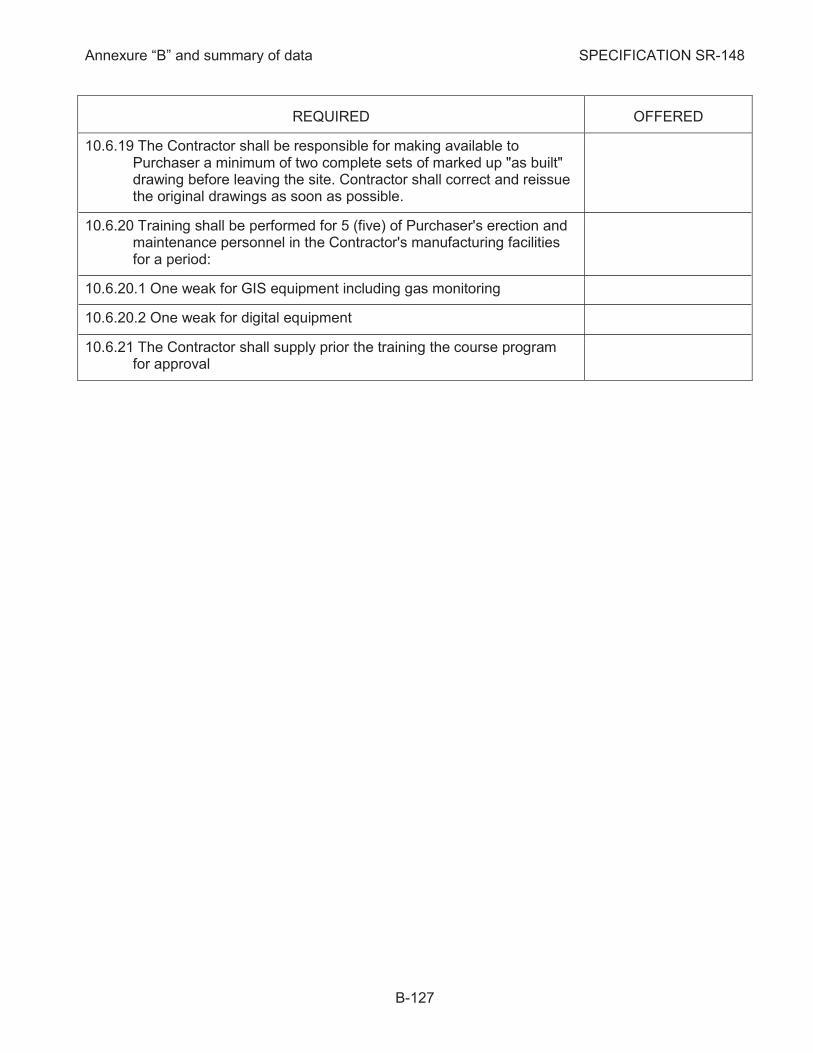
Annexure “B” and summary of data SPECIFICATION SR-148
B-127
REQUIRED OFFERED
The Contractor shall be responsible for making available to 10.6.19Purchaser a minimum of two complete sets of marked up "as built" drawing before leaving the site. Contractor shall correct and reissue the original drawings as soon as possible.
Training shall be performed for 5 (five) of Purchaser's erection and 10.6.20maintenance personnel in the Contractor's manufacturing facilities for a period:
10.6.20.1 One weak for GIS equipment including gas monitoring
10.6.20.2 One weak for digital equipment
The Contractor shall supply prior the training the course program 10.6.21for approval
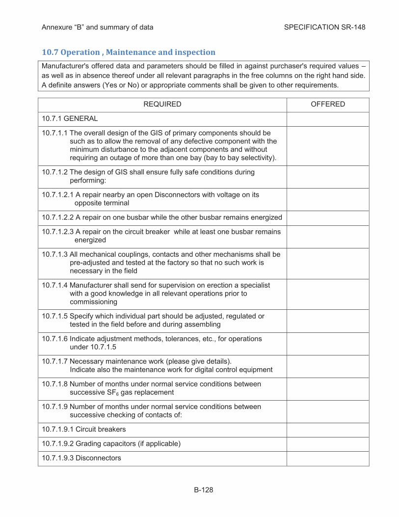
Annexure “B” and summary of data SPECIFICATION SR-148
B-128
10.7 Operation , Maintenance and inspection
Manufacturer's offered data and parameters should be filled in against purchaser's required values –
as well as in absence thereof under all relevant paragraphs in the free columns on the right hand side.
A definite answers (Yes or No) or appropriate comments shall be given to other requirements.
REQUIRED OFFERED
GENERAL 10.7.1
10.7.1.1 The overall design of the GIS of primary components should be such as to allow the removal of any defective component with the minimum disturbance to the adjacent components and without requiring an outage of more than one bay (bay to bay selectivity).
10.7.1.2 The design of GIS shall ensure fully safe conditions during performing:
10.7.1.2.1 A repair nearby an open Disconnectors with voltage on its opposite terminal
10.7.1.2.2 A repair on one busbar while the other busbar remains energized
10.7.1.2.3 A repair on the circuit breaker while at least one busbar remains energized
10.7.1.3 All mechanical couplings, contacts and other mechanisms shall be pre-adjusted and tested at the factory so that no such work is necessary in the field
10.7.1.4 Manufacturer shall send for supervision on erection a specialist with a good knowledge in all relevant operations prior to commissioning
10.7.1.5 Specify which individual part should be adjusted, regulated or tested in the field before and during assembling
10.7.1.6 Indicate adjustment methods, tolerances, etc., for operations under 10.7.1.5
10.7.1.7 Necessary maintenance work (please give details). Indicate also the maintenance work for digital control equipment
10.7.1.8 Number of months under normal service conditions between successive SF6 gas replacement
10.7.1.9 Number of months under normal service conditions between successive checking of contacts of:
10.7.1.9.1 Circuit breakers
10.7.1.9.2 Grading capacitors (if applicable)
10.7.1.9.3 Disconnectors
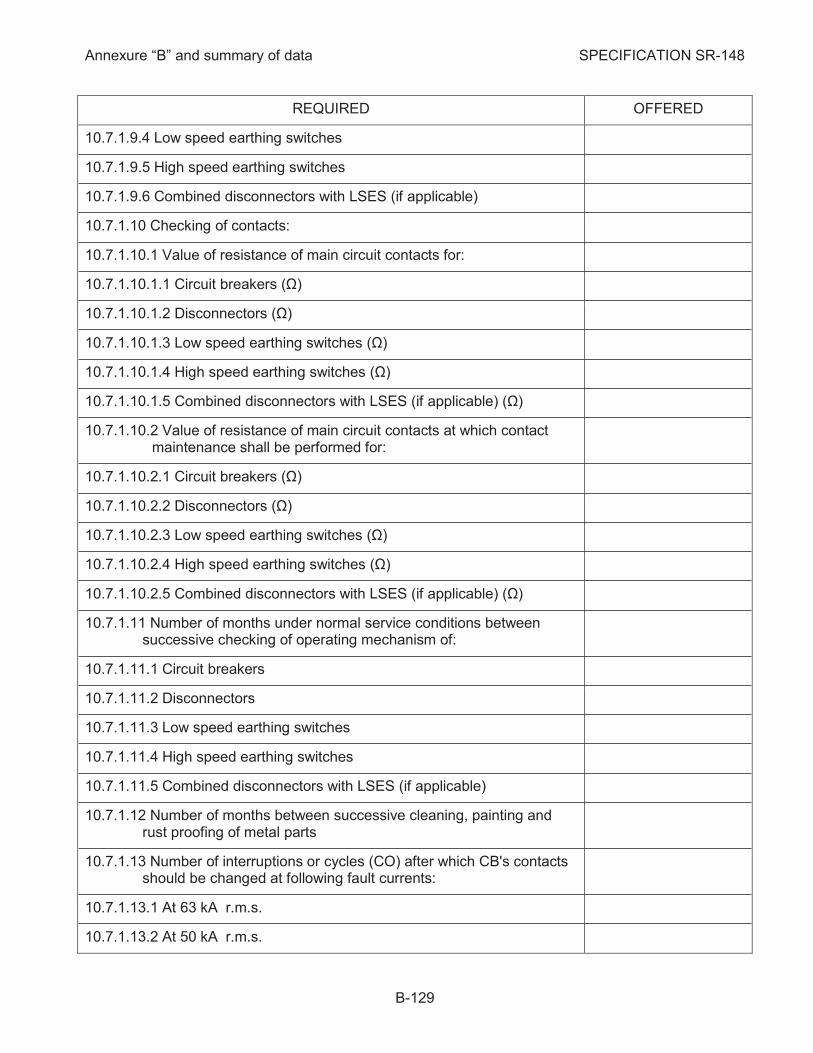
Annexure “B” and summary of data SPECIFICATION SR-148
B-129
REQUIRED OFFERED
10.7.1.9.4 Low speed earthing switches
10.7.1.9.5 High speed earthing switches
10.7.1.9.6 Combined disconnectors with LSES (if applicable)
10.7.1.10 Checking of contacts:
10.7.1.10.1 Value of resistance of main circuit contacts for:
10.7.1.10.1.1 Circuit breakers (Ω)
10.7.1.10.1.2 Disconnectors (Ω)
10.7.1.10.1.3 Low speed earthing switches (Ω)
10.7.1.10.1.4 High speed earthing switches (Ω)
10.7.1.10.1.5 Combined disconnectors with LSES (if applicable) (Ω)
10.7.1.10.2 Value of resistance of main circuit contacts at which contact maintenance shall be performed for:
10.7.1.10.2.1 Circuit breakers (Ω)
10.7.1.10.2.2 Disconnectors (Ω)
10.7.1.10.2.3 Low speed earthing switches (Ω)
10.7.1.10.2.4 High speed earthing switches (Ω)
10.7.1.10.2.5 Combined disconnectors with LSES (if applicable) (Ω)
10.7.1.11 Number of months under normal service conditions between successive checking of operating mechanism of:
10.7.1.11.1 Circuit breakers
10.7.1.11.2 Disconnectors
10.7.1.11.3 Low speed earthing switches
10.7.1.11.4 High speed earthing switches
10.7.1.11.5 Combined disconnectors with LSES (if applicable)
10.7.1.12 Number of months between successive cleaning, painting and rust proofing of metal parts
10.7.1.13 Number of interruptions or cycles (CO) after which CB's contacts should be changed at following fault currents:
10.7.1.13.1 At 63 kA r.m.s.
10.7.1.13.2 At 50 kA r.m.s.
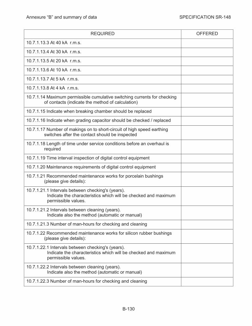
Annexure “B” and summary of data SPECIFICATION SR-148
B-130
REQUIRED OFFERED
10.7.1.13.3 At 40 kA r.m.s.
10.7.1.13.4 At 30 kA r.m.s.
10.7.1.13.5 At 20 kA r.m.s.
10.7.1.13.6 At 10 kA r.m.s.
10.7.1.13.7 At 5 kA r.m.s.
10.7.1.13.8 At 4 kA r.m.s.
10.7.1.14 Maximum permissible cumulative switching currents for checking of contacts (indicate the method of calculation)
10.7.1.15 Indicate when breaking chamber should be replaced
10.7.1.16 Indicate when grading capacitor should be checked / replaced
10.7.1.17 Number of makings on to short-circuit of high speed earthing switches after the contact should be inspected
10.7.1.18 Length of time under service conditions before an overhaul is required
10.7.1.19 Time interval inspection of digital control equipment
10.7.1.20 Maintenance requirements of digital control equipment
10.7.1.21 Recommended maintenance works for porcelain bushings (please give details):
10.7.1.21.1 Intervals between checking's (years). Indicate the characteristics which will be checked and maximum permissible values.
10.7.1.21.2 Intervals between cleaning (years). Indicate also the method (automatic or manual)
10.7.1.21.3 Number of man-hours for checking and cleaning
10.7.1.22 Recommended maintenance works for silicon rubber bushings (please give details):
10.7.1.22.1 Intervals between checking's (years). Indicate the characteristics which will be checked and maximum permissible values.
10.7.1.22.2 Intervals between cleaning (years). Indicate also the method (automatic or manual)
10.7.1.22.3 Number of man-hours for checking and cleaning
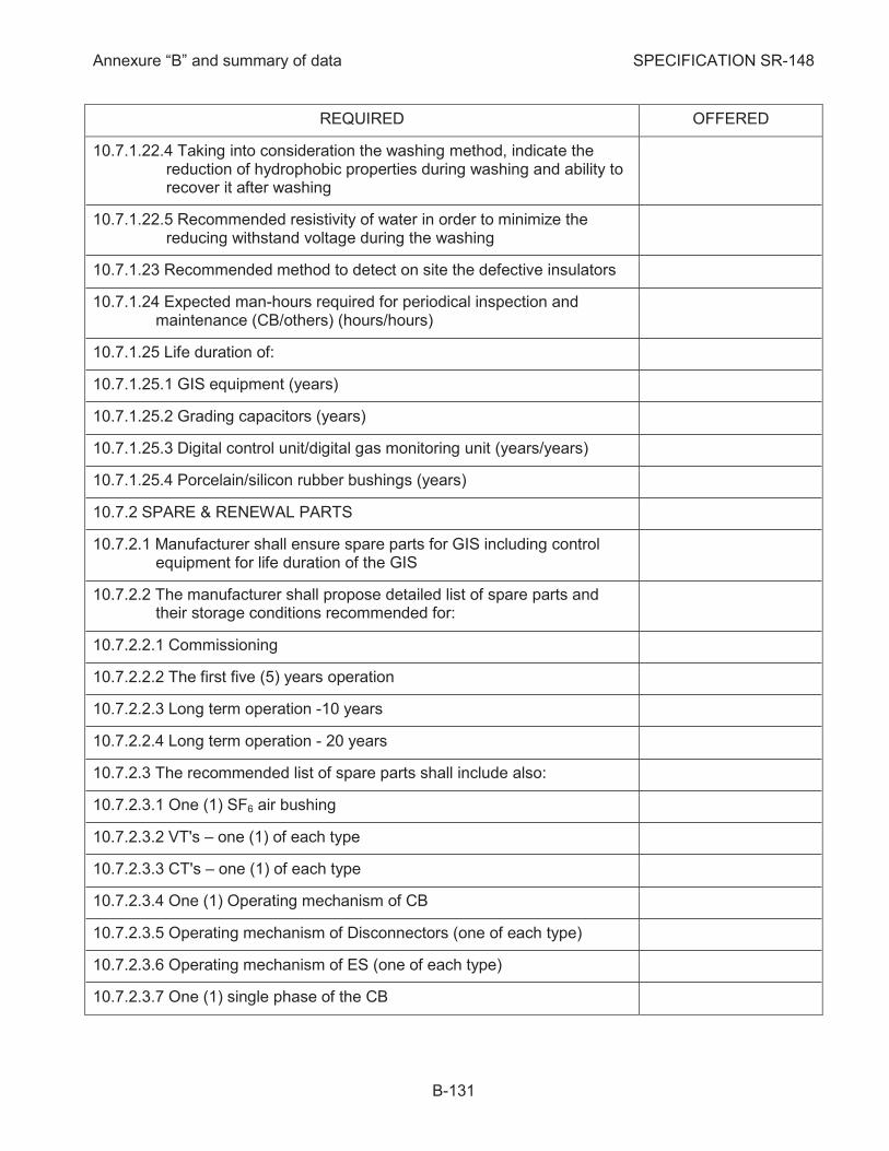
Annexure “B” and summary of data SPECIFICATION SR-148
B-131
REQUIRED OFFERED
10.7.1.22.4 Taking into consideration the washing method, indicate the reduction of hydrophobic properties during washing and ability to recover it after washing
10.7.1.22.5 Recommended resistivity of water in order to minimize the reducing withstand voltage during the washing
10.7.1.23 Recommended method to detect on site the defective insulators
10.7.1.24 Expected man-hours required for periodical inspection and maintenance (CB/others) (hours/hours)
10.7.1.25 Life duration of:
10.7.1.25.1 GIS equipment (years)
10.7.1.25.2 Grading capacitors (years)
10.7.1.25.3 Digital control unit/digital gas monitoring unit (years/years)
10.7.1.25.4 Porcelain/silicon rubber bushings (years)
SPARE & RENEWAL PARTS 10.7.2
10.7.2.1 Manufacturer shall ensure spare parts for GIS including control equipment for life duration of the GIS
10.7.2.2 The manufacturer shall propose detailed list of spare parts and their storage conditions recommended for:
10.7.2.2.1 Commissioning
10.7.2.2.2 The first five (5) years operation
10.7.2.2.3 Long term operation -10 years
10.7.2.2.4 Long term operation - 20 years
10.7.2.3 The recommended list of spare parts shall include also:
10.7.2.3.1 One (1) SF6 air bushing
10.7.2.3.2 VT's – one (1) of each type
10.7.2.3.3 CT's – one (1) of each type
10.7.2.3.4 One (1) Operating mechanism of CB
10.7.2.3.5 Operating mechanism of Disconnectors (one of each type)
10.7.2.3.6 Operating mechanism of ES (one of each type)
10.7.2.3.7 One (1) single phase of the CB
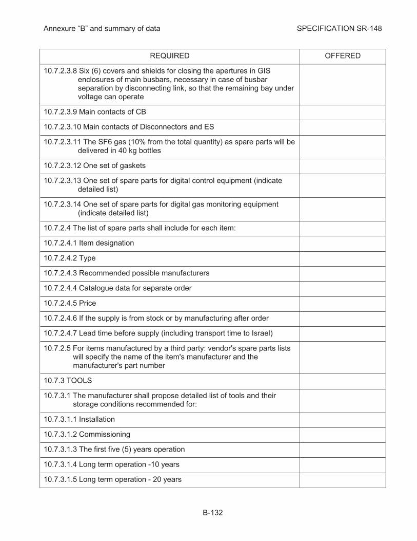
Annexure “B” and summary of data SPECIFICATION SR-148
B-132
REQUIRED OFFERED
10.7.2.3.8 Six (6) covers and shields for closing the apertures in GIS enclosures of main busbars, necessary in case of busbar separation by disconnecting link, so that the remaining bay under voltage can operate
10.7.2.3.9 Main contacts of CB
10.7.2.3.10 Main contacts of Disconnectors and ES
10.7.2.3.11 The SF6 gas (10% from the total quantity) as spare parts will be delivered in 40 kg bottles
10.7.2.3.12 One set of gaskets
10.7.2.3.13 One set of spare parts for digital control equipment (indicate detailed list)
10.7.2.3.14 One set of spare parts for digital gas monitoring equipment (indicate detailed list)
10.7.2.4 The list of spare parts shall include for each item:
10.7.2.4.1 Item designation
10.7.2.4.2 Type
10.7.2.4.3 Recommended possible manufacturers
10.7.2.4.4 Catalogue data for separate order
10.7.2.4.5 Price
10.7.2.4.6 If the supply is from stock or by manufacturing after order
10.7.2.4.7 Lead time before supply (including transport time to Israel)
10.7.2.5 For items manufactured by a third party: vendor's spare parts lists will specify the name of the item's manufacturer and the manufacturer's part number
TOOLS 10.7.3
10.7.3.1 The manufacturer shall propose detailed list of tools and their storage conditions recommended for:
10.7.3.1.1 Installation
10.7.3.1.2 Commissioning
10.7.3.1.3 The first five (5) years operation
10.7.3.1.4 Long term operation -10 years
10.7.3.1.5 Long term operation - 20 years
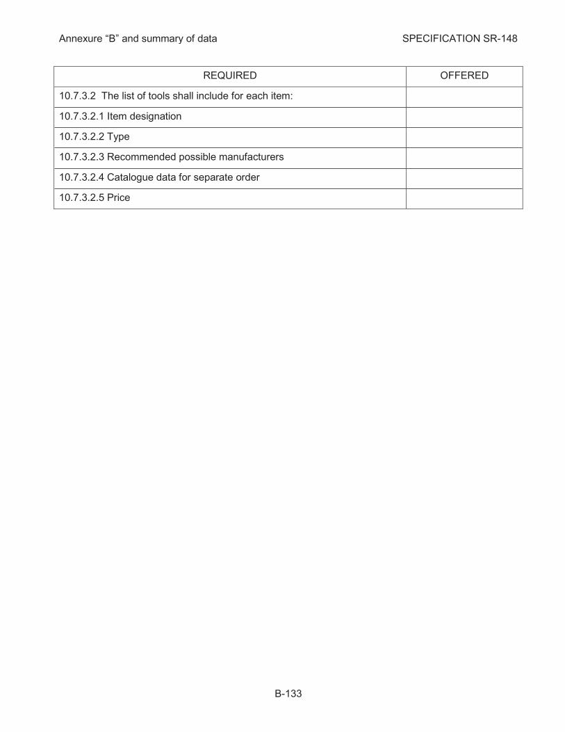
Annexure “B” and summary of data SPECIFICATION SR-148
B-133
REQUIRED OFFERED
10.7.3.2 The list of tools shall include for each item:
10.7.3.2.1 Item designation
10.7.3.2.2 Type
10.7.3.2.3 Recommended possible manufacturers
10.7.3.2.4 Catalogue data for separate order
10.7.3.2.5 Price
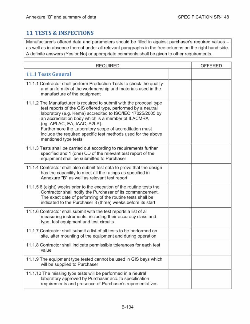
Annexure “B” and summary of data SPECIFICATION SR-148
B-134
11 TESTS & INSPECTIONS
Manufacturer's offered data and parameters should be filled in against purchaser's required values –
as well as in absence thereof under all relevant paragraphs in the free columns on the right hand side.
A definite answers (Yes or No) or appropriate comments shall be given to other requirements.
REQUIRED OFFERED
11.1 Tests General
Contractor shall perform Production Tests to check the quality 11.1.1and uniformity of the workmanship and materials used in the manufacture of the equipment
The Manufacturer is required to submit with the proposal type 11.1.2test reports of the GIS offered type, performed by a neutral laboratory (e.g. Kema) accredited to ISO/IEC 17025/2005 by an accreditation body which is a member of ILACMRA (eg. APLAC, EA, IAAC, A2LA). Furthermore the Laboratory scope of accreditation must include the required specific test methods used for the above mentioned type tests
Tests shall be carried out according to requirements further 11.1.3specified and 1 (one) CD of the relevant test report of the equipment shall be submitted to Purchaser
Contractor shall also submit test data to prove that the design 11.1.4has the capability to meet all the ratings as specified in Annexure "B" as well as relevant test report
8 (eight) weeks prior to the execution of the routine tests the 11.1.5Contractor shall notify the Purchaser of its commencement. The exact date of performing of the routine tests shall be indicated to the Purchaser 3 (three) weeks before its start
Contractor shall submit with the test reports a list of all 11.1.6measuring instruments, including their accuracy class and type, test equipment and test circuits
Contractor shall submit a list of all tests to be performed on 11.1.7site, after mounting of the equipment and during operation
Contractor shall indicate permissible tolerances for each test 11.1.8value
The equipment type tested cannot be used in GIS bays which 11.1.9will be supplied to Purchaser
The missing type tests will be performed in a neutral 11.1.10laboratory approved by Purchaser acc. to specification requirements and presence of Purchaser's representatives
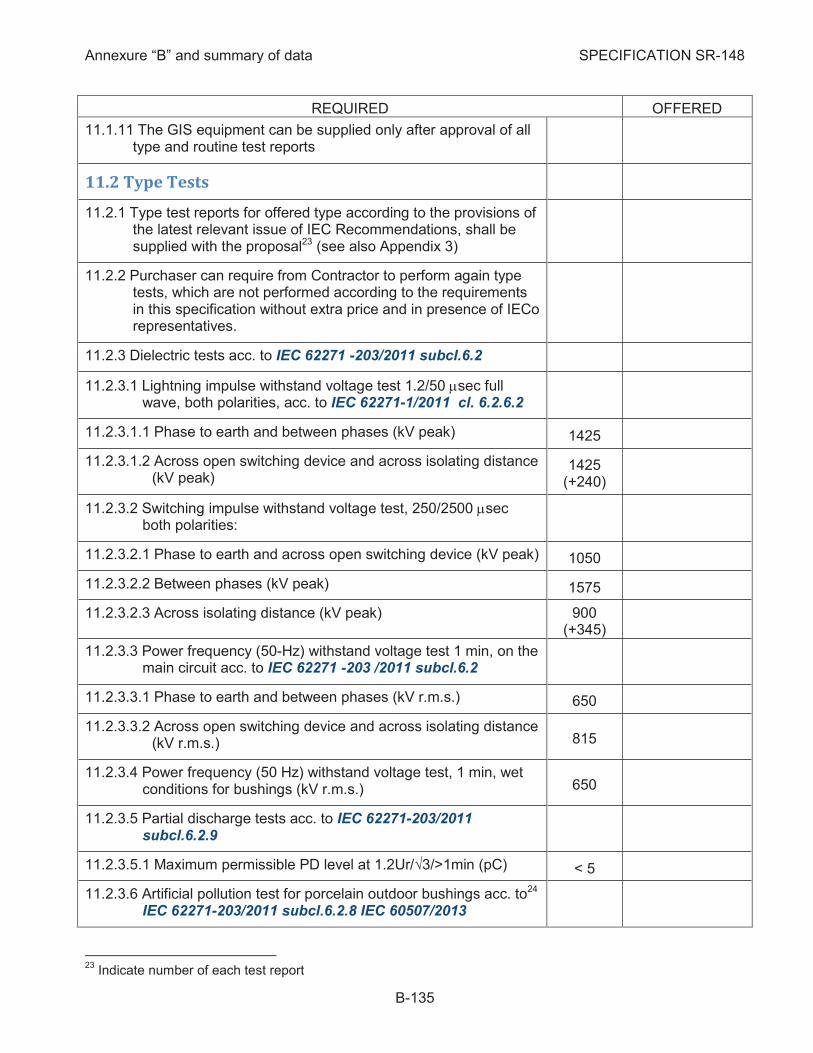
Annexure “B” and summary of data SPECIFICATION SR-148
B-135
REQUIRED OFFERED
The GIS equipment can be supplied only after approval of all 11.1.11type and routine test reports
11.2 Type Tests
Type test reports for offered type according to the provisions of 11.2.1the latest relevant issue of IEC Recommendations, shall be supplied with the proposal23 (see also Appendix 3)
Purchaser can require from Contractor to perform again type 11.2.2tests, which are not performed according to the requirements in this specification without extra price and in presence of IECo representatives.
Dielectric tests acc. to IEC 62271 -203/2011 subcl.6.2 11.2.3
11.2.3.1 Lightning impulse withstand voltage test 1.2/50 msec full wave, both polarities, acc. to IEC 62271-1/2011 cl. 6.2.6.2
11.2.3.1.1 Phase to earth and between phases (kV peak) 1425
11.2.3.1.2 Across open switching device and across isolating distance (kV peak)
1425 (+240)
11.2.3.2 Switching impulse withstand voltage test, 250/2500 msec both polarities:
11.2.3.2.1 Phase to earth and across open switching device (kV peak) 1050
11.2.3.2.2 Between phases (kV peak) 1575
11.2.3.2.3 Across isolating distance (kV peak) 900 (+345)
11.2.3.3 Power frequency (50-Hz) withstand voltage test 1 min, on the main circuit acc. to IEC 62271 -203 /2011 subcl.6.2
11.2.3.3.1 Phase to earth and between phases (kV r.m.s.) 650
11.2.3.3.2 Across open switching device and across isolating distance (kV r.m.s.) 815
11.2.3.4 Power frequency (50 Hz) withstand voltage test, 1 min, wet conditions for bushings (kV r.m.s.) 650
11.2.3.5 Partial discharge tests acc. to IEC 62271-203/2011 subcl.6.2.9
11.2.3.5.1 Maximum permissible PD level at 1.2Ur/√3/>1min (pC) < 5
11.2.3.6 Artificial pollution test for porcelain outdoor bushings acc. to24 IEC 62271-203/2011 subcl.6.2.8 IEC 60507/2013
23
Indicate number of each test report
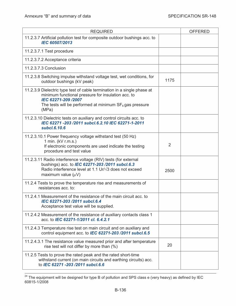
Annexure “B” and summary of data SPECIFICATION SR-148
B-136
REQUIRED OFFERED
11.2.3.7 Artificial pollution test for composite outdoor bushings acc. to IEC 60507/2013
11.2.3.7.1 Test procedure
11.2.3.7.2 Acceptance criteria
11.2.3.7.3 Conclusion
11.2.3.8 Switching impulse withstand voltage test, wet conditions, for outdoor bushings (kV peak) 1175
11.2.3.9 Dielectric type test of cable termination in a single phase at minimum functional pressure for insulation acc. to IEC 62271-209 /2007 The tests will be performed at minimum SF6 gas pressure (MPa)
11.2.3.10 Dielectric tests on auxiliary and control circuits acc. to IEC 62271 -203 /2011 subcl.6.2.10 IEC 62271-1-2011 subcl.6.10.6
11.2.3.10.1 Power frequency voltage withstand test (50 Hz) 1 min. (kV r.m.s.) If electronic components are used indicate the testing procedure and test value
2
11.2.3.11 Radio interference voltage (RIV) tests (for external bushings) acc. to IEC 62271-203 /2011 subcl.6.3 Radio interference level at 1.1 Ur/√3 does not exceed maximum value (mV)
2500
Tests to prove the temperature rise and measurements of 11.2.4resistances acc. to:
11.2.4.1 Measurement of the resistance of the main circuit acc. to IEC 62271-203 /2011 subcl.6.4 Acceptance test value will be supplied.
11.2.4.2 Measurement of the resistance of auxiliary contacts class 1 acc. to IEC 62271-1/2011 cl. 6.4.2.1
11.2.4.3 Temperature rise test on main circuit and on auxiliary and control equipment acc. to IEC 62271-203 /2011 subcl.6.5
11.2.4.3.1 The resistance value measured prior and after temperature rise test will not differ by more than (%) 20
Tests to prove the rated peak and the rated short-time 11.2.5withstand current (on main circuits and earthing circuits) acc. to IEC 62271 -203 /2011 subcl.6.6
24
The equipment will be designed for type B of pollution and SPS class e (very heavy) as defined by IEC 60815-1/2008
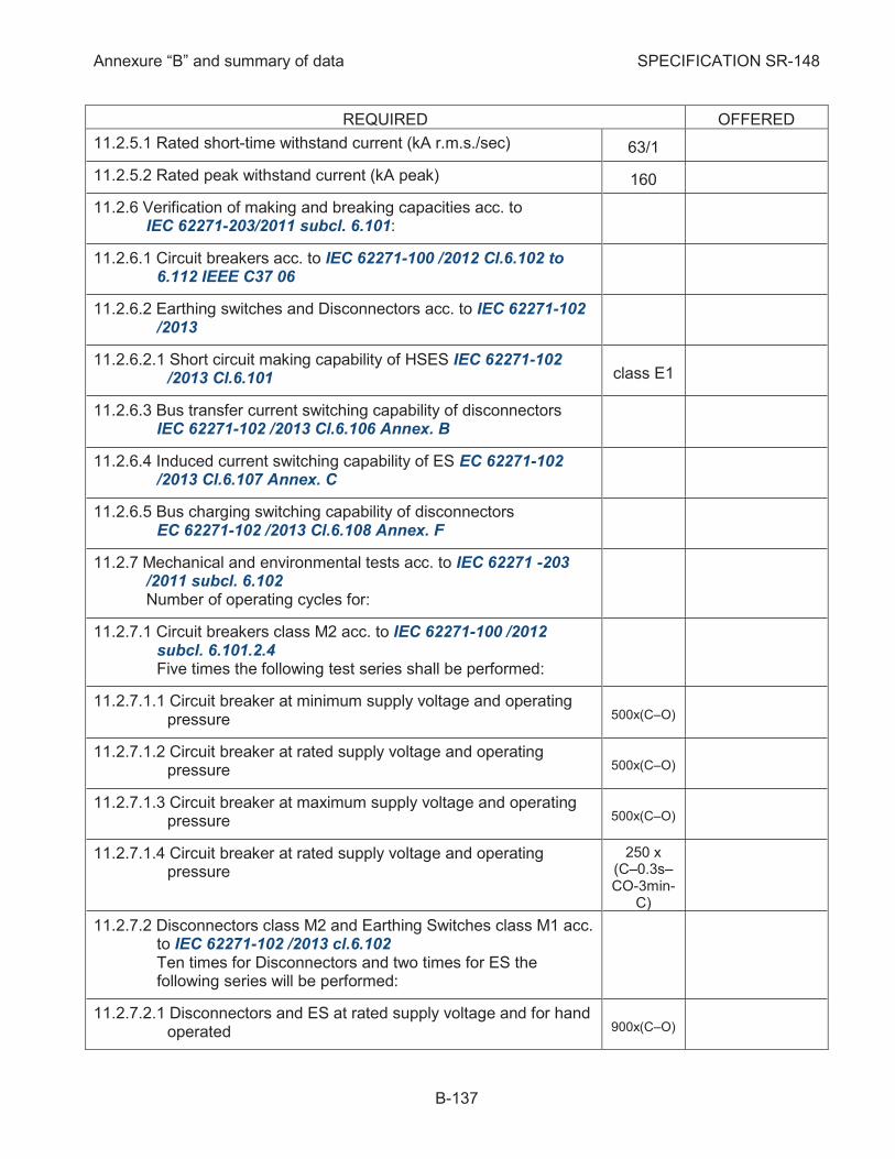
Annexure “B” and summary of data SPECIFICATION SR-148
B-137
REQUIRED OFFERED
11.2.5.1 Rated short-time withstand current (kA r.m.s./sec) 63/1
11.2.5.2 Rated peak withstand current (kA peak) 160
Verification of making and breaking capacities acc. to 11.2.6IEC 62271-203/2011 subcl. 6.101:
11.2.6.1 Circuit breakers acc. to IEC 62271-100 /2012 Cl.6.102 to 6.112 IEEE C37 06
11.2.6.2 Earthing switches and Disconnectors acc. to IEC 62271-102 /2013
11.2.6.2.1 Short circuit making capability of HSES IEC 62271-102 /2013 Cl.6.101 class E1
11.2.6.3 Bus transfer current switching capability of disconnectors IEC 62271-102 /2013 Cl.6.106 Annex. B
11.2.6.4 Induced current switching capability of ES EC 62271-102 /2013 Cl.6.107 Annex. C
11.2.6.5 Bus charging switching capability of disconnectors EC 62271-102 /2013 Cl.6.108 Annex. F
Mechanical and environmental tests acc. to IEC 62271 -203 11.2.7/2011 subcl. 6.102 Number of operating cycles for:
11.2.7.1 Circuit breakers class M2 acc. to IEC 62271-100 /2012 subcl. 6.101.2.4 Five times the following test series shall be performed:
11.2.7.1.1 Circuit breaker at minimum supply voltage and operating pressure 500x(C–O)
11.2.7.1.2 Circuit breaker at rated supply voltage and operating pressure 500x(C–O)
11.2.7.1.3 Circuit breaker at maximum supply voltage and operating pressure 500x(C–O)
11.2.7.1.4 Circuit breaker at rated supply voltage and operating pressure
250 x (C–0.3s–CO-3min-
C)
11.2.7.2 Disconnectors class M2 and Earthing Switches class M1 acc. to IEC 62271-102 /2013 cl.6.102 Ten times for Disconnectors and two times for ES the following series will be performed:
11.2.7.2.1 Disconnectors and ES at rated supply voltage and for hand operated 900x(C–O)

Annexure “B” and summary of data SPECIFICATION SR-148
B-138
REQUIRED OFFERED
11.2.7.2.2 Disconnectors and ES at minimum supply voltage 50x(C–O)
11.2.7.2.3 Disconnectors and ES at maximum supply voltage 50x(C–O)
11.2.7.3 Operation test at limit temperatures acc. to IEC 62271-203/2011 subc. 6.102
11.2.7.3.1 Operation test at high temperature (°C) +50
11.2.7.3.2 Operation test at low temperature (°C) -5
11.2.7.4 Operating time, maximum energy consumption, operation of auxiliary contacts, position indicating device shall be verified
11.2.7.5 The main circuit resistance shall not increase after test more than 20%
11.2.7.6 All other elements comprising interlocks. Contractor shall indicate a list. 50x(C–O)
11.2.7.7 A tightness test shall be performed before and after mechanical endurance test
Electrical endurance testing of CB acc. to IEC 62271-310/2008 11.2.8
Voltage test as condition check, after breaking and mechanical 11.2.9tests acc. to IEC 62271-1 /2011 cl.6.2.11
Verification of degree of protection for auxiliary and control 11.2.10circuits acc. to IEC 62271-203 /2011 subcl.6.7
11.2.10.1 Verification of the IP coding acc. to IEC 60529/2013
11.2.10.2 Mechanical impact test acc. to IEC 62262 /2002 cl.5
Test for support insulators and partitions acc. to IEC 62271 -11.2.11203 /2011 cl.6.104, cl.6.106 and IEEE C37-122 and BS 50089. Please indicate other standards and describe test method.
11.2.11.1 Pressure test on partitions
11.2.11.1.1 Pressure test higher than: Indicate design pressure "p". > 3p
11.2.11.1.2 Thermal performance (on partitions and support insulators)
11.2.11.1.3 Tightness test for partitions
Proof tests for enclosures, acc. to IEC 62271 -203/2012 11.2.12subcl. 6.103
11.2.12.1 Bursting pressure test:
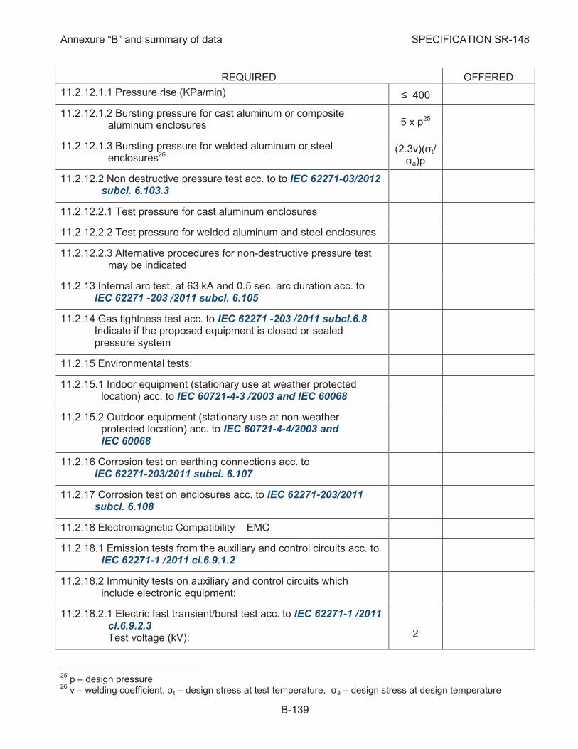
Annexure “B” and summary of data SPECIFICATION SR-148
B-139
REQUIRED OFFERED
11.2.12.1.1 Pressure rise (KPa/min) ≤ 400
11.2.12.1.2 Bursting pressure for cast aluminum or composite aluminum enclosures 5 x p25
11.2.12.1.3 Bursting pressure for welded aluminum or steel enclosures26
(2.3v)(σt/ σa)p
11.2.12.2 Non destructive pressure test acc. to to IEC 62271-03/2012 subcl. 6.103.3
11.2.12.2.1 Test pressure for cast aluminum enclosures
11.2.12.2.2 Test pressure for welded aluminum and steel enclosures
11.2.12.2.3 Alternative procedures for non-destructive pressure test may be indicated
Internal arc test, at 63 kA and 0.5 sec. arc duration acc. to 11.2.13IEC 62271 -203 /2011 subcl. 6.105
Gas tightness test acc. to IEC 62271 -203 /2011 subcl.6.8 11.2.14Indicate if the proposed equipment is closed or sealed pressure system
Environmental tests: 11.2.15
11.2.15.1 Indoor equipment (stationary use at weather protected location) acc. to IEC 60721-4-3 /2003 and IEC 60068
11.2.15.2 Outdoor equipment (stationary use at non-weather protected location) acc. to IEC 60721-4-4/2003 and IEC 60068
Corrosion test on earthing connections acc. to 11.2.16IEC 62271-203/2011 subcl. 6.107
Corrosion test on enclosures acc. to IEC 62271-203/2011 11.2.17subcl. 6.108
Electromagnetic Compatibility – EMC 11.2.18
11.2.18.1 Emission tests from the auxiliary and control circuits acc. to IEC 62271-1 /2011 cl.6.9.1.2
11.2.18.2 Immunity tests on auxiliary and control circuits which include electronic equipment:
11.2.18.2.1 Electric fast transient/burst test acc. to IEC 62271-1 /2011 cl.6.9.2.3 Test voltage (kV):
2
25
p – design pressure 26
v – welding coefficient, σt – design stress at test temperature, σa – design stress at design temperature
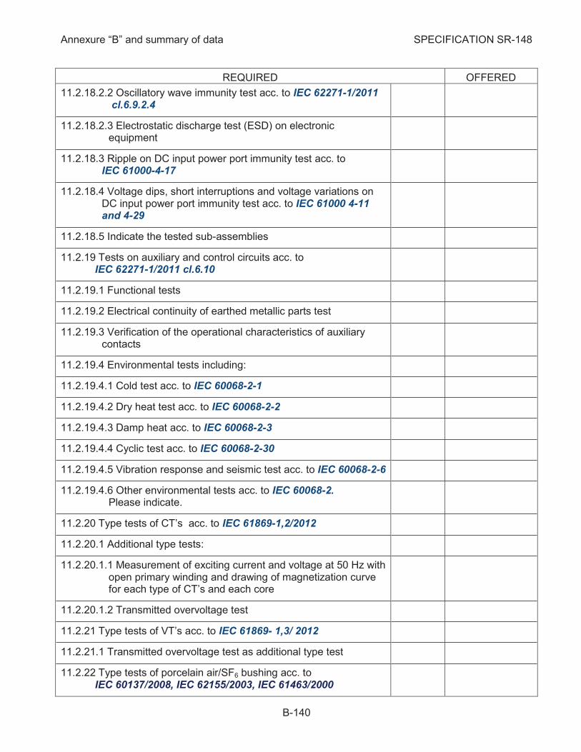
Annexure “B” and summary of data SPECIFICATION SR-148
B-140
REQUIRED OFFERED
11.2.18.2.2 Oscillatory wave immunity test acc. to IEC 62271-1/2011 cl.6.9.2.4
11.2.18.2.3 Electrostatic discharge test (ESD) on electronic equipment
11.2.18.3 Ripple on DC input power port immunity test acc. to IEC 61000-4-17
11.2.18.4 Voltage dips, short interruptions and voltage variations on DC input power port immunity test acc. to IEC 61000 4-11 and 4-29
11.2.18.5 Indicate the tested sub-assemblies
Tests on auxiliary and control circuits acc. to 11.2.19IEC 62271-1/2011 cl.6.10
11.2.19.1 Functional tests
11.2.19.2 Electrical continuity of earthed metallic parts test
11.2.19.3 Verification of the operational characteristics of auxiliary contacts
11.2.19.4 Environmental tests including:
11.2.19.4.1 Cold test acc. to IEC 60068-2-1
11.2.19.4.2 Dry heat test acc. to IEC 60068-2-2
11.2.19.4.3 Damp heat acc. to IEC 60068-2-3
11.2.19.4.4 Cyclic test acc. to IEC 60068-2-30
11.2.19.4.5 Vibration response and seismic test acc. to IEC 60068-2-6
11.2.19.4.6 Other environmental tests acc. to IEC 60068-2. Please indicate.
Type tests of CT’s acc. to IEC 61869-1,2/2012 11.2.20
11.2.20.1 Additional type tests:
11.2.20.1.1 Measurement of exciting current and voltage at 50 Hz with open primary winding and drawing of magnetization curve for each type of CT’s and each core
11.2.20.1.2 Transmitted overvoltage test
Type tests of VT’s acc. to IEC 61869- 1,3/ 2012 11.2.21
11.2.21.1 Transmitted overvoltage test as additional type test
Type tests of porcelain air/SF6 bushing acc. to 11.2.22IEC 60137/2008, IEC 62155/2003, IEC 61463/2000
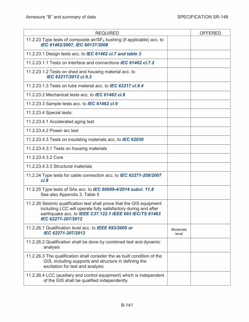
Annexure “B” and summary of data SPECIFICATION SR-148
B-141
REQUIRED OFFERED
Type tests of composite air/SF6 bushing (if applicable) acc. to 11.2.23IEC 61462/2007, IEC 60137/2008
11.2.23.1 Design tests acc. to IEC 61462 cl.7 and table 3
11.2.23.1.1 Tests on interface and connections IEC 61462 cl.7.2
11.2.23.1.2 Tests on shed and housing material acc. to IEC 62217/2012 cl.9.3
11.2.23.1.3 Tests on tube material acc. to IEC 62217 cl.9.4
11.2.23.2 Mechanical tests acc. to IEC 61462 cl.8
11.2.23.3 Sample tests acc. to IEC 61462 cl.9
11.2.23.4 Special tests:
11.2.23.4.1 Accelerated aging test
11.2.23.4.2 Power arc test
11.2.23.4.3 Tests on insulating materials acc. to IEC 62039
11.2.23.4.3.1 Tests on housing materials
11.2.23.4.3.2 Core
11.2.23.4.3.3 Structural materials
Type tests for cable connection acc. to IEC 62271-209/2007 11.2.24cl.8
Type tests of SAs acc. to IEC 60099-4/2014 subcl. 11.8 11.2.25See also Appendix 3, Table 5
Seismic qualification test shall prove that the GIS equipment 11.2.26including LCC will operate fully satisfactory during and after earthquake acc. to IEEE C37.122.1 IEEE 693 IEC/TS 61463 IEC 62271-207/2012
11.2.26.1 Qualification level acc. to IEEE 693/2005 or IEC 62271-207/2012
Moderate level
11.2.26.2 Qualification shall be done by combined test and dynamic analysis
11.2.26.3 The qualification shall consider the as built condition of the GIS, including supports and structure in defining the excitation for test and analysis
11.2.26.4 LCC (auxiliary and control equipment) which is independent of the GIS shall be qualified independently
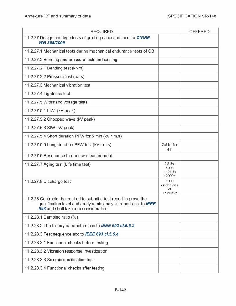
Annexure “B” and summary of data SPECIFICATION SR-148
B-142
REQUIRED OFFERED
Design and type tests of grading capacitors acc. to CIGRE 11.2.27WG 368/2009
11.2.27.1 Mechanical tests during mechanical endurance tests of CB
11.2.27.2 Bending and pressure tests on housing
11.2.27.2.1 Bending test (kNm)
11.2.27.2.2 Pressure test (bars)
11.2.27.3 Mechanical vibration test
11.2.27.4 Tightness test
11.2.27.5 Withstand voltage tests:
11.2.27.5.1 LIW (kV peak)
11.2.27.5.2 Chopped wave (kV peak)
11.2.27.5.3 SIW (kV peak)
11.2.27.5.4 Short duration PFW for 5 min (kV r.m.s)
11.2.27.5.5 Long duration PFW test (kV r.m.s) 2xUn for 8 h
11.2.27.6 Resonance frequency measurement
11.2.27.7 Aging test (Life time test) 2.3Un-500h
or 2xUn 10000h
11.2.27.8 Discharge test 1000 discharges
at 1.5xUn√2
Contractor is required to submit a test report to prove the 11.2.28qualification level and an dynamic analysis report acc. to IEEE 693 and shall take into consideration:
11.2.28.1 Damping ratio (%)
11.2.28.2 The history parameters acc.to IEEE 693 cl.5.5.2
11.2.28.3 Test sequence acc.to IEEE 693 cl.5.5.4
11.2.28.3.1 Functional checks before testing
11.2.28.3.2 Vibration response investigation
11.2.28.3.3 Seismic qualification test
11.2.28.3.4 Functional checks after testing
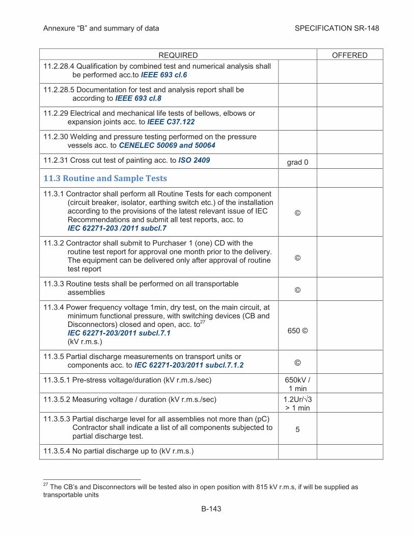
Annexure “B” and summary of data SPECIFICATION SR-148
B-143
REQUIRED OFFERED
11.2.28.4 Qualification by combined test and numerical analysis shall be performed acc.to IEEE 693 cl.6
11.2.28.5 Documentation for test and analysis report shall be according to IEEE 693 cl.8
Electrical and mechanical life tests of bellows, elbows or 11.2.29expansion joints acc. to IEEE C37.122
Welding and pressure testing performed on the pressure 11.2.30vessels acc. to CENELEC 50069 and 50064
Cross cut test of painting acc. to ISO 2409 11.2.31 grad 0
11.3 Routine and Sample Tests
Contractor shall perform all Routine Tests for each component 11.3.1(circuit breaker, isolator, earthing switch etc.) of the installation according to the provisions of the latest relevant issue of IEC Recommendations and submit all test reports, acc. to IEC 62271-203 /2011 subcl.7
©
Contractor shall submit to Purchaser 1 (one) CD with the 11.3.2routine test report for approval one month prior to the delivery. The equipment can be delivered only after approval of routine test report
©
Routine tests shall be performed on all transportable 11.3.3assemblies ©
Power frequency voltage 1min, dry test, on the main circuit, at 11.3.4minimum functional pressure, with switching devices (CB and Disconnectors) closed and open, acc. to27 IEC 62271-203/2011 subcl.7.1 (kV r.m.s.)
650 ©
Partial discharge measurements on transport units or 11.3.5components acc. to IEC 62271-203/2011 subcl.7.1.2 ©
11.3.5.1 Pre-stress voltage/duration (kV r.m.s./sec) 650kV / 1 min
11.3.5.2 Measuring voltage / duration (kV r.m.s./sec) 1.2Ur/√3 > 1 min
11.3.5.3 Partial discharge level for all assemblies not more than (pC) Contractor shall indicate a list of all components subjected to partial discharge test.
5
11.3.5.4 No partial discharge up to (kV r.m.s.)
27
The CB’s and Disconnectors will be tested also in open position with 815 kV r.m.s, if will be supplied as transportable units

Annexure “B” and summary of data SPECIFICATION SR-148
B-144
REQUIRED OFFERED
11.3.5.5 Extinction voltage (kV r.m.s.)
Voltage tests (1 s) for the auxiliary and control circuits, acc. to 11.3.6IEC 62271-203/2011 subcl.7.2 (kV r.m.s.)
1ã
Measurement of the resistance of the main circuits, acc. to 11.3.7IEC 62271-203/2011 subcl.7.3 Overall resistance on transport units measured with the equipment in closed position (ohm)28
≤ 1.2 Ru
ã
Gas tightness tests acc. to IEC 62271-203/2011 subcl.7.4 11.3.8 ã
Visual check, verification of design and checking of nameplate, 11.3.9in order to prove the compliance with Specification SR-148 acc. to IEC 62271 -203 /2011 subcl.7.5
ã
Pressure tests of enclosures acc. to IEC 62271-203/2011 11.3.10subcl.7.101 ã
11.3.10.1 Welded aluminum/steel enclosures (bar) 1.3 x p / ≥ 1min29
11.3.10.2 Cast aluminum and composite aluminum enclosures (bar) 2 x p / ≥ 1min
Mechanical operation tests, acc. to IEC 62271-203/2011 11.3.11subcl.7.102 Number of operating cycles for:
ã
11.3.11.1 Circuit breaker at:
11.3.11.1.1 Rated supply voltage and rated pressure for operation (if applicable)
5 x (C-O) 5 x (O-to-C)
to=0.3 s
11.3.11.1.2 Minimum supply voltage and minimum pressure for operation (if applicable)
5 x C 5 x O
11.3.11.1.3 Maximum supply voltage and maximum pressure for operation (if applicable)
5 x C 5 x O
11.3.11.1.4 The SF6 pressure and pressure of operating mechanism (if applicable), operating times and mechanical travel characteristics shall be noted during the test
11.3.11.2 Disconnectors and Earthing Switches at:
11.3.11.2.1 Rated supply voltage 5 x (C-O)
28
Ru = Sum of the resistance of relevant components (CB, Disconnectors, etc) during the type test 29
p = design pressure of enclosure
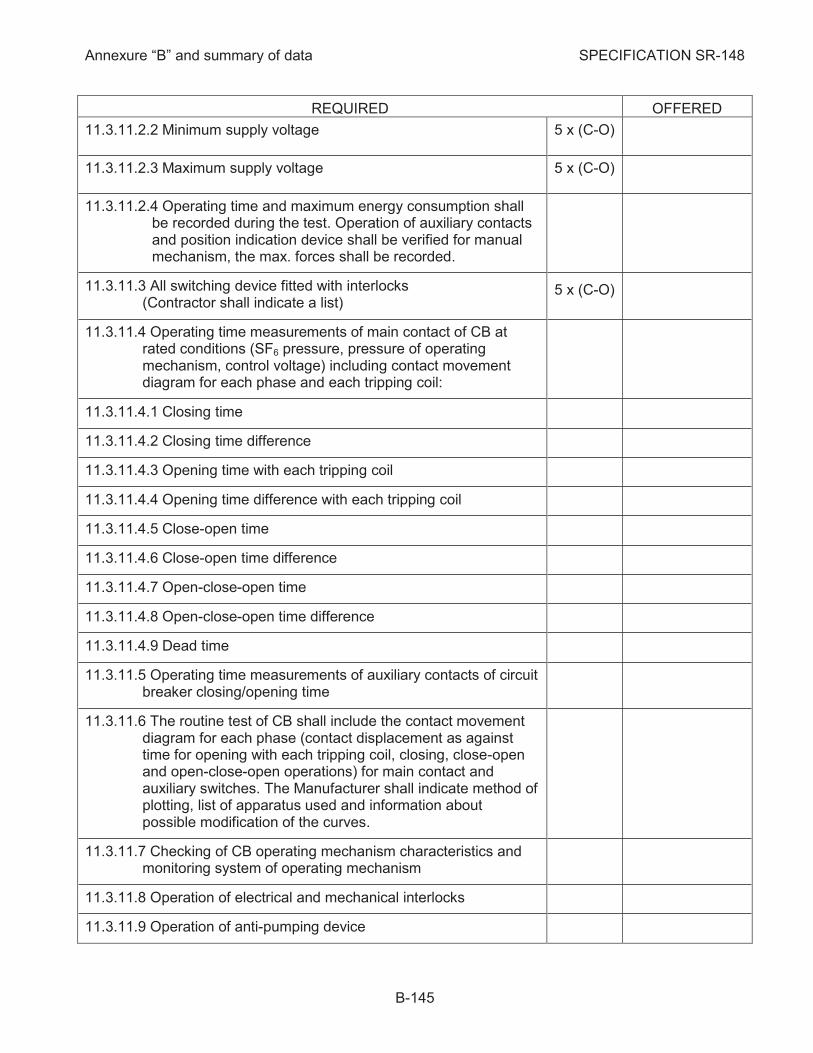
Annexure “B” and summary of data SPECIFICATION SR-148
B-145
REQUIRED OFFERED
11.3.11.2.2 Minimum supply voltage 5 x (C-O)
11.3.11.2.3 Maximum supply voltage 5 x (C-O)
11.3.11.2.4 Operating time and maximum energy consumption shall be recorded during the test. Operation of auxiliary contacts and position indication device shall be verified for manual mechanism, the max. forces shall be recorded.
11.3.11.3 All switching device fitted with interlocks (Contractor shall indicate a list)
5 x (C-O)
11.3.11.4 Operating time measurements of main contact of CB at rated conditions (SF6 pressure, pressure of operating mechanism, control voltage) including contact movement diagram for each phase and each tripping coil:
11.3.11.4.1 Closing time
11.3.11.4.2 Closing time difference
11.3.11.4.3 Opening time with each tripping coil
11.3.11.4.4 Opening time difference with each tripping coil
11.3.11.4.5 Close-open time
11.3.11.4.6 Close-open time difference
11.3.11.4.7 Open-close-open time
11.3.11.4.8 Open-close-open time difference
11.3.11.4.9 Dead time
11.3.11.5 Operating time measurements of auxiliary contacts of circuit breaker closing/opening time
11.3.11.6 The routine test of CB shall include the contact movement diagram for each phase (contact displacement as against time for opening with each tripping coil, closing, close-open and open-close-open operations) for main contact and auxiliary switches. The Manufacturer shall indicate method of plotting, list of apparatus used and information about possible modification of the curves.
11.3.11.7 Checking of CB operating mechanism characteristics and monitoring system of operating mechanism
11.3.11.8 Operation of electrical and mechanical interlocks
11.3.11.9 Operation of anti-pumping device

Annexure “B” and summary of data SPECIFICATION SR-148
B-146
REQUIRED OFFERED
Tests of auxiliary circuits, equipment and interlocks in the 11.3.12control mechanisms acc. to IEC 62271-203/2011 subcl.7.103 ã
Tests on auxiliary and control circuits acc. to 11.3.13IEC 62271-1/2011 subcl.7.2 shall include: ã
11.3.13.1 Inspection and verification of conformity to the circuit diagrams and wiring diagrams
11.3.13.2 Functional tests
11.3.13.3 Verification of protection against electrical shock
11.3.13.4 Verification of the electrical continuity of earthed metallic parts (if not possible only visual inspection)
Routine tests of partitions and support insulators acc. to 11.3.14IEC 62271-203/2011 cl.7.104 and BS 50089 ã
11.3.14.1 Power frequency voltage test (kV r.m.s.)
11.3.14.2 Visual inspection
11.3.14.3 Nondestructive examination (indicate method)
11.3.14.4 Partial discharge test
11.3.14.5 Pressure test Indicate also the design pressure (bar).
2 x design pressure,
1min
11.3.14.6 Production consistency pressure test acc. to BS 50089 cl.7.2.5
11.3.14.7 Permissible leakage rate Fp (%)
Welding and pressure testing performed on the pressure 11.3.15vessels shall be according to CENELEC EN 50 052 (cast) CENELEC EN 50 064 and EN 50069 (welded)
ã
LCC tests acc. to IEC 61439-1/2009 IEC60439-1/2004 11.3.16IEC60204-1/2005 IEC 60255-3/1992 ã
The digital interfaces based on IEC 61850 shall be tested acc. 11.3.17to IEC 62271-3 cl. 8 ã
Check of the pick-up values of the pressure and density of 11.3.18SF6 gas monitoring ©
Check of pressure relief device 11.3.19 ©
UHF coupler test 11.3.20 ©
Measurement of heater resistance 11.3.21 ©
Resistance measurement of control coils of CB 11.3.22 ©
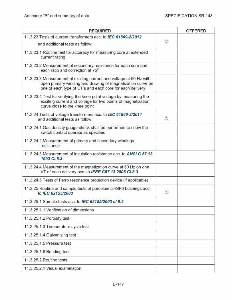
Annexure “B” and summary of data SPECIFICATION SR-148
B-147
REQUIRED OFFERED
Tests of current transformers acc. to IEC 61869-2/2012 11.3.23
and additional tests as follow: ã
11.3.23.1 Routine test for accuracy for measuring core at extended current rating
11.3.23.2 Measurement of secondary resistance for each core and each ratio and correction at 750
11.3.23.3 Measurement of exciting current and voltage at 50 Hz with open primary winding and drawing of magnetization curve on one of each type of CT’s and each core for each delivery
11.3.23.4 Test for verifying the knee point voltage by measuring the exciting current and voltage for two points of magnetization curve close to the knee point
Tests of voltage transformers acc. to IEC 61869-3/2011 11.3.24and additional tests as follow: ã
11.3.24.1 Gas density gauge check shall be performed to show the switch contact operate as specified
11.3.24.2 Measurement of primary and secondary windings resistance
11.3.24.3 Measurement of insulation resistance acc. to ANSI C 57.13 1993 Cl.8.3
11.3.24.4 Measurement of the magnetization curve at 50 Hz on one VT of each delivery acc. to IEEE C57.13 2008 Cl.8.3
11.3.24.5 Tests of Ferro resonance protection device (if applicable)
Routine and sample tests of porcelain air/SF6 bushings acc. 11.3.25to IEC 62155/2003 ã
11.3.25.1 Sample tests acc. to IEC 62155/2003 cl.9.2
11.3.25.1.1 Verification of dimensions
11.3.25.1.2 Porosity test
11.3.25.1.3 Temperature cycle test
11.3.25.1.4 Galvanizing test
11.3.25.1.5 Pressure test
11.3.25.1.6 Bending test
11.3.25.2 Routine tests
11.3.25.2.1 Visual examination
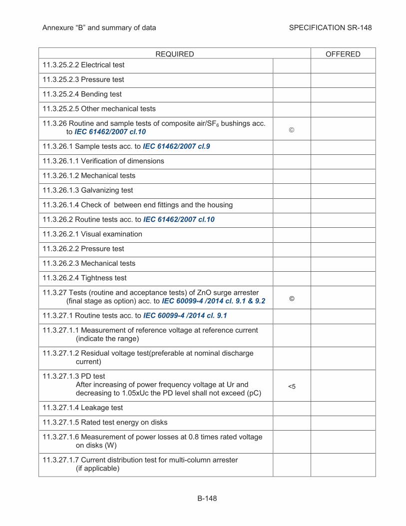
Annexure “B” and summary of data SPECIFICATION SR-148
B-148
REQUIRED OFFERED
11.3.25.2.2 Electrical test
11.3.25.2.3 Pressure test
11.3.25.2.4 Bending test
11.3.25.2.5 Other mechanical tests
Routine and sample tests of composite air/SF6 bushings acc. 11.3.26to IEC 61462/2007 cl.10 ã
11.3.26.1 Sample tests acc. to IEC 61462/2007 cl.9
11.3.26.1.1 Verification of dimensions
11.3.26.1.2 Mechanical tests
11.3.26.1.3 Galvanizing test
11.3.26.1.4 Check of between end fittings and the housing
11.3.26.2 Routine tests acc. to IEC 61462/2007 cl.10
11.3.26.2.1 Visual examination
11.3.26.2.2 Pressure test
11.3.26.2.3 Mechanical tests
11.3.26.2.4 Tightness test
Tests (routine and acceptance tests) of ZnO surge arrester 11.3.27(final stage as option) acc. to IEC 60099-4 /2014 cl. 9.1 & 9.2 ©
11.3.27.1 Routine tests acc. to IEC 60099-4 /2014 cl. 9.1
11.3.27.1.1 Measurement of reference voltage at reference current (indicate the range)
11.3.27.1.2 Residual voltage test(preferable at nominal discharge current)
11.3.27.1.3 PD test After increasing of power frequency voltage at Ur and decreasing to 1.05xUc the PD level shall not exceed (pC)
<5
11.3.27.1.4 Leakage test
11.3.27.1.5 Rated test energy on disks
11.3.27.1.6 Measurement of power losses at 0.8 times rated voltage on disks (W)
11.3.27.1.7 Current distribution test for multi-column arrester (if applicable)
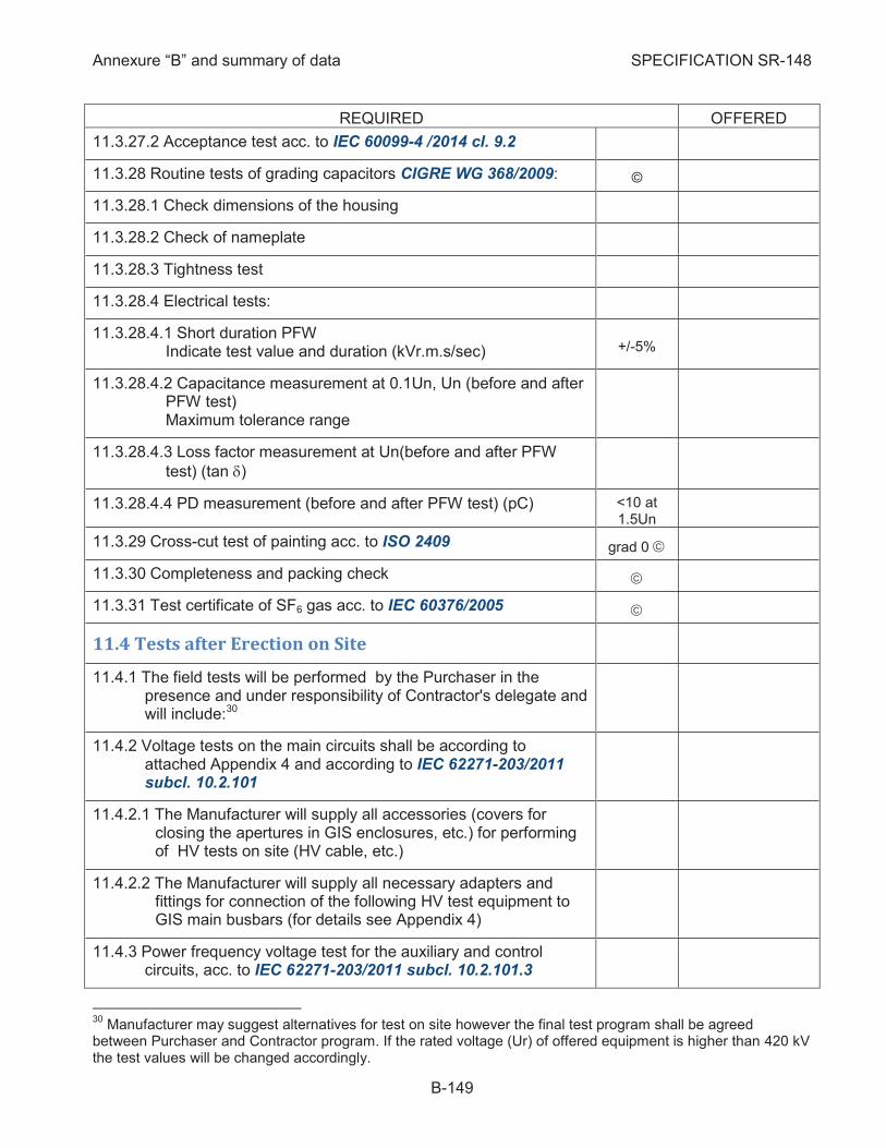
Annexure “B” and summary of data SPECIFICATION SR-148
B-149
REQUIRED OFFERED
11.3.27.2 Acceptance test acc. to IEC 60099-4 /2014 cl. 9.2
Routine tests of grading capacitors CIGRE WG 368/2009: 11.3.28 ©
11.3.28.1 Check dimensions of the housing
11.3.28.2 Check of nameplate
11.3.28.3 Tightness test
11.3.28.4 Electrical tests:
11.3.28.4.1 Short duration PFW Indicate test value and duration (kVr.m.s/sec) +/-5%
11.3.28.4.2 Capacitance measurement at 0.1Un, Un (before and after PFW test) Maximum tolerance range
11.3.28.4.3 Loss factor measurement at Un(before and after PFW
test) (tan d)
11.3.28.4.4 PD measurement (before and after PFW test) (pC) <10 at 1.5Un
Cross-cut test of painting acc. to ISO 2409 11.3.29 grad 0 ã
Completeness and packing check 11.3.30 ã
Test certificate of SF6 gas acc. to IEC 60376/2005 11.3.31 ã
11.4 Tests after Erection on Site
The field tests will be performed by the Purchaser in the 11.4.1presence and under responsibility of Contractor's delegate and will include:30
Voltage tests on the main circuits shall be according to 11.4.2attached Appendix 4 and according to IEC 62271-203/2011 subcl. 10.2.101
11.4.2.1 The Manufacturer will supply all accessories (covers for closing the apertures in GIS enclosures, etc.) for performing of HV tests on site (HV cable, etc.)
11.4.2.2 The Manufacturer will supply all necessary adapters and fittings for connection of the following HV test equipment to GIS main busbars (for details see Appendix 4)
Power frequency voltage test for the auxiliary and control 11.4.3circuits, acc. to IEC 62271-203/2011 subcl. 10.2.101.3
30
Manufacturer may suggest alternatives for test on site however the final test program shall be agreed between Purchaser and Contractor program. If the rated voltage (Ur) of offered equipment is higher than 420 kV the test values will be changed accordingly.
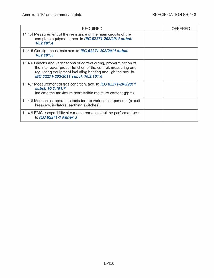
Annexure “B” and summary of data SPECIFICATION SR-148
B-150
REQUIRED OFFERED
Measurement of the resistance of the main circuits of the 11.4.4complete equipment, acc. to IEC 62271-203/2011 subcl. 10.2.101.4
Gas tightness tests acc. to IEC 62271-203/2011 subcl. 11.4.510.2.101.5
Checks and verifications of correct wiring, proper function of 11.4.6the interlocks, proper function of the control, measuring and regulating equipment including heating and lighting acc. to IEC 62271-203/2011 subcl. 10.2.101.6
Measurement of gas condition, acc. to IEC 62271-203/2011 11.4.7subcl. 10.2.101.7 Indicate the maximum permissible moisture content (ppm).
Mechanical operation tests for the various components (circuit 11.4.8breakers, isolators, earthing switches)
EMC compatibility site measurements shall be performed acc. 11.4.9to IEC 62271-1 Annex J
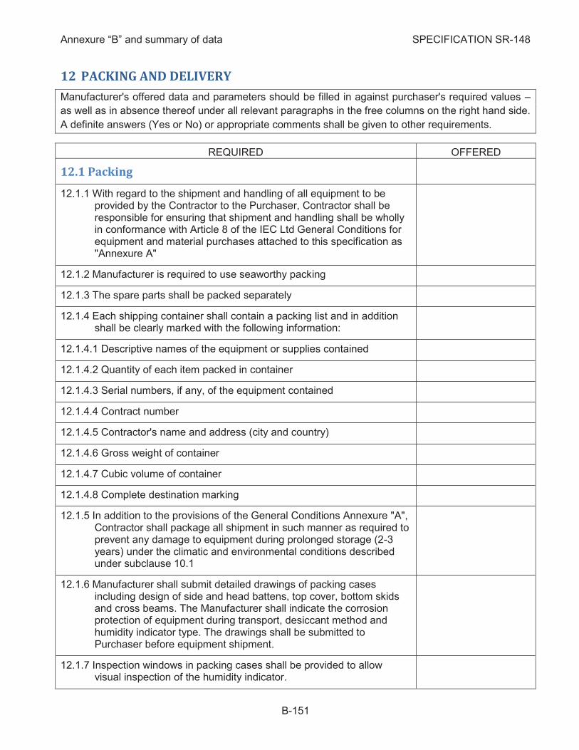
Annexure “B” and summary of data SPECIFICATION SR-148
B-151
12 PACKING AND DELIVERY
Manufacturer's offered data and parameters should be filled in against purchaser's required values –
as well as in absence thereof under all relevant paragraphs in the free columns on the right hand side.
A definite answers (Yes or No) or appropriate comments shall be given to other requirements.
REQUIRED OFFERED
12.1 Packing
With regard to the shipment and handling of all equipment to be 12.1.1provided by the Contractor to the Purchaser, Contractor shall be responsible for ensuring that shipment and handling shall be wholly in conformance with Article 8 of the IEC Ltd General Conditions for equipment and material purchases attached to this specification as "Annexure A"
Manufacturer is required to use seaworthy packing 12.1.2
The spare parts shall be packed separately 12.1.3
Each shipping container shall contain a packing list and in addition 12.1.4shall be clearly marked with the following information:
12.1.4.1 Descriptive names of the equipment or supplies contained
12.1.4.2 Quantity of each item packed in container
12.1.4.3 Serial numbers, if any, of the equipment contained
12.1.4.4 Contract number
12.1.4.5 Contractor's name and address (city and country)
12.1.4.6 Gross weight of container
12.1.4.7 Cubic volume of container
12.1.4.8 Complete destination marking
In addition to the provisions of the General Conditions Annexure "A", 12.1.5Contractor shall package all shipment in such manner as required to prevent any damage to equipment during prolonged storage (2-3 years) under the climatic and environmental conditions described under subclause 10.1
Manufacturer shall submit detailed drawings of packing cases 12.1.6including design of side and head battens, top cover, bottom skids and cross beams. The Manufacturer shall indicate the corrosion protection of equipment during transport, desiccant method and humidity indicator type. The drawings shall be submitted to Purchaser before equipment shipment.
Inspection windows in packing cases shall be provided to allow 12.1.7visual inspection of the humidity indicator.
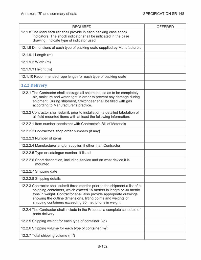
Annexure “B” and summary of data SPECIFICATION SR-148
B-152
REQUIRED OFFERED
The Manufacturer shall provide in each packing case shock 12.1.8indicators. The shock indicator shall be indicated in the case drawing. Indicate type of indicator used
Dimensions of each type of packing crate supplied by Manufacturer: 12.1.9
12.1.9.1 Length (m)
12.1.9.2 Width (m)
12.1.9.3 Height (m)
Recommended rope length for each type of packing crate 12.1.10
12.2 Delivery
The Contractor shall package all shipments so as to be completely 12.2.1air, moisture and water tight in order to prevent any damage during shipment. During shipment, Switchgear shall be filled with gas according to Manufacturer's practice.
Contractor shall submit, prior to installation, a detailed tabulation of 12.2.2all field mounted items with at least the following information:
12.2.2.1 Item number consistent with Contractor's Bill of Materials
12.2.2.2 Contractor's shop order numbers (if any)
12.2.2.3 Number of items
12.2.2.4 Manufacturer and/or supplier, if other than Contractor
12.2.2.5 Type or catalogue number, if listed
12.2.2.6 Short description, including service and on what device it is mounted
12.2.2.7 Shipping date
12.2.2.8 Shipping details
Contractor shall submit three months prior to the shipment a list of all 12.2.3shipping containers, which exceed 15 meters in length or 30 metric tons in weight. Contractor shall also provide appropriate drawings showing the outline dimensions, lifting points and weights of shipping containers exceeding 30 metric tons in weight
The Contractor shall include in the Proposal a complete schedule of 12.2.4parts delivery
Shipping weight for each type of container (kg) 12.2.5
Shipping volume for each type of container (m3) 12.2.6
Total shipping volume (m3) 12.2.7

Annexure “B” and summary of data SPECIFICATION SR-148
B-153
REQUIRED OFFERED
Contractor shall supply three (3) months before the shipment of the 12.2.8equipment two (2) sets of the complete Bill of Materials to enable checking and identifying of the equipment upon receipt of the same
Contractor shall mail before shipment of the equipment one (1) copy 12.2.9of the relevant test reports and one (1) copy of the ship inspections report
The Contractor shall include a Bill of Materials with the shipment to 12.2.10enable the Purchaser to determine if all disassembled items have been received
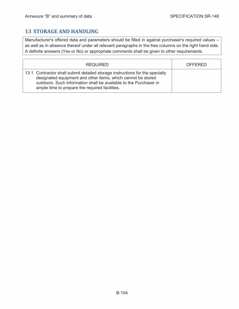
Annexure “B” and summary of data SPECIFICATION SR-148
B-154
13 STORAGE AND HANDLING
Manufacturer's offered data and parameters should be filled in against purchaser's required values –
as well as in absence thereof under all relevant paragraphs in the free columns on the right hand side.
A definite answers (Yes or No) or appropriate comments shall be given to other requirements.
REQUIRED OFFERED
13.1 Contractor shall submit detailed storage instructions for the specially designated equipment and other items, which cannot be stored outdoors. Such information shall be available to the Purchaser in ample time to prepare the required facilities.
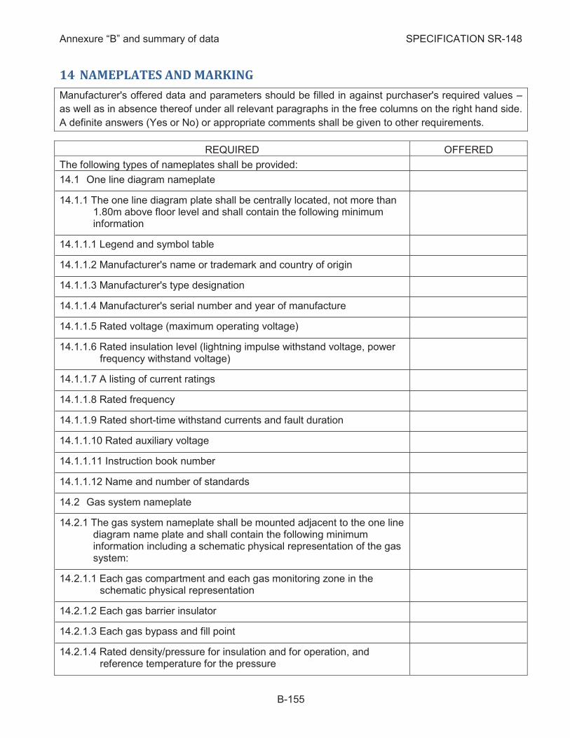
Annexure “B” and summary of data SPECIFICATION SR-148
B-155
14 NAMEPLATES AND MARKING
Manufacturer's offered data and parameters should be filled in against purchaser's required values –
as well as in absence thereof under all relevant paragraphs in the free columns on the right hand side.
A definite answers (Yes or No) or appropriate comments shall be given to other requirements.
REQUIRED OFFERED
The following types of nameplates shall be provided:
14.1 One line diagram nameplate
The one line diagram plate shall be centrally located, not more than 14.1.11.80m above floor level and shall contain the following minimum information
14.1.1.1 Legend and symbol table
14.1.1.2 Manufacturer's name or trademark and country of origin
14.1.1.3 Manufacturer's type designation
14.1.1.4 Manufacturer's serial number and year of manufacture
14.1.1.5 Rated voltage (maximum operating voltage)
14.1.1.6 Rated insulation level (lightning impulse withstand voltage, power frequency withstand voltage)
14.1.1.7 A listing of current ratings
14.1.1.8 Rated frequency
14.1.1.9 Rated short-time withstand currents and fault duration
14.1.1.10 Rated auxiliary voltage
14.1.1.11 Instruction book number
14.1.1.12 Name and number of standards
14.2 Gas system nameplate
The gas system nameplate shall be mounted adjacent to the one line 14.2.1diagram name plate and shall contain the following minimum information including a schematic physical representation of the gas system:
14.2.1.1 Each gas compartment and each gas monitoring zone in the schematic physical representation
14.2.1.2 Each gas barrier insulator
14.2.1.3 Each gas bypass and fill point
14.2.1.4 Rated density/pressure for insulation and for operation, and reference temperature for the pressure
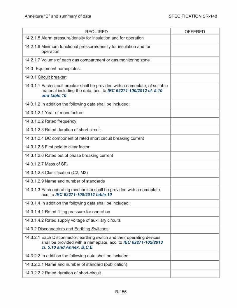
Annexure “B” and summary of data SPECIFICATION SR-148
B-156
REQUIRED OFFERED
14.2.1.5 Alarm pressure/density for insulation and for operation
14.2.1.6 Minimum functional pressure/density for insulation and for operation
14.2.1.7 Volume of each gas compartment or gas monitoring zone
14.3 Equipment nameplates:
Circuit breaker: 14.3.1
14.3.1.1 Each circuit breaker shall be provided with a nameplate, of suitable material including the data, acc. to IEC 62271-100/2012 cl. 5.10 and table 10
14.3.1.2 In addition the following data shall be included:
14.3.1.2.1 Year of manufacture
14.3.1.2.2 Rated frequency
14.3.1.2.3 Rated duration of short circuit
14.3.1.2.4 DC component of rated short circuit breaking current
14.3.1.2.5 First pole to clear factor
14.3.1.2.6 Rated out of phase breaking current
14.3.1.2.7 Mass of SF6
14.3.1.2.8 Classification (C2, M2)
14.3.1.2.9 Name and number of standards
14.3.1.3 Each operating mechanism shall be provided with a nameplate acc. to IEC 62271-100/2012 table 10
14.3.1.4 In addition the following data shall be included:
14.3.1.4.1 Rated filling pressure for operation
14.3.1.4.2 Rated supply voltage of auxiliary circuits
Disconnectors and Earthing Switches: 14.3.2
14.3.2.1 Each Disconnector, earthing switch and their operating devices shall be provided with a nameplate, acc. to IEC 62271-102/2013 cl. 5.10 and Annex. B,C,E
14.3.2.2 In addition the following data shall be included:
14.3.2.2.1 Name and number of standard (publication)
14.3.2.2.2 Rated duration of short-circuit
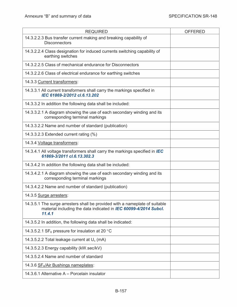
Annexure “B” and summary of data SPECIFICATION SR-148
B-157
REQUIRED OFFERED
14.3.2.2.3 Bus transfer current making and breaking capability of Disconnectors
14.3.2.2.4 Class designation for induced currents switching capability of earthing switches
14.3.2.2.5 Class of mechanical endurance for Disconnectors
14.3.2.2.6 Class of electrical endurance for earthing switches
Current transformers: 14.3.3
14.3.3.1 All current transformers shall carry the markings specified in IEC 61869-2/2012 cl.6.13.202
14.3.3.2 In addition the following data shall be included:
14.3.3.2.1 A diagram showing the use of each secondary winding and its corresponding terminal markings
14.3.3.2.2 Name and number of standard (publication)
14.3.3.2.3 Extended current rating (%)
Voltage transformers: 14.3.4
14.3.4.1 All voltage transformers shall carry the markings specified in IEC 61869-3/2011 cl.6.13.302.3
14.3.4.2 In addition the following data shall be included:
14.3.4.2.1 A diagram showing the use of each secondary winding and its corresponding terminal markings
14.3.4.2.2 Name and number of standard (publication)
Surge arresters: 14.3.5
14.3.5.1 The surge arresters shall be provided with a nameplate of suitable material including the data indicated in IEC 60099-4/2014 Subcl. 11.4.1
14.3.5.2 In addition, the following data shall be indicated:
14.3.5.2.1 SF6 pressure for insulation at 20 °C
14.3.5.2.2 Total leakage current at Uc (mA)
14.3.5.2.3 Energy capability (kW.sec/kV)
14.3.5.2.4 Name and number of standard
SF6/Air Bushings nameplates: 14.3.6
14.3.6.1 Alternative A – Porcelain insulator

Annexure “B” and summary of data SPECIFICATION SR-148
B-158
REQUIRED OFFERED
14.3.6.1.1 Nameplate acc.to IEC 60137/2008
14.3.6.1.2 In addition the following data shall be included:
14.3.6.1.2.1 Rated (1 sec) short-time current
14.3.6.1.2.2 Creepage distance
14.3.6.1.2.3 Rated SF6 density/ pressure and reference temperature for the pressure
14.3.6.1.2.4 Maximum operating SF6 gas pressure and minimum dielectric density/pressure
14.3.6.1.2.5 Cantilever withstand service load
14.3.6.2 Alternative 2 – composite insulator
14.3.6.2.1 Nameplate acc. to IEC 60137/2008
14.3.6.2.2 In addition the following data shall be included:
14.3.6.2.2.1 Rated (1 sec) short-time current
14.3.6.2.2.2 Creepage distance
14.3.6.2.2.3 Rated pressure and reference temperature for the pressure
14.3.6.2.2.4 Maximum mechanical load (MML)
Dry Type Cable connection: 14.3.7
14.3.7.1 The nameplate shall be according to IEC 62271-209/2007
14.4 General Requirements:
The nameplates shall be written in English, with metric units, with all 14.4.1symbols in accordance with the latest IEC Recommendations
The nameplate material shall be no corrosive stainless steel and 14.4.2they shall be mounted with no corrosive type stainless steel screws, bolts or rivets. Mounting of the nameplates with adhesive is not acceptable.
The nameplates shall be engraved by laser 14.4.3
Equipment nameplates shall contain the information required in this 14.4.4Specification for each type of equipment
Phases of each GIS bay shall be identified with phase referencing 14.4.5
Each density/pressure sensor shall be provided with a label 14.4.6identifying the parameter it is reading
Each valve carries a label identifying its gas zone 14.4.7
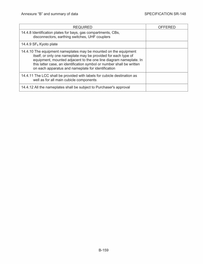
Annexure “B” and summary of data SPECIFICATION SR-148
B-159
REQUIRED OFFERED
Identification plates for bays, gas compartments, CBs, 14.4.8disconnectors, earthing switches, UHF couplers
SF6 Kyoto plate 14.4.9
The equipment nameplates may be mounted on the equipment 14.4.10itself, or only one nameplate may be provided for each type of equipment, mounted adjacent to the one line diagram nameplate. In this latter case, an identification symbol or number shall be written on each apparatus and nameplate for identification
The LCC shall be provided with labels for cubicle destination as 14.4.11well as for all main cubicle components
All the nameplates shall be subject to Purchaser's approval 14.4.12

Annexure “B” and summary of data SPECIFICATION SR-148
B-160
15 NOTES
15.1 General Terms and Conditions
The list of subcontractors shall be approved by Purchaser. 15.1.1
The missing type tests will be performed in a neutral laboratory approved by Purchaser, 15.1.2according to Specification SR-148 in presence of Purchaser's representatives.
The GIS bays can be supplied only after approval of all type and routine test reports. 15.1.3
The equipment type tested cannot be used in GIS bays which will be supplied to Purchaser. 15.1.4
The terminology used in this Specification, is, except where otherwise indicated, in accordance 15.1.5with lasted IEC Publication 62271-203.
The switchgear shall be designed for indoor installation, except the outgoing ducts and 15.1.6associated steel works and outdoor bushings which shall be designed for outdoor installation.
The switchgears shall be of modular design with segregated phases, and as such, shall offer 15.1.7maximum flexibility from the point of view of design, operation, maintenance, extension.
Delivery date is limited to 12 months from placing of the order 15.1.8
The Option 1 shall be valid 5 (five) years from signature of the Contract 15.1.9
The Option 2 shall be valid 7 (seven) years from signature of the Contract 15.1.10
The delivery of options shall be limited to 12 months after placing the order for the option. 15.1.11
The Contractor shall include in Annexure "C" the prices for the basic scope and options. 15.1.12
15.2 Evaluation of Contractor's Technical Proposal
Contractor’s offered data and parameters contained in its offer, as well as definite answers or 15.2.1comments will be evaluated from technical point of view using an expert computer program for decision making.
The decision making process consist of identifying all relevant criteria and attaching to each 15.2.2criterion an appropriate weight for technical evaluation.
All proposals (alternatives) will be evaluated taking into account the same relevant criteria. 15.2.3
The computer program uses a pair wise comparison technique based on statistical analysis to 15.2.4evaluate criteria importance and to rank alternatives (proposals).
The main criteria used for the technical evaluation are according to the main paragraphs in this 15.2.5Specification as follows: Electrical Data, Design and Construction, Tests Requirements, RAM & Maintenance Requirements, Operating Experience (in the world and in Israel), Technical support from Contractor. All sub clauses for which different contractors offer different technical data will form the sub-criteria of the relevant main criteria.
All sub clauses in this Specification indicated by the symbol ã are compulsory requirements. 15.2.6The Bidder's proposal will be almost certainly disqualified, whether the proposal clauses will not comply with one of the compulsory requirements. The compliance with compulsory requirements will be enough, but not limited to, for the offer qualification. Bidder's proposal will be disqualified, if his proposal will not meet the major requirements according to "good engineering" usage for the relevant technology.

Annexure “B” and summary of data SPECIFICATION SR-148
B-161
15.3 Comments by Manufacturer on Annexure “B” and Summary Data

Annexure “B” and summary of data SPECIFICATION SR-148
B-162
15.4 Deviations from Requirements
Manufacturer is invited to describe or indicate deviations of the equipment and accessories from all
requirements in this Specification.
In case no deviations are mentioned it will be understood that Manufacturer’s offer entirely complies with all requirements in this Specification.

Annexure “B” and summary of data SPECIFICATION SR-148
B-163
15.5 Conformity with Proposal Documents
Contractor hereby certifies he agrees to all provisions of the Proposal Documents unless 15.5.1exceptions are specifically and clearly listed in the proposal and identified as Exceptions
Contractor printed terms and conditions are not considered specific exceptions. Any 15.5.2exceptions which Contractor has taken are listed on page 162.
Contractor hereby certifies that he agree to all conditions of the cover letter of the Israel 15.5.3Electric Corporation Limited which accompanied the Proposal Documents
Signature of Contractor
Print name and the title of signing officer
Date of Proposal
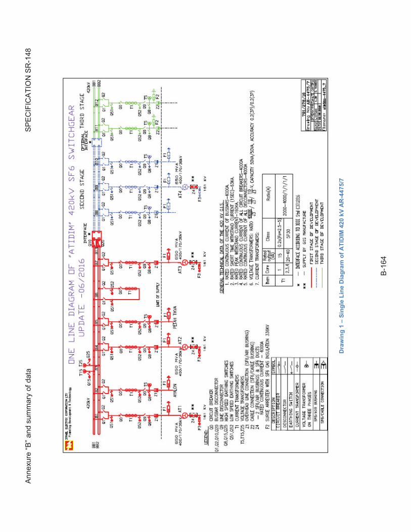
Ann
exur
e “B
” an
d su
mm
ary
of d
ata
SP
EC
IFIC
AT
ION
SR
-148
B-1
64
Dra
win
g 1
– S
ing
le L
ine
Dia
gra
m o
f A
TID
IM 4
20
kV
AR
-44
75
/7
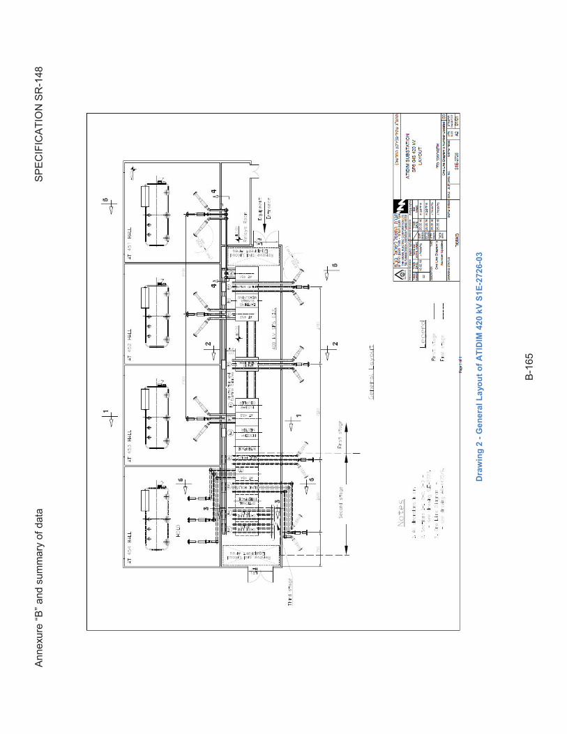
Ann
exur
e “B
” an
d su
mm
ary
of d
ata
SP
EC
IFIC
AT
ION
SR
-148
B-1
65
Dra
win
g 2
- G
en
era
l L
ayo
ut
of
AT
IDIM
42
0 k
V S
1E
-272
6-0
3
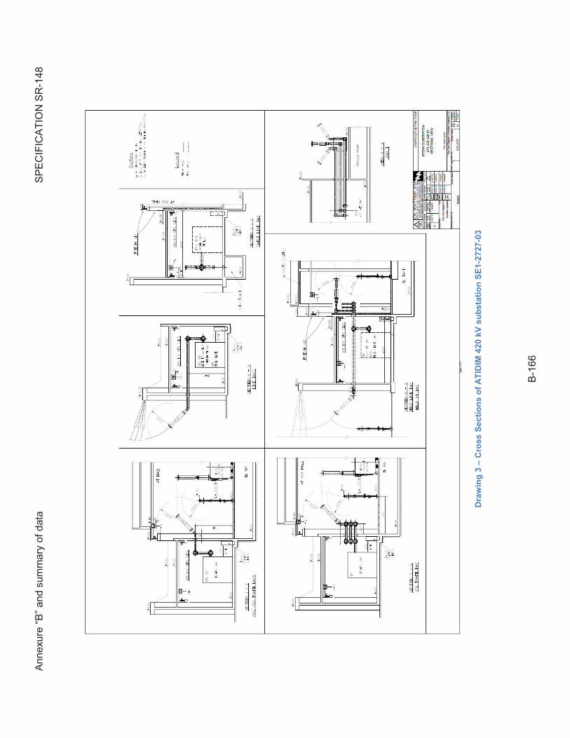
Ann
exur
e “B
” an
d su
mm
ary
of d
ata
SP
EC
IFIC
AT
ION
SR
-148
B-1
66
Dra
win
g 3
– C
ross
Se
cti
on
s o
f A
TID
IM 4
20
kV
su
bs
tati
on
SE
1-2
727
-03
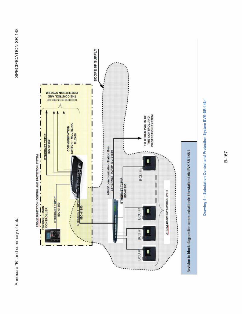
Ann
exur
e “B
” an
d su
mm
ary
of d
ata
SP
EC
IFIC
AT
ION
SR
-148
B-1
67
Dra
win
g 4
– S
ub
sta
tio
n C
on
tro
l a
nd
Pro
tec
tio
n S
ys
tem
EV
K-S
R-1
48
-1
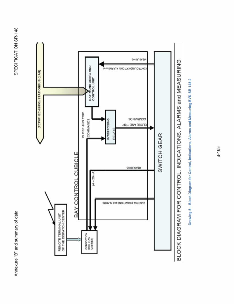
Ann
exur
e “B
” an
d su
mm
ary
of d
ata
SP
EC
IFIC
AT
ION
SR
-148
B-1
68
Dra
win
g 5
– B
loc
k D
iag
ram
fo
r C
on
tro
l, I
nd
ica
tio
ns
, A
larm
s a
nd
Mea
su
rin
g E
VK
-SR
-14
8-2
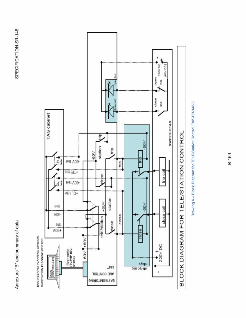
Ann
exur
e “B
” an
d su
mm
ary
of d
ata
SP
EC
IFIC
AT
ION
SR
-148
B-1
69
Dra
win
g 6
– B
loc
k D
iag
ram
fo
r T
EL
E/S
tati
on
Co
ntr
ol
EV
K-S
R-1
48
-3
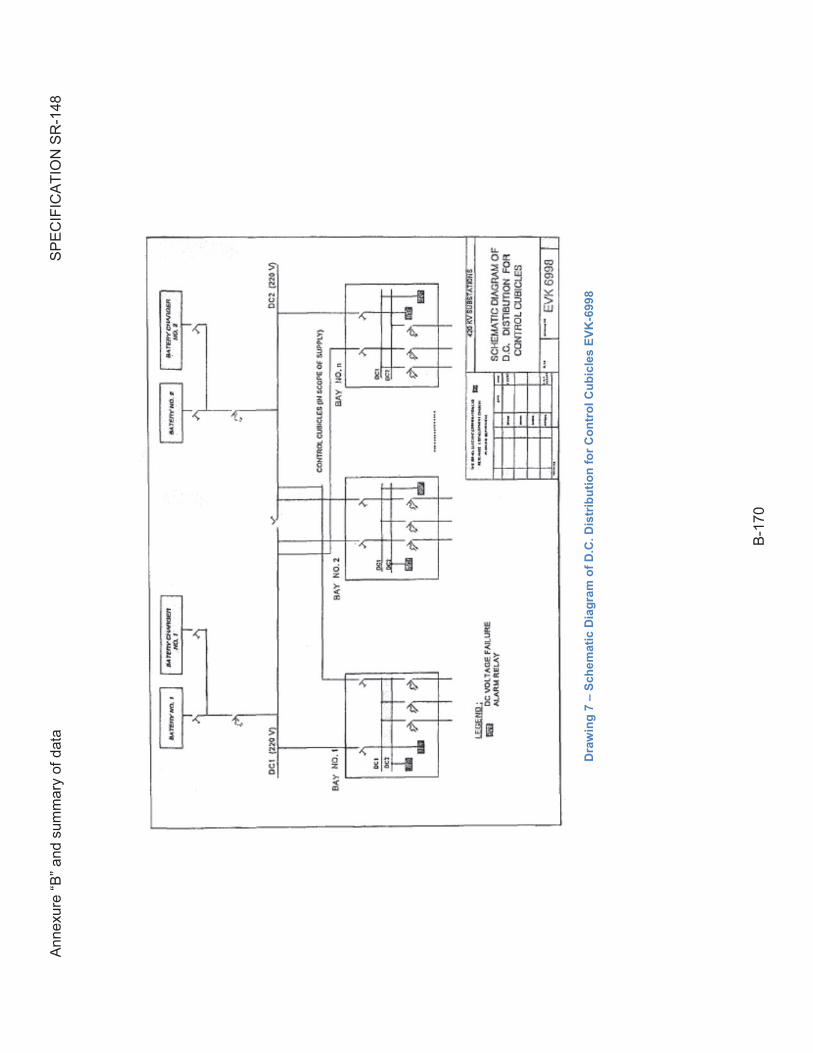
Ann
exur
e “B
” an
d su
mm
ary
of d
ata
SP
EC
IFIC
AT
ION
SR
-148
B-1
70
Dra
win
g 7
– S
ch
em
ati
c D
iag
ram
of
D.C
. D
istr
ibu
tio
n f
or
Co
ntr
ol
Cu
bic
les
EV
K-6
99
8
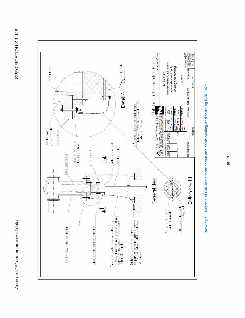
Ann
exur
e “B
” an
d su
mm
ary
of d
ata
SP
EC
IFIC
AT
ION
SR
-148
B-1
71
Dra
win
g 8
– S
ch
em
e o
f G
IS c
ab
le t
erm
ina
tio
n a
nd
ca
ble
se
ali
ng
an
d e
art
hin
g E
VK
-847
1