spring assist roll up instruction manual
DESCRIPTION
Spring Assist Roll Up Instruction manualTRANSCRIPT

Spring-Assist Mesh Curtain
Installation Instructions
System Overview:
Your Aleco Spring-Assist Mesh Curtain Door is a high quality, high performance flexible door system based on proven components and our many years of experience in the vinyl partition fabrication business. We are confident that it will bring you and/or your customers years of reliable and trouble-free service. Your specific system(s) is an “insect blocking” spring-assist roll-up curtain door with “under-header” mount bracketry. Your unit is supplied with Aleco’s Custom Vertical Extrusions that have been sized 9” less than the stated door opening height. Your Insect Blocking Curtain Door is 3” narrower than the stated door opening width. The gap between the curtain door and your door opening is covered and sealed with the Aleco’s Custom Vertical Extrusions and EPDM seal strips.
Unpacking and Inspection:
Please unpack your systems carefully and notify the factory immediately if there are any shortages or if any items have been damaged during transit. Your kit(s) should have all of the necessary hardware and components for a complete installation with the following exceptions (installer-provided hardware):
1. Extrusion, Bracketry, and Valence Panel mounting fasteners that are unique to your specific building material and jamb composition.
FOR ANY QUESTIONS OR COMMENTS, PLEASE CONTACT AN ALECO REPRESENTATIVE 2720 E. Avalon Ave. Muscle Shoals, AL 35661 • Phone (256) 248-2402 or toll free 1-800-633-3120
Fax: 1-800-750-9616 • email: [email protected] • www.aleco.com 1

System Assembly:
Custom Extrusion Mounting:
The Custom Extrusion should be mounted “flush” to the inner building surface as shown in the following diagram (Diagram 1). There should be small “TL” (Top Left) and “TR” (Top Right) markings on the vertical extrusions which may help you with the orientations. The bottoms of the extrusions should be at the floor elevation (resting on the floor). It is recommended that the extrusions be secured to the door opening with fasteners within approximately 5” of each end of the extrusions, and additional fasteners on at least 3’ centers. Specific fastener selection and mounting methodology is left up to the installer and “best practices for the door opening material. Be very careful when drilling the Vertical Extrusions as to not damage the EPDM seal strips.
Diagram #1 (Extrusion and Opening Layout)
FOR ANY QUESTIONS OR COMMENTS, PLEASE CONTACT AN ALECO REPRESENTATIVE 2720 E. Avalon Ave. Muscle Shoals, AL 35661 • Phone (256) 248-2402 or toll free 1-800-633-3120
Fax: 1-800-750-9616 • email: [email protected] • www.aleco.com 2

Spring and Idler Bracket Installation:
The Spring and Idler Bracket Assemblies should be mounted using the same “best practices” and fasteners as applied with the installation of the custom extrusions. As shown in the following diagram (Diagram 2) the “Idler End” bracket and hardware should be mounted on the RIGHT side of the door opening when viewed from the exterior of the building. The “Spring End” bracket and hardware should be mounted on the LEFT.
Custom Extrusion
Diagram #2 (Bracketry and Opening Layout)
The extrusions and brackets have been sized to provide approximately ½” of clearance between the tops of the Idler and Motor brackets and the underside of the door opening header. This clearance will be beneficial when it comes time to install the “double-baffle” support bar.
Particular care must be taken with the positioning of the brackets with respect to the extrusions. As shown in Photo 1 (EPDM removed for clarity), the “funnel lead-in” of the bracket should be positioned directly above the custom extrusion, and should be positioned in such a manner to provide a smooth transition into the extrusion track. Shim or otherwise adjust the position of the bracket to ensure that any misalignment does not exceed 10”.
FOR ANY QUESTIONS OR COMMENTS, PLEASE CONTACT AN ALECO REPRESENTATIVE 2720 E. Avalon Ave. Muscle Shoals, AL 35661 • Phone (256) 248-2402 or toll free 1-800-633-3120
Fax: 1-800-750-9616 • email: [email protected] • www.aleco.com 3

Photo #1 (Bracket to Extrusion Alignment)
As shown in the following photo (Photo 2) the Idler hardware should be installed in the nest of the Idler End Bracket and secured to the door opening with the appropriate fasteners.
Photo #2 (Idler Bracket Mounting)
FOR ANY QUESTIONS OR COMMENTS, PLEASE CONTACT AN ALECO REPRESENTATIVE 2720 E. Avalon Ave. Muscle Shoals, AL 35661 • Phone (256) 248-2402 or toll free 1-800-633-3120
Fax: 1-800-750-9616 • email: [email protected] • www.aleco.com 4
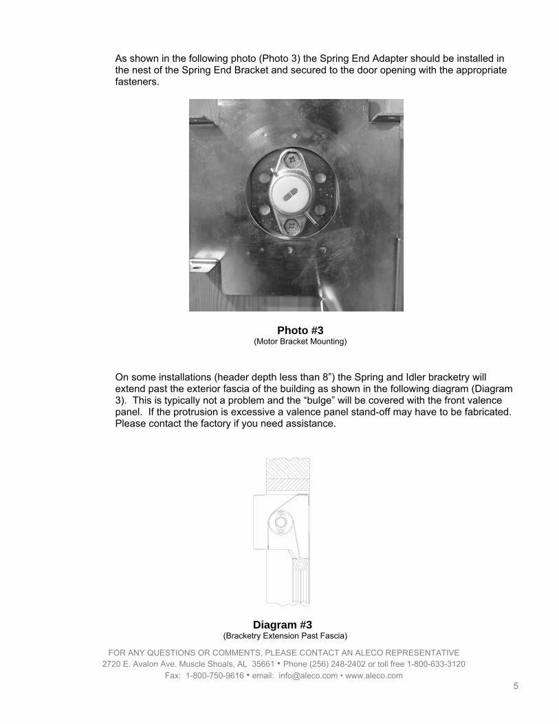
As shown in the following photo (Photo 3) the Spring End Adapter should be installed in the nest of the Spring End Bracket and secured to the door opening with the appropriate fasteners.
Photo #3 (Motor Bracket Mounting)
On some installations (header depth less than 8”) the Spring and Idler bracketry will extend past the exterior fascia of the building as shown in the following diagram (Diagram 3). This is typically not a problem and the “bulge” will be covered with the front valence panel. If the protrusion is excessive a valence panel stand-off may have to be fabricated. Please contact the factory if you need assistance.
Diagram #3
(Bracketry Extension Past Fascia)
FOR ANY QUESTIONS OR COMMENTS, PLEASE CONTACT AN ALECO REPRESENTATIVE 2720 E. Avalon Ave. Muscle Shoals, AL 35661 • Phone (256) 248-2402 or toll free 1-800-633-3120
Fax: 1-800-750-9616 • email: [email protected] • www.aleco.com 5

Spring Roll Preparation:
It will be necessary to prepare the spring-assist roll and establish the initial torsional spring pre-load before installing the unit in the bracketry. Lay the tube on a flat surface and clamp the spring tab with a Vice Grip™ or similar tool as shown in the following photo (Photo 4):
Photo #4 (Setting Spring Pre-Load)
Make sure that there is no initial pre-load on the spring. If there is, carefully unload it by holding back the “catches” and unwinding the tab in a CCW (counter-clockwise) direction until there is no torque on the spring. Establish the preload by turning the tab in a CW (clockwise) direction the number of turns prescribed in the following table (Table 1). Be very careful during this operation. Torsional springs can store a tremendous amount of energy and can cause serious personal injury if not operated in a careful and conscientious manner.
FOR ANY QUESTIONS OR COMMENTS, PLEASE CONTACT AN ALECO REPRESENTATIVE 2720 E. Avalon Ave. Muscle Shoals, AL 35661 • Phone (256) 248-2402 or toll free 1-800-633-3120
Fax: 1-800-750-9616 • email: [email protected] • www.aleco.com 6

Door Size
Number of Turns
8’ x 8’ 9
8’ x 9’ 10
8’ x 10’ 11
9’ x 9’ 11
9’ x 10’ 13
10’ x 8’ 13
10’ x 10’ 14
10’ x 12’ 16
10’ x 14’ 17
12’ x 10’ 17
12’ x 12’ 19
12’ x 14’ 20
14’ x 14’ 24
Table #1
(Spring Pre-Load)
After the pre-load has been established ensure that one or both of the “catches” are locked into the notches of the spring tab mechanism before removing the Vice Grip™.
FOR ANY QUESTIONS OR COMMENTS, PLEASE CONTACT AN ALECO REPRESENTATIVE 2720 E. Avalon Ave. Muscle Shoals, AL 35661 • Phone (256) 248-2402 or toll free 1-800-633-3120
Fax: 1-800-750-9616 • email: [email protected] • www.aleco.com 7

Spring-Assist Roll Installation:
Prior to the installation of the roll into the bracketry it should be fully inspected for completeness and proper assembly. Make sure that the spring-loaded idler is installed and fully seated in the tube. While the photographs will depict an installation with the track rollers loaded into the fiberglass pulltrusion bushings, it is often easier to perform this step without the rollers. There will be a section later in these instructions on the installation of the rollers after the tube has been installed. The installation of the roller tube can best be accomplished by two workers on ladders or one worker on a scaffold or scissors jack (with at least a 6’ platform). At all times be aware of the angle of the roller tube and make sure that no parts such as the rollers “slide out” during the installation process. Orient the roller tube so that the spring tab is on the “left side” of the door opening as you face the opening from the exterior side. Raise the complete tube assembly until both ends are within about a foot of their respective mounting brackets. Carefully tilt the idler end of the roller tube up and engage the 12mm extension of the spring loaded idler cap into the corresponding bore of the ball-eye idler mount as shown in the following photo (Photo 5):
Photo #5 (Idler Shaft Engagement)
FOR ANY QUESTIONS OR COMMENTS, PLEASE CONTACT AN ALECO REPRESENTATIVE 2720 E. Avalon Ave. Muscle Shoals, AL 35661 • Phone (256) 248-2402 or toll free 1-800-633-3120
Fax: 1-800-750-9616 • email: [email protected] • www.aleco.com 8
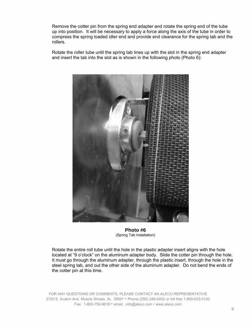
Remove the cotter pin from the spring end adapter and rotate the spring end of the tube up into position. It will be necessary to apply a force along the axis of the tube in order to compress the spring loaded idler end and provide end clearance for the spring tab and the rollers. Rotate the roller tube until the spring tab lines up with the slot in the spring end adapter and insert the tab into the slot as is shown in the following photo (Photo 6):
Photo #6 (Spring Tab Installation)
Rotate the entire roll tube until the hole in the plastic adapter insert aligns with the hole located at “9 o’clock” on the aluminum adapter body. Slide the cotter pin through the hole. It must go through the aluminum adapter, through the plastic insert, through the hole in the steel spring tab, and out the other side of the aluminum adapter. Do not bend the ends of the cotter pin at this time.
FOR ANY QUESTIONS OR COMMENTS, PLEASE CONTACT AN ALECO REPRESENTATIVE 2720 E. Avalon Ave. Muscle Shoals, AL 35661 • Phone (256) 248-2402 or toll free 1-800-633-3120
Fax: 1-800-750-9616 • email: [email protected] • www.aleco.com 9

If the rollers are installed you can manually unwrap one to two turns of material from the roll and check the engagement and transition of the roller from the side brackets into the custom extrusion. If the rollers are not installed, unwrap enough of the curtain door to allow it to extend into the vertical extrusions. Refer to the addendum at the end of this document an install just the bottom two rollers (at each end of the bottom fiberglass pulltrusion). Adjust and/or shim the brackets or vertical extrusions as required to ensure a smooth and repeatable roller transition into the extrusion.
Photo #7 (Roller into Extrusion Transition)
At this point the curtain door should be slightly “unrolled” and the bottom set of rollers should be engaged with the vertical extrusions. Completely unwrap both “pull straps” and secure the ends to “strap saddles” using the buckles as shown in the following photo (Photo 8). Both straps should be adjusted to have a slight and equal amount of tension in them.
Photo #8 (Pull Strap and Buckle)
FOR ANY QUESTIONS OR COMMENTS, PLEASE CONTACT AN ALECO REPRESENTATIVE 2720 E. Avalon Ave. Muscle Shoals, AL 35661 • Phone (256) 248-2402 or toll free 1-800-633-3120
Fax: 1-800-750-9616 • email: [email protected] • www.aleco.com 10

FOR ANY QUESTIONS OR COMMENTS, PLEASE CONTACT AN ALECO REPRESENTATIVE 2720 E. Avalon Ave. Muscle Shoals, AL 35661 • Phone (256) 248-2402 or toll free 1-800-633-3120
Fax: 1-800-750-9616 • email: [email protected] • www.aleco.com 11
It is very important to note that the pull straps not only provide for a mechanism to close the curtain door, they also provide the “up limit position” for the unit. If these straps are not properly secured or adjusted the curtain door can “over-travel” when being raised. This may damage the curtain or spring mechanism. After the pull straps have been secured and adjusted the rest of the rollers should be installed. Please refer to the addendum at the end of this document. Do no trim the pull straps to their final length at this time.
Final Mechanical Assembly:
Double-Baffle Support Bar:
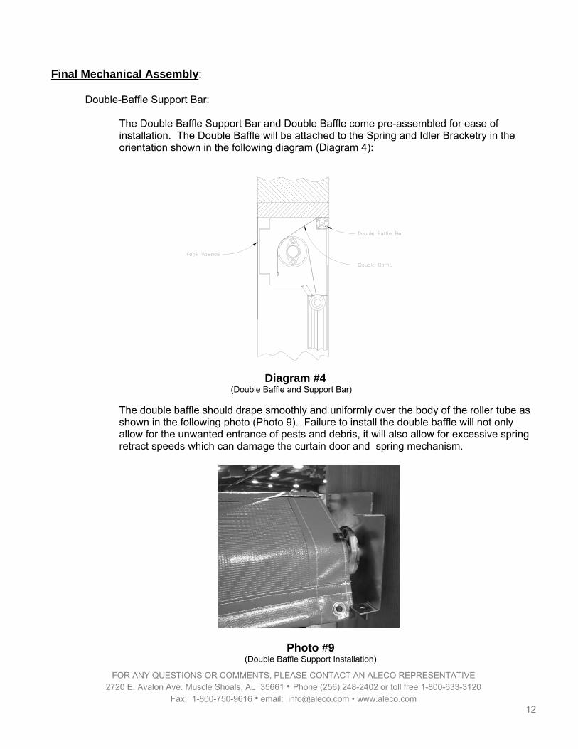
The Double Baffle Support Bar and Double Baffle come pre-assembled for ease of installation. The Double Baffle will be attached to the Spring and Idler Bracketry in the orientation shown in the following diagram (Diagram 4):
Diagram #4
(Double Baffle and Support Bar)
The double baffle should drape smoothly and uniformly over the body of the roller tube as shown in the following photo (Photo 9). Failure to install the double baffle will not only allow for the unwanted entrance of pests and debris, it will also allow for excessive spring retract speeds which can damage the curtain door and spring mechanism.
Photo #9 (Double Baffle Support Installation)
FOR ANY QUESTIONS OR COMMENTS, PLEASE CONTACT AN ALECO REPRESENTATIVE 2720 E. Avalon Ave. Muscle Shoals, AL 35661 • Phone (256) 248-2402 or toll free 1-800-633-3120
Fax: 1-800-750-9616 • email: [email protected] • www.aleco.com 12

There are two standard methods for assembling the Double Baffle Support Bar to the Idler and Spring Bracketry. Both methods work equivalently well, and the only determining factor is the clearance and accessibility provided by your particular installation. Method #1:
Pre-assemble the ¼-20 x 3/8 Button Headed fasteners through the “ears” of the bracketry and into the ¼-20 square nuts as shown in the following photo (Photo 10). Only engage the fastener into the nut by a few threads.
Photo #10 (Double Baffle Support Fastener)
Position the Double Baffle Support Bar over the top of the curtain roller tube and engage the square nut on one of the brackets into corresponding extruded groove of the support bar. Slide the support bar onto the nut and then engage the nut on the opposite bracket at the other end of the support bar into the groove. Slide the support bar until it is approximately centered over the curtain and firmly tighten both fasteners.
Method #2: Pre-load a ¼-20 square nut into the bottom groove at each end of the Double Baffle Support Bar as shown in the following photo (Photo 11). Position the nut approximately 1.5” inches in from the end of the bar.
Photo #11 (Double Baffle Support Nut)
FOR ANY QUESTIONS OR COMMENTS, PLEASE CONTACT AN ALECO REPRESENTATIVE 2720 E. Avalon Ave. Muscle Shoals, AL 35661 • Phone (256) 248-2402 or toll free 1-800-633-3120
Fax: 1-800-750-9616 • email: [email protected] • www.aleco.com 13
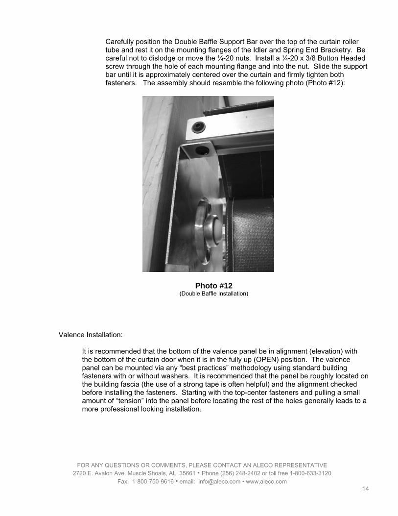
Carefully position the Double Baffle Support Bar over the top of the curtain roller tube and rest it on the mounting flanges of the Idler and Spring End Bracketry. Be careful not to dislodge or move the ¼-20 nuts. Install a ¼-20 x 3/8 Button Headed screw through the hole of each mounting flange and into the nut. Slide the support bar until it is approximately centered over the curtain and firmly tighten both fasteners. The assembly should resemble the following photo (Photo #12):
Photo #12 (Double Baffle Installation)
Valence Installation:
It is recommended that the bottom of the valence panel be in alignment (elevation) with the bottom of the curtain door when it is in the fully up (OPEN) position. The valence panel can be mounted via any “best practices” methodology using standard building fasteners with or without washers. It is recommended that the panel be roughly located on the building fascia (the use of a strong tape is often helpful) and the alignment checked before installing the fasteners. Starting with the top-center fasteners and pulling a small amount of “tension” into the panel before locating the rest of the holes generally leads to a more professional looking installation.
FOR ANY QUESTIONS OR COMMENTS, PLEASE CONTACT AN ALECO REPRESENTATIVE 2720 E. Avalon Ave. Muscle Shoals, AL 35661 • Phone (256) 248-2402 or toll free 1-800-633-3120
Fax: 1-800-750-9616 • email: [email protected] • www.aleco.com 14

FOR ANY QUESTIONS OR COMMENTS, PLEASE CONTACT AN ALECO REPRESENTATIVE 2720 E. Avalon Ave. Muscle Shoals, AL 35661 • Phone (256) 248-2402 or toll free 1-800-633-3120
Fax: 1-800-750-9616 • email: [email protected] • www.aleco.com 15
Final Setup and Operation: Operation:
The operation of your Aleco Spring-Assist Insect Blocking Mesh Door is quite simple, although a little training is sometimes required. To lower the door, simply grab one of the pull strap handles (either interior or exterior) and pull the door down in a hand-over-hand manner. Continue to pull the door down until the bottom seal comes in contact with the floor or compresses slightly. Relieve the downward force on the handle and allow the door to slowly move upward. It will “catch and detent” (much like a window shade) at the first available latch position (adjusting the location of these latch positions is discussed in a later section of this document). Warning: The curtain door is attached to the roller tube with Velcro™ for ease of field replacement. There is an additional “safety wrap” of approximately 18” of material around the roller tube when the door is in the fully closed position. If an operator continues to pull down on the door after it has reached the closed position it is possible for the Velcro™ to “unzip” allowing the door to become detached from the roller tube. This will cause the roller tube spring to lose all of its spring pre-load and a complete re-installation will be required. To raise or open the door, grab one of the handles and pull the door down an additional 3-4” (three to four inches). Completely release the handle. The door should completely roll up, being stopped by the tension in the pull straps. It is not necessary to “jerk” or “snap” the door in order to get it to open. It is not generally possible to get the door to open from a middle or intermediate position. It must start from the “completely closed” position in order to open properly.
Spring Pre-Load:
If the door does not reliably open all of the way it is necessary to increase the spring pre-load. This adjustment must be done after the EPDM strips and Double Baffle have been installed. During this adjustment you will be dealing with a pre-loaded spring assembly and will be fighting the effects of gravity on the door. Be sure to have solid footing, a good grasp on the roller tube, and use all due caution. Pull the door down until it is approximately halfway closed. Ensure that it has “latched” into this position and that one or both of the “catches” are locked into the notches of the spring tab mechanism. Grasp the roller tube firmly with one hand and slowly rotate it in a CCW (counter clockwise) direction as indicated in the following diagram (Diagram 5):

Diagram #5 (CCW Rotation)
This action should unload the force on the cotter pin and I will be possible to pull it out of the spring adapter assembly. Carefully continue to rotate the roller tube an additional ½ to 1 turns in the CCW direction until the hole in the aluminum adapter housing aligns with the corresponding hole in the plastic insert. Reinstall the cotter pin as shown in the following photo (Photo 13):
Photo #13 (Cotter Pin Installation)
FOR ANY QUESTIONS OR COMMENTS, PLEASE CONTACT AN ALECO REPRESENTATIVE 2720 E. Avalon Ave. Muscle Shoals, AL 35661 • Phone (256) 248-2402 or toll free 1-800-633-3120
Fax: 1-800-750-9616 • email: [email protected] • www.aleco.com 16

Test the action and operation of the door. If additional spring pre-load is required repeat the above procedure. The final adjustment should be “just enough” pre-load to ensure a reliable and repeatable opening of the door plus ½-1 additional turns of pre-load. If the door opens too aggressively (speed) or if it is too hard to operate it may be necessary to reduce the spring pre-load on the door. During this adjustment you will be dealing with a pre-loaded spring assembly and will be fighting the effects of gravity on the door. Be sure to have solid footing, a good grasp on the roller tube, and use all due caution. Pull the door down until it is approximately halfway closed. Ensure that it has “latched” into this position and that one or both of the “catches” are locked into the notches of the spring tab mechanism. Grasp the roller tube firmly with one hand and slowly rotate it in a CCW (clockwise) direction as indicated in Diagram 5 (above). This action should unload the force on the cotter pin and I will be possible to pull it out of the spring adapter assembly. Carefully rotate the roller tube ½ to 1 turns in the CW direction as indicated in the following diagram (Diagram 6) until the hole in the aluminum adapter housing aligns with the corresponding hole in the plastic insert. Reinstall the cotter pin as shown in Photo 13 (above).
Diagram #6 (CW Rotation)
FOR ANY QUESTIONS OR COMMENTS, PLEASE CONTACT AN ALECO REPRESENTATIVE 2720 E. Avalon Ave. Muscle Shoals, AL 35661 • Phone (256) 248-2402 or toll free 1-800-633-3120
Fax: 1-800-750-9616 • email: [email protected] • www.aleco.com 17

FOR ANY QUESTIONS OR COMMENTS, PLEASE CONTACT AN ALECO REPRESENTATIVE 2720 E. Avalon Ave. Muscle Shoals, AL 35661 • Phone (256) 248-2402 or toll free 1-800-633-3120
Fax: 1-800-750-9616 • email: [email protected] • www.aleco.com 18
“Closed” Position Adjustment:
When the door is fully closed the bottom seal should be in contact with the floor or slightly compressed (1-2”). If there are no detent latch position that correspond to this position it will be necessary to adjust the angular position of the spring tab mount. During this adjustment you will be dealing with a pre-loaded spring assembly and will be fighting the effects of gravity on the door. Be sure to have solid footing, a good grasp on the roller tube, and use all due caution. Pull the door down until it is approximately halfway closed. Ensure that it has “latched” into this position and that one or both of the “catches” are locked into the notches of the spring tab mechanism. Grasp the roller tube firmly with one hand and slowly rotate it in a CCW (clockwise) direction as indicated in Diagram 5 (above). This action should unload the force on the cotter pin and I will be possible to pull it out of the spring adapter assembly. In the stock configuration it is at the “9 o’clock” (horizontal) position. Carefully rotate the roller tube in the CW or CCW directions until the holes in the aluminum adapter housing at the “7 o’clock” or “11 o’clock” positions aligns with the corresponding hole in the plastic insert. Reinstall the cotter pin. Each alternate position will raise or lower the bottom latch position by approximately 2”. Standard latching positions are located approximately every 5”. Note that there is also a hole at the 12 o’clock (vertical) position. This hole should be used with caution since it reduces the aggressiveness and reliability of the latches.
“Open” Position Adjustment:
When the door is fully open the lower set of rollers should be within a few inches of the top of the vertical extrusions. Allowing the rollers to travel up into the “funnel lead-in” of the Spring and Idler brackets may lead to unreliable operation. The open position is established by adjusting the buckles at the pull strap mounting location. Lengthen the straps to raise the door, shorten the straps to lower it. Both straps should be adjusted in an equal manner and the final tension on both straps when the door is in the open position should be roughly equal. After the final open position has been established the pull straps can be trimmed and the ends of the webbing “flame fused”.
Final Check:
Double check the operation and end-stop positions on your door. If everything is satisfactory, flair or bend the ends of the cotter pin to lock it into position. If the cotter pin is not properly secured it may fall out, damaging the door unit and perhaps causing bodily harm.
FOR ANY QUESTIONS OR COMMENTS, PLEASE CONTACT AN ALECO REPRESENTATIVE 2720 E. Avalon Ave. Muscle Shoals, AL 35661 • Phone (256) 248-2402 or toll free 1-800-633-3120
Fax: 1-800-750-9616 • email: [email protected] • www.aleco.com 19
Periodic Maintenance:
Over time the action of the door may become sluggish and the unit may not retract to the “full up” position. This is usually due to the accumulation of surface contaminates on the double baffle and the evaporation of the natural surface lubricant on the vinyl material. Increasing the spring pre-load may compensate for this problem, but the preferred remedy is to re-coat the vinyl door and double baffle with a dry lubricant. Aleco recommends lightly spraying the upper ⅓ of the “inside” door material with a silicone lubricant (available at most hardware stores). Operating the door will transfer some of this lubricant to the surface of the double baffle. Repeating this process every 6 to 12 months will keep your door operating in a smooth and reliable manner.
The assembly, installation, and set-up of your Aleco Spring-Assist Curtain Door is now complete and it is ready for typical operation. It is a virtually maintenance free unit and should give you years of reliable service. We want to thank you again for your business and the opportunity to partner with your firm on this project. Please don’t hesitate to contact us if you have any questions regarding these instructions or encounter any problems with the installation or performance of your door.

Addendum
Installation of Track Rollers after the Spring Tube is Mounted:
The track rollers can easily be installed after the Spring Tube and Curtain Assembly have been mounted. It is essential that the appropriate steps for securing the spring tab have already been performed prior attempting this step. The pull straps should be secured and adjusted for the installation of all rollers with the exception of the bottom two (bottom pulltrusion tube). The rollers can be installed on one side and then the other, or on both sides simultaneously. To install a roller into one of the pulltrusion (stiffener) tubes, pull the curtain down until the pulltrusion pocket is approximately 8” below the junction of the bracket “funnel” and top of the custom extrusion. Allow the spring mechanism to “latch” at that position and pull the edge of the pulltrusion pocket out of the track and clear of the edge of the building. Locate the nylon bushing at the end of the pulltrusion tube and slide the shaft of a roller into it as indicated in the following photo (Photo 14):
Photo #14 (Roller Installation)
FOR ANY QUESTIONS OR COMMENTS, PLEASE CONTACT AN ALECO REPRESENTATIVE 2720 E. Avalon Ave. Muscle Shoals, AL 35661 • Phone (256) 248-2402 or toll free 1-800-633-3120
Fax: 1-800-750-9616 • email: [email protected] • www.aleco.com 20

Raise the roller up, slide it across the face of the Spring or Idler bracket, and drop it into the “funnel” of the bracketry as shown in the following photo (Photo 15):
Photo #15 (Roller Into Funnel)
Repeat this procedure for the remaining pulltrusion tubes. Ensure that the rollers enter the custom extrusion properly and that the edges of the curtain “pop” into the extrusion and/or EPDM seals.
FOR ANY QUESTIONS OR COMMENTS, PLEASE CONTACT AN ALECO REPRESENTATIVE 2720 E. Avalon Ave. Muscle Shoals, AL 35661 • Phone (256) 248-2402 or toll free 1-800-633-3120
Fax: 1-800-750-9616 • email: [email protected] • www.aleco.com 21