spring 2000john kristoff1 network layer computer networks john ourada
Post on 20-Dec-2015
218 views
TRANSCRIPT

Spring 2000 John Kristoff 1
Network Layer
Computer NetworksJohn Ourada

Spring 2000 John Kristoff 2
Where are we?
Spring 2000 John Kristoff 3
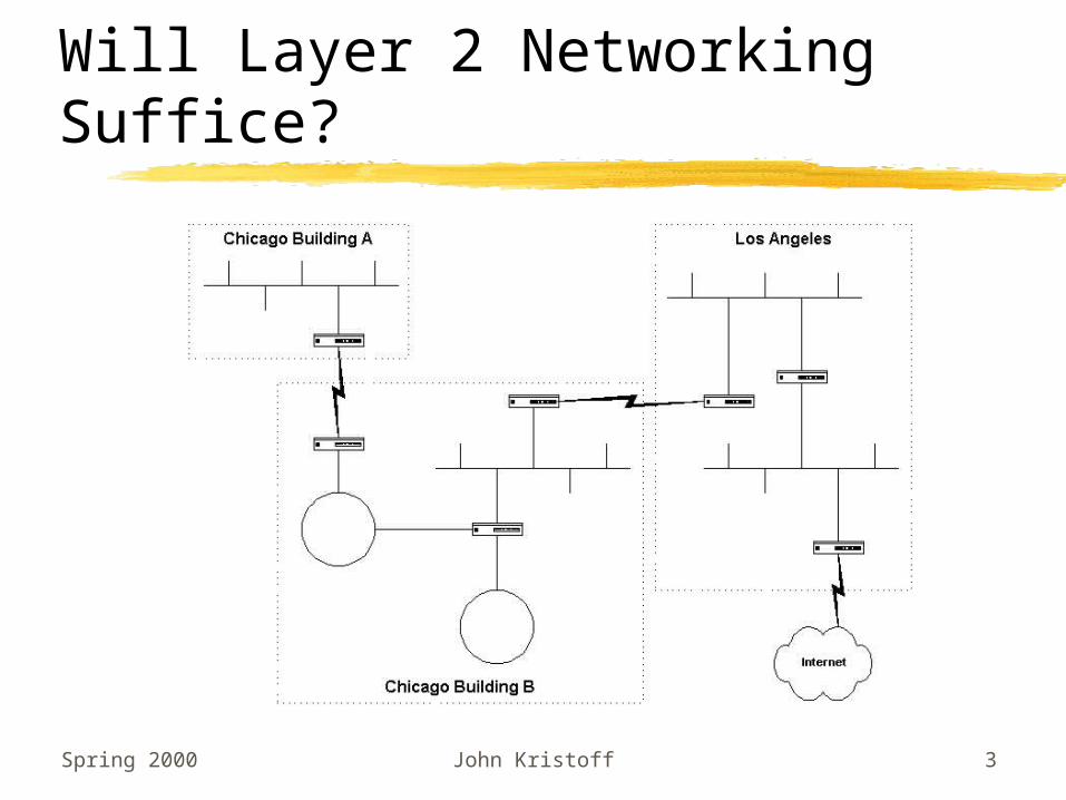
Will Layer 2 Networking Suffice?

Spring 2000 John Kristoff 4
Motivation
Connect various link technologies to form a larger internetwork
Universal addressing scheme required General purpose use Hides underlying technologies from end user Facilitate communicate between autonomous
domains Able to move packets between any host on the
internetwork

Spring 2000 John Kristoff 5
Connecting Heterogeneous Networks
Computer System used Special purpose Dedicated Works with LAN or WAN technologies Known as
routergateway

Spring 2000 John Kristoff 6
Illustration of a Router
Cloud denotes an arbitrary networkOne interface per network

Spring 2000 John Kristoff 7
Important Idea
A router can interconnect networks that use different technologies,
including different media and media access techniques, physical
addressing schemes or frame formats.

Spring 2000 John Kristoff 8
The Internet Concept

Spring 2000 John Kristoff 9
Key Functions of the Network Layer
Global AddressingFragmentationRouting
We’ll be primarily concerned with addressing and routing

Spring 2000 John Kristoff 10
Example Network Layer: Internet Protocol (IP)
Standardized by IETF as RFC 791Most popular Layer 3 protocolCore protocol used on the public InternetConnectionless protocol
datagrams contain identity of the destination each datagram sent/handled independently
Of utmost importance for this class!

Spring 2000 John Kristoff 11
IP Addressing
Provides an abstractionIndependent of hardware (MAC)
addressingUsed by
higher layer protocols applications

Spring 2000 John Kristoff 12
IP Address
Virtual only understood by software
Used for all communication across an internetwork
32-bit integerUnique value for each host/interface

Spring 2000 John Kristoff 13
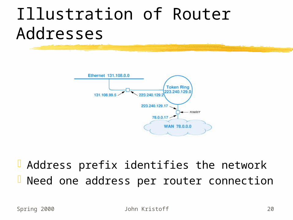
IP Address Assignment
An IP address does not identify a specific computer. Instead, each IP
address identifies a connection between a computer and a network.
A computer with multiple network connections (e.g., a router) must be
assigned one IP address for each connection.

Spring 2000 John Kristoff 14
IP Address Details
Divided into two parts prefix identifies the network suffix identifies the host/interface
Global authority assigns unique prefix for the network
Local administrator assigns unique suffix for the host/interface

Spring 2000 John Kristoff 15
Class of IP Addresses (Historical)
Initial bits determined the class The class determines the boundary between prefix and suffix

Spring 2000 John Kristoff 16
Dotted Decimal Notation
Shorthand for IP addressesAllows humans to avoid binaryRepresents each octet in decimal
separated by dotsNOT the same as names like
www.depaul.edu

Spring 2000 John Kristoff 17
Examples of Dotted Decimal Notation
Four decimal values per 32-bit address Each decimal number
represents eight bits is between 0 and 255 inclusive

Spring 2000 John Kristoff 18
Classes and Network Size (Historical)
Maximum size determined by class of address Class A large Class B medium Class C small

Spring 2000 John Kristoff 19
Addressing Example
Spring 2000 John Kristoff 20
Illustration of Router Addresses
Address prefix identifies the networkNeed one address per router connection

Spring 2000 John Kristoff 21
Special Addresses
Network Address not used in packets Loopback addresses never leave the local computer
Spring 2000 John Kristoff 22
IP Addressing: Problems with Classes
Internet growthRouting table sizeExhaustion of addressesAdministration overheadMisappropriation of addresses
Spring 2000 John Kristoff 23
IP Addressing: Solutions
SubnettingVariable Length Subnet Mask (VLSM)SupernettingClassless InterDomain Routing
(CIDR)

Spring 2000 John Kristoff 24
Subnetting
Split the suffix into a local network portion and a smaller host id portion
Subnet mask becomes 255.255.255.0 for an 8-bit subnet mask

Spring 2000 John Kristoff 25
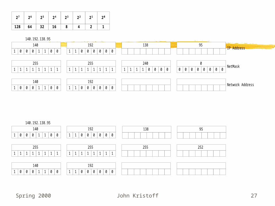
Subnetting
Subnet boundaries fall between any of the 32 bits in an IP address Can be complex and confusing, know binary if not not on 8-bit
boundaries

Spring 2000 John Kristoff 26
128 64 32 16 8 4 2 1
1
2021222324252627
0 0 0 1 1 0 0
140
1 1 0 0 0 0 0 0
192
0 0 1 1 1 0 0 0
56
0 0 1 0 1 1 0 1
45
1 1 1 1 1 1 1 1
255
1 1 1 1 1 1 1 1
255
1 1 1 1 1 1 1 1
255
0 0 0 0 0 0 0 0
0
IP Address
NetMask
1 0 0 0 1 1 0 0
140
1 1 0 0 0 0 0 0
192
0 0 1 1 1 0 0 0
56
0 0 0 0 0 0 0 0
0
Network Address
140.192.56.0/2424-bit mask8-bit subnet mask
140.192.56.45
1 0 0 0 1 1 0 0
140
1 1 0 0 0 0 0 0
192
0 0 1 1 1 0 0 0
56
0 0 1 0 1 1 0 1
45
1 1 1 1 1 1 1 1
255
1 1 1 1 1 1 1 1
255
1 1 1 1 0 0 0 0
240
0 0 0 0 0 0 0 0
0
1 0 0 0 1 1 0 0
140
1 1 0 0 0 0 0 0
192
0 0 1 1 0 0 0 0
48
0 0 0 0 0 0 0 0
0
140.192.48.0/2020-bit mask4-bit subnet mask
140.192.56.45
IP Address
NetMask
Network Address
Network Subnet Host
Network Subnet Host
Spring 2000 John Kristoff 27
128 64 32 16 8 4 2 1
1
2021222324252627
0 0 0 1 1 0 0
140
1 1 0 0 0 0 0 0
192 138 95
1 1 1 1 1 1 1 1
255
1 1 1 1 1 1 1 1
255
1 1 1 1 0 0 0 0
240
0 0 0 0 0 0 0 0
0
IP Address
NetMask
1 0 0 0 1 1 0 0
140
1 1 0 0 0 0 0 0
192Network Address
140.192.138.95
1 0 0 0 1 1 0 0
140
1 1 0 0 0 0 0 0
192
1 1 1 1 1 1 1 1
255
1 1 1 1 1 1 1 1
255 255 252
1 0 0 0 1 1 0 0
140
1 1 0 0 0 0 0 0
192
140.192.138.95
138 95

Spring 2000 John Kristoff 28
2 2
Subnet Mask Bits
2 3
2 4
2 5
2 6
2 7
2 8
2 9
2 10
2 11
2 12
2 13
2 14
4 -2 = 2
8 -2 = 6
16 -2 = 14
32 -2 = 30
64 -2 = 62
128 -2 = 126
256 -2 = 254
512 -2 = 510
1024 -2 = 1022
2048 -2 = 2046
4096 -2 = 4094
8192 -2 = 8190
16384 -2 = 16382
2
Bits Combo's N/A Net's
3
4
5
6
7
8
9
10
11
12
13
14
Bits Networks Hosts
4 14 Hosts409414
7 14 Hosts510126
12 14 Hosts624094
6 14 Hosts
10 14 Hosts
Class BSubnet Masks
Bits Networks Hosts
4 14 Hosts1414
2 14 Hosts622
3 14 Hosts
6 14 Hosts
Class CSubnet Masks
2
6
14
30
62
126
254
510
1022
2046
4094
8190
16382
Hosts
ClassB
Hosts
ClassC
2
6
14
30
62

Spring 2000 John Kristoff 29
VLSM
Variable Length Subnet Mask Can be complex and confusing, know binary! Use addresses more efficiently.

Spring 2000 John Kristoff 30
001 00000 = 32001 00001 = 33001 00010 = 34001 00011 = 35001 00100 = 36001 00101 = 37001 00110 = 38001 00111 = 39001 01000 = 40001 01001 = 41001 01010 = 42001 01011 = 43001 01100 = 44001 01101 = 45001 01110 = 46001 01111 = 47001 10000 = 48001 10001 = 49001 10010 = 50001 10011 = 51001 10100 = 52001 10101 = 53001 10110 = 54001 10111 = 55001 11000 = 56001 11001 = 57001 11010 = 58001 11011 = 59001 11100 = 60001 11101 = 61001 1111 0 = 62001 11111 = 63
10011 1001000010
00100
10001
01111
01110
01101
01100
01011 00101
00011
00001
0011001000
01001
01010
10000
00111
10011 1001000010
00100
10001
01111
01110
01101
01100
01011 00101
00011
00001
0011001000
01001
01010
10000
00111
10011 1001000010
00100
10001
01111
01110
01101
01100
01011 00101
00011
00001
0011001000
01001
01010
10000
00111
10011 1001000010
00100
10001
01111
01110
01101
01100
01011 00101
00011
00001
0011001000
01001
01010
10000
00111
001 - 00001 --- 001 - 11110Network 140.192.32.0/19Networks 140.192.33.0/24 --140.192.63.0/24
010 - 00001 --- 010 - 11110Network 140.192.64.0/19Networks 140.192.65.0/24 --140.192.95.0/24
011 - 00001 --- 011 - 11110Network 140.192.96.0/19Networks 140.192.97.0/24 --140.192.127.0/24
100 - 00001 --- 100 - 11110Network 140.192.128.0/19Networks 140.192.129.0/24 --140.192.159.0/24
1 0 0 0 1 1 0 0
140
1 1 0 0 0 0 0 0
192 Host
Big Circles Little Circles

Spring 2000 John Kristoff 31
E 1/1
E 1/1
E 1/0S 2/0
E 1/1
E 1/1
E 1/0
S 2/0 E 1/1
E 1/1
E 1/0
S 2/0
E 1/1
E 1/1
E 1/0S 2/0
S 1/0
S 1/1 S 1/3
S 1/2
R2 R4
R5R3
R1
140.192.33.1
140.192.34.1
140.192.35.1
140.192.49.1
140.192.50.1
140.192.51.1
140.192.17.10
140.192.17.6
140.192.17.5
140.192.17.9
140.192.17.13
140.192.17.17
140.192.17.14
140.192.17.18
140.192.65.1
140.192.66.1
140.192.67.1
140.192.81.1
140.192.82.1
140.192.83.1
140.192.32.0/20
140.192.16.0/20
140.192.64.0/20
140.192.80.0/20140.192.48.0/20
Option 2Variable length mask using 20-bits, 24-bits, and 30-bits

Spring 2000 John Kristoff 32
Supernetting
Combine multiple smaller address classes into a larger block
1 1 0 1 0 0 0 0
208
1 1 0 0 1 1 1 1
207
0 0 1 1 0 1 0 0
52
0 0 0 0 0 0 0 0
0
1 1 0 1 0 0 0 0
208
1 1 0 0 1 1 1 1
207
0 0 1 1 0 1 0 1
53
0 0 0 0 0 0 0 0
0
1 1 0 1 0 0 0 0
208
1 1 0 0 1 1 1 1
207
0 0 1 1 0 1 1 0
54
0 0 0 0 0 0 0 0
0
208.207.52.0/24
208.207.53.0/24
208.207.54.0/24
1 1 0 1 0 0 0 0
208
1 1 0 0 1 1 1 1
207
0 0 1 1 0 1 1 1
55
0 0 0 0 0 0 0 0
0 208.207.55.0/24
1 1 0 1 0 0 0 0
208
1 1 0 0 1 1 1 1
207
0 0 1 1 0 1 0 0
52
0 0 0 0 0 0 0 0
0 208.207.52.0/22

Spring 2000 John Kristoff 33
CIDR
Classless Inter-domain RoutingEmploy supernetting information in
IP routersAdvertise smaller CIDR blocksDecreases the routing table size

Spring 2000 John Kristoff 34
IP Packet (datagram) Format

Spring 2000 John Kristoff 35
IP Datagrams
Can be delayedDuplicatedDelivered out of orderLostCan change routes from packet to
packetAre connectionless

Spring 2000 John Kristoff 36
IP Routing
Performed by routersTable-drivenForwarding on a hop-by-hop basisDestination address used for route
determination

Spring 2000 John Kristoff 37
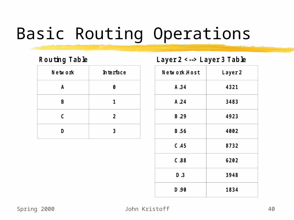
Routing/Forwarding Overview
Strip off layer 2 headers/trailersExtract destination address field, DLook up D in the routing tableFind next hop address, NSend datagram to NAdd on layer 2 headers/trailers

Spring 2000 John Kristoff 38
Routing Basic Operation
A.344321
A.243483
B.294923
B.564002
D.33984
D.901834
C.458732
C.886202
RouterD.1
A.1 B.1
C.1
Basic Routing

Spring 2000 John Kristoff 39
Routing Basic Operation
DA ProtocolP. DA
Netw orkSA
P. DAHost
P. SANetw ork
P. SAHost
Data FCS
P. DANetw ork
P. DAHost
P. SANetw ork
P. SAHost
Data
Layer 2
Layer 3
1234 JIP A3256 34 C 45 Data FCS
A 34 C 45 Data
Layer 2
Layer 3
Spring 2000 John Kristoff 40
Basic Routing Operations
Netw ork
A
B
Interface
0
1
C 2
D 3
Routing Table
Netw ork.Host
A.34
A.24
Layer 2
4321
3483
B.29 4923
B.56 4002
Layer 2 <--> Layer 3 Table
C.45 8732
C.88 6202
D.3 3948
D.90 1834
Spring 2000 John Kristoff 41
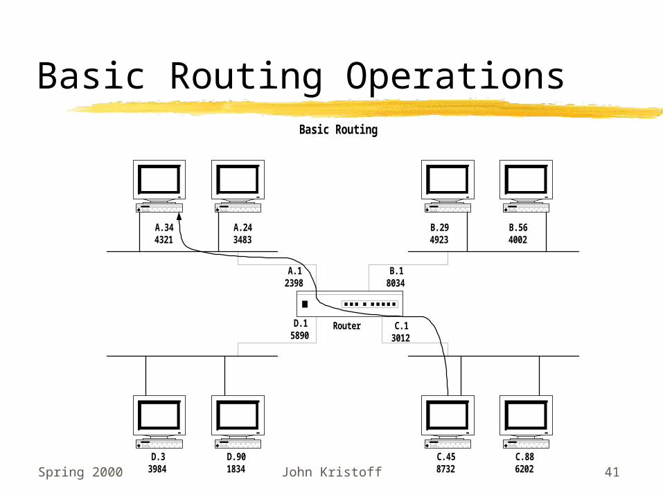
Basic Routing Operations
A.344321
A.243483
B.294923
B.564002
D.33984
D.901834
C.458732
C.886202
RouterD.15890
A.12398
B.18034
C.13012
Basic Routing

Spring 2000 John Kristoff 42
3012 JIP A8732 34 C 45 Data FCS
A 34 C 45 Data
4321 JIP A2398 34 C 45 Data FCS
From C.45 to A.34C.45 know s that A.34 isn't on the same net and sends it to router at C.1Note DA for layer 2
Inside the router the Layer 2 headers and trailers are removed leaving only thelayer 3 packet.The router looks up the packet's DA in the routing table and forw ards to theappropriate interface.
At the interface, layer 2 headers and trailers are added back.DA is the address of the destination host.SA is the address of the router.FCS is recalculated.

Spring 2000 John Kristoff 43
TCP/IP Routing
140.192.10.50060CA23BE45
140.192.10.250060CA34CD29
140.192.100.340060CA4AD2EE
140.192.100.80060CAAABBCC
140.192.201.220060CA3499CC
140.192.201.1260060CA3499DE
140.192.34.340060CA114499
140.192.34.350060CA7819AA
Router140.192.201.1
00C0C1AA3410
140.192.10.100C0C1AA3411
140.192.100.100C0C1AA3412
140.192.34.100C0C1AA3413
IP Routing
Spring 2000 John Kristoff 44
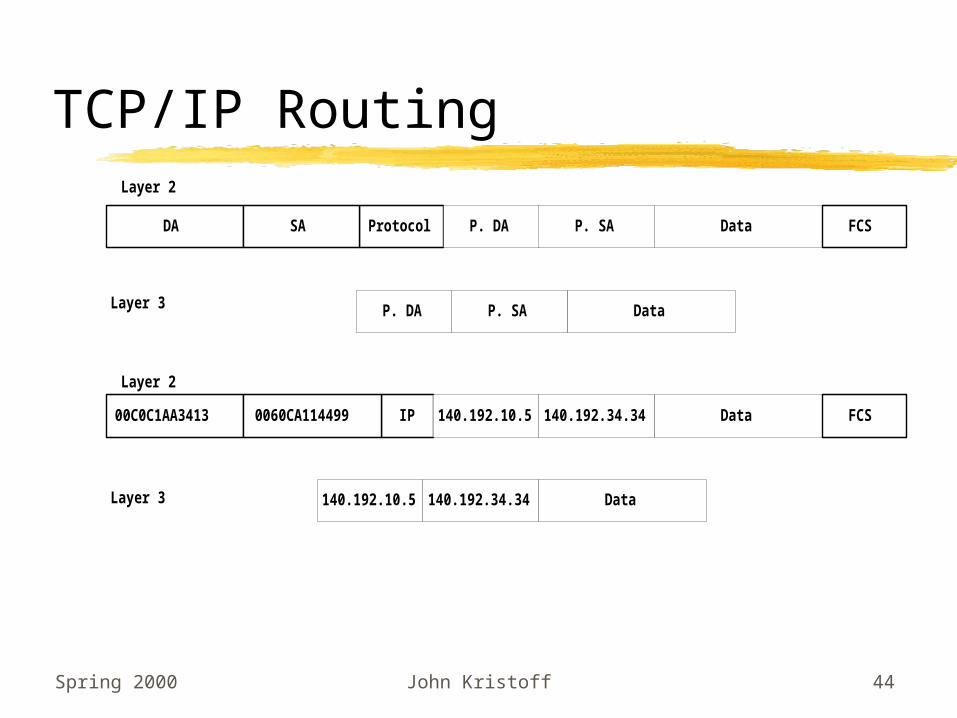
TCP/IP Routing
DA Protocol P. DASA P. SA Data FCS
Data
Layer 2
Layer 3
00C0C1AA3413 IP 140.192.10.50060CA114499 Data FCS
Layer 2
Layer 3
140.192.34.34
140.192.10.5 Data140.192.34.34
P. DA P. SA

Spring 2000 John Kristoff 45
TCP/IP RoutingFrom 140.192.34.34 to 140.192.10.5140.192.34.34 know s that 140.192.10.5 isn't on the same net and sends it to router at 140.192.34.1Note DA for layer 2
Inside the router the Layer 2 headers and trailers are removed leaving only thelayer 3 packet.The router looks up the packet's DA in the routing table and forw ards to theappropriate interface.
At the interface, layer 2 headers and trailers are added back.DA is the address of the destination host.SA is the address of the router.FCS is recalculated.
00C0C1AA3413 IP 140.192.10.50060CA114499 Data FCS140.192.34.34
140.192.10.5 Data140.192.34.34
0060CA23BE45 IP 140.192.10.500C0C1AA3411 Data FCS140.192.34.34

Spring 2000 John Kristoff 46
TCP/IP Routing
Netw ork
140.192.10.0
140.192.100.0
Interface
0
1
140.192.201.0 2
140.192.34.0 3
Routing Table
Netw ork.Host
140.192.10.5
140.192.10.25
Layer 2
0060CA23BE45
0060CA34CD29
140.192.100.34 0060CA4AD2EE
140.192.100.8 0060CAAABBCC
Layer 2 <--> Layer 3 TableARP Table
140.192.201.22 0060CA3499CC
140.192.201.126 0060CA3499DE
140.192.34.34 0060CA114499
140.192.34.35 0060CA7819AA

Spring 2000 John Kristoff 47
ARP Protocol
ARP: Address Resolution Protocol Resolves IP address to MAC address Node sends broadcast looking for another
node140.192.23.1 broadcasts looking for 140.192.23.23
Node replies with MAC address140.192.23.23 replies with 00600A34AA3C
ARP Table: contains records of learned relationships.
Spring 2000 John Kristoff 48
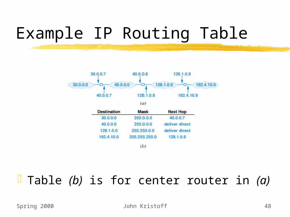
Example IP Routing Table
Table (b) is for center router in (a)

Spring 2000 John Kristoff 49
Routing Table Size
Since each destination in a routing table corresponds to a network, the number of entries in a routing table
is proportional to the number of networks in the internetwork.

Spring 2000 John Kristoff 50
Key Concept
The destination address in a datagram header always refers to the ultimate destination. When a router forwards the datagram to another router, the
address of the next hop does not appear in the datagram header.

Spring 2000 John Kristoff 51
Routing Protocol Requirements
Efficient routing table sizeEfficient routing control messagesRobustness and reliability
prevent loops avoid black holes reconvergence time is short

Spring 2000 John Kristoff 52
Source of Route Table Information
Manual Table created by hand Useful in small networks Useful if routes never change
Automatic software creates/updates tables Needed in large networks Changes routes when failures occur

Spring 2000 John Kristoff 53
Compute Shortest/Best Path
Possible metric geographic distance economic cost capacity
Spring 2000 John Kristoff 54
Algorithms for Computing Shortest Path
Distance Vector Exchange routing tables with
neighboring routers e.g., RIP, RIPv2
Link State Routers exchange link status
information e.g., OSPF

Spring 2000 John Kristoff 55
Distance Vector
Routers periodically advertise and learn about IP networks
Cost of the route is based on hops to the network (number of routers to pass)
Recalculation occurs when links fail

Spring 2000 John Kristoff 56
Count to Infinity Problem
What happens when link 1<->5 goes down? Does 5 think it can get to 1 through 2?

Spring 2000 John Kristoff 57
Solving the Count to Infinity Problem
Hold down Wait for a period of time before switching paths.
Advertise route cost as infinity. Based on timers.
Report the entire path Guarantees no loops, but expensive.
Split horizon Do not advertise routes to neighbors if the route was
received from that neighbor. Not foolproof.

Spring 2000 John Kristoff 58
Other Distance Vector Improvements
Triggered updates Advertise changes as soon as you learn of them. May
help convergence time. May create routing instability for flapping routes.
Poison reverse Used with split horizon. Report infinity rather than
nothing at all.
Diffusing Update ALgorithm (DUAL) Somewhat like hold down, but routers are alerted of
broken paths. Complex. Not popular.

Spring 2000 John Kristoff 59
Link State
Routers distribute link cost and topology information to all other routers in its area.
All routers have complete information about the network.
Each router computes its own optimal path to destinations.
Ensures loop free environments.

Spring 2000 John Kristoff 60
Network Layer: Final Notes
ICMPARPFragmentationBOOTP/DHCP

Spring 2000 John Kristoff 61
BOOTP
BOOTP: boot protocol (RFC 951)BOOTP is based on UDP so it uses IP
for transport and is routeable.

Spring 2000 John Kristoff 62
BOOTP: the way it works
Workstation broadcasts BOOTP request containing its MAC address on power-up
BOOTP Server responds with:Host IP address
File server address, Boot file name
DNS servers, subnet mask, router address
Routers may forward BOOTP requests, depending on configuration.
Interface command: ip helper address 140.192.1.50

Spring 2000 John Kristoff 63
BOOTP: configuration
Network manager sets up a static table mapping MAC addresses to IP addresses in each BOOTP server.loop.dummy:\ :sm=255.255.255.128:\ :bf=null:\ :ds=140.192.1.50,140.192.8.250:
# subnet 140.192.10.0 -- acs in ac350.ac350.dummy:\ :tc=.loop.dummy:gw=140.192.10.120:
#:140.192.10.11--140.192.10.14 for Netware server in AC subnetdept13.acs.depaul.edu:tc=.ac350.dummy:ht=ethernet:ha=00A024E281E0:ip=140.192.10.13:dept16.acs.depaul.edu:tc=.ac350.dummy:ht=ethernet:ha=00608CEB7F0E:ip=140.192.10.16:

Spring 2000 John Kristoff 64
DHCP
DHCP: Dynamic Host Configuration Protocol (RFC 1531)
Superset of BOOTP, provides the same service with more options.
New servers are able to work with DNS also.

Spring 2000 John Kristoff 65
DHCP: the way it works
IP Addresses bound to workstations dynamically. Workstation broadcasts DHCPDISCOVER
message on power-up.
Several DHCP Servers may respond with DHCPOFFER messages containing:
IP address, subnet mask
Router address
Renewal Time

Spring 2000 John Kristoff 66
DHCP
Workstation responds to one offer with DHCPREQUEST.Request may include items like: DNS
servers, time servers, boot files,
DHCP Server now binds IP address and replies with DHCPACK message with requested options.

Spring 2000 John Kristoff 67
DHCP
Manager assigns multiple ranges of IP addresses to each DHCP server and server manages distribution to clients.
Client must renew IP address at regular intervals indicated by Renewal Time.

Spring 2000 John Kristoff 68
DHCP: configuration
server-identifier 140.192.1.52;
# option definitions common to all supported networks...option domain-name "depaul.edu";option domain-name-servers 140.192.1.50,140.192.8.250;option subnet-mask 255.255.255.128;default-lease-time 43200;max-lease-time 86400;
shared-network RESNET {
# option definitions common to this shared network. option subnet-mask 255.255.255.128; default-lease-time 6000; max-lease-time 72000;

Spring 2000 John Kristoff 69
DHCP: configuration
# primary ip address for the interface subnet 140.192.216.0 netmask 255.255.255.128 { option broadcast-address 140.192.216.127; option routers 140.192.216.1; }
# The other subnet that shares this physical network subnet 140.192.211.0 netmask 255.255.255.128 { range 140.192.211.11 140.192.211.126; option broadcast-address 140.192.211.127; option routers 140.192.211.1; }
# The other subnet that shares this physical network subnet 140.192.211.128 netmask 255.255.255.128 { range 140.192.211.130 140.192.211.254; option broadcast-address 140.192.211.255; option routers 140.192.211.129; }}