sppt-5000-0001-1 › archive › nasa › casi.ntrs.nasa... · propulsion test facility trades for...
TRANSCRIPT
https://ntrs.nasa.gov/search.jsp?R=20100021953 2020-08-03T01:15:56+00:00Z


Constellation Launch Vehicle Elements
Stennis Space Center
I j Composite Shroud
LAS
Crew Exploration Vehicle (CEV)(Crew Module / Service Module)
Spacecraft AdapterInstrument Unit
Forward SkirtY
Upper Stage
J-2X Upper Stage Engine
Interstage
Forward Frustum
w.j
First Stage+^ (5-Segment Reusable Solida Rocket Booster (RSRB))
151n
a
Crew Launch Vehicle
LSAM
EDS StageLOx/LH2One J2S+ EngineAl-Li Tanks/Structures
Interstage
Core StageLOx/LH2Five RS-68 EnginesAl-Li Tanks/Structures
Two 5-Segment RSRBs
Cargo Launch Vehicle
National Aeronautics and Space Administration

nnis
If k
J.
Space Center
SurIm
aceMission Crew
(7 -180 Days) Transfer toLLO
Crew Transfer to
Crew Earth -^
Transfer to (4 Days) jSurface I
LSAM Ascent Stage
LLO 100 km - - s Expended – Lunar Surface
............... ............................................-,:, I.,: ''^^ rti....................., ....^ri r•, ............................
tch^EN-T ...................:
LSAM Lunar Exploration1 (c 2018)
Transfer toLLO f
(4 days) - , * ^^ Expended – (Where? – TBD)
^u
LeO 296 km — EDS Qrion ISS Crew/Car o (c 2014) __
(160 nmi) ,/^ '/► 9
rr ' /' `ice ExpendedI
Expended – Ocean
– Ocean
Ares V
Ares I Recovered–Ocean
National Aeronautics and Space Administration
.........
EARTH_.......111111 ^^::.I1111I IL -111111111111111111111111...:"
SM Disposal._mk. Mass 4,372 kg—
Delta V 15 m/s RCS
Earth Return– DirectEntry to Service Module
Land (Water) Expended –Ocean
L'-"- Recovered_ _ - _ - Land – Reused
- -:^• 4

Propulsion Test Facility Trades for J-2X Altitude TestingAltitude Test Facility Requirements
Stennis Space Center
120”
♦ A3 Facility Requirements• Start/Run Pressure: 0.16-0.4 psia (100-80
Kft)
• Run Duration: 550 sec
• Gimbal Angle: 5° (square pattern)
• Maximum Thrust Load: 1.0 Mlbf (vertical)
• Provide maximum flexibility for future testconfigurations
− Sea-level testing
− Stage testing
• Utilize existing propulsion testinfrastructure, including cryogenics,barges, high pressure water, highpressure gas, engine assembly andwarehousing facilities, skilled workforce,etc.
National Aeronautics and Space Administration
A-3 Altitude Test Facility - rr^^^^ k
Meeting J-2X Project RequirementsStennis Space Center
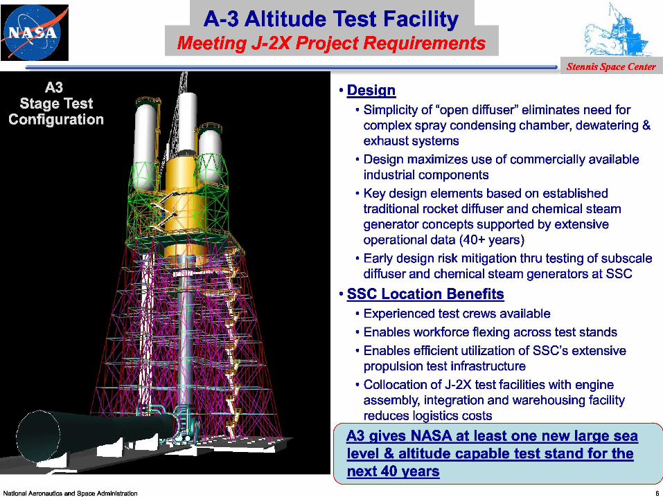
• Design• Simplicity of “open diffuser” eliminates need for
complex spray condensing chamber, dewatering &exhaust systems
• Design maximizes use of commercially availableindustrial components
• Key design elements based on establishedtraditional rocket diffuser and chemical steamgenerator concepts supported by extensiveoperational data (40+ years)
• Early design risk mitigation thru testing of subscalediffuser and chemical steam generators at SSC
• SSC Location Benefits• Experienced test crews available• Enables workforce flexing across test stands• Enables efficient utilization of SSC’s extensive
propulsion test infrastructure• Collocation of J-2X test facilities with engine
assembly, integration and warehousing facilityreduces log istics costs
A3 g ives NASA at least one new large sealevel & altitude ca pable test stand for thenext 40 years
National Aeronautics and Space Administration
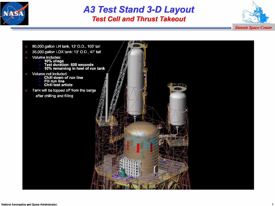
A3 Test Stand 3-D Layout ri^^^ o
Test Cell and Thrust Takeout ^f q
Stennis Space Center
National Aeronautics and Space Administration

A3 Test Stand 3-D Layout ri^^^ o
Engine Deck and Superstructure ^f q
Stennis Space Center
National Aeronautics and Space Administration
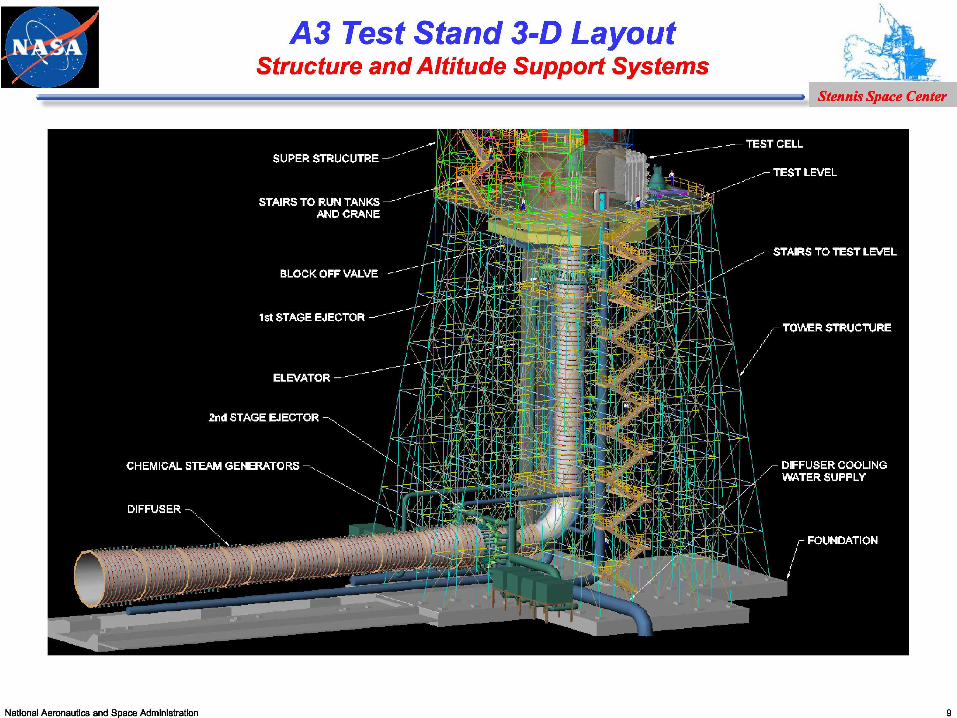
A3 Test Stand 3-D Layout ri^^^ o
Structure and Altitude Support Systems ^f q
Stennis Space Center
National Aeronautics and Space Administration

Steam Supply
♦ A3 Steam System Schematic Diagram
First Stage EjectorSteam Supply LOX Feed
IPA Feed
Water Feed
Steam
2nd Stage Ejector
"- Typical 3-unit CSG Module Output
National Aeronautics and Space Administration 10
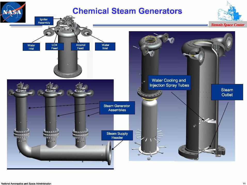
2^^41 Chemical Steam Generators
National Aeronautics and Space Administration

Chemical Steam Generators
Stennis Space Center
♦ CSG cans for facility operation risk mitigate testing have been fabricated andtested
Development CSG CanNational Aeronautics and Space Administration
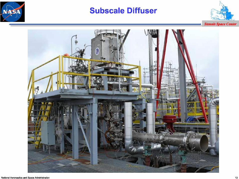
Subscale Diffuser— Stennis Space Center
National Aeronautics and Space Administration
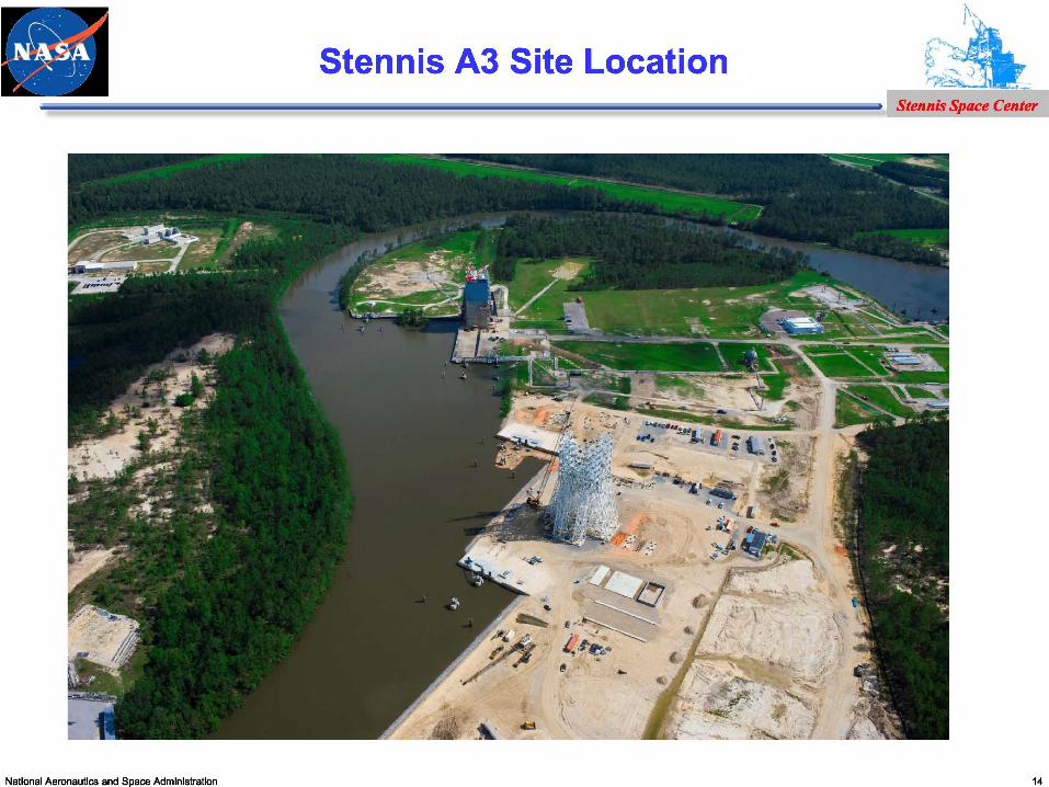
Stennis A3 Site LocationStennis Space Center
National Aeronautics and Space Administration

A3 Construction SiteStennis Space Center
15

A3 Construction SiteStennis Space Center
16

National Aeronautics and Space Administration 17