spotfast® fasteners - pemnet.com · sf-2 pennengineering • spotfast fasteners allows permanent...
TRANSCRIPT
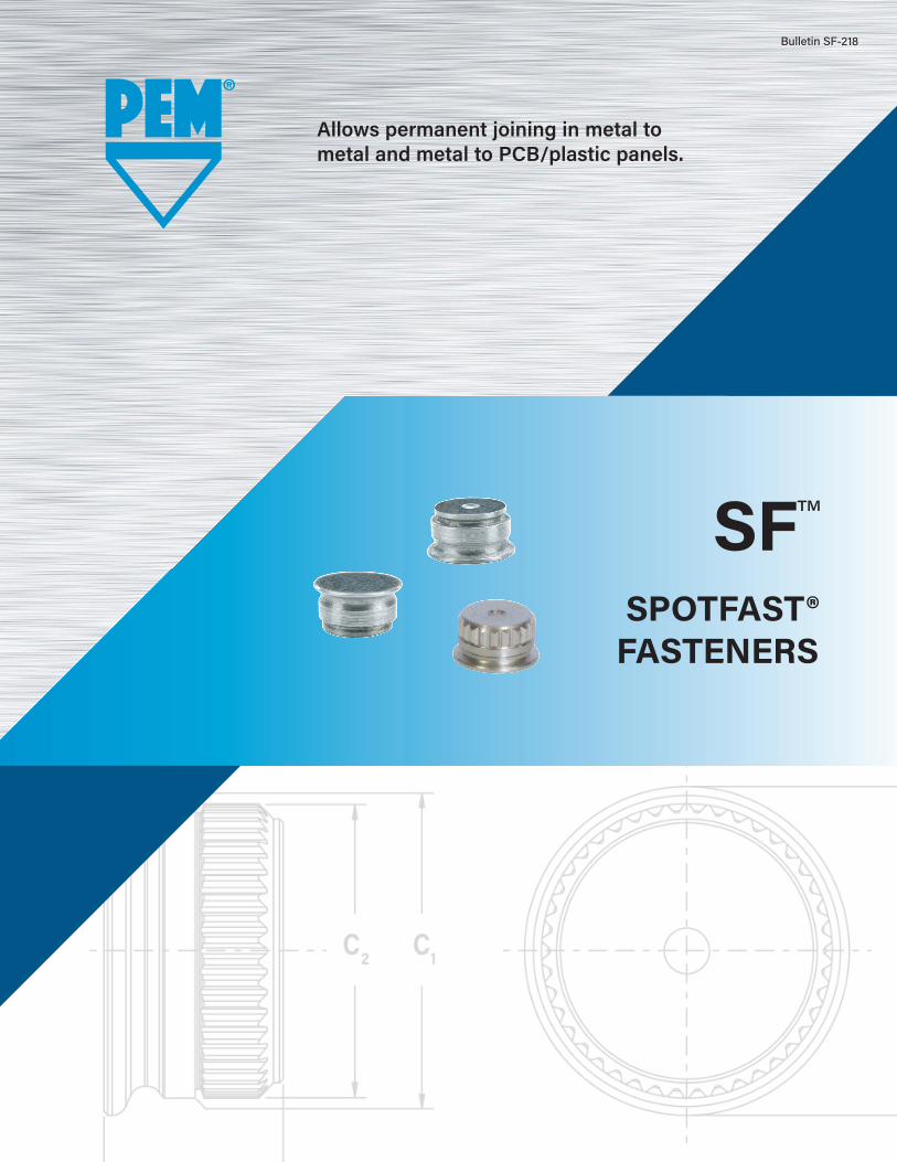
SF™
SPOTFAST®FASTENERS
Allows permanent joining in metal to metal and metal to PCB/plastic panels.
Bulletin SF-218
SF-2 PennEngineering • www.pemnet.com
SPOTFAST® FASTENERS
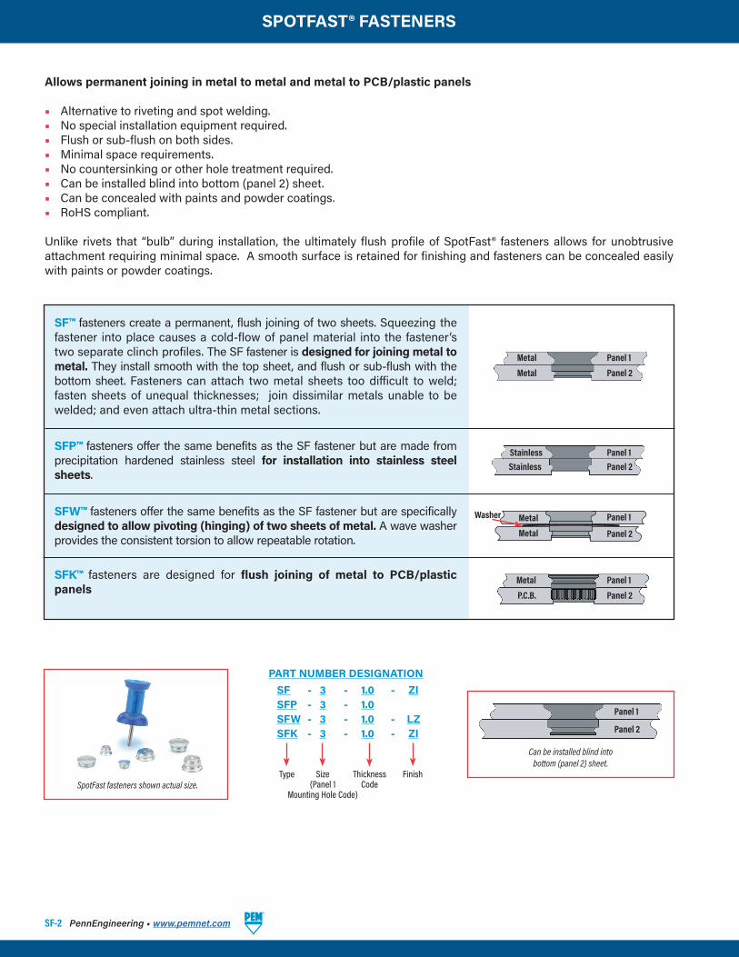
Allows permanent joining in metal to metal and metal to PCB/plastic panels
• Alternative to riveting and spot welding.• No special installation equipment required.• Flush or sub-flush on both sides.• Minimal space requirements.• No countersinking or other hole treatment required.• Can be installed blind into bottom (panel 2) sheet.• Can be concealed with paints and powder coatings.• RoHS compliant.
Unlike rivets that “bulb” during installation, the ultimately flush profile of SpotFast® fasteners allows for unobtrusive attachment requiring minimal space. A smooth surface is retained for finishing and fasteners can be concealed easily with paints or powder coatings.
SFP™ fasteners offer the same benefits as the SF fastener but are made from precipitation hardened stainless steel for installation into stainless steel sheets.
SFW™ fasteners offer the same benefits as the SF fastener but are specifically designed to allow pivoting (hinging) of two sheets of metal. A wave washer provides the consistent torsion to allow repeatable rotation.
SFK™ fasteners are designed for flush joining of metal to PCB/plastic panels
SF™ fasteners create a permanent, flush joining of two sheets. Squeezing the fastener into place causes a cold-flow of panel material into the fastener’s two separate clinch profiles. The SF fastener is designed for joining metal to metal. They install smooth with the top sheet, and flush or sub-flush with the bottom sheet. Fasteners can attach two metal sheets too difficult to weld; fasten sheets of unequal thicknesses; join dissimilar metals unable to be welded; and even attach ultra-thin metal sections.
Type
SF - 3 - 1.0 - ZISFP - 3 - 1.0SFW - 3 - 1.0 - LZSFK - 3 - 1.0 - ZI
FinishThicknessCode
Size(Panel 1
Mounting Hole Code)
PART NUMBER DESIGNATION
SpotFast fasteners shown actual size.
Panel 1
Panel 2
Metal
Metal
Can be installed blind intobottom (panel 2) sheet.
Panel 1
Panel 2
Panel 1
Panel 2
Metal
P.C.B.
Panel 1Panel 2
StainlessStainless
Panel 1
Panel 2
Metal
Metal
Washer

SPOTFAST® FASTENERS
PennEngineering • www.pemnet.com SF-3
P r i m a r y U s e
Type Joining two panels of Joining two panels when Joining a metal panel to a Single point hinging Offers highest corrosion similar or dissimilar metals one or more is stainless steel PCB or plastic panel applications resistance in product family
SF • • (1)
SFP • (1) • • (1) • SFW • (1) • SFK • (1) • • (1)
SF™ fastener installed into unequal thickness sheets. Fastener is smooth with top of panel 1.
SF™ fastener installed sub-flush with panel 2. Fastener will be flush at minimum sheet thickness.
SFW™ fastener offers flush-mounted, smooth pivot point.
(1) Not primary use.
SPOTFAST® FASTENER SELECTOR GUIDE
Sheets as thin as .005” / 0.13 mm may be attached to thicker sheets using a PEM® SpotFast ® fastener. The thin sheet must be panel 1 and the “L” dimension must be equal to or less than the combined panel thicknesses. Consult our Applications Engineering department for more information.
MetalPlastic
SFK™ fastener joining metal to plastic.
METAL TO METAL HINGING APPLICATIONS
METAL TO PCB/PLASTIC
SF-4 PennEngineering • www.pemnet.com
SPOTFAST® FASTENERS
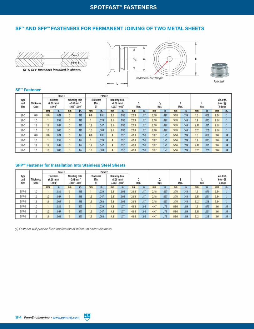
Panel 1 Panel 2 Type Thickness Mounting Hole Thickness Mounting Hole Min. Dist. and Thickness ±0.08 mm / +0.08 mm / Min. +0.08 mm / C1 C2 E L Hole C/L Size Code ±.003” +.003” –.000” (1) +.003” –.000” Max. Max. Max. Max. To Edge mm in. mm in. mm in. mm in. mm in. mm in. mm in. mm in. mm in. SF-3 0.8 0.8 .031 3 .118 0.8 .031 2.5 .098 2.98 .117 2.48 .097 3.53 .139 1.5 .059 2.54 .1
SF-3 1.0 1 .039 3 .118 1 .039 2.5 .098 2.98 .117 2.48 .097 3.76 .148 1.9 .075 2.54 .1
SF-3 1.2 1.2 .047 3 .118 1.2 .047 2.5 .098 2.98 .117 2.48 .097 3.76 .148 2.31 .091 2.54 .1
SF-3 1.6 1.6 .063 3 .118 1.6 .063 2.5 .098 2.98 .117 2.48 .097 3.76 .148 3.12 .123 2.54 .1
SF-5 0.8 0.8 .031 5 .197 0.8 .031 4 .157 4.98 .196 3.97 .156 5.56 .219 1.5 .059 3.6 .14
SF-5 1.0 1 .039 5 .197 1 .039 4 .157 4.98 .196 3.97 .156 5.56 .219 1.9 .075 3.6 .14
SF-5 1.2 1.2 .047 5 .197 1.2 .047 4 .157 4.98 .196 3.97 .156 5.56 .219 2.31 .091 3.6 .14
SF-5 1.6 1.6 .063 5 .197 1.6 .063 4 .157 4.98 .196 3.97 .156 5.56 .219 3.12 .123 3.6 .14
SF™ AND SFP™ FASTENERS FOR PERMANENT JOINING OF TWO METAL SHEETS
SFP™ Fastener for Installation Into Stainless Steel Sheets
Panel 1 Panel 2 Type Thickness Mounting Hole Thickness Mounting Hole Min. Dist. and Thickness ±0.08 mm / +0.08 mm / Min. +0.08 mm / C1 C2 E L Hole C/L Size Code ±.003” +.003” –.000” (1) +.003” –.000” Max. Max. Max. Max. To Edge mm in. mm in. mm in. mm in. mm in. mm in. mm in. mm in. mm in. SFP-3 1.0 1 .039 3 .118 1 .039 2.5 .098 2.98 .117 2.48 .097 3.76 .148 1.9 .075 2.54 .1
SFP-3 1.2 1.2 .047 3 .118 1.2 .047 2.5 .098 2.98 .117 2.48 .097 3.76 .148 2.31 .091 2.54 .1
SFP-3 1.6 1.6 .063 3 .118 1.6 .063 2.5 .098 2.98 .117 2.48 .097 3.76 .148 3.12 .123 2.54 .1
SFP-5 1.0 1 .039 5 .197 1 .039 4.5 .177 4.98 .196 4.47 .176 5.56 .219 1.9 .075 3.6 .14
SFP-5 1.2 1.2 .047 5 .197 1.2 .047 4.5 .177 4.98 .196 4.47 .176 5.56 .219 2.31 .091 3.6 .14
SFP-5 1.6 1.6 .063 5 .197 1.6 .063 4.5 .177 4.98 .196 4.47 .176 5.56 .219 3.12 .123 3.6 .14
SF & SFP fasteners installed in sheets.
Panel 1
Panel 2
Patented.
(1) Fastener will provide flush application at minimum sheet thickness.
SF™ Fastener
C2 C1
L
E
Trademark PEM® Dimple
SPOTFAST® FASTENERS
PennEngineering • www.pemnet.com SF-5
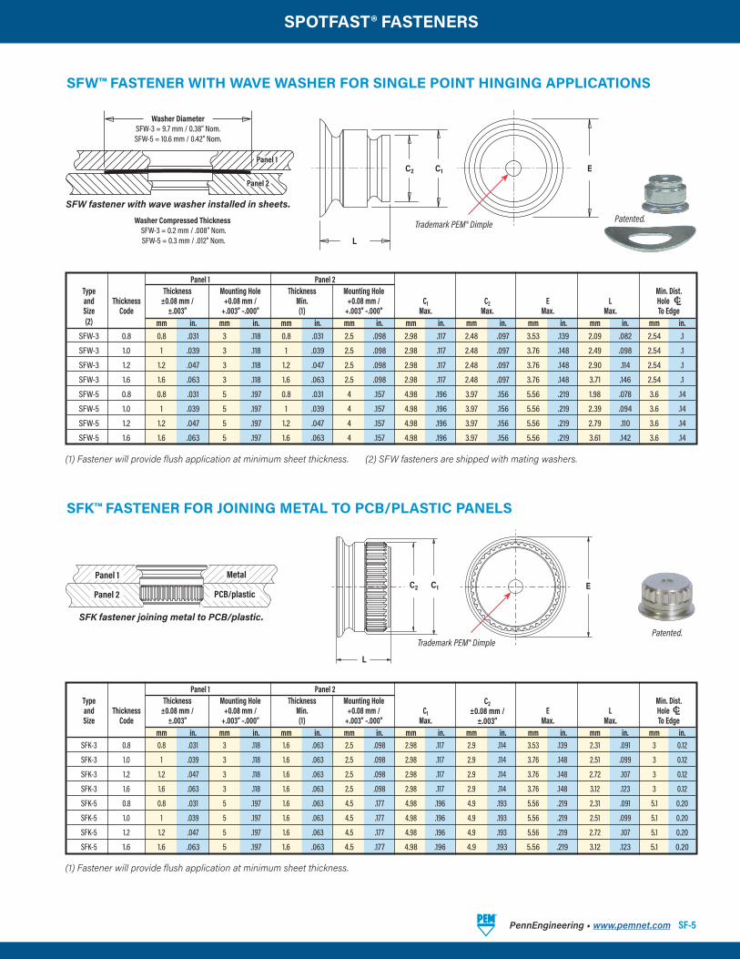
SFK™ FASTENER FOR JOINING METAL TO PCB/PLASTIC PANELS
(1) Fastener will provide flush application at minimum sheet thickness.
(1) Fastener will provide flush application at minimum sheet thickness. (2) SFW fasteners are shipped with mating washers.
Panel 1 Panel 2 Type Thickness Mounting Hole Thickness Mounting Hole Min. Dist. and Thickness ±0.08 mm / +0.08 mm / Min. +0.08 mm / C1 C2 E L Hole C/L Size Code ±.003” +.003” –.000” (1) +.003” –.000” Max. Max. Max. Max. To Edge (2) mm in. mm in. mm in. mm in. mm in. mm in. mm in. mm in. mm in. SFW-3 0.8 0.8 .031 3 .118 0.8 .031 2.5 .098 2.98 .117 2.48 .097 3.53 .139 2.09 .082 2.54 .1
SFW-3 1.0 1 .039 3 .118 1 .039 2.5 .098 2.98 .117 2.48 .097 3.76 .148 2.49 .098 2.54 .1
SFW-3 1.2 1.2 .047 3 .118 1.2 .047 2.5 .098 2.98 .117 2.48 .097 3.76 .148 2.90 .114 2.54 .1
SFW-3 1.6 1.6 .063 3 .118 1.6 .063 2.5 .098 2.98 .117 2.48 .097 3.76 .148 3.71 .146 2.54 .1
SFW-5 0.8 0.8 .031 5 .197 0.8 .031 4 .157 4.98 .196 3.97 .156 5.56 .219 1.98 .078 3.6 .14
SFW-5 1.0 1 .039 5 .197 1 .039 4 .157 4.98 .196 3.97 .156 5.56 .219 2.39 .094 3.6 .14
SFW-5 1.2 1.2 .047 5 .197 1.2 .047 4 .157 4.98 .196 3.97 .156 5.56 .219 2.79 .110 3.6 .14
SFW-5 1.6 1.6 .063 5 .197 1.6 .063 4 .157 4.98 .196 3.97 .156 5.56 .219 3.61 .142 3.6 .14
SFW™ FASTENER WITH WAVE WASHER FOR SINGLE POINT HINGING APPLICATIONS
SFW fastener with wave washer installed in sheets.
SFW-3 = 9.7 mm / 0.38” Nom.SFW-5 = 10.6 mm / 0.42” Nom.
Panel 1
Panel 2
Patented.
Panel 1
Panel 2
Metal
PCB/plastic
SFK fastener joining metal to PCB/plastic.
Panel 1 Panel 2 Type Thickness Mounting Hole Thickness Mounting Hole C2 Min. Dist. and Thickness ±0.08 mm / +0.08 mm / Min. +0.08 mm / C1 ±0.08 mm / E L Hole C/L Size Code ±.003” +.003” –.000” (1) +.003” –.000” Max. ±.003” Max. Max. To Edge mm in. mm in. mm in. mm in. mm in. mm in. mm in. mm in. mm in. SFK-3 0.8 0.8 .031 3 .118 1.6 .063 2.5 .098 2.98 .117 2.9 .114 3.53 .139 2.31 .091 3 0.12
SFK-3 1.0 1 .039 3 .118 1.6 .063 2.5 .098 2.98 .117 2.9 .114 3.76 .148 2.51 .099 3 0.12
SFK-3 1.2 1.2 .047 3 .118 1.6 .063 2.5 .098 2.98 .117 2.9 .114 3.76 .148 2.72 .107 3 0.12
SFK-3 1.6 1.6 .063 3 .118 1.6 .063 2.5 .098 2.98 .117 2.9 .114 3.76 .148 3.12 .123 3 0.12
SFK-5 0.8 0.8 .031 5 .197 1.6 .063 4.5 .177 4.98 .196 4.9 .193 5.56 .219 2.31 .091 5.1 0.20
SFK-5 1.0 1 .039 5 .197 1.6 .063 4.5 .177 4.98 .196 4.9 .193 5.56 .219 2.51 .099 5.1 0.20
SFK-5 1.2 1.2 .047 5 .197 1.6 .063 4.5 .177 4.98 .196 4.9 .193 5.56 .219 2.72 .107 5.1 0.20
SFK-5 1.6 1.6 .063 5 .197 1.6 .063 4.5 .177 4.98 .196 4.9 .193 5.56 .219 3.12 .123 5.1 0.20
C2 C1
L
E
Washer Diameter
SFW-3 = 0.2 mm / .008” Nom.SFW-5 = 0.3 mm / .012” Nom.
Washer Compressed Thickness Patented.
C2 C1
L
E
Trademark PEM® Dimple
Trademark PEM® Dimple
SF-6 PennEngineering • www.pemnet.com
SPOTFAST® FASTENERS
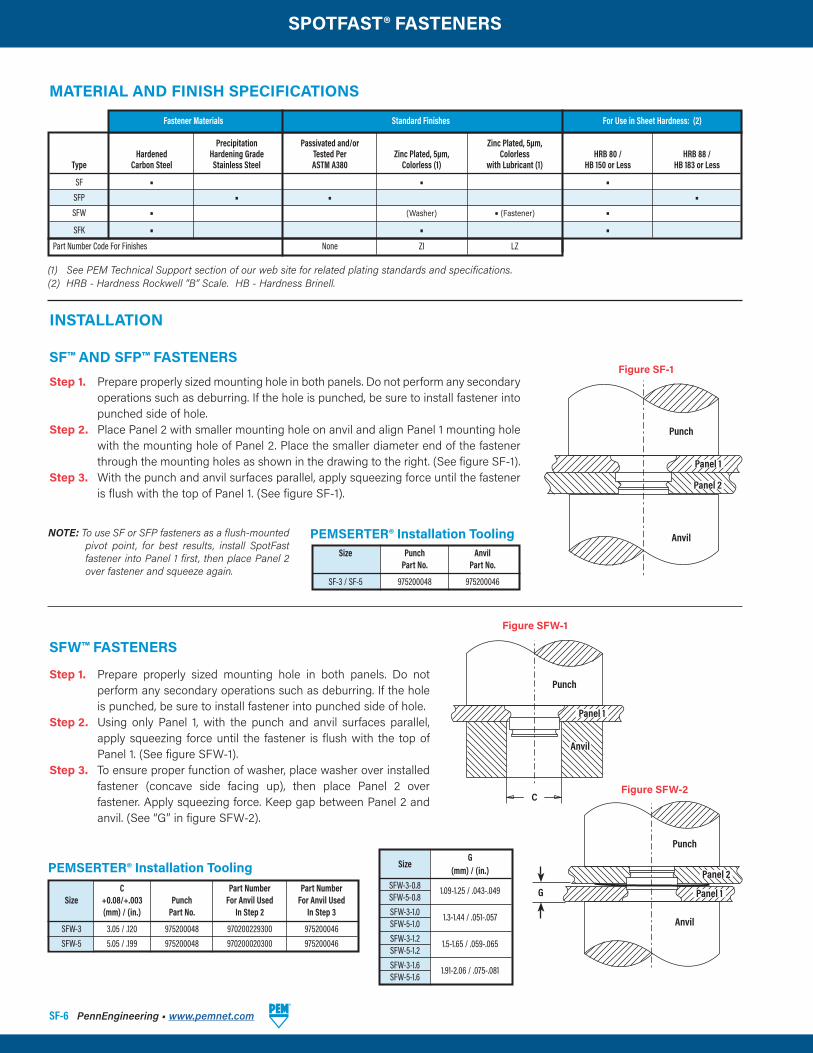
Precipitation Passivated and/or Zinc Plated, 5µm, Hardened Hardening Grade Tested Per Zinc Plated, 5µm, Colorless HRB 80 / HRB 88 / Type Carbon Steel Stainless Steel ASTM A380 Colorless (1) with Lubricant (1) HB 150 or Less HB 183 or Less
SF • • • SFP • • • SFW • (Washer) • (Fastener) • SFK • • • Part Number Code For Finishes None ZI LZ
INSTALLATION
Step 1. Prepare properly sized mounting hole in both panels. Do not perform any secondary operations such as deburring. If the hole is punched, be sure to install fastener into punched side of hole.
Step 2. Place Panel 2 with smaller mounting hole on anvil and align Panel 1 mounting hole with the mounting hole of Panel 2. Place the smaller diameter end of the fastener through the mounting holes as shown in the drawing to the right. (See figure SF-1).
Step 3. With the punch and anvil surfaces parallel, apply squeezing force until the fastener is flush with the top of Panel 1. (See figure SF-1).
Panel 1
Panel 2
Punch
AnvilNOTE: To use SF or SFP fasteners as a flush-mounted pivot point, for best results, install SpotFast fastener into Panel 1 first, then place Panel 2 over fastener and squeeze again.
SF™ AND SFP™ FASTENERS
SFW™ FASTENERS
Step 1. Prepare properly sized mounting hole in both panels. Do not perform any secondary operations such as deburring. If the hole is punched, be sure to install fastener into punched side of hole.
Step 2. Using only Panel 1, with the punch and anvil surfaces parallel, apply squeezing force until the fastener is flush with the top of Panel 1. (See figure SFW-1).
Step 3. To ensure proper function of washer, place washer over installed fastener (concave side facing up), then place Panel 2 over fastener. Apply squeezing force. Keep gap between Panel 2 and anvil. (See “G” in figure SFW-2).
PEMSERTER® Installation Tooling C Part Number Part Number Size +0.08/+.003 Punch For Anvil Used For Anvil Used (mm) / (in.) Part No. In Step 2 In Step 3
SFW-3 3.05 / .120 975200048 970200229300 975200046 SFW-5 5.05 / .199 975200048 970200020300 975200046
C
Punch
Punch
Anvil
Fastener Materials Standard Finishes For Use in Sheet Hardness: (2)
(1) See PEM Technical Support section of our web site for related plating standards and specifications.(2) HRB - Hardness Rockwell “B” Scale. HB - Hardness Brinell.
MATERIAL AND FINISH SPECIFICATIONS
Figure SF-1
Figure SFW-1
Figure SFW-2
Panel 1
Anvil
PEMSERTER® Installation Tooling Size Punch Anvil Part No. Part No.
SF-3 / SF-5 975200048 975200046
G
Panel 2
Panel 1
Size
G (mm) / (in.) SFW-3-0.8
1.09-1.25 / .043-.049 SFW-5-0.8 SFW-3-1.0
1.3-1.44 / .051-.057 SFW-5-1.0 SFW-3-1.2
1.5-1.65 / .059-.065 SFW-5-1.2 SFW-3-1.6
1.91-2.06 / .075-.081 SFW-5-1.6
SPOTFAST® FASTENERS
PennEngineering • www.pemnet.com SF-7
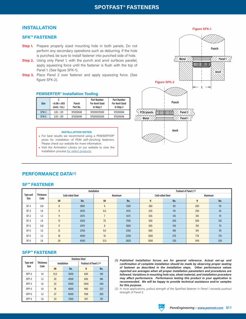
SF™ FASTENER
Stainless Steel Type and Thickness Installation Pushout of Panel 2 (2)
Size Code kN lbs. N lbs.
SFP-3 1.0 13.5 3000 620 140
SFP-3 1.2 20 4500 830 186
SFP-3 1.6 22 5000 1500 340
SFP-5 1.0 18 4000 990 222
SFP-5 1.2 27 6000 1158 260
SFP-5 1.6 33 7500 3117 701
SFP™ FASTENER
Installation Pushout of Panel 2 (2)
Type and Thickness Cold-rolled Steel Aluminum Cold-rolled Steel Aluminum Size Code kN lbs. kN lbs. N lbs. N lbs.
SF-3 0.8 8 1800 6 1350 360 80 200 45
SF-3 1.0 9 2025 6.5 1475 525 115 250 55
SF-3 1.2 11 2475 7 1575 555 125 310 70
SF-3 1.6 13 2925 7.5 1700 920 205 550 125
SF-5 0.8 11 2475 8 1800 625 140 310 70
SF-5 1.0 12 2700 9.5 2150 800 180 515 115
SF-5 1.2 18 4050 10 2250 1200 270 770 170
SF-5 1.6 20 4500 12.5 2825 1500 335 1145 255
INSTALLATION
PERFORMANCE DATA(1)
SFK™ FASTENER
Step 1. Prepare properly sized mounting hole in both panels. Do not perform any secondary operations such as deburring. If the hole is punched, be sure to install fastener into punched side of hole.
Step 2. Using only Panel 1, with the punch and anvil surfaces parallel, apply squeezing force until the fastener is flush with the top of Panel 1. (See figure SFK-1).
Step 3. Place Panel 2 over fastener and apply squeezing force. (See figure SFK-2).
C
Punch
Punch
Anvil
Panel 1Metal
Panel 2PCB/plastic
PEMSERTER® Installation Tooling
(1) Published installation forces are for general reference. Actual set-up and confirmation of complete installation should be made by observing proper seating of fastener as described in the installation steps. Other performance values reported are averages when all proper installation parameters and procedures are followed. Variations in mounting hole size, sheet material, and installation procedure may affect performance. Performance testing this product in your application is recommended. We will be happy to provide technical assistance and/or samples for this purpose.
(2) In most applications, pullout strength of the SpotFast fastener in Panel 1 exceeds pushout strength of Panel 2.
Figure SFK-1
Figure SFK-2
Panel 1Metal
Anvil
C Part Number Part Number Size +0.08/+.003 Punch For Anvil Used For Anvil Used (mm) / (in.) Part No. In Step 2 In Step 3
SFW-3 3.05 / .120 975200048 970200229300 975200046 SFW-5 5.05 / .199 975200048 970200020300 975200046
INSTALLATION NOTES• For best results we recommend using a PEMSERTER®
press for installation of PEM self-clinching fasteners. Please check our website for more information.
• Visit the Animation Library on our website to view the installation process for select products.
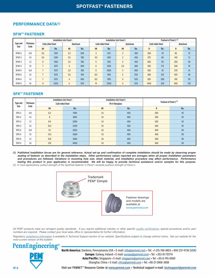
PERFORMANCE DATA(1)
SFK™ FASTENER
(1) Published installation forces are for general reference. Actual set-up and confirmation of complete installation should be made by observing proper seating of fastener as described in the installation steps. Other performance values reported are averages when all proper installation parameters and procedures are followed. Variations in mounting hole size, sheet material, and installation procedure may affect performance. Performance testing this product in your application is recommended. We will be happy to provide technical assistance and/or samples for this purpose.
(2) In most applications, pullout strength of the SpotFast fastener in Panel 1 exceeds pushout strength of Panel 2.
Installation into Panel 1 Installation into Panel 2 Pushout of Panel 2 (2)
Type and Thickness Cold-rolled Steel FR-4 Fiberglass Size Code kN lbs. kN lbs. N lbs.
SFK-3 0.8 6.2 1400 1.8 400 200 45
SFK-3 1.0 8 1800 1.8 400 200 45
SFK-3 1.2 8.9 2000 1.8 400 200 45
SFK-3 1.6 10.2 2300 1.8 400 200 45
SFK-5 0.8 11.1 2500 1.8 400 400 90
SFK-5 1.0 13.5 3000 1.8 400 400 90
SFK-5 1.2 15.6 3500 1.8 400 400 90
SFK-5 1.6 17.8 4000 1.8 400 400 90
Installation into Panel 1 Installation into Panel 2 Pushout of Panel 2 (2)
Type and Thickness Cold-rolled Steel Aluminum Cold-rolled Steel Aluminum Cold-rolled Steel Aluminum Size Code kN lbs. kN lbs. kN lbs. kN lbs. N lbs. N lbs.
SFW-3 0.8 4.5 1010 2.5 560 3 675 2 450 350 78 85 19
SFW-3 1.0 5.5 1240 3.5 780 4.5 1010 2 450 375 84 140 31
SFW-3 1.2 6 1350 3.5 780 5 1125 2 450 500 112 250 56
SFW-3 1.6 7 1575 4 900 6 1350 2.5 560 780 175 340 76
SFW-5 0.8 7 1575 3.5 780 8 1800 4 900 350 78 270 61
SFW-5 1.0 7 1575 3.5 780 8.5 1910 5 1125 380 153 425 96
SFW-5 1.2 7 1575 4 900 8.5 1910 5 1125 925 208 510 115
SFW-5 1.6 9 2025 5 1125 10 2250 5 1125 1450 326 600 135
SFW™ FASTENER
Trademark PEM® Dimple
Fastener drawings and models are available atwww.pemnet.com
All PEM® products meet our stringent quality standards. If you require additional industry or other specific quality certifications, special procedures and/or part numbers are required. Please contact your local sales office or representative for further information.
Regulatory compliance information is available in Technical Support section of our website. Specifications subject to change without notice. See our website for the most current version of this bulletin.
North America: Danboro, Pennsylvania USA • E-mail: [email protected] • Tel: +1-215-766-8853 • 800-237-4736 (USA)Europe: Galway, Ireland • E-mail: [email protected] • Tel: +353-91-751714
Asia/Pacific: Singapore • E-mail: [email protected] • Tel: +65-6-745-0660Shanghai, China • E-mail: [email protected] • Tel: +86-21-5868-3688
Visit our PEMNET™ Resource Center at www.pemnet.com • Technical support e-mail: [email protected]
SPOTFAST® FASTENERS