sponsored by: state energy office national governor’s association, north carolina governor’s...
TRANSCRIPT

Sponsored by: State Energy Office
National Governor’s Association, North Carolina Governor’s Office,
American Institute of Architects NC Dept of Insurance
Conducted by:
The North Carolina Energy Code:
Commercial Requirements
Chris Mathis and AssociatesAsheville, NC
Appalachian State UniversityDept. of Technology &
Energy CenterBoone, NC
Jeff Tiller, PE, [email protected]
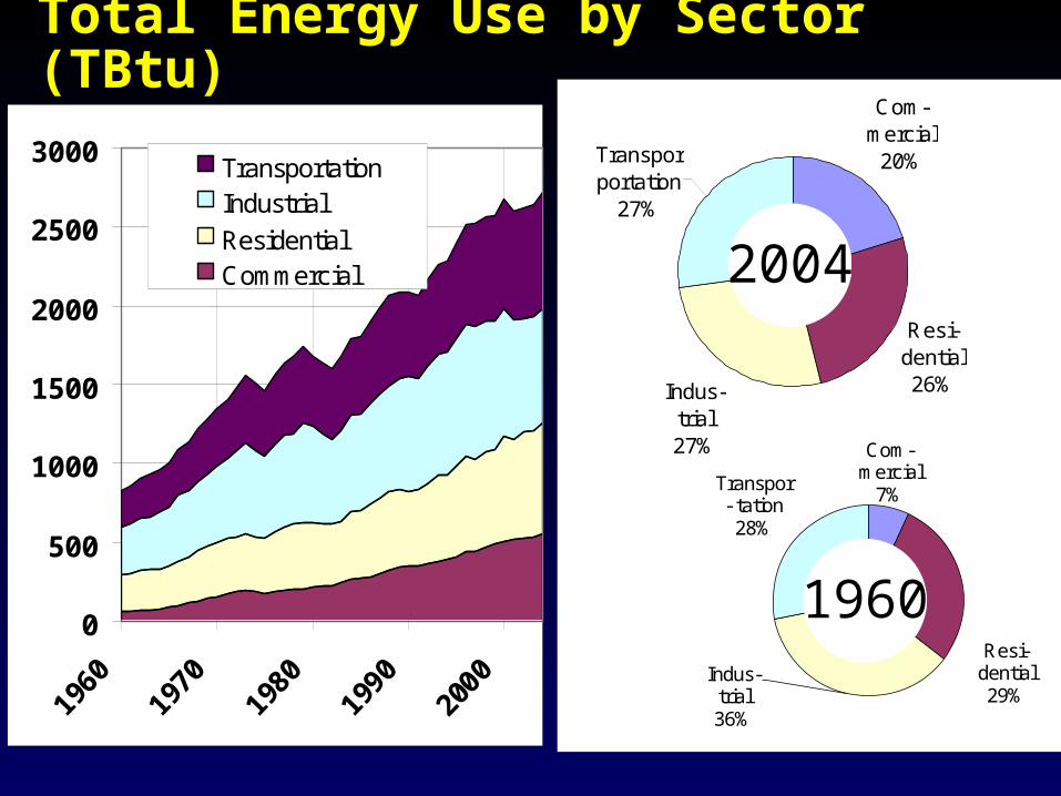
Total Energy Use by Sector (TBtu)
0
500
1000
1500
2000
2500
3000
1960
1970
1980
1990
2000
TransportationIndustrial
ResidentialCommercial
Com- mercial
20%
Resi- dential26%
Transpor- portation
27%
Indus- trial27% Com-
mercial7%
Resi-dential29%
Indus-trial36%
Transpor- tation28%
2004
1960

Structure of 2006 NC Code
Chapter 1: General/Administrative & Enforcement
Chapter 2: Definitions
Chapter 3: Design Conditions
Chapter 4: Residential Energy Efficiency
Chapter 5: Commercial Energy Efficiency
Chapter 6: Referenced Standards
SCOPE
When does the NCECC apply?– Newly conditioned space– New construction in existing buildings– Alterations to existing spaces– Additions– Mixed use buildings– Change in occupancy
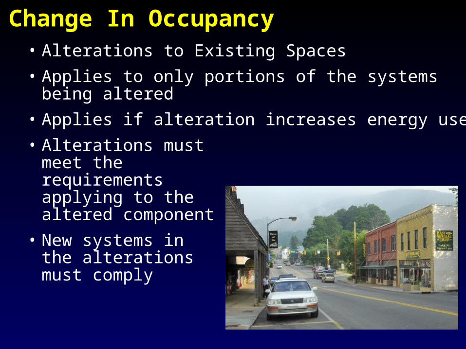
Change In Occupancy• Alterations to Existing Spaces
• Applies to only portions of the systems being altered
• Applies if alteration increases energy use
• Alterations must meet the requirements applying to the altered component
• New systems in the alterations must comply

Two Sets of Requirements – multiple pathways to compliance
• Building Design for All Commercial Buildings– ASHRAE 90.1-2004
in the North Carolina energy code
• Design by Acceptable Practice for Commercial Buildings– Chapter 5 – part of the IECC 2006 –
with local amendments

Typical Commercial Building Energy Consumption Patterns
Equip.
Cooking
Refrgd'n
Lighting
OtherMisc
HVACWater Htg
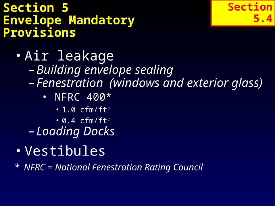
Section 5Envelope Mandatory Provisions
• Air leakage– Building envelope sealing– Fenestration (windows and exterior glass)
• NFRC 400*• 1.0 cfm/ft2
• 0.4 cfm/ft2
– Loading Docks
• Vestibules * NFRC = National Fenestration Rating Council
Section 5.4

Section 5 – Envelope, cont’d Air Leakage
• …..Building envelope shall be sealed, caulked, gasketed or weather-stripped to minimize air leakage.– Seams between panels– Joints between systems– Joints around penetrations

502.3 Basic Requirement: Air Leakage -
Building Envelope Sealing
Caulk between wall and
foundation
Caulk around doors and windows
Caulk between wall arch floor
where floor penetrates wall
Weatherstrip doors
Caulk between wall panels and top and bottom
plates in exterior walls
Caulk at penetrations of utility services
or other service entry through
walls floors and roofs
Caulk between wall panels particularly at
corners and changes in orientation
Caulk between wall and roof
Caulk around penetrations of chimney flue vents or attic
hatches

Major Air Leakage Sites
• Cavities above suspended ceilings
• Plenum return spaces (Highly depressurized)
• Ventilated walls• Equipment tunnels and
chases• Mechanical rooms and
mezzanines• Unconditioned adjacent space
(Storage, warehouse, plant, etc.)• Exhaust and ventilation fans, plus
wind and stack effect, are major driving forces

Is Air Barrier Continuous?
• Brand-new NC building
• Drywall leftoff of exteriorwall abovedropped ceiling
• Building usesabove-ceiling areaas return
• When HVAC operates, entire wall cavity goes to a negative pressure, increasing air leakage, effectively reducing insulation value, and potentially causing moisture problems

Limiting Air Leakage Pathways
• Materials and connections must: stop air flow withstand jobsite abuses withstand forces of wind and
pressure• Penetrations must be sealed
plumbing, wiring, communications ductwork windows and doors
• Functional penetrations, such as air intakes for exhaust fans, must be dampered
• Vestibules (5 Stories or more, with exceptions)

Section 5 – Envelope -- VestibulesRequired at building entrances
Self closing doors
Exceptions:
a. Building entrances with revolving doors.
b. Doors not used as a building entrance.
c. Doors opening directly from a dwelling unit.
d. Building entrances in buildings located in climate zone 1 or 2.
e. Building entrances in buildings located in climate zone 3 or 4 that are less than four stories above grade and less than 10,000 ft2 in area.
f. Building entrances in buildings located in climate zone 5, 6, 7, or 8 that are less than 1,000 ft2 in area.
g. Doors that open directly from a space that is less than 3,000 ft2 in area and is separate from the building entrance.

Section 5 - Prescriptive Requirements, Building Envelope
VentilatedAttic
SemiheatedStorage
ConditionedSpace
VentilatedCrawlspace
Exterior Envelope
AtticSemi-Exterior Envelope
UnconditionedSpace
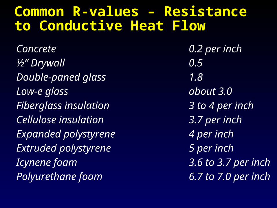
Common R-values – Resistance to Conductive Heat Flow
Concrete 0.2 per inch½” Drywall 0.5Double-paned glass 1.8Low-e glass about 3.0Fiberglass insulation 3 to 4 per inchCellulose insulation 3.7 per inchExpanded polystyrene 4 per inchExtruded polystyrene 5 per inchIcynene foam 3.6 to 3.7 per inchPolyurethane foam 6.7 to 7.0 per inch

2009 IECC Climate Zones:Zones 4 and Below Don’t Require Wall Vapor Barriers (Only NW Mountains need one)

2009 NC Energy Code Climate Zones
Zone 3&4 – No VB
Zone 5 – VB Required

NORTH CAROLINA ZONESZone 3 exceptZone 4AlamanceAlexanderBertieBuncombeBurkeCaldwellCaswellCatawbaChathamCherokeeClayClevelandDavieDurhamForsythFranklinGates
GrahamGranvilleGuilfordHalifaxHarnettHaywoodHendersonHertfordIredellJacksonLeeLincolnMaconMadisonMcDowellNashNorthamptonOrangePerson
PolkRockinghamRutherfordStokesSurrySwainTransylvaniaVanceWakeWarrenWilkesYadkinZone 5AlleghanyAsheAveryMitchellWataugaYancey

NC Energy Code Chapter 5 Prescriptive
Zone 3 Zone 4 Zone 5Roofs Insulation entirely above deck
R-15, c.i. R-15, c.i. R-20, c.i.
Metal buildings (with R-5 thermal blocks)
R-19 R-19 R-19
Attic and other R-30 R-30 R-30Walls, Above Grade Mass R-5.7 c.i. R-5.7 c.i. R-7.6 c.i. Metal building R-13 R-13 R-13+R-13 Metal framed R-13 R-13 R-13+R-3.8 c.i. Wood framed and other R-13 R-13 R-13Walls, Below Grade NR NR NRFloors
Mass R-5 c.i. R-10 c.i. R-10 c.i.
J oist/ Framing R-19 R-19 R-19
Slab-on-Grade Floors
Unheated slabs NR NR NR
Heated slabs R-7.5
(12 in vert)
R-7.5
(12 in vert)
R-7.5
(24 in vert)
Climate Zone

Roof Insulation Requirements: IECC 2003 (Chapter 8 of current code)
Roofs 3 4 5 Insulation entirely above deck R-15, c.i. R-15, c.i. R-20, c.i. Metal buildings (with R-5 thermal blocks) R-19 R-19 R-19 Attic and other R-30 R-30 R-30
Roofs for Metal Buildings:
Climate Zone
R-19 + R-10 Filled cavity roof -- Thermal blocks are a minimum, R-5 of rigid insulation, which extends 1 in. beyond the width of the purlin on each side, perpendicular to the purlin. This construction is R-10 insulation batts draped perpendicularly over the purlins, with enough looseness to allow R-19 batt to be laid above it, parallel to the purlins. Thermal blocks are then placed above the purlin/ batt, and the roof deck is secured to the purlins. In the metal building industry, this is known as the “sag and bag” insulation system.
R-19: Standing seam with single insulation layer. Thermal blocks are a minimum R-5 of rigid insulation, which extends 1 in. beyond the width of the purlin on each side, perpendicular to the purlin. This construction R-19 insulation batts draped perpendicularly over the purlins. Thermal blocks are then placed above the purlin/ batt, and the roof deck is secured to the purlins.

Roof Insulation Requirements:ASHRAE 90.1-2004 (Chapter 7 of current code and Chapter 5, section 501 of new code)
Table 5.5-3 ASHRAE 90.1-2004 Nonresidential Residential Semiheated
ASHRAE 90.1-2004 (Chapter 5)NonresidentialRoof Zone 3 Zone 4 Zone 5Insulation Entirely above Deck R-15 c.i.* R-15 c.i.* R-15 c.i.*Metal Building R-19.0 R-19.0 R-19.0Attic and Other R-30.0 R-30.0 R-30.0
ResidentialRoof Zone 3 Zone 4 Zone 5Insulation Entirely above Deck R-15.0 c.i. R-15.0 c.i. R-15.0 c.i.Metal Building R-19.0 R-19.0 R-19.0Attic and Other R-38.0 R-38.0 R-38.0
SemiheatedRoof Zone 3 Zone 4 Zone 5Insulation Entirely above Deck R-4.0 c.i. R-4.0 c.i. R-5.0 c.i.Metal Building R-10.0 R-10.0 R-10.0Attic and Other R-13.0 R-13.0 R-19.0* c.i. = continuous insulation -- typically foam

Building Envelope Example: Roofs
No longer counts: Batts over suspended ceiling tiles

Inspection is Critically Important!
• Insulation specification was R-30 foam on roof deck according to the plans (and HVAC design)
• The 2.5 inches found installed in the field would only provide about R-15
2.5”

Commercial Wall Insulation Requirements: IECC 2006 (Chapter 5 of new code)
Walls, Above Grade 3 4 5
Mass R-5.7 c.i. R-5.7 c.i. R-7.6 c.i. Metal building R-13 R-13 R-13+R-13 Metal framed R-13 R-13 R-13+R-3.8 c.i. Wood framed and other R-13 R-13 R-13Walls, Below Grade NR NR NR
Walls for Metal Buildings:
R-13 + R-13 Double insulation layer: The first layer of R-13 insulation batts is installed continuously perpendicular to the girts, and is compressed as the metal skin is attached to the girts. The second layer of R-13 insulation batts is installed within the framing cavity.
Climate Zone
R-13 Single insulation layer: The first layer of R-13 insulation batts is installed continuously perpendicular to the girts and is compressed as the metal skin is attached to the girts.

Steel Framing and Insulation

Metal Framing Effects
• Thermal bridging effect of metal framing must be accounted for in calculating U-factors
Outside Air Film
1- inch Exterior sheathing (R-3.8) with Stucco
2 x 4 Metal Studs with R-13 in the Cavity
1/2 in. Gypsum Board
Inside Air Film

Steel Framed Walls

U-factors for Metal Stud Walls
Nominal R-value
Effective R-value
U-factor Continuous Insulated Sheathing
1/2" EPS 5/8" Poly-Iso 1" XPSR-2.0 R-4.0 R-5.0
2 x 4 Metal Framing at 16 inches on Center (3.5 in cavity depth)None (0.0) 0.352 0.207 0.146 0.128R-11 (5.5) 0.132 0.105 0.087 0.080R-13 (6.0) 0.124 0.100 0.083 0.077R-15 (6.4) 0.118 0.096 0.080 0.074
2 x 4 Metal Framing at 24 inches on Center (3.5 in cavity depth)R-11 (6.6) 0.116 0.094 0.079 0.073R-13 (7.2) 0.108 0.089 0.075 0.070R-15 (7.8) 0.102 0.084 0.072 0.067

Effective R-value of 2x4 Metal Framed Walls (16” o.c.)
02468
101214161820
R-0.5 R-2.5 R-3.4 R-5.0 R-10.0
OSB/ Drywall
1/2" XPS 1/2" Poly-Iso
1" XPS 2" XPS
R-15R-13R-11None
Sheathing R-valueOSB/ Drywall 8.11/2" XPS 9.51/2" Poly-Iso 11.51" XPS 12.52" XPS 17.5
Effective R-Value of 2x4 Metal Framed Wall with R-
13 Batt Insulation

Wall Insulation

How about now?

Typical? Non-Compliant!

Concrete Block Walls
• Concrete Masonry Units– Insulation-filled CMU
used to comply
– IECC 2006:
“The R-value of integral
insulation installed in
concrete masonry units
(CMU) shall not be used
in determining
compliance with Table
502.2(1)”

Glazing Area Percentage
• Glazing percentage to Above Grade Wall– Gross window area /
gross wall area – Gross wall area
includes• Above-grade walls• Band joist and
subfloor between floors
• Area of all doors and windows

Windows - SHGC
• Solar Heat Gain Coefficient– Requirements dependent
on projection factor
– National Fenestration Rating Council (NFRC) tested
– Default SHGC range diagrams
– SHGC = SC x .87
Solar Heat Gain Coefficient
Projection Factor (PF)

NFRC Label

IECC 2006 Commercial Glazing Requirements (new code)
Vertical Fenestration (40% maximum of above-grade walls)Required U-factors Zone 3 Zone 4 Zone 5 Framing materials other than metal 0.65 0.4 0.35Metal framed windows with or without thermal break Curtain Wall/ Storefront 0.6 0.5 0.45 Entrance Door 0.9 0.85 0.8 All Other 0.65 0.55 0.55Solar Heat Gain Coefficient SHGC: Projection Factor <0.25 0.25 0.4 0.4 SHGC: 0.25 to 0.50 0.33 NR NR SHGC: >= 0.5 0.4 NR NR

ASHRAE 90.1 Fenestration Requirements for Climate Zones 3 and 4
ASHRAE 90.1-2004 (Chapter 5)Fenestration Values for Climate Zone 3Window-Wall Ratio
Nonresidential Residential Semiheated
0-10.0% Uf ixed-0.57, SHGCall-0.39 Uf ixed-0.57, SHGCall-0.39 Uf ixed-1.22, SHGCall- NR
Uoper-0.67, SHGCnorth-0.49 Uoper-0.67, SHGCnorth-0.49 Uoper-1.27, SHGCnorth- NR
10.1-20.0% Uf ixed-0.57, SHGCall-0.25 Uf ixed-0.57, SHGCall-0.39 Uf ixed-1.22, SHGCall- NR
Uoper-0.67, SHGCnorth-0.49 Uoper-0.67, SHGCnorth-0.49 Uoper-1.27, SHGCnorth- NR
20.1-30.0% Uf ixed-0.57, SHGCall-0.25 Uf ixed-0.57, SHGCall-0.25 Uf ixed-1.22, SHGCall- NR
Uoper-0.67, SHGCnorth-0.39 Uoper-0.67, SHGCnorth-0.39 Uoper-1.27, SHGCnorth- NR
30.1-40.0% Uf ixed-0.57, SHGCall-0.25 Uf ixed-0.57, SHGCall-0.25 Uf ixed-1.22, SHGCall- NR
Uoper-0.67, SHGCnorth-0.39 Uoper-0.67, SHGCnorth-0.39 Uoper-1.27, SHGCnorth- NR
40.1-50.0% Uf ixed-0.46, SHGCall-0.19 Uf ixed-0.46, SHGCall-0.19 Uf ixed-0.98, SHGCall- NR
Uoper-0.47, SHGCnorth-0.26 Uoper-0.47, SHGCnorth-0.26 Uoper-1.02, SHGCnorth- NR
Uf ixed = U-value of fixed windows; Uoper = U-value of operable windows
SHGCall = Solar Heat Gain Coefficient of all windows
SHGCnorth = Solar Heat Gain Coefficient of north windows
Fenestration Values for Climate Zone 4Window-Wall Ratio
Nonresidential Residential Semiheated
0-10.0% Uf ixed-0.57, SHGCall-0.39 Uf ixed-0.57, SHGCall-0.39 Uf ixed-1.22, SHGCall- NR
Uoper-0.67, SHGCnorth-0.49 Uoper-0.67, SHGCnorth-0.49 Uoper-1.27, SHGCnorth- NR
10.1-20.0% Uf ixed-0.57, SHGCall-0.39 Uf ixed-0.57, SHGCall-0.39 Uf ixed-1.22, SHGCall- NR
Uoper-0.67, SHGCnorth-0.49 Uoper-0.67, SHGCnorth-0.49 Uoper-1.27, SHGCnorth- NR
20.1-30.0% Uf ixed-0.57, SHGCall-0.39 Uf ixed-0.57, SHGCall-0.39 Uf ixed-1.22, SHGCall- NR
Uoper-0.67, SHGCnorth-0.49 Uoper-0.67, SHGCnorth-0.49 Uoper-1.27, SHGCnorth- NR
30.1-40.0% Uf ixed-0.57, SHGCall-0.39 Uf ixed-0.57, SHGCall-0.39 Uf ixed-1.22, SHGCall- NR
Uoper-0.67, SHGCnorth-0.49 Uoper-0.67, SHGCnorth-0.49 Uoper-1.27, SHGCnorth- NR
40.1-50.0% Uf ixed-0.46, SHGCall-0.25 Uf ixed-0.46, SHGCall-0.25 Uf ixed-0.98, SHGCall- NR
Uoper-0.47, SHGCnorth-0.36 Uoper-0.47, SHGCnorth-0.36 Uoper-1.02, SHGCnorth- NR
Note: ASHRAE 90.1-2004 is an option for the current and new codes
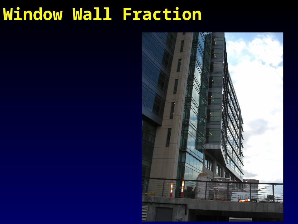
Window Wall Fraction

1/28/2008 Mathis Consulting Company Page 42
Section 6 – HVAC Key Concepts
• Goal – a system which minimizes system losses and utilizes free heating and cooling
• Scope and Compliance Paths
• Establish minimum equipment efficiencies
• Establish a min. level of control for systems
• Establish minimum levels of construction and insulation of systems.
• Simplified Approach/Prescriptive Path
• Submittals

Example; 25-ton: Cooling Efficiency
Cooling efficiency:
25 tons = 300,000 Btuh

Example; 25 ton: Heating
Heating efficiency:
25 tons = 300,000 Btuh
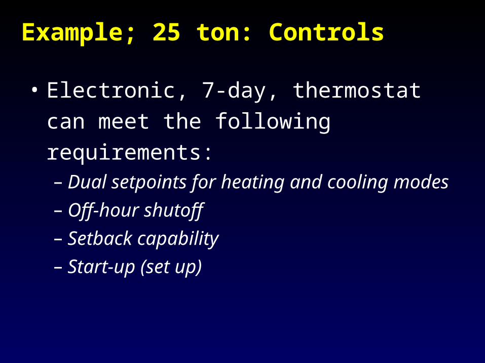
Example; 25 ton: Controls
• Electronic, 7-day, thermostat can meet the
following requirements:– Dual setpoints for heating and cooling modes
– Off-hour shutoff
– Setback capability
– Start-up (set up)
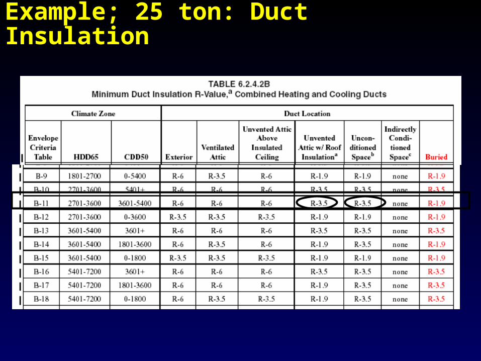
Example; 25 ton: Duct Insulation
Example; 25 ton: Ducts
• Table 6-D in User Manual
• R-3.5: 1-inch duct liner, fiberboard, duct board, flex duct; 1.5-inch mineral fiber duct wrap
• R-6.0: 1.5-inch duct liner, fiberboard, duct board, flex duct; 2.5-inch flex duct, mineral fiber duct wrap
• R-8.0: 2-inch duct liner, fiberboard, duct board, flex duct; 3-inch flex duct, mineral fiber duct wrap
• Duct Sealing Required (to be discussed later)

Example; 25 ton: Other
• Air Balancing – add note to the design drawings or specs calling for balancing according to ASHRAE 111, NEBB, AABCm or other industry-recognized standard
• Since no fan exceeds 300 cfm, a backdraft damper is not required per 6.2.3.3.3

ASHRAE / IESNA 90.1-2001
HVAC Mandatory Provisions
• Applies to the Prescriptive Path and the Energy Cost Budget method
• Requirements address…– Life cycle cost analysis– Equipment efficiencies– Load calculations– Controls– Construction and insulation– Completion requirements

Section 9Lighting General– Scope
• Applies to lighting for:
– Interior spaces
– Exterior building features (facades, roofs, entrances, exits, loading docks, canopies)
– Exterior building grounds provided thru the building’s electrical service

1/28/2008 Mathis Consulting Company Page 57
Occupancy Sensors
• For high usage areas with irregular schedules
• Applications– Private offices– Classrooms– Conference rooms– Break rooms– Restrooms
Section 9.4.1.2

Interior Lighting Controls
• Lighting controls required for each area enclosed by ceiling height partitions
• Switch locations– In view of lights– “On” or “off” indication from
remote location– Occupancy sensor

Interior Lighting Controls
Exceptions– Emergency/security
lighting– Stairway or corridor
lighting for egress

Guest Rooms
• Master switch required at entry
•Standard Room •Suite
•$$
•$$
•$$•$$
•$$
Exterior Lighting Controls
• Automatic switching or photocell controls shall be provided for all exterior lighting not intended for 24-hour operation.
• Automatic time switches shall have a combination– Seven-day and seasonal daylight program
schedule adjustment– A minimum 4-hour power backup

Tandem Wiring
• Exceptions– Luminaires with electronic high-frequency ballasts– Luminaires not on same switch controls or not in the
same area
•Center to Center

Exit Signs
• Internally illuminated exit signs shall not exceed 5 Watts per side
•Section 805.4

Lighting Power Densities Using the Building Area Method
Building Area Typea Lighting Power
Density (Watt/ft2)Automotive Facility 1.5Convention Center 1.4Court House 1.4Dining: Bar, Lounge/ Leisure 1.5Dining: Cafeteria/ Fast Food 1.8Dining: Family 1.9Dormitory 1.5Exercise Center 1.4Gymnasium 1.7Hospital/Health Care 1.6Hotel 1.7Library 1.5Manufacturing Facility 2.2Motel 2.0Motion Picture Theater 1.6
Office 1.3Parking Garage 0.3Penitentiary 1.2Performing Arts Theater 1.5Police/Fire Station 1.3Post Office 1.6Religious Building 2.2Retail 1.9School/University 1.5Sports Arena 1.5Town Hall 1.4Transportation 1.2Warehouse 1.2

Energy-Efficient Lighting Sources

Total Connected Power
• Total connected lighting wattage includes:– Lamp wattage– Ballast wattage
• Sources of bulb/ballast wattages– Manufacturer’s literature– Industry default tables
• Exceptions– Specialized medical, dental, and research lighting– Professional sports arena playing field lighting– Display lighting for gallery exhibits, museums, and monuments– Guest room lighting in hotels, motels, boarding houses, or similar
buildings– Emergency lighting automatically off during normal building
operation

Does the Building Comply?
• Determine the total connected power in watts for the proposed lighting
• Determine the interior lighting power budget for the entire building or space
• Building complies if:– Interior lighting power budget - total connected
power 0
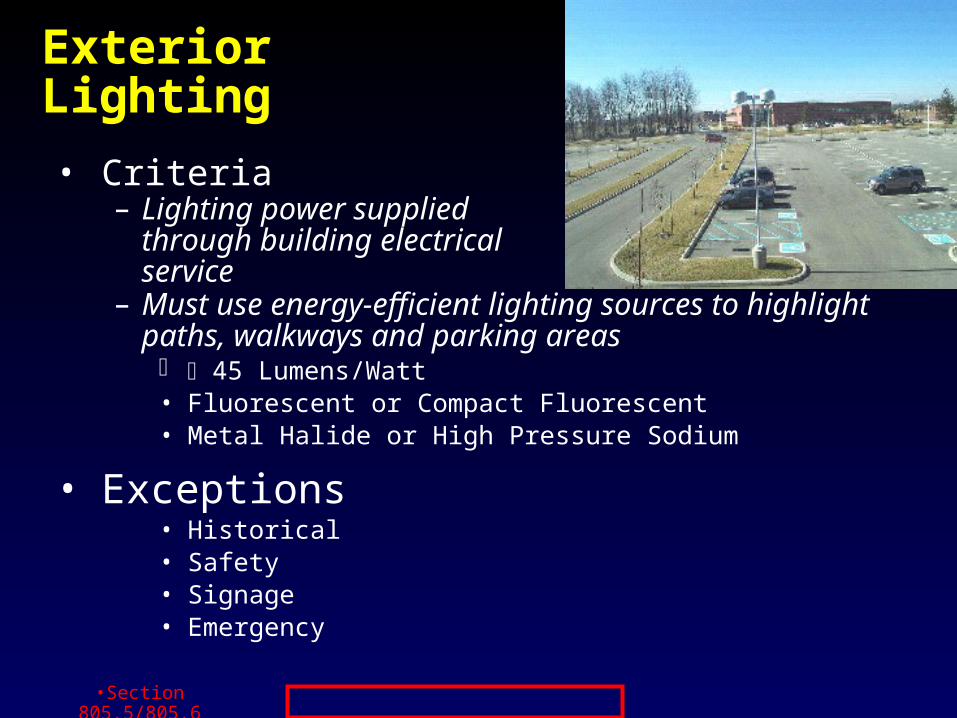
Exterior Lighting
• Criteria– Lighting power supplied
through building electrical service
– Must use energy-efficient lighting sources to highlight paths, walkways and parking areas 45 Lumens/Watt• Fluorescent or Compact Fluorescent• Metal Halide or High Pressure Sodium
• Exceptions• Historical• Safety• Signage• Emergency
•Section 805.5/805.6

1/28/2008 Mathis Consulting Company Page 69
Section 11Energy Cost Budget Method
• Alternative to prescriptive method except buildings with no mechanical systems
• Based on overall building performanceexpressed as “energy cost budget”
• Mandatory Provisions all must be met
• Budget (or baseline) based on prescriptive measures
• Allows trade-offs between measures
• Useful for optimizing design
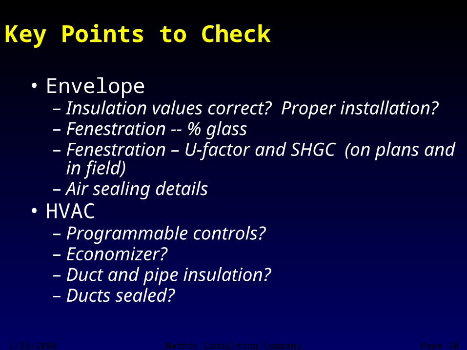
Key Points to Check
• Envelope– Insulation values correct? Proper installation?– Fenestration -- % glass– Fenestration – U-factor and SHGC (on plans and in
field)– Air sealing details
• HVAC– Programmable controls?– Economizer?– Duct and pipe insulation?– Ducts sealed?
1/28/2008 Mathis Consulting Company Page 70
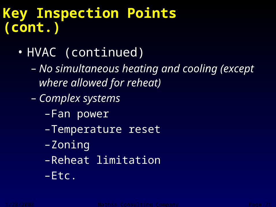
Key Inspection Points (cont.)
• HVAC (continued)– No simultaneous heating and cooling (except where
allowed for reheat)– Complex systems
–Fan power–Temperature reset–Zoning–Reheat limitation–Etc.
1/28/2008 Mathis Consulting Company Page 71

Key Inspection Points (cont.)
• Lighting– If most lamps are not T-8 fluorescent or more efficient
lamps, need to check– Check controls -- occupancy and daylighting controls– Exit signs– Exterior lighting efficiency and controls
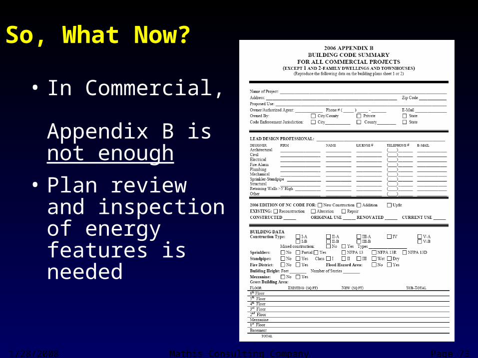
So, What Now?
• In Commercial, Appendix B is not enough
• Plan review and inspection of energy features is needed
1/28/2008 Mathis Consulting Company Page 73

ASHRAE 90.1: Advanced Design Guide – Office Building
Roof Zone 4 Zone 4Insulation Entirely above Deck R-15 c.i.* R-20 c.i.*Metal Building R-19.0 R-13 + 19Attic and Other R-30.0 R-38
Walls, Above GradeMass R-5.7 c.i. R-11.4 c.i.Metal Building R-13 R-13Steel Framed R-13 R-13+R-7.5Wood Framed and Other R-13 R-13Below Grade Wall NR NR
FloorsMass R-8.3 c.i. R-8.3 c.i.Steel Joist R-30 R-30Wood Framed and Other R-30 R-30
Advanced Design Guide
ASHRAE 90.1 2004

ASHRAE 90.1: Advanced Design Guide – Office Building
Fenestration Values for Climate Zone 4
0-10.0% Ufixed-0.57, SHGCall-0.39 Up to 40% of wall area
Uoper-0.67, SHGCnorth-0.49 U-0.42
10.1-20.0%
Ufixed-0.57, SHGCall-0.39 SHGC - 0.46
Uoper-0.67, SHGCnorth-0.49 Area of north glass * SHGCn +
20.1-30.0%
Ufixed-0.57, SHGCall-0.39 Area of south glass * SHGCs >
Uoper-0.67, SHGCnorth-0.49 Area of east glass * SHGCe +
30.1-40.0%
Ufixed-0.57, SHGCall-0.39 Area of west glass * SHGCw
Uoper-0.67, SHGCnorth-0.49 South, east, west has overhang
40.1-50.0%
Ufixed-0.46, SHGCall-0.25
Uoper-0.47, SHGCnorth-0.36
Window-Wall Ratio
ASHRAE 90.1 2004 Advanced Design Guide

ASHRAE 90.1: Advanced Design Guide – Office Building
1.30 Watts/. Sq ft 0.90 Watts/ sq ft90 lumen/ watt linear fluorescentDimmable fixture within 12 ft of N/S window wall or within 8 ft of skylight edgeAuto-off in all unoccupied roomsReflectance of 80% on ceilings, 70% on walls and vertical partitions
ASHRAE 90.1 2004 Advanced Design GuideInterior Lighting

ASHRAE 90.1: Advanced Design Guide – Office Building
0-65 kBtuh 10 SEER 13 SEER65-135 kBtuh 10.3 EER/ 11.2 IPLV 11 EER/ 11.4 IPLV135-240 kBtuh 9.7 EER/ 11.2 IPLV 10.8 EER/ 11.2 IPLV> 240 kBtuh 9.5 EER/ 11.2 IPLV 10 EER/ 10.4 IPLV
FurnacesAll sizes 80% AFUE 80% AFUE
Heat pumps0-65 kBtuh 10 SEER/ 6.8 HSPF 13 SEER/ 7.7 HSPF65-135 kBtuh 10.1 EER 10.6 EER/ 11 IPLV>135 kBtuh 9.3 EER/ 9.2 IPLV (>240) 10.1 EER/ 11 IPLV
Other Economizers -- depend Economizers > 54 kBtuhVentilation controls Motorized control with optional CO2 sensorsSealed ducts Sealed ducts
81% gas instantaneous water htrEF > 99%
ASHRAE 90.1 2004 Advanced Design GuideCooling