split-ring resonator arrays for electromagnetic energy ... · split-ring resonator arrays for...
TRANSCRIPT

Progress In Electromagnetics Research B, Vol. 62, 167–180, 2015
Split-Ring Resonator Arrays for Electromagnetic Energy Harvesting
Thamer S. Almoneef and Omar M. Ramahi*
Abstract—By virtue of their ability to resonate at a wavelength much larger than the maximumdimension, Split-Ring Resonator (SRR) cells can be densely stacked to create energy harvesting arrayshaving per-unit-area power efficiency higher than a single SRR cell. While the concept of usingmetamaterial particles for electromagnetic energy harvesting had been demonstrated in our earlierwork, the overall efficiency of an SRR array in comparison to classical antenna arrays is fundamental tothe viability of this technology. In this work, we focus on a comparative study based on numerical full-wave simulations where an array of SRRs is compared to an array of microstrip antennas. We show thatan SRR array can provide significant enhancement in power efficiency and bandwidth in comparison tothe classical microstrip patch antenna. Experimental validation is provided showing SRR arrays canprovide significant energy-absorption enhancement.
1. INTRODUCTION
It could be argued that Wireless Power Transfer (WPT) dates back to 1888 when Heinrich Hertzdemonstrated electromagnetic wave propagation in free space [1]. Hertz used half-wavelength dipolesoperating at 500 MHz along with parabolic reflectors for transmitting and receiving electromagneticenergy. At the turn of the 20th century, experiments on the concept of WPT were conducted by NickolaTesla who built a gigantic coil resonating at 150 kHz. The coil was then excited with low frequencypower source of 300 kW. Tesla’s coil succeeded in lighting 200 light bulbs placed 42 km away [2]. Tesla’swork intrigued many researchers in Japan [3] and the US [4]. It was not until the 1950s that the WPTwas revisited with the development of high power microwave tubes by the Raytheon Company. Thesetubes were considered essential for transmitting efficient high power at GHz frequencies. In 1963, Brownand his colleagues demonstrated the first complete and efficient WPT system. A horn antenna operatingat 2.45 GHz with power levels of 400 W was used to transmit microwave energy. At the receiving end,a diagonal horn antenna was used to collect the microwave energy, which was then converted back toDC by means of thermionic diodes. Conversion efficiency of only 50% was realized [1, 5].
In 1968, Glasser proposed a concept to use rectennas to harvest energy from space in what wastermed as Space Solar Power (SSP) [6]. In SSP, solar energy is converted to electricity using arrays ofsolar cells placed 22,300 miles above the equator. Then the collected power is converted to microwavesand transmitted to a receiver site located on earth using a highly directive antenna. Large rectennaarrays would then receive the microwave energy and convert it to electricity [7]. Since the total efficiencyof the WPT system depends significantly on the receiving system, commonly referred to as the rectennasystem, research on this subject has focused on developing various rectenna systems that yield higherAC to DC conversion efficiencies. In 1977, Brown developed a 2.45 GHz rectenna system that reacheda conversion efficiency of 90.6% [8]. Both the dipole antenna and the transmission lines used in thissystem were made out of aluminum bars. The microwave power collected by the antenna was converted
Received 25 January 2015, Accepted 6 March 2015, Scheduled 14 March 2015* Corresponding author: Omar M. Ramahi ([email protected]).The authors are with the School of Electrical and Computer Engineering, University of Waterloo, Waterloo, Ontario N2L 3G1,Canada.

168 Almoneef and Ramahi
to DC using a GaAs-Pt Schottky barrier diode. The conversion efficiency of this rectenna system wasthen recognized as having one of the highest efficiencies ever recorded [9]. In 1985, Brown and Trinerdeveloped a rectenna system using printed thin film technology. The rectenna system was designedto operate at 2.45 GHz and was able to achieve 85% conversion efficiency while 10 times lighter thanthe previously developed rectennas [10]. Since then, most rectenna systems have been made usingphotolithographic etching techniques to reduce cost and weight [5]. While Brown’s work is pioneeringin many respects, he never provided explicit details in his published works on how the conversionefficiency was calculated.
In most of the aforementioned works, rectenna systems have been designed to operate at around2.45 GHz. In 1991 a 35 GHz rectenna was developed by ARCO Power Technologies with a totalconversion efficiency of 72% [11]. A low atmospheric absorption was the primary advantage of operatingin the vicinity of 35 GHz but required the use of expensive and relatively less efficient components [9].The first C band rectenna array was designed to operate at 5.87 GHz. This rectenna array was comprisedof 1000 dipole antennas feeding rectifier circuits with silicon quad-bridge Schottky diodes having highreverse voltage. The diodes had the advantage of higher power-handling capabilities than those of thepreviously used GaAs diodes [12], thus achieving conversion efficiencies exceeding 80%.
Recent research in rectenna systems focused on improving different aspects of the system to suit thetargeted applications. Generally, linearly-polarized microstrip antennas were used to capture microwaveenergy; however in [13] circular polarized antennas were used. Such polarization eliminates polarizationmismatch losses and ensures that the voltage across the load remains relatively constant irrespective ofany rotations of the system [14]. Since the amount of power harvested by one element collector is notsufficient for some applications, an array of antennas is usually used to increase the DC power suppliedto the load as in [13, 15]. A 64-element spiral antenna array was used in [16] with the advantage ofharvesting energy over a broad band covering frequencies from 2–18 GHz.
In all previous reported electromagnetic energy harvesting systems, especially the rectenna partof the system, conventional antennas were used. The highest emphasis in previous works was onmaximizing the rf to dc conversion efficiency. In fact, the efficiency of the receiving antenna was notconsidered as the focus of earlier works. Power harvesting is constrained by real estate in a mannersimilar to harvesting solar energy using solar panels. Therefore, the size of the antenna and the numberof antennas that can be grouped on a specific platform matter significantly to the overall efficiency ofthe energy harvesting system. Most recently, attention was given to miniaturization of antennas toachieve higher reception efficiency with the size of the platform constraints in mind.
In an earlier work [17], we introduced metamaterial for electromangetic energy harvesting. In [17],we demonstrated through a simple experiment that a single metamaterial cell is capable of receivingpower. The distinctive appeal of metamaterial cells is their small physical footprint which allows densestacking creating what is typically referred to as metamaterial. The work in [17] demonstrated thereception of AC power by the metamaterial cell and demonstrated through numerical simulation thata densely packed two-dimensional array of SRRs can achieve energy harvesting efficiency of more than75%. Also in [17], we made the obvious conclusion that AC power can be converted to DC power usingclassical matching and rectifying techniques such as [18–22]. In [23], an experimental demonstrationof the ability of 5 × 1 split ring resonators to convert the harvested energy into DC was provided.Although the work in [23] demonstrated a 36% efficiency of microwave to DC power conversion, thefive antennas used were indeed split ring resonators but their dimension and separation relative to thewavelength precludes the five elements from acting or be considered as a metamaterial. For an ensembleof cells to comprise a metamaterial, two conditions need to hold. The first is the largest dimension ofeach cell to be much smaller than the free-space wavelength; and second, the separation between thecells need to be much smaller than the free-space wavelength. The criterion for the separation of thecells is more relevant to engineered media with desired dispersive characteristics as homogenization andthe subsequent concept of relative dielectric permittivity (or relative magnetic permeability) would beotherwise meaningless. For energy harvesting, as in [17], however, the separation between the cells, asshown in [17] and in this paper, has the desirable effect of decreasing the input impedance of each cellthrough mutual capacitive and inductive coupling.
In [24], we showed that two-dimensional metamaterial arrays can be stacked vertically (to createthree-dimensional array) achieving even significantly higher energy conversion efficiency than two-

Progress In Electromagnetics Research B, Vol. 62, 2015 169
dimensional arrays. In this work, we study the power efficiency of electrically-small resonators arrays,particularly SRRs. We highlight the importance of cell stacking in achieving good impedance match,thus better energy reception. We present a comparative case study using numerical simulation wherea 3 × 3 patch antenna array is compared to a 9 × 9 SRR array, both placed on the same platform. Anexperiment is provided purely to demonstrate the improvement in efficiency the metamaterial array canprovide in comparison to the classical microstrip patch antenna.
We like to emphasize from the outset that this work did not present any optimization of neitherthe use of microstrip patch antennas that populate a specific footprint (used here for comparison) northe relative distance and orientation of the SRR cells in the case of the metamaterial. Based on ourexperience thus far, we believe that optimization can lead to even higher energy harvesting efficiencies;an investigation that we hope to attempt in the near future.
2. CRITICAL CONSIDERATIONS AND BUILDING BLOCKS OF RECTENNASYSTEMS
A general structure of a basic WPT system is shown in Figure 1 which consists of three main subsystems:a transmitter, a travelling medium (i.e., free space), and a receiver. The function of the first block,which represents a transmitter, is to convert DC power to microwaves using a transmitting circuit anda transmitting antenna. These microwaves will radiate through the transmitting antenna and travelacross free space towards a receiver, represented by the third block. The receiver, which represents arectenna system, converts microwave power to AC power using a receiving antenna. The captured ACpower is then converted to DC using a rectifying circuit.
In the receiving system (designated as the Receiving Antenna and Receiver in Figure 1), there arefive primary blocks which form a rectenna system as shown in Figure 2. The electromagnetic energy iscaptured using a receiving antenna operating at a desired frequency. An RF filter is used to suppressunwanted harmonics arising from the nonlinear behaviour of the diode. After the AC power channelsfrom the antenna through the RF filter, a Schottky diode is used to rectify or convert the collected ACpower to DC. An additional low-pass filter is connected after the diode for eliminating any remainingAC components.
In previous works, the energy collector elements used were classical antennas of printed (low-profile) [13–16, 25, 26], and non-printed types [8]. Interestingly, in all previous works concerned withelectromagnetic power transfer or electromagnetic energy harvesting, the antennas used were thosethat have been tested and employed extensively for communication systems. In electromagnetic energyharvesting, antennas are used purely in the receiving mode. Despite the applicability of the reciprocitytheorem to receive-transmit antenna pair, a receiving antenna’s behavior cannot be comprehensivelypredicted by understanding its behavior when operating in the transmission mode. These, amongstother considerations particular to reception of traveling plane waves, design of receiving antennas orenergy collectors in general needs to be viewed with a fresh perspective distinct from that considered
Transmitter
Free Space
Receiver
Transmitting Antenna
Reciving Antenna
Figure 1. Functional blocks of a typical Wireless Power Transfer (WPT) system.
Antenna DC FilterRF Filter LoadDiode
Figure 2. A block diagram for a generic rectenna system using an antenna as the primary collector.

170 Almoneef and Ramahi
A
B
Figure 3. An illustration describing the proposed efficiency concept and highlighting the importanceof the total footprint in the overall consideration of the energy-harvesting system.
for communication systems.We demonstrated through numerical simulation and experiment that an SRR array can be used to
collect electromagnetic energy [17]. In developing a new electromagnetic energy harvesting platform,it is critical to demonstrate that the new platform, for now assumed to be a flat surface, providesenergy conversion efficiency higher than what could have been achieved using previously used collectoror antenna technology. Notice that in general, the efficiency of an antenna in the transmission modeis different from that in the receiving mode. In the transmission mode, the efficiency of the antenna issimply the ratio of the power radiated to the power accepted by the terminals of the antenna. In thereceiving mode, the antenna experiences a plane wave arriving from one or more directions, a physicalscenario that is not reciprocal to the energy explosion scenario of the transmission mode (Notice thatan implosion of waves would be the reciprocal of the explosion of waves, which is clearly not what thereceiving antenna experiences). Therefore, a new method for computing the efficiency of collectors isintroduced for describing the efficiency of collectors in general and their ability to harvest the availableelectromagnetic energy. For example, if a rooftop of a building of defined area A × B as shown inFigure 3 is to be used for electromagnetic energy harvesting then the efficiency of the system would bethe efficiency of the collectors to convert all power incident on the rooftop to available AC power. Itis important to realize that this new definition, first reported in [17], does not depend on the effectivearea of the collectors but on the total area occupied by the collectors. This definition is given by
η =Pav
Parea(1)
where Parea is the total time-average power incident on the footprint and Pav is the time-average ACpower received by all collectors occupying the same footprint under consideration and which is availableat the feed terminal of the receiving collectors. For N collectors, Pav is given by:
Pav =N∑
i=1
Vi2
Ri(2)
where Vi is the voltage across and the resistance Ri of collector i. This efficiency definition allows for ameaningful comparison between different energy collectors.
In this work, we extend the preliminary study reported in [17] and demonstrate the efficacy ofthe SRR array for energy harvesting in comparison to an optimized array of microstrip patch antennasoccupying identical footprint to that occupied by the SRR array. We emphasize, nevertheless, that thiswork is focused foremost on demonstrating the viability of SRR array for energy harvesting, namelythe conversion of the incident field to AC power available at the feed of the collectors by employing aresistive termination at the gap of the SRR. Furthermore, we study the performance of several optimizedstructures while highlighting the importance of inter-element coupling in tuning the input impedance of

Progress In Electromagnetics Research B, Vol. 62, 2015 171
each cell collector. The rectification system of choice can be applied to either systems without changingthe conclusions achieved here.
3. ENERGY HARVESTING USING METAMATERIALS
Metamaterials are typically formed by assembling electrically small resonators that take various shapesand compositions [27]. One of the most common type of resonators is the SRR which is made of single,multiple, concentric or parallel electrically small broken rings [28, 29]. The fact that an SRR developsa relatively high electric field within its structure at resonance frequency, which implies a build up of avoltage across its gap, is indicative of its ability to harvest electromagnetic energy. A single broken loop,such as an SRR element, can be realized as a simple RLC circuit where the dimensions directly affectthe overall inductance and capacitance of the SRR. Hence, by varying these dimensions, one can designan SRR to resonate at a specific frequency. At the resonant frequency, the SRR exhibits a concentrationof electromagnetic energy where the magnetic field is significantly more dominant than the electric field.A detailed study of the effect of varying the mentioned parameters on the SRR resonance frequency canbe found in [30, 31].
When an SRR is excited by a magnetic field normal to the plane of the SRR, a highly concentratedelectric field develops across the gap of the structure, as indicated by the red color in Figure 4 for asingle ring SRR. Even if the incident field is incident at an angle to the normal, resonance can be excitedin the SRR leading to a concentration of electric field across the gap. Since the gap is electrically small,we can interpret the field buildup across the gap as a voltage. Effectively, the field-illuminated SRRbecomes a voltage source.
An SRR cell was designed using the full-wave simulator ANSYS HFSS to resonate at around5.8 GHz. The designed SRR has dimensions of l = 5.9 mm, w = 0.55 mm and g = 0.8 mm as shown in
L
gw
2.0176 X 10⁵
1.8735 X 10⁵
1.7294 X 10⁵
1.5853 X 10⁵
1.4412 X 10⁵
1.2971 X 10⁵
1.1530 X 10 5
1.0089 X 10 5
8.6475 X 10 4
7.2064 X 10 4
5.7653 X 10 4
4.3242 X 10 4
2.8832 X 10 4
1.4421 X 10 4
1.0000 X 10 1
Figure 4. The distribution of the electric field on the plane of a single ring SRR, where the dark redcolor indicates high energy concentration in the gap of the SRR.
5.0 5.5 6.0 6.5 7.0
Frequency(GHz)
Return Loss
5.0 5.5 6.0 6.5 7.0-10000
-5000
0
5000
10000
15000
Impe
danc
e (O
hm)
Frequency(GHz)
RealImaginary
-40
-30
-20
-10
0
Ret
urn
Loss
(dB
)
(a) (b)
Figure 5. (a) Simulated reflection coefficient of a single SRR. (b) Simulated real and imaginary partof the input impedance of a single SRR fed by a voltage source at the gap.

172 Almoneef and Ramahi
Figure 4. Since the optimal resistance value is not known in advance, the input impedance at the gapof the SRR needs to be computed. To this end, the SRR was excited by a source placed at the gap ofthe resonator. The input impedance of the resonator was extracted for a range of frequencies as shownin Figure 5. From Figure 5(b), the impedance seen at the gap of the SRR at the resonance frequency ispurely resistive with a value of 14 kΩ. The SRR was then loaded with a resistor and excited by a planewave such that the magnetic field is perpendicular to the SRR plane. It was found that maximum powerdissipation across the resistive load occurs for a resistance value of 14 kΩ. This confirms that maximumpower absorption occurs when the load is equal to the input resistance of the SRR. In the case of anSRR array, however, the mutual coupling between the cells significantly affects the input impedance ofeach SRR cell and consequently the optimal resistance for maximum power absorption also changes.Another factor that affects mutual coupling is the relative orientation of the SRR cells. In [32], it wasshown that the orientation indeed affects the overall efficiency. However, optimization of the overallefficiency with respect to the relative orientation of the SRR cells and their relative spacing is deferredto future work. In fact, in light of the input impedance analysis performed here, the resistance usedin [17] could not have been optimal (for receiving maximum power) in any sense.
4. SRR ARRAY VS. PATCH ANTENNA ARRAY
Considering the efficiency definition introduced in [17], a demonstration is presented comparing theefficiency of an array of SRRs with an array of patch antennas, both placed on the same footprint asshown in Figure 6. The array of SRRs contained 81 SRR elements, all of identical size and designedto resonate at around 5.85 GHz. An array of 3 × 3 identical patch antennas was placed on the samefootprint, each resonating at the same frequency of 5.85 GHz. Both the SRR array and the patchantenna array were placed on top of a Rogers RT/duroid 5880 substrate having a dielectric constant ofεr = 2.2, loss tangent of 0.0009 and substrate thickness of t = 0.787 mm. The total footprint area was85 × 85 mm2.
To ensure that the footprint is utilized efficiently by the patch antennas, the maximum number ofantennas that can be placed on the defined footprint and is able to deliver maximum power to the loadsis studied. In other words, how many antennas can be placed on the defined footprint so that the sumof the power developed across each load is maximum. In addition, each antenna must be terminated bya load that is equal to the input impedance of the patch antenna to ensure maximum power delivery toeach load. Therefore, two essential numerical experiments were conducted.
First a patch antenna operating in the receiving mode was designed to resonate at around 5.8 GHz.The patch antenna has dimensions of width x = 12 mm and length y = 14.8 mm as shown in Figure 6.The patch was excited by a horn antenna placed a distance of 120 cm away from it to ensure a plane
r
` d
r
d
r
Feed location
Center of the patch
x
y r
Figure 6. A 9 × 9 SRR array and a 3 × 3 patchantenna array occupying the same footprint.
5.6 5.7 5.8 5.9 6.0 6.1 6.20
5
10
15
20
25
30
35
Effi
cien
cy (
%)
Frequency (GHz)
1.61.71.81.92.02.12.2
Figure 7. The efficiency of the patch antennawith different coax position (r) with reference toFigure 6.

Progress In Electromagnetics Research B, Vol. 62, 2015 173
Figure 8. Various patch antenna arrayconfigurations.
5.50 5.75 6.00 6.25 6.500
5
10
15
20
25
Frequency (GHz)
4 Antennas5 Antennas6 Antennas8 Antennas9 Antennas
Effi
cien
cy (
%)
Figure 9. Energy harvesting efficiency of 4, 5, 6,8, and 9 antenna array.
wave excitation in close proximity of the patch antenna. The patch antenna was terminated by a coaxialline having an input impedance of 50 Ω. The performance of a probe-fed patch antenna in terms ofpower collection efficiency is strongly dependent on the feed position. Hence, the feed position wasanalysed by varying the location of the coax with a distance r (see Figure 6). Figure 7 shows that thebest performance of an isolated patch antenna was achieved when the probe was placed a distance of2mm away from the center of the antenna. Therefore, the optimal coax probe feed position was selectedfor all the patch antennas populating the footprint.
The second numerical experiment studies the maximum number (N ) of antennas that can beplaced on the defined footprint in such away that the total power collected by the N antennas ismaximum. We emphasize that our choice for the feed location for the patch antennas and the numberof antennas was selected by inspecting a number of possible solutions with the goal of maximizingpower collection across the loads of the antennas and then the best case was chosen. When antennasare placed in close proximity to each other, they interact, introducing mutual coupling, which in turnchanges the current in the antenna from that if the antenna was isolated in free space. Mutual couplingchanges the input impedance of the antennas and can affect their efficiency in both the receiving andtransmitting modes [33]. Typically, antennas need to be separated by approximately at least 1/2 of thefree-space wavelength to retain their independent characteristics such as efficiency, radiation patternand gain [34]. Five different configurations were studied to achieve maximum power reception. Thepossible configurations were limited by an a priori specified footprint. In each case, the antennas wereplaced in such a way that the distance between two adjacent antennas was maximized to reduce couplingand to achieve maximum power collection by each antenna. The five cases are shown in Figure 8. Thenumber of antennas were varied between 4 and 9. It was found through numerical simulation that theantenna configuration containing 9 antennas (see Figure 9) resulted in the maximum power efficiency,and therefore was selected for comparison with the SRR array. Different from patch antennas, thecoupling among SRR cells is very critical to the total amount of power absorbed by the SRR array. Inaddition, the distance between two adjacent SRRs indicated by the separation s in Figure 15 plays akey role in controlling the input impedance of each SRR. This can be clearly understood by comparingthe input impedance of a single SRR (14 kΩ) and an array of SRRs (150 Ω) as shown in Figure 5(b) andFigure 15 respectively. Therefore, the SRRs were densely stacked in the available footprint to maximizethe absorbed power.
The efficiency performance of the 3× 3 antenna array is compared to a 9× 9 SRR array. The SRRarray was made of SRR cells having the same dimensions as discussed above and with cell spacing of3.5 mm. For this particular spacing and total number of cells, a load resistance of 2.1 kΩ gave maximumefficiency. Each array is excited by a horn antenna placed a distance of 120 cm away from the arrayto ensure that a plane wave is incident on the array (this type of excitation is the basis used for allthe array simulations discussed in this section). The SRR receives maximum power when the H-fieldis normal to the plane of the SRR which is not the case for the patch antenna. Therefore, for a fair
174 Almoneef and Ramahi
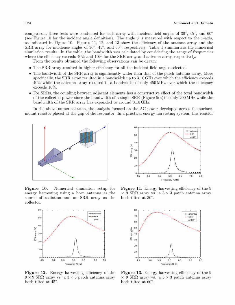
comparison, three tests were conducted for each array with incident field angles of 30◦, 45◦, and 60◦(see Figure 10 for the incident angle definition). The angle φ is measured with respect to the x-axis,as indicated in Figure 10. Figures 11, 12, and 13 show the efficiency of the antenna array and theSRR array for incidence angles of 30◦, 45◦, and 60◦, respectively. Table 1 summarizes the numericalsimulation results. In the table, the bandwidth was calculated by considering the range of frequencieswhere the efficiency exceeds 40% and 10% for the SRR array and antenna array, respectively.
From the results obtained the following observations can be drawn:
• The SRR array resulted in higher efficiency for all the incident field angles selected.• The bandwidth of the SRR array is significantly wider than that of the patch antenna array. More
specifically, the SRR array resulted in a bandwidth up to 3.10 GHz over which the efficiency exceeds40% while the antenna array resulted in a bandwidth of only 450 MHz over which the efficiencyexceeds 10%.
• For SRRs, the coupling between adjacent elements has a constructive effect of the total bandwidthof the collected power since the bandwidth of a single SRR (Figure 5(a)) is only 200 MHz while thebandwidth of the SRR array has expanded to around 3.10 GHz.
In the above numerical tests, the analysis focused on the AC power developed across the surface-mount resistor placed at the gap of the resonator. In a practical energy harvesting system, this resistor
φd
Figure 10. Numerical simulation setup forenergy harvesting using a horn antenna as thesource of radiation and an SRR array as thecollector.
4.5 5.0 5.5 6.0 6.5 7.0 7.50
10
20
30
40
50
60
Effi
cien
cy (
%)
Frequency (GHz)
antenna
SRR
ϕ=30°
Figure 11. Energy harvesting efficiency of the 9× 9 SRR array vs. a 3 × 3 patch antenna arrayboth tilted at 30◦.
4.5 5.0 5.5 6.0 6.5 7.0 7.50
10
20
30
40
50
60
Effi
cien
cy (
%)
Frequency (GHz)
antenna SRR
ϕ=45°
Figure 12. Energy harvesting efficiency of the9 × 9 SRR array vs. a 3 × 3 patch antenna arrayboth tilted at 45◦.
0
10
20
30
40
50
60
70
80
Effi
cien
cy(%
)
Frequency(GHz)
antenna SRR
4.5 5.0 5.5 6.0 6.5 7.0 7.5
ϕ=60°
Figure 13. Energy harvesting efficiency of the 9× 9 SRR array vs. a 3 × 3 patch antenna arrayboth tilted at 60◦.

Progress In Electromagnetics Research B, Vol. 62, 2015 175
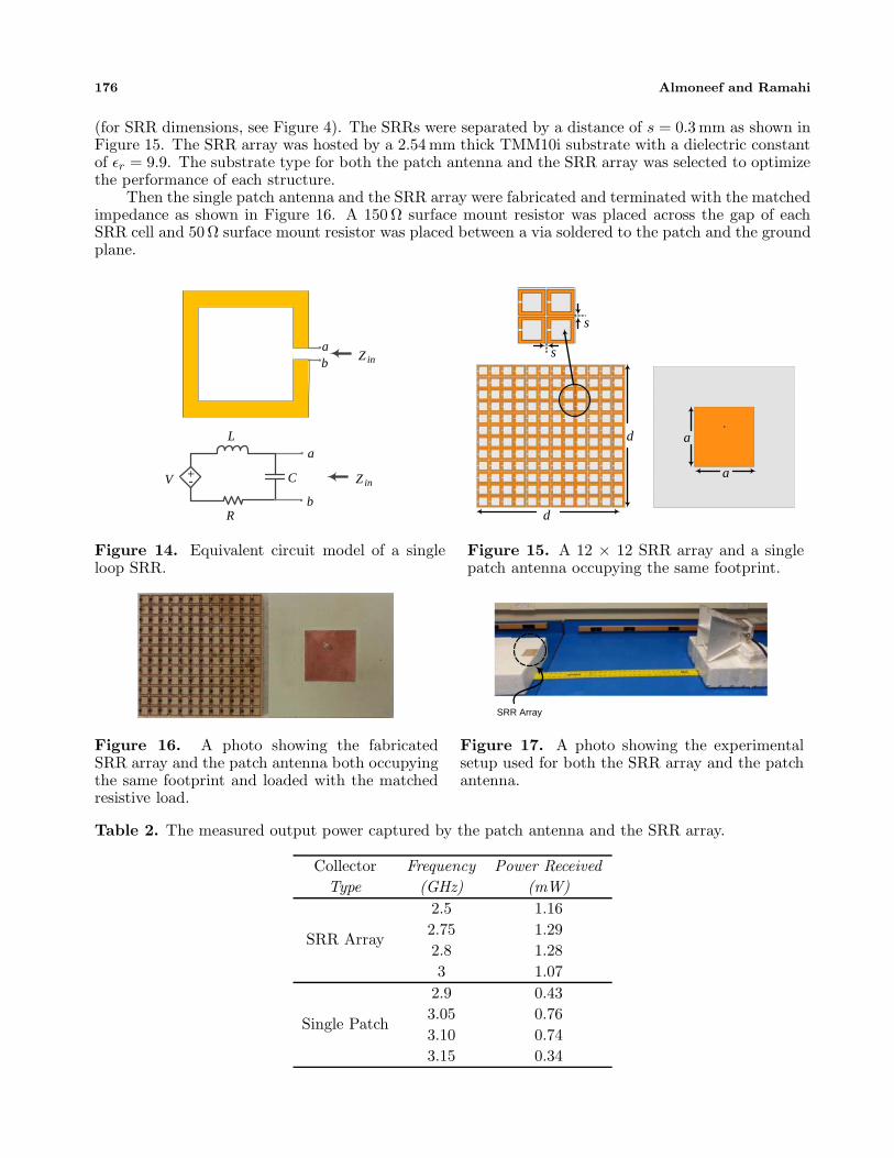
is replaced by a full rectification circuitry that is capable of converting AC power to DC employingmatching networks, diodes such as Schottky diodes and a load. Designing such rectification circuitdepends on the SRR input impedance. The equivalent circuit model of a receiving single loop SRR isshown in Figure 14, where R is the total resistance (radiation and Ohmic), L is the self inductance,and C represents the gap capacitance of the SRR. Here, it is assumed that the resonator is operating atresonance frequency while illuminated by an incident electromagnetic field. Notice that we representedthe voltage induced within the SRR (which is essentially part of the entire emf voltage induced due to thearriving incident wave) as a dependent voltage source. Whether the dependent voltage source is currentdependent or voltage dependent is not of relevance here. What matters is that it is a dependent voltagesource that depends on the magnitude, polarization and frequency of the incident electromagnetic field.
In earlier works using SRR as a building block for metamaterial, the gap provided the capacitanceneeded for resonance. To harvest energy from the SRR through the gap, a resistive load needs to beplaced across the gap. The optimal load resistance at the gap that will maximize power absorptiondepends on the topology of the SRR. Therefore, when designing a loaded SRR to operate at aspecific frequency, the load resistance that can achieve maximum power transfer can be found throughconstrained optimization by varying the resistance and selecting the resistance value that will providemaximum power dissipation across the gap for a particular field polarization and angle of incidence.With reference to Figure 5(b), it is interesting to note that a single square loop with a perimeter of λo/2experiences high resistance at the resonance frequency. This is due to the fact that at this small loopsize, the radiation resistance is much smaller than the case where the perimeter size is slightly largerthan a wavelength [35, 36]. However, when we stack the high resistive loops in a way that each loop isin close proximity to adjacent loops, the input impedance is reduced dramatically to values that allowfor integration of a practical matching networks and other type of associated circuitries. (Interestingly,the change in the internal impedance of the loops was also observed and accounted for in [37]). In thefollowing section, we show that by stacking a 12× 12 SRR loops, one can significantly reduce the inputimpedance of each cell from 14 kΩ (Figure 5(b)) to 150 Ω or other desired value by varying the distanceamong the SRR cells.
5. EXPERIMENTAL VERIFICATION
In this work, the objective is to continue demonstrating the effectiveness of metamaterial arrays forconverting the field energy into available AC power. Experimentally validating the precise structureconsidered above is especially time consuming since the voltage needs to be probed at each SRR gapwhile sweeping over some range of frequencies. Here, we consider a single patch antenna and compareits energy harvesting performance with an array of SRR cells placed on the same footprint of the patchantenna. The patch antenna and the SRR array were redesigned to operate at 3 GHz. (Our choice of3GHz was purely due to the constraints of available test equipment). First a single square patch antennawith a side a = 25.1 mm was designed to resonate at 3 GHz as shown in Figure 15. The patch antennawas placed on top of a grounded RO4350 substrate having a thickness of t = 1.524 mm, a dielectricconstant of εr = 3.66 and a footprint area of 60×60 mm2. Then the same footprint was used to populatean array of 12 × 12 SRRs with each cell having dimensions of l = 4.7 mm, w = 0.6 mm and g = 0.5 mm
Table 1. The performance of the SRR array as compared to the antenna array.
Collector Incident Max Efficency BandwidthType Angle (%) (GHz)
30◦ 53.37 1.40SRR Array 45◦ 51.84 1.65
60◦ 76.31 3.1030◦ 30.56 0.45
Antenna Array 45◦ 25.52 0.2560◦ 23.21 0.20
176 Almoneef and Ramahi
(for SRR dimensions, see Figure 4). The SRRs were separated by a distance of s = 0.3 mm as shown inFigure 15. The SRR array was hosted by a 2.54 mm thick TMM10i substrate with a dielectric constantof εr = 9.9. The substrate type for both the patch antenna and the SRR array was selected to optimizethe performance of each structure.
Then the single patch antenna and the SRR array were fabricated and terminated with the matchedimpedance as shown in Figure 16. A 150 Ω surface mount resistor was placed across the gap of eachSRR cell and 50 Ω surface mount resistor was placed between a via soldered to the patch and the groundplane.
Zinba
b
a
+- Z inC
L
R
V
Figure 14. Equivalent circuit model of a singleloop SRR.
d
d
a
a
s
s
Figure 15. A 12 × 12 SRR array and a singlepatch antenna occupying the same footprint.
Figure 16. A photo showing the fabricatedSRR array and the patch antenna both occupyingthe same footprint and loaded with the matchedresistive load.
SRR Array
Figure 17. A photo showing the experimentalsetup used for both the SRR array and the patchantenna.
Table 2. The measured output power captured by the patch antenna and the SRR array.
Collector Frequency Power ReceivedType (GHz) (mW)
SRR Array
2.5 1.162.75 1.292.8 1.283 1.07
Single Patch
2.9 0.433.05 0.763.10 0.743.15 0.34

Progress In Electromagnetics Research B, Vol. 62, 2015 177
Using a commercially available 12 dB gain horn antenna, an incident field was generated having acenter frequency of 3GHz. Then the fabricated SRR array was placed a distance of 1m away from thehorn antenna to ensure a plane wave excitation as shown in Figure 17. The SRR array was positionedsuch that the H-field is normal to the plane of the array. A 4 GHz Rohde and Schwarz RTO DigitalOscilloscopes equipped with a differential probe was used to record the voltage across each resistiveload. It was found that the SRR array was able to absorber 1.29 mW of the incident field at 2.75 GHzas shown in Table 2. The power collected by the SRR array in Table 2 was calculated by summing themeasured power absorbed across the resistors of all 144 SRR cells at a certain frequency. The slightdeviation of the resonance frequency is attributed to fabrication error. Similarly, the patch antennawas excited with the same setup except that the patch antenna was positioned so that the E-field isparallel to the patch surface. It was found that the patch was capable of capturing a maximum powerof 0.76 mW as indicated by Table 2. The type of field excitation was chosen such that both structuresexperience maximum incident field absorption. It is evident from the experimental results that the SRRis capable of absorbing more power per footprint when comparison to the patch antenna. In fact, theresults show 70% improvement of the harvested power when using SRRs.
6. DISCUSSION
Since the emergence of metamaterials and until very recently when the potential of harvestingelectromagnetic energy using metamaterial particles was first introduced [17], metamaterial has neverbeen analyzed for the reception of electromagnetic energy. In order to understand the feasibility ofa single metamaterial cell, especially the SRR, to receive energy in the far field, similar to classicalantennas, we revisited the concept of reciprocity.
Reciprocity states that for any two radiating elements in a certain medium, if a 1 Amp currentsource is placed across the feed nodes of either radiators and the voltage is recorded across the opencircuit feed of the other radiator, then exchanging the current source and voltmeter produces the samereading (see for example the discussion in [35]). A very simple numerical experiment is conducted toshow that even though the SRR is an electrically small resonator, it indeed follows the rules of reciprocityand can therefore receive energy. To this end, we consider a dipole antenna and a single loop SRR,both resonating at the same frequency. The experiment is divided into four cases: for the first case,an SRR is excited by a current source placed across its gap and then the voltage across the feed of thedipole antenna is recorded. In the second case, a dipole antenna is excited by a current source placedat its feed, then the voltage across the gap of the SRR is recorded as shown in Figures 18(a) and (b).The voltage of both cases can be found as V = E · d where E is the electric field at the feed and d isthe gap length vector of the feed of each radiator. Simulation results give identical voltage readings for
(a) Case 1 (b) Case 2
v
v
(c) Case 3 (d) Case 4
vac
v
vvac
Voltmeter
Voltmeter
VoltageSource
Voltmeter
Current Source
VoltageSource
Voltmeter
Current Source
Figure 18. Simulation setup illustrating the reciprocity theorem for (a) case 1, (b) case 2, (c) case 3,and (d) case 4, as described in the Section 6. In each case, the relative size of the two radiators is notto scale.

178 Almoneef and Ramahi
both cases. When a voltage source was used instead of a current source, as in Figures 18(c) and (d),different readings were obtained for the feed voltages.
These results confirm that despite reciprocity, the potential for an antenna to be an efficienttransmitter does not equate to its potential to be an efficient receiver. This very simple numericalexercise shows conclusively that while the SRRs might not be a suitable choice to operate as atransmitting antenna due to practical source considerations, they indeed can operate as a receiverwhose effectiveness can be varied due to additional factors such as impedance matching and proximityto adjacent cells.
7. CONCLUSION
The feasibility of using SRRs to harvest microwave energy was studied through simulation by firstplacing a resistive load across the gap of a single loop SRR then calculating the power dissipated acrossthe resistor. An experiment was then conducted to test the feasibility of SRRs to harvest microwaveenergy. The fabricated SRR cell was excited by an antenna placed 30 cm away, and then the voltageacross the gap was measured using a high-frequency oscilloscope. A voltage of 611 mV was observedacross the gap when 24 dBm power level was pumped into the transmitting antenna feed.
The efficiency of an array of SRRs was compared to that of an array of antennas occupying thesame footprint. The numerical simulation results show that the SRR array is capable of electromagneticenergy harvesting efficiency of 40% or higher over a bandwidth of 3.10 GHz while the patch antennaarray gave an efficiency of 10% or higher over a bandwidth of only 450 MHz. While we providedcomparison to an array of patch microstrip antennas, other types of patch antennas could providelower or possibly higher efficiency than the microstrip antenna array used here. It is evident fromthe numerical simulations presented that the SRR array provides significantly higher power harvestingefficiency and more critically wider bandwidth as compared to the antenna array. As a proof of concept,a single patch antenna and a 12 × 12 SRR array were compared in terms of maximum power outputcaptured by each structure. It was found that the SRR array provided 60% more power per footprintthan the patch antenna which verify the results obtained through numerical simulation. These resultsare expected to have strong impact on the viability and efficiency of electromagnetic energy harvestingin general.
ACKNOWLEDGMENT
The authors like to acknowledge the support of the Natural Sciences and Engineering Research Council,Canada and the Saudi Arabian Ministry of Higher Education. We also would like to acknowledge CMCMicrosystems for the provision of products and services that facilitated this research, including CADtools and test support.
REFERENCES
1. Brown, W. C., “The history of power transmission by radio waves,” IEEE Transactions onMicrowave Theory and Techniques, Vol. 32, No. 9, 1230–1242, 1984.
2. Curty, J., M. Declercq, C. Dehollain, and N. Joehl, Design and Optimization of Passive UHF RFIDSystems, Springer Publishing Company, Incorporated, 2010.
3. Yagi, H. and S. Uda, “On the feasibility of power transmission by electric waves,” Proceedings ofthe Third Pan-Pacific Science Congress, Vol. 2, 1305–1313, 1926.
4. “Electric light without current,” Literary Digest, Vol. 112, 30, 1932.5. Strassner, II, B. and K. Chang, “Rectifying antennas (rectennas),” Encyclopedia of RF and
Microwave Engineering, 2005.6. Erb, R., “Power from space — The tough questions: The 1995 Peter E. Glaser lecture,” Acta
Astronautica, Vol. 38, No. 48, 539–550, 1996, Benets of Space for Humanity, Online Available:http://www.sciencedirect.com/science/article/pii/0094576596823241.

Progress In Electromagnetics Research B, Vol. 62, 2015 179
7. Glaser, P. E., “An overview of the solar power satellite option,” IEEE Transactions on MicrowaveTheory and Techniques, Vol. 40, No. 6, 1230–1238, 1992.
8. Brown, W., “Electronic and mechanical improvement of the receiving terminal of a free-spacemicrowave power transmission system,” NASA STI/Recon Technical Report N, Vol. 77, 31613,1977.
9. McSpadden, J., “Rectifying and oscillating integrated antennas,” Ph.D. Dissertation, Texas A&MUniversity, 1998.
10. Brown, W. and J. Triner, “Experimental thin-film, etched-circuit rectenna,” 1982 IEEE MTT-SInternational Microwave Symposium Digest, 185–187, 1982.
11. Koert, P., J. Cha, and M. Machina, “35 and 94 GHz rectifying antenna systems,” SPS 91 — Powerfrom Space, Vol. 1, 541–547, 1991.
12. Bharj, S., R. Camisa, S. Grober, F. Wozniak, and E. Pendleton, “High efficiency C-band 1000element rectenna array for microwave powered applications,” 1992 IEEE MTT-S InternationalMicrowave Symposium Digest, 301–303, 1992.
13. Ren, Y. and K. Chang, “5.8-GHz circularly polarized dual-diode rectenna and rectenna array formicrowave power transmission,” IEEE Transactions on Microwave Theory and Techniques, Vol. 54,No. 4, 1495–1502, 2006.
14. Harouni, Z., L. Cirio, L. Osman, A. Gharsallah, and O. Picon, “A dual circularly polarized2.45 GHz rectenna for wireless power transmission,” IEEE Antennas and Wireless PropagationLetters, Vol. 10, 306–309, 2011.
15. Hagerty, J. and Z. Popovic, “An experimental and theoretical characterization of a broadbandarbitrarily-polarized rectenna array,” 2001 IEEE MTT-S International Microwave SymposiumDigest, Vol. 3, 1855–1858, 2001.
16. Hagerty, J., F. Helmbrecht, W. McCalpin, R. Zane, and Z. Popovic, “Recycling ambientmicrowave energy with broad-band rectenna arrays,” IEEE Transactions on Microwave Theoryand Techniques, Vol. 52, No. 3, 1014–1024, 2004.
17. Ramahi, O., T. Almoneef, M. Alshareef, and M. Boybay, “Metamaterial particles forelectromagnetic energy harvesting,” Applied Physics Letters, Vol. 101, No. 17, 173903, 2012.
18. Yoo, T. and K. Chang, “Theoretical and experimental development of 10 and 35 GHz rectennas,”IEEE Transactions on Microwave Theory and Techniques, Vol. 40, No. 6, 1259–1266, 1992.
19. McSpadden, J., L. Fan, and K. Chang, “A high conversion efficiency 5.8 GHz rectenna,” 1997 IEEEMTT-S International Microwave Symposium Digest, Vol. 2, 547–550, 1997.
20. Chin, C., Q. Xue, and C. Chan, “Design of a 5.8-GHz rectenna incorporating a new patch antenna,”IEEE Antennas and Wireless Propagation Letters, Vol. 4, 175–178, 2005.
21. Strassner, B. and K. Chang, “5.8-GHz circularly polarized rectifying antenna for wireless microwavepower transmission,” IEEE Transactions on Microwave Theory and Techniques, Vol. 50, No. 8,1870–1876, 2002.
22. Monti, G., L. Tarricone, and M. Spartano, “X-band planar rectenna,” IEEE Antennas and WirelessPropagation Letters, Vol. 10, 1116–1119, 2011.
23. Hawkes, A. M., A. R. Katko, and S. A. Cummer, “A microwave metamaterial with integratedpower harvesting functionality,” Applied Physics Letters, Vol. 103, No. 16, 2013, Online Available:http://scitation.aip.org/content/aip/journal/apl/103/16/10.1063/1.4824473.
24. Almoneef, T. and O. M. Ramahi, “A 3-dimensional stacked metamaterial arrays for electromagneticenergy harvesting,” Progress In Electromagnetics Research, Vol. 146, 109–115, 2014.
25. Yo, T., C. Lee, C. Hsu, and C. Luo, “Compact circularly polarized rectenna with unbalancedcircular slots,” IEEE Transactions on Antennas and Propagation, Vol. 56, No. 3, 882–886, 2008.
26. Heikkinen, J. and M. Kivikoski, “A novel dual-frequency circularly polarized rectenna,” IEEEAntennas and Wireless Propagation Letters, Vol. 2, 330–333, 2003.
27. Solymar, L. and E. Shamonina, Waves in Metamaterials, Oxford University Press, USA, 2009.28. Mei, Z., J. Bai, T. Niu, and T. Cui, “A half Maxwell fish-eye lens antenna based on gradient-index
metamaterials,” IEEE Transactions on Antennas and Propagation, Vol. 60, No. 1, 398–401, 2012.

180 Almoneef and Ramahi
29. Khan, M. and M. Mughal, “Design of tunable metamaterials by varying the height of rings of S-shaped resonator,” IEEE Third International Conference on Electrical Engineering, ICEE’09, 1–4,2009.
30. Aydin, K., I. Bulu, K. Guven, M. Kafesaki, C. Soukoulis, and E. Ozbay, “Investigation of magneticresonances for different split-ring resonator parameters and designs,” New Journal of Physics,Vol. 7, 168, 2005.
31. Bilotti, F., A. Toscano, L. Vegni, K. Aydin, K. Alici, and E. Ozbay, “Equivalent-circuit modelsfor the design of metamaterials based on artificial magnetic inclusions,” IEEE Transactions onMicrowave Theory and Techniques, Vol. 55, No. 12, 2865–2873, 2007.
32. AlShareef, M. R. and O. M. Ramahi, “Electrically small resonators for energy harvesting inthe infrared regime,” Journal of Applied Physics, Vol. 114, No. 22, 2013, Online Available:http://scitation.aip.org/content/aip/journal/jap/114/22/10.1063/1.4846076.
33. Stutzman, W. L. and G. Thiele, Antenna Theory and Design, John Wiley, New York, 1981.34. Lau, B. K. and Z. Ying, “Antenna design challenges and solutions for compact MIMO terminals,”
2011 International Workshop on Antenna Technology (iWAT), 70–73, 2011.35. Balanis, C. A., Antenna Theory: Analysis and Design, John Wiley & Sons, 2012.36. Storer, J. E., “Impedance of thin-wire loop antennas,” Transactions of the American Institute of
Electrical Engineers, Part I: Communication and Electronics, Vol. 75, No. 5, 606–619, Nov. 1956.37. Gorkunov, M., M. Lapine, E. Shamonina, and K. H. Ringhofer, “Effective magnetic properties of
a composite material with circular conductive elements,” Eur. Phys. J. B, Vol. 28, 263–269, 2002.