"spin currents in noncollinear magnetic structures: when linear response goes beyond...
Post on 20-Dec-2015
220 views
TRANSCRIPT
"Spin currents in noncollinear magnetic
structures: when linear response goes beyond equilibrium
states"

Nanopillar Structure
F
F
Au
Cu
CuP
AP
I
I
V
V
F = Co, PyH
Dimensions ~ 60 nm x 130 nm
The inverse of GMR-Current Induced Magnetic Switching

SAMPLES
MSU Nanopillars
tCu
Py or Co
CuI
Au
I
Py or Co2.5 – 6 nm
30 nm
~130 nm
~70nm
Uncoupled F layers: tCu = 10nm
Ferromagnetically-coupledF layers: tCu = 2.6 nm
H
Antiferromagnetically-coupledF layers: tCu = 10 nm
Cu
Au
Py or Co
Py or Co
H

-6 -4 -2 0 2 4 61.50
1.52
1.54
1.56
-1.0 -0.5 0.0 0.5 1.0
1.50
1.52
1.54
1.56
dV/dI (Ohm)
I (mA)
dV/dI (Ohm)
H (kOe)
Uncoupled Co/Cu/Co Nanopillar: l1 ~ 130 nm; l2 ~ 70 nm.
H = 0
MR 5%
R(I)
P P
AP AP
AP
P
I = 0
AP
P
Is
295K
Hysteretic

How can one rotate a magnetic layer with a spin polarized current?By spin torques:Slonczewski-1996Berger -1996Waintal et al-2000Brataas et al-2000Stiles et al-2002
By current induced interlayer coupling:Heide- 2001
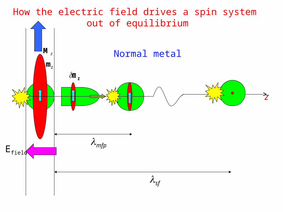
Mz
Efield
z
How the electric field drives a spin system out of equilibrium
δmz
λmfp
λsf
mz
Normal metal

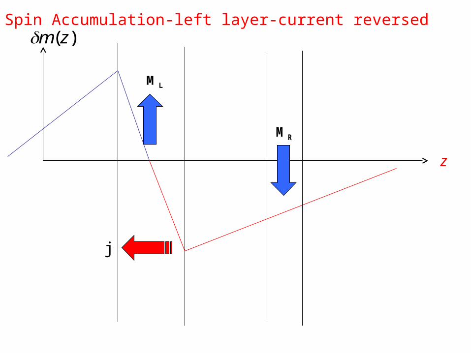
)(zmδ
ML
MR
j
z
Spin Accumulation from left layer
ML
MR
j
z
Spin Accumulation-left layer-current reversed)(zmδ
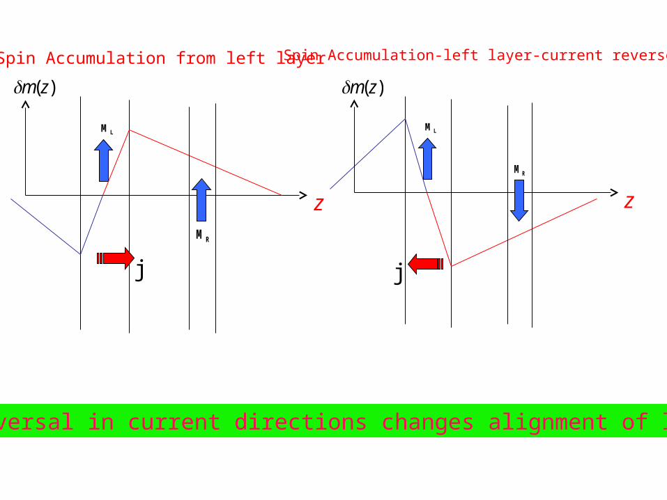
δm(z)
ML
MR
j
z
Spin Accumulation from left layer
δm(z)
ML
MR
j
z
Spin Accumulation-left layer-current reversed
How reversal in current directions changes alignment of layers
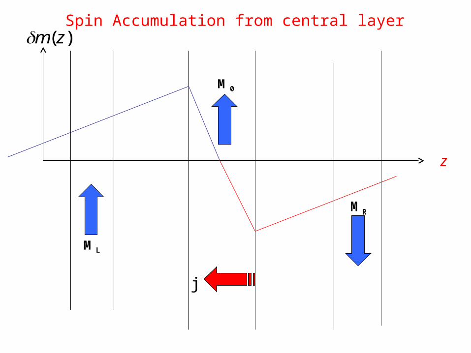
M0
MR
j
z
ML
Spin Accumulation from central layer)(zmδ
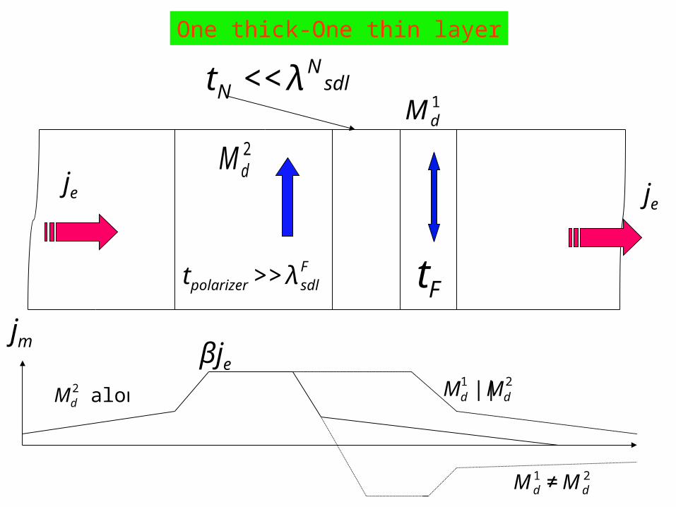
1dM
2dM
Ft
tN <<λNsdl
One thick-One thin layer
jeje
tpolarizer>>λsdlF
jmβje
€
M d1 ≠M d
2
Md2 alone Md
1 ||Md2

ˆ C =e2 ˆ N (εF)ˆ D
ˆ C =C0ˆ I +σ ⋅C, D =D0
ˆ I +σ ⋅D,
ˆ n =n0ˆ I +σ ⋅m
C=βC0Md, D= ′ β D0Md
j (x)=ˆ C E(x)−ˆ D ∂ˆ n ∂x
First attempt: Spin diffusion equation
Spinor current

jm =βjeMd −2D0
∂m∂x
−β ′ β Md(Md ⋅∂m∂x
)⎡ ⎣ ⎢
⎤ ⎦ ⎥
Part due to band structure
Contribution from diffusive processes
Accumulation of spin near interfaces alters equilibrium densities
Asya Shpiro et al. Phys. Rev.B67,104430 (2003).

∂2m||
∂x2 −m||
λ2sdl
=0
λsdl = 1−β ′ β λsf
Stationary solutions for spin accumulation
Longitudinal
Transverse
€
∂2m⊥
∂x 2−
m⊥
λ2sf
−m⊥× Md
λ J2
= 0
λ J =dJλ mfp
3π dJ = hvF J
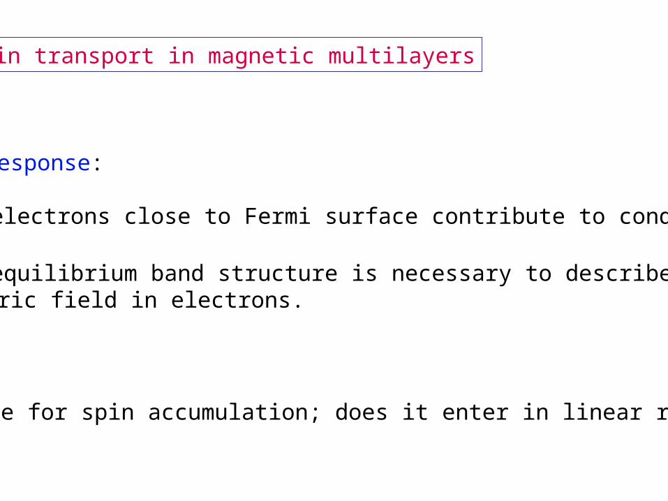
Spin transport in magnetic multilayers
Linear response:
• only electrons close to Fermi surface contribute to conduction
• only equilibrium band structure is necessary to describe effectof electric field in electrons.
The case for spin accumulation; does it enter in linear response?

•Due to screening in metals transport in each layer can be modeled by equilibrium band structure.•Solve for distribution function ( statistical density matrix) in each layer by using the Boltzmann equation.•The distribution functions describing the out of equilibrium transport across layers are connected by the scattering matrices at the interfaces.
Layer by layer approach to transport in metallic structures:

Conclusion:
Attendant to current driven across inhomogeneous media there ischarge and spin redistribution so as to maintain a steady state current.
As seen from the Boltzmann equation this out of equilibrium accumulation enters in linear response.
In the Kubo approach it alters the local electric field seen by the electrons from that externally applied. For magnetic media the effective field for spin channels are different.
This has been sufficient to describe transport in collinear magneticstructures, but it is in sufficient when the magnetic layers are noncollinear?

Spin transport in noncollinear magnetic multilayers
Does one have to alter the layer by layer approach to transport in metallic structures that has worked so well for collinear magnetic multilayers?
Yes
How

Current induced coherences
Spin distributions transverse to the magnetization are described bycorrelations between up and down spin states.
In the one electron spin polarized picture of ferromagnetic band structure there are no correlations between spin split bands inequilibrium.
For these correlations to exist they must be induced by the current.
They can only be induced by the spin-flip scattering at the interfaces. This only happens if the symmetry is lowered by the presence ofspin polarized currents.
For the same reason that spin accumulation enters in linear responsethe effect of this current induced coherence also enters linearly.
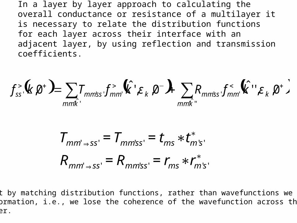
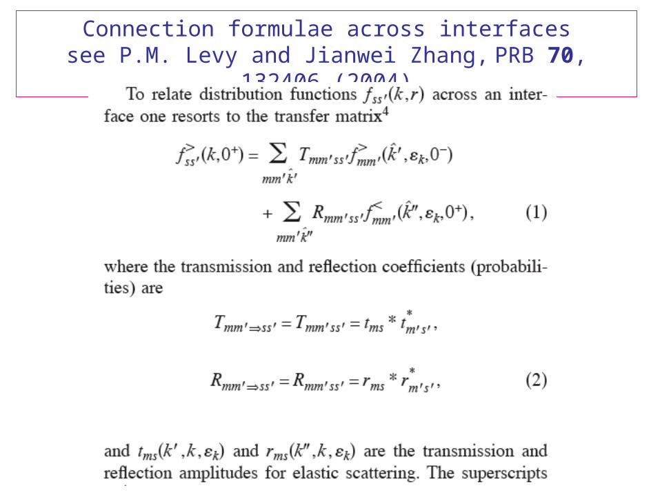
In a layer by layer approach to calculating the overall conductance or resistance of a multilayer it is necessary to relate the distribution functions for each layer across their interface with an adjacent layer, by using reflection and transmission coefficients.
( ) ( ) ( )+<−>+> ∑∑ += 0,,''ˆ0,,'ˆ0,''ˆ'
''''ˆ'
'''' kkmm
mmssmmkkmm
mmssmmss kfRkfTkf εε
€
Tmm'⇒ ss' = Tmm'ss' = tms∗tm 's'∗
Rmm'⇒ ss' = Rmm'ss' = rms∗rm's'∗
Note that by matching distribution functions, rather than wavefunctions we losesome information, i.e., we lose the coherence of the wavefunction across the multilayer.

If the distance between ferromagnetic layers exceeds the interlayer coupling distance due to the equilibrium RKKY-like coupling then there is a unique direction for the magnetization at each N/F interface for the system in equilibrium. This dictates that in equilibrium the scattering amplitudes are diagonal in spin space when referred to this unique axis, and that the transmission and reflection coefficients can only transmit the component of an incoming spin current that is parallel to the magnetization of the ferromagnetic layer, i.e, there is no transmission of transverse spin currents.
However, when a current flows across a magnetic multilayer the spin accumulation created at one N/F interface is superimposed on other N/F interfaces that are within a spin diffusion length of it. When the layers are noncollinear the symmetry at the N/F interfaces is lowered so that scattering amplitudes contain off diagonal components in spin space, and transverse components of the spin current are transmitted.

Steady state calculationLocal axis coordinates

Methodology: Boltzmann equation usingthe layer-by-layer approach
Boltzmann equation for spin currents in ferromagnetic metals.See Jianwei Zhang et al., PRL 93, 256602 (2004).


Equations of motion for distribution
functions
sf
pp
p
pp
Fppxxppt
ffffveEfvf
ττεεδ ')(
−−
−−=−−∂+∂
p
pp
pp
pxxppt
fff
Jifvf
τ
±±±±±
−−=∂+∂
hm
Longitudinal
Transverse
Transient response is crucial to understanding states off the Fermisurface contribute to conduction in linear response.

Band structure of Co

Parallel to magnetization Due to accumulation
Charge current
Spin current
Circuit theory
Circuit theory

Definition of transverse spin current, in the steady state

•In a statistical density matrix, e.g., the Boltzmann distribution function, there are diagonal matrix elements which representpopulations, and the off diagonal which are coherencesbetween states.
•For noncollinear multilayers one must be mindful of coherences.
•In equilibrium magnetic layers are not magnetically coupled;in the presence of a spin current across a normal spacer the scattering at the opposite interfaces of the spacer interactwith one another, e.g., see Valet and Fert PRB 48, 7099 (93).
•CISP’s is our way of introducing in a steady state calculationtransients that admix excited k states into the ground stateso as to arrive at the correct steady state.

Solution for multilayer is to find distribution function in each layer by using Boltzmann equation. To determineunknown constants one has to match functions across layers by using the transmission and reflection coefficients.
For example, for transverse distribution function
Connection formulae across interfacessee P.M. Levy and Jianwei Zhang, PRB 70, 132406 (2004)

This leads to the “mixing conductance in the conventional view.


A is the new current induced spin-flip term


Interference pattern- y polarization

Interference pattern - x polarization

No spin-flip at interfaces

Spin currents
-20 -15 -10 -5 0 5 10 15 20-0.1
0.0
0.1
0.2
0.3
0.4
0.5
0.6
0.7
0.8
X (nm)
|j+|(x)
jz(x)
Spin Currents
θ=900 =0.05 A
-20 -15 -10 -5 0 5 10 15 20-0.1
0.0
0.1
0.2
0.3
0.4
0.5
0.6
0.7
0.8
X (nm)
Spin Currents
θ=900 =0.5 A
|j+|( ) x j
z( ) x
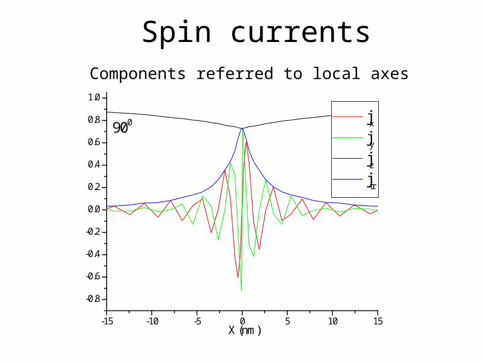
Spin currents
-15 -10 -5 0 5 10 15
-0.8
-0.6
-0.4
-0.2
0.0
0.2
0.4
0.6
0.8
1.0
X (nm)
jx
jy
jz
jtr
spin currents
900
Components referred to local axes
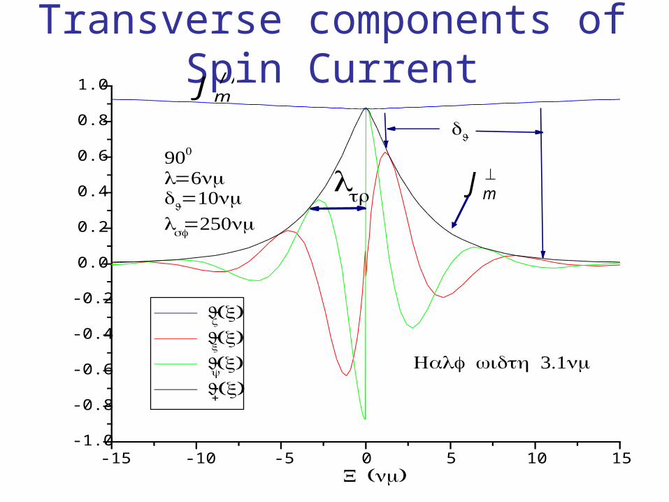
Transverse components of Spin Current//mJ
⊥mJ
-15 -10 -5 0 5 10 15-1.0
-0.8
-0.6
-0.4
-0.2
0.0
0.2
0.4
0.6
0.8
1.0
λtr
dJ
Spin Current J
m
( )X nm
900 λ=6nmd
J=10nm
λsf=250nm
Jz( )x
Jx( )x
Jy( )x
J+( )x 3.1Half width nm

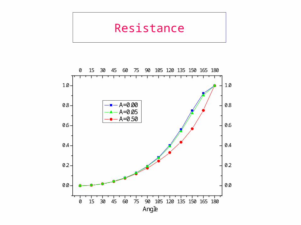
Resistance
0 15 30 45 60 75 90 105 120 135 150 165 180
0 15 30 45 60 75 90 105 120 135 150 165 180
0.0
0.2
0.4
0.6
0.8
1.0
0.0
0.2
0.4
0.6
0.8
1.0
Resistance
Angle
A=0.00 A=0.05 A=0.50


Spin torque as a function of angle between layers for three different cases
of current induced spin flip (CISP)
0 30 60 90 120 150 1800.0
0.1
0.2
0.3
0.4
0.5
0.6
A=0.5 A=0.05 A=0
Torque
Angle

Consequences
• Resistance is lower when one admits transverse currents in ferromagnetic layers.
•Angular variation of resistance and spin torque is changed upon including current induced spin flip, CISP, at interfaces.
•Spin torque is increased for same amount of energy expended when one includes CISP.
•True “mixing” conductance with an effective field component, as well as torque.
•Spatial variation of spin torque and effective field very different.
•Observation: Transmission from Cu to Co favors majoritychannel; penalizes minority channel conduction.

Time dependence of spin transport

Solution is found across entire multilayer by using source terms at interfaces. This obviates any assumptions about the scattering at interfaces; they are built into the Hamiltonian.

The magnetization current normalized to (μB /e)PJ e as a function of position
at times t =0.2τsf,τsf, and 5τsf.
From: S. Zhang and P.M. Levy, Phys. Rev. B65, 052409 (2002).
€
−βje
€
βje
Spin currents

Time evolution of spin current for layers 900 apart Components referred
to global axes

Time evolution of spin current for layers 900 apart Components referred
to global axes

Time evolution of spin current for layers 900 apart Components referred
to global axes

Discontinuity in inhomogeneous solution

Spin currents at steady state

Spin accumulations at steady state

Time dependence of spin torque

Initial Build Up

Spatial Variation

Dependence on mfpλ
0 5 10 15 20 25 30 35 40 45 500
1
2
3
4
5
6
7
8
9
10
λtr( )nm
λBoltz
for dJ=12nm
λJ for d
J=12nm
λJ for d
J=6.28nm
λBoltz
for dJ=6.28nm
λJ for d
J=1nm
λBoltz
for dJ=1nm
λmfp ( )nm
DiffJ
mfpJJ
FJ
d
J
vhd
λλπλ
λ
=
=
=
3
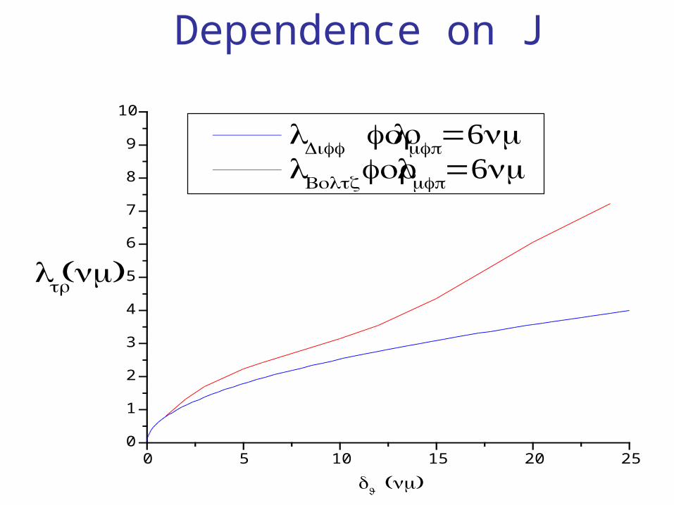
Dependence on J
0 5 10 15 20 250
1
2
3
4
5
6
7
8
9
10
λtr( )nm
λDiff forλ
mfp=6nm
λBoltz
forλmfp=6nm
dJ ( )nm
Why ab-initio have not found the transverse length scalewe find.
They have used the Landauer-Keldysh formalism and arecapable of finding spin accumulation; both longitudinal aswell as transverse.
However, to date their calculations have been done only forthe steady state. The new feature of transport in noncollinearstructures is that it is necessary to calculate a transient phaseduring which states of opposite spin, off the Fermi surface,are mixed into those on the Fermi surface.
Quite aside from the origin of the current induced spin flip scattering we conclude by presenting its effect on the spin transport in noncollinear magnetic multilayers.• Its very existence assures the continuity of the spin current across the N/F interfaces.• The amount of spin accumulation transverse to the magnetization is proportional to this current induced spin flip scattering.• The length scale for the transverse accumulation does not depend onthe current induced spin flip scattering; rather it is set by the exchange parameter J entering equation of motion for the transverse distribution function.• For a given potential drop the charge current is always larger when this spin-flip scattering is present at the interface,i.e., the resistance is always lower.
• The angular dependence of the resistance, and therefore the spin torque, depends on the amount of this current induced spin flip scattering.

Conclusions
In the conventional approach there is a discontinuity in the spin current at the N/F interfaces, while in our approach there is none.
Therefore the origin of the discontinuity cannot be the band mismatch per se; rather the key difference is that we account for the coherence between states of opposite spin in the ferromagnetic layers that is lost in effective single electron treatments.There is a problem with the layer-by-layer approach to calculating
transport in noncollinear magnetic structures; among other things it overlooks the fact that for these structure there are no pure spin states