spi hs 30 overview - banner-ever.com test/parmi/spi hs60 overview... · overview feb. 2009 spi hs60...
TRANSCRIPT

OVERVIEW
Feb. 2009
SPI HS60 series
INTRODUCTION
SPI HS60 System
The major roles of the system
Customer’s benefits
- 3 -
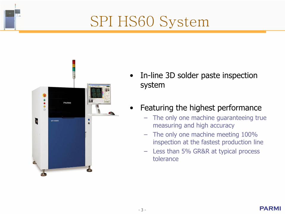
SPI HS60 System
• In-line 3D solder paste inspection system
• Featuring the highest performance – The only one machine guaranteeing true
measuring and high accuracy
– The only one machine meeting 100% inspection at the fastest production line
– Less than 5% GR&R at typical process tolerance

- 4 -
The major roles of the system
Detecting faulty solder paste locations with “zero” false calls- Volume, Height, Area, Positional Offset, Bridge, Shape
SPC (Statistical process control)- Classical printing process monitoring & control functions- Anyone can have network connection to a machine DB for SPC- Real time monitoring & analysis
Monitoring the current printing process- Helps operator to know printing status quickly at production lines

- 5 -
Customer’s benefits
Due to high FPY rateCut down rework costs (save
components & PCBs)
Prevent faulty PCBs from going through next process
Helps operator do proper actions on the screen printer
Get optimal control of printing process
Prevent outdoor failure
HARDWARE
Outlook and Dimension
Hardware Schematics
Hardware Configuration
X-Y Gantry Robot
Conveyor Stage
Electric Assemblies
- 7 -
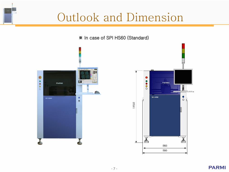
Outlook and Dimension
※ In case of SPI HS60 (Standard)
- 8 -
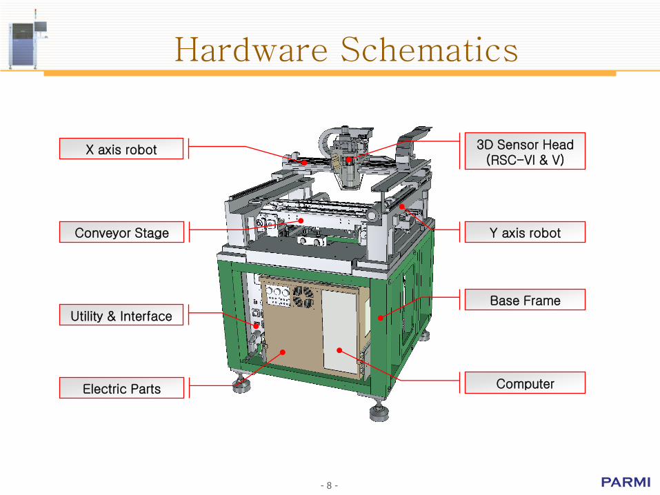
Hardware Schematics
Base Frame
3D Sensor Head(RSC-VI & V)
X axis robot
Electric Parts
Conveyor Stage Y axis robot
Computer
Utility & Interface

- 9 -
• Gantry X-Y robot - Small foot print
- Linear motor driven X stage
Hardware Configuration
• Conveyor stage- Auto width adjustment
- Clamping mechanism with backup pins
• 3D sensor with Z axis stage- Obtain 2D & 3D image
- 10 -
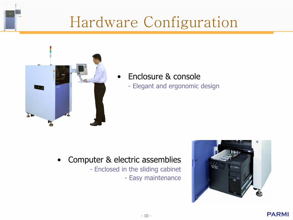
• Enclosure & console- Elegant and ergonomic design
Hardware Configuration
• Computer & electric assemblies- Enclosed in the sliding cabinet
- Easy maintenance
- 11 -
X-Y Gantry Robot
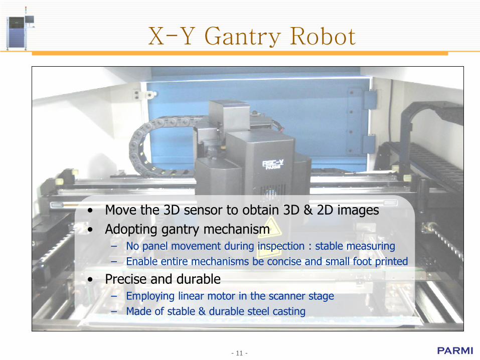
• Move the 3D sensor to obtain 3D & 2D images
• Adopting gantry mechanism– No panel movement during inspection : stable measuring
– Enable entire mechanisms be concise and small foot printed
• Precise and durable– Employing linear motor in the scanner stage
– Made of stable & durable steel casting
- 12 -
X-Y Gantry Robot
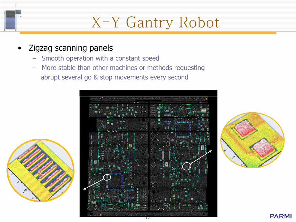
• Zigzag scanning panels– Smooth operation with a constant speed
– More stable than other machines or methods requesting
abrupt several go & stop movements every second
- 13 -
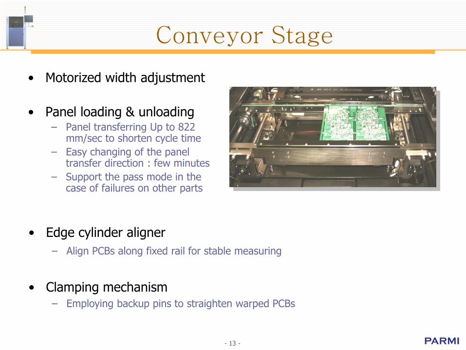
Conveyor Stage
• Motorized width adjustment
• Panel loading & unloading– Panel transferring Up to 822
mm/sec to shorten cycle time
– Easy changing of the panel transfer direction : few minutes
– Support the pass mode in the case of failures on other parts
• Edge cylinder aligner
– Align PCBs along fixed rail for stable measuring
• Clamping mechanism– Employing backup pins to straighten warped PCBs
- 14 -
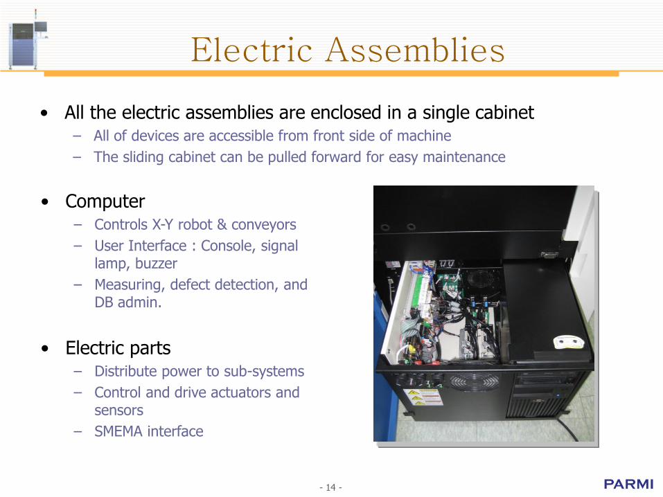
• All the electric assemblies are enclosed in a single cabinet– All of devices are accessible from front side of machine
– The sliding cabinet can be pulled forward for easy maintenance
Electric Assemblies
• Computer– Controls X-Y robot & conveyors
– User Interface : Console, signal lamp, buzzer
– Measuring, defect detection, and DB admin.
• Electric parts– Distribute power to sub-systems
– Control and drive actuators and sensors
– SMEMA interface

3D SENSOR
RSC V
Outstanding Performance
3D Images of Components
3D Images of Panels
- 16 -
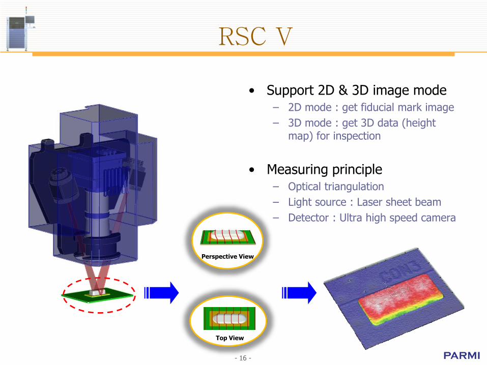
RSC V
• Support 2D & 3D image mode– 2D mode : get fiducial mark image
– 3D mode : get 3D data (height map) for inspection
• Measuring principle– Optical triangulation
– Light source : Laser sheet beam
– Detector : Ultra high speed camera
Perspective View
Top View
- 17 -
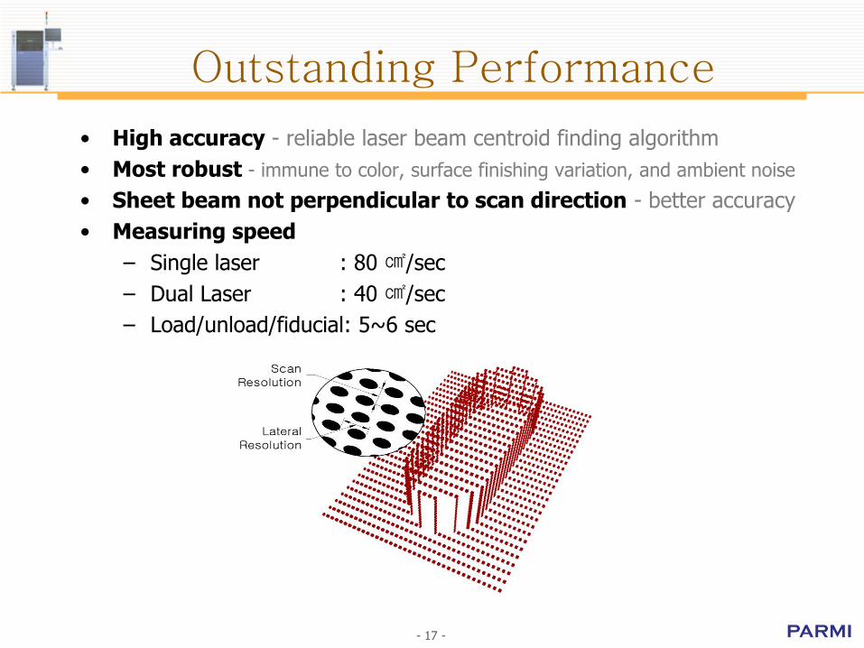
Outstanding Performance
• High accuracy - reliable laser beam centroid finding algorithm
• Most robust - immune to color, surface finishing variation, and ambient noise
• Sheet beam not perpendicular to scan direction - better accuracy
• Measuring speed
– Single laser : 80 ㎠/sec
– Dual Laser : 40 ㎠/sec
– Load/unload/fiducial: 5~6 sec
- 18 -
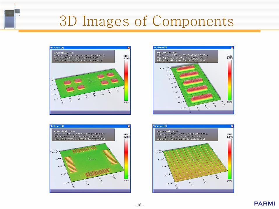
3D Images of Components
BGA site QFP site
- 19 -
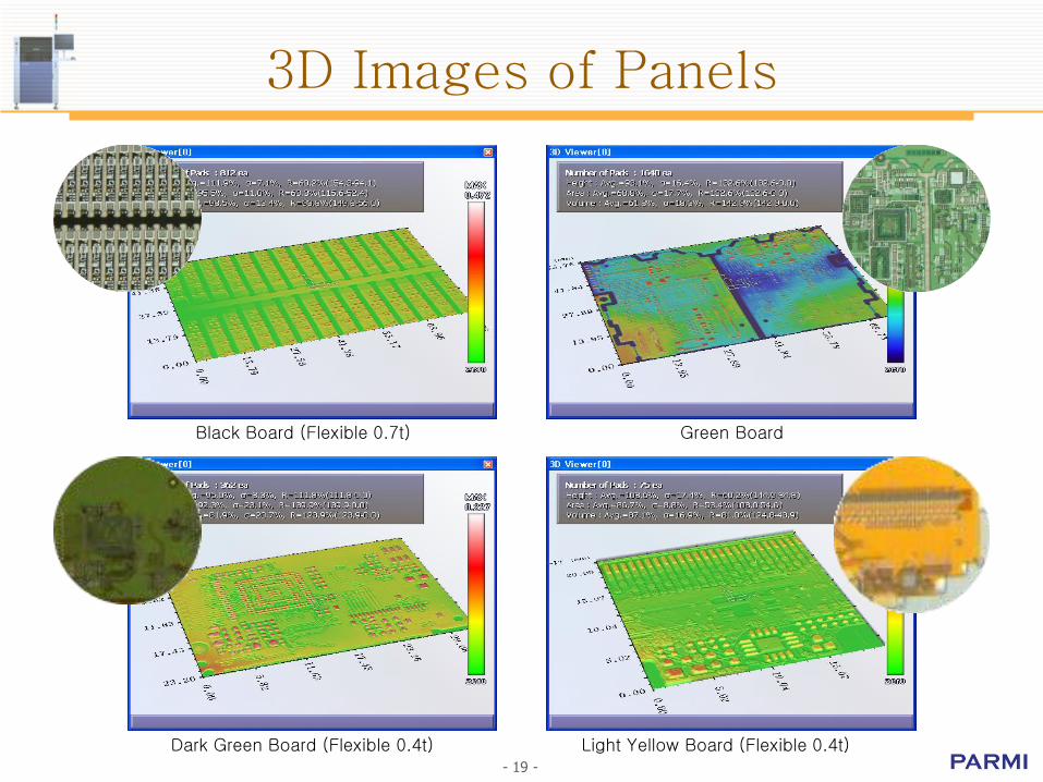
3D Images of Panels
Green BoardBlack Board (Flexible 0.7t)
Light Yellow Board (Flexible 0.4t)Dark Green Board (Flexible 0.4t)
Operation Software
Software for panel inspection
Summary of SPIworks
Summary of ePm-SPI
Summary of SPCworks

- 21 -
Software for panel inspection
SPIworksInspection program
SPCworksSPC program
ePm-SPITeaching program
- 22 -
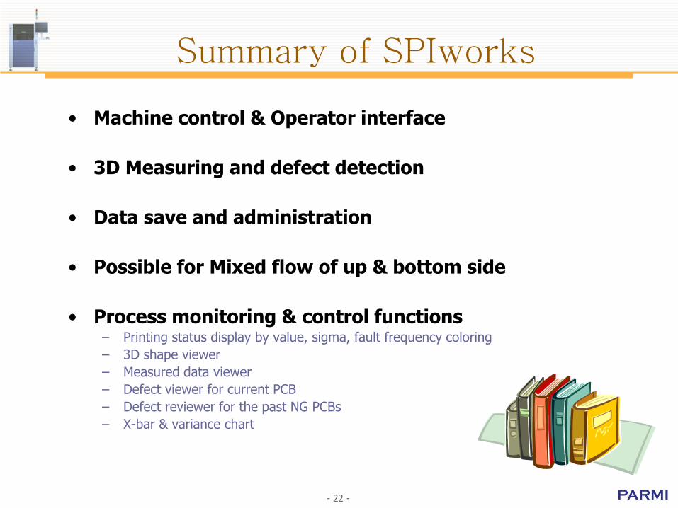
Summary of SPIworks
• Machine control & Operator interface
• 3D Measuring and defect detection
• Data save and administration
• Possible for Mixed flow of up & bottom side
• Process monitoring & control functions– Printing status display by value, sigma, fault frequency coloring
– 3D shape viewer
– Measured data viewer
– Defect viewer for current PCB
– Defect reviewer for the past NG PCBs
– X-bar & variance chart
- 23 -
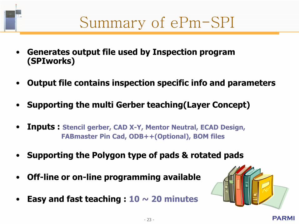
• Generates output file used by Inspection program (SPIworks)
• Output file contains inspection specific info and parameters
• Supporting the multi Gerber teaching(Layer Concept)
• Inputs : Stencil gerber, CAD X-Y, Mentor Neutral, ECAD Design,
FABmaster Pin Cad, ODB++(Optional), BOM files
• Supporting the Polygon type of pads & rotated pads
• Off-line or on-line programming available
• Easy and fast teaching : 10 ~ 20 minutes
Summary of ePm-SPI

- 24 -
Summary of SPCworksTM
• Statistical process control for solder paste printing process– Monitoring printing process in real time
– Guide to secure better quality of printed paste
• Access the SQL data base– Networked application
– Huge DB with backup function
• Data analysis– Volume, Height, Area, Offset
– Control charts and process capability analysis
– Reporting
SPECIFICATIONS
Functionality & Measurement
Inspection Performance
Board Specification
Dimension & Conveyor
Hardware System & Interface

- 26 -
Functionality & Measurement
HS60 HS60L
Measuring Principal Laser Optical Triangulation
Paste Type Supported All (Pb or Pb Free)
Board Type Supported All colors and All pad finishes
Offline Teaching ePm-SPI & GerberWorks
SPC & Process Monitoring SPCworks & RMCworks
System Diagnosis SPImanager
Functionality
HS60 HS60L
Camera system High frame rate sensor, 18x18 ㎛ pixel resolution
Camera system(Dual Laser) High frame rate sensor, 9x18 ㎛ pixel resolution
Scan Resolution 20 ㎛
Lateral Resolution 18 ㎛
Optical Layout Laser with 18° angle
Height Resolution 0.2 ㎛
Max. Paste Height 1,000 ㎛
Max. Paste Size 20 x 20 mm
Measurement

- 27 -
Inspection Performance
HS60 HS60L
Inspection Type Height, Area, Volume, Offset, Bridge
Inspection Speed 80 ㎠ /sec @ Single Laser, 40 ㎠ /sec @ Dual Laser
Load, Unload and Fiducial Finding 5 sec
Height Repeatability 3 Sigma < 1.0 ㎛, on a certification target
Area Repeatability 3 Sigma < 1%, on a certification target
Volume Repeatability 3 Sigma < 1%, on a certification target
Height Accuracy 3 ㎛, on a certification target
Gage R&R Less than 10 %
Inspection Performance

- 28 -
Board Specification
HS60 HS60L
Maximum Board Size 390 x 260 mm 550 x 510 mm
Minimum Board Size 50 x 50 mm
Maximum Board Weight 3.5 Kg(Standard mode), 2.0Kg(High Speed mode)
Maximum Board Warp ±5 mm
Board Thickness 0.4 to 4 mm
Board Edge Clearance (Top/Bottom) 2.5 / 3.0 mm
Underside Clearance 25 mm
Topside Clearance 25 mm
Board
- 29 -
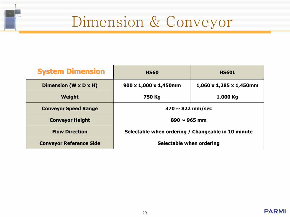
Dimension & Conveyor
HS60 HS60L
Dimension (W x D x H) 900 x 1,000 x 1,450mm 1,060 x 1,285 x 1,450mm
Weight 750 Kg 1,000 Kg
Conveyor Speed Range 370 ~ 822 mm/sec
Conveyor Height 890 ~ 965 mm
Flow Direction Selectable when ordering / Changeable in 10 minute
Conveyor Reference Side Selectable when ordering
System Dimension
- 30 -- 30 -
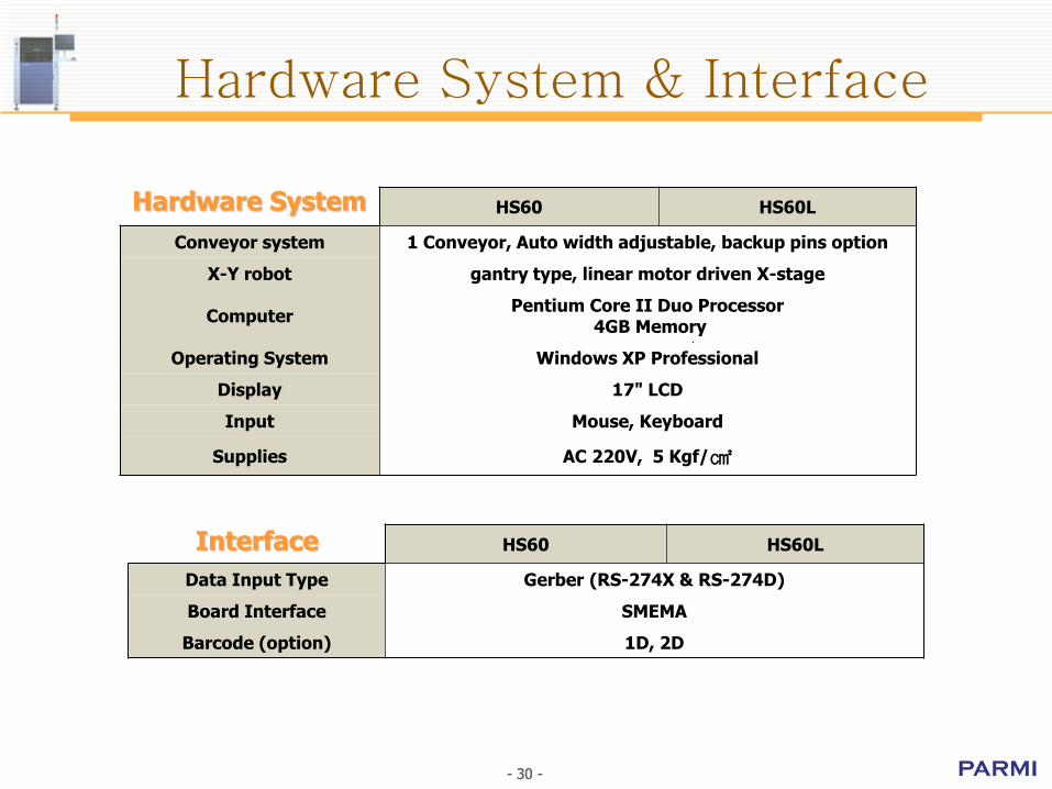
Hardware System & Interface
HS60 HS60L
Data Input Type Gerber (RS-274X & RS-274D)
Board Interface SMEMA
Barcode (option) 1D, 2D
Interface
HS60 HS60L
Conveyor system 1 Conveyor, Auto width adjustable, backup pins option
X-Y robot gantry type, linear motor driven X-stage
ComputerPentium Core II Duo Processor
4GB Memory
Operating System Windows XP Professional
Display 17" LCD
Input Mouse, Keyboard
Supplies AC 220V, 5 Kgf/㎠
Hardware System