spi bridge specifications 1 - eagle · pdf filework and coordination relating to bridge...
TRANSCRIPT
Eagle Specialized Coatings And Protected Enviroments - 18523 Fraser Hwy, Surrey, BC, CANADA V3S 8E7
(604) 576 - 2212(604) 576 - 7773Fax:
Tel:

Page 2
560-3.2 Pressure Wash System: Utilize a pressure wash system capable of removing all loose paint, loose rust and surface contamination. This is typically between 3500psi and 5000 psi. 560-3.3 Coating Application System: Use the coating application equipment in accordance with the coating manufacturer's published technical data requirements. 560-4 Environmental, Health and Safety Requirements. Isolate the work areas with containment devices, canvasses, tarpaulins or screens during all cleaning and coating operations. Dispose of all debris and waste products generated in accordance with all Federal, State and Local regulations. Requirements are covered in 560-16 and 560-17. If the above mentioned agencies do not have regulations on a particular jobsite, use care to protect the environment or moving vehicles. 560-5 Quality Control (QC). 560-5.1 Submittals: At least 60 calendar days prior to beginning coatings work, submit to the Engineer three copies of the Corporate Quality Control Plan approved under SSPC-QP1, site-specific Work Plan and a site-specific Coating QC Plan. Do not begin work until the site-specific Coating QC Plan has been approved by the Engineer. 560-5.2 Work Plan: Provide a written Work Plan describing all phases of the work and coordination relating to bridge painting operations, including coordination with the Coast Guard and maintenance of traffic. Include a Gantt chart depicting the milestone dates and individual project phases. Relate this plan to the site-specific Quality Control Plan. 560-5.3 Site-Specific Quality Control (QC) Plan: At a minimum, the site-specific QC plan shall include the following: Sample copies of inspection forms to be used; List of inspection equipment to be used: Description/scenario of testing procedures to ensure compliance with specification requirements regarding the job-specific QC testing (e.g. non-visible contamination testing, dry film thickness (DFT) testing etc.). 560-5.4 Inspection Equipment: Ensure that all inspection equipment is maintained in accordance with the manufacturer's instructions, calibrated, and in good working condition. 560-5.5 Documentation: The coating inspector shall maintain a daily log of all testing and QC observations. In addition to the daily log, prepare and maintain daily inspection reports at the job site. Provide inspection reports on a weekly basis and/or at the Engineer's request. Daily inspection reports shall include statements of conformance or nonconformance for each activity and corrective action procedures for each nonconformance issue identified (by CQC or Engineer). Provide copies of all audit reports prepared by SSPC within seven calendar days of receipt (if applicable).
Page 3
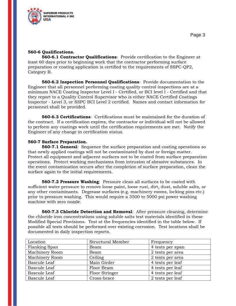
560-6 Qualifications. 560-6.1 Contractor Qualifications: Provide certification to the Engineer at least 60 days prior to beginning work that the contractor performing surface preparation or coating application is certified to the requirements of SSPC-QP2, Category B. 560-6.2 Inspection Personnel Qualifications: Provide documentation to the Engineer that all personnel performing coating quality control inspections are at a minimum NACE Coating Inspector Level I - Certified, or BCI level I - Certified and that they report to a Quality Control Supervisor who is either NACE Certified Coatings Inspector - Level 3, or SSPC BCI Level 2 certified. Names and contact information for personnel shall be provided. 560-6.3 Certifications: Certifications must be maintained for the duration of the contract. If a certification expires, the contractor or individual will not be allowed to perform any coatings work until the certification requirements are met. Notify the Engineer of any change in certification status. 560-7 Surface Preparation. 560-7.1 General: Sequence the surface preparation and coating operations so that newly applied coatings will not be contaminated by dust or foreign matter. Protect all equipment and adjacent surfaces not to be coated from surface preparation operations. Protect working mechanisms from intrusion of abrasive substances. In the event contamination occurs after the completion of surface preparation, clean the surface again to the initial requirements. 560-7.2 Pressure Washing: Pressure clean all surfaces to be coated with sufficient water pressure to remove loose paint, loose rust, dirt, dust, soluble salts, or any other contaminants. Degrease surfaces (e.g. machinery rooms, locking pins etc.) prior to pressure washing. This would require a 3500 to 5000 psi power washing machine with zero nozzle. 560-7.3 Chloride Detection and Removal: After pressure cleaning, determine the chloride iron concentrations using soluble salts test materials identified in these Modified Special Provisions. Test at the frequencies identified in the table below. If possible all tests should be performed over existing corrosion. Test locations shall be documented in daily inspection reports. Location Structural Member Frequency Flanking Span Beam 4 tests per span Machinery Room Beam 2 tests per area Machinery Room Ceiling 2 tests per area Bascule Leaf Main Girder 4 tests per leaf Bascule Leaf Floor Beam 4 tests per leaf Bascule Leaf Floor Stringer 4 tests per leaf Bascule Leaf Cross-brace 2 tests per leaf
Page 4
560-7.3.1 Surface Cleanliness (Chlorides): After pressure cleaning, ensure the chloride concentrations on cleaned surfaces do not exceed the levels in SSPC-SP 12, Table A1, NV-2. When the concentration measured exceeds the limits, re-clean the entire surface area and retest at the frequency required. If additional water washing does not reduce the contaminant concentration to acceptable levels, a surface treatment additive may be used. Before the use of a surface treatment additive, ensure the additive is approved by the coating system supplier and the Engineer. The coating manufacturer approves of the use of Chlor-Rid products for removal of salts and chloride levels. 560-7.4 Hand and Power Tool Cleaning: Visible rust and loose paint shall be prepared in accordance with SSPC-SP 2 or SSPC-SP 3. Any pack rust or scale, will need to be needle gunned or chipped down to surface rust to avoid moisture entrapment over the base surface of the metal. 560-8 Surfaces Not to be Coated. 560-8.1 Galvanized Surfaces: Do not coat galvanized surfaces unless it is washed with a citrus or simple green wash to remove the surface oils and or as specified in the Contract Documents. If rust is showing, power washing will clean the surface before encapsulating with RUST GRIP. 560-8.2 Concrete Surfaces: Do not coat concrete surfaces unless specified in the Contract Documents. Where concrete is showing Spalling and cracking from deterioration, the RUST GRIP product can be applied in heavy coats to penetrate into the cracks and Spalling areas to strengthen and stabilize the area. 560-9 Material Storage. Store coating materials in conformance with manufacturer's published recommendations. 560-10 Mixing and Thinning. Mix all coatings in accordance with the manufacturer's published recommendations. Only mix complete kits; partial kits shall not be used. Use thinners and solvents according to the manufacturer's published technical data requirements and confirm that the amount of thinner added does not cause the coating to exceed Volatile Organic Compound (VOC) regulations. Perform all mixing operations over an impervious surface and control against spills. If spills occur, clean them up immediately. Only trained personnel shall mix coatings. Personnel mixing coating shall have copies of product data sheets for each material being mixed in their possession at the time of mixing. 560-11 Application of Coatings. 560-1.1 General: Prior to the application of any coating, inspect the substrate for contamination and defects. Apply the coating(s) per manufacturer's published technical data requirements. Application with brushes and rollers will be permitted for application of stripe coat, touchup of spray application or when approved by the Engineer. Finish coat color shall be a "silver gray" and approved by the Engineer prior to application.
Page 5
560-11.1 Weather and Temperature Limitations for Field and Maintenance Coating: Do not apply coatings when contamination from rainfall is imminent or when the ambient air temperature, relative humidity, dew point temperature or temperature of the steel is outside the limits of the coating manufacturer's published recommendations. Do not employ spray application when the measured wind speed is above 15 miles per hour. 560-11.3 Application Quality Control: During application, measure the wet film thickness (WFT). After application of each coat, thoroughly inspect the surfaces for defects. Measure the dry film thickness (DFT) in accordance with SSPC-PA 2. When the DFT is deficient or excessive, correct to the appropriate thickness in accordance with the manufacturer's written recommendations and retest the area. Note: Due to the limitations of DFT testing of overcoat paint system, DFT testing may be required to be in accordance with ASTM D 4138, Measurement of Dry Film Thickness of Protective Coating Systems by Destructive Means, will be performed at the discretion of the Engineer. If destructive testing is performed, touch-up will be required (minimum of two coats per test area). Another method would be to measure the DFT of the existing coating and then take this in consideration when measuring the final DFT of the RUST GRIP system. 560-11.4 Stripe Coating: Prior to the coating application, apply a stripe coat to all crevices, welds, corners (inside and outside corners), sharp edges (e.g. radius less than 1/16-inch), bolts, nuts, rivets and rusted surfaces. The stripe coat shall be applied "un-thinned" and result in total opacity of the coated area. The stripe coat material shall have a discernable color contrast with the substrate. It will match the color of the finish coat. 560-11.5 Sealing Using Caulk: After striping and prior to coating application, completely seal the perimeter of all faying surfaces, cracks and crevices, joints open less than ½ inch, and skip-welded joints. Apply the caulk to the joint in accordance with caulking and coating manufacturer's recommendations. Ensure the caulk bead is tooled to a smooth and uniform finish and is cured according to the manufacturer's recommendation prior to the finish coat application. 560-11.6 Coating, Drying and Curing: Apply all coat(s) (including striping) within the manufacturer's published times for drying and recoating. Finish coat shall be applied to a minimum DFT of 5.0 mils / 10.0 wet mils (160 sq.ft./gallon) over normal surfaces. If a surface has been coated previously with standard three coat systems or old urethane systems and is peeling and cracking, a commercial blast or 5000 psi power wash is used to remove the flaking old materials down to the surface rust of 1/16". This surface will have to be coated with a solvent approved brush and working the RUST GRIP into the surface of the remaining surface rust and deteriorated steel surface keeping the brush constantly wet with coating. This procedure will have to be applied three times until the coating is not being absorbed and pinhole areas stop appearing. The three coats can be applied one after the other before moving from a section. Then a final coat will be rolled to assure enough coating is covering the surface to assure no pinholes can develop. This particular type of surface area described here has the appearance of a porous metal surface on the beam and will absorb coating very quickly leaving pinholes. This is why additional time and

Page 6
effort must be used to have the surface coated correctly and thoroughly to apply enough coating to allow absorption and prevent pinholes. This type of surface even when sandblasted (SSPC -SP10) is subject to additional effort for a coating to be applied. The application rate could be 80 sq.ft./gallon over this worst case scenario to allow absorption and covering. 560-11.7 Protection of Adjacent Surfaces: Protect all surfaces and working mechanisms not intended to be coated, during the application of coatings. Clean surfaces that have been contaminated with coatings until all traces of the coating have been removed. Do not allow material from cleaning and coating operations to be dispersed outside the work area. 560-12 Correcting Damaged or Defective Coatings. The Engineer will have final authority concerning the coating's uniformity and acceptable appearance. Additional finish coats may be required based on the cosmetic appearance of the coated surfaces. If additional coats are required at a later date, the surface must be roughed up with 220 grit or commercial blast to allow for adhesion of a final coat. 560-13 Protection of the Environment, Public and Workers. When working in areas under removal guidelines. 560-13.1 General: Establish plans and programs to protect the environment, public and workers from exposure to toxic heavy metals as well as released and emissions of hazardous materials, nuisance dusts and contaminated wash water. Conduct operations in compliance with United States Environmental Protection Agency (EPA), Occupational Health and Safety Administration (OSHA), and other applicable Federal, State and local regulations. 560-13.2 Protection of the Public and Environment: Prepare and submit to the Engineer plans and programs for protection of the environment and public based on the applicable requirements from EPA, this Specification, and the Contract Documents. Include plans for the protection of air and water. 560-13.2.1 Ambient Air Quality Compliance and Protection of the Air: 560-16.2.1.1 Visible Emissions: During pressurized water cleaning, do not allow visible emissions from the containment to exceed a random cumulative duration of more than ten percent of the workday - SSPC Guide 6 Level 3 Emissions. Determine the visible emissions using EPA Method 22, Timing of Emissions as defined by 40 CFR 60, Appendix A. 560-13.3 Regulated Area: Establish a regulated area around the work site to protect and prohibit unauthorized persons from areas where exposure to hazardous airborne metals may exceed the following action levels: Lead (30 g/m3) Cadmium (2.5 g/m3) Arsenic (5 g/m3) Hexavalent Chromium (Cr 6+) (2.5 g/m3)

Page 7
Conduct Monitoring in accordance with National Institute for Occupational Safety and Health (NIOSH) procedures upon the initiation of the dust producing operations and submit the test results to the Engineer within 72 hours of sampling. Report sample results as eight-hour time weighted averages (TWA). Re-established the regulated and perform additional sampling when the results exceed the action levels or when directed by the Engineer. Document all pertinent data in a field log book. Position air sampling pumps around the project perimeter at locations where the public or personnel can approach the work area. Place sampler inlets at breathing height. Clearly delineate the regulated area by the use of warning signs, rope, barrier tape, or temporary construction fencing. 560-13.4 Water Quality: Do not release, discharge or otherwise cause hazardous materials, debris, waste or paint chips to enter the water. Protect against releases due to inclement weather and bridge movement from entering the body of water below the bridge. 560-13.5 Pollution Control: Submit a written pollution control and monitoring plan at the preconstruction meeting which clearly describes the means for complying with all Local, State and Federal regulations including pollution control provisions specified herein. The written plan must be in accordance with Project Design: Industrial lead Paint Removal Handbook, Volume II, Phase 6, Environmental Monitoring, specifically include, but not limited to, providing a scaled map of the worksite layout showing the waste storage areas, staging areas, and temporary waste storage areas. Immediately cease all operations in the event a violation of any environmental regulation occurs or failure to properly execute any pollution control provisions. Operations will only resume after written proposed corrective procedures have been submitted to and approved by the Engineer and subsequently implemented. In the case of encapsulation using RUST GRIP, there will not be any paint removal as described in abatement procedures. Only in areas of scale or pack rust removal will catches be made of removed paints unless chips are blown off that must be in a catch system. 560-13.6 Containment Systems: Submit a written containment system design plan at the preconstruction meeting, which clearly describes the proposed containment system applicable to the intended removal method and in accordance with the requirements outlined herein and SSPC Guide 6. The category and class of containment shall be a minimum of SSPC Guide 6, 2W. Ensure the plan includes, but not be limited to, removal method, methods for collecting debris and containment enclosure components. Ensure that under no circumstances any liquid, paint, paint chips, or other debris falls outside of the containment area. Fire retardant materials shall be utilized. 560-13.6.1 Structural Load Requirements: Provide containment drawings, calculations, and assumptions, including ventilation criteria if applicable, signed and sealed by a Specialty Engineer registered in the State of the project. Provide a complete structural impact analysis prepared by a Specialty Engineer to verify the existing structure can withstand the live and dead loads imposed upon the structure by the containment system. All drawings and calculations must be submitted and accepted before any work begins. Repair any damage created by

Page 8
fastening, bracing, or handling the scaffolding and/or staging, or any surrounding property at no cost to the DOT Department. 560-13.6.2 Work Area Lighting: Ensure the lighting inside the contained work area is in accordance with SSPC Guide 12. Provide lighting to a minimum of 10 foot-candles for general, 20 foot-candles for work, and 50 foot-candles for inspection. 560-13.6.3 Access: If a suspended platform is constructed, verify the platform and its components are designed and constructed to support at least four times its maximum intended load without failure. In addition, wire cables shall be capable of supporting at least six times their maximum intended load without failure. Comply with all applicable OSHA regulations regarding ladders and scaffolding. Worker tie-off cables shall be installed to accommodate 100-percent tie-off (if required). 560-13.7 Protection of Adjacent Areas: Protect all areas adjacent to work areas including deck grating, tender house, motors and gears. Before the commencement of any cleaning and coating operations, provide a control plan for the protection of adjacent surfaces from damage by surface preparation and coating to the Engineer for review. Repair any damage to adjacent areas at no expense to the DOT Department. The repair procedure must be submitted to the Engineer for acceptance prior to remediation. 560-13.8 Worker Protection: Comply with the requirements of OSHA 29 CFR Part 1926 and applicable portions of 29 CFR 1910. Include specific programs as required by Parts 1926.62 (lead), 29 CFR 1926.1118 (inorganic arsenic), 29 CFR 1926.1126 (hexavalent chromium), and 29 CFR Part 1926.1127 (cadmium) when these hazardous agents are present. Implement appropriate safety procedures for all identified hazards on the job site whether specifically identified herein or not. 560-14 Waste Handling and Management. Prepare a waste management program plan which addresses the applicable requirements from EPA regulations for hazardous waste management and the Contract Documents. Include provisions for the handling and disposal of non-hazardous construction waste. 560-14.1 Collection and Handling of Waste: Properly classify, package and store, all paint removal debris, both solid and liquid in accordance with SSPC Guide 7, The Federal Water Pollution Control Act with amendments, and all other current government regulations and guidelines. Comply with the Resource Conservation and Recovery Act to include, at a minimum, CFR 40, parts 260 268. Keep solid and liquid waste separate and individual waste streams separate prior to identification, storage, transportation and disposal. 560-14.2 Testing and Analysis: Laboratory analyses for all waste streams and environmental samples shall be conducted by an EPA certified, independent laboratory with an approved Quality Assurance Plan. Lab analyses for worker monitoring and regulated area samples shall be conducted by an AIHA metals-
Page 9
accredited laboratory. Provide a copy of all sampling and test reports no later than 72 hours after collection of samples. 560-14.2 Waste identification: Collect samples in accordance with U.S. Environmental Protection Agency - SW846, Test Methods for Evaluating Solid Waste - Physical/Chemical Methods. Use a random and representative sampling technique. Collect a minimum of four representative samples of each waste stream. These waste streams include, but are not limited to, wash water and paint chips. Complete the initial sampling of each waste stream immediately upon filling the first drum, but do not allow waste to accumulate for longer than 7 days before sampling. After the representative samples are collected, send them immediately to the EPA certified laboratory for analysis. Once each waste stream is sampled, tested and classified, additional sampling and analysis are not required for subsequent shipments unless the waste stream changes or otherwise directed by the Engineer, required by State regulations, or required by the waste recycling or disposal facility. Submit samples to an approved laboratory to be tested for arsenic, barium, cadmium, chromium, lead, mercury, selenium and silver in accordance with EPA Methods 3050 and 6010 (content) and EPA Method 1311, Toxicity Characteristics Leaching Procedures (TCLP). Clearly label each sample with sample number, date and time of sampling, name of collector, and location of collection. Maintain a chain of custody form for each sample including duplicate samples provided to the Engineer. For each round of testing, prepare a Sample Analysis Request Form with sample numbers, type of waste, amount of each sample, date of sampling and distribution of samples. 560-14.4 Waste Storage: Collect waste from the control devices, equipment, and all work surfaces on a daily basis. Keep hazardous and non-hazardous waste separate. Do not mix blasting debris with any other type of waste. Place waste in approved storage drums. Locate all hazardous waste within a regulated area. The maximum weight for each drum, when filled, is 821 pounds. Properly seal and label all drums. Transport waste storage drums to a secured, marked, temporary storage area. Locate the temporary storage area on well-drained ground not susceptible to flooding or storm water run-off. Place drums on pallet and cover with fiber reinforced, impermeable tarpaulins. Store drums no more than two drums wide and two drums high. Arrange drums so that labels are visible and easily read. Do not store waste in the temporary storage area longer than 90 days. 560-14.5 Waste Disposal: Transport, treat and dispose of hazardous and non-hazardous waste. Notify the Engineer a minimum of three weeks prior to the shipment of any waste to an off-site facility. Provide the Engineer with documentation that the receiving disposal facility is properly licensed. In addition provide manifests for all hazardous and non-hazardous waste shipments. 560-14.6 Permits: The Contractor is responsible for all liability resulting from non-compliance with pertinent rules and regulations including permit requirements. 560-15 Warranty. Prior to final acceptance, provide a warranty bond that covers all costs (labor and materials) to replace deficient coatings using the criterion outlined below. Within a two year period, if any of the following failure modes are identified, the application