spherical plain bearings,plain bushes, rod ends- sferni lezajevi
DESCRIPTION
Spherical plain bearings,plain bushes, rod ends, katalog sfernih ležajeva kompanije INATRANSCRIPT

Spherical plain bearings, plain bushes, rod ends
Catalogue 238
Titel_238_GB.qxd 10.10.2006 10:47 Uhr Seite 1
238
Since the introduction of the spherical plain bearing, ELGES spherical plain bearings and ELGES rod ends have had a decisive influence on the development and technological progress of these precision components. This led to extensive product innovations and many pioneering applications only became possible due to the know-how of the company group. Furthermore, the new maintenance-free ELGOGLIDE® bearings – as spherical plain bearings, cylindrical bushes or combinations of radial, angular contact and axial bearings – continue the tradition of this product group and at the same time represent state-of-the-art engineering and economical bearing solutions.Spherical plain bearings are ready-to-fit, standardised machine elements. The concave outer ring bore and the convex inner ring geometry allow spatial adjustment motion. The bearings can support static loads and are suitable for tilting and swivel motion. They can compensate for shaft misalignment, are not subject to edge stresses under misalignment and allow substantial manufacturing tolerances in the adjacent construction.Rod ends are spherical plain bearing units. They comprise a rod type housing, into which a spherical plain bearing is integrated, and have an external or internal thread. Rod ends are used as connecting levers and connecting rods and as connecting elements between cylinders and their adjacent parts in hydraulic and pneumatic cylinders.Spherical plain bearings and rod ends are available in numerous designs, dimension series and versions. The ELGOGLIDE® types are maintenance-free – the types requiring maintenance are easily maintained – and extremely reliable in operation and have a long operating life.Catalogue 238 describes the range of ELGES spherical plain bearings and ELGES rod ends. It has been completely revised from Catalogue 236. Any information in previous editions which does not concur with the data in this edition is therefore invalid. The principal changes relate to the maintenance-free sliding material ELGOGLIDE®.These are:■ increased basic load ratings■ extended sliding travel.This gives a significant increase in bearing life.In addition to the catalogue, the INA CD medias® professional represents a further service. This CD is designed as an advisory system. It contains an information section giving detailed product descriptions, selected application examples with design guidelines, calculation software and a lexicon of terminology relevant to rolling bearing technology. Please contact INA for a copy of this CD.
Schaeffler KGHerzogenaurach (Germany)
Spherical plain bearings, plain bushes, rod ends

Maintenance-free cylindricalplain bushesZGB
GE..PWGE..DW-2RS2GE..DW
117
198
GE..ZOGE..PB GE..HO 2RS- GE..LO
117
195
GAKFR..PW GIKFR..PW
117
205
GIKFR..PBGAKFR..PB
117
201

Technical principles
Maintenance-free spherical plain bearingsRadial spherical plain bearingsLarge radial spherical plain bearings
Maintenance-freecylindrical plain bushes
Maintenance-free spherical plain bearingsAngular contact spherical plain bearingsAxial spherical plain bearings
Spherical plain bearings requiring maintenanceRadial spherical plain bearingsLarge radial spherical plain bearings
Spherical plain bearings requiring maintenanceAngular contact spherical plain bearingsAxial spherical plain bearings
Maintenance-free rod ends
Rod ends requiring maintenance
Hydraulic rod ends
AppendixOther products
GE..UKGE..FW GE..UK 2RS--GE..FW 2RS
117
199
GE..AW GE..SW
117
200
GE..DO 2RS GE..DOGE..FO 2RS- -GE..FO
117
196
GE..AX GE..SX
117
197
GAR..UK 2RS- GAR..UK GIR..UK 2RS- GIR..UK11
7 20
6
GIR..DOGIR..DO 2RS-GAR..DOGAR..DO 2RS-
117
202
GIHN K..LO-GIHR K..DO-GK..DOGF..DO
117
204

4
Page
2 Product range2 Overview
8 Product index
12 Ordering designation
13 Index of suffixes
14 Symbols and units
17 Technical principles17 Load carrying capacity and life17 Spherical plain bearings and rod ends17 Cylindrical plain bushes17 Concentric constant load F18 Equivalent load18 Combined radial and axial load19 Variable bearing load19 Calculation of rating life20 Basic load ratings, contact pressure20 Basic dynamic load rating21 Basic static load rating21 Contact pressure22 Predimensioning24 Bearing motion, life24 Motion parameter – swivel angle and tilt angle25 Rotary motion25 Frequency of motion25 Intermittent operation25 Life25 Operating life
26 Friction26 Friction behaviour of spherical plain bearings requiring maintenance,
maintenance-free spherical plain bearings and maintenance-free cylindrical plain bushes
28 Lubrication28 Functions of the lubricant28 Grease lubrication29 Running-in phase29 Relubrication29 Maintenance-free spherical plain bearings, plain bushes and rod ends
Contents

5
Page
30 Internal clearance and operating clearance30 Internal clearance30 Radial internal clearance of radial spherical plain bearings requiring maintenance
with steel/steel sliding contact surface30 Axial internal clearance32 Internal clearance of cylindrical plain bushes33 Fits related to practical use for spherical plain bearings34 Operating clearance34 Influence of interference on the radial internal clearance of
radial spherical plain bearings36 Calculation example
37 Design of bearing arrangements37 Radial location of spherical plain bearings and
maintenance-free cylindrical plain bushes37 Spherical plain bearings requiring maintenance37 Maintenance-free spherical plain bearings37 Application as locating bearings37 Application as non-locating bearings (between shaft and bearing bore)38 Axial location of spherical plain bearings38 Location of bearing rings39 Design of adjacent components39 Chamfer dimensions39 Quality of shaft and housing bore
40 Sealing
42 Fitting and dismantling42 Fitting42 Delivered condition42 Storage42 Removal from packaging43 Tools for heat assisted fitting43 Checking the adjacent construction44 Rules and guidelines46 Dismantling
47 Operating temperatures
48 Materials48 Maintenance-free spherical plain bearings49 Maintenance-free cylindrical plain bushes50 Spherical plain bearings requiring maintenance50 Rod ends
51 ISO tolerances

6
Page
54 Product range54 Maintenance-free spherical plain bearings/
maintenance-free cylindrical plain bushes54 Criteria for bearing selection
56 Radial spherical plain bearings56 Features
58 Angular contact spherical plain bearings58 Features
58 Axial spherical plain bearings58 Features
59 Maintenance-free cylindrical plain bushes59 Features
60 Design and safety guidelines63 Calculation of rating life64 for maintenance-free spherical plain bearings – sliding material ELGOGLIDE®
66 for maintenance-free spherical plain bearings – sliding material PTFE composite67 for maintenance-free spherical plain bearings – sliding material PTFE-bronze film70 Calculation examples72 Calculation of rating life72 for maintenance-free cylindrical plain bushes – sliding material ELGOGLIDE®
73 Calculation example
74 Accuracy
75 Special designs
75 Ordering example and ordering designation
76 Dimension tables
90 Spherical plain bearings requiring maintenance90 Criteria for bearing selection
92 Radial spherical plain bearings92 Features
94 Angular contact spherical plain bearings94 Features
94 Axial spherical plain bearings94 Features
95 Design and safety guidelines97 Calculation of rating life97 for radial and angular contact spherical plain bearings
with steel/steel sliding contact surface98 for steel/bronze sliding contact surface
100 Calculation examples
Contents
7
Page
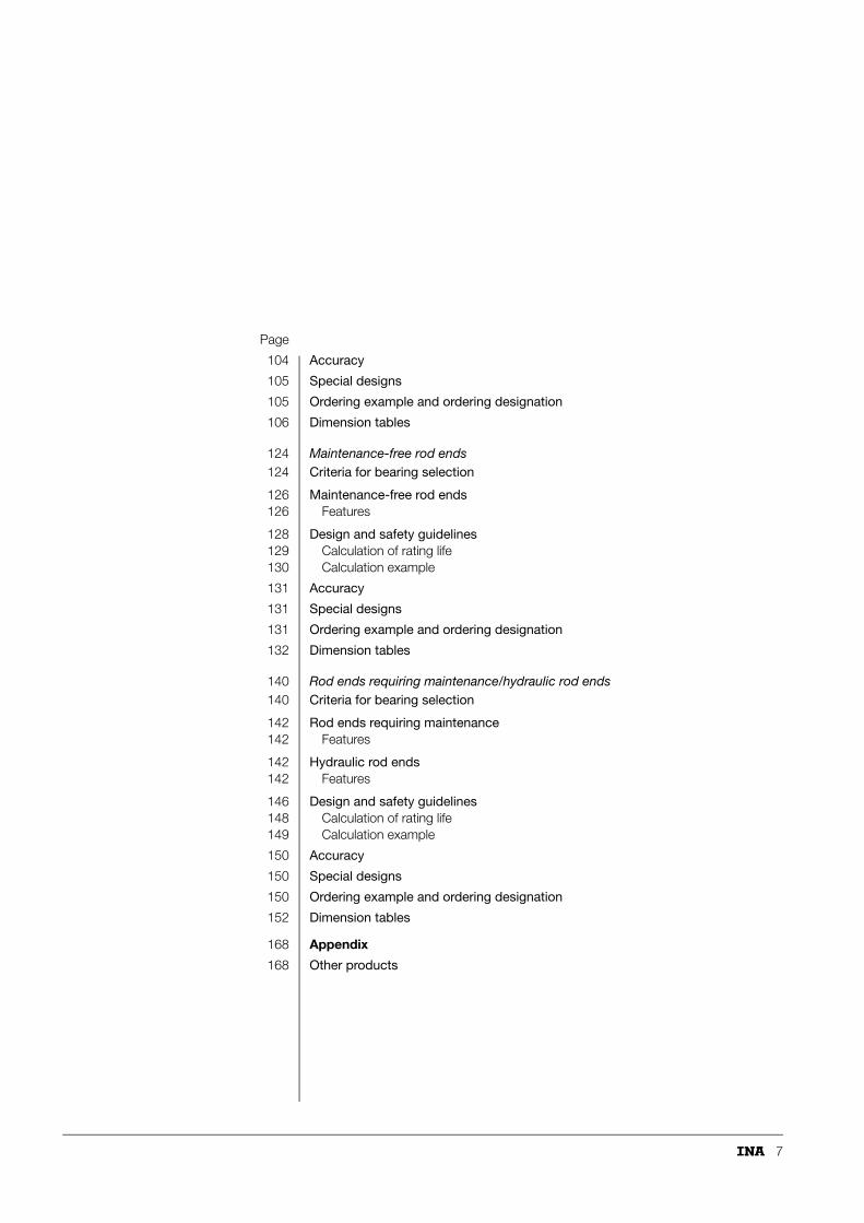
104 Accuracy
105 Special designs
105 Ordering example and ordering designation
106 Dimension tables
124 Maintenance-free rod ends124 Criteria for bearing selection
126 Maintenance-free rod ends126 Features
128 Design and safety guidelines129 Calculation of rating life130 Calculation example
131 Accuracy
131 Special designs
131 Ordering example and ordering designation
132 Dimension tables
140 Rod ends requiring maintenance/hydraulic rod ends140 Criteria for bearing selection
142 Rod ends requiring maintenance142 Features
142 Hydraulic rod ends142 Features
146 Design and safety guidelines148 Calculation of rating life149 Calculation example
150 Accuracy
150 Special designs
150 Ordering example and ordering designation
152 Dimension tables
168 Appendix
168 Other products

8
Product indexsorted alphanumerically
FeaturesPage
Tablesfrom page Type Description
143 158 GAKFL..PB Rod end requiring maintenance to ISO 12 240-4, dimension series K, type M, sliding contact surface steel/bronze, shank with external thread, left hand thread
127 138 GAKFL..PW Maintenance-free rod end to ISO 12 240-4, dimension series K, type M, sliding contact surface steel/PTFE-bronze film, shank with external thread, left hand thread
143 158 GAKFR..PB Rod end requiring maintenance to ISO 12 240-4, dimension series K, type M, sliding contact surface steel/bronze, shank with external thread, right hand thread
127 138 GAKFR..PW Maintenance-free rod end to ISO 12 240-4, dimension series K, type M, sliding contact surface steel/PTFE-bronze film, shank with external thread, right hand thread
143 154 GAL..DO Rod end requiring maintenance to ISO 12 240-4, dimension series E, type M, sliding contact surface steel/steel, shank with external thread, left hand thread
143 154 GAL..DO-2RS Rod end requiring maintenance to ISO 12 240-4, dimension series E, type M, sliding contact surface steel/steel, shank with external thread, left hand thread, lip seals on both sides
127 134 GAL..UK Maintenance-free rod end to ISO 12 240-4, dimension series E, type M, sliding contact surface hard chromium/PTFE composite, shank with external thread, left hand thread
127 134 GAL..UK-2RS Maintenance-free rod end to ISO 12 240-4, dimension series E, type M, sliding contact surface hard chromium/ELGOGLIDE®, shank with external thread, left hand thread, lip seals on both sides
143 154 GAR..DO Rod end requiring maintenance to ISO 12 240-4, dimension series E, type M, sliding contact surface steel/steel, shank with external thread, right hand thread
143 154 GAR..DO-2RS Rod end requiring maintenance to ISO 12 240-4, dimension series E, type M, sliding contact surface steel/steel, shank with external thread, right hand thread, lip seals on both sides
127 134 GAR..UK Maintenance-free rod end to ISO 12 240-4, dimension series E, type M, sliding contact surface hard chromium/PTFE composite, shank with external thread, right hand thread
127 134 GAR..UK-2RS Maintenance-free rod end to ISO 12 240-4, dimension series E, type M, sliding contact surface hard chromium/ELGOGLIDE®, shank with external thread, right hand thread, lip seals on both sides
58 86 GE..AW Maintenance-free axial spherical plain bearing to ISO 12 240-3, sliding contact surface hard chromium/ELGOGLIDE®
94 122 GE..AX Axial spherical plain bearing requiring maintenance to ISO 12 240-3, sliding contact surface steel/steel
9
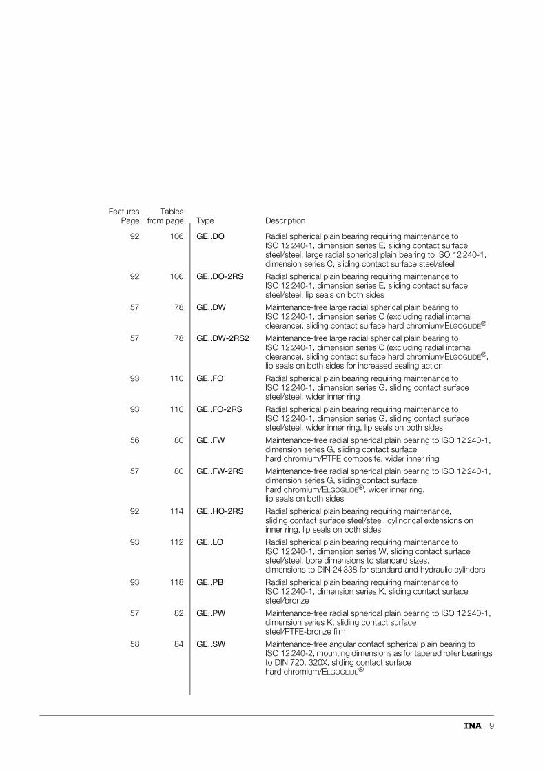
92 106 GE..DO Radial spherical plain bearing requiring maintenance to ISO 12 240-1, dimension series E, sliding contact surface steel/steel; large radial spherical plain bearing to ISO 12 240-1, dimension series C, sliding contact surface steel/steel
92 106 GE..DO-2RS Radial spherical plain bearing requiring maintenance to ISO 12 240-1, dimension series E, sliding contact surface steel/steel, lip seals on both sides
57 78 GE..DW Maintenance-free large radial spherical plain bearing to ISO 12 240-1, dimension series C (excluding radial internal clearance), sliding contact surface hard chromium/ELGOGLIDE®
57 78 GE..DW-2RS2 Maintenance-free large radial spherical plain bearing to ISO 12 240-1, dimension series C (excluding radial internal clearance), sliding contact surface hard chromium/ELGOGLIDE®, lip seals on both sides for increased sealing action
93 110 GE..FO Radial spherical plain bearing requiring maintenance to ISO 12 240-1, dimension series G, sliding contact surface steel/steel, wider inner ring
93 110 GE..FO-2RS Radial spherical plain bearing requiring maintenance to ISO 12 240-1, dimension series G, sliding contact surface steel/steel, wider inner ring, lip seals on both sides
56 80 GE..FW Maintenance-free radial spherical plain bearing to ISO 12 240-1, dimension series G, sliding contact surface hard chromium/PTFE composite, wider inner ring
57 80 GE..FW-2RS Maintenance-free radial spherical plain bearing to ISO 12 240-1, dimension series G, sliding contact surface hard chromium/ELGOGLIDE®, wider inner ring, lip seals on both sides
92 114 GE..HO-2RS Radial spherical plain bearing requiring maintenance, sliding contact surface steel/steel, cylindrical extensions on inner ring, lip seals on both sides
93 112 GE..LO Radial spherical plain bearing requiring maintenance to ISO 12 240-1, dimension series W, sliding contact surface steel/steel, bore dimensions to standard sizes, dimensions to DIN 24 338 for standard and hydraulic cylinders
93 118 GE..PB Radial spherical plain bearing requiring maintenance to ISO 12 240-1, dimension series K, sliding contact surface steel/bronze
57 82 GE..PW Maintenance-free radial spherical plain bearing to ISO 12 240-1, dimension series K, sliding contact surface steel/PTFE-bronze film
58 84 GE..SW Maintenance-free angular contact spherical plain bearing to ISO 12 240-2, mounting dimensions as for tapered roller bearings to DIN 720, 320X, sliding contact surface hard chromium/ELGOGLIDE®
FeaturesPage
Tablesfrom page Type Description
10
Product index
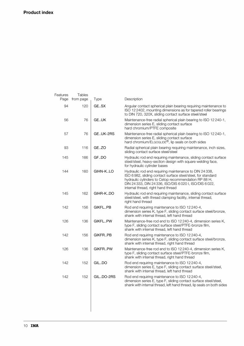
94 120 GE..SX Angular contact spherical plain bearing requiring maintenance to ISO 12 2402, mounting dimensions as for tapered roller bearings to DIN 720, 320X, sliding contact surface steel/steel
56 76 GE..UK Maintenance-free radial spherical plain bearing to ISO 12 240-1, dimension series E, sliding contact surface hard chromium/PTFE composite
57 76 GE..UK-2RS Maintenance-free radial spherical plain bearing to ISO 12 240-1, dimension series E, sliding contact surface hard chromium/ELGOGLIDE®, lip seals on both sides
93 116 GE..ZO Radial spherical plain bearing requiring maintenance, inch sizes, sliding contact surface steel/steel
145 166 GF..DO Hydraulic rod end requiring maintenance, sliding contact surface steel/steel, heavy-section design with square welding face,for hydraulic cylinder bases
144 160 GIHN-K..LO Hydraulic rod end requiring maintenance to DIN 24 338, ISO 6 982, sliding contact surface steel/steel, for standard hydraulic cylinders to Cetop recommendation RP 88 H, DIN 24 333, DIN 24 336, ISO/DIS 6 020 I, ISO/DIS 6 022, internal thread, right hand thread
145 162 GIHR-K..DO Hydraulic rod end requiring maintenance, sliding contact surface steel/steel, with thread clamping facility, internal thread, right hand thread
142 156 GIKFL..PB Rod end requiring maintenance to ISO 12 240-4, dimension series K, type F, sliding contact surface steel/bronze, shank with internal thread, left hand thread
126 136 GIKFL..PW Maintenance-free rod end to ISO 12 240-4, dimension series K, type F, sliding contact surface steel/PTFE-bronze film, shank with internal thread, left hand thread
142 156 GIKFR..PB Rod end requiring maintenance to ISO 12 240-4, dimension series K, type F, sliding contact surface steel/bronze, shank with internal thread, right hand thread
126 136 GIKFR..PW Maintenance-free rod end to ISO 12 240-4, dimension series K, type F, sliding contact surface steel/PTFE-bronze film, shank with internal thread, right hand thread
142 152 GIL..DO Rod end requiring maintenance to ISO 12 240-4, dimension series E, type F, sliding contact surface steel/steel, shank with internal thread, left hand thread
142 152 GIL..DO-2RS Rod end requiring maintenance to ISO 12 240-4, dimension series E, type F, sliding contact surface steel/steel, shank with internal thread, left hand thread, lip seals on both sides
FeaturesPage
Tablesfrom page Type Description
11
126 132 GIL..UK Maintenance-free rod end to ISO 12 240-4, dimension series E, type F, sliding contact surface hard chromium/PTFE composite, shank with internal thread, left hand thread
126 132 GIL..UK-2RS Maintenance-free rod end to ISO 12 240-4, dimension series E, type F, sliding contact surface hard chromium/ELGOGLIDE®, shank with internal thread, left hand thread, lip seals on both sides
126 136 GIPFR..PW Maintenance-free rod end to ISO 12 240-4, dimension series K, type F, sliding contact surface steel/PTFE-bronze film, shank with internal thread (fine pitch thread for standard pneumatic cylinders to DIN 24 335), right hand thread
142 152 GIR..DO Rod end requiring maintenance to ISO 12 240-4, dimension series E, type F, sliding contact surface steel/steel, shank with internal thread, right hand thread
142 152 GIR..DO-2RS Rod end requiring maintenance to ISO 12 240-4, dimension series E, type F, sliding contact surface steel/steel, shank with internal thread, right hand thread, lip seals on both sides
126 132 GIR..UK Maintenance-free rod end to ISO 12 240-4, dimension series E, type F, sliding contact surface hard chromium/PTFE composite, shank with internal thread, right hand thread
126 132 GIR..UK-2RS Maintenance-free rod end to ISO 12 240-4, dimension series E, type F, sliding contact surface hard chromium/ELGOGLIDE®, shank with internal thread, right hand thread, lip seals on both sides
144 164 GK..DO Hydraulic rod end requiring maintenance to ISO 12 240-4, dimension series E, type S, sliding contact surface steel/steel, circular welding face, concentric locating pin on shank base and 45° welding chamfer, for piston rod ends and cylinder bases
59 88 ZGB Maintenance-free cylindrical plain bush to ISO 4 379, sliding layer made from ELGOGLIDE®
FeaturesPage
Tablesfrom page Type Description

12
Ordering designation
The ordering designation gives an abbreviated description of the product.It consists of:■ the designation and■ suffixes.
Marking on the productDo not use the marking on the bearing for ordering. It may be incomplete or not sufficiently specific.
Designation (Figure 1 and 2)Every product has a designation. This is given in the dimension tables and describes the standard design of the bearing.The designation consists of several parts.It indicates:■ the design – the type of product
(spherical plain bearing, rod end, plain bush)■ the dimensional component – the bore diameter■ the type of sliding contact surface.Product index, see page 8.
Suffixes (Figure 1 and 2)The suffixes are placed after the designation.They supplement the designation and indicate:■ variants on the standard design,
e.g. lip seals on both sides 2RS■ special designs.
Special designs are possible only by agreement.Index of suffixes, see page 13.
Ordering the product (Figure 1 and 2)Ordering procedure: ■ determine the product type required■ take the ordering designation from the dimension table.
The correct sequence of characters must be observed when ordering.
Further ordering examples are given in the product sections.
Figure 1 · Radial spherical plain bearing requiring maintenance, lip seals on both sides – designation and suffixes
Figure 2 · Maintenance-free rod end, lip seals on both sides – designation and suffixes
d
GE 40 DO-2RS
117
137
GIR 40 UK-2RS
d
118
077

13
Index of suffixes
Suffixes Description
C2 Radial internal clearance smaller than normal (for spherical plain bearings requiring maintenance)
C3 Radial internal clearance larger than normal (for spherical plain bearings requiring maintenance)
2RS Lip seals on both sides
2RS1 High performance seals on both sides
2RS2 Increased sealing action on both sides for large radial spherical plain bearings
F10 Angular contact spherical plain bearing GE..SX with lubrication groove system for oil bath lubrication
W3 Maintenance-free radial spherical plain bearing with inner ring made from corrosion-resistant steel
W7 Maintenance-free radial spherical plain bearing, inner ring bore with ELGOGLIDE® lining, giving dNew = d – 1,08
W8 Inner ring bore with ELGOGLIDE® lining, dNew = d
14
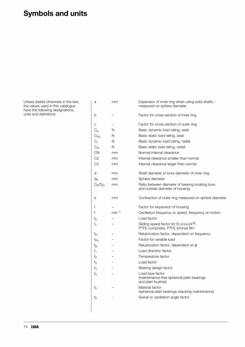
Symbols and units
Unless stated otherwise in the text, the values used in this catalogue have the following designations, units and definitions:
a mm Expansion of inner ring when using solid shafts – measured on sphere diameter
b – Factor for cross-section of inner ring
c – Factor for cross-section of outer ring
Ca N Basic dynamic load rating, axial
C0a N Basic static load rating, axial
Cr N Basic dynamic load rating, radial
C0r N Basic static load rating, radial
CN mm Normal internal clearance
C2 mm Internal clearance smaller than normal
C3 mm Internal clearance larger than normal
d mm Shaft diameter or bore diameter of inner ring
dK mm Sphere diameter
DA/DG mm Ratio between diameter of bearing locating bore and outside diameter of housing
e mm Contraction of outer ring measured on sphere diameter
f – Factor for expansion of housing
f min–1 Oscillation frequency or speed, frequency of motion
fb – Load factor
fv – Sliding speed factor for ELGOGLIDE®, PTFE composite, PTFE-bronze film
fH – Relubrication factor, dependent on frequency
fHz – Factor for variable load
f� – Relubrication factor, dependent on �
f1 – Load direction factor
f2 – Temperature factor
f3 – Load factor
f4 – Bearing design factor
f5 – Load type factor(maintenance-free spherical plain bearings and plain bushes)
f5 – Material factor(spherical plain bearings requiring maintenance)
f6 – Swivel or oscillation angle factor

15
FA N Axial bearing load
FR N Radial bearing load
Fmax N Maximum bearing load
Fmin N Minimum bearing load
K N/mm2 Specific load parameter
lW osc. Maintenance interval between two lubrication operations
lhW h Maintenance interval between two lubrication operations
L osc. Theoretical life with single initial lubrication (spherical plain bearings requiring maintenance)
L osc. Theoretical life under constant load (maintenance-free spherical plain bearings and plain bushes)
Lh h Theoretical life under constant load (maintenance-free spherical plain bearings and plain bushes)
Lh h Theoretical life taking account of variable conditions
Lh h Theoretical life with single initial lubrication (spherical plain bearings requiring maintenance)
LhN h Theoretical life with periodic relubrication
LhW h Theoretical life under variable load
Lh1, Lh2 h Theoretical life for individual time periods
LN osc. Theoretical life with periodic relubrication
LW osc. Theoretical life under variable load
M Nm Bearing frictional torque
P N Equivalent bearing load
p N/mm2 Contact pressure (specific bearing load)
PHz Hz Load frequency
Pperm N Permissible load on rod end
Rz �m Mean roughness depth
s m Sliding distance
S mm Operating clearance
16
Symbols and units
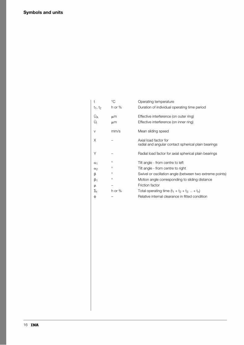
t °C Operating temperature
t1, t2 h or % Duration of individual operating time period
ÜA �m Effective interference (on outer ring)
Ül �m Effective interference (on inner ring)
v mm/s Mean sliding speed
X – Axial load factor for radial and angular contact spherical plain bearings
Y – Radial load factor for axial spherical plain bearings
�1 ° Tilt angle - from centre to left
�2 ° Tilt angle - from centre to right
� ° Swivel or oscillation angle (between two extreme points)
�1 ° Motion angle corresponding to sliding distance
� – Friction factor
�t h or % Total operating time (t1 + t2 + t3 .. + tn)
� – Relative internal clearance in fitted condition
17
Load carrying capacity and life
Spherical plain bearings and rod endsThe size of spherical plain bearing or rod end required depends on the requirements for:■ load carrying capacity■ motion■ rating life■ operational reliability.The direction and type of load determine:■ the bearing type■ the sliding contact surface.The load carrying capacity is measured in terms of: ■ the basic dynamic load rating Cr (Ca) (page 20)■ the basic static load rating C0r (C0a) (page 21).
Cylindrical plain bushesThe principal factors influencing the dimensioning of cylindrical plain bushes and their life calculation include:■ the magnitude and type of load■ the motion of the bearing■ the frequency of motion■ the load frequency under pulsating or alternating load.The load carrying capacity is measured in terms of:■ the basic dynamic load rating Cr (page 20)■ the basic static load rating C0r (page 21).
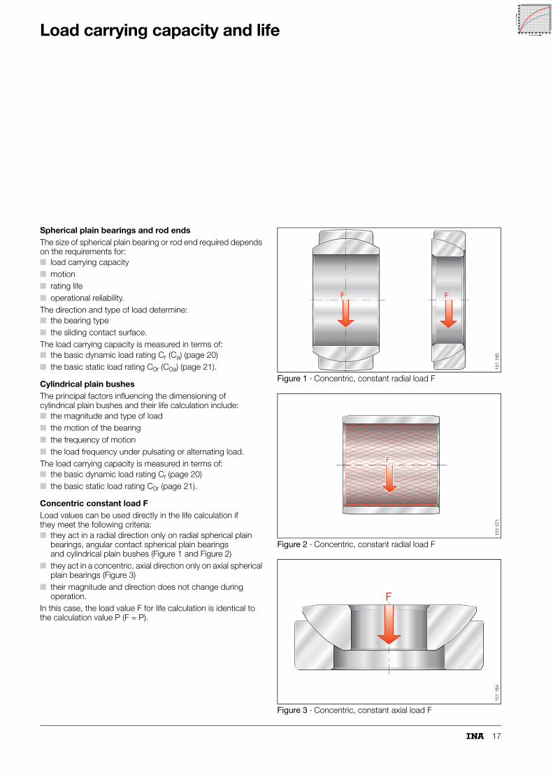
Concentric constant load FLoad values can be used directly in the life calculation if they meet the following criteria:■ they act in a radial direction only on radial spherical plain
bearings, angular contact spherical plain bearings and cylindrical plain bushes (Figure 1 and Figure 2)
■ they act in a concentric, axial direction only on axial spherical plain bearings (Figure 3)
■ their magnitude and direction does not change during operation.
In this case, the load value F for life calculation is identical to the calculation value P (F = P).
Figure 1 · Concentric, constant radial load F
Figure 2 · Concentric, constant radial load F
Figure 3 · Concentric, constant axial load F
F F
151
185
F
151
571
F
151
184

18
Load carrying capacity and life
Equivalent load
Combined radial and axial loadIf spherical plain bearings are subjected simultaneously to radial and axial loads, the equivalent calculation value P must be used in the life formula.This value has the same effect on the life as the combined loads themselves.The value P is determined using the following formulae: ■ radial and angular contact spherical plain bearings
(Figure 4 and 5):
■ axial spherical plain bearings (Figure 6):
P NEquivalent dynamic bearing load
FR NRadial bearing load
FA NAxial bearing load
X –Axial load factor for radial and angular contact spherical plain bearings
Y –Radial load factor for axial spherical plain bearings.
Figure 4 · Radial spherical plain bearings – combined load
Figure 5 · Angular contact spherical plain bearings – combined load
Figure 6 · Axial spherical plain bearings – combined load
P X FR⋅=
P Y FA⋅=
X
2,5
2,0
1,5
1,00 0,1 0,2 0,3
FAFRX = 0,978 21,546
FA
FR.
FA
FR
151
181
X
3,0
2,0
1,5
1,00 1 2
= 0 – 2,35: X = 1,009 1,4714 FAFR
2,5
FA
FR
= 2,35 – 3,0: X = 0,7678 + 0,6966FA
FR
FA
FR
3
.
.FA
FR
FA
FR
151
182
Y
1,75
1,5
1,25
1,00 0,1 0,2 0,3
Y = 0,998 2,6254
FRFA
0,4 0,5
.FR
FA
F
AF
R
151
183
151
183

19
Variable bearing loadIf the load varies in a linear manner during swivel motion, the equivalent calculation value P must be used (Figure 7 and 8).This value has the same effect on the life as the variable bearing load itself.
P NEquivalent dynamic bearing load
Fmax NMaximum bearing load
Fmin NMinimum bearing load.
Calculation of rating lifeWhere bearings are subjected to differing loads and motions, the life can only be calculated in approximate terms.The following information must be available (Figure 9):■ the load■ the motion■ the duration of individual operating time periods.
Lh hTheoretical life taking account of variable conditions
t1, t2 h or %Duration of individual operating time period
�t h or %Total operating time (t1 + t2 + t3 .. + tn)
Lh1, Lh2 hLife for individual time periods.
Figure 7 · Bearing load with linear variation
Figure 8 · Maximum and minimum bearing load
Figure 9 · Life under specified load and motion spectrum
P F2min + F2
max
2------------------------------------=
Lh1
t1�t Lh1⋅------------------- +
t2�t Lh2⋅------------------- +
t3�t Lh3⋅------------------- +
tn�t Lhn⋅-------------------
------------------------------------------------------------------------------------------------------=
151
186
Fmax.
P
Fmin.15
1 18
015
1 18
0
f
f
f f
f
P
P
PP
P P
Load
PS
wiv
el a
ngle
�Fr
eque
ncy
f
t1 t2 t3 t4 t5 t66
1t
Lh1 Lh2h1 h2 h3
Lh3 Lh4 Lh5 Lh6
�
�
�
�
��
�
f t Time
Calculation of L , L , L ... according to calculation principle
150
141

20
Load carrying capacity and life
Basic load ratingsContact pressure
The load carrying capacity is measured in terms of the basic static and dynamic load ratings.Basic load ratings are always defined by the manufacturer of the bearings. They cannot therefore be compared in a simplistic manner with data from other manufacturers.
Basic dynamic load ratingThe basic dynamic load rating Cr (Ca) is a parameter for calculating the life of:■ spherical plain bearings, rod ends and plain bushes under
dynamic loads.It is dependent on the sliding contact surface and has a significant influence on the life of spherical plain bearings, rod ends and plain bushes.
Dynamic loadA spherical plain bearing, plain bush or rod end is subject to dynamic load if, under load■ it undergoes swivelling, tilting or rotary motion.Any relative motion between the sliding surfaces, even if superimposed on the main motion, increases wear and causes material fatigue.It must always be:■ allocated to the dynamic load case■ taken into consideration in the life calculation.
Calculation of basic dynamic load ratingThe contact pressures actually occurring in a spherical plain bearing or a plain bush are dependent on:■ the load■ the sliding contact surface■ the osculation conditions■ the installation situation.Due to the influence of these factors, it is not possible to determine the pressures precisely. The basic dynamic load ratings (dimension table) therefore include (Table 1):■ a load parameter K specific to the material■ the projected load-bearing area.
The basic load rating C is the maximum permissible dynamic load. The basic load ratings can only be fully utilised if the load:– acts in a radial direction only on radial and angular
contact spherical plain bearings, rod ends and plain bushes
– acts in a concentric, axial direction only on axial spherical plain bearings.
1) For maintenance-free cylindrical plain bushes ZGB.
C projected load-bearing area specific load parameter⋅=
Table 1 · Sliding contact surface and specific load parameter K and K0
Sliding contact surface Specific dynamic load parameter
Specific static load parameter
KN/mm2
K0N/mm2
Steel/steel 100 500
Steel/bronze 50 125
Hard chromium/PTFE composite
100 250
Steel/PTFE-bronze film 100 250
Hard chromium/ELGOGLIDE® 300 500 (400)1)

21
Basic static load ratingThe basic static load rating C0r (C0a) is used if spherical plain bearings, plain bushes and rod ends■ are subjected to load while stationary.It indicates the load that a spherical plain bearing, plain bush or rod end can support at room temperature without damage to the sliding surfaces. This is subject to the precondition that the components adjacent to the bearing must prevent deformation of the bearing.If the basic static load rating C0r (C0a) is used to the full, the shaft and housing must be made from high-strength materials.
Rod endsIn this case, the basic static load rating C0r indicates the load carrying capacity of the rod end housing under static tensile load. At room temperature, the basic static load rating includes a safety factor of at least 1,2 in relation to the yield point of the housing material.
The permissible load on rod ends is lower for pulsating or alternating loads.Calculation of rod ends requiring maintenance using load factors fb: see Table 1, page 146; calculation of maintenance-free rod ends using load factors fb: see Table 1, page 128.
Contact pressureIf the required life is to be achieved, the specific bearing load must be matched to the actual operating conditions.The specific bearing load indicates the contact pressure in the bearing. It is the decisive criterion for assessing the suitability of a plain bearing in the particular application.Under extreme loading conditions, for example a high axial load acting on radial spherical plain bearings, elastic deformation of the bearing and housing may lead to contact pressure concentrations. Please consult INA for further information.The contact pressure p of a spherical plain bearing is calculated from:■ the basic dynamic load rating Cr (Ca)■ the specific material parameter K■ the equivalent bearing load P.
p N/mm2
Contact pressure
K N/mm2
Specific load parameter (Table 1)
P NEquivalent dynamic bearing load
Cr (Ca) NBasic dynamic load rating (dimension table).
p · v valueIn conjunction with the mean sliding speed, the value p for bearing pressure is used to calculate the frictional energy generated in spherical plain bearings.The p · v value (N/mm2 · mm/s) is:■ the product of the bearing pressure and the sliding speed.
p K PCr-----⋅=
p K PCa------⋅=
22
Load carrying capacity and life
Predimensioning
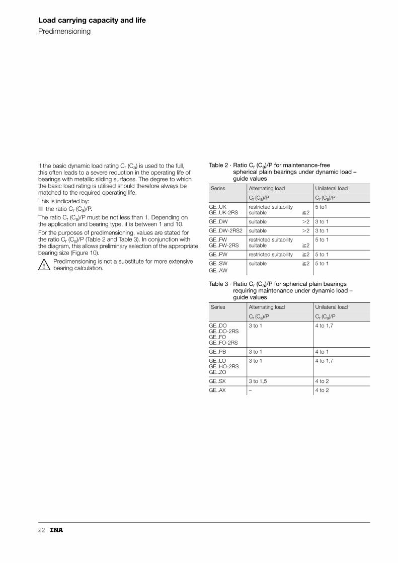
If the basic dynamic load rating Cr (Ca) is used to the full, this often leads to a severe reduction in the operating life of bearings with metallic sliding surfaces. The degree to which the basic load rating is utilised should therefore always be matched to the required operating life.This is indicated by:■ the ratio Cr (Ca)/P.The ratio Cr (Ca)/P must be not less than 1. Depending on the application and bearing type, it is between 1 and 10.For the purposes of predimensioning, values are stated for the ratio Cr (Ca)/P (Table 2 and Table 3). In conjunction with the diagram, this allows preliminary selection of the appropriate bearing size (Figure 10).
Predimensioning is not a substitute for more extensive bearing calculation.
Table 2 · Ratio Cr (Ca)/P for maintenance-free spherical plain bearings under dynamic load – guide values
Series Alternating load Unilateral load
Cr (Ca)/P Cr (Ca)/P
GE..UKGE..UK-2RS
restricted suitabilitysuitable �2
5 to1
GE..DW suitable �2 3 to 1
GE..DW-2RS2 suitable �2 3 to 1
GE..FWGE..FW-2RS
restricted suitabilitysuitable �2
5 to 1
GE..PW restricted suitability �2 5 to 1
GE..SWGE..AW
suitable �2 5 to 1
Table 3 · Ratio Cr (Ca)/P for spherical plain bearings requiring maintenance under dynamic load – guide values
Series Alternating load Unilateral load
Cr (Ca)/P Cr (Ca)/P
GE..DOGE..DO-2RSGE..FOGE..FO-2RS
3 to 1 4 to 1,7
GE..PB 3 to 1 4 to 1
GE..LOGE..HO-2RSGE..ZO
3 to 1 4 to 1,7
GE..SX 3 to 1,5 4 to 2
GE..AX – 4 to 2

23
Figure 10 · Bearing size, load and ratio Cr (Ca)/P for predimensioning
GE
..S
XG
E..
AX
GE
..P
BG
E..
PW
GE
..Z
OG
E..
LO
G
E..FO
G
E..D
OG
E..
HO
-2R
S
GE
..FW
-2R
SG
E..
UK
-2R
S
GE
..FW
GE
..U
K
GE
..S
WG
E..
AW
200190180170
160150140130120110
10090
8070656055
50454035302825
200180160140
120100
7060
45
40
35
30
25
6
25 30
20 25
17 20
15 17
12 15
10 12
8 10
86
10
8
6
5
12
14
1618
20
22
25
30
6
5
8
10
12
14
16
182022
25
30
19
22
25
313438
44
50
57
6369
76
12
16
20
25
32
40
50
63
70
80
90
100110
125
160
200
250
6
8
10
12
15
17
10
1517
20
25
30
35
40
45
50
60
70
80
90100
110
280260240220200180
160
120
140
8
10
12
15
17
20
25
30
35
40
45
50
60
70
80
90
100110
120
300280260240220200
180
140
160
6
1)
1)
1)
30
35
40
45
50
60
70
80
90100
110120
140160
180200220240260280 300
280260240220200
180160
140120
110100
90
80
70
60
50
45
40
35
30
25
20
17
3028
25
35404550
55606570
12
10
1517
20
25
30
35
40
45
506070
80100120
140160180200
80
90100
110120
130140150160
170180190200
mm
1 5 10 50 100 500 1000 5.00010.000
kN 20.00040.000
20
50
C ,
(C )
/P =
10
ra
C ,
(C )
/P =
5
ra
C ,
(C )
/P =
3
ra
C ,
(C )
/P =
2
ra
C ,
(C )
/P =
1
ra
Bearing load
Nom
inal
siz
e
= also valid for 2RS design
151
171

24
Load carrying capacity and life
Bearing motionRating life
Spherical plain bearings are principally intended to support high loads under oscillating motion.The term “bearing motion” describes the dynamic conditions in the bearing.These are essentially characterised by:■ the magnitude of the motion■ the speed of the motion■ the frequency of the motion.
Motion parameter – swivel angle and tilt angleSwivel motion is defined as the oscillating motion of the two bearing rings in relation to each other about the axis of the bearing.
Swivel angleThe centring angle described by the two extreme points of the motion is defined as the swivel angle � (Figure 11). This describes the motion between the two extreme points.
Tilt angleIn tilting motion, the inner ring or shaft locating washer moves relative to the outer ring or housing locating washer in a direction transverse to the bearing axis. The axes of the relevant bearing rings intersect at the tilt angle � (Figure 12).The permissible tilt angle � is given in the dimension tables, based on full utilisation of the basic load ratings.
Combined swivel and tilt motionThe motion angle �1 corresponding to the sliding distance can be calculated for linear and ellipsoid motion (Figure 13).Linear motion:
Ellipsoid motion:
�1 °Motion angle corresponding to sliding distance
�1 °Tilt angle – from centre to left
�2 °Tilt angle – from centre to right.
Figure 11 · Swivel motion – swivel angle �
Figure 12 · Tilt motion – tilt angle �
Figure 13 · Swivel and tilt motion – motion angle �1
�1 �2 + �1 + �2( )22=
�1 � �1 + �2( ) + � – �1 – �2( )2⋅ ⋅
� + �1 + �2----------------------------------------------------------------------------------------=
�
117
101
�1
2�
117
102
117
103
25
Rotary motionThe sliding distance covered in a motion cycle – motion from the start point to the return point and back – corresponds to twice the arc length of the angle � or �. For this reason, an angle � = 180° should be used for rotary motion in life calculation.
Frequency of motionThe number of motions per time period – the frequency – has a significant influence on the life of spherical plain bearings and cylindrical plain bushes.The frictional energy generated in the bearing is influenced by the frequency of motion as well as the load, coefficient of friction and the magnitude of the motion. It is dependent on the relevant sliding contact surface and must not exceed the permissible p · v values.
The frequency can only be used for calculating the mean sliding speed in applications with continuous operation or periodic stationary periods.
Intermittent operationIn this case, the mean sliding speed during one motion cycle must be used.
LifeCalculation of the theoretical life is based on a large number of laboratory tests and assumes certain operational data:■ lithium soap multi-purpose greases with solid additives are
used in spherical plain bearings with a steel/steel sliding contact surface.
The life is defined as the number of swivel motions or operating hours that can be achieved by a sufficiently large number of spherical plain bearings or cylindrical plain bushes under identical operating conditions before certain failure criteria are met. The failure criteria are defined by the manufacturer as test limit values related to:■ an amount of wear dependent on the bearing size
or■ an upper friction limit which is exceeded.The amount of wear and increase in friction are dependent on the sliding contact surface and the application. Under identical operating conditions, the operating life achieved may therefore differ significantly.
Calculation of the theoretical life gives comparative values for the bearings. They can be used to assess the greater or lesser performance of the bearings selected. Life calculation:■ Maintenance-free spherical plain bearings
(page 63 to 71)■ Maintenance-free cylindrical plain bushes
(page 72, 73)■ Maintenance-free rod ends
(page 63 to 71 and 128, 129)■ Spherical plain bearings requiring maintenance
(page 97 to 99)■ Rod ends requiring maintenance
(page 97 to 99 and 146 to 148).
Operating lifeThe operating life is the number of motion cycles or operating hours achieved in practice by a spherical plain bearing or a cylindrical plain bush. It may differ from the calculated theoretical life.The operating life is dependent on factors including:■ the type and magnitude of load■ any shocks occurring■ the sealing arrangement■ corrosion■ contamination■ maintenance.
Calculation serviceThe influences that must be taken into consideration in calculation are expressed as mathematical functions. As a result, the calculation principles can be programmed, eliminating the need for time-consuming manual calculation work.Calculation programs are available which may be used on request.
The theoretical life calculations are valid for the products described in this catalogue.Under no circumstances can they be transferred to other products.

26
Friction
Friction is principally dependent on:■ the sliding contact surface■ the load■ the sliding speed■ the bearing temperature■ the lubrication condition■ the quality of the sliding surfaces.
Friction behaviour of spherical plain bearings requiring maintenance, maintenance-free spherical plain bearings and maintenance-free cylindrical plain bushesThe friction behaviour changes during the operating life.The lowest friction values are found with bearings that are well run in. The values are significantly higher during the running-in and failure phases.
For safety reasons, the maximum values should always be used for calculating the drive power (Table 1).
If the friction value exceeds the maximum value, this may have the following consequences:■ wear may increase■ the bearing temperature may rise■ the function of the bearing may be impaired.
Bearing frictional torqueThe bearing frictional torque M (from the formula) is valid for (Figure 1):■ radial and angular contact spherical plain bearings under
radial load■ axial spherical plain bearings under axial load.
If the bearing is subjected to combined load (radial and axial), the bearing frictional torque is calculated by integration of the standard loads.
M NmBearing frictional torque
P NEquivalent dynamic bearing load
� –Friction factor (Table 1)
dK mmSphere diameter of spherical plain bearing (dimension table).For maintenance-free cylindrical plain bushes, use d instead of dK = d (see dimension table).
Figure 1 · Load on spherical plain bearing
M P � dK 0,0005⋅ ⋅ ⋅=
0,0005 takes account of Sphere radiusSphere diameter------------------------------------------ 1 m
1000 mm-------------------------⋅
Table 1 · Friction factor � for spherical plain bearings and plain bushes
Sliding contact surface Friction factor�
min. max.
Steel/steel 0,08 0,22
Steel/bronze 0,1 0,25
Hard chromium/PTFE composite 0,05 0,2
Steel/PTFE-bronze film 0,05 0,2
Hard chromium/ELGOGLIDE® 0,02 0,2
117
104
27
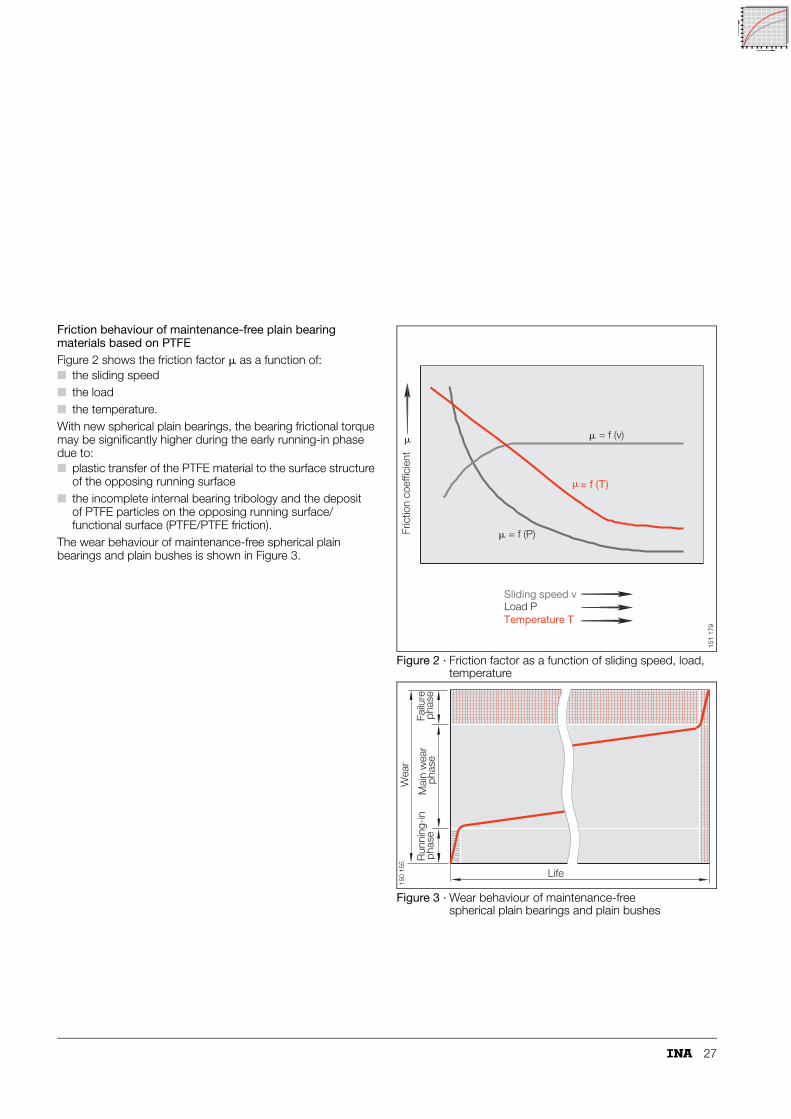
Friction behaviour of maintenance-free plain bearing materials based on PTFEFigure 2 shows the friction factor � as a function of:■ the sliding speed■ the load■ the temperature.With new spherical plain bearings, the bearing frictional torque may be significantly higher during the early running-in phase due to:■ plastic transfer of the PTFE material to the surface structure
of the opposing running surface■ the incomplete internal bearing tribology and the deposit
of PTFE particles on the opposing running surface/functional surface (PTFE/PTFE friction).
The wear behaviour of maintenance-free spherical plain bearings and plain bushes is shown in Figure 3.
Figure 2 · Friction factor as a function of sliding speed, load, temperature
Figure 3 · Wear behaviour of maintenance-free spherical plain bearings and plain bushes
� = f (v)
= f (T)�
� = f (P)
�
Load P Sliding speed v
Temperature T
Fric
tion
coef
ficie
nt
151
179
Life
Run
ning
-inph
ase
Failu
reph
ase
Wea
r
phas
eM
ain
wea
r
150
155
28
Lubrication
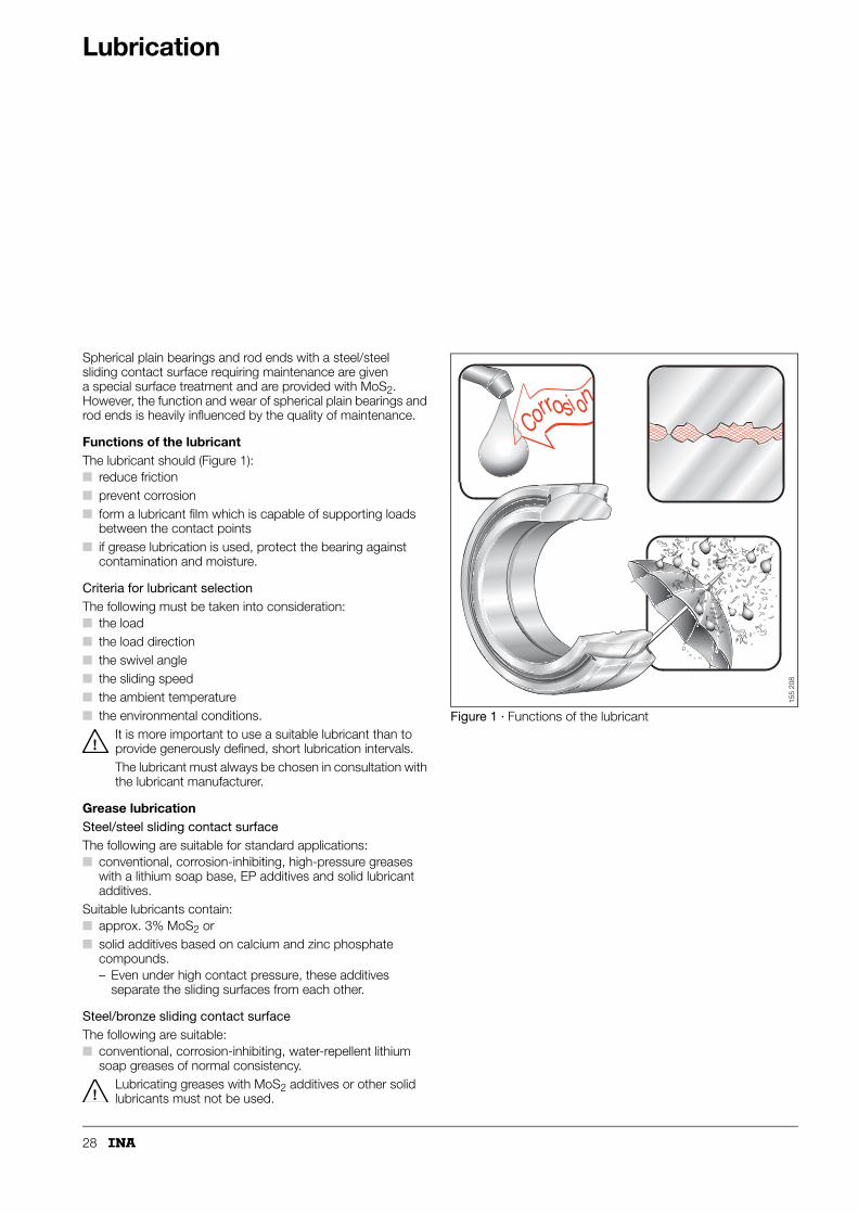
Spherical plain bearings and rod ends with a steel/steel sliding contact surface requiring maintenance are given a special surface treatment and are provided with MoS2. However, the function and wear of spherical plain bearings and rod ends is heavily influenced by the quality of maintenance.
Functions of the lubricantThe lubricant should (Figure 1):■ reduce friction■ prevent corrosion■ form a lubricant film which is capable of supporting loads
between the contact points■ if grease lubrication is used, protect the bearing against
contamination and moisture.
Criteria for lubricant selectionThe following must be taken into consideration:■ the load■ the load direction■ the swivel angle■ the sliding speed■ the ambient temperature■ the environmental conditions.
It is more important to use a suitable lubricant than to provide generously defined, short lubrication intervals.The lubricant must always be chosen in consultation with the lubricant manufacturer.
Grease lubricationSteel/steel sliding contact surfaceThe following are suitable for standard applications:■ conventional, corrosion-inhibiting, high-pressure greases
with a lithium soap base, EP additives and solid lubricant additives.
Suitable lubricants contain:■ approx. 3% MoS2 or■ solid additives based on calcium and zinc phosphate
compounds.– Even under high contact pressure, these additives
separate the sliding surfaces from each other.
Steel/bronze sliding contact surfaceThe following are suitable:■ conventional, corrosion-inhibiting, water-repellent lithium
soap greases of normal consistency.Lubricating greases with MoS2 additives or other solid lubricants must not be used.
Figure 1 · Functions of the lubricant
Cor i onro s
155
208

29
Running-in phaseThe running-in phase has a significant influence on the later wear behaviour of the bearing. Correct lubrication is of particular importance at this point.During running-in■ the surfaces of the contact zones are smoothed■ the contact zones are elastically bedded in.This increases the contact area and reduces the load on the material.
GreasingDuring the running-in phase, the pressure in the bearing is particularly high. Spherical plain bearings are therefore manganese phosphated and treated with MoS2.The wear occurring during the running-in phase proceeds all the more favourably the more MoS2 is embedded in the porous-crystalline manganese phosphate. This process is at its most effective if the bearing:■ is subjected to about ten swivel motions under load without
additional greasing■ is then provided with an initial greasing.If this is not possible, the initial greasing must be metered carefully in order to avoid flushing an excessive quantity of MoS2 out of the bearing.
RelubricationDuring relubrication, old grease is replaced by fresh grease. At the same time, the grease flushes wear debris and contaminants out of the bearing.
Bearings with steel/steel sliding contact surfaces must be periodically relubricated.The relubrication intervals should not be established arbitrarily but determined by calculation or in consultation with the lubricant manufacturer.If relubrication is carried out too frequently, the operating life of the bearing may be reduced, since the friction of spherical plain bearings always increases for a short time after relubrication.
Preconditions■ the grease should be the same as that used for initial
greasing– if different greases are used, their miscibility and
compatibility should be checked■ relubrication should be carried out
– with the bearing still warm from operation– before the bearing comes to rest if safe to do so– before extended breaks in operation.
Maintenance-free spherical plain bearings, plain bushes and rod endsDuring the running-in phase, PTFE particles are transferred from the outer ring sliding layer to the opposing running surface of the inner ring. This fills in the areas of slight roughness in the inner ring surface. A long operating life is only achieved with this tribologically smooth surface.
Maintenance-free spherical plain bearings, plain bushes and rod ends must not be relubricated. The PTFE particles to be transferred do not adhere to oily surfaces. Lubricant therefore prevents the necessary smoothing of the surface.If spherical plain bearings, plain bushes and rod ends that have been subjected to dry running-in are subsequently lubricated, this damages the smoothing effect previously achieved.
Maintenance-free spherical plain bearings, plain bushes and rods ends do not have any facilities for relubrication.

30
Internal clearance and operating clearanceInternal clearance
Radial internal clearanceRadial internal clearance of radial spherical plain bearings requiring maintenance with steel/steel sliding contact surfaceThe radial internal clearance is defined as the distance by which the inner ring can be moved in a radial direction relative to the outer ring from one extreme position to the other (Figure 1).The radial internal clearance is divided into three groups (Table 1 and Table 2) and is given in the dimension tables. This assumes that the bearing is mounted in a housing bore that, apart from the correction of geometrical inaccuracies, causes no dimensional changes in the bearing.
Normal internal clearanceThe normal internal clearance gives an optimum operating clearance under normal operating conditions if the recommended fits (see Design of bearing arrangements, Seite 37) are used.
Radial internal clearance larger or smaller than normalIn order to meet the requirements arising from different operating or installation conditions, the bearings are also available with (Table 1 and Table 2):■ internal clearance larger than normal
– where tight fits are used or there are large temperature differences between the inner and outer ring
■ internal clearance smaller than normal– for bearing arrangements with very small clearance.
SuffixesSpherical plain bearings with normal internal clearance do not have a suffix.Bearings with a radial internal clearance C2 and C3 differ from the standard design. They are ordered using a suffix.
Example
Spherical plain bearing GE 60 DO with reduced internal clearance: GE 60 DO-C2.
Axial internal clearanceThe axial internal clearance is defined as the amount by which the inner ring can be moved in an axial direction relative to the outer ring from one extreme position to the other (Figure 2).It is dependent on the bearing geometry and is in a direct relationship to the radial internal clearance. Depending on the bearing type, it may be several times greater than the radial internal clearance.
Figure 1 · Radial internal clearance
Figure 2 · Axial internal clearance
1) Relubrication only possible with tilt angle � = 0°.
Table 1 · Radial internal clearance groups
Group
C21) CN C3
smaller than normal normal larger than normal
Radial internal
clearanceRadial internal
clearanceRadial internal
clearance
117
116
Axial internal
clearanceAxial internal
clearanceAxial internal
clearance11
7 11
7

31
For further internal clearance values see dimension tables.
Table 2 · Radial internal clearance groups
Series Radial internal clearance in �m
GE..DOGE..DO-2RSGE..HO-2RSGE..LO
GE..FOGE..FO-2RS
C2 CN C3
Bored
Bored
mm mm min. max. min. max. min. max.
6 6 8 32 32 68 68 104
8 8 8 32 32 68 68 104
10 10 8 32 32 68 68 104
12 – 8 32 32 68 68 104
– 12 10 40 40 82 82 124
15 15 10 40 40 82 82 124
16 – 10 40 40 82 82 124
17 17 10 40 40 82 82 124
20 – 10 40 40 82 82 124
– 20 12 50 50 100 100 150
25 25 12 50 50 100 100 150
30 30 12 50 50 100 100 150
32 – 12 50 50 100 100 150
35 – 12 50 50 100 100 150
– 35 15 60 60 120 120 150
40 40 15 60 60 120 120 180
45 45 15 60 60 120 120 180
50 50 15 60 60 120 120 180
60 – 15 60 60 120 120 180
– 60 18 72 72 142 142 212
(continued)
Series Radial internal clearance in �m
GE..DOGE..DO-2RSGE..HO-2RSGE..LO
GE..FOGE..FO-2RS
C2 CN C3
Bored
Bored
mm mm min. max. min. max. min. max.
63 – 18 72 72 142 142 212
70 70 18 72 72 142 142 212
80 80 18 72 72 142 142 212
90 – 18 72 72 142 142 212
– 90 18 85 85 165 165 245
100 100 18 85 85 165 165 245
110 110 18 85 85 165 165 245
120 120 18 85 85 165 165 245
140 – 18 85 85 165 165 245
160 140 18 100 100 192 192 284
180 160 18 100 100 192 192 284
200 180 18 100 100 192 192 284
– 200 18 110 110 214 214 318
220 220 18 110 110 214 214 318
240 – 18 110 110 214 214 318
250 240 18 125 125 239 239 353
260 260 18 125 125 239 239 353
280 280 18 125 125 239 239 353
300 – 18 125 125 239 239 353

32
Internal clearance and operating clearance
Internal clearance
Internal clearance of cylindrical plain bushesBearings requiring maintenance must have a minimum radial internal clearance for lubrication. Maintenance-free cylindrical plain bushes have an integral solid lubricant supply. They do not therefore require this minimum radial clearance for lubrication purposes.Fitting without clearance has particular advantages, especially with alternating load directions. Load distribution is also improved, especially during running-in, due to the larger load-bearing areas.In order to achieve the largest possible load-bearing angle, the operating clearance S must not exceed defined limits. The clearance can be expressed as a function of the relative internal clearance � (Figure 3 and formula).For bore diameters d = 30 mm to 200 mm, guide values are given in Table 3.These ranges can be used:■ due to the standard tolerances of the plain bushes and■ if the housing bore and shaft are manufactured to
the “average tolerance”.
S �mOperating clearance
� ‰Relative internal clearance in fitted condition
d mmShaft diameter or bore diameter of inner ring.
Figure 3 · Internal clearance of cylindrical plain bushes
S � d⋅=
Table 3 · Bore diameter and relative internal clearance � in fitted condition – guide values
Bore diametermm
d 80 d �80 to 120 d � 120 to 200
� � 1‰ � � 0,75‰ � � 0,5‰
S
117
131

33
Fits related to practical use for spherical plain bearingsTables 4 and 5 show the tolerances and clearances which result from the corresponding ISO fits in conjunction with normal bearing tolerances to ISO 12 240-1 to -3 when the actual dimensions correspond to “average tolerance”:■ – indicates interference■ + indicates clearance.
1) Example: shaft, diameter 50 m6;probable interference 0,023 mm.
2) Not applicable to series GE..LO, GE..PB, GE..SX, GE..PW, GE..SW.
1) Example: Housing bore, diameter 75 M7;probable interference 0,009 mm.
2) Not applicable to series GE..SX, GE..SW.
Table 4 · Fits for shafts – interference Ül in �m1)2)
Bearing inner ring/shaft
Nominal deviation range in �m
Desig-nation
overincl.
36
610
1018
1830
3050
5080
80120
120180
180250
250315
315400
400500
h6 0 0 +1 +1 +2 +2 +1 0 0 –2 –2 –2
j6 –6 –7 –7 –8 –9 –10 –13 –14 –17 –17 –20 –22
k6 –9 –9 –9 –14 –16 –20 –24 –28 –30 –33 –38 –42
m6 –12 –15 –17 –20 –23 –28 –34 –40 –47 –53 –59 –65
n6 –16 –19 –22 –27 –31 –37 –44 –52 –61 –67 –75 –82
Table 5 · Fits for housing bores – interference ÜA or clearance in �m1)2)
Bearing outer ring/housing
Nominal deviation range in �m
Desig-nation
overincl.
610
1018
1830
3050
5080
80120
120150
150180
180250
250315
315400
400500
J7 +4 +5 +6 +7 +10 +12 +15 +18 +22 +27 +31 +34
K7 +1 +1 –1 0 0 –1 +1 +4 +5 +7 +8 +8
M7 –4 –5 –7 –8 –9 –11 –11 –8 –8 –9 –9 –10
N7 –8 –10 –14 –16 –18 –21 –23 –20 –22 –23 –25 –27
J7 +4 +5 +6 +7 +10 +12 +15 +18 +22 +27 +31 +34

34
Internal clearance and operating clearance
Operating clearance
The operating clearance is determined on a fitted bearing still warm from operation.It is calculated from:■ the radial internal clearance (Table 2, page 31)■ the change in the radial internal clearance due to
interference and temperature influences in a fitted bearing.
Influence of interference on the radial internal clearance of radial spherical plain bearingsThe radial internal clearance changes due to the fit as a result of:■ expansion of the inner ring■ contraction of the outer ring.
Expansion of the inner ring
a �mExpansion of inner ring when using solid shafts – measured on sphere diameter
b –Factor for the cross-section of the inner ring (Table 6, Figure 4)
ÜI �mEffective interference (Table 4, page 33)
0,9 –Factor for the roughness, ovality and unevenness of the supporting component surface.
Contraction of the outer ringWith ring-shaped housings, expansion of the housing must be taken into consideration. The expansion is dependent on the wall thickness and is included in calculation using the factor f.
e �mContraction of the outer ring –measured on the sphere diameter
c –Factor for the cross-section of the outer ring (Table 7, Figure 4)
f –Factor for the expansion of the housing (Figure 5)
ÜA �mEffective interference (Table 5, page 33)
0,9 –Factor for the roughness, ovality and unevenness of the supporting component surface.
Figure 4 · Factor b and factor c
1) Dimension Ül is not listed in Table 4.
a ÜI b 0,9⋅ ⋅=
e ÜA f 0,9⋅ ⋅=
Table 6 · Factor for the cross-section of the inner ring
Bore Series
dmm
over
dmm
incl.
GE..DO/GE..DO-2RSGE..HO-2RSGE..LO1)
GE..UKGE..UK-2RSb
GE..FO/GE..FO-2RSGE..FW/GE..FW-2RSGE..PB1)
GE..PW1)
b
6 10 0,65 0,55
12 20 0,72 0,64
25 70 0,79 0,71
80 140 0,80 0,75
160 300 0,84 0,78
Table 7 · Factor c for the cross-section of the outer ring
Bore Series
dmm
over
dmm
incl.
GE..DO/GE..DO-2RSGE..HO-2RSGE..LOGE..UKGE..UK-2RSc
GE..FO/GE..FO-2RSGE..FW/GE..FW-2RSGE..PBGE..PW
c
6 – 0,7 –
6 20 – 0,81
8 25 0,81 –
25 35 – 0,83
30 40 0,83 –
40 280 – 0,85
45 300 0,85 –
b
c
f
117
094
35
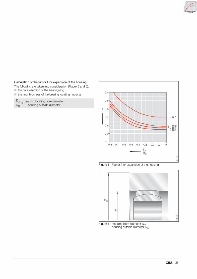
Calculation of the factor f for expansion of the housingThe following are taken into consideration (Figure 5 and 6):■ the cross-section of the bearing ring■ the ring thickness of the bearing locating housing.
Figure 5 · Factor f for expansion of the housing
Figure 6 · Housing bore diameter DA/housing outside diameter DG
DA
DG------- bearing locating bore diameter
housing outside diameter------------------------------------------------------------------------------=
f
0,8 0,7 0,6 0,5 0,4 0,3 0,2 0,1 0
0,4
0,5
0,6
0,7
0,8
0,9
1
DADG
c = 0,81c = 0,83c = 0,85
c = 0,7
151
192
DG
DA
117
095
36
Internal clearance and operating clearance
Operating clearance
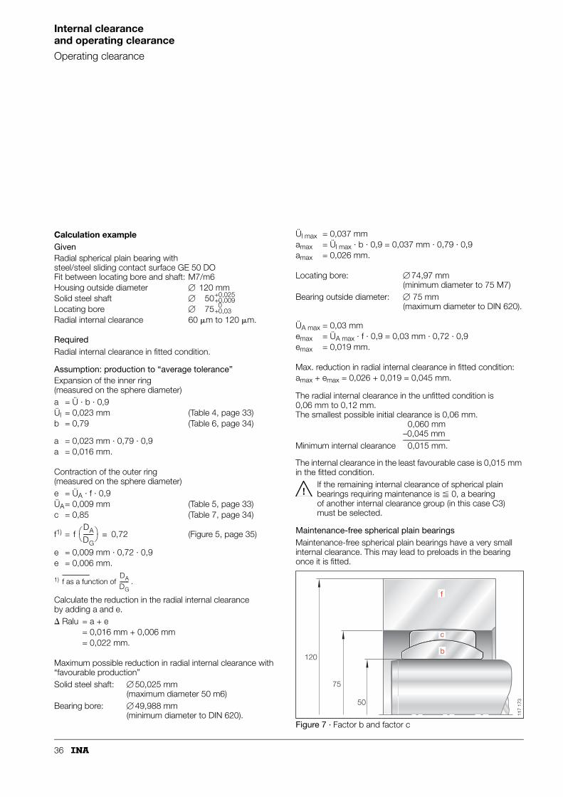
Calculation exampleGiven
RequiredRadial internal clearance in fitted condition.
Assumption: production to “average tolerance”
The internal clearance in the least favourable case is 0,015 mm in the fitted condition.
If the remaining internal clearance of spherical plain bearings requiring maintenance is � 0, a bearing of another internal clearance group (in this case C3) must be selected.
Maintenance-free spherical plain bearingsMaintenance-free spherical plain bearings have a very small internal clearance. This may lead to preloads in the bearing once it is fitted.
Figure 7 · Factor b and factor c
Radial spherical plain bearing with steel/steel sliding contact surface GE 50 DOFit between locating bore and shaft: M7/m6Housing outside diameter � 120 mmSolid steel shaft �
Locating bore �
Radial internal clearance 60 �m to 120 �m.
Expansion of the inner ring(measured on the sphere diameter)a = Ü · b · 0,9Ül = 0,023 mm (Table 4, page 33)b = 0,79 (Table 6, page 34)
a = 0,023 mm · 0,79 · 0,9a = 0,016 mm.
Contraction of the outer ring(measured on the sphere diameter)e = ÜA · f · 0,9ÜA= 0,009 mm (Table 5, page 33)c = 0,85 (Table 7, page 34)
f1) = (Figure 5, page 35)
e = 0,009 mm · 0,72 · 0,9e = 0,006 mm.
1) f as a function of .
Calculate the reduction in the radial internal clearance by adding a and e. Ralu = a + e
= 0,016 mm + 0,006 mm= 0,022 mm.
Maximum possible reduction in radial internal clearance with “favourable production”Solid steel shaft: � 50,025 mm
(maximum diameter 50 m6)Bearing bore: � 49,988 mm
(minimum diameter to DIN 620).
50+0,025+0,009
75 0+0,03
f DA
DG-------⎝ ⎠⎛ ⎞ 0,72=
DA
DG-------
Ül max = 0,037 mmamax = Ül max · b · 0,9 = 0,037 mm · 0,79 · 0,9amax = 0,026 mm.
Locating bore: � 74,97 mm(minimum diameter to 75 M7)
Bearing outside diameter: � 75 mm(maximum diameter to DIN 620).
ÜA max = 0,03 mmemax = ÜA max · f · 0,9 = 0,03 mm · 0,72 · 0,9emax = 0,019 mm.
Max. reduction in radial internal clearance in fitted condition:amax + emax = 0,026 + 0,019 = 0,045 mm.
The radial internal clearance in the unfitted condition is 0,06 mm to 0,12 mm. The smallest possible initial clearance is 0,06 mm.
0,060 mm–0,045 mm
Minimum internal clearance 0,015 mm.
b
c
50
75
120
f
117
173

37
Design of bearing arrangementsRadial location of spherical plain bearings and maintenance-free cylindrical plain bushes
In spherical plain bearings, sliding motion should occur between the spherical sliding surfaces of the inner and outer rings – the quality and treatment of the surfaces are matched to this purpose. The internal clearance and osculation of the sliding surfaces must therefore be in a balanced relationship.
Spherical plain bearings requiring maintenanceThe operating life of spherical plain bearings requiring maintenance is reduced by:■ preload on the sliding surfaces■ excessively small load-bearing areas on the sliding surfaces
due to unacceptably large internal clearance.The recommended fits are given in Table 1).
If tighter fits are required, for example due to high impact-type loads, the operating clearance must be checked by calculation (see Influence of interference on the radial internal clearance, page 34).
Maintenance-free spherical plain bearingsLooser fits may be used with maintenance-free bearings:■ due to the hard chromium/PTFE sliding contact surface,
friction is lower than with steel/steel sliding contact surfaces.The recommended fits are given in Table 2.
Application as locating bearingsThe shaft and bore fits must be selected such that no sliding motion occurs on the shaft or in the bore.■ Tight fits prevent damage to the adjacent construction.When using tight fits, however, it must be noted that:■ interference between the housing and outer ring
causes contraction of the outer ring■ interference between the shaft and bearing bore
causes expansion of the inner ring.These elastic deformations of the bearing rings reduce the internal clearance of the bearing (see Influence of interference on the radial internal clearance, page 34).If a tight fit is not possible, the bearing rings must be secured against axial sliding motion on the shaft or in the housing (Axial location, page 38).
Application as non-locating bearings (between shaft and bearing bore)The surface of the shaft must be wear-resistant as follows:■ surface hardness � 56 HRC■ maximum surface roughness Rz10.Spherical plain bearings requiring maintenance should then only be lubricated via the shaft. Maintenance-free spherical plain bearings can have a lining of sliding material ELGOGLIDE®
in the inner ring bore, suffix W7, W8 (page 13).
1) GE..LO: for shaft r6.2) GE..PB: housing/shaft K7/m6.
1) GE..PW: for shaft m6.
Table 1 · Shaft and housing fits for spherical plain bearings requiring maintenance
Spherical plain bearings requiring maintenance
Internal clearance
Material
Housing/shaft Housing/shaft
Group Steel/steel Light metal/steel
Radial spherical plain bearings
C2 K7/j61) M7/j61)
Radial spherical plain bearings
CN(normal)
M7/m61)2) N7/m61)2)
Radial spherical plain bearings
C3 M7/m61) N7/m61)
Angular contact spherical plain bearings
– M7/n6 –
Axial spherical plain bearings
– M7/n6 –
Table 2 · Shaft and housing fits for maintenance-free spherical plain bearings and maintenance-free cylindrical plain bushes
Maintenance-free spherical plain bearings/maintenance-free cylindrical plain bushes
Bored
Material
Housing/shaft Housing/shaft
mm Steel/steel Light metal/steel
Radial spherical plain bearings
up to 300 K7/j61) M7/j61)
Radial spherical plain bearings
over 300 J7/j6 –
Angular contact spherical plain bearings
– M7/m6 –
Axial spherical plain bearings
– M7/m6 –
Maintenance-free cylindrical plain bushes
– H7/f7 –

38
Design of bearing arrangements
Axial location of spherical plain bearings
Spherical plain bearings under high load undergo elastic deformation. This leads to relative micromovements on the seating surfaces. As a result, the bearing rings can creep in an axial direction despite a tight fit.
In order to prevent axial displacement, the bearing ring must always be located axially.
Non-locating bearing sideThe axial displacement should occur between the shaft and bearing bore because:■ the length/diameter ratio of the guidance is more favourable
at this point than on the outer ring of the bearing■ the axially split outer ring expands under axial load and
can therefore jam in the bearing location■ no wear should in general occur in the housing bore.
Location of bearing ringsThe following are suitable for location (Figure 1, 2 and 3):■ retaining rings
– the bearings can thus be easily fitted and dismantled■ spacers between the bearing ring and adjacent construction
if:– the shaft must not be weakened by the use of annular
grooves– the bearings are to be axially preloaded – this prevents
rotary motion between the bearing ring and adjacent construction even with a loose fit.
Figure 1 · Location by snap rings
Figure 2 · Location by snap rings and spacers
Figure 3 · Location by snap rings and spacers
117
119
117
118
117
191

39
Design of bearing arrangements
Design of adjacent components
Chamfer dimensionsSpherical plain bearings have a convex transition between the outside surface and bore to the end faces. This makes fitting of the bearing easier.The bearing rings must be in contact with the shaft and housing shoulders. The largest radius of the shaft/housing locating face must therefore not be larger than the smallest chamfer dimension r1s/r2s of the spherical plain bearing (Figure 4 and dimension table).
Quality of shaft and housing boreThe seating surfaces of the bearing should be such that the loads transmitted through the bearing:■ do not cause unacceptable geometrical deviations of
the shaft and housing■ do not cause permanent deformation of the spherical plain
bearing.In the case of highly loaded spherical plain bearings with p � 80 N/mm2, the shaft and housing must be checked.
The geometrical accuracy of the seating surfaces should be within the tolerance ranges of the recommended fit.The recommended surface quality values are given in Table 3 and 4. If larger roughness values are present, please consult INA.
Figure 4 · Chamfer dimensions
1) Recommended: Rz � 1,6. Note the guidelines on page 62, page 72 and in Figure 13.
Table 3 · Roughness values for the bearing seating surface – spherical plain bearings and rod ends
Roughness�m
Bearing seat
� Rz16 Housing bore
� Rz10 shaft
Table 4 · Roughness values for the bearing seating surface – maintenance-free cylindrical plain bushes
Roughness�m
Bearing seat
� Rz10 Housing bore
Rz1 to Rz41) shaft
r
r
r
s min
s
s max
r s m
ax
r s
r s m
in
axial
radi
al
117
121

40
Sealing
In selection (Table 1), account must be taken of: ■ the operating and environmental conditions■ the rotary motion of the bearing■ the tilt angle of the bearing■ the available space■ the costs and work required.
Table 1 · Seals
Seal type Features Application
Grease collar ■ Simple and effective sealing■ Due to frequent relubrication,
a grease collar is formed on the end faces of the spherical plain bearing
■ Bearings requiring maintenance■ Proven for aggressive operating
conditions in conjunction with daily maintenance
■ Temperature usage according to grease selection
2RS seal ■ Polyurethane lip seal■ Radially preloaded seal lips
■ Higher demands for sealing action■ Favourable for indoor applications■ Operating temperatures
from –30 °C to +130 °C
2RS1 seal ■ Lip seal with outer sealing shield■ Radially preloaded seal lips■ Special design.
Only available by agreement
■ For very high requirements and long maintenance intervals
■ Protection against coarse and very fine contaminants
■ Operating temperatures from –40 °C to +200 °C
2RS2 seal ■ On both sides with increased sealing action
■ Large radial spherical plain bearings
■ For very high requirements and long maintenance intervals
■ Protection against coarse and very fine contaminants
■ Operating temperatures from –40 °C to +120 °C
External seal ■ Simple but very effective seal■ Partially cellular polyurethane
elastomer sealing rings■ Standard seal from individual
sealing ring manufacturers
■ Specially developed for radial spherical plain bearings to ISO 12 240-1, dimensions series E
■ Suitable for integration in adjacent construction as external seal
■ Lower seal friction if sealing rings are worked in oil or flowable grease before assembly
■ Operating temperatures from –40 °C to +100 °C
117
122
117
123
117
124
117
216
117
125

41
Maintenance-free cylindrical plain bushesSuitable seals are shown in Table 1.During the operating life, the operating clearance may increase – under high alternating loads, this may be by 0,5 mm to 0,8 mm. Furthermore, the plain bushes are not relubricated.
These points must be taken into consideration in the design of the seal and seal environment – the suitability of the seal must be agreed with the seal manufacturer.
Seals (continued)
Seal type Features Application
V ring seal ■ Solid rubber body on shaft■ Single seal lip, axially preloaded■ Resistant to grease, oil and ageing
■ Suitable for relatively large tilting motions
■ Particularly user-friendly■ Operating temperatures
from –40 °C to +100 °C
V ring seal ■ Seal lips on both sides■ Inside diameter of ring in contact
with spherical surface of inner ring
■ Simple sealing■ Operating temperatures
from –40 °C to +100 °C
Two component seal
■ Seal lip made from PTFE/modified nitrile mixture, preloaded by alloy steel coil spring
■ Seal shoulder with cotton-reinforced nitrile mixture
■ Seal on projecting part of inner ring spherical surface
■ Easy handling■ Operating temperatures
from –40 °C to +120 °C, up to +150 °C for short periods
Rotary shaft seals
■ Proven standard rotary shaft seal■ Plastic ring with seal lip and
steel reinforcement■ Seal lip preloaded by coil spring
■ For small tilt angles with grease and oil lubrication
■ Grease lubrication: seal lip facing outwards
■ Oil bath lubrication: seal lip facing inwards
■ Oil bath lubrication: rotary shaft seal with additional dust lip facing outwards
■ Temperature usage dependent on the seal material
117
126
117
127
117
128
117
129
42
Fitting and dismantlingFitting
Spherical plain bearings, rod ends and cylindrical plain bushes are high precision machine elements. They must be handled very carefully both before and during fitting. Problem-free functioning is substantially dependent on the care taken in fitting.Bearing failures will lead to:■ machine downtime■ expensive repairs.
If bearings are fitted incorrectly, no liability can be accepted.
Spherical plain bearings, rod ends and cylindrical plain bushes should only be fitted by personnel with sufficient and appropriate training. In case of doubt, please consult INA.
Delivered conditionSpherical plain bearings and cylindrical plain bushes are supplied with the surfaces (except the bore) protected by a preservative. Depending on their design, rod ends are supplied protected by a preservative or with a zinc plating.
Any change, irrespective of the bearing type, will reduce the operating life of the bearing.Bearings must not be treated or cleaned using trichloroethylene, perchloroethylene, petroleum spirit or other solvents.Substances containing oil will change the characteristics of the bearing.
StorageBearings should only be stored: ■ in the original packaging■ in dry, clean rooms with the temperature as constant
as possible■ at a relative humidity of max. 65%.
Removal from packagingPerspiration from handling leads to corrosion. Hands should be kept clean and dry and gloves worn if necessary.Spherical plain bearings, rod ends and cylindrical plain bushes should only be removed from their original packaging immediately before fitting.If the original packaging is damaged, the products must be checked.If the products are contaminated, they must be wiped with a clean cloth only.

43
Tools for heat assisted fittingIn order to reduce the forces required for fitting, the spherical plain bearings can be heated:■ avoid localised overheating. The bearing temperature must
be monitored using a thermometer■ information in the INA catalogue and manufacturer’s data
on grease and seals must be observed.Suitable devices for heating include:■ heating cabinets with a controllable thermostat■ the induction heater INAtherm® (Figure 1).
These have the following advantages:– uniform heating– no contamination of the components– long preheating periods are not required.
Checking the adjacent construction (Figure 2)■ Quality of bearing seating surfaces
– shaft and housing bore■ Dimensional and geometrical accuracy of seating and
locating faces■ Shaft and housing seating■ Lead chamfer on shaft/housing bore between 10° and 20°■ Any burrs must be removed■ If tight fits are used or the fitting conditions present difficulties
– the surfaces of the shaft and housing bore should be lightly oiled. Maintenance-free spherical plain bearings and maintenance-free cylindrical plain bushes should be fitted such that no lubricant or other substances used to aid fitting can reach the sliding surfaces.
Figure 1 · Heating using an induction heater INAtherm®
Figure 2 · Lead chamfer
I NAI
A I NAI
A
141
057
10 – 20˚
10 – 20˚
117
065

44
Fitting and dismantling
Fitting
Rules and guidelinesThe information given must be adhered to. If it is not, there is a direct or indirect hazard to personnel, the product and/or the adjacent construction.
■ The assembly area must be kept clean and free from dust.■ The bearings must be protected against moisture and
aggressive media.■ The bearings must always be located concentrically.
Mechanical and thermal assistance■ Direct blows using a hammer and drift on the end faces
of the bearing rings must be avoided– incorrect handling can damage the bearing and lead
to microcracks in the bearing.■ Fitting forces must always be applied to the inner ring
(Figure 3)– if these forces are directed through the sliding surfaces,
the bearings may jam during fitting. ■ If radial spherical plain bearings are fitted on the shaft and in
a housing at the same time, fitting tools must be used which act simultaneously on the end faces of the inner and outer ring (Figure 4).
■ Larger bearings must be fitted using special fitting equipment (Figure 5)– the fitting forces required increase with the diameter.
Simple impact type tools are no longer sufficient in these cases.
Thermal assistance■ Spherical plain bearings must not be heated above +130 °C
– higher temperatures damage the seals■ Spherical plain bearings must not be heated in an oil bath
– this impairs the tribological system of maintenance-free bearings
– it changes the molybdenum disulphide concentration on the sliding surfaces in bearings with a steel/steel sliding contact surface
■ Bearings must not be heated using a naked flame– the material undergoes excessive localised heating and its
hardness is reduced. Furthermore, stresses are induced in the bearing
– the seals could melt– maintenance-free sliding surfaces could be damaged.
Figure 3 · Fitting forces and bearing ring to be fitted
Figure 4 · Simultaneous fitting on shaft and in housing
Figure 5 · Special fitting device
117
067
117
069
117
070
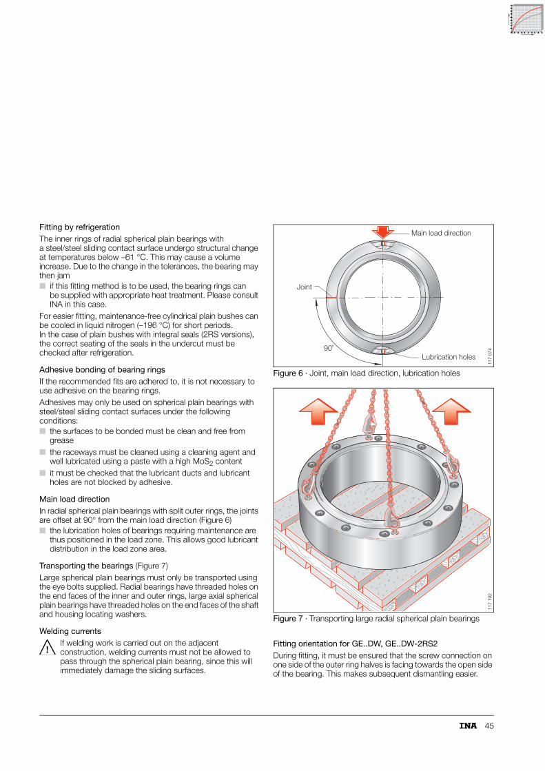
45
Fitting by refrigerationThe inner rings of radial spherical plain bearings with a steel/steel sliding contact surface undergo structural change at temperatures below –61 °C. This may cause a volume increase. Due to the change in the tolerances, the bearing may then jam■ if this fitting method is to be used, the bearing rings can
be supplied with appropriate heat treatment. Please consult INA in this case.
For easier fitting, maintenance-free cylindrical plain bushes can be cooled in liquid nitrogen (–196 °C) for short periods. In the case of plain bushes with integral seals (2RS versions), the correct seating of the seals in the undercut must be checked after refrigeration.
Adhesive bonding of bearing ringsIf the recommended fits are adhered to, it is not necessary to use adhesive on the bearing rings.Adhesives may only be used on spherical plain bearings with steel/steel sliding contact surfaces under the following conditions:■ the surfaces to be bonded must be clean and free from
grease■ the raceways must be cleaned using a cleaning agent and
well lubricated using a paste with a high MoS2 content■ it must be checked that the lubricant ducts and lubricant
holes are not blocked by adhesive.
Main load directionIn radial spherical plain bearings with split outer rings, the joints are offset at 90° from the main load direction (Figure 6)■ the lubrication holes of bearings requiring maintenance are
thus positioned in the load zone. This allows good lubricant distribution in the load zone area.
Transporting the bearings (Figure 7)Large spherical plain bearings must only be transported using the eye bolts supplied. Radial bearings have threaded holes on the end faces of the inner and outer rings, large axial spherical plain bearings have threaded holes on the end faces of the shaft and housing locating washers.
Welding currentsIf welding work is carried out on the adjacent construction, welding currents must not be allowed to pass through the spherical plain bearing, since this will immediately damage the sliding surfaces.
Figure 6 · Joint, main load direction, lubrication holes
Figure 7 · Transporting large radial spherical plain bearings
Fitting orientation for GE..DW, GE..DW-2RS2During fitting, it must be ensured that the screw connection on one side of the outer ring halves is facing towards the open side of the bearing. This makes subsequent dismantling easier.
90˚
Main load direction
Joint
Lubrication holes
117
074
117
192

46
Fitting and dismantling
Dismantling
Even if the load is applied to the ring to be dismantled in accordance with the specification, the frictional contact of the other ring due to the fit presents difficulties in dismantling (Figure 8).Depending on the level of interference, the inner ring will contract and the outer ring will expand. The extraction forces also increase with increasing interference.If the following precautions are taken during design, this will make dismantling of the bearings easier:■ a threaded hole for an extraction screw in the shaft
(Figure 9)■ threaded holes for extraction screws in the housing
(Figure 10)■ milled areas on the stud for the jaws of the extraction device
(Figure 10).Figure 8 · Contraction of the inner ring and expansion of
the outer ring
Figure 9 · Threaded holes in the shaft
Figure 10 · Threaded holes in the housing and milled areas for extraction device
Motion
117
071
117
072
117 073

47
Operating temperatures
The permissible operating temperature is dependent on:■ the sliding contact surface■ the sealing arrangement.
If the operating temperature exceeds the values in Table 1, this will reduce:– the life of the bearing– the efficacy of the sealing arrangement.
If sealed bearings must be used at high temperatures, an unsealed bearing with external heat-resistant seals can be used (Figure 1).The influence of temperature on life is taken into consideration by means of temperature factors.Life calculation:■ Maintenance-free spherical plain bearings
(page 63 to 71)■ Maintenance-free cylindrical plain bushes
(page 72, 73)■ Maintenance-free rod ends
(page 63 to 71 and 128, 129)■ Spherical plain bearings requiring maintenance
(page 97 to 99)■ Rod ends requiring maintenance
(page 97 to 99 and 146 to 148).
Figure 1 · Unsealed spherical plain bearing with external seals
1) Without seals: for temperatures from –60 °C to +200 °C.2) Without seals: for temperatures from –50 °C to +150 °C.
˚C
117
130
Table 1 · Operating temperatures for spherical plain bearings and maintenance-free cylindrical plain bushes
Spherical plain bearings/plain bushes
Series Temperature°C
Reduced life°C
from to from
requiring maintenance
GE..DO –60 +200 +150
GE..DO-2RS1) –30 +130 –
GE..FO –60 +200 +150
GE..FO-2RS1) –30 +130 –
GE..PB –60 +250 +150
GE..LO –60 +200 +150
GE..HO-2RS1) –30 +130 –
GE..ZO –60 +200 +150
GE..SX –60 +200 +150
GE..AX –60 +200 +150
maintenance-free
GE..UK –50 +200 + 95
GE..UK-2RS2) –30 +130 –20
GE..DW –50 +150 –20
GE..DW-2RS22) –40 +120 –20
GE..FW –50 +200 + 95
GE..FW-2RS2) –30 +130 –20
GE..PW –50 +200 +100
GE..SW –50 +150 –20
GE..AW –50 +150 –20
ZGB –50 +150 –20

48
Materials
Maintenance-free spherical plain bearingsMaintenance-free spherical plain bearings have special sliding layers based on PTFE (polytetrafluoroethylene).In descending order of performance, these are:■ ELGOGLIDE® –
the highest performance sliding layer (Figure 1)■ PTFE-bronze film (Figure 2)■ PTFE composite (Figure 3)These materials form the slideway of the outer ring. They transmit loads and provide lubrication – the bearings must not be lubricated by any other means.
Features of ELGOGLIDE®
The sliding layer comprises a 0,5 mm thick layer of ELGOGLIDE®, is embedded in resin and fixed to the bush by a high strength bond. The flow behaviour of the sliding layer is, in combination with the bush, almost negligible even under very high load. The bond is resistant to moisture and swelling.
Series GE..UK-2RS, GE..FW-2RSInner ring:■ Hardened and ground rolling bearing chromium steel■ Spherical surface finished or polished (from �240 mm)
and hard chromium plated.Outer ring:■ Split at one point in
– GE..UK-2RS up to shaft diameter d = 140 mm– GE..FW-2RS up to shaft diameter d = 120 mm
■ In larger bearings, the outer ring is split at two points and held together using heavy-section retaining rings.
Sliding layer (Figure 1):■ ELGOGLIDE® fixed by adhesive in the outer ring spherical
surface.
Large radial spherical plain bearings, series GE..DW/GE..DW-2RS2Inner ring:■ Hardened rolling bearing steel, spherical surface ground,
polished and hard chromium plated.Outer ring:■ 42CrMo4-TQ to EN 10 083-1, radially split and held together
by axially arranged screws and dowel pins on one side.Sliding layer (Figure 1):■ ELGOGLIDE® fixed by adhesive in the outer ring spherical
surface.
Figure 1 · ELGOGLIDE® – cross-section
Series GE..SW, GE..AWInner ring/shaft locating washer:■ Hardened rolling bearing steel, spherical surface ground,
polished and hard chromium plated.Outer ring (in GE..SW)/housing locating washer (in GE..AW):■ Hardened rolling bearing steel, spherical surface ground
– in �GE 160 AW, housing locating washer made from unhardened steel.
Sliding layer (Figure 1):■ ELGOGLIDE® fixed by adhesive in the outer ring spherical
surface.
ResinPTFE fabric composedof Teflon and supporting fibres
Supporting fibres
Adhesiveon steel substrate
®117
132
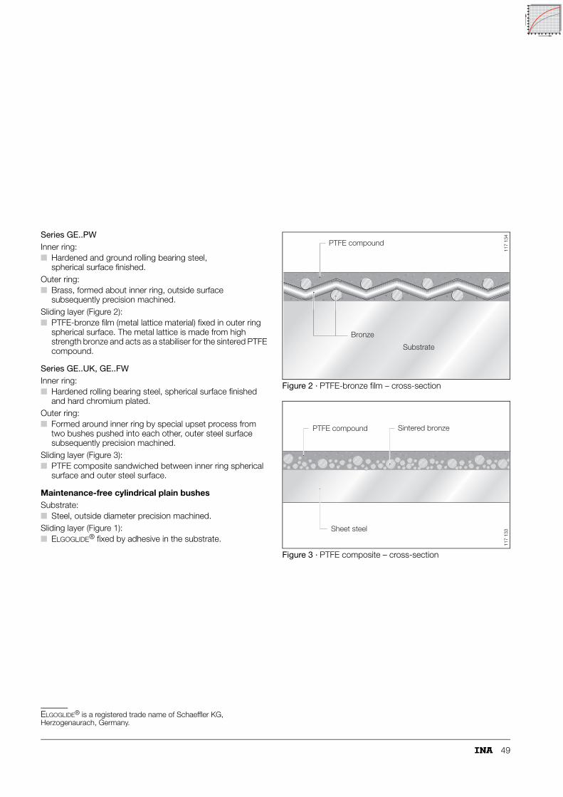
49
Series GE..PWInner ring:■ Hardened and ground rolling bearing steel,
spherical surface finished.Outer ring:■ Brass, formed about inner ring, outside surface
subsequently precision machined.Sliding layer (Figure 2):■ PTFE-bronze film (metal lattice material) fixed in outer ring
spherical surface. The metal lattice is made from high strength bronze and acts as a stabiliser for the sintered PTFE compound.
Series GE..UK, GE..FWInner ring:■ Hardened rolling bearing steel, spherical surface finished
and hard chromium plated.Outer ring:■ Formed around inner ring by special upset process from
two bushes pushed into each other, outer steel surface subsequently precision machined.
Sliding layer (Figure 3):■ PTFE composite sandwiched between inner ring spherical
surface and outer steel surface.
Maintenance-free cylindrical plain bushesSubstrate:■ Steel, outside diameter precision machined.Sliding layer (Figure 1):■ ELGOGLIDE® fixed by adhesive in the substrate.
ELGOGLIDE® is a registered trade name of Schaeffler KG, Herzogenaurach, Germany.
Figure 2 · PTFE-bronze film – cross-section
Figure 3 · PTFE composite – cross-section
PTFE compound
Bronze
Substrate
117
134
PTFE compound Sintered bronze
Sheet steel
117
133

50
Materials
Spherical plain bearings requiring maintenanceThese spherical plain bearings are made from high quality rolling bearing steel. Depending on the bearing size, the raw materials are in the form of tubes, forgings or rolled parts.The sliding contact surface is:■ steel/steel or steel/bronze.The steel bearing rings are turned, hardened, ground on all sides and surface treated.The surface treatment – manganese phosphating with subsequent molybdenum disulphide coating of the sliding surfaces – gives excellent wear resistance. The effective separation of the metallic surfaces gives optimum running-in characteristics.
Series GE..DO, GE..DO-2RS, GE..FO, GE..FO-2RS, GE..LO, GE..HO-2RS, GE..ZO, GE..SX and GE..AXInner ring and outer ring, shaft and housing locating washers:■ Martensitic or bainitic hardened structure with low residual
austenite content.
Series GE..PBInner ring:■ Hardened and ground rolling bearing steel,
spherical surface finished.Outer ring:■ Bronze, formed about inner ring,
outside surface subsequently precision machined.
Rod endsRod ends of dimension series E and K to ISO 12 240-4■ Drop forged quenched and tempered steel C45-TQ to
EN 10 083-2■ Surface zinc plated.
Hydraulic rod ends with internal thread■ � d = 50 mm, drop forged quenched and
tempered steel C45-TN to EN 10 083-2■ � d = 50 mm, spheroidal graphite cast iron GJS 400-15 to
EN 1563■ Surfaces preserved.
Hydraulic rod ends with welding facesSeries GK..DO, dimension series E to ISO 12 240-4■ Drop forged construction steel E355J2G3 to EN 10 025■ Surfaces preserved.
Series GF..DO■ Forged or rolled construction steel E355J2G3 to EN 10 025■ Surfaces preserved.

51
ISO tolerances
Table 1 · ISO tolerances for bores (to ISO 286-2)
Nominal bore diameter in mm
overincl.
610
1018
1830
3050
5080
80120
120180
180250
250315
315400
400500
500630
630800
8001000
10001250
12501600
Bore deviation in �m
G 7 upp.low.
+20+5
+24+ 6
+28+7
+34+9
+40+10
+47+12
+54+14
+61+15
+69+17
+75+18
+83+20
+92+22
+104+24
+116+26
+133+28
+155+30
H 7 upp.low.
+150
+180
+210
+250
+300
+350
+400
+460
+520
+570
+630
+700
+800
+900
+1050
+1250
H 8 upp.low.
+220
+270
+330
+390
+460
+540
+630
+720
+810
+890
+970
+1100
+1250
+1400
+1650
+1950
H 9 upp.low.
+360
+430
+520
+620
+740
+870
+1000
+1150
+1300
+1400
+1550
+1750
+2000
+2300
+2600
+3100
J 6 upp.low.
+5–4
+6–5
+8–5
+10–6
+13–6
+16–6
+18–7
+22–7
+25–7
+29–7
+33–7
+35–8
+38–9
+42–10
+48–10
+54–11
J 7 upp.low.
+8–7
+10–8
+12–9
+14–11
+18–12
+22–13
+26–14
+30–16
+36–16
+39–18
+43–20
+46–22
+52–24
+58–26
+64–29
+72–33
K 7 upp.low.
+5–10
+6–12
+6–15
+7–18
+9–21
+10–25
+12–28
+13–33
+16–36
+17–40
+18–45
0–70
0–80
0–90
0–105
0–125
K 8 upp.low.
+6–16
+8–19
+10–23
+12–27
+14–32
+16–38
+20–43
+22–50
+25–56
+28–61
+29–68
0–110
0–125
0–140
0–165
0–195
M 7 upp.low.
0–15
0–18
0–21
0–25
0–30
0–35
0–40
0–46
0–52
0–57
0–63
–26–96
–30–110
–34–124
–40–145
–48–173
N 7 upp.low.
–4–19
–5–23
–7–28
–8–33
–9–39
–10–45
–12–52
–14–60
–14–66
–16–73
–17–80
–44–114
–50–130
–56–146
–66–171
–78–203
Des
igna
tion
Nom
inal
devi
tatio
n
00
A
E
H J JS
ZC
T
u
A
Au
T
Ao
Ao
A
T o
o
u
Au
E
H J JS
Ag
g
Ag = Ao
Ag = Au
A
g
g
g
ZC
RR
= Upper deviation
= Lower deviation
= Standard tolerance; T = A – A
= Fundamental tolerance(minimum distance from zero line)
Housing
152
118

52
ISO tolerances
Table 2 · ISO tolerances for shafts (to ISO 286-2)
Nominal shaft diameter in mm
overincl.
36
610
1018
1830
3040
4050
5065
6580
80100
100120
120140
140160
160180
180200
200225
225250
Shaft deviations in �m
e 7 upp.low.
–20–32
–25–40
–32–50
–40–61
–50–75
–60–90
–72–107
–85–125
–100–146
f 7 upp.low.
–10–22
–13–28
–16–34
–20–41
–25–50
–30–60
–36–71
–43–83
–50–96
g 6 upp.low.
–4–12
–5–14
–6–17
–7–20
–9–25
–10–29
–12–34
–14–39
–15–44
h 6 upp.low.
0–8
0–9
0–11
0–13
0–16
0–19
0–22
0–25
0–29
h 7 upp.low.
0–12
0–15
0–18
0–21
0–25
0–30
0–35
0–40
0–46
h 8 upp.low.
0–18
0–22
0–27
0–33
0–39
0–46
0–54
0–63
0–72
j 6 upp.low.
+6–2
+7–2
+8–3
+9–4
+11–5
+12–7
+13–9
+14–11
+16–13
j 7 upp.low.
+8–4
+10–5
+12–6
+13–8
+15–10
+18–12
+20–15
+22–18
+25–21
k 6 upp.low.
+9+1
+10+1
+12+1
+15+2
+18+2
+21+2
+25+3
+28+3
+33+4
m 6 upp.low.
+12+4
+15+6
+18+7
+21+8
+25+9
+30+11
+35+13
+40+15
+46+17
n 6 upp.low.
+16+8
+19+10
+23+12
+28+15
+33+17
+39+20
+45+23
+52+27
+60+31
p 6 upp.low.
+20+12
+24+15
+29+18
+35+22
+42+26
+51+32
+59+37
+68+43
+79+50
r 6 upp.low.
+23+15
+28+19
+34+23
+41+28
+50+34
+60+41
+62+43
+73+51
+76+54
+88+63
+90+65
+93+68
+106+77
+109+80
+113+84
Des
igna
tion
Nom
inal
devi
tatio
n

53
250280
280315
315355
355400
400450
450500
500560
560630
630710
710800
800900
9001000
–110–162
–125–182
–135–198
––
––
––
upp.low. e 7
–56–108
–62–119
–68–131
––
––
––
upp.low. f 7
–17–49
–18–54
–20–60
–22–66
–24–74
–26–82
upp.low. g 6
0–32
0–36
0–40
0–44
0–50
0–56
upp.low. h 6
0–52
0–57
0–63
0–70
0–80
0–90
upp.low. h 7
0–81
0–89
0–97
0–110
0–125
0–140
upp.low. h 8
+16–16
+18–18
+20–20
+22–21
+24–23
––
upp.low. j 6
+26–26
+29–28
+31–32
––
––
––
upp.low. j 7
+36+4
+40+4
+45+5
+440
+500
+560
upp.low. k 6
+52+20
+57+21
+63+23
+70+26
+80+30
+90+34
upp.low. m 6
+66+34
+73+37
+80+40
+88+44
+100+50
+112+56
upp.low. n 6
+88+56
+98+62
+108+68
+122+78
+138+88
+156+100
upp.low. p 6
+126+94
+130+98
+144+108
+150+114
+166+126
+172+132
+194+150
+199+155
+225+175
+235+185
+266+210
+276+220
upp.low. r 6
Nom
inal
devi
tatio
n
Des
igna
tion
Ao
T a
e
hj js
zc
0 0
Ao
T
Au
g
g
Ag = Ao
Ag = Au
A
T o
o
u
A u
Ag
g
g
Au
a
e
hj js
a
e
hj js
rrrr
zczc
Shaft
= Upper deviation = Lower deviation
= Standard tolerance; T = A – A
= Fundamental tolerance (minimum distance from zero line)
152
119
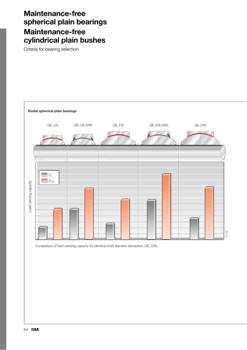
54
Maintenance-free spherical plain bearingsMaintenance-free cylindrical plain bushesCriteria for bearing selection
GE..UK GE..FW GE..PWGE..UK-2RS GE..FW-2RS
C
C0r
r
Radial spherical plain bearings
Load
car
ryin
g ca
paci
ty
Comparison of load carrying capacity for identical shaft diameter (exception: GE..DW).
117
135

55
GE..SWGE..AW ZGB
Ca
C0a
C
C0
r
r
C
C0
r
r
Axial spherical plain bearings
Angular contactspherical plainbearings
Maintenance-freecylindrical plainbushes
Large radial spherical plain bearings
Load
car
ryin
g ca
paci
ty
GE..DW-2RS2GE..DW
117
136

56
Maintenance-free spherical plain bearingsRadial spherical plain bearingsAngular contact spherical plain bearingsAxial spherical plain bearings
Maintenance-free cylindrical plain bushes
Page
Design and safety guidelines ............................. 60
Accuracy ............................................................ 74
Special designs.................................................. 75
Ordering example and ordering designation ..... 75
p.p.SS
Features
Radial spherical plain bearings■ are complete units comprising inner rings and outer rings
with maintenance-free sliding layers– the inner ring has a cylindrical bore and a convex
outer slideway– the outer ring has a cylindrical outside surface and
a concave inner slideway.In series GE..UK-2RS with a bore diameter up to 140 mm, the outer ring is split at one point; for a bore diameter �160 mm, the outer ring is split at two points and held together by heavy-section retaining washers.In series GE..FW-2RS with a bore diameter up to 120 mm, the outer ring is split at one point; for a bore diameter �140 mm, the outer ring is splitat two points and held together by heavy-section retaining washers. In series GE..DW and GE..DW-2RS2, the outer ring is radially split and held together axially by screws and dowel pins
– sliding layers comprising PTFE composite, PTFE-bronze film or ELGOGLIDE®
■ are preferably used to support radial loads■ are completely maintenance-free
– in bearings with ELGOGLIDE®, lubricant leads to a considerable reduction in bearing life
■ are used where:– there are particular requirements on bearing life
under maintenance-free operation– bearings with a metallic sliding contact surface are
not suitable for lubrication reasons, e.g. under unilateral load.
Sealed maintenance-free radial spherical plain bearings■ are protected against contaminants and water spray by
– lip seals.
Radial spherical plain bearings
■ to ISO 12 240-1, dimension series E■ hard chromium/PTFE composite sliding contact surface■ for shaft diameters from 6 mm to 30 mm
■ to ISO 12 240-1, dimension series G■ hard chromium/PTFE composite sliding contact surface■ larger tilt angle � due to wider inner ring■ for shaft diameters from 6 mm to 25 mm
GE..UK
117
076
GE..FW11
7 09
7
76
80
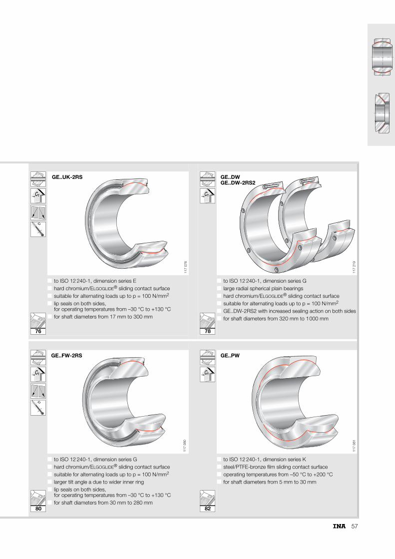
57
˚C
■ to ISO 12 240-1, dimension series E■ hard chromium/ELGOGLIDE® sliding contact surface■ suitable for alternating loads up to p = 100 N/mm2
■ lip seals on both sides, for operating temperatures from –30 °C to +130 °C
■ for shaft diameters from 17 mm to 300 mm
■ to ISO 12 240-1, dimension series G■ large radial spherical plain bearings■ hard chromium/ELGOGLIDE® sliding contact surface■ suitable for alternating loads up to p = 100 N/mm2
■ GE..DW-2RS2 with increased sealing action on both sides■ for shaft diameters from 320 mm to 1000 mm
■ ■
˚C
■ to ISO 12 240-1, dimension series G■ hard chromium/ELGOGLIDE® sliding contact surface■ suitable for alternating loads up to p = 100 N/mm2
■ larger tilt angle a due to wider inner ring■ lip seals on both sides,
for operating temperatures from –30 °C to +130 °C■ for shaft diameters from 30 mm to 280 mm
■ to ISO 12 240-1, dimension series K■ steel/PTFE-bronze film sliding contact surface■ operating temperatures from –50 °C to +200 °C■ for shaft diameters from 5 mm to 30 mm
GE..UK-2RS11
7 07
8
GE..DWGE..DW-2RS2
117
219
GE..FW-2RS
117
080
GE..PW11
7 08
1
78
82
76
80

58
Maintenance-free spherical plain bearings
Angular contact spherical plain bearingsAxial spherical plain bearings
Page
Design and safety guidelines ............................. 60
Accuracy ............................................................ 74
Special designs.................................................. 75
Ordering example and ordering designation ..... 75
p.p.SS
Features
Angular contact spherical plain bearings■ are complete units comprising an inner ring and outer ring
with ELGOGLIDE®
– the inner ring has a convex outer slideway– the outer ring has a concave inner slideway and
ELGOGLIDE® secured by adhesive■ can support axial loads as well as radial loads
– they are thus suitable for alternating dynamic loads■ can be used in paired arrangements as preloaded units■ are used, for example, to support high loads in
conjunction with small motions– they are a plain bearing alternative to tapered roller
bearings■ are maintenance-free throughout their operating life
– the use of lubricant leads to a considerable reduction in bearing life.
Axial spherical plain bearings■ are complete units comprising shaft and housing locating
washers with ELGOGLIDE®
– the shaft locating washer is supported in the ball socket-shaped sliding zone of the housing locating washer
– the housing locating washer has ELGOGLIDE® secured by adhesive
■ are preferably used to support axial loads■ are suitable for use as support or base bearings■ can be combined with radial spherical plain bearings
of dimension series E to ISO 12 240-1■ are maintenance-free throughout their operating life
– the use of lubricant leads to a considerable reduction in bearing life.
Angular contact spherical plain bearings
■ to ISO 12 240-2■ mounting dimensions as for
tapered roller bearings to DIN 720, 320X■ hard chromium/ELGOGLIDE® sliding contact surface■ for shaft diameters from 25 mm to 200 mm
Axial spherical plain bearings
■ to ISO 12 240-3■ hard chromium/ELGOGLIDE® sliding contact surface■ for shaft diameters from 10 mm to 360 mm■ from d � 220 mm,
classified as large axial spherical plain bearings
GE..SW
117
091
GE..AW11
7 09
2
84
86

59
Maintenance-free cylindrical plain bushes Page
Design and safety guidelines............................. 60
Accuracy............................................................ 74
Special designs ................................................. 75
Ordering example and ordering designation ..... 75
p.p.SS
Features
Maintenance-free cylindrical plain bushes■ are radial dry plain bearings comprising a cylindrical steel
bush and ELGOGLIDE®
– the steel bush gives protection during handling and fitting
■ are maintenance-free throughout their operating life– the use of lubricant leads to a considerable reduction
in bearing life■ can be used to replace steel, bronze and plastic
plain bearings– the plain bushes can support higher loads than
conventional plain bearings■ can support very high radial loads with unilateral load
direction and high static loads■ are used with high alternating loads and swivel motion■ have low friction■ have good damping characteristics■ allow some axial motion■ are easy to fit
– they are simply pressed into the housing bore– no further axial location is required
■ can also be combined with separate, additional seals.
Maintenance-free cylindrical plain bush
■ dimensions to ISO 4 379, diameter series 2 and 3■ operating temperatures from –50 °C to +150 °C■ for shaft diameters from 30 mm to 200 mm
■
ZGB
117
098
88
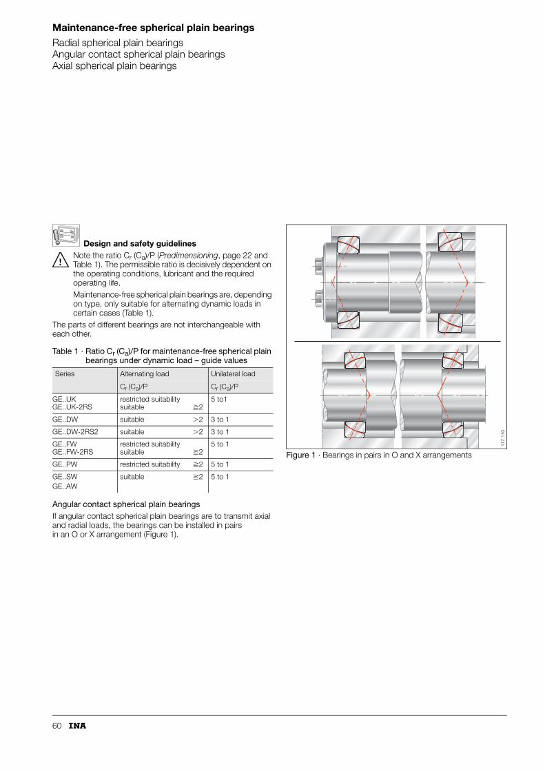
60
Maintenance-free spherical plain bearings
Radial spherical plain bearingsAngular contact spherical plain bearingsAxial spherical plain bearings
Design and safety guidelinesNote the ratio Cr (Ca)/P (Predimensioning, page 22 and Table 1). The permissible ratio is decisively dependent on the operating conditions, lubricant and the required operating life.Maintenance-free spherical plain bearings are, depending on type, only suitable for alternating dynamic loads in certain cases (Table 1).
The parts of different bearings are not interchangeable with each other.
Angular contact spherical plain bearingsIf angular contact spherical plain bearings are to transmit axial and radial loads, the bearings can be installed in pairs in an O or X arrangement (Figure 1).
Figure 1 · Bearings in pairs in O and X arrangements
Table 1 · Ratio Cr (Ca)/P for maintenance-free spherical plain bearings under dynamic load – guide values
Series Alternating load Unilateral load
Cr (Ca)/P Cr (Ca)/P
GE..UKGE..UK-2RS
restricted suitabilitysuitable �2
5 to1
GE..DW suitable �2 3 to 1
GE..DW-2RS2 suitable �2 3 to 1
GE..FWGE..FW-2RS
restricted suitabilitysuitable �2
5 to 1
GE..PW restricted suitability �2 5 to 1
GE..SWGE..AW
suitable �2 5 to 1
117
110
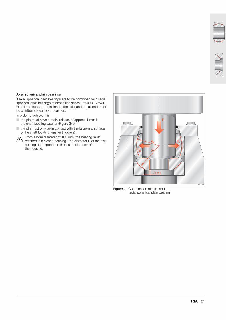
61
Axial spherical plain bearingsIf axial spherical plain bearings are to be combined with radial spherical plain bearings of dimension series E to ISO 12 240-1 in order to support radial loads, the axial and radial load must be distributed over both bearings.In order to achieve this:■ the pin must have a radial release of approx. 1 mm in
the shaft locating washer (Figure 2) or■ the pin must only be in contact with the large end surface
of the shaft locating washer (Figure 2).From a bore diameter of 160 mm, the bearing must be fitted in a closed housing. The diameter D of the axial bearing corresponds to the inside diameter of the housing.
Figure 2 · Combination of axial and radial spherical plain bearing
F
FddK
dd K
1mm
R
FR
117 220

62
Maintenance-free cylindrical plain bushes
Maintenance-free cylindrical plain bushesDo not lubricate the sliding layer. Lubricant increases wear and considerably reduces the operating life of the bearing.Plain bushes should not be used for movement involving spatial alignment. Any skewing of the shaft reduces the bearing life.
For applications involving contact with water, plain bushes with a corrosion-resistant steel bush must be used. The “flushing effect” will considerably increase wear of the sliding layer. If movement is infrequent, however, the operating life may nevertheless be sufficient. The design of the plain bush andits suitability should be agreed with INA first.If plain bushes come into contact with chemical media, special measures will often be required for the bush material or the surface treatment. The design of the plain bush and its suitability should be agreed with INA first.
Design of bearing arrangementsThe shaft and housing bore should conform to Figure 3.■ For optimum conditions, the shaft should be hardened and
hard chromium plated or corrosion-resistant steel should be used.
■ The shaft roughness should not exceed Rz1 if possible. Higher roughness values will reduce the operating life of plain bushes. Roughness values � Rz4 should be avoided.
If plain bushes are combined with outer seals, it must be taken into consideration when designing the sealing arrangement that:■ the internal clearance will increase due to wear of the sliding
layer■ the plain bush cannot be relubricated.
FittingPlain bushes should be pressed in using a fitting arbor (Figure 5).The chamfer of the fitting arbor must have rounded corners or ends:■ dD = d – (0,3 mm to 0,5 mm).
Sharp corners on the entry side of the shaft and arbor will damage the sliding layer and reduce the operating life of the plain bush.
Figure 3 · Design of adjacent components
Figure 4 · Tolerances of plain bushes
Figure 5 · Fitting by means of an arbor
ShaftHousing
15˚
5
Rz1
dwf 7
Rz10
DAH7
15˚
�
Rz10
rounded
rounded
153
062
D dH8
B h12
p7
153
063
dD
Fitting arbor
153
064

63
Maintenance-free spherical plain bearings
Radial spherical plain bearingsAngular contact spherical plain bearingsAxial spherical plain bearings
Calculation of rating lifeIn maintenance-free spherical plain bearings, the sliding surfaces are in direct contact due to the lack of lubricant. This leads to wear. Wear of the sliding surface is therefore the principal failure criterion in life calculation.Due to wear, the friction increases towards the end of the operating life.In some cases, low sliding speeds and low bearing loads can result in very high calculated life values. With very long running times, however, parameters that are not taken into consideration in calculation can have a considerable influence on the life; these include:■ vibration■ contamination■ moisture■ corrosion■ ageing.The actual life may therefore differ considerably from these values.
The operating life of large spherical plain bearings of series GE..DW and GE..DW-2RS2 cannot be determined using the calculation method presented here – particular attention must be paid to the specific environmental conditions in each application. Please consult INA in this case.In the case of axial bearings with d � 220 mm, particular attention must be paid to the surrounding constructions and operating conditions. Please consult INA in this case.
Further information PageLoad carrying capacity and life............................. 17Friction................................................................. 26Lubrication............................................................ 28Internal clearance and operating clearance ........... 30Design of bearing arrangements ........................... 37Sealing ................................................................. 40Fitting and dismantling .......................................... 42Operating temperatures ........................................ 47Materials ............................................................... 48ISO tolerances ...................................................... 51
64
Maintenance-free spherical plain bearings
Radial spherical plain bearingsAngular contact spherical plain bearingsAxial spherical plain bearings
Life calculation for maintenance-free spherical plain bearings – sliding material ELGOGLIDE®
Scope
Failure criteriaIncrease in radial internal clearance with:
■ Radial spherical plain bearings 17 mm � d � 300 mm■ Angular contact
spherical plain bearings 25 mm � d � 200 mm■ Axial spherical plain bearings 10 mm � d � 200 mm■ Temperature range –50 °C � t � +150 °C
(note the restrictions in Table 1, page 47)■ Contact pressure
– constant load 5 N/mm2 � p � 300 N/mm2
– variable load 5 N/mm2 � p � 100 N/mm2
■ Sliding speed 1 mm/s � v � 296 mm/s■ Bearing dry, without lubrication■ Angular contact spherical plain bearing
set axially free from clearance■ Sliding speed factor fv � 0,2;
at fv � 0,8, good heat dissipation required.
■ unilateral load direction by 0,5 mm■ alternating load direction by 1,0 mm
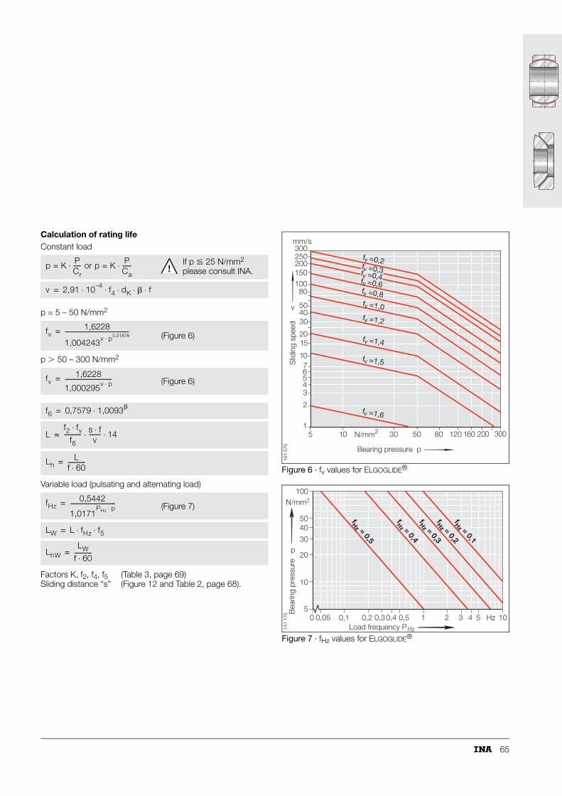
65
Calculation of rating lifeConstant load
p = 5 – 50 N/mm2
p � 50 – 300 N/mm2
Variable load (pulsating and alternating load)
Figure 6 · fv values for ELGOGLIDE®
Figure 7 · fHz values for ELGOGLIDE®
Factors K, f2, f4, f5Sliding distance “s”
(Table 3, page 69)(Figure 12 and Table 2, page 68).
p K PCr-----⋅= or p K P
Ca------⋅= If p � 25 N/mm2
please consult INA.
v 2,91 10–4 f4 dK � f⋅ ⋅ ⋅ ⋅ ⋅=
fv1,6228
1,004243v p0,31876⋅---------------------------------------------= (Figure 6)
fv1,6228
1,000295v p⋅---------------------------------= (Figure 6)
f6 0,7579 1,0093�⋅=
Lf2 fv⋅
f6------------ s f⋅
v-------- 14⋅ ⋅=
LhL
f 60⋅------------=
fHz0,5442
1,0171PHz p⋅
--------------------------------= (Figure 7)
LW L fHz f5⋅ ⋅=
LhWLW
f 60⋅------------=
1
2
34567
10
1520
304050
80100150200250300
5 10 30 50 80 120 160 200 300N/mm2
Bearing pressure p
Slid
ing
spee
d
fv =1,6
fv =1,5
fv =1,4
fv =1,2
fv =1,0
fv =0,6
fv =0,4fv =0,3
fv =0,2
fv =0,8
mm/s
v
151
575
p
100N/mm2
5040
30
20
10
50 0,05 0,1 0,2 0,30,4 0,5 1 2 3 4 5 Hz 10
Load frequency P
Bea
ring
pres
sure
Hz
fHz = 0,4
fHz = 0,2
fHz = 0,1
fHz = 0,3
fHz = 0,5
151
175
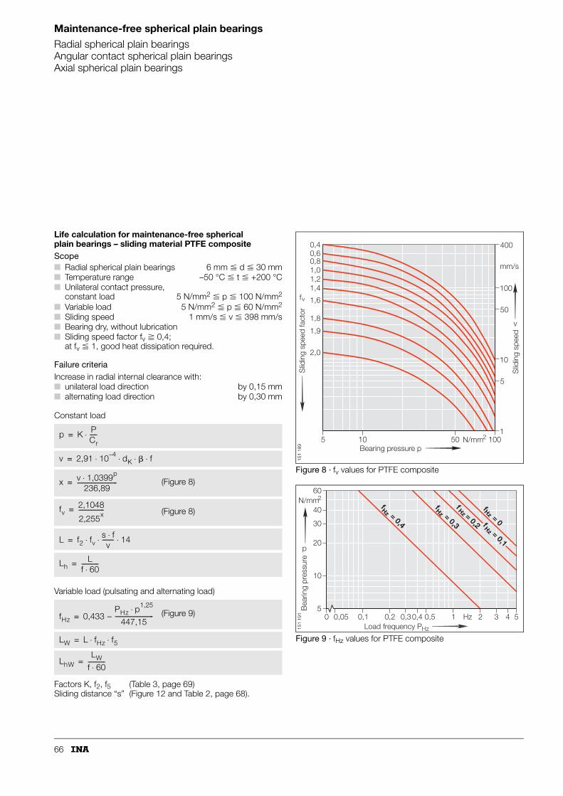
66
Maintenance-free spherical plain bearings
Radial spherical plain bearingsAngular contact spherical plain bearingsAxial spherical plain bearings
Life calculation for maintenance-free spherical plain bearings – sliding material PTFE compositeScope
Failure criteriaIncrease in radial internal clearance with:
Constant load
Variable load (pulsating and alternating load)
Figure 8 · fv values for PTFE composite
Figure 9 · fHz values for PTFE composite
■ Radial spherical plain bearings 6 mm � d � 30 mm■ Temperature range –50 °C � t � +200 °C■ Unilateral contact pressure,
constant load 5 N/mm2 � p � 100 N/mm2
■ Variable load 5 N/mm2 � p � 60 N/mm2
■ Sliding speed 1 mm/s � v � 398 mm/s■ Bearing dry, without lubrication■ Sliding speed factor fv � 0,4;
at fv � 1, good heat dissipation required.
■ unilateral load direction by 0,15 mm■ alternating load direction by 0,30 mm
Factors K, f2, f5Sliding distance “s”
(Table 3, page 69)(Figure 12 and Table 2, page 68).
p K PCr-----⋅=
v 2,91 10–4 dK � f⋅ ⋅ ⋅ ⋅=
x v 1,0399p⋅236,89
----------------------------= (Figure 8)
fv2,1048
2,255x------------------= (Figure 8)
L f2 fvs f⋅v
-------- 14⋅ ⋅ ⋅=
LhL
f 60⋅------------=
fHz 0,433 – PHz p1,25⋅
447,15---------------------------= (Figure 9)
LW L fHz f5⋅ ⋅=
LhWLW
f 60⋅------------=
mm/s
v
fv1,41,21,00,80,60,4
1,6
1,8
1,9
2,0
100
400
N/mm25 10 50 1001
5
10
50S
lidin
g sp
eed
fact
or
Slid
ing
spee
d
Bearing pressure p
151
189
N/mm2
p
Hz
Hz5
10
20
30
40
60
0 0,05 0,1 0,2 0,30,4 0,5 1 2 3 4 5
f = 0,3
f = 0,2
Hz Hz
f = 0
f = 0,4
Hz Hz
f = 0,1
Hz
Load frequency P
Bea
ring
pres
sure
151
191
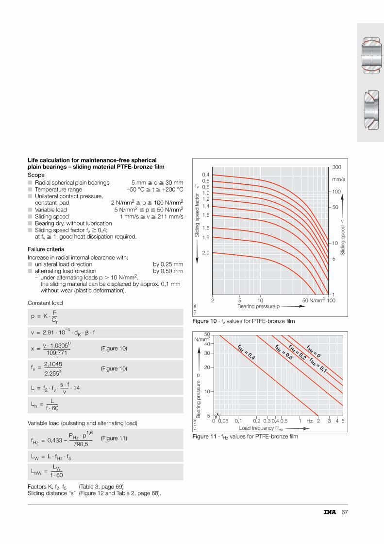
67
Life calculation for maintenance-free spherical plain bearings – sliding material PTFE-bronze filmScope
Failure criteriaIncrease in radial internal clearance with:
Constant load
Variable load (pulsating and alternating load)
Figure 10 · fv values for PTFE-bronze film
Figure 11 · fHz values for PTFE-bronze film
■ Radial spherical plain bearings 5 mm � d � 30 mm■ Temperature range –50 °C � t � +200 °C■ Unilateral contact pressure,
constant load 2 N/mm2 � p � 100 N/mm2
■ Variable load 5 N/mm2 � p � 50 N/mm2
■ Sliding speed 1 mm/s � v � 211 mm/s■ Bearing dry, without lubrication■ Sliding speed factor fv � 0,4;
at fv � 1, good heat dissipation required.
■ unilateral load direction by 0,25 mm■ alternating load direction by 0,50 mm
– under alternating loads p � 10 N/mm2, the sliding material can be displaced by approx. 0,1 mm without wear (plastic deformation).
Factors K, f2, f5Sliding distance “s”
(Table 3, page 69)(Figure 12 and Table 2, page 68).
p K PCr-----⋅=
v 2,91 10–4 dK � f⋅ ⋅ ⋅ ⋅=
x v 1,0305p⋅109,771
----------------------------= (Figure 10)
fv2,1048
2,255x------------------= (Figure 10)
L f2 fvs f⋅v
-------- 14⋅ ⋅ ⋅=
LhL
f 60⋅------------=
fHz 0,433 – PHz p1,6⋅
790,5------------------------= (Figure 11)
LW L fHz f5⋅ ⋅=
LhWLW
f 60⋅------------=
1,41,21,00,80,60,4
v
fv
10
50
100
300
mm/s
1,6
1,8
1,9
2,0
N/mm22 5 10 50 1001
5
Slid
ing
spee
d fa
ctor
Slid
ing
spee
d
Bearing pressure p
151
187
N/mm2
p
Hz
5
10
20
40
30
50
0 0,05 0,1 0,2 0,3 0,4 0,5 1 2 3 4 5Hz
f = 0,3
f = 0,2
Hz Hzf = 0
f = 0,4
Hz Hz
f = 0,1
Hz
Load frequency P
Bea
ring
pres
sure
151
188
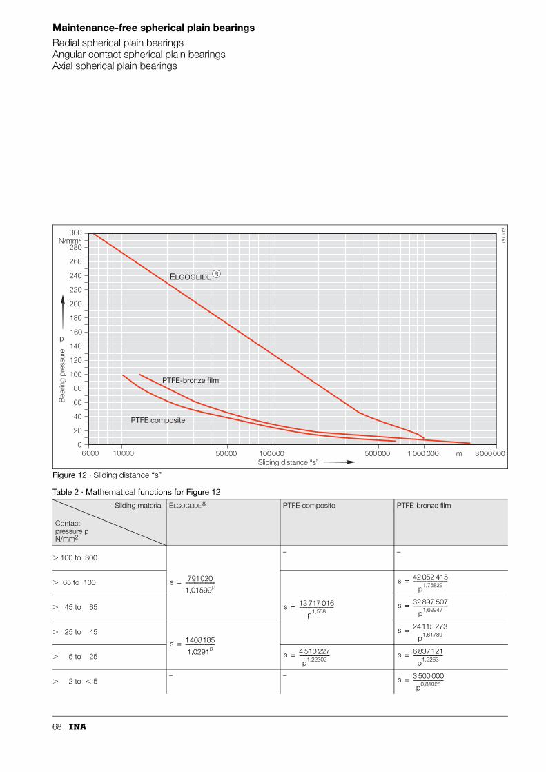
68
Maintenance-free spherical plain bearings
Radial spherical plain bearingsAngular contact spherical plain bearingsAxial spherical plain bearings
Figure 12 · Sliding distance “s”
Table 2 · Mathematical functions for Figure 12
Sliding material
Contact pressure pN/mm2
ELGOGLIDE® PTFE composite PTFE-bronze film
� 100 to 300– –
� 65 to 100
� 45 to 65
� 25 to 45
� 5 to 25
� 2 to 5– –
100006000 50000 100000 500000 1 000 000 3000000m0
20
40
60
80
100
120
140
160
180
200
220
240
260
280
300N/mm2
p
ELGOGLIDE R
Sliding distance “s”
Bea
ring
pres
sure
PTFE-bronze film
PTFE composite
151
173
s 791020
1,01599p------------------------=
s 13 717 016
p1,568----------------------------=
s 42 052 415
p1,75829----------------------------=
s 32 897 507
p1,69947----------------------------=
s 1408185
1,0291p------------------------=
s 24115 273
p1,61789----------------------------=
s 4 510 227
p1,22302-------------------------= s 6 837121
p1,2263------------------------=
s 3 500 000
p0,81025-------------------------=

69
1) For predominantly swivel motion. For predominantly elliptical tilting motion, use f4 = 1.
Symbols, units and definitionsp N/mm2
Specific bearing load, contact pressure
P NEquivalent dynamic bearing load
Cr (Ca) NBasic dynamic load rating (dimension table, Cr radial, Ca axial)
K N/mm2
Basic load rating factor (Table 3)
v mm/sMean sliding speed
dK mmSphere diameter (dimension table)
� °Swivel or oscillation angle(from end position to end position, for rotary motion � = 180°, see page 24 and 25; use � = �1)
f min–1
Oscillation frequency or speed
PHz HzLoad frequency
fHz –
f2 –Temperature factor (Table 3)
f4 –Bearing design factor (Table 3)
f5 –Load type factor (Table 3)
f6 –Swivel or oscillation angle factor (formula) (page 65)
fv –
s mSliding distance (Figure 12 and Table 2, page 68)
L oscillationsTheoretical life under constant load
Lh hTheoretical life under constant load
LW oscillationsTheoretical life under variable load
LhW hTheoretical life under variable load
t °COperating temperature
�1 °Tilt angle from centre to left
�2 °Tilt angle from centre to right.
Table 3 · Factors for life calculation
Sliding materialFactor
ELGOGLIDE® PTFE composite PTFE-bronze film
Basic load rating factorK
N/mm2 300 100 100
Temperature factorf2
Temperature range °C –20 to +150 –20 to –50 –50 to +95 �+95 to +200 –50 to +100 �+100 to +200
f2 1 0,7 1 163 341 · t–2,64 1 1,5 – 0,005 · t
Bearing design factorf4
Radial spherical plain bearings
1 – –
Angular contact spherical plain bearings1)
0,9 – –
Axial spherical plain bearings1)
0,7 – –
Load type factorf5
Alternating load 1 1 1
pulsating load 1,4 1,4 1,4
Factor for variable load (ELGOGLIDE®, Figure 7, page 65, PTFE composite, Figure 9, page 66, PTFE-bronze film, Figure 11, page 67)
Sliding speed factor (ELGOGLIDE®, Figure 6, page 65, PTFE composite, Figure 8, page 66, PTFE-bronze film, Figure 10, page 67)
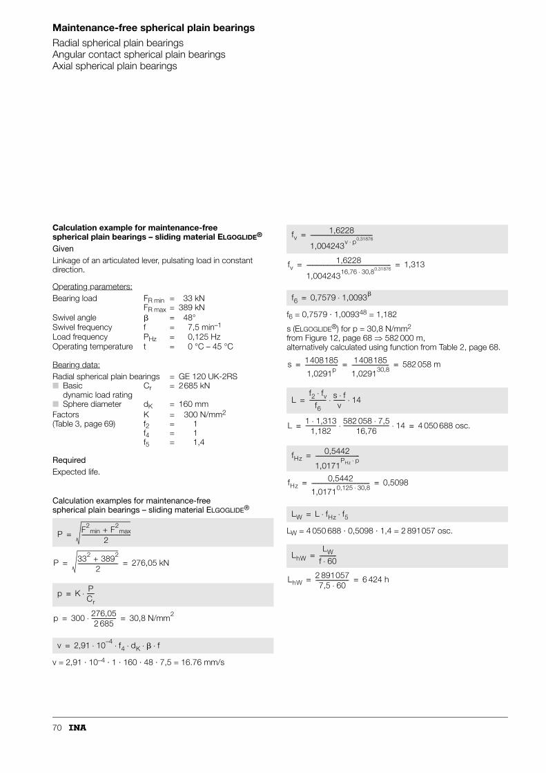
70
Maintenance-free spherical plain bearings
Radial spherical plain bearingsAngular contact spherical plain bearingsAxial spherical plain bearings
Calculation example for maintenance-free spherical plain bearings – sliding material ELGOGLIDE®
GivenLinkage of an articulated lever, pulsating load in constant direction.
Operating parameters:
Bearing data:
RequiredExpected life.
Calculation examples for maintenance-free spherical plain bearings – sliding material ELGOGLIDE®
v = 2,91 · 10–4 · 1 · 160 · 48 · 7,5 = 16.76 mm/s
f6 = 0,7579 · 1,009348 = 1,182
s (ELGOGLIDE®) for p = 30,8 N/mm2
from Figure 12, page 68 ⇒ 582 000 m, alternatively calculated using function from Table 2, page 68.
LW = 4 050 688 · 0,5098 · 1,4 = 2 891057 osc.
Bearing load FR minFR max
==
33 kN389 kN
Swivel angle � = 48°Swivel frequency f = 7,5 min–1
Load frequency PHz = 0,125 HzOperating temperature t = 0 °C – 45 °C
Radial spherical plain bearings = GE 120 UK-2RS■ Basic
dynamic load rating■ Sphere diameter
Cr
dK
=
=
2685 kN
160 mmFactors(Table 3, page 69)
Kf2f4f5
====
300 N/mm2
111,4
P F2min + F2
max
2------------------------------------=
P 332 + 3892
2----------------------------- 276,05 kN= =
p K PCr-----⋅=
p 300 276,052 685
------------------⋅ 30,8 N/mm2= =
v 2,91 10–4 f4 dK � f⋅ ⋅ ⋅ ⋅ ⋅=
fv1,6228
1,004243v p0,31876⋅---------------------------------------------=
fv1,6228
1,00424316,76 30,8⋅ 0,31876------------------------------------------------------------- 1,313= =
f6 0,7579 1,0093�⋅=
s 1408185
1,0291p------------------------ 1408185
1,029130,8--------------------------- 582 058 m= = =
Lf2 fv⋅
f6------------ s f⋅
v-------- 14⋅ ⋅=
L 1 1,313⋅1,182
---------------------- 582 058 7,5⋅16,76
--------------------------------- 14⋅ ⋅ 4 050 688 osc.= =
fHz0,5442
1,0171PHz p⋅
--------------------------------=
fHz0,5442
1,01710,125 30,8⋅------------------------------------------ 0,5098= =
LW L fHz f5⋅ ⋅=
LhWLW
f 60⋅------------=
LhW2 8910577,5 60⋅
------------------------ 6 424 h= =

71
Calculation example for maintenance-free spherical plain bearings – PTFE composite sliding contact surfaceGivenLinkage bearing arrangement of a transfer unit, unilateral combined load.
Operating parameters:
Bearing data:
RequiredRequired life approx. 5 000 h.
Calculation
X (Figure 4, page 18 ⇒ = 1,23P = 1,23 · 16 = 19,7 kN
v = 2,91 · 10–4 · 35,5 · 27 · 12 = 3,35 mm/s
s (PTFE composite) for p = 38,63 N/mm2 from Figure 12, page 68 ⇒ 44 000 m, alternatively calculated using function from Table 2, page 68.
L = 3 827 970 oscillations
Lh = 5 316 h – a safety margin of 1,06.
Bearing load FRFA
==
161,2
kNkN
Swivel angle � = 27°Swivel frequency f = 12 min–1
Operating temperature t = +100 °C
Radial spherical plain bearings = GE 25 UK■ Basic
dynamic load rating■ Sphere diameter
Cr
dK
=
=
51kN
35,5 mmFactors(Table 3, page 69)
Kf2
==
100 N/mm2
163 341 · t–2,64
P X FR⋅=
FA
FR------ 1,2
16-------- 0,075= =
p K PCr-----⋅=
p 100 19,751
-----------⋅ 38,63 N/mm2= =
v 2,91 10–4 dK � f⋅ ⋅ ⋅ ⋅=
x v 1,0399p⋅236,89
----------------------------=
x 3,35 1,039938,63⋅236,89
---------------------------------------------- 0,0641= =
fv2,1048
2,255x------------------=
fv2,1048
2,2550,0641----------------------------- 1,998= =
s 13 717 016
p1,568---------------------------- 13 717 016
38,631,568---------------------------- 44 567 m= = =
L f2 fvs f⋅v
-------- 14⋅ ⋅ ⋅=
L 163 341 t–2,64⋅( ) fvs f⋅v
-------- 14⋅ ⋅ ⋅=
L 163 341 100–2,64⋅( ) 1,998 44 567 12⋅3,35
---------------------------- 14⋅ ⋅ ⋅=
LhL
f 60⋅------------=
Lh3 827 970
12 60⋅------------------------- 5 316 h= =
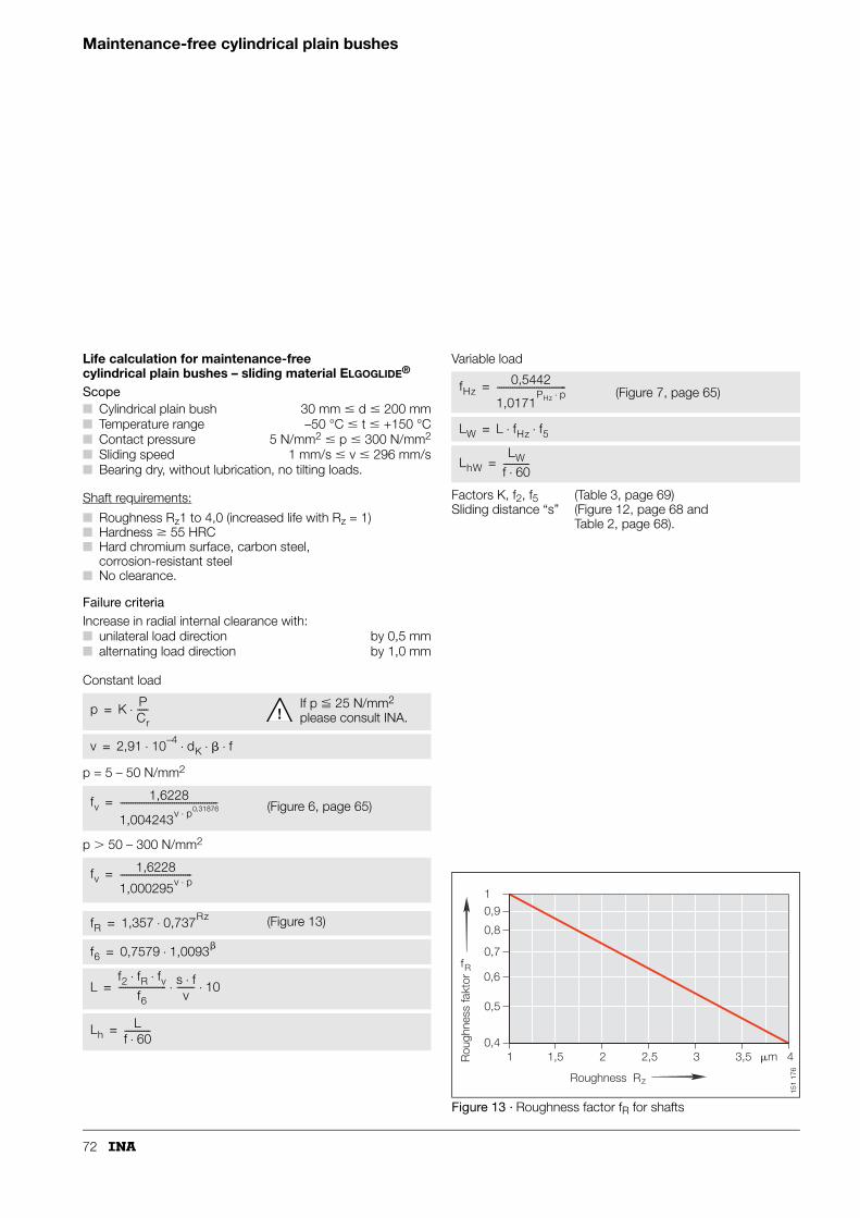
72
Maintenance-free cylindrical plain bushes
Life calculation for maintenance-free cylindrical plain bushes – sliding material ELGOGLIDE®
Scope
Shaft requirements:
■ Roughness Rz1 to 4,0 (increased life with Rz = 1)■ Hardness � 55 HRC■ Hard chromium surface, carbon steel,
corrosion-resistant steel■ No clearance.
Failure criteriaIncrease in radial internal clearance with:
Constant load
p = 5 – 50 N/mm2
p � 50 – 300 N/mm2
Variable load
Figure 13 · Roughness factor fR for shafts
■ Cylindrical plain bush 30 mm � d � 200 mm■ Temperature range –50 °C � t � +150 °C■ Contact pressure 5 N/mm2 � p � 300 N/mm2
■ Sliding speed 1 mm/s � v � 296 mm/s■ Bearing dry, without lubrication, no tilting loads.
■ unilateral load direction by 0,5 mm■ alternating load direction by 1,0 mm
p K PCr-----⋅= If p � 25 N/mm2
please consult INA.
v 2,91 10–4 dK � f⋅ ⋅ ⋅ ⋅=
fv1,6228
1,004243v p0,31876⋅---------------------------------------------= (Figure 6, page 65)
fv1,6228
1,000295v p⋅---------------------------------=
fR 1,357 0,737Rz⋅= (Figure 13)
f6 0,7579 1,0093�⋅=
Lf2 fR fv⋅ ⋅
f6---------------------- s f⋅
v-------- 10⋅ ⋅=
LhL
f 60⋅------------=
Factors K, f2, f5Sliding distance “s”
(Table 3, page 69)(Figure 12, page 68 and Table 2, page 68).
fHz0,5442
1,0171PHz p⋅
--------------------------------= (Figure 7, page 65)
LW L fHz f5⋅ ⋅=
LhWLW
f 60⋅------------=
1 1,5 2 2,5 3 3,5 40,4
0,5
0,6
0,7
0,8
0,91
Roughness R
Rou
ghne
ss fa
ktor
�m
z
fR
151
176
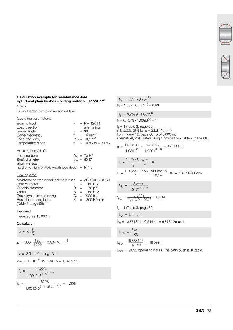
73
Calculation example for maintenance-free cylindrical plain bushes – sliding material ELGOGLIDE®
GivenHighly loaded pivots on an angled lever.
Operating parameters:
Housing bore/shaft:
Bearing data:
RequiredRequired life 10 000 h.
Calculation
v = 2,91 · 10–4 · 60 · 30 · 6 = 3,14 mm/s
fR = 1,357 · 0,7371,6 = 0,83
f6 = 0,7579 · 1,009330 = 1
f2 = 1 (Table 3, page 69)s (ELGOGLIDE®) for p = 33,34 N/mm2 from Figure 12, page 68 ⇒ 540 000 m, alternatively calculated using function from Table 2, page 68.
f5 = 1 (Table 3, page 69)
LW = 13371841 · 0,514 · 1 = 6 873 126 osc.
LhW = 19 092 operating hours. The plain bush is suitable.
Bearing load F = P = 120 kNLoad direction = alternatingSwivel angle � = 30°Swivel frequency f = 6 min–1
Load frequency PHz = 0,1 s–1
Temperature range t = 0 °C to + 30 °C
Locating bore DA = 70 H7Shaft diameter dW = 60 f7Shaft surfacehard chromium plated, roughness depth = Rz1,6
Maintenance-free cylindrical plain bush = ZGB 60�70�60Bore diameter d = 60 H8Outside diameter D = 70 p7Width B = 60 h12Basic dynamic load rating Cr = 1080 kNBasic load rating factor (Table 3, page 69)
K = 300 N/mm2
p K PCr-----⋅=
p 300 1201080-------------⋅ 33,34 N/mm2
= =
v 2,91 10–4 dK � f⋅ ⋅ ⋅ ⋅=
fv1,6228
1,004243v p0,31876⋅---------------------------------------------=
fv1,6228
1,0042433,14 33,340,31876⋅------------------------------------------------------------- 1,558= =
fR 1,357 0,737Rz⋅=
f6 0,7579 1,0093�⋅=
s 1408185
1,0291p------------------------ 1408185
1,029133,34------------------------------ 541158 m= = =
Lf2 fR fv⋅ ⋅
f6---------------------- s f⋅
v-------- 10⋅ ⋅=
L 1 0,83 1,558⋅ ⋅1
--------------------------------------- 541158 6⋅3,14
--------------------------- 10⋅ ⋅ 13 371841 osc.= =
fHz0,5442
1,0171PHz p⋅
--------------------------------=
fHz0,5442
1,01710,1 33,33⋅---------------------------------------- 0,514= =
LW L fHz f5⋅ ⋅=
LhWLW
f 60⋅------------=
LhW6 873126
6 60⋅------------------------ 19 092 h= =
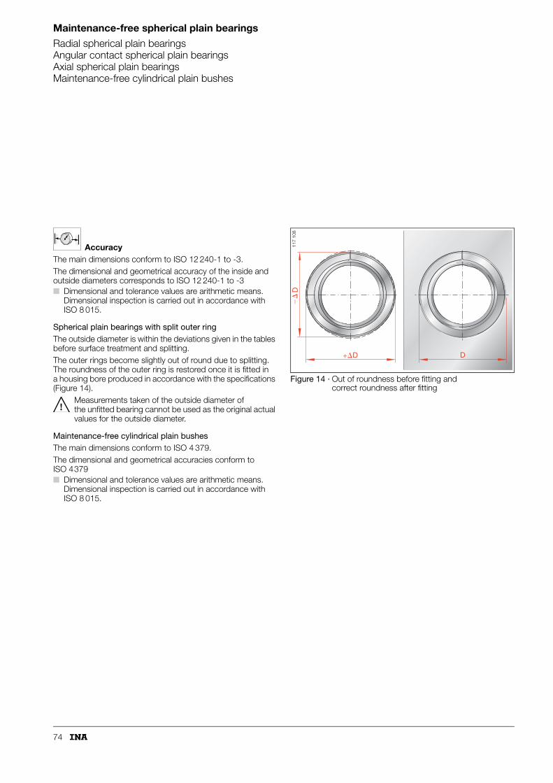
74
Maintenance-free spherical plain bearings
Radial spherical plain bearingsAngular contact spherical plain bearingsAxial spherical plain bearingsMaintenance-free cylindrical plain bushes
AccuracyThe main dimensions conform to ISO 12 240-1 to -3.The dimensional and geometrical accuracy of the inside and outside diameters corresponds to ISO 12 240-1 to -3■ Dimensional and tolerance values are arithmetic means.
Dimensional inspection is carried out in accordance with ISO 8 015.
Spherical plain bearings with split outer ringThe outside diameter is within the deviations given in the tables before surface treatment and splitting.The outer rings become slightly out of round due to splitting. The roundness of the outer ring is restored once it is fitted in a housing bore produced in accordance with the specifications (Figure 14).
Measurements taken of the outside diameter of the unfitted bearing cannot be used as the original actual values for the outside diameter.
Maintenance-free cylindrical plain bushesThe main dimensions conform to ISO 4 379.The dimensional and geometrical accuracies conform to ISO 4379■ Dimensional and tolerance values are arithmetic means.
Dimensional inspection is carried out in accordance with ISO 8 015.
Figure 14 · Out of roundness before fitting and correct roundness after fitting
D
�
+ D
D11
7 10
8

75
Special designsAvailable by agreement (see also page 13):■ maintenance-free radial spherical plain bearings with
inner ring made from corrosion-resistant steel– suffix W3
■ maintenance-free radial spherical plain bearings, inner ring bore with ELGOGLIDE® lining, bore diameter smaller than nominal dimension (dNEW = d – 1,08)– suffix W7
■ maintenance-free radial spherical plain bearing,inner ring bore with ELGOGLIDE® lining (dNEW = d)– suffix W8.
Ordering example and ordering designationMaintenance-free radial spherical plain bearing to ISO 12 240-1-dimension series E, sliding contact surface hard chromium/ELGOGLIDE®, lip seals on both sides, for:
Ordering designation: GE 20 UK-2RS (Figure 15).
Maintenance-free cylindrical plain bush to ISO 4 379, for:
Ordering designation: ZGB 30�36�30 (Figure 16).
Figure 15 · Ordering example, ordering designation
Figure 16 · Ordering example, ordering designation
shaft 20 mm.
shaft 30 mm.
p.p.SS
GE 20 UK-2RS
d
117
109
ZGB 30 36 + +
B
D d
ZGB 30�36� 30
117
138

76
Radial spherical plain bearingsmaintenance-freeISO 12 240-1, dimension series ESliding contact surface: hard chromium/PTFE
Series GE..UKSliding material: PTFE composite
GE..UK-2RSSliding material: ELGOGLIDE®
GE..UK
BC
D d
dK
�
r1s
r2s 117
053
1) Basic load rating for bearing design GE..UK-2RS.
Dimension table · Dimensions in mm
Shaft diameter
Designation Mass Dimensions
d D B C dK �
d without seals with seals �kg Degrees
6 GE 6 UK – 0,004 6–0,008 14–0,008 6–0,12 4–0,24 10 13
8 GE 8 UK – 0,007 8–0,008 16–0,008 8–0,12 5–0,24 13 15
10 GE 10 UK – 0,011 10–0,008 19–0,009 9–0,12 6–0,24 16 12
12 GE 12 UK – 0,016 12–0,008 22–0,009 10–0,12 7–0,24 18 11
15 GE 15 UK – 0,027 15–0,008 26–0,009 12–0,12 9–0,24 22 8
17 GE 17 UK GE 17 UK-2RS 0,037 17–0,008 30–0,009 14–0,12 10–0,24 25 10
20 GE 20 UK GE 20 UK-2RS 0,06 20–0,01 35–0,011 16–0,12 12–0,24 29 9
25 GE 25 UK GE 25 UK-2RS 0,11 25–0,01 42–0,011 20–0,12 16–0,24 35,5 7
30 GE 30 UK GE 30 UK-2RS 0,14 30–0,01 47–0,011 22–0,12 18–0,24 40,7 6
35 – GE 35 UK-2RS 0,22 35–0,012 55–0,013 25–0,12 20–0,3 47 6
40 – GE 40 UK-2RS 0,3 40–0,012 62–0,013 28–0,12 22–0,3 53 7
45 – GE 45 UK-2RS 0,39 45–0,012 68–0,013 32–0,12 25–0,3 60 7
50 – GE 50 UK-2RS 0,53 50–0,012 75–0,013 35–0,12 28–0,3 66 6
60 – GE 60 UK-2RS 0,98 60–0,015 90–0,015 44–0,15 36–0,4 80 6
70 – GE 70 UK-2RS 1,5 70–0,015 105–0,015 49–0,15 40–0,4 92 6
80 – GE 80 UK-2RS 2,2 80–0,015 120–0,015 55–0,15 45–0,4 105 6
90 – GE 90 UK-2RS 2,7 90–0,02 130–0,018 60–0,2 50–0,5 115 5
100 – GE 100 UK-2RS 4,2 100–0,02 150–0,018 70–0,2 55–0,5 130 7
110 – GE 110 UK-2RS 4,7 110–0,02 160–0,025 70–0,2 55–0,5 140 6
120 – GE 120 UK-2RS 8,1 120–0,02 180–0,025 85–0,2 70–0,5 160 6
140 – GE 140 UK-2RS 10,6 140–0,025 210–0,03 90–0,25 70–0,6 180 7
160 – GE 160 UK-2RS 13,8 160–0,025 230–0,03 105–0,25 80–0,6 200 8
180 – GE 180 UK-2RS 17,4 180–0,025 260–0,035 105–0,25 80–0,7 225 6
200 – GE 200 UK-2RS 26 200–0,03 290–0,035 130–0,3 100–0,7 250 7
220 – GE 220 UK-2RS 35,5 220–0,03 320–0,04 135–0,3 100–0,8 275 8
240 – GE 240 UK-2RS 39 240–0,03 340–0,04 140–0,3 100–0,8 300 8
260 – GE 260 UK-2RS 50,8 260–0,035 370–0,04 150–0,35 110–0,8 325 7
280 – GE 280 UK-2RS 64,7 280–0,035 400–0,04 155–0,35 120–0,8 350 6
300 – GE 300 UK-2RS 76,7 300–0,035 430–0,045 165–0,35 120–0,9 375 7

77
GE..UK-2RS GE..UK-2RS – mounting dimensionsGE..UK – mounting dimensions
BC
D d
dK
�
r1s
r2s 117
054
D da a
156
149
Chamfer dimensions Mounting dimensions Basic load ratings Radial internal clearance
Shaft diameterr1s r2s da Da dyn.
Cr
stat.C0r
min. min. max. min. N N d
0,3 0,3 8 9,6 3 600 – 9 000 – 0 – 0,032 6
0,3 0,3 10,2 12,5 5 850 – 14 600 – 0 – 0,032 8
0,3 0,3 13,2 15,5 8 650 – 21 600 – 0 – 0,032 10
0,3 0,3 14,9 17,5 11 400 – 28 500 – 0 – 0,032 12
0,3 0,3 18,4 21 17 600 – 44 000 – 0 – 0,04 15
0,3 0,3 20,7 24 22 400 48 7001) 56 000 81 2001) 0 – 0,04 17
0,3 0,3 24,1 27,5 31 500 67 5001) 78 000 112 0001) 0 – 0,04 20
0,6 0,6 29,3 33 51 000 127 0001) 127 000 212 0001) 0 – 0,05 25
0,6 0,6 34,2 38 65 500 165 0001) 166 000 275 0001) 0 – 0,05 30
0,6 1 39,7 44,5 – 210 0001) – 350 0001) 0 – 0,05 35
0,6 1 45 51 – 277 0001) – 462 0001) 0 – 0,06 40
0,6 1 50,7 57 – 360 0001) – 600 0001) 0 – 0,06 45
0,6 1 55,9 63 – 442 0001) – 737 0001) 0 – 0,06 50
1 1 66,8 75 – 690 0001) – 1 150 0001) 0 – 0,06 60
1 1 77,8 87 – 885 0001) – 1 475 0001) 0 – 0,072 70
1 1 89,4 99 – 1 125 0001) – 1 875 0001) 0 – 0,072 80
1 1 98,1 108 – 1 380 0001) – 2 300 0001) 0 – 0,072 90
1 1 109,5 123 – 1 717 0001) – 2 862 0001) 0 – 0,085 100
1 1 121,2 134 – 1 845 0001) – 3 075 0001) 0 – 0,085 110
1 1 135,5 150 – 2 685 0001) – 4 475 0001) 0 – 0,085 120
1 1 155,8 173 – 3 015 0001) – 5 025 0001) 0 – 0,085 140
1 1 170,2 191 – 3 840 0001) – 6 400 0001) 0 – 0,1 160
1,1 1,1 198,9 219 – 4 320 0001) – 7 200 0001) 0 – 0,1 180
1,1 1,1 213,5 239 – 6 000 0001) – 10 000 0001) 0 – 0,1 200
1,1 1,1 239,5 267 – 6 600 0001) – 11 000 0001) 0 – 0,1 220
1,1 1,1 265,3 295 – 7 200 0001) – 12 000 0001) 0 – 0,1 240
1,1 1,1 288,3 319 – 8 550 0001) – 14 250 0001) 0 – 0,11 260
1,1 1,1 313,8 342 – 10 050 0001) – 16 750 0001) 0 – 0,11 280
1,1 1,1 336,7 370 – 10 800 0001) – 18 000 0001) 0 – 0,11 300
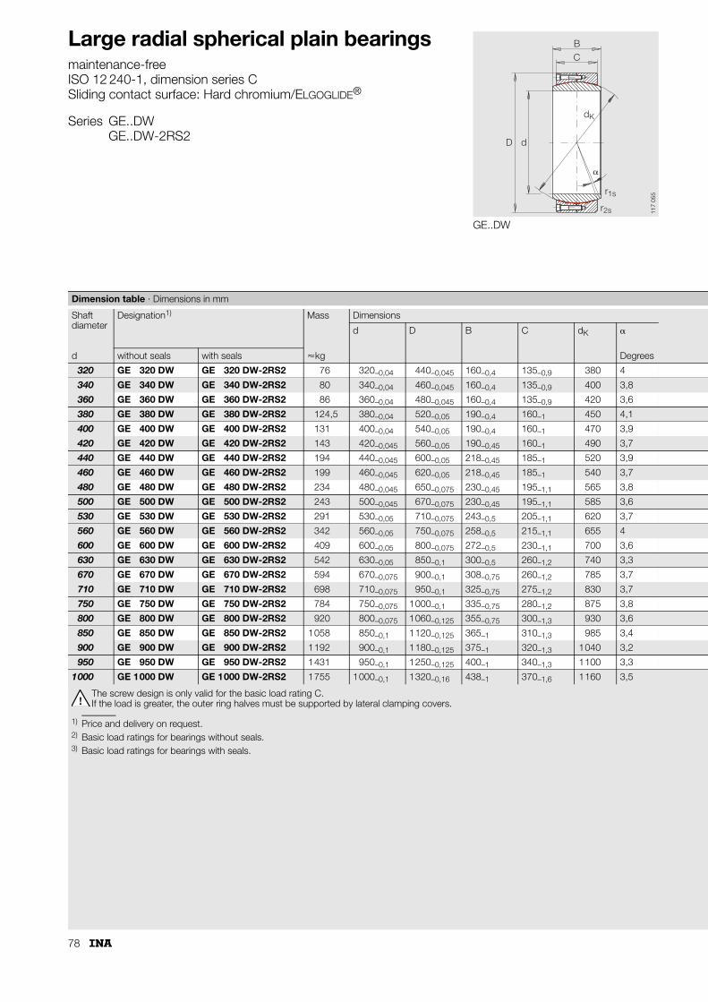
78
Large radial spherical plain bearingsmaintenance-freeISO 12 240-1, dimension series CSliding contact surface: Hard chromium/ELGOGLIDE®
Series GE..DWGE..DW-2RS2
GE..DW
BC
D d
dK
�
r1s
r2s 117
055
The screw design is only valid for the basic load rating C.If the load is greater, the outer ring halves must be supported by lateral clamping covers.
1) Price and delivery on request.2) Basic load ratings for bearings without seals.3) Basic load ratings for bearings with seals.
Dimension table · Dimensions in mm
Shaft diameter
Designation1) Mass Dimensions
d D B C dK �
d without seals with seals �kg Degrees
320 GE 320 DW GE 320 DW-2RS2 76 320–0,04 440–0,045 160–0,4 135–0,9 380 4
340 GE 340 DW GE 340 DW-2RS2 80 340–0,04 460–0,045 160–0,4 135–0,9 400 3,8
360 GE 360 DW GE 360 DW-2RS2 86 360–0,04 480–0,045 160–0,4 135–0,9 420 3,6
380 GE 380 DW GE 380 DW-2RS2 124,5 380–0,04 520–0,05 190–0,4 160–1 450 4,1
400 GE 400 DW GE 400 DW-2RS2 131 400–0,04 540–0,05 190–0,4 160–1 470 3,9
420 GE 420 DW GE 420 DW-2RS2 143 420–0,045 560–0,05 190–0,45 160–1 490 3,7
440 GE 440 DW GE 440 DW-2RS2 194 440–0,045 600–0,05 218–0,45 185–1 520 3,9
460 GE 460 DW GE 460 DW-2RS2 199 460–0,045 620–0,05 218–0,45 185–1 540 3,7
480 GE 480 DW GE 480 DW-2RS2 234 480–0,045 650–0,075 230–0,45 195–1,1 565 3,8
500 GE 500 DW GE 500 DW-2RS2 243 500–0,045 670–0,075 230–0,45 195–1,1 585 3,6
530 GE 530 DW GE 530 DW-2RS2 291 530–0,05 710–0,075 243–0,5 205–1,1 620 3,7
560 GE 560 DW GE 560 DW-2RS2 342 560–0,05 750–0,075 258–0,5 215–1,1 655 4
600 GE 600 DW GE 600 DW-2RS2 409 600–0,05 800–0,075 272–0,5 230–1,1 700 3,6
630 GE 630 DW GE 630 DW-2RS2 542 630–0,05 850–0,1 300–0,5 260–1,2 740 3,3
670 GE 670 DW GE 670 DW-2RS2 594 670–0,075 900–0,1 308–0,75 260–1,2 785 3,7
710 GE 710 DW GE 710 DW-2RS2 698 710–0,075 950–0,1 325–0,75 275–1,2 830 3,7
750 GE 750 DW GE 750 DW-2RS2 784 750–0,075 1000–0,1 335–0,75 280–1,2 875 3,8
800 GE 800 DW GE 800 DW-2RS2 920 800–0,075 1060–0,125 355–0,75 300–1,3 930 3,6
850 GE 850 DW GE 850 DW-2RS2 1058 850–0,1 1120–0,125 365–1 310–1,3 985 3,4
900 GE 900 DW GE 900 DW-2RS2 1192 900–0,1 1180–0,125 375–1 320–1,3 1040 3,2
950 GE 950 DW GE 950 DW-2RS2 1431 950–0,1 1250–0,125 400–1 340–1,3 1100 3,3
1000 GE 1000 DW GE 1000 DW-2RS2 1755 1000–0,1 1320–0,16 438–1 370–1,6 1160 3,5

79
GE..DW-2RS2 GE..DW-2RS2 – mounting dimensionsGE..DW – mounting dimensions
Detail
BC
D d
dK
�
r1s
r2s 117
214
a aD d
156
150
117
056
Chamfer dimensions Mounting dimensions Basic load ratings Radial internal clearance
Shaft diameterr1s r2s da Da dyn.2)
Cr
stat.2)
C0r
dyn.3)
Cr
stat.3)
C0r
min. min. max. min. kN kN kN kN d
1,1 3 344,6 361 15 390 25 650 12 920 21 540 0 – 0,125 320
1,1 3 366,6 382 16 200 27 000 13 600 22 680 0 – 0,125 340
1,1 3 388,3 403 17 010 28 350 14 280 23 810 0 – 0,135 360
1,5 4 407,9 426 21 600 36 000 18 680 31 140 0 – 0,135 380
1,5 4 429,8 447 22 560 37 600 19 510 32 520 0 – 0,135 400
1,5 4 451,6 469 23 520 39 200 20 340 33 900 0 – 0,135 420
1,5 4 472 491 28 860 48 100 24 490 40 820 0 – 0,145 440
1,5 4 494 513 29 970 49 950 25 430 42 390 0 – 0,145 460
2 5 516 536 33 050 55 080 28 300 47 170 0 – 0,145 480
2 5 537,8 557 34 220 57 030 29 300 48 840 0 – 0,145 500
2 5 570,3 591 38 130 63 550 32 920 54 870 0 – 0,145 530
2 5 602 624 42 240 70 410 36 740 61 240 0 – 0,16 560
2 5 644,9 667 48 300 80 500 42 420 70 700 0 – 0,16 600
3 6 676,4 698 57 720 96 200 51 500 85 840 0 – 0,16 630
3 6 722 746 61 230 102 050 54 630 91 060 0 – 0,16 670
3 6 763,7 789 68 470 114 120 60 850 101 420 0 – 0,17 710
3 6 808,3 834 73 500 122 500 65 460 109 110 0 – 0,17 750
3 6 859,5 886 83 700 139 500 75 160 125 270 0 – 0,17 800
3 6 914,8 940 91 600 152 670 82 560 137 600 0 – 0,17 850
3 6 970 995 99 840 166 400 90 290 150 480 0 – 0,17 900
4 7,5 1024,6 1052 112 200 187 000 102 100 170 170 0 – 0,17 950
4 7,5 1074,1 1105 128 760 214 600 118 110 196 850 0 – 0,195 1000

80
Radial spherical plain bearingsmaintenance-freeISO 12 240-1, dimension series GSliding contact surface: hard chromium/PTFE
Series GE..FWSliding material: PTFE composite
GE..FW-2RSSliding material: ELGOGLIDE®
GE..FW
BC
D d
dK
�
r1s
r2s
117
057
1) Price and delivery on request.
Dimension table · Dimensions in mm
Shaft diameter
Designation Mass Dimensions
d D B C dK �
d without seals with seals �kg Degrees
6 GE 6 FW1) – 0,009 6–0,008 16–0,008 9–0,12 5–0,24 13 21
8 GE 8 FW1) – 0,014 8–0,008 19–0,009 11–0,12 6–0,24 16 21
10 GE 10 FW – 0,02 10–0,008 22–0,009 12–0,12 7–0,24 18 18
12 GE 12 FW – 0,036 12–0,008 26–0,009 15–0,12 9–0,24 22 18
15 GE 15 FW – 0,049 15–0,008 30–0,009 16–0,12 10–0,24 25 16
17 GE 17 FW – 0,082 17–0,008 35–0,011 20–0,12 12–0,24 29 19
20 GE 20 FW – 0,16 20–0,01 42–0,011 25–0,12 16–0,24 35,5 17
25 GE 25 FW – 0,2 25–0,01 47–0,011 28–0,12 18–0,24 40,7 17
30 – GE 30 FW-2RS 0,28 30–0,01 55–0,013 32–0,12 20–0,3 47 17
35 – GE 35 FW-2RS 0,38 35–0,012 62–0,013 35–0,12 22–0,3 53 16
40 – GE 40 FW-2RS 0,53 40–0,012 68–0,013 40–0,12 25–0,3 60 17
45 – GE 45 FW-2RS 0,67 45–0,012 75–0,013 43–0,12 28–0,3 66 15
50 – GE 50 FW-2RS 1,4 50–0,012 90–0,015 56–0,15 36–0,4 80 17
60 – GE 60 FW-2RS 2,1 60–0,015 105–0,015 63–0,15 40–0,4 92 17
70 – GE 70 FW-2RS 3 70–0,015 120–0,015 70–0,15 45–0,4 105 16
80 – GE 80 FW-2RS 3,6 80–0,015 130–0,018 75–0,2 50–0,5 115 14
90 – GE 90 FW-2RS 5,3 90–0,02 150–0,018 85–0,2 55–0,5 130 15
100 – GE 100 FW-2RS1) 6 100–0,02 160–0,025 85–0,2 55–0,5 140 14
110 – GE 110 FW-2RS1) 9,8 110–0,02 180–0,025 100–0,2 70–0,5 160 12
120 – GE 120 FW-2RS1) 14,6 120–0,02 210–0,03 115–0,2 70–0,6 180 16
140 – GE 140 FW-2RS1) 18,6 140–0,025 230–0,03 130–0,25 80–0,6 200 16
160 – GE 160 FW-2RS1) 24,9 160–0,025 260–0,035 135–0,25 80–0,7 225 16
180 – GE 180 FW-2RS1) 33,6 180–0,025 290–0,035 155–0,3 100–0,7 250 14
200 – GE 200 FW-2RS1) 44,7 200–0,03 320–0,04 165–0,3 100–0,8 275 15
220 – GE 220 FW-2RS1) 50,8 220–0,03 340–0,04 175–0,3 100–0,8 300 16
240 – GE 240 FW-2RS1) 64 240–0,03 370–0,04 190–0,35 110–0,8 325 15
260 – GE 260 FW-2RS1) 81,8 260–0,035 400–0,04 205–0,35 120–0,8 350 15
280 – GE 280 FW-2RS1) 96,5 280–0,035 430–0,045 210–0,35 120–0,9 375 15
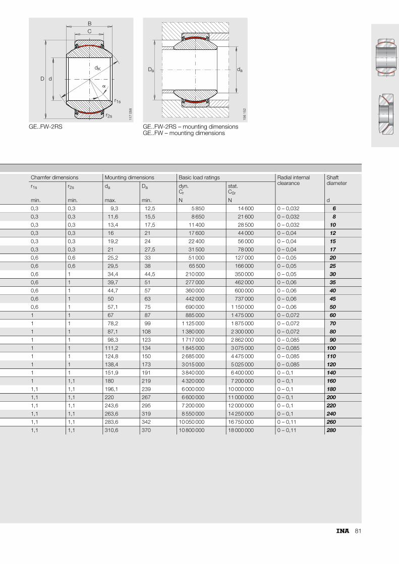
81
GE..FW-2RS GE..FW-2RS – mounting dimensionsGE..FW – mounting dimensions
BC
D d
dK
�
r1s
r2s
117
058
a aD d
156
152
Chamfer dimensions Mounting dimensions Basic load ratings Radial internal clearance
Shaftdiameterr1s r2s da Da dyn.
Cr
stat.C0r
min. min. max. min. N N d
0,3 0,3 9,3 12,5 5 850 14 600 0 – 0,032 6
0,3 0,3 11,6 15,5 8 650 21 600 0 – 0,032 8
0,3 0,3 13,4 17,5 11 400 28 500 0 – 0,032 10
0,3 0,3 16 21 17 600 44 000 0 – 0,04 12
0,3 0,3 19,2 24 22 400 56 000 0 – 0,04 15
0,3 0,3 21 27,5 31 500 78 000 0 – 0,04 17
0,6 0,6 25,2 33 51 000 127 000 0 – 0,05 20
0,6 0,6 29,5 38 65 500 166 000 0 – 0,05 25
0,6 1 34,4 44,5 210 000 350 000 0 – 0,05 30
0,6 1 39,7 51 277 000 462 000 0 – 0,06 35
0,6 1 44,7 57 360 000 600 000 0 – 0,06 40
0,6 1 50 63 442 000 737 000 0 – 0,06 45
0,6 1 57,1 75 690 000 1 150 000 0 – 0,06 50
1 1 67 87 885 000 1 475 000 0 – 0,072 60
1 1 78,2 99 1 125 000 1 875 000 0 – 0,072 70
1 1 87,1 108 1 380 000 2 300 000 0 – 0,072 80
1 1 98,3 123 1 717 000 2 862 000 0 – 0,085 90
1 1 111,2 134 1 845 000 3 075 000 0 – 0,085 100
1 1 124,8 150 2 685 000 4 475 000 0 – 0,085 110
1 1 138,4 173 3 015 000 5 025 000 0 – 0,085 120
1 1 151,9 191 3 840 000 6 400 000 0 – 0,1 140
1 1,1 180 219 4 320 000 7 200 000 0 – 0,1 160
1,1 1,1 196,1 239 6 000 000 10 000 000 0 – 0,1 180
1,1 1,1 220 267 6 600 000 11 000 000 0 – 0,1 200
1,1 1,1 243,6 295 7 200 000 12 000 000 0 – 0,1 220
1,1 1,1 263,6 319 8 550 000 14 250 000 0 – 0,1 240
1,1 1,1 283,6 342 10 050 000 16 750 000 0 – 0,11 260
1,1 1,1 310,6 370 10 800 000 18 000 000 0 – 0,11 280

82
Radial spherical plain bearingsmaintenance-freeISO 12 240-1, dimension series KSliding contact surface: Steel/PTFE-bronze film
Series GE..PW
GE..PW
BC
D d
dK
�
r1s
r2s
117
059
1) Bore tolerance: H7 (arithmetic mean value).2) Deviating from ISO 12 240-1, dimension series K.3) Price and delivery on request.
Dimension table · Dimensions in mm
Shaft diameter
Designation3) Mass Dimensions
d1) D B C dK �
d �kg Degrees
5 GE 5 PW 0,006 5+0,012 13–0,008 8–0,12 6 –0,24 11,112 13
6 GE 6 PW 0,01 6+0,012 16–0,008 9–0,12 6,75–0,24 12,7 13
8 GE 8 PW 0,019 8+0,015 19–0,009 12–0,12 9 –0,24 15,875 14
10 GE 10 PW 0,027 10+0,015 22–0,009 14–0,12 10,5 –0,24 19,05 13
12 GE 12 PW 0,043 12+0,018 26–0,009 16–0,12 12 –0,24 22,225 13
14 GE 14 PW 0,054 14+0,018 28–0,0092) 19–0,12 13,5 –0,24 25,4 16
16 GE 16 PW 0,079 16+0,018 32–0,011 21–0,12 15 –0,24 28,575 15
18 GE 18 PW 0,1 18+0,018 35–0,011 23–0,12 16,5 –0,24 31,75 15
20 GE 20 PW 0,15 20+0,021 40–0,011 25–0,12 18 –0,24 34,925 14
22 GE 22 PW 0,18 22+0,021 42–0,011 28–0,12 20 –0,24 38,1 15
25 GE 25 PW 0,24 25+0,021 47–0,011 31–0,12 22 –0,24 42,85 15
30 GE 30 PW 0,38 30+0,021 55–0,013 37–0,12 25 –0,3 50,8 17

83
GE..PW – mounting dimensions
D da a
156
153
Chamfer dimensions Mounting dimensions Basic load ratings Radial internal clearance Shaft diameterr1s r2s da Da dyn.
Cr
stat.C0r
min. min. max. min. N N d
0,3 0,3 7,7 9,8 6 000 15 000 0,006 – 0,035 5
0,3 0,3 8,9 11,5 7 650 19 300 0,006 – 0,035 6
0,3 0,3 10,3 14 12 900 32 000 0,006 – 0,035 8
0,3 0,3 12,9 17 18 000 45 000 0,006 – 0,035 10
0,3 0,3 15,4 19,5 24 000 60 000 0,006 – 0,035 12
0,3 0,3 16,8 22,5 31 000 76 500 0,006 – 0,035 14
0,3 0,3 19,3 25,5 39 000 96 500 0,006 – 0,035 16
0,3 0,3 21,8 28,5 47 500 118 000 0,006 – 0,035 18
0,3 0,6 24,3 31,5 57 000 140 000 0,006 – 0,035 20
0,3 0,6 25,8 34 68 000 170 000 0,006 – 0,035 22
0,3 0,6 29,5 38,5 85 000 212 000 0,006 – 0,035 25
0,3 0,6 34,8 46 114 000 285 000 0,006 – 0,035 30

84
Angular contact spherical plain bearingsmaintenance-freeISO 12 240-2Sliding contact surface: Hard chromium/ELGOGLIDE®
Series GE..SW
GE..SW
B
D
r
CT
s
�
dD
dK
1
r2s
r2s
1s
r1s
117
060
1) Price and delivery on request.2) Basic load ratings in radial direction.
Dimension table · Dimensions in mm
Shaft diameter
Designation Mass Dimensions
d D T dK D1 B C
d �kg
25 GE 25 SW 0,13 25–0,012 47–0,014 15�0,25 42,5 31,4 14–0,2 14–0,2
28 GE 28 SW1) 0,18 28–0,012 52–0,016 16�0,25 47 35,7 15–0,2 15–0,2
30 GE 30 SW 0,21 30–0,012 55–0,016 17�0,25 50 36,1 16–0,2 16–0,2
35 GE 35 SW 0,27 35–0,012 62–0,016 18�0,25 56 42,4 17–0,24 17–0,24
40 GE 40 SW 0,33 40–0,012 68–0,016 19�0,25 60 46,8 18–0,24 18–0,24
45 GE 45 SW 0,41 45–0,012 75–0,016 20�0,25 66 52,9 19–0,24 19–0,24
50 GE 50 SW 0,45 50–0,012 80–0,016 20�0,25 74 59,1 19–0,24 19–0,24
55 GE 55 SW1) 0,67 55–0,015 90–0,018 23�0,25 80 62 22–0,3 22–0,3
60 GE 60 SW 0,72 60–0,015 95–0,018 23�0,25 86 68,1 22–0,3 22–0,3
65 GE 65 SW1) 0,77 65–0,015 100–0,018 23�0,25 92 75,6 22–0,3 22–0,3
70 GE 70 SW 1 70–0,015 110–0,018 25�0,25 102 82,2 24–0,3 24–0,3
80 GE 80 SW 1,5 80–0,015 125–0,02 29�0,25 115 90,5 27–0,3 27–0,3
90 GE 90 SW 2,1 90–0,02 140–0,02 32�0,25 130 103,3 30–0,4 30–0,4
100 GE 100 SW 2,3 100–0,02 150–0,02 32�0,25 140 114,3 30–0,4 30–0,4
110 GE 110 SW1) 3,7 110–0,02 170–0,025 38�0,25 160 125,8 36–0,4 36–0,4
120 GE 120 SW 3,9 120–0,02 180–0,025 38�0,25 170 135,4 36–0,4 36–0,4
130 GE 130 SW1) 6,1 130–0,025 200–0,03 45�0,35 190 148 42–0,5 42–0,5
140 GE 140 SW1) 6,4 140–0,025 210–0,03 45�0,35 200 160,6 42–0,5 42–0,5
150 GE 150 SW1) 7,8 150–0,025 225–0,03 48�0,35 213 170,9 45–0,5 45–0,5
160 GE 160 SW1) 9,5 160–0,025 240–0,03 51�0,35 225 181,4 48–0,5 48–0,5
170 GE 170 SW1) 13 170–0,025 260–0,035 57�0,35 250 194,3 54–0,5 54–0,5
180 GE 180 SW1) 17,4 180–0,025 280–0,035 64�0,35 260 205,5 61–0,5 61–0,5
190 GE 190 SW1) 18,2 190–0,03 290–0,035 64�0,35 275 211,8 61–0,6 61–0,6
200 GE 200 SW1) 23,3 200–0,03 310–0,035 70�0,35 290 229,2 66–0,6 66–0,6
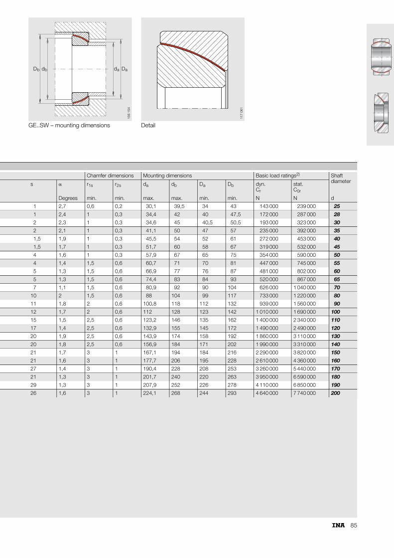
85
GE..SW – mounting dimensions Detail
b bD d a aDd
156
154
117
061
Chamfer dimensions Mounting dimensions Basic load ratings2) Shaft diameters � r1s r2s da db Da Db dyn.
Cr
stat.C0r
Degrees min. min. max. max. min. min. N N d
1 2,7 0,6 0,2 30,1 39,5 34 43 143 000 239 000 25
1 2,4 1 0,3 34,4 42 40 47,5 172 000 287 000 28
2 2,3 1 0,3 34,6 45 40,5 50,5 193 000 323 000 30
2 2,1 1 0,3 41,1 50 47 57 235 000 392 000 35
1,5 1,9 1 0,3 45,5 54 52 61 272 000 453 000 40
1,5 1,7 1 0,3 51,7 60 58 67 319 000 532 000 45
4 1,6 1 0,3 57,9 67 65 75 354 000 590 000 50
4 1,4 1,5 0,6 60,7 71 70 81 447 000 745 000 55
5 1,3 1,5 0,6 66,9 77 76 87 481 000 802 000 60
5 1,3 1,5 0,6 74,4 83 84 93 520 000 867 000 65
7 1,1 1,5 0,6 80,9 92 90 104 626 000 1 040 000 70
10 2 1,5 0,6 88 104 99 117 733 000 1 220 000 80
11 1,8 2 0,6 100,8 118 112 132 939 000 1 560 000 90
12 1,7 2 0,6 112 128 123 142 1 010 000 1 690 000 100
15 1,5 2,5 0,6 123,2 146 135 162 1 400 000 2 340 000 110
17 1,4 2,5 0,6 132,9 155 145 172 1 490 000 2 490 000 120
20 1,9 2,5 0,6 143,9 174 158 192 1 860 000 3 110 000 130
20 1,8 2,5 0,6 156,9 184 171 202 1 990 000 3 310 000 140
21 1,7 3 1 167,1 194 184 216 2 290 000 3 820 000 150
21 1,6 3 1 177,7 206 195 228 2 610 000 4 360 000 160
27 1,4 3 1 190,4 228 208 253 3 260 000 5 440 000 170
21 1,3 3 1 201,7 240 220 263 3 950 000 6 590 000 180
29 1,3 3 1 207,9 252 226 278 4 110 000 6 850 000 190
26 1,6 3 1 224,1 268 244 293 4 640 000 7 740 000 200
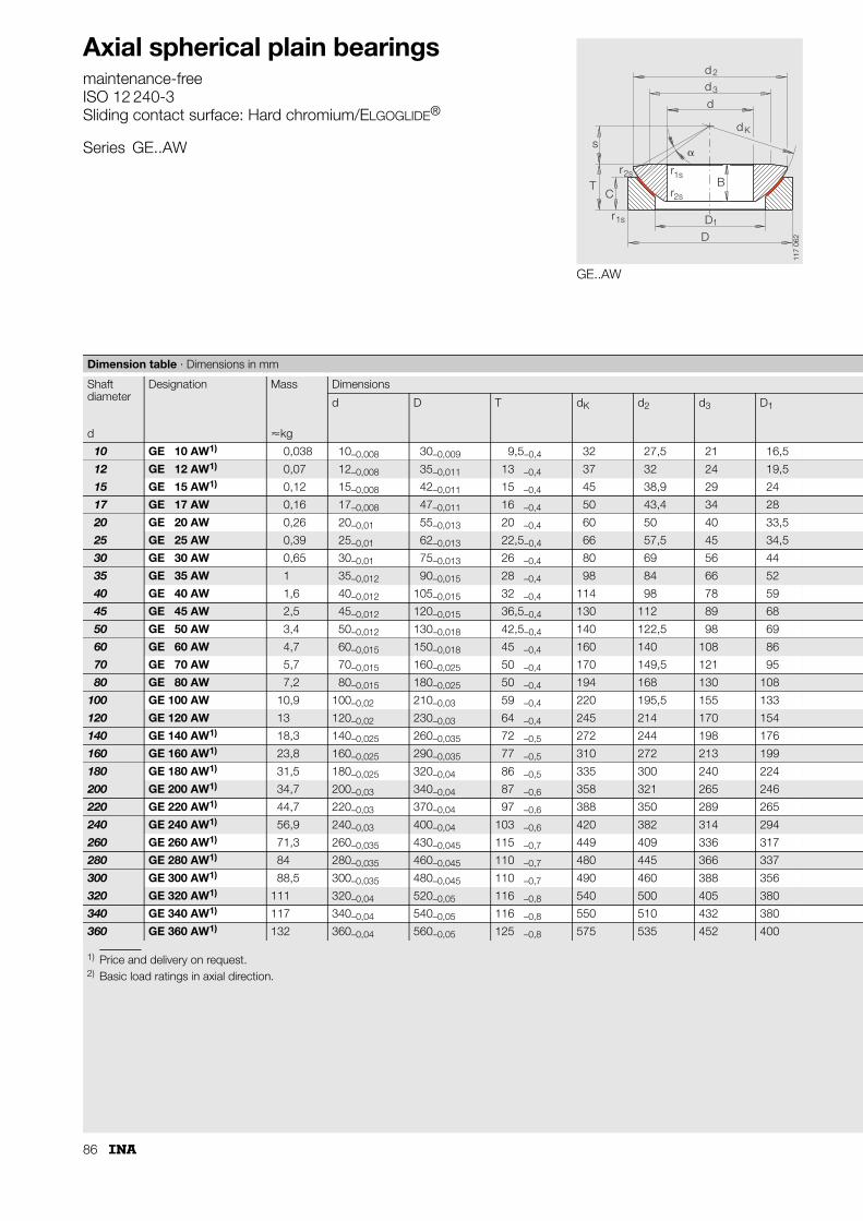
86
Axial spherical plain bearingsmaintenance-freeISO 12 240-3Sliding contact surface: Hard chromium/ELGOGLIDE®
Series GE..AW
GE..AW
dd
d
s
Tr
CB
r
r
DD
�
3
dK
2
2s
r1s
1s
2s
1
117
062
1) Price and delivery on request.2) Basic load ratings in axial direction.
Dimension table · Dimensions in mm
Shaft diameter
Designation Mass Dimensions
d D T dK d2 d3 D1
d �kg
10 GE 10 AW1) 0,038 10–0,008 30–0,009 9,5–0,4 32 27,5 21 16,5
12 GE 12 AW1) 0,07 12–0,008 35–0,011 13 –0,4 37 32 24 19,5
15 GE 15 AW1) 0,12 15–0,008 42–0,011 15 –0,4 45 38,9 29 24
17 GE 17 AW 0,16 17–0,008 47–0,011 16 –0,4 50 43,4 34 28
20 GE 20 AW 0,26 20–0,01 55–0,013 20 –0,4 60 50 40 33,5
25 GE 25 AW 0,39 25–0,01 62–0,013 22,5–0,4 66 57,5 45 34,5
30 GE 30 AW 0,65 30–0,01 75–0,013 26 –0,4 80 69 56 44
35 GE 35 AW 1 35–0,012 90–0,015 28 –0,4 98 84 66 52
40 GE 40 AW 1,6 40–0,012 105–0,015 32 –0,4 114 98 78 59
45 GE 45 AW 2,5 45–0,012 120–0,015 36,5–0,4 130 112 89 68
50 GE 50 AW 3,4 50–0,012 130–0,018 42,5–0,4 140 122,5 98 69
60 GE 60 AW 4,7 60–0,015 150–0,018 45 –0,4 160 140 108 86
70 GE 70 AW 5,7 70–0,015 160–0,025 50 –0,4 170 149,5 121 95
80 GE 80 AW 7,2 80–0,015 180–0,025 50 –0,4 194 168 130 108
100 GE 100 AW 10,9 100–0,02 210–0,03 59 –0,4 220 195,5 155 133
120 GE 120 AW 13 120–0,02 230–0,03 64 –0,4 245 214 170 154
140 GE 140 AW1) 18,3 140–0,025 260–0,035 72 –0,5 272 244 198 176
160 GE 160 AW1) 23,8 160–0,025 290–0,035 77 –0,5 310 272 213 199
180 GE 180 AW1) 31,5 180–0,025 320–0,04 86 –0,5 335 300 240 224
200 GE 200 AW1) 34,7 200–0,03 340–0,04 87 –0,6 358 321 265 246
220 GE 220 AW1) 44,7 220–0,03 370–0,04 97 –0,6 388 350 289 265
240 GE 240 AW1) 56,9 240–0,03 400–0,04 103 –0,6 420 382 314 294
260 GE 260 AW1) 71,3 260–0,035 430–0,045 115 –0,7 449 409 336 317
280 GE 280 AW1) 84 280–0,035 460–0,045 110 –0,7 480 445 366 337
300 GE 300 AW1) 88,5 300–0,035 480–0,045 110 –0,7 490 460 388 356
320 GE 320 AW1) 111 320–0,04 520–0,05 116 –0,8 540 500 405 380
340 GE 340 AW1) 117 340–0,04 540–0,05 116 –0,8 550 510 432 380
360 GE 360 AW1) 132 360–0,04 560–0,05 125 –0,8 575 535 452 400
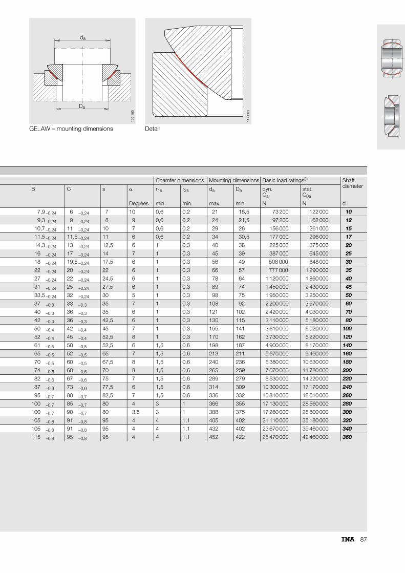
87
GE..AW – mounting dimensions Detail
d
Da
a
156
155
117
063
Chamfer dimensions Mounting dimensions Basic load ratings2) Shaft diameterB C s � r1s r2s da Da dyn.
Ca
stat.C0a
Degrees min. min. max. min. N N d
7,9 –0,24 6 –0,24 7 10 0,6 0,2 21 18,5 73 200 122 000 10
9,3 –0,24 9 –0,24 8 9 0,6 0,2 24 21,5 97 200 162 000 12
10,7 –0,24 11 –0,24 10 7 0,6 0,2 29 26 156 000 261 000 15
11,5 –0,24 11,5 –0,24 11 6 0,6 0,2 34 30,5 177 000 296 000 17
14,3 –0,24 13 –0,24 12,5 6 1 0,3 40 38 225 000 375 000 20
16 –0,24 17 –0,24 14 7 1 0,3 45 39 387 000 645 000 25
18 –0,24 19,5 –0,24 17,5 6 1 0,3 56 49 508 000 848 000 30
22 –0,24 20 –0,24 22 6 1 0,3 66 57 777 000 1 290 000 35
27 –0,24 22 –0,24 24,5 6 1 0,3 78 64 1 120 000 1 860 000 40
31 –0,24 25 –0,24 27,5 6 1 0,3 89 74 1 450 000 2 430 000 45
33,5 –0,24 32 –0,24 30 5 1 0,3 98 75 1 950 000 3 250 000 50
37 –0,3 33 –0,3 35 7 1 0,3 108 92 2 200 000 3 670 000 60
40 –0,3 36 –0,3 35 6 1 0,3 121 102 2 420 000 4 030 000 70
42 –0,3 36 –0,3 42,5 6 1 0,3 130 115 3 110 000 5 180 000 80
50 –0,4 42 –0,4 45 7 1 0,3 155 141 3 610 000 6 020 000 100
52 –0,4 45 –0,4 52,5 8 1 0,3 170 162 3 730 000 6 220 000 120
61 –0,5 50 –0,5 52,5 6 1,5 0,6 198 187 4 900 000 8 170 000 140
65 –0,5 52 –0,5 65 7 1,5 0,6 213 211 5 670 000 9 460 000 160
70 –0,5 60 –0,5 67,5 8 1,5 0,6 240 236 6 380 000 10 630 000 180
74 –0,6 60 –0,6 70 8 1,5 0,6 265 259 7 070 000 11 780 000 200
82 –0,6 67 –0,6 75 7 1,5 0,6 289 279 8 530 000 14 220 000 220
87 –0,6 73 –0,6 77,5 6 1,5 0,6 314 309 10 300 000 17 170 000 240
95 –0,7 80 –0,7 82,5 7 1,5 0,6 336 332 10 810 000 18 010 000 260
100 –0,7 85 –0,7 80 4 3 1 366 355 17 130 000 28 560 000 280
100 –0,7 90 –0,7 80 3,5 3 1 388 375 17 280 000 28 800 000 300
105 –0,8 91 –0,8 95 4 4 1,1 405 402 21 110 000 35 180 000 320
105 –0,8 91 –0,8 95 4 4 1,1 432 402 23 670 000 39 460 000 340
115 –0,8 95 –0,8 95 4 4 1,1 452 422 25 470 000 42 460 000 360
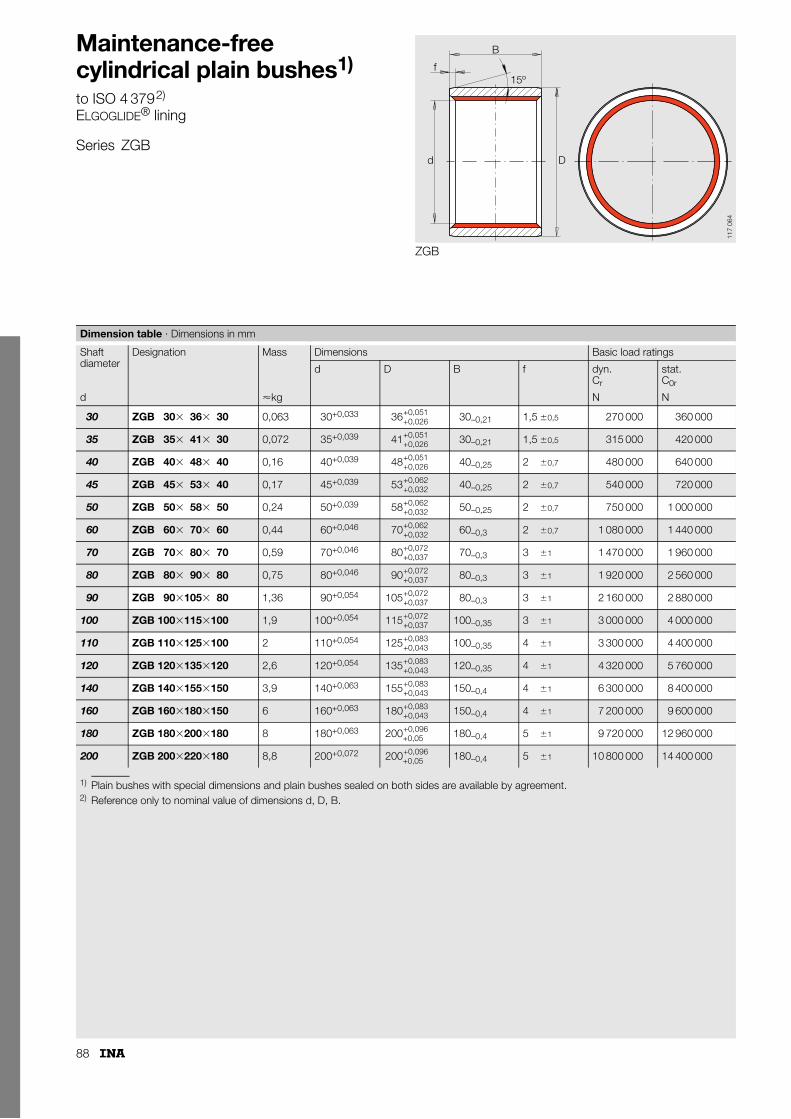
88
Maintenance-free cylindrical plain bushes1)
to ISO 4 3792)
ELGOGLIDE® lining
Series ZGB
ZGB
B
f15º
d D
117
064
1) Plain bushes with special dimensions and plain bushes sealed on both sides are available by agreement.2) Reference only to nominal value of dimensions d, D, B.
Dimension table · Dimensions in mm
Shaft diameter
Designation Mass Dimensions Basic load ratings
d D B f dyn.Cr
stat.C0r
d �kg N N
30 ZGB 30� 36� 30 0,063 30+0,033 30–0,21 1,5 �0,5 270 000 360 000
35 ZGB 35� 41� 30 0,072 35+0,039 30–0,21 1,5 �0,5 315 000 420 000
40 ZGB 40� 48� 40 0,16 40+0,039 40–0,25 2 �0,7 480 000 640 000
45 ZGB 45� 53� 40 0,17 45+0,039 40–0,25 2 �0,7 540 000 720 000
50 ZGB 50� 58� 50 0,24 50+0,039 50–0,25 2 �0,7 750 000 1 000 000
60 ZGB 60� 70� 60 0,44 60+0,046 60–0,3 2 �0,7 1 080 000 1 440 000
70 ZGB 70� 80� 70 0,59 70+0,046 70–0,3 3 �1 1 470 000 1 960 000
80 ZGB 80� 90� 80 0,75 80+0,046 80–0,3 3 �1 1 920 000 2 560 000
90 ZGB 90�105� 80 1,36 90+0,054 80–0,3 3 �1 2 160 000 2 880 000
100 ZGB 100�115�100 1,9 100+0,054 100–0,35 3 �1 3 000 000 4 000 000
110 ZGB 110�125�100 2 110+0,054 100–0,35 4 �1 3 300 000 4 400 000
120 ZGB 120�135�120 2,6 120+0,054 120–0,35 4 �1 4 320 000 5 760 000
140 ZGB 140�155�150 3,9 140+0,063 150–0,4 4 �1 6 300 000 8 400 000
160 ZGB 160�180�150 6 160+0,063 150–0,4 4 �1 7 200 000 9 600 000
180 ZGB 180�200�180 8 180+0,063 180–0,4 5 �1 9 720 000 12 960 000
200 ZGB 200�220�180 8,8 200+0,072 180–0,4 5 �1 10 800 000 14 400 000
36+0,051+0,026
41+0,051+0,026
48+0,051+0,026
53+0,062+0,032
58+0,062+0,032
70+0,062+0,032
80+0,072+0,037
90+0,072+0,037
105+0,072+0,037
115+0,072+0,037
125+0,083+0,043
135+0,083+0,043
155+0,083+0,043
180+0,083+0,043
200+0,096+0,05
200+0,096+0,05

89
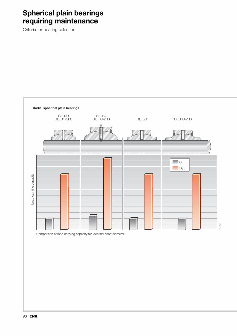
90
Spherical plain bearings requiring maintenanceCriteria for bearing selection
GE..DOGE..DO-2RS
GE..FOGE..FO-2RS GE..LO GE..HO-2RS
C
C0r
r
Comparison of load carrying capacity for identical shaft diameter.
Load
car
ryin
g ca
paci
ty
Radial spherical plain bearings
117
100

91
GE..SXGE..PB GE..ZO
C
C0r
r
Angular contactspherical plain bearings
Axial sphericalplain bearings
Load
car
ryin
g ca
paci
ty
Ca
C0a
117
120
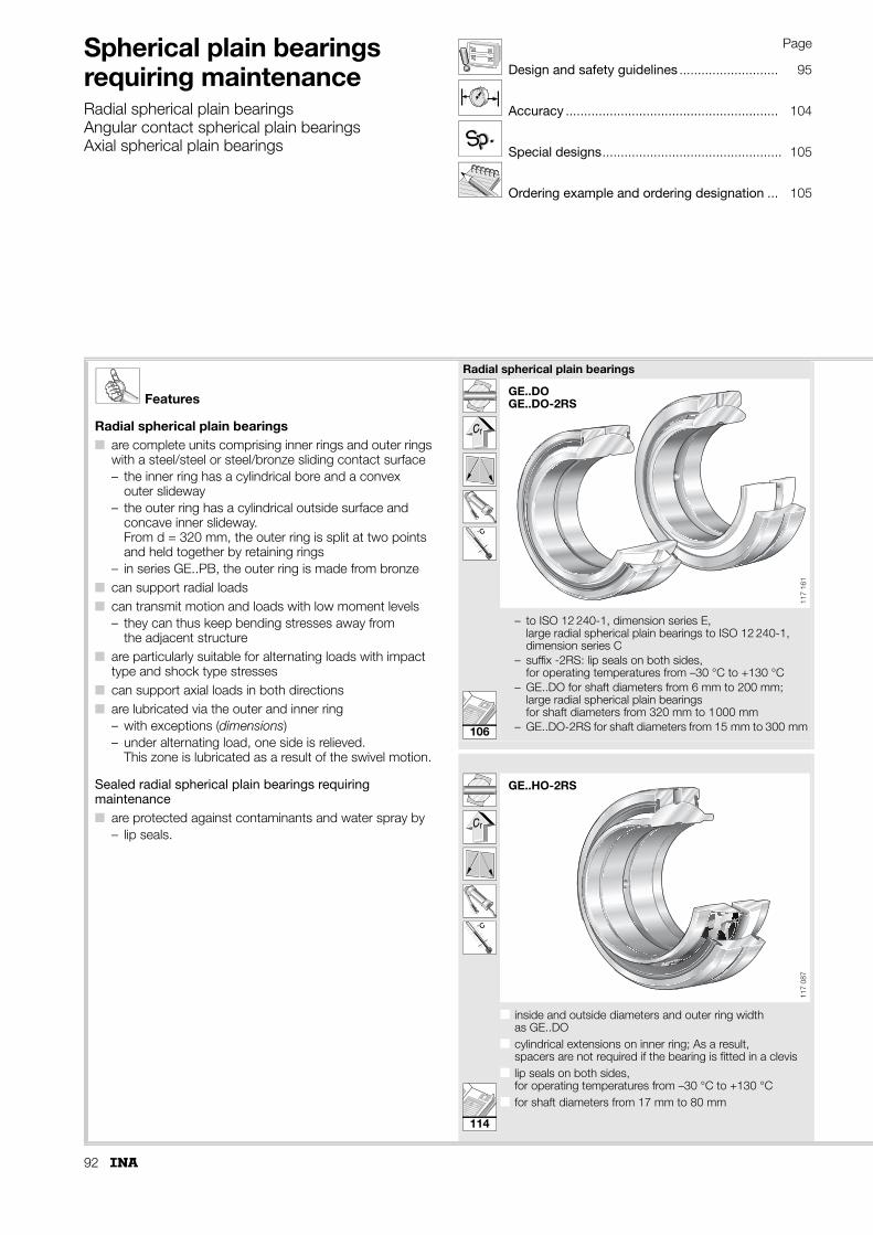
92
Spherical plain bearings requiring maintenanceRadial spherical plain bearingsAngular contact spherical plain bearingsAxial spherical plain bearings
Page
Design and safety guidelines ........................... 95
Accuracy .......................................................... 104
Special designs................................................. 105
Ordering example and ordering designation ... 105
p.p.SS
Features
Radial spherical plain bearings■ are complete units comprising inner rings and outer rings
with a steel/steel or steel/bronze sliding contact surface– the inner ring has a cylindrical bore and a convex
outer slideway– the outer ring has a cylindrical outside surface and
concave inner slideway. From d = 320 mm, the outer ring is split at two points and held together by retaining rings
– in series GE..PB, the outer ring is made from bronze■ can support radial loads■ can transmit motion and loads with low moment levels
– they can thus keep bending stresses away from the adjacent structure
■ are particularly suitable for alternating loads with impact type and shock type stresses
■ can support axial loads in both directions■ are lubricated via the outer and inner ring
– with exceptions (dimensions)– under alternating load, one side is relieved.
This zone is lubricated as a result of the swivel motion.
Sealed radial spherical plain bearings requiring maintenance■ are protected against contaminants and water spray by
– lip seals.
Radial spherical plain bearings
˚C
– to ISO 12 240-1, dimension series E, large radial spherical plain bearings to ISO 12 240-1, dimension series C
– suffix -2RS: lip seals on both sides, for operating temperatures from –30 °C to +130 °C
– GE..DO for shaft diameters from 6 mm to 200 mm; large radial spherical plain bearings for shaft diameters from 320 mm to 1000 mm
– GE..DO-2RS for shaft diameters from 15 mm to 300 mm
˚C
■ inside and outside diameters and outer ring width as GE..DO
■ cylindrical extensions on inner ring; As a result, spacers are not required if the bearing is fitted in a clevis
■ lip seals on both sides, for operating temperatures from –30 °C to +130 °C
■ for shaft diameters from 17 mm to 80 mm
GE..DOGE..DO-2RS
117
161
GE..HO-2RS11
7 08
7
106
114

93
˚C
˚C
■ to ISO 12 240-1, dimension series G■ larger tilt angle � due to wider inner ring■ suffix -2RS: lip seals on both sides,
for operating temperatures from –30 °C to +130 °C■ GE..FO for shaft diameters from 6 mm to 12 mm■ GE..FO-2RS for shaft diameters from 15 mm to 280 mm
■ to ISO 12 240-1, dimension series W■ bore dimensions to standard sizes,
dimensions to DIN 24 338 for standard hydraulic cylinders■ for shaft diameters from 12 mm to 320 mm■ bore nominal dimension identical to inner ring width
nominal dimension■ d = 320,
classified as large radial spherical plain bearings
■ ■
˚C ˚C
■ inch sizes■ for shaft diameters from 0,75 inches (19,05 mm)
to 3 inches (76,2 mm)
■ to ISO 12 240-1, dimension series K■ steel/bronze sliding contact surface■ for shaft diameters from 5 mm to 30 mm
GE..FOGE..FO-2RS
117
162
GE..LO
117
086
GE..ZO
117
088
GE..PB11
7 08
5
112
118
110
116

94
Spherical plain bearings requiring maintenance
Angular contact spherical plain bearingsAxial spherical plain bearings
Page
Design and safety guidelines ........................... 95
Accuracy .......................................................... 104
Special designs................................................. 105
Ordering example and ordering designation ... 105
p.p.SS
Features
Angular contact spherical plain bearings■ are complete units comprising an inner ring and
an outer ring with a steel/steel sliding contact surface– the inner ring has a convex outer slideway– the outer ring has a concave inner slideway
■ can support axial loads as well as radial loads– they are thus suitable for alternating dynamic loads
■ are used, for example, where loads acting in conjunction with small swivel angles would damage rolling element bearings– they are a plain bearing alternative to tapered roller
bearings of series 320 X to DIN 720■ can transmit motion and loads with low moment levels
– they can thus keep bending stresses away from the adjacent structure
■ are designed as standard for grease lubrication– are lubricated via the outer ring.
Axial spherical plain bearings■ are complete units comprising shaft locating and housing
locating washers with a steel/steel sliding contact surface– the shaft locating washer is supported in the ball
socket-shaped sliding zone of the housing locating washer
■ can support axial loads■ can transmit support loads into the adjacent construction
with low moment levels■ can be combined with radial spherical plain bearings
of dimension series E to ISO 12 240-1– in order to support radial loads
■ are lubricated via the housing locating washer.
Angular contact spherical plain bearings
■ to ISO 12 240-2■ for shaft diameters from 25 mm to 200 mm
Axial spherical plain bearings
■ to ISO 12 240-3■ for shaft diameters from 10 mm to 200 mm
GE..SX
117
089
GE..AX11
7 09
0
120
122

95
Design and safety guidelinesNote the ratio Cr (Ca)/P (Predimensioning, page 22 and Table 1). The permissible ratio is decisively dependent on the operating conditions, lubricant and the required operating life.
The parts of different bearings are not interchangeable with each other.The relubrication intervals must be observed.If oil lubrication is to be used, the bearings must be provided with different lubrication groove systems (suffix F10, page 13).If fitting is carried out with the aid of refrigeration by means of dry ice or liquid nitrogen, the material may undergo a volume increase that may eliminate the bearing clearance in certain circumstances.
Angular contact spherical plain bearingsIf angular contact spherical plain bearings are to transmit axial and radial loads, the bearings can be installed in pairs in an O or X arrangement (Figure 1 and Figure 2).The precondition is: axial clearance (0,1 � 0,05 mm).
Figure 1 · Bearings in pairs – O arrangement
Figure 2 · Bearings in pairs – X arrangement
Table 1 · Ratio Cr (Ca)/P for spherical plain bearings requiring maintenance under dynamic load – guide values
Series Alternating loadCr (Ca)/P
Unilateral loadCr (Ca)/P
GE..DOGE..DO-2RSGE..FOGE..FO-2RS
3 to 1 4 to 1,7
GE..PB 3 to 1 4 to 1
GE..LOGE..HO-2RSGE..ZO
3 to 1 4 to 1,7
GE..SX 3 to 1,5 4 to 2
GE..AX – 4 to 2
117
105
117
107

96
Spherical plain bearings requiring maintenance
Radial spherical plain bearingsAngular contact spherical plain bearingsAxial spherical plain bearings
Axial spherical plain bearingsIf axial spherical plain bearings are to be combined with radial spherical plain bearings of dimension series E to ISO 12 240-1 in order to support radial loads, the axial and radial load must be distributed over both bearings.In order to achieve this:■ the pin must have a radial release of approx. 1 mm in
the shaft locating washer (Figure 3) or ■ the pin must only be in contact with the large end surface of
the shaft locating washer (Figure 3).
Further information PageLoad carrying capacity and life ............................. 17Friction ................................................................. 26Lubrication ........................................................... 28Internal clearance and operating clearance........... 30Design of bearing arrangements........................... 37Sealing ................................................................. 40Fitting and dismantling ......................................... 42Operating temperatures ....................................... 47Materials .............................................................. 48ISO tolerances ..................................................... 51 Figure 3 · Combination of axial
and radial spherical plain bearing
F
FddK
dd K
1mm
R
FR
117 212
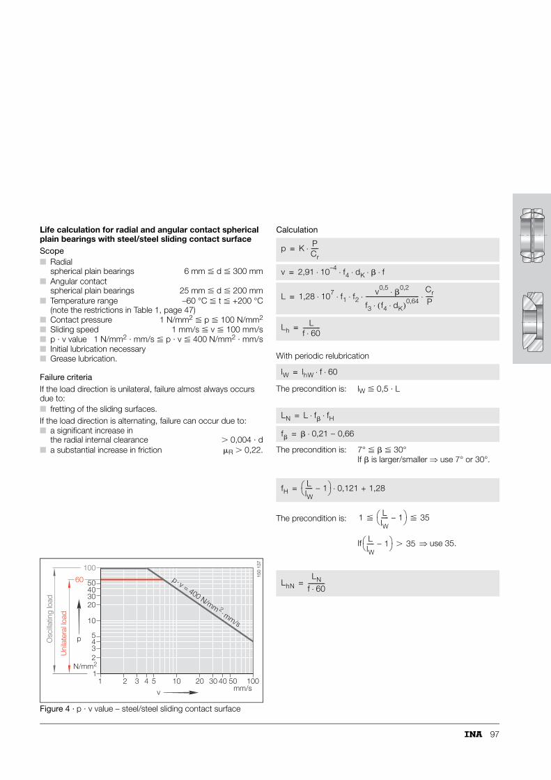
97
Life calculation for radial and angular contact spherical plain bearings with steel/steel sliding contact surfaceScope
Failure criteriaIf the load direction is unilateral, failure almost always occurs due to:■ fretting of the sliding surfaces.If the load direction is alternating, failure can occur due to:
Figure 4 · p · v value – steel/steel sliding contact surface
Calculation
With periodic relubrication
■ Radial spherical plain bearings 6 mm � d � 300 mm
■ Angular contact spherical plain bearings 25 mm � d � 200 mm
■ Temperature range –60 °C � t � +200 °C(note the restrictions in Table 1, page 47)
■ Contact pressure 1 N/mm2 � p � 100 N/mm2
■ Sliding speed 1 mm/s � v � 100 mm/s■ p · v value 1 N/mm2 · mm/s � p · v � 400 N/mm2 · mm/s■ Initial lubrication necessary■ Grease lubrication.
■ a significant increase in the radial internal clearance � 0,004 · d
■ a substantial increase in friction �R � 0,22.
1 2 3 4 5 10 20 30 40 50 100mm/s
1
2345
10
20304050
100
N/mm2
v
p
Uni
late
ral l
oad
Osc
illatin
g lo
ad
60 p v = 400 N/mm mm/s
.
2.
150
137
The precondition is: lW � 0,5 · L
The precondition is: 7° � � � 30°If � is larger/smaller ⇒ use 7° or 30°.
The precondition is:
If ⇒ use 35.
p K PCr-----⋅=
v 2,91 10–4 f4 dK � f⋅ ⋅ ⋅ ⋅ ⋅=
L 1,28 107 f1 f2v0,5
�0,2⋅
f3 f4 dK⋅( )0,64⋅--------------------------------------
Cr
P-----⋅ ⋅ ⋅ ⋅ ⋅=
LhL
f 60⋅------------=
lW lhW f 60⋅ ⋅=
LN L f� fH⋅ ⋅=
f� � 0,21 – 0,66⋅=
fHLlW----- – 1⎝ ⎠⎛ ⎞ 0,121 + 1,28⋅=
1 � LlW----- – 1⎝ ⎠⎛ ⎞ � 35
LlW----- – 1⎝ ⎠⎛ ⎞ � 35
LhNLN
f 60⋅------------=

98
Spherical plain bearings requiring maintenance
Radial spherical plain bearingsAngular contact spherical plain bearingsAxial spherical plain bearings
Life calculation for steel/bronze sliding contact surfaceScope
Failure criteriaIf the load direction is unilateral, failure almost always occurs due to:■ fretting of the sliding surfaces.If the load direction is alternating, failure can occur due to:
Figure 5 · p · v value – steel/bronze sliding contact surface
Calculation
With periodic relubrication
■ Radial spherical plain bearings 5 mm � d � 30 mm
■ Temperature range –60 °C � t � +250 °C■ Contact pressure 1 N/mm2 � p � 50 N/mm2
■ Sliding speed 1 mm/s � v � 100 mm/s■ p · v value 1 N/mm2 · mm/s � p · v � 400 N/mm2 · mm/s■ Initial lubrication necessary■ Grease lubrication.
■ a significant increase inthe radial internal clearance � 0,004 · d
■ a substantial increase in friction �R � 0,25.
1 2 3 4 5 10 20 30 40 50 100mm/s
1
2345
10
20
304050
N/mm 2
p v = 400 N/mm mm/s
.
2.
v
p
150
138
The precondition is: lW � 0,5 · L
The precondition is: 5° � � � 60°If � is larger/smaller ⇒ use 5° or 60°.
The precondition is:
If ⇒ use 20.
p K PCr-----⋅=
v 2,91 10–4 dK � f⋅ ⋅ ⋅ ⋅=
L 1,4 108 f1 f2 v0,2⋅ ⋅
f3 dK �⋅( )0,8⋅-----------------------------------
Cr
P-----⋅ ⋅ ⋅=
LhL
f 60⋅------------=
lW lhW f 60⋅ ⋅=
LN L f� fH⋅ ⋅=
f� � 0,055 + 0,727⋅=
fHLlW----- – 1⎝ ⎠⎛ ⎞ 0,14 + 1,26⋅=
1 � LlW----- – 1⎝ ⎠⎛ ⎞ � 20
LlW----- – 1⎝ ⎠⎛ ⎞ � 20
LhNLN
f 60⋅------------=

99
Symbols, units and definitionsp N/mm2
Specific bearing load, contact pressure
P NEquivalent bearing load
Cr NBasic dynamic load rating of bearing (dimension table)
K N/mm2
Basic load rating factor (Table 2)
v mm/sMean sliding speed
dK mmSphere diameter (dimension table)
� °Swivel or oscillation angle(from end position to end position, for rotary motion � = 180°, see page 24 and 25; use � = �1)
f min–1
Oscillation frequency or speed
f1 –Load direction factor (Table 2)
f2 –Temperature factor (Table 2)
f3 –Load factor (Table 2)
f4 –Bearing design factor (Table 2)
L oscillationsTheoretical life with single initial lubrication
Lh hTheoretical life with single initial lubrication
LN oscillationsTheoretical life with periodic relubrication
LhN hTheoretical life with periodic relubrication
lW oscillationsMaintenance interval between two lubrication operations
lhW hMaintenance interval between two lubrication operations
f� –Relubrication factor, dependent on �
fH –Relubrication factor, dependent on frequency.
Table 2 · Factors for life calculation
Sliding contact surface
Basic load rating factor
Load direction factor Temperature factor Load factor Bearing design factor
K f1 f2 f3 f4
N/mm2
Unilateral load
Alternating load
t � 150 °C
t� 150 °C to 180 °C
t� 180 °C to 200 °C
t� 200 °C to 250 °C
p = 1 – 12,5
p = � 12,5 – 50
p = � 50 – 100
Radial spherical plain bearings
Angular contact spherical plain bearings
Steel/steel 100 1 2 1 0,9 0,7 – 42 p1,48 p1,48 1 0,9
Steel/bronze 50 1 2 1 0,9 0,8 0,5 4,6 p0,6 – – –

100
Spherical plain bearings requiring maintenance
Radial spherical plain bearingsAngular contact spherical plain bearingsAxial spherical plain bearings
Calculation example for steel/steel sliding contact surfaceGivenPivot of a linkage rod.
Operating parameters:
Bearing data:
RequiredMinimum life of 12 000 h.
Calculation
X (Figure 4, page 18) ⇒ = 1,807 orX = 0,978 · 21,546Fa/Fr = 0,978 · 21,5460,2 = 1,807P = 1,807 · 25 kN = 45,18 kN
v = 2,91 · 10–4 · 1 · 66 · 35 · 6 = 4,033 mm/s
L = 169 920 osc.
lW = 16 · 6 · 60 = 5 760 osc.
� � 30° ⇒ use 30°f� = 30 · 0,21 – 0,66 = 5,64
LN = 169 920 · 5,64 · 4,728 = 4 527 830 osc.
LhN = 12 577 h �12 000 h required
Bearing load FRFA
==
25 kN5 kN
Swivel angle � = 35°Swivel frequency f = 6 min–1
Maintenance interval lhW = 16 hAmbient temperature = –20 °C to +60 °C
Radial spherical plain bearings = GE 50 DO■ Basic dynamic load rating■ Sphere diameter
CrdK
==
156 kN66 mm
Basic load rating factor (Table 2) K = 100 N/mm2
Load direction factor (Table 2) f1 = 2■ Alternating loadTemperature factor (Table 2) f2 = 1Bearing design factor (Table 2) f4 = 1■ for radial spherical plain bearings
P X FR⋅=
FA
FR------ 5 kN
25 kN--------------- 0,2= =
p K PCr-----⋅=
p 100 45,18156
---------------⋅ 28,96 N/mm2= =
The precondition is: lW � 0,5 L is fulfilled
v 2,91 10–4 f4 dK � f⋅ ⋅ ⋅ ⋅ ⋅=
L 1,28 107 f1 f2v0,5
�0,2⋅
f3 f4 dK⋅( )0,64⋅--------------------------------------
Cr
P-----⋅ ⋅ ⋅ ⋅ ⋅=
L 1,28 107 2 1 4,0330,5 350,2⋅
28,961,48 1 66⋅( )0,64⋅--------------------------------------------------------- 156
45,18---------------⋅ ⋅ ⋅ ⋅ ⋅=
lW lhW f 60⋅ ⋅=
f� � 0,21 – 0,66⋅=
fHLlW----- – 1⎝ ⎠⎛ ⎞ 0,121 + 1,28⋅=
fH169 920
5 760--------------------- –1⎝ ⎠⎛ ⎞ 0,121 + 1,28⋅ 4,728= =
LN L f� fH⋅ ⋅=
LhNLN
f 60⋅------------=
LhN4 527 830
6 60⋅------------------------- 12 577 h= =

101
Calculation example for steel/bronze sliding contact surfaceGivenIndexing plate for indexing station on a packaging line.
Operating parameters:
Bearing data:
Operating duration:
3 s/cycle gives 20 cycles/min with 100% utilisation 300 cycles/h gives 5 cycles/min
Required
Calculation
v = 2,91 · 10–4 · 42,9 · 45 · 20 = 11,24 mm/s
p · v = 25,31 N/mm2 · 11,24 mm/sp · v = 284,5 N/mm2 · mm/sp · v � 400 N/mm2, condition fulfilled
L = 151993 oscillations with single initial lubrication
Influence of relubrication
lW = 40 · 20 · 60 · 0,25 = 12 000 osc.lW � 0,5 · L, condition fulfilled
f� = 45 · 0,055 +0,727 = 3,2
fH = 2,89
LN = 151 993 · 3,2 · 2,89 = 1405 631 osc.
LhN = 4 685 h �4 000 h required.
Bearing load FR minFR max
==
16 kN30 kN
Swivel angle � = 45°Time required for indexing operation = 3 secSwivel frequency f = 20 min–1
■ required for calculating the mean sliding speed within one motion cycle
Maintenance interval lhW = 40 h
Radial spherical plain bearings = GE 25 PBBasic dynamic load rating Cr = 47,5 kNSphere diameter dK = 42,9 mmLoad direction factor for unilateral load (Table 2) f1 = 1
Minimum life LhN = 4 000 h
Operating duration ED 5 cycles/min20 cycles/min----------------------------------- 0,25= =
P F2min + F2
max
2------------------------------------=
P 162 + 302
2-------------------------- 24,04 kN= =
p K PCr-----⋅=
p 50 24,0447,5
---------------⋅ 25,31 N/mm2= =
v 2,91 10–4 dK � f⋅ ⋅ ⋅ ⋅=
L 1,4 108 f1 f2v0,2
f3 dK �⋅( )0,8⋅-----------------------------------
Cr
P-----⋅ ⋅ ⋅ ⋅ ⋅=
L 1,4 108 1 1 11,240,2
25,310,6 42,9 45⋅( )0,8⋅------------------------------------------------------------ 47,5
24,04---------------⋅ ⋅ ⋅ ⋅ ⋅=
lW lhW f 60 ED⋅ ⋅ ⋅=
f� � 0,055 + 0,727⋅=
fHLlW----- – 1⎝ ⎠⎛ ⎞ 0,14 + 1,26⋅=
fH15199312 000-------------------- – 1⎝ ⎠⎛ ⎞ 0,14 + 1,26⋅ 11,66 0,14 + 1,26⋅= =
LN L f� fH⋅ ⋅=
LhNLN
f 60 ED⋅ ⋅-------------------------=
LhN1405 631
20 60 0,25⋅ ⋅---------------------------------- 4 685 h= =

102
Spherical plain bearings requiring maintenance
Radial spherical plain bearingsAngular contact spherical plain bearingsAxial spherical plain bearings
Calculation example for steel/steel sliding contact surfaceGivenTransfer rake for rolled slabs of different cross-sections in a three-shift rolling mill.
Operating parameters:
Bearing data:
RequiredTime interval between bearing replacements.
Calculation■ LhN for load case 1, 2, 3 on piston rod side■ LhN for load case 1, 2, 3 on cylinder base side■ Total life taking into consideration the % frequency according
to the formula.
Load case 1: Piston rod side
■ FR is constant during motion
v = 2,91 · 10–4 · 1 · 105 · 50 · 5 = 7,638 mm/sp · v = 13,25 · 7,638 = 101,2 N/mm2 · mm/s = permissible
L = 1167 104 osc.
lW = 24 · 5 · 60 = 7 200 osc.
since � � 30° � use 30°f� = 30 · 0,21 -0,66 = 5,64
Bearing load FRFRFR
===
53 kN88 kN
120 kNSwivel angle of piston rod � = 50°Swivel angle of cylinder base � = 5°Swivel frequency f
ff
===
5 min–1
3 min–1
2 min–1
Maintenance interval lhW = 24 hAmbient temperature = up to +180 °C
Radial spherical plain bearings = GE 80 DOBasic dynamic load rating Cr = 400 kNSphere diameter dK = 105 mmFactors (Table 2, page 99) f1
f2f4
===
20,91
Motion and load spectrum of slabs – dependent on cross-section
Slab cross-section
% frequency of operating durationED
Bearing load
FR
Swivel frequency
f
mm�mm kN min–1
70� 70 45 53 5
90� 90 30 88 3
105�105 25 120 2The precondition is: lW � 0,5 L is fulfilled
Lh1
t1�t Lh1⋅------------------- +
t2�t Lh2⋅------------------- +
t3�t Lh3⋅-------------------
--------------------------------------------------------------------------=
P F=
p K PCr-----⋅=
P 100 53400----------⋅ 13,25 N/mm2
= =
v 2,91 10–4 f4 dK � f⋅ ⋅ ⋅ ⋅ ⋅=
L 1,28 107 f1 f2v0,5
�0,2⋅
f3 f4 dK⋅( )0,64⋅--------------------------------------
Cr
P-----⋅ ⋅ ⋅ ⋅ ⋅=
L 1,28 107 2 0,9 7,6380,5 500,2⋅
13,251,48 1 105⋅( )0,64⋅------------------------------------------------------------ 400
53----------⋅ ⋅ ⋅ ⋅ ⋅=
lW lhW f 60⋅ ⋅=
f� � 0,21 – 0,66⋅=

103
fH = 35 · 0,121 + 1,28 = 5,515
LN = 1167104 · 5,64 · 5,515 = 36 304 102 osc.
Further results
Total life for piston rod side
Lh = 48 408 h
Total life for cylinder base side
Lh = 1324 h
The life result for the cylinder base linkage reflects the negative influence of small swivel angles and thus low sliding speeds on the life of spherical plain bearings with a steel/steel sliding contact surface.Longer running times could only be achieved by using a larger bearing.
⇒use 35
fHLlW----- – 1⎝ ⎠⎛ ⎞ 0,121 + 1,28⋅=
LlW----- – 1⎝ ⎠⎛ ⎞ 1167104
7 200------------------------ – 1⎝ ⎠⎛ ⎞ 161= =
daLlW----- – 1⎝ ⎠⎛ ⎞ =
LN L f� fH⋅ ⋅=
LhNLN
f 60⋅------------=
LhN36 304102
5 60⋅---------------------------- 121013 h= =
Load case 2: Piston rod side LhN = 44 427 hLoad case 3: Piston rod side LhN = 24 543 hLoad case 1: Cylinder base side LhN = 3 968 hLoad case 2: Cylinder base side LhN = 1 160 hLoad case 3: Cylinder base side LhN = 653 h
Lh1
45100 121013⋅----------------------------------- + 30
100 44 427⋅-------------------------------- + 25
100 24 543⋅--------------------------------
-------------------------------------------------------------------------------------------------------------------=
Lh1
45100 3 968⋅---------------------------- + 30
100 1160⋅---------------------------- + 25
100 653⋅------------------------
-------------------------------------------------------------------------------------------------=

104
Spherical plain bearings requiring maintenance
Radial spherical plain bearingsAngular contact spherical plain bearingsAxial spherical plain bearings
AccuracyThe main dimensions conform to ISO 12 240-1 to -3.The exceptions are: ■ radial spherical plain bearings GE..HO-2RS■ spherical plain bearings in inch sizes.The dimensional and geometrical accuracy of the inside and outside diameters corresponds to ISO 12 240-1 to -3.Dimensional and tolerance values are arithmetic means. Dimensional inspection is carried out in accordance with ISO 8 015.The tolerances of spherical plain bearings with a steel/steel sliding contact surface may differ slightly from the stated values due to the surface treatment applied. However, this does not affect the fitting and operating characteristics of the bearings.
Spherical plain bearings with split outer ringThe outside diameter is within the deviations given in the tables before surface treatment and splitting.The outer rings become slightly out of round due to splitting. The roundness of the outer ring is restored once it is fitted in a housing bore produced in accordance with the specifications (Figure 6).
Measurements taken of the outside diameter of the unfitted bearing cannot be used as the original actual values for the outside diameter.
Figure 6 · Out of roundness before fitting and correct roundness after fitting
D
�
+ D
D11
7 10
8

105
Special designsAvailable by agreement (see also page 13):■ radial internal clearance other than normal, e. g. C3
– suffix C3 (see Table 2, page 31)■ series GE..SX with lubrication groove system for
oil bath lubrication– suffix F10.
Ordering example and ordering designationRadial spherical plain bearing requiring maintenance to ISO 12 240-1, dimension series E, sliding contact surface steel/steel, lip seals on both sides, for:
Ordering designation: GE 20 DO-2RS (Figure 7).
Figure 7 · Ordering example, ordering designation
shaft 20 mm.
p.p.SS
d
GE 20 DO-2RS
117
113

106
Radial spherical plain bearingsrequiring maintenanceISO 12 240-1, dimension series ESliding contact surface: Steel/steel
Series GE..DOGE..DO-2RS
GE..DO
BC
D d
dK
�
r1s
r2s 117
044
1) No relubrication facility.2) No lubrication groove on inner ring spherical surface.3) Also available in groups C2 and C3.4) Price and delivery on request.
Dimension table · Dimensions in mm
Shaft diameter
Designation Mass Dimensions
d D B C dK �
d without seals with seals �kg Degrees
6 GE 6 DO1) – 0,004 6–0,008 14–0,008 6–0,12 4–0,24 102) 13
8 GE 8 DO1) – 0,007 8–0,008 16–0,008 8–0,12 5–0,24 132) 15
10 GE 10 DO1) – 0,012 10–0,008 19–0,009 9–0,12 6–0,24 162) 12
12 GE 12 DO1) – 0,017 12–0,008 22–0,009 10–0,12 7–0,24 182) 11
15 GE 15 DO – 0,027 15–0,008 26–0,009 12–0,12 9–0,24 222) 8
16 GE 16 DO4) – 0,044 16–0,008 30–0,009 14–0,12 10–0,24 252) 10
17 GE 17 DO GE 17 DO-2RS 0,041 17–0,008 30–0,009 14–0,12 10–0,24 252) 10
20 GE 20 DO GE 20 DO-2RS 0,065 20–0,01 35–0,011 16–0,12 12–0,24 292) 9
25 GE 25 DO GE 25 DO-2RS 0,12 25–0,01 42–0,011 20–0,12 16–0,24 35,5 7
30 GE 30 DO GE 30 DO-2RS 0,15 30–0,01 47–0,011 22–0,12 18–0,24 40,7 6
35 GE 35 DO GE 35 DO-2RS 0,23 35–0,012 55–0,013 25–0,12 20–0,3 47 6
40 GE 40 DO GE 40 DO-2RS 0,32 40–0,012 62–0,013 28–0,12 22–0,3 53 7
45 GE 45 DO GE 45 DO-2RS 0,41 45–0,012 68–0,013 32–0,12 25–0,3 60 7
50 GE 50 DO GE 50 DO-2RS 0,53 50–0,012 75–0,013 35–0,12 28–0,3 66 6
60 GE 60 DO GE 60 DO-2RS 1 60–0,015 90–0,015 44–0,15 36–0,4 80 6
70 GE 70 DO GE 70 DO-2RS 1,5 70–0,015 105–0,015 49–0,15 40–0,4 92 6
80 GE 80 DO GE 80 DO-2RS 2,2 80–0,015 120–0,015 55–0,15 45–0,4 105 6
90 GE 90 DO GE 90 DO-2RS 2,7 90–0,02 130–0,018 60–0,2 50–0,5 115 5
100 GE 100 DO GE 100 DO-2RS 4,3 100–0,02 150–0,018 70–0,2 55–0,5 130 7
110 GE 110 DO GE 110 DO-2RS 4,7 110–0,02 160–0,025 70–0,2 55–0,5 140 6
120 GE 120 DO GE 120 DO-2RS 8 120–0,02 180–0,025 85–0,2 70–0,5 160 6
140 GE 140 DO GE 140 DO-2RS 11 140–0,025 210–0,03 90–0,25 70–0,6 180 7
160 GE 160 DO GE 160 DO-2RS 14 160–0,025 230–0,03 105–0,25 80–0,6 200 8
180 GE 180 DO GE 180 DO-2RS 18,2 180–0,025 260–0,035 105–0,25 80–0,7 225 6
200 GE 200 DO GE 200 DO-2RS 28,3 200–0,03 290–0,035 130–0,3 100–0,7 250 7
220 – GE 220 DO-2RS 35,4 220–0,03 320–0,04 135–0,3 100–0,8 275 8
240 – GE 240 DO-2RS 39,4 240–0,03 340–0,04 140–0,3 100–0,8 300 8
260 – GE 260 DO-2RS 51,1 260–0,035 370–0,04 150–0,35 110–0,8 325 7
280 – GE 280 DO-2RS 64,6 280–0,035 400–0,04 155–0,35 120–0,8 350 6
300 – GE 300 DO-2RS 77,3 300–0,035 430–0,045 165–0,35 120–0,9 375 7

107
GE..DO-2RS GE..DO-2RS – mounting dimensionsGE..DO – mounting dimensions
BC
D d
dK
�
r1s
r2s 117
045
D da a
156
145
Chamfer dimensions Mounting dimensions Basic load ratings Radial internal clearance3)
Shaft diameter
r1s r2s da Da dyn.Cr
stat.C0r
CN
min. min. max. min. N N d
0,3 0,3 8 9,6 3 400 17 000 0,032 – 0,068 6
0,3 0,3 10,2 12,5 5 500 27 500 0,032 – 0,068 8
0,3 0,3 13,2 15,5 8 150 40 500 0,032 – 0,068 10
0,3 0,3 14,9 17,5 10 800 54 000 0,032 – 0,068 12
0,3 0,3 18,4 21 17 000 85 000 0,04 – 0,082 15
0,3 0,3 20,7 24 21 200 106 000 0,04 – 0,082 16
0,3 0,3 20,7 24 21 200 106 000 0,04 – 0,082 17
0,3 0,3 24,1 27,5 30 000 146 000 0,04 – 0,082 20
0,6 0,6 29,3 33 48 000 240 000 0,05 – 0,1 25
0,6 0,6 34,2 38 62 000 310 000 0,05 – 0,1 30
0,6 1 39,7 44,5 80 000 400 000 0,05 – 0,1 35
0,6 1 45 51 100 000 500 000 0,06 – 0,12 40
0,6 1 50,7 57 127 000 640 000 0,06 – 0,12 45
0,6 1 55,9 63 156 000 780 000 0,06 – 0,12 50
1 1 66,8 75 245 000 1 220 000 0,06 – 0,12 60
1 1 77,8 87 315 000 1 560 000 0,072 – 0,142 70
1 1 89,4 99 400 000 2 000 000 0,072 – 0,142 80
1 1 98,1 108 490 000 2 450 000 0,072 – 0,142 90
1 1 109,5 123 610 000 3 050 000 0,085 – 0,165 100
1 1 121,2 134 655 000 3 250 000 0,085 – 0,165 110
1 1 135,5 150 950 000 4 750 000 0,085 – 0,165 120
1 1 155,8 173 1 080 000 5 400 000 0,085 – 0,165 140
1 1 170,2 191 1 370 000 6 800 000 0,1 – 0,192 160
1,1 1,1 198,9 219 1 530 000 7 650 000 0,1 – 0,192 180
1,1 1,1 213,5 239 2 120 000 10 600 000 0,1 – 0,192 200
1,1 1,1 239,5 267 2 320 000 11 600 000 0,11 – 0,214 220
1,1 1,1 265,3 295 2 550 000 12 700 000 0,11 – 0,214 240
1,1 1,1 288,3 319 3 050 000 15 300 000 0,125 – 0,239 260
1,1 1,1 313,8 342 3 550 000 18 000 000 0,125 – 0,239 280
1,1 1,1 336,7 370 3 800 000 19 000 000 0,125 – 0,239 300
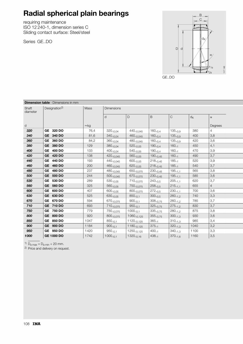
108
Radial spherical plain bearingsrequiring maintenanceISO 12 240-1, dimension series CSliding contact surface: Steel/steel
Series GE..DO
GE..DO
BC
D d
d
r
r
K
1s
2s
�
117
148
1) Da max = Da min + 20 mm.2) Price and delivery on request.
Dimension table · Dimensions in mm
Shaft diameter
Designation2) Mass Dimensions
d D B C dK �
d �kg Degrees
320 GE 320 DO 76,4 320–0,04 440–0,045 160–0,4 135–0,9 380 4
340 GE 340 DO 81,6 340–0,04 460–0,045 160–0,4 135–0,9 400 3,8
360 GE 360 DO 84,2 360–0,04 480–0,045 160–0,4 135–0,9 420 3,6
380 GE 380 DO 129 380–0,04 520–0,05 190–0,4 160–1 450 4,1
400 GE 400 DO 133 400–0,04 540–0,05 190–0,4 160–1 470 3,9
420 GE 420 DO 138 420–0,045 560–0,05 190–0,45 160–1 490 3,7
440 GE 440 DO 193 440–0,045 600–0,05 218–0,45 185–1 520 3,9
460 GE 460 DO 200 460–0,045 620–0,05 218–0,45 185–1 540 3,7
480 GE 480 DO 237 480–0,045 650–0,075 230–0,45 195–1,1 565 3,8
500 GE 500 DO 244 500–0,045 670–0,075 230–0,45 195–1,1 585 3,6
530 GE 530 DO 289 530–0,05 710–0,075 243–0,5 205–1,1 620 3,7
560 GE 560 DO 325 560–0,05 750–0,075 258–0,5 215–1,1 655 4
600 GE 600 DO 407 600–0,05 800–0,075 272–0,5 230–1,1 700 3,6
630 GE 630 DO 525 630–0,05 850–0,1 300–0,5 260–1,2 740 3,3
670 GE 670 DO 594 670–0,075 900–0,1 308–0,75 260–1,2 785 3,7
710 GE 710 DO 693 710–0,075 950–0,1 325–0,75 275–1,2 830 3,7
750 GE 750 DO 779 750–0,075 1000–0,1 335–0,75 280–1,2 875 3,8
800 GE 800 DO 920 800–0,075 1060–0,125 355–0,75 300–1,3 930 3,6
850 GE 850 DO 1047 850–0,1 1120–0,125 365–1 310–1,3 985 3,4
900 GE 900 DO 1184 900–0,1 1180–0,125 375–1 320–1,3 1040 3,2
950 GE 950 DO 1420 950–0,1 1250–0,125 400–1 340–1,3 1100 3,3
1000 GE 1000 DO 1742 1000–0,1 1320–0,16 438–1 370–1,6 1160 3,5

109
GE..DO – mounting dimensions
D da a
156
162
Chamfer dimensions Mounting dimensions Basic load ratings Radial internalclearance
Shaftdiameter
r1s r2s da Da1) dyn.
Cr
stat.C0r
CN
min. min. max. min. kN kN d
1,1 3 344,6 361 4 400 22 000 0,125 – 0,239 320
1,1 3 366,6 382 4 650 23 200 0,125 – 0,239 340
1,1 3 388,3 403 4 800 24 000 0,135 – 0,261 360
1,5 4 407,9 426 6 300 31 500 0,135 – 0,261 380
1,5 4 429,8 447 6 550 32 500 0,135 – 0,261 400
1,5 4 451,6 469 6 800 34 500 0,135 – 0,261 420
1,5 4 472 491 8 650 42 300 0,145 – 0,285 440
1,5 4 494 513 9 000 45 000 0,145 – 0,285 460
2 5 516 536 9 800 49 000 0,145 – 0,285 480
2 5 537,8 557 10 200 51 000 0,145 – 0,285 500
2 5 570,3 591 11 400 57 000 0,145 – 0,285 530
2 5 602 624 12 700 64 000 0,16 – 0,32 560
2 5 644,9 667 14 600 73 500 0,16 – 0,32 600
3 6 676,4 698 17 600 88 000 0,16 – 0,32 630
3 6 722 746 19 000 95 000 0,16 – 0,32 670
3 6 763,7 789 21 200 106 000 0,17 – 0,35 710
3 6 808,3 834 22 800 114 000 0,17 – 0,35 750
3 6 859,5 886 26 000 129 000 0,17 – 0,35 800
3 6 914,8 940 28 500 143 000 0,17 – 0,35 850
3 6 970 995 31 000 156 000 0,195 – 0,405 900
4 7,5 1024,6 1052 35 500 176 000 0,195 – 0,405 950
4 7,5 1074,1 1105 40 500 204 000 0,195 – 0,405 1000

110
Radial spherical plain bearingsrequiring maintenanceISO 12 240-1, dimension series GSliding contact surface: Steel/steel
Series GE..FOGE..FO-2RS
GE..FO
BC
D d
dK
�
r1s
r2s
117
046
1) No relubrication facility.2) Can only be relubricated via the outer ring.3) No lubrication groove on inner ring spherical surface.4) Also available in groups C2 and C3.5) Price and delivery on request.
Dimension table · Dimensions in mm
Shaft diameter
Designation Mass Dimensions
d D B C dK �
d without seals with seals �kg Degrees
6 GE 6 FO1)5) – 0,008 6–0,008 16–0,008 9–0,12 5–0,24 133) 21
8 GE 8 FO1)5) – 0,014 8–0,008 19–0,009 11–0,12 6–0,24 163) 21
10 GE 10 FO1)5) – 0,02 10–0,008 22–0,009 12–0,12 7–0,24 183) 18
12 GE 12 FO2)5) – 0,034 12–0,008 26–0,009 15–0,12 9–0,24 223) 18
15 – GE 15 FO-2RS5) 0,046 15–0,008 30–0,009 16–0,12 10–0,24 253) 16
17 – GE 17 FO-2RS5) 0,077 17–0,008 35–0,011 20–0,12 12–0,24 293) 19
20 – GE 20 FO-2RS 0,15 20–0,01 42–0,011 25–0,12 16–0,24 35,5 17
25 – GE 25 FO-2RS 0,19 25–0,01 47–0,011 28–0,12 18–0,24 40,7 17
30 – GE 30 FO-2RS 0,29 30–0,01 55–0,013 32–0,12 20–0,3 47 17
35 – GE 35 FO-2RS 0,38 35–0,012 62–0,013 35–0,12 22–0,3 53 16
40 – GE 40 FO-2RS 0,54 40–0,012 68–0,013 40–0,12 25–0,3 60 17
45 – GE 45 FO-2RS 0,68 45–0,012 75–0,013 43–0,12 28–0,3 66 15
50 – GE 50 FO-2RS 1,4 50–0,012 90–0,015 56–0,15 36–0,4 80 17
60 – GE 60 FO-2RS 2 60–0,015 105–0,015 63–0,15 40–0,4 92 17
70 – GE 70 FO-2RS 2,9 70–0,015 120–0,015 70–0,15 45–0,4 105 16
80 – GE 80 FO-2RS 3,5 80–0,015 130–0,018 75–0,2 50–0,5 115 14
90 – GE 90 FO-2RS 5,4 90–0,02 150–0,018 85–0,2 55–0,5 130 15
100 – GE 100 FO-2RS 5,9 100–0,02 160–0,025 85–0,2 55–0,5 140 14
110 – GE 110 FO-2RS 9,6 110–0,02 180–0,025 100–0,2 70–0,5 160 12
120 – GE 120 FO-2RS5) 15,1 120–0,02 210–0,03 115–0,25 70–0,6 180 16
140 – GE 140 FO-2RS5) 18,8 140–0,025 230–0,03 130–0,25 80–0,6 200 16
160 – GE 160 FO-2RS5) 24,7 160–0,025 260–0,035 135–0,25 80–0,7 225 16
180 – GE 180 FO-2RS5) 35,4 180–0,025 290–0,035 155–0,3 100–0,7 250 14
200 – GE 200 FO-2RS5) 44,8 200–0,03 320–0,04 165–0,3 100–0,8 275 15
220 – GE 220 FO-2RS5) 50,9 220–0,03 340–0,04 175–0,3 100–0,8 300 16
240 – GE 240 FO-2RS5) 64,9 240–0,03 370–0,04 190–0,35 110–0,8 325 15
260 – GE 260 FO-2RS5) 81,7 260–0,035 400–0,04 205–0,35 120–0,8 350 15
280 – GE 280 FO-2RS5) 96,5 280–0,035 430–0,045 210–0,35 120–0,9 375 15

111
GE..FO-2RS GE..FO-2RS – mounting dimensionsGE..FO – mounting dimensions
BC
D d
dK
�
r1s
r2s
117
047
D da a
156
141
Chamfer dimensions Mounting dimensions Basic load ratings Radial internal clearance4)
Shaft diameter
r1s r2s da Da dyn.Cr
stat.C0r
CN
min. min. max. min. N N d
0,3 0,3 9,3 12,5 5 500 27 500 0,032 – 0,068 6
0,3 0,3 11,6 15,5 8 150 40 500 0,032 – 0,068 8
0,3 0,3 13,4 17,5 10 800 54 000 0,032 – 0,068 10
0,3 0,3 16 21 17 000 85 000 0,04 – 0,082 12
0,3 0,3 19,2 24 21 200 106 000 0,04 – 0,082 15
0,3 0,3 21 27,5 30 000 146 000 0,04 – 0,082 17
0,3 0,6 25,2 33 48 000 240 000 0,05 – 0,1 20
0,6 0,6 29,5 38 62 000 310 000 0,05 – 0,1 25
0,6 1 34,4 44,5 80 000 400 000 0,05 – 0,1 30
0,6 1 39,7 51 100 000 500 000 0,06 – 0,12 35
0,6 1 44,7 57 127 000 640 000 0,06 – 0,12 40
0,6 1 50 63 156 000 780 000 0,06 – 0,12 45
0,6 1 57,1 75 245 000 1 220 000 0,06 – 0,12 50
1 1 67 87 315 000 1 560 000 0,072 – 0,142 60
1 1 78,2 99 400 000 2 000 000 0,072 – 0,142 70
1 1 87,1 108 490 000 2 450 000 0,072 – 0,142 80
1 1 98,3 123 610 000 3 050 000 0,085 – 0,165 90
1 1 111,2 134 655 000 3 250 000 0,085 – 0,165 100
1 1 124,8 150 950 000 4 750 000 0,085 – 0,165 110
1 1 138,4 173 1 080 000 5 400 000 0,085 – 0,165 120
1 1 151,9 191 1 370 000 6 800 000 0,1 – 0,192 140
1 1,1 180 219 1 530 000 7 650 000 0,1 – 0,192 160
1,1 1,1 196,1 239 2 120 000 10 600 000 0,1 – 0,192 180
1,1 1,1 220 267 2 320 000 11 600 000 0,11 – 0,214 200
1,1 1,1 243,6 295 2 550 000 12 700 000 0,11 – 0,214 220
1,1 1,1 263,6 319 3 050 000 15 300 000 0,125 – 0,239 240
1,1 1,1 283,6 342 3 550 000 18 000 000 0,125 – 0,239 260
1,1 1,1 310,6 370 3 800 000 19 000 000 0,125 – 0,239 280

112
Radial spherical plain bearingsrequiring maintenanceISO 12 240-1, dimension series WSliding contact surface: Steel/steel
Series GE..LO
GE..LO
BC
D d
dK
�
r1s
r2s
d2
117
049
1) Bore tolerance: H7 (arithmetic mean value).2) No relubrication facility.3) Not included in ISO 12 240-1, dimension series W.4) Cylindrical throughout.5) No lubrication groove on inner ring spherical surface.6) Price and delivery on request.7) Also available in groups C2 and C3.
Dimension table · Dimensions in mm
Shaft diameter
Designation Mass Dimensions
d D B C dK
d �kg
12 GE 12 LO2)4) 0,017 12+0,018 22–0,009 12–0,18 7–0,24 18
16 GE 16 LO4)5) 0,035 16+0,018 28–0,009 16–0,18 9–0,24 23
20 GE 20 LO5) 0,067 20+0,021 35–0,011 20–0,21 12–0,24 29
25 GE 25 LO 0,12 25+0,021 42–0,011 25–0,21 16–0,24 35,5
32 GE 32 LO 0,21 32+0,025 52–0,013 32–0,25 18–0,3 44
40 GE 40 LO 0,33 40+0,025 62–0,013 40–0,25 22–0,3 53
50 GE 50 LO 0,59 50+0,025 75–0,013 50–0,25 28–0,3 66
63 GE 63 LO 1,3 63+0,03 95–0,015 63–0,3 36–0,4 83
70 GE 70 LO3)6) 1,6 70+0,03 105–0,015 70–0,3 40–0,4 92
80 GE 80 LO 2,6 80+0,03 120–0,015 80–0,3 45–0,4 105
90 GE 90 LO3)6) 3 90+0,035 130–0,018 90–0,35 50–0,5 115
100 GE 100 LO 4,7 100+0,035 150–0,018 100–0,35 55–0,5 130
110 GE 110 LO3) 5,5 110+0,035 160–0,025 110–0,35 55–0,5 140
125 GE 125 LO 8,1 125+0,04 180–0,025 125–0,4 70–0,5 160
160 GE 160 LO6) 15,8 160+0,04 230–0,03 160–0,4 80–0,6 200
200 GE 200 LO6) 32,5 200+0,046 290–0,035 200–0,46 100–0,7 250
250 GE 250 LO6) 102 250+0,046 400–0,04 250–0,46 120–0,8 350
320 GE 320 LO6) 224 320+0,057 520–0,05 320–0,57 160–1 450
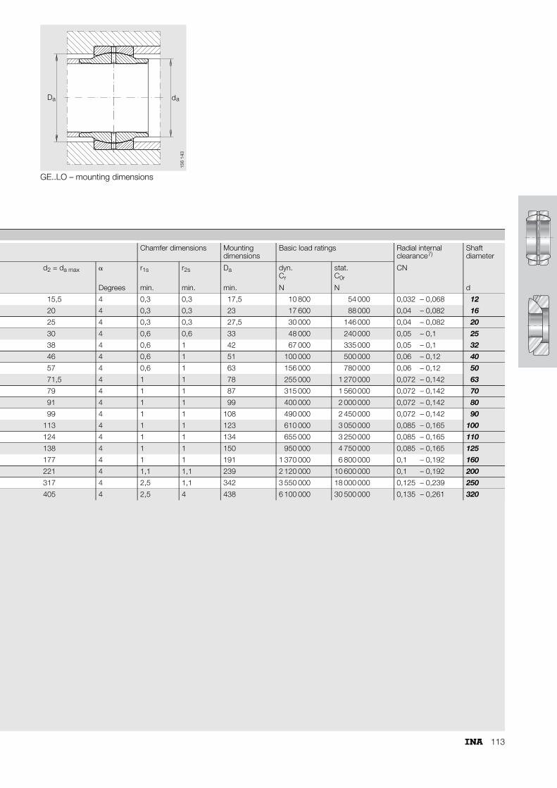
113
GE..LO – mounting dimensions
D da a
156
143
Chamfer dimensions Mounting dimensions
Basic load ratings Radial internal clearance7)
Shaft diameter
d2 = da max � r1s r2s Da dyn.Cr
stat.C0r
CN
Degrees min. min. min. N N d
15,5 4 0,3 0,3 17,5 10 800 54 000 0,032 – 0,068 12
20 4 0,3 0,3 23 17 600 88 000 0,04 – 0,082 16
25 4 0,3 0,3 27,5 30 000 146 000 0,04 – 0,082 20
30 4 0,6 0,6 33 48 000 240 000 0,05 – 0,1 25
38 4 0,6 1 42 67 000 335 000 0,05 – 0,1 32
46 4 0,6 1 51 100 000 500 000 0,06 – 0,12 40
57 4 0,6 1 63 156 000 780 000 0,06 – 0,12 50
71,5 4 1 1 78 255 000 1 270 000 0,072 – 0,142 63
79 4 1 1 87 315 000 1 560 000 0,072 – 0,142 70
91 4 1 1 99 400 000 2 000 000 0,072 – 0,142 80
99 4 1 1 108 490 000 2 450 000 0,072 – 0,142 90
113 4 1 1 123 610 000 3 050 000 0,085 – 0,165 100
124 4 1 1 134 655 000 3 250 000 0,085 – 0,165 110
138 4 1 1 150 950 000 4 750 000 0,085 – 0,165 125
177 4 1 1 191 1 370 000 6 800 000 0,1 – 0,192 160
221 4 1,1 1,1 239 2 120 000 10 600 000 0,1 – 0,192 200
317 4 2,5 1,1 342 3 550 000 18 000 000 0,125 – 0,239 250
405 4 2,5 4 438 6 100 000 30 500 000 0,135 – 0,261 320
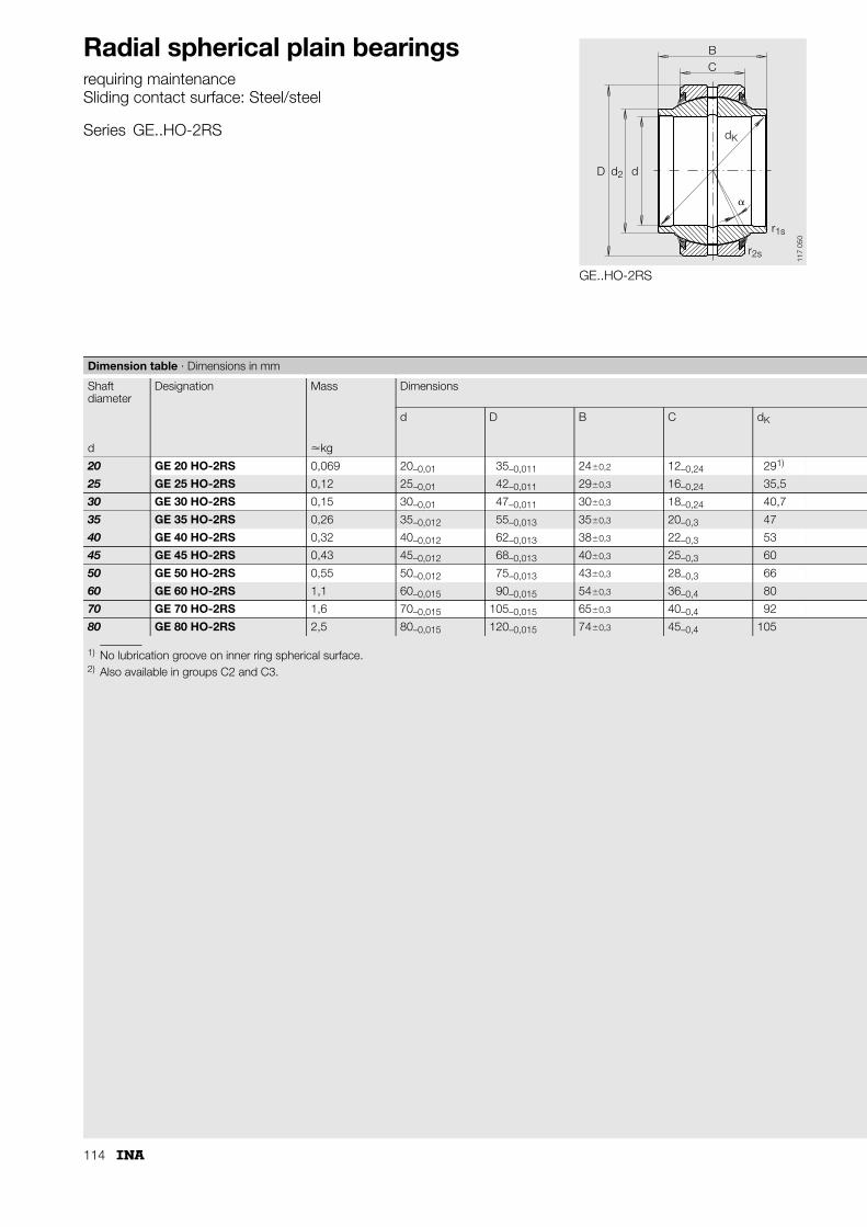
114
Radial spherical plain bearingsrequiring maintenanceSliding contact surface: Steel/steel
Series GE..HO-2RS
GE..HO-2RS
BC
D d
dK
�
r1s
r2s
d2
117
050
1) No lubrication groove on inner ring spherical surface.2) Also available in groups C2 and C3.
Dimension table · Dimensions in mm
Shaft diameter
Designation Mass Dimensions
d D B C dK
d �kg
20 GE 20 HO-2RS 0,069 20–0,01 35–0,011 24�0,2 12–0,24 291)
25 GE 25 HO-2RS 0,12 25–0,01 42–0,011 29�0,3 16–0,24 35,5
30 GE 30 HO-2RS 0,15 30–0,01 47–0,011 30�0,3 18–0,24 40,7
35 GE 35 HO-2RS 0,26 35–0,012 55–0,013 35�0,3 20–0,3 47
40 GE 40 HO-2RS 0,32 40–0,012 62–0,013 38�0,3 22–0,3 53
45 GE 45 HO-2RS 0,43 45–0,012 68–0,013 40�0,3 25–0,3 60
50 GE 50 HO-2RS 0,55 50–0,012 75–0,013 43�0,3 28–0,3 66
60 GE 60 HO-2RS 1,1 60–0,015 90–0,015 54�0,3 36–0,4 80
70 GE 70 HO-2RS 1,6 70–0,015 105–0,015 65�0,3 40–0,4 92
80 GE 80 HO-2RS 2,5 80–0,015 120–0,015 74�0,3 45–0,4 105
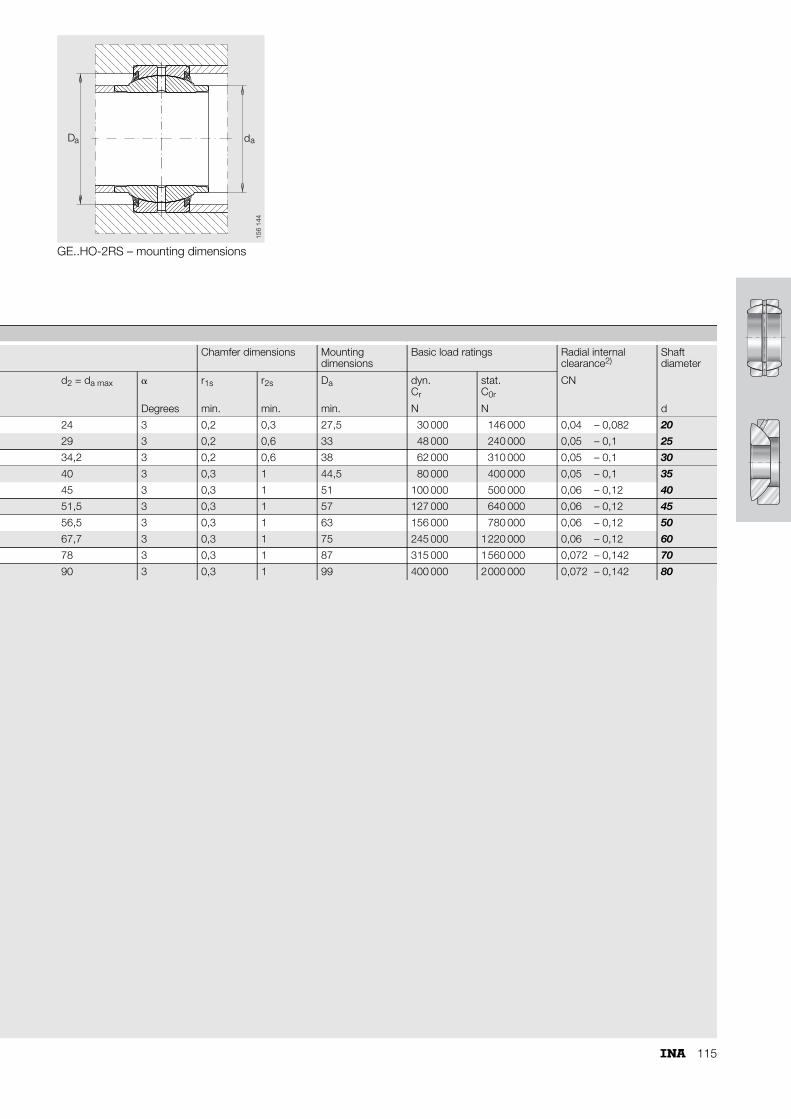
115
GE..HO-2RS – mounting dimensions
a aD d
156
144
Chamfer dimensions Mounting dimensions
Basic load ratings Radial internal clearance2)
Shaft diameter
d2 = da max � r1s r2s Da dyn.Cr
stat.C0r
CN
Degrees min. min. min. N N d
24 3 0,2 0,3 27,5 30 000 146 000 0,04 – 0,082 20
29 3 0,2 0,6 33 48 000 240 000 0,05 – 0,1 25
34,2 3 0,2 0,6 38 62 000 310 000 0,05 – 0,1 30
40 3 0,3 1 44,5 80 000 400 000 0,05 – 0,1 35
45 3 0,3 1 51 100 000 500 000 0,06 – 0,12 40
51,5 3 0,3 1 57 127 000 640 000 0,06 – 0,12 45
56,5 3 0,3 1 63 156 000 780 000 0,06 – 0,12 50
67,7 3 0,3 1 75 245 000 1220 000 0,06 – 0,12 60
78 3 0,3 1 87 315 000 1560 000 0,072 – 0,142 70
90 3 0,3 1 99 400 000 2000 000 0,072 – 0,142 80
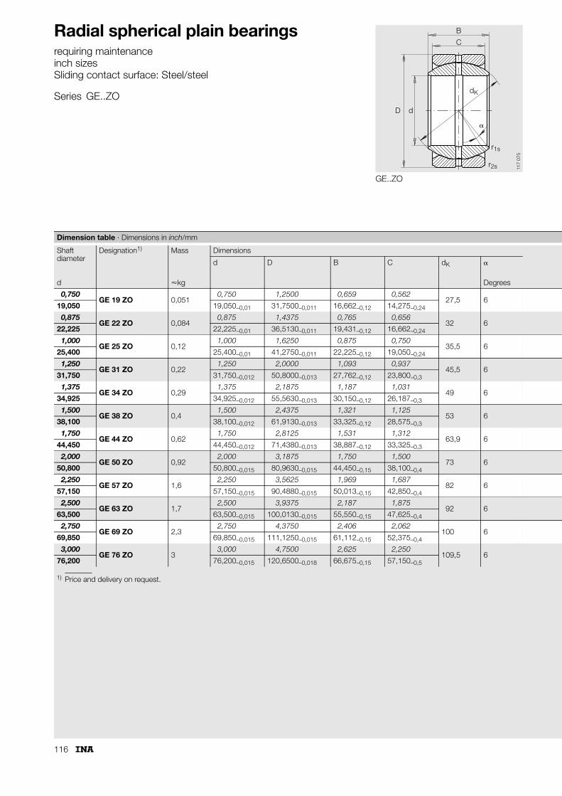
116
Radial spherical plain bearingsrequiring maintenanceinch sizesSliding contact surface: Steel/steel
Series GE..ZO
GE..ZO
B
C
D d
dK
r1s
r2s
�
117
075
1) Price and delivery on request.
Dimension table · Dimensions in inch/mm
Shaft diameter
Designation1) Mass Dimensions
d D B C dK �
d �kg Degrees
0,750GE 19 ZO 0,051
0,750 1,2500 0,659 0,56227,5 6
19,050 19,050–0,01 31,7500–0,011 16,662–0,12 14,275–0,24
0,875GE 22 ZO 0,084
0,875 1,4375 0,765 0,65632 6
22,225 22,225–0,01 36,5130–0,011 19,431–0,12 16,662–0,24
1,000GE 25 ZO 0,12
1,000 1,6250 0,875 0,75035,5 6
25,400 25,400–0,01 41,2750–0,011 22,225–0,12 19,050–0,24
1,250GE 31 ZO 0,22
1,250 2,0000 1,093 0,93745,5 6
31,750 31,750–0,012 50,8000–0,013 27,762–0,12 23,800–0,3
1,375GE 34 ZO 0,29
1,375 2,1875 1,187 1,03149 6
34,925 34,925–0,012 55,5630–0,013 30,150–0,12 26,187–0,3
1,500GE 38 ZO 0,4
1,500 2,4375 1,321 1,12553 6
38,100 38,100–0,012 61,9130–0,013 33,325–0,12 28,575–0,3
1,750GE 44 ZO 0,62
1,750 2,8125 1,531 1,31263,9 6
44,450 44,450–0,012 71,4380–0,013 38,887–0,12 33,325–0,3
2,000GE 50 ZO 0,92
2,000 3,1875 1,750 1,50073 6
50,800 50,800–0,015 80,9630–0,015 44,450–0,15 38,100–0,4
2,250GE 57 ZO 1,6
2,250 3,5625 1,969 1,68782 6
57,150 57,150–0,015 90,4880–0,015 50,013–0,15 42,850–0,4
2,500GE 63 ZO 1,7
2,500 3,9375 2,187 1,87592 6
63,500 63,500–0,015 100,0130–0,015 55,550–0,15 47,625–0,4
2,750GE 69 ZO 2,3
2,750 4,3750 2,406 2,062100 6
69,850 69,850–0,015 111,1250–0,015 61,112–0,15 52,375–0,4
3,000GE 76 ZO 3
3,000 4,7500 2,625 2,250109,5 6
76,200 76,200–0,015 120,6500–0,018 66,675–0,15 57,150–0,5

117
GE..ZO – mounting dimensions
a adD
156
158
Chamfer dimensions Mounting dimensions Basic load ratings Radial internalclearance
Shaftdiameterr1s r2s da Da dyn.
Cr
stat.C0r
min. min. max. min. N N d
0,3 0,6 21,8 24,5 31 400 94 200 0,08 – 0,180,750
19,050
0,3 0,6 25,4 28,5 42 600 127 000 0,08 – 0,180,875
22,225
0,3 0,6 27,6 31,5 54 100 162 000 0,08 – 0,181,000
25,400
0,6 0,6 36 40,5 86 600 259 000 0,08 – 0,181,250
31,750
0,6 1 38,6 43,5 102 000 307 000 0,08 – 0,181,375
34,925
0,6 1 41,2 46,5 121 000 363 000 0,08 – 0,181,500
38,100
0,6 1 50,7 57 170 000 511 000 0,08 – 0,181,750
44,450
0,6 1 57,9 65 222 000 667 000 0,08 – 0,182,000
50,800
0,6 1 64,9 73 281 000 843 000 0,1 – 0,22,250
57,150
1 1 73,3 82 350 000 1050 000 0,1 – 0,22,500
63,500
1 1 79,1 89 419 000 1250 000 0,1 – 0,22,750
69,850
1 1 86,8 98 500 000 1500 000 0,1 – 0,23,000
76,200

118
Radial spherical plain bearingsrequiring maintenanceISO 12 240-1, dimension series KSliding contact surface: Steel/bronze
Series GE..PB
GE..PB
BC
D d
dK
�
r1s
r2s
117
048
1) Bore tolerance: H7 (arithmetic mean value).2) No relubrication facility.3) Deviating from ISO 12 240-1, dimension series K.4) Price and delivery on request.
Dimension table · Dimensions in mm
Shaft diameter
Designation4) Mass Dimensions
d1) D B C dK �
d �kg Degrees
5 GE 5 PB2) 0,006 5+0,012 13–0,008 8–0,12 6 –0,24 11,112 13
6 GE 6 PB 0,01 6+0,012 16–0,008 9–0,12 6,75–0,24 12,7 13
8 GE 8 PB 0,018 8+0,015 19–0,009 12–0,12 9 –0,24 15,875 14
10 GE 10 PB 0,027 10+0,015 22–0,009 14–0,12 10,5 –0,24 19,05 13
12 GE 12 PB 0,043 12+0,018 26–0,009 16–0,12 12 –0,24 22,225 13
14 GE 14 PB 0,055 14+0,018 28–0,0093) 19–0,12 13,5 –0,24 25,4 16
16 GE 16 PB 0,08 16+0,018 32–0,011 21–0,12 15 –0,24 28,575 15
18 GE 18 PB 0,1 18+0,018 35–0,011 23–0,12 16,5 –0,24 31,75 15
20 GE 20 PB 0,15 20+0,021 40–0,011 25–0,12 18 –0,24 34,925 14
22 GE 22 PB 0,18 22+0,021 42–0,011 28–0,12 20 –0,24 38,1 15
25 GE 25 PB 0,24 25+0,021 47–0,011 31–0,12 22 –0,24 42,85 15
30 GE 30 PB 0,38 30+0,021 55–0,013 37–0,12 25 –0,3 50,8 17
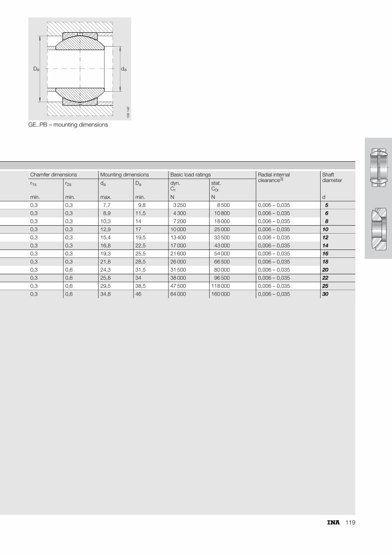
119
GE..PB – mounting dimensions
a aD d
156
142
Chamfer dimensions Mounting dimensions Basic load ratings Radial internalclearance3)
Shaftdiameterr1s r2s da Da dyn.
Cr
stat.C0r
min. min. max. min. N N d
0,3 0,3 7,7 9,8 3 250 8 500 0,006 – 0,035 5
0,3 0,3 8,9 11,5 4 300 10 800 0,006 – 0,035 6
0,3 0,3 10,3 14 7 200 18 000 0,006 – 0,035 8
0,3 0,3 12,9 17 10 000 25 000 0,006 – 0,035 10
0,3 0,3 15,4 19,5 13 400 33 500 0,006 – 0,035 12
0,3 0,3 16,8 22,5 17 000 43 000 0,006 – 0,035 14
0,3 0,3 19,3 25,5 21 600 54 000 0,006 – 0,035 16
0,3 0,3 21,8 28,5 26 000 66 500 0,006 – 0,035 18
0,3 0,6 24,3 31,5 31 500 80 000 0,006 – 0,035 20
0,3 0,6 25,8 34 38 000 96 500 0,006 – 0,035 22
0,3 0,6 29,5 38,5 47 500 118 000 0,006 – 0,035 25
0,3 0,6 34,8 46 64 000 160 000 0,006 – 0,035 30

120
Angular contact spherical plain bearingsrequiring maintenance,ISO 12 240-2Sliding contact surface: Steel/steel
Series GE..SX
GE..SX
BA
D
r
rCT
s
�
dD
dK
1
2s
r2s1s
r1s
117
051
1) Price and delivery on request.2) Basic load ratings in radial direction.
Dimension table · Dimensions in mm
Shaft diameter
Designation1) Mass Dimensions
d D T dK D1 B C
d �kg
25 GE 25 SX 0,14 25–0,012 47–0,014 15�0,25 42,5 31,4 14–0,2 14–0,2
28 GE 28 SX 0,18 28–0,012 52–0,016 16�0,25 47 35,7 15–0,2 15–0,2
30 GE 30 SX 0,21 30–0,012 55–0,016 17�0,25 50 36,1 16–0,2 16–0,2
35 GE 35 SX 0,27 35–0,012 62–0,016 18�0,25 56 42,4 17–0,24 17–0,24
40 GE 40 SX 0,33 40–0,012 68–0,016 19�0,25 60 46,8 18–0,24 18–0,24
45 GE 45 SX 0,42 45–0,012 75–0,016 20�0,25 66 52,9 19–0,24 19–0,24
50 GE 50 SX 0,46 50–0,012 80–0,016 20�0,25 74 59,1 19–0,24 19–0,24
55 GE 55 SX 0,68 55–0,015 90–0,018 23�0,25 80 62 22–0,3 22–0,3
60 GE 60 SX 0,73 60–0,015 95–0,018 23�0,25 86 68,1 22–0,3 22–0,3
65 GE 65 SX 0,77 65–0,015 100–0,018 23�0,25 92 75,6 22–0,3 22–0,3
70 GE 70 SX 1,1 70–0,015 110–0,018 25�0,25 102 82,2 24–0,3 24–0,3
80 GE 80 SX 1,5 80–0,015 125–0,02 29�0,25 115 90,5 27–0,3 27–0,3
90 GE 90 SX 2,1 90–0,02 140–0,02 32�0,25 130 103,3 30–0,4 30–0,4
100 GE 100 SX 2,3 100–0,02 150–0,02 32�0,25 140 114,3 30–0,4 30–0,4
110 GE 110 SX 3,9 110–0,02 170–0,025 38�0,25 160 125,8 36–0,4 36–0,4
120 GE 120 SX 4 120–0,02 180–0,025 38�0,25 170 135,4 36–0,4 36–0,4
130 GE 130 SX 6,1 130–0,025 200–0,03 45�0,35 190 148 42–0,5 42–0,5
140 GE 140 SX 6,5 140–0,025 210–0,03 45�0,35 200 160,6 42–0,5 42–0,5
150 GE 150 SX 7,9 150–0,025 225–0,03 48�0,35 213 170,9 45–0,5 45–0,5
160 GE 160 SX 9,4 160–0,025 240–0,03 51�0,35 225 181,4 48–0,5 48–0,5
170 GE 170 SX 13 170–0,025 260–0,035 57�0,35 250 194,3 54–0,5 54–0,5
180 GE 180 SX 17,5 180–0,025 280–0,035 64�0,35 260 205,5 61–0,5 61–0,5
190 GE 190 SX 18,3 190–0,03 290–0,035 64�0,35 275 211,8 61–0,6 61–0,6
200 GE 200 SX 23,3 200–0,03 310–0,035 70�0,35 290 229,2 66–0,6 66–0,6
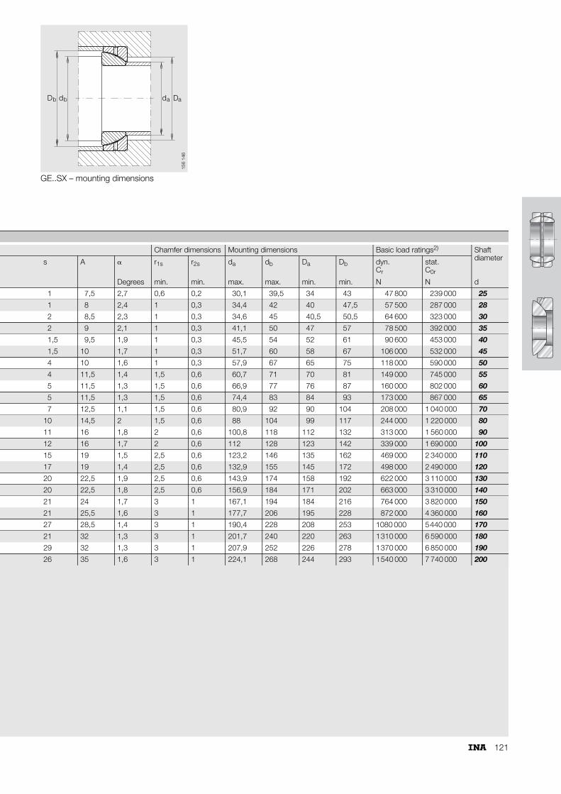
121
GE..SX – mounting dimensions
D db b Dda a
156
146
Chamfer dimensions Mounting dimensions Basic load ratings2) Shaft diameters A � r1s r2s da db Da Db dyn.
Cr
stat.C0r
Degrees min. min. max. max. min. min. N N d
1 7,5 2,7 0,6 0,2 30,1 39,5 34 43 47 800 239 000 25
1 8 2,4 1 0,3 34,4 42 40 47,5 57 500 287 000 28
2 8,5 2,3 1 0,3 34,6 45 40,5 50,5 64 600 323 000 30
2 9 2,1 1 0,3 41,1 50 47 57 78 500 392 000 35
1,5 9,5 1,9 1 0,3 45,5 54 52 61 90 600 453 000 40
1,5 10 1,7 1 0,3 51,7 60 58 67 106 000 532 000 45
4 10 1,6 1 0,3 57,9 67 65 75 118 000 590 000 50
4 11,5 1,4 1,5 0,6 60,7 71 70 81 149 000 745 000 55
5 11,5 1,3 1,5 0,6 66,9 77 76 87 160 000 802 000 60
5 11,5 1,3 1,5 0,6 74,4 83 84 93 173 000 867 000 65
7 12,5 1,1 1,5 0,6 80,9 92 90 104 208 000 1 040 000 70
10 14,5 2 1,5 0,6 88 104 99 117 244 000 1 220 000 80
11 16 1,8 2 0,6 100,8 118 112 132 313 000 1 560 000 90
12 16 1,7 2 0,6 112 128 123 142 339 000 1 690 000 100
15 19 1,5 2,5 0,6 123,2 146 135 162 469 000 2 340 000 110
17 19 1,4 2,5 0,6 132,9 155 145 172 498 000 2 490 000 120
20 22,5 1,9 2,5 0,6 143,9 174 158 192 622 000 3 110 000 130
20 22,5 1,8 2,5 0,6 156,9 184 171 202 663 000 3 310 000 140
21 24 1,7 3 1 167,1 194 184 216 764 000 3 820 000 150
21 25,5 1,6 3 1 177,7 206 195 228 872 000 4 360 000 160
27 28,5 1,4 3 1 190,4 228 208 253 1080 000 5440 000 170
21 32 1,3 3 1 201,7 240 220 263 1310 000 6 590 000 180
29 32 1,3 3 1 207,9 252 226 278 1370 000 6 850 000 190
26 35 1,6 3 1 224,1 268 244 293 1540 000 7 740 000 200
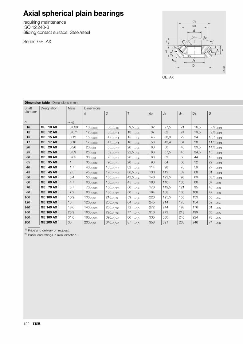
122
Axial spherical plain bearingsrequiring maintenanceISO 12 240-3Sliding contact surface: Steel/steel
Series GE..AX
GE..AX
d
d
dd
s
T C
rr
rr
A B
D
D1s
2s
2s1s
2
3
1
�K
117
052
1) Price and delivery on request.2) Basic load ratings in axial direction.
Dimension table · Dimensions in mm
Shaft diameter
Designation Mass Dimensions
d D T dK d2 d3 D1 B
d �kg
10 GE 10 AX 0,039 10–0,008 30–0,009 9,5 –0,4 32 27,5 21 16,5 7,9 –0,24
12 GE 12 AX 0,071 12–0,008 35–0,011 13 –0,4 37 32 24 19,5 9,3 –0,24
15 GE 15 AX 0,12 15–0,008 42–0,011 15 –0,4 45 38,9 29 24 10,7 –0,24
17 GE 17 AX 0,16 17–0,008 47–0,011 16 –0,4 50 43,4 34 28 11,5 –0,24
20 GE 20 AX 0,26 20–0,01 55–0,013 20 –0,4 60 50 40 33,5 14,3 –0,24
25 GE 25 AX 0,39 25–0,01 62–0,013 22,5 –0,4 66 57,5 45 34,5 16 –0,24
30 GE 30 AX 0,65 30–0,01 75–0,013 26 –0,4 80 69 56 44 18 –0,24
35 GE 35 AX 1 35–0,012 90–0,015 28 –0,4 98 84 66 52 22 –0,24
40 GE 40 AX 1,7 40–0,012 105–0,015 32 –0,4 114 98 78 59 27 –0,24
45 GE 45 AX 2,5 45–0,012 120–0,015 36,5 –0,4 130 112 89 68 31 –0,24
50 GE 50 AX1) 3,4 50–0,012 130–0,018 42,5 –0,4 140 122,5 98 69 33,5 –0,24
60 GE 60 AX1) 4,7 60–0,015 150–0,018 45 –0,4 160 140 108 86 37 –0,3
70 GE 70 AX1) 5,7 70–0,015 160–0,025 50 –0,4 170 149,5 121 95 40 –0,3
80 GE 80 AX1) 7,2 80–0,015 180–0,025 50 –0,4 194 168 130 108 42 –0,3
100 GE 100 AX1) 10,9 100–0,02 210–0,03 59 –0,4 220 195,5 155 133 50 –0,4
120 GE 120 AX1) 13 120–0,02 230–0,03 64 –0,4 245 214 170 154 52 –0,4
140 GE 140 AX1) 18,6 140–0,025 260–0,035 72 –0,5 272 244 198 176 61 –0,5
160 GE 160 AX1) 23,9 160–0,025 290–0,035 77 –0,5 310 272 213 199 65 –0,5
180 GE 180 AX1) 31,6 180–0,025 320–0,040 86 –0,5 335 300 240 224 70 –0,5
200 GE 200 AX1) 35 200–0,03 340–0,040 87 –0,5 358 321 265 246 74 –0,6
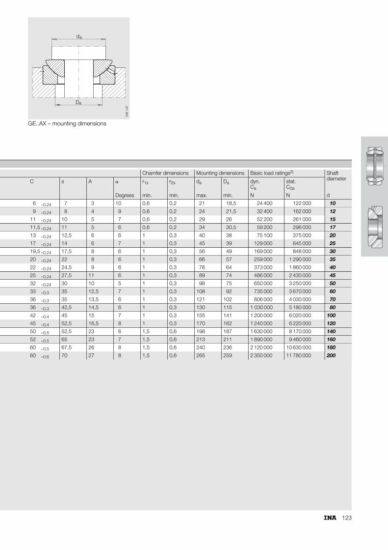
123
GE..AX – mounting dimensions
d
D
a
a
156
147
Chamfer dimensions Mounting dimensions Basic load ratings2) Shaft diameterC s A � r1s r2s da Da dyn.
Ca
stat.C0a
Degrees min. min. max. min. N N d
6 –0,24 7 3 10 0,6 0,2 21 18,5 24 400 122 000 10
9 –0,24 8 4 9 0,6 0,2 24 21,5 32 400 162 000 12
11 –0,24 10 5 7 0,6 0,2 29 26 52 200 261 000 15
11,5 –0,24 11 5 6 0,6 0,2 34 30,5 59 200 296 000 17
13 –0,24 12,5 6 6 1 0,3 40 38 75 100 375 000 20
17 –0,24 14 6 7 1 0,3 45 39 129 000 645 000 25
19,5 –0,24 17,5 8 6 1 0,3 56 49 169 000 848 000 30
20 –0,24 22 8 6 1 0,3 66 57 259 000 1 290 000 35
22 –0,24 24,5 9 6 1 0,3 78 64 373 000 1 860 000 40
25 –0,24 27,5 11 6 1 0,3 89 74 486 000 2 430 000 45
32 –0,24 30 10 5 1 0,3 98 75 650 000 3 250 000 50
33 –0,3 35 12,5 7 1 0,3 108 92 735 000 3 670 000 60
36 –0,3 35 13,5 6 1 0,3 121 102 806 000 4 030 000 70
36 –0,3 42,5 14,5 6 1 0,3 130 115 1 030 000 5 180 000 80
42 –0,4 45 15 7 1 0,3 155 141 1 200 000 6 020 000 100
45 –0,4 52,5 16,5 8 1 0,3 170 162 1 240 000 6 220 000 120
50 –0,5 52,5 23 6 1,5 0,6 198 187 1 630 000 8 170 000 140
52 –0,5 65 23 7 1,5 0,6 213 211 1 890 000 9 460 000 160
60 –0,5 67,5 26 8 1,5 0,6 240 236 2 120 000 10 630 000 180
60 –0,6 70 27 8 1,5 0,6 265 259 2 350 000 11 780 000 200

124
Maintenance-free rod endsCriteria for bearing selection
GIR..UK GIR..UK-2RS GAR..UK GAR..UK-2RS
Maintenance-free rod ends
Load
car
ryin
g ca
paci
ty C
C0r
r Bearing
Housing
Comparison of load carrying capacity for identical shaft diameter.
118
070

125
GIKFR..PW GAKFR..PW
Load
car
ryin
g ca
paci
ty
C
C0r
r Bearing
Housing
Maintenance-free rod ends
118
071

126
Maintenance-free rod ends Page
Design and safety guidelines ........................... 128
Accuracy .......................................................... 131
Special designs................................................. 131
Ordering example and ordering designation ... 131
p.p.SS
Features
Maintenance-free rod endsare complete units comprising a housing with an integral shank and a maintenance-free spherical plain bearing
– the integral shank has an external or internal thread– the spherical plain bearing is firmly seated and located
in the housing■ can support radial loads in a tensile or
compressive direction■ can transmit slow movements with small or
moderate swivel angles ■ are suitable for unilateral loads
– they are suitable for supporting alternating loads in certain cases
– they are suitable for alternating loads in combination with bearings GE..UK-2RS
■ are protected against corrosion by a zinc plating■ are maintenance-free
– in bearings with ELGOGLIDE®, lubricant leads to a considerable reduction in bearing life.
Sealed maintenance-free rod ends■ are protected against contaminants and water spray by
– lip seals.
Rod ends to ISO 12 240-4, dimension series E■ are fitted with radial spherical plain bearings GE..UK or
GE..UK-2RS■ have hard chromium/PTFE composite or
hard chromium/ELGOGLIDE® sliding contact surfaces■ have a right hand or left hand internal or external thread■ the thin walled design of the eye housing allows compact
adjacent constructions.
Rod ends to ISO 12 240-4, dimension series K■ incorporate a radial spherical plain bearing GE..PW■ have a steel/PTFE-bronze film sliding contact surface■ have a right hand or left hand internal or external thread.
Maintenance-free rod ends
˚C
■ to ISO 12 240-4, dimension series E, type F■ shank with internal thread■ suffix -2RS: lip seals on both sides, for operating
temperatures from –30 °C to +130 °C■ GIR..UK and GIL..UK
for shaft diameters from 6 mm to 30 mm■ GIR..UK-2RS and GIL..UK-2RS
for shaft diameters from 35 mm to 80 mm
■ to ISO 12 240-4, dimension series K, type F■ shank with internal thread■ GIPFR..PW has a fine pitch thread shank for standard
pneumatic cylinders to DIN 24 335■ GIKFR..PW and GIKFL..PW
for shaft diameters from 5 mm to 30 mm■ GIPFR..PW
for shaft diameters from 5 mm to 30 mm
GIR..UK(right hand thread)GIR..UK-2RS(right hand thread)GIL..UK(left hand thread)GIL..UK-2RS(left hand thread)
118
056
GIKFR..PW(right hand thread)GIPFR..PW(right hand thread)GIKFL..PW(left hand thread)
118
057
132
136

127
˚C
■ to ISO 12 240-4, dimension series E, type M■ shank with external thread■ suffix -2RS: lip seals on both sides,
for operating temperatures from –30 °C to +130 °C■ GAR..UK and GAL..UK
for shaft diameters from 6 mm to 30 mm■ GAR..UK-2RS and GAL..UK-2RS
for shaft diameters from 35 mm to 80 mm
■ ■
■ to ISO 12 240-4, dimension series K, type M■ shank with external thread■ for shaft diameters from 5 mm to 30 mm
GAR..UK(right hand thread)GAR..UK-2RS(right hand thread)GAL..UK(left hand thread)GAL..UK-2RS(left hand thread)
118
063
GAKFR..PW(right hand thread)GAKFL..PW(left hand thread)
118
059
134
138

128
Maintenance-free rod ends
Design and safety guidelinesBasic dynamic load ratingThe basic dynamic load rating Cr (dimension table) refers to the spherical plain bearing when fitted. It represents a factor used for calculating the bearing life.The equivalent bearing load and additional bending stresses in the shank area are taken into consideration if:■ in addition to radial load in a tensile or compressive direction,
other transverse forces act in an axial direction to the shank.
Basic static load ratingThe basic static load rating C0r (dimension table) of the rod end refers only to the load carrying capacity of the rod end housing. It indicates:■ the maximum constant tensile load when utilising 83%
of the material yield strength in the most highly stressed cross-section.
Permissible loading of rod endsThe permissible loading of rod ends depends on the type of load.Pulsating or alternating loads subject the material to greater stress than constant loads. The reduction factors fb must therefore be used for these operating conditions in calculation (Table 1).
In rod ends with the sliding material ELGOGLIDE®, the basic static load rating C0r of the housing is less than the basic dynamic load rating Cr of the bearing.
1) fb values are also valid for sealed designs (-2RS).
Table 1 · Load factors fbLoad type Series Load factor
fb
Allseries
1
GIR..UK1)
GAR..UK1)
GIKFR..PWGAKFR..PW
2,2532,253
Pperm = permissible rod end load N C0r = basic static radial load rating of rod end Nfb = load factor
Unilateral load
Time
+Fr 151
540
+Fr
Pulsating load
Time
151
541
+Fr
–Fr
Alternating load
Time
151
542
PpermC0r
fb--------=
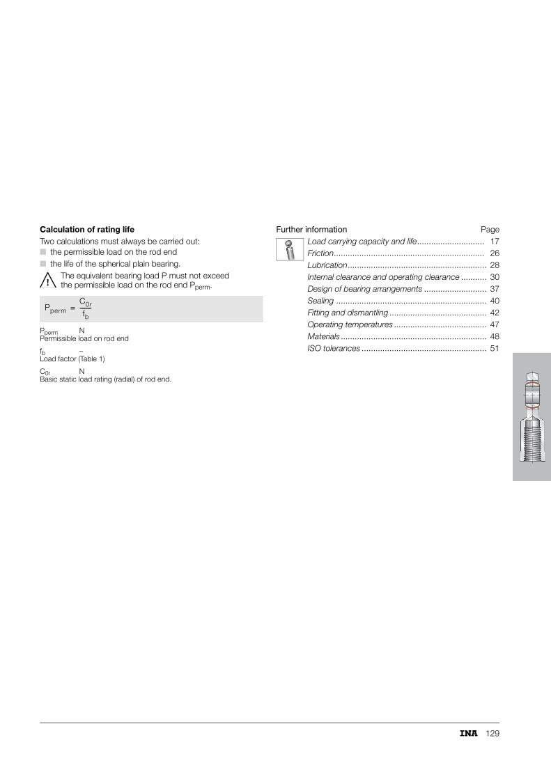
129
Calculation of rating lifeTwo calculations must always be carried out:■ the permissible load on the rod end■ the life of the spherical plain bearing.
The equivalent bearing load P must not exceed the permissible load on the rod end Pperm.
Pperm NPermissible load on rod end
fb –Load factor (Table 1)
C0r NBasic static load rating (radial) of rod end.
Further information PageLoad carrying capacity and life............................. 17Friction................................................................. 26Lubrication............................................................ 28Internal clearance and operating clearance ........... 30Design of bearing arrangements ........................... 37Sealing ................................................................. 40Fitting and dismantling .......................................... 42Operating temperatures ........................................ 47Materials ............................................................... 48ISO tolerances ...................................................... 51
PpermC0r
fb--------=

130
Maintenance-free rod ends
Calculation exampleGivenSwivel arm pivot of the feed device of a continuous furnace.
Operating parameters:
Bearing data:
RequiredRod end size with a bearing which allows a life of min. 13 000 h.
Calculation of rod end size
C0r min = 75 · 2,25 = 168,75 kN.
The rod end GIR 40 UK-2RS with a rod end basic load rating C0r = 194 kN is suitable for the application.
Calculation of rating life (see page 65)Radial spherical plain bearing GE 40 UK-2RS
v = 2,91 · 10–4 · 1 · 53 · 47 · 5,4 = 3,91 mm/s
f6 = 0,7579 · 1,009347 = 1,171
s (ELGOGLIDE®) for p = 59,86 N/mm2
from Figure 12, page 68 ⇒ 306 000 m, alternatively calculated using function from Table 2, page 68.
LW = 7 655 720 · 0,497 · 1,4 = 5 326 850 osc.
Load FR max = 75 kNLoad direction = unilateralLoad type = pulsating loadLoad factor fb = 2,25Bearing load FR min
FR max
==
22 kN75 kN
Swivel angle � = 47°Swivel frequency f = 5,4 min–1
Load frequency PHz = 0,09 HzOperating temperature t = 110 °C
Maintenance-free rod end = GIR..UK-2RSFactors for maintenance-free spherical plain bearings(Table 3, page 69)
Kf2f4f5
====
300 N/mm2
111,4
Cr = 277 kNdK = 53 mm
PpermC0r
fb--------=
C0r min FR max fb⋅=
P F2min + F2
max
2------------------------------------=
P 222 + 752
2-------------------------- 55,27 kN= =
p K PCr-----⋅=
p 300 55,27277
---------------⋅ 59,86 N/mm2= =
v 2,91 10–4 f4 dK � f⋅ ⋅ ⋅ ⋅ ⋅=
fv1,6228
1,000295v p⋅---------------------------------=
fv1,6228
1,0002953,91 59,86⋅------------------------------------------------- 1,515= =
f6 0,7579 1,0093�⋅=
s 791020
1,01599p------------------------ 791020
1,0159959,86--------------------------------- 306 045= = =
Lf2 fv⋅
f6------------ s f⋅
v-------- 14⋅ ⋅=
L 1 1,515⋅1,171
---------------------- 306 045 5,4⋅3,91
--------------------------------- 14⋅ ⋅ 7 655 720 osc.= =
fHz0,5442
1,0171PHz p⋅
--------------------------------=
fHz0,5442
1,01710,09 59,75⋅------------------------------------------ 0,497= =
LW L fHz f5⋅ ⋅=
LhWLW
f 60⋅------------=
LhW5 326 8505,4 60⋅
------------------------- 16 440 h= =

131
AccuracyThe main dimensions of these rod ends conform to ISO 12 240-4.All connecting threads have metric dimensions to DIN 13, central tolerance class, 6H, 6g.The stated thread length is the minimum usable length, based on normal chamfering practice for the thread of the mating component.
Special designsAvailable by agreement:■ rod ends with special threads■ rod ends with different anti-corrosion protection.
Ordering example and ordering designationMaintenance-free rod end to ISO 12 240-4, dimension series E, type Ffor:
Ordering designation: GIR 15 UK (Figure 1).
Figure 1 · Ordering example, ordering designation
shaft 15 mm.
p.p.SS
GIR 15 UK
d
118
082

132
Rod endsmaintenance-freeISO 12 240-4, dimension series E, type FSliding contact surface: hard chromium/PTFE
Series GIR..UKSliding material: PTFE composite
GIR..UK-2RSSliding material: ELGOGLIDE®
GIR..UK, GIR..UK-2RS
BC1
d1 d dK D
d2
r1s
� l3
d3
l7
h1l4
Wl5
d4
d5
118
041
1) For a left hand thread, the R is replaced by an L (example: GIL..).2) Thread runout or thread groove at manufacturer's discretion.3) Basic load rating of housing.
In rod ends with the sliding material ELGOGLIDE®, the basic static load rating C0r of the housing is less than the basic dynamic load rating Cr of the bearing.
Dimension table · Dimensions in mm
Shaft diameter
Designation1) Mass Dimensions
d D B dK d1 d2 d3 d4 h1
d without seals with seals �kg
6 GIR 6 UK – 0,021 6–0,008 14 6–0,12 10 8 21 M 6 10 30
8 GIR 8 UK – 0,039 8–0,008 16 8–0,12 13 10,2 24 M 8 12,5 36
10 GIR 10 UK – 0,061 10–0,008 19 9–0,12 16 13,2 29 M10 15 43
12 GIR 12 UK – 0,096 12–0,008 22 10–0,12 18 14,9 34 M12 17,5 50
15 GIR 15 UK – 0,18 15–0,008 26 12–0,12 22 18,4 40 M14 21 61
17 GIR 17 UK – 0,22 17–0,008 30 14–0,12 25 20,7 46 M16 24 67
20 GIR 20 UK – 0,35 20–0,01 35 16–0,12 29 24,1 53 M20�1,5 27,5 77
25 GIR 25 UK – 0,64 25–0,01 42 20–0,12 35,5 29,3 64 M24�2 33,5 94
30 GIR 30 UK – 0,93 30–0,01 47 22–0,12 40,7 34,2 73 M30�2 40 110
35 – GIR 35 UK-2RS 1,3 35–0,012 55 25–0,12 47 39,7 82 M36�3 47 125
40 – GIR 40 UK-2RS 2 40–0,012 62 28–0,12 53 45 92 M39�32) 52 142
45 – GIR 45 UK-2RS 2,5 45–0,012 68 32–0,12 60 50,7 102 M42�32) 58 145
50 – GIR 50 UK-2RS 3,5 50–0,012 75 35–0,12 66 55,9 112 M45�32) 62 160
60 – GIR 60 UK-2RS 5,5 60–0,015 90 44–0,15 80 66,8 135 M52�32) 70 175
70 – GIR 70 UK-2RS 8,6 70–0,015 105 49–0,15 92 77,8 160 M56�42) 80 200
80 – GIR 80 UK-2RS 12 80–0,015 120 55–0,15 105 89,4 180 M64�42) 95 230
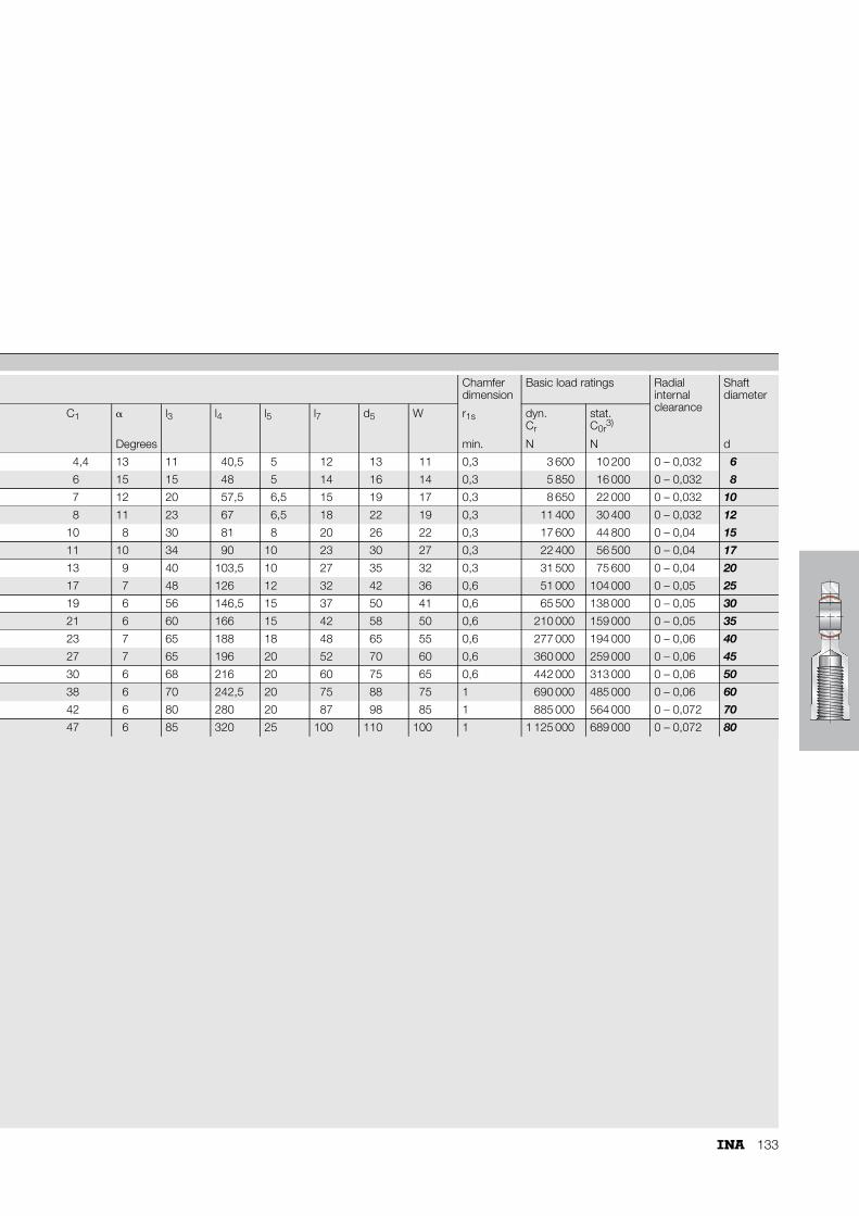
133
Chamfer dimension
Basic load ratings Radial internal clearance
Shaft diameter
C1 � l3 l4 l5 l7 d5 W r1s dyn.Cr
stat.C0r
3)
Degrees min. N N d
4,4 13 11 40,5 5 12 13 11 0,3 3 600 10 200 0 – 0,032 6
6 15 15 48 5 14 16 14 0,3 5 850 16 000 0 – 0,032 8
7 12 20 57,5 6,5 15 19 17 0,3 8 650 22 000 0 – 0,032 10
8 11 23 67 6,5 18 22 19 0,3 11 400 30 400 0 – 0,032 12
10 8 30 81 8 20 26 22 0,3 17 600 44 800 0 – 0,04 15
11 10 34 90 10 23 30 27 0,3 22 400 56 500 0 – 0,04 17
13 9 40 103,5 10 27 35 32 0,3 31 500 75 600 0 – 0,04 20
17 7 48 126 12 32 42 36 0,6 51 000 104 000 0 – 0,05 25
19 6 56 146,5 15 37 50 41 0,6 65 500 138 000 0 – 0,05 30
21 6 60 166 15 42 58 50 0,6 210 000 159 000 0 – 0,05 35
23 7 65 188 18 48 65 55 0,6 277 000 194 000 0 – 0,06 40
27 7 65 196 20 52 70 60 0,6 360 000 259 000 0 – 0,06 45
30 6 68 216 20 60 75 65 0,6 442 000 313 000 0 – 0,06 50
38 6 70 242,5 20 75 88 75 1 690 000 485 000 0 – 0,06 60
42 6 80 280 20 87 98 85 1 885 000 564 000 0 – 0,072 70
47 6 85 320 25 100 110 100 1 1 125 000 689 000 0 – 0,072 80

134
Rod endsmaintenance-freeISO 12 240-4, dimension series E, type MSliding contact surface: hard chromium/PTFE
Series GAR..UKSliding material: PTFE composite
GAR..UK-2RSSliding material: ELGOGLIDE®
GAR..UK, GAR..UK-2RS
BC1
d1 d K D
d2
r1s
�
l1
d3
l7
hl2
d
118
031
1) For a left hand thread, the R is replaced by an L (example: GAL..).2) Basic load rating of housing.
In rod ends with the sliding material ELGOGLIDE®, the basic static load rating C0r of the housing is less than the basic dynamic load rating Cr of the bearing.
Dimension table · Dimensions in mm
Shaft diameter
Designation1) Mass Dimensions
d D B dK d1 d2 d3
d without seals with seals �kg
6 GAR 6 UK – 0,017 6–0,008 14 6–0,12 10 8 21 M 6
8 GAR 8 UK – 0,029 8–0,008 16 8–0,12 13 10,2 24 M 8
10 GAR 10 UK – 0,051 10–0,008 19 9–0,12 16 13,2 29 M10
12 GAR 12 UK – 0,086 12–0,008 22 10–0,12 18 14,9 34 M12
15 GAR 15 UK – 0,14 15–0,008 26 12–0,12 22 18,4 40 M14
17 GAR 17 UK – 0,19 17–0,008 30 14–0,12 25 20,7 46 M16
20 GAR 20 UK – 0,31 20–0,01 35 16–0,12 29 24,1 53 M20�1,5
25 GAR 25 UK – 0,56 25–0,01 42 20–0,12 35,5 29,3 64 M24�2
30 GAR 30 UK – 0,89 30–0,01 47 22–0,12 40,7 34,2 73 M30�2
35 – GAR 35 UK-2RS 1,4 35–0,012 55 25–0,12 47 39,7 82 M36�3
40 – GAR 40 UK-2RS 1,8 40–0,012 62 28–0,12 53 45 92 M39�3
45 – GAR 45 UK-2RS 2,6 45–0,012 68 32–0,12 60 50,7 102 M42�3
50 – GAR 50 UK-2RS 3,4 50–0,012 75 35–0,12 66 55,9 112 M45�3
60 – GAR 60 UK-2RS 5,9 60–0,015 90 44–0,15 80 66,8 135 M52�3
70 – GAR 70 UK-2RS 8,2 70–0,015 105 49–0,15 92 77,8 160 M56�4
80 – GAR 80 UK-2RS 12 80–0,015 120 55–0,15 105 89,4 180 M64�4
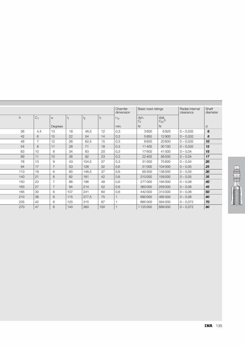
135
Chamfer dimension
Basic load ratings Radial internal clearance
Shaft diameter
h C1 � l1 l2 l7 r1s dyn.Cr
stat.C0r
2)
Degrees min. N N d
36 4,4 13 18 46,5 12 0,3 3 600 6 920 0 – 0,032 6
42 6 15 22 54 14 0,3 5 850 12 900 0 – 0,032 8
48 7 12 26 62,5 15 0,3 8 650 20 600 0 – 0,032 10
54 8 11 28 71 18 0,3 11 400 30 100 0 – 0,032 12
63 10 8 34 83 20 0,3 17 600 41 500 0 – 0,04 15
69 11 10 36 92 23 0,3 22 400 56 500 0 – 0,04 17
78 13 9 43 104,5 27 0,3 31 500 75 600 0 – 0,04 20
94 17 7 53 126 32 0,6 51 000 104 000 0 – 0,05 25
110 19 6 65 146,5 37 0,6 65 500 138 000 0 – 0,05 30
140 21 6 82 181 42 0,6 210 000 159 000 0 – 0,05 35
150 23 7 86 196 48 0,6 277 000 194 000 0 – 0,06 40
163 27 7 94 214 52 0,6 360 000 259 000 0 – 0,06 45
185 30 6 107 241 60 0,6 442 000 313 000 0 – 0,06 50
210 38 6 115 277,5 75 1 690 000 485 000 0 – 0,06 60
235 42 6 125 315 87 1 885 000 564 000 0 – 0,072 70
270 47 6 140 360 100 1 1 125 000 689 000 0 – 0,072 80
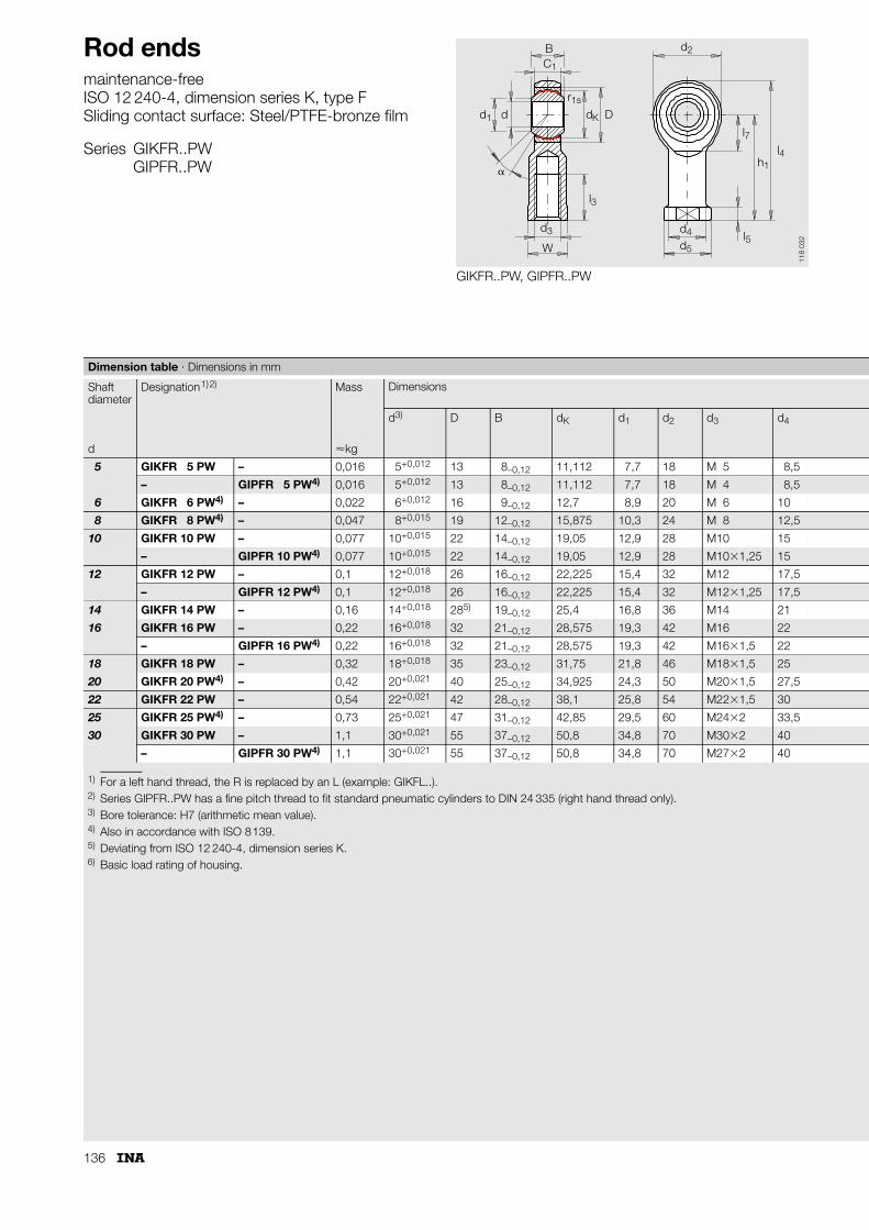
136
Rod endsmaintenance-freeISO 12 240-4, dimension series K, type FSliding contact surface: Steel/PTFE-bronze film
Series GIKFR..PWGIPFR..PW
GIKFR..PW, GIPFR..PW
BC1
d1 d dK D
d2
r1s
�
l3
d3
l7
h1
l4
Wl5
d4
d5
118
032
1) For a left hand thread, the R is replaced by an L (example: GIKFL..).2) Series GIPFR..PW has a fine pitch thread to fit standard pneumatic cylinders to DIN 24 335 (right hand thread only).3) Bore tolerance: H7 (arithmetic mean value).4) Also in accordance with ISO 8139.5) Deviating from ISO 12 240-4, dimension series K.6) Basic load rating of housing.
Dimension table · Dimensions in mm
Shaft diameter
Designation1)2) Mass Dimensions
d3) D B dK d1 d2 d3 d4
d �kg
5 GIKFR 5 PW – 0,016 5+0,012 13 8–0,12 11,112 7,7 18 M 5 8,5
– GIPFR 5 PW4) 0,016 5+0,012 13 8–0,12 11,112 7,7 18 M 4 8,5
6 GIKFR 6 PW4) – 0,022 6+0,012 16 9–0,12 12,7 8,9 20 M 6 10
8 GIKFR 8 PW4) – 0,047 8+0,015 19 12–0,12 15,875 10,3 24 M 8 12,5
10 GIKFR 10 PW – 0,077 10+0,015 22 14–0,12 19,05 12,9 28 M10 15
– GIPFR 10 PW4) 0,077 10+0,015 22 14–0,12 19,05 12,9 28 M10�1,25 15
12 GIKFR 12 PW – 0,1 12+0,018 26 16–0,12 22,225 15,4 32 M12 17,5
– GIPFR 12 PW4) 0,1 12+0,018 26 16–0,12 22,225 15,4 32 M12�1,25 17,5
14 GIKFR 14 PW – 0,16 14+0,018 285) 19–0,12 25,4 16,8 36 M14 21
16 GIKFR 16 PW – 0,22 16+0,018 32 21–0,12 28,575 19,3 42 M16 22
– GIPFR 16 PW4) 0,22 16+0,018 32 21–0,12 28,575 19,3 42 M16�1,5 22
18 GIKFR 18 PW – 0,32 18+0,018 35 23–0,12 31,75 21,8 46 M18�1,5 25
20 GIKFR 20 PW4) – 0,42 20+0,021 40 25–0,12 34,925 24,3 50 M20�1,5 27,5
22 GIKFR 22 PW – 0,54 22+0,021 42 28–0,12 38,1 25,8 54 M22�1,5 30
25 GIKFR 25 PW4) – 0,73 25+0,021 47 31–0,12 42,85 29,5 60 M24�2 33,5
30 GIKFR 30 PW – 1,1 30+0,021 55 37–0,12 50,8 34,8 70 M30�2 40
– GIPFR 30 PW4) 1,1 30+0,021 55 37–0,12 50,8 34,8 70 M27�2 40

137
Chamfer dimension
Basic load ratings Radial internal clearance
Shaft diameter
h1 C1 � l3 l4 l5 l7 d5 W r1s dyn.Cr
stat.C0r
6)
Degrees min. N N d
27 6 13 10 36 4 10 11 9 0,3 6 000 9 180 0 – 0,035 5
27 6 13 10 36 4 10 11 9 0,3 6 000 9 180 0 – 0,035
30 6,75 13 12 40 5 11 13 11 0,3 7 650 8 000 0 – 0,035 6
36 9 14 16 48 5 13 16 14 0,3 12 900 13 100 0 – 0,035 8
43 10,5 13 20 57 6,5 15 19 17 0,3 18 000 18 500 0 – 0,035 10
43 10,5 13 20 57 6,5 15 19 17 0,3 18 000 18 500 0 – 0,035
50 12 13 22 66 6,5 17 22 19 0,3 24 000 20 800 0 – 0,035 12
50 12 13 22 66 6,5 17 22 19 0,3 24 000 20 800 0 – 0,035
57 13,5 16 25 75 8 18 26 22 0,3 31 000 32 000 0 – 0,035 14
64 15 15 28 85 8 23 28 22 0,3 39 000 45 200 0 – 0,035 16
64 15 15 28 85 8 23 28 22 0,3 39 000 45 200 0 – 0,035
71 16,5 15 32 94 10 25 31 27 0,3 47 500 46 900 0 – 0,035 18
77 18 14 33 102 10 26 35 30 0,3 57 000 45 600 0 – 0,035 20
84 20 15 37 111 12 29 38 32 0,3 68 000 61 100 0 – 0,035 22
94 22 15 42 124 12 32 42 36 0,3 85 000 72 800 0 – 0,035 25
110 25 17 51 145 15 37 50 41 0,3 114 000 95 900 0 – 0,035 30
110 25 17 51 145 15 37 50 41 0,3 114 000 95 900 0 – 0,035

138
Rod endsmaintenance-freeISO 12 240-4, dimension series K, type MSliding contact surface: Steel/PTFE-bronze film
Series GAKFR..PW
GAKFR..PW
BC1
d1 d K D
d2
r1s
�
l1
d3
l7
hl2
d
118
033
1) For a left hand thread, the R is replaced by an L (example: GAKFL..).2) Bore tolerance: H7 (arithmetic mean value).3) Deviating from ISO 12 240-4, dimension series K.4) Basic load rating of housing.
Dimension table · Dimensions in mm
Shaft diameter
Designation1) Mass Dimensions
d2) D B dK d1 d2 d3 h
d �kg
5 GAKFR 5 PW 0,013 5+0,012 13 8–0,12 11,112 7,7 18 M 5 33
6 GAKFR 6 PW 0,02 6+0,012 16 9–0,12 12,7 8,9 20 M 6 36
8 GAKFR 8 PW 0,038 8+0,015 19 12–0,12 15,875 10,3 24 M 8 42
10 GAKFR 10 PW 0,055 10+0,015 22 14–0,12 19,05 12,9 28 M10 48
12 GAKFR 12 PW 0,085 12+0,018 26 16–0,12 22,225 15,4 32 M12 54
14 GAKFR 14 PW 0,14 14+0,018 283) 19–0,12 25,4 16,8 36 M14 60
16 GAKFR 16 PW 0,21 16+0,018 32 21–0,12 28,575 19,3 42 M16 66
18 GAKFR 18 PW 0,28 18+0,018 35 23–0,12 31,75 21,8 46 M18�1,5 72
20 GAKFR 20 PW 0,38 20+0,021 40 25–0,12 34,925 24,3 50 M20�1,5 78
22 GAKFR 22 PW 0,48 22+0,021 42 28–0,12 38,1 25,8 54 M22�1,5 84
25 GAKFR 25 PW 0,64 25+0,021 47 31–0,12 42,85 29,5 60 M24�2 94
30 GAKFR 30 PW 1,1 30+0,021 55 37–0,12 50,8 34,8 70 M30�2 110

139
Chamfer dimension
Basic load ratings Radial internal clearance
Shaft diameter
C1 � l1 l2 l7 r1s dyn.Cr
stat.C4)
Degrees min. N N d
6 13 19 42 – 0,3 6 000 4 890 0 – 0,035 5
6,75 13 21 46 – 0,3 7 650 6 920 0 – 0,035 6
9 14 25 54 – 0,3 12 900 12 900 0 – 0,035 8
10,5 13 28 62 – 0,3 18 000 18 500 0 – 0,035 10
12 13 32 70 – 0,3 24 000 20 800 0 – 0,035 12
13,5 16 36 78 18 0,3 31 000 32 000 0 – 0,035 14
15 15 37 87 23 0,3 39 000 45 200 0 – 0,035 16
16,5 15 41 95 25 0,3 47 500 46 900 0 – 0,035 18
18 14 45 103 26 0,3 57 000 45 600 0 – 0,035 20
20 15 48 111 29 0,3 68 000 61 100 0 – 0,035 22
22 15 55 124 32 0,3 85 000 72 800 0 – 0,035 25
25 17 66 145 37 0,3 114 000 95 900 0 – 0,035 30

140
Rod ends requiring maintenanceHydraulic rod endsCriteria for bearing selection
GAKFR..PBGIKFR..PBGAR..DOGAR..DO-2RS
GIR..DOGIR..DO-2RS
C
C0r
r
Rod ends requiring maintenance
Load
car
ryin
g ca
paci
ty
Housing
Bearing
Comparison of load carrying capacity for identical shaft diameter.
118
072

141
GF..DOGIHR-K..DOGIHN-K..LO GK..DO
C
C0r
r
Load
car
ryin
g ca
paci
ty
Hydraulic rod ends
Bearing
Housing
118
073
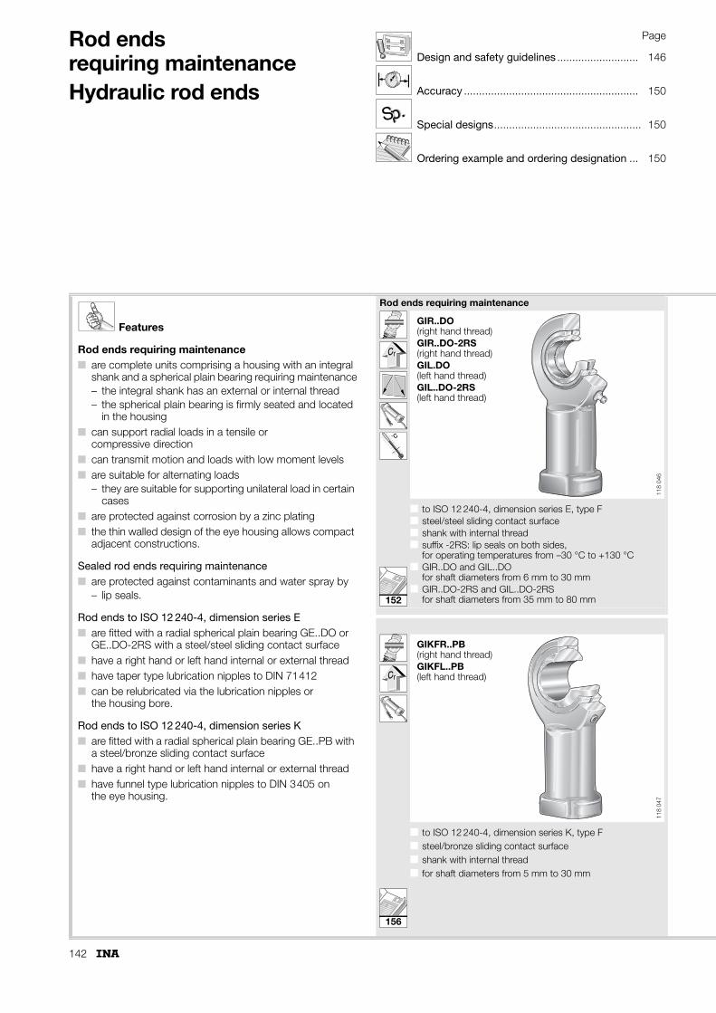
142
Rod ends requiring maintenanceHydraulic rod ends
Page
Design and safety guidelines ........................... 146
Accuracy .......................................................... 150
Special designs................................................. 150
Ordering example and ordering designation ... 150
p.p.SS
Features
Rod ends requiring maintenance■ are complete units comprising a housing with an integral
shank and a spherical plain bearing requiring maintenance– the integral shank has an external or internal thread– the spherical plain bearing is firmly seated and located
in the housing■ can support radial loads in a tensile or
compressive direction■ can transmit motion and loads with low moment levels■ are suitable for alternating loads
– they are suitable for supporting unilateral load in certain cases
■ are protected against corrosion by a zinc plating■ the thin walled design of the eye housing allows compact
adjacent constructions.
Sealed rod ends requiring maintenance■ are protected against contaminants and water spray by
– lip seals.
Rod ends to ISO 12 240-4, dimension series E■ are fitted with a radial spherical plain bearing GE..DO or
GE..DO-2RS with a steel/steel sliding contact surface■ have a right hand or left hand internal or external thread■ have taper type lubrication nipples to DIN 71412■ can be relubricated via the lubrication nipples or
the housing bore.
Rod ends to ISO 12 240-4, dimension series K■ are fitted with a radial spherical plain bearing GE..PB with
a steel/bronze sliding contact surface■ have a right hand or left hand internal or external thread■ have funnel type lubrication nipples to DIN 3405 on
the eye housing.
Rod ends requiring maintenance
˚C
■ to ISO 12 240-4, dimension series E, type F■ steel/steel sliding contact surface■ shank with internal thread■ suffix -2RS: lip seals on both sides,
for operating temperatures from –30 °C to +130 °C■ GIR..DO and GIL..DO
for shaft diameters from 6 mm to 30 mm■ GIR..DO-2RS and GIL..DO-2RS
for shaft diameters from 35 mm to 80 mm
■ to ISO 12 240-4, dimension series K, type F■ steel/bronze sliding contact surface■ shank with internal thread■ for shaft diameters from 5 mm to 30 mm
GIR..DO(right hand thread)GIR..DO-2RS(right hand thread)GIL.DO(left hand thread)GIL..DO-2RS(left hand thread)
118
046
GIKFR..PB(right hand thread)GIKFL..PB(left hand thread)
118
047
152
156
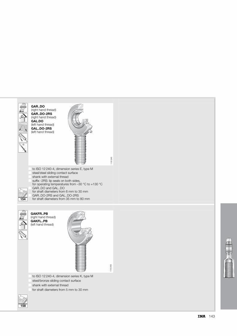
143
˚C
■ to ISO 12 240-4, dimension series E, type M■ steel/steel sliding contact surface■ shank with external thread■ suffix -2RS: lip seals on both sides,
for operating temperatures from –30 °C to +130 °C■ GAR..DO and GAL..DO
for shaft diameters from 6 mm to 30 mm■ GAR..DO-2RS and GAL..DO-2RS
for shaft diameters from 35 mm to 80 mm
■ ■
■ to ISO 12 240-4, dimension series K, type M■ steel/bronze sliding contact surface■ shank with external thread■ for shaft diameters from 5 mm to 30 mm
GAR..DO(right hand thread)GAR..DO-2RS(right hand thread)GAL.DO(left hand thread)GAL..DO-2RS(left hand thread)
118
048
GAKFR..PB(right hand thread)GAKFL..PB(left hand thread)
118
049
154
158
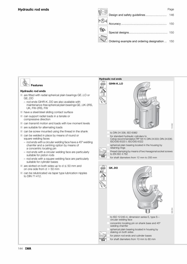
144
Hydraulic rod ends Page
Design and safety guidelines ........................... 146
Accuracy .......................................................... 150
Special designs................................................. 150
Ordering example and ordering designation ... 150
p.p.SS
Features
Hydraulic rod ends■ are fitted with radial spherical plain bearings GE..LO or
GE..DO– rod ends GIHR-K..DO are also available with
maintenance-free spherical plain bearings GE..UK-2RS, UK, FW-2RS, FW
■ have a steel/steel sliding contact surface■ can support radial loads in a tensile or
compressive direction■ can transmit motion and loads with low moment levels■ are suitable for alternating loads■ can be screw mounted using the thread in the shank■ can be welded in place by means of round or
square welding faces– rod ends with a circular welding face have a 45º welding
chamfer and a centring option by means of a concentric locating pin
– rod ends with a circular welding face are particularly suitable for piston rods
– rod ends with a square welding face are particularly suitable for cylinder bases
■ are slotted on both sides up to d � 50 mm and on one side from d � 50 mm
■ can be relubricated via taper type lubrication nipples to DIN 71 412.
Hydraulic rod ends
■ to DIN 24 338, ISO 6982■ for standard hydraulic cylinders to
Cetop recommendation RP 58 H; DIN 24333; DIN 24336; ISO/DIS 6020 I; ISO/DIS 6022
■ spherical plain bearing located in the housing by retaining rings
■ thread clamping by means of two hexagonal socket screws to EN ISO 4 762
■ for shaft diameters from 12 mm to 200 mm
■ to ISO 12 240-4, dimension series E, type S – circular welding face
■ concentric locating pin on shank base and 45º welding chamfer
■ spherical plain bearing located in housing by staking on both sides
■ for piston rod ends and cylinder bases■ for shaft diameters from 10 mm to 80 mm
GIHN-K..LO
118
050
GK..DO00
8 05
4
160
164
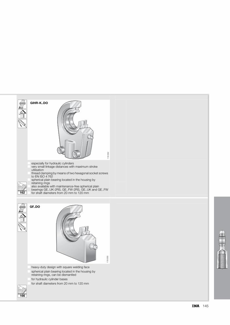
145
■ especially for hydraulic cylinders■ very small linkage distances with maximum stroke
utilisation■ thread clamping by means of two hexagonal socket screws
to EN ISO 4 762 ■ spherical plain bearing located in the housing by
retaining rings■ also available with maintenance-free spherical plain
bearings GE..UK-2RS, GE..FW-2RS, GE..UK and GE..FW■ for shaft diameters from 20 mm to 120 mm
■ ■
■ heavy-duty design with square welding face■ spherical plain bearing located in the housing by
retaining rings, can be dismantled■ for hydraulic cylinder bases■ for shaft diameters from 20 mm to 120 mm
GIHR-K..DO11
8 05
2
GF..DO
118
055
162
166
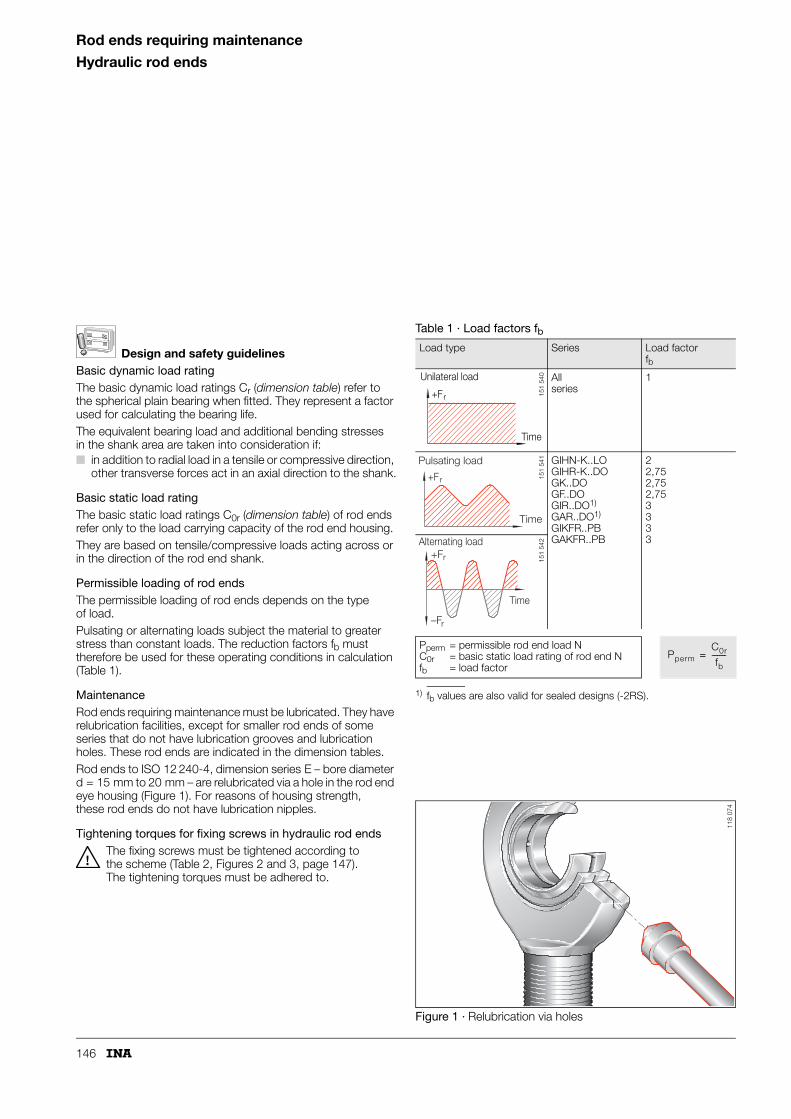
146
Rod ends requiring maintenance
Hydraulic rod ends
Design and safety guidelinesBasic dynamic load ratingThe basic dynamic load ratings Cr (dimension table) refer to the spherical plain bearing when fitted. They represent a factor used for calculating the bearing life.The equivalent bearing load and additional bending stresses in the shank area are taken into consideration if:■ in addition to radial load in a tensile or compressive direction,
other transverse forces act in an axial direction to the shank.
Basic static load ratingThe basic static load ratings C0r (dimension table) of rod ends refer only to the load carrying capacity of the rod end housing. They are based on tensile/compressive loads acting across or in the direction of the rod end shank.
Permissible loading of rod endsThe permissible loading of rod ends depends on the type of load.Pulsating or alternating loads subject the material to greater stress than constant loads. The reduction factors fb must therefore be used for these operating conditions in calculation (Table 1).
MaintenanceRod ends requiring maintenance must be lubricated. They have relubrication facilities, except for smaller rod ends of some series that do not have lubrication grooves and lubrication holes. These rod ends are indicated in the dimension tables.Rod ends to ISO 12 240-4, dimension series E – bore diameter d = 15 mm to 20 mm – are relubricated via a hole in the rod end eye housing (Figure 1). For reasons of housing strength, these rod ends do not have lubrication nipples.
Tightening torques for fixing screws in hydraulic rod endsThe fixing screws must be tightened according to the scheme (Table 2, Figures 2 and 3, page 147). The tightening torques must be adhered to.
1) fb values are also valid for sealed designs (-2RS).
Figure 1 · Relubrication via holes
Table 1 · Load factors fbLoad type Series Load factor
fb
Allseries
1
GIHN-K..LOGIHR-K..DOGK..DOGF..DOGIR..DO1)
GAR..DO1)
GIKFR..PBGAKFR..PB
22,752,752,753333
Pperm = permissible rod end load N C0r = basic static load rating of rod end Nfb = load factor
Unilateral load
Time
+Fr 151
540
+Fr
Pulsating load
Time
151
541
+Fr
–Fr
Alternating load
Time
151
542
PpermC0r
fb--------=
118
074

147
Figure 2 · Slots on both sides Figure 3 · Slot on one side
Table 2 · Tightening torques for fixing screws – hydraulic rod ends
Designation Fixing screw Tightening torque
Steps 1 to 4 (tightening torques in Nm)
Dimensions Grade Figure 2 Figure 3
1 2 3 4 1, 2, 3, 4
Nm A + B A B A C, D, C, D
GIHN-K 12 – M 5 10.9 8 0,16 2,6 8 8 –
GIHN-K 16 – M 6 10.9 13 0,26 4,3 13 13 –
GIHN-K 20 GIHR-K 20 M 8 10.9 32 0,64 11 32 32 –
GIHN-K 25 GIHR-K 25 M 8 10.9 32 0,64 11 32 32 –
– GIHR-K 30 M 8 10.9 32 0,64 11 32 32 –
GIHN-K 32 – M10 10.9 64 1,2 21 64 64 –
– GIHR-K 35 M10 10.9 64 1,2 21 64 64 –
GIHN-K 40 GIHR-K 40 M10 10.9 64 1,2 21 64 64 –
GIHN-K 50 GIHR-K 50 M12 10.9 110 2,2 36 110 110 –
– GIHR-K 60 M10 10.9 46 – – – – 46
GIHN-K 63 – M12 10.9 80 – – – – 80
GIHN-K 70 – M16 10.9 194 – – – – 195
– GIHR-K 70 M12 10.9 80 – – – – 80
GIHN-K 80 GIHR-K 80 M16 10.9 195 – – – – 195
GIHN-K 90 GIHR-K 90 M16 10.9 195 – – – – 195
GIHN-K 100 GIHR-K 100 M20 10.9 385 – – – – 385
GIHN-K 110 GIHR-K 110 M20 10.9 385 – – – – 385
– GIHR-K 120 M24 10.9 660 – – – – 660
GIHN-K 125 – M20 10.9 385 – – – – 385
GIHN-K 160 – M24 10.9 660 – – – – 660
GIHN-K 200 – M30 10.9 1350 – – – – 1350
A
B
118
075
C D
118
076

148
Rod ends requiring maintenance
Hydraulic rod ends
Calculation of rating lifeTwo calculations must always be carried out:■ the permissible load on the rod end■ the life of the spherical plain bearing.
The maximum equivalent bearing load P must not exceed the permissible load on the rod end Pperm (formula).
Pperm NPermissible load on rod end
fb –Load factor (Table 1, page 146)
C0r NBasic static load rating (radial) of rod end.
Further information PageLoad carrying capacity and life ............................. 17Friction ................................................................. 26Lubrication ........................................................... 28Internal clearance and operating clearance........... 30Design of bearing arrangements........................... 37Sealing ................................................................. 40Fitting and dismantling ......................................... 42Operating temperatures ....................................... 47Materials .............................................................. 48ISO tolerances ..................................................... 51
PpermC0r
fb--------=

149
Calculation exampleGivenLinkage bearing arrangement in a conveyor system, alternating load varying over the swivel angle.
Operating parameters:
Bearing data:
RequiredSuitability of rod end size.Calculation of bearing life.
Calculation of rod end size
C0r min = 160 · 2,75 = 440 kN � C0r = 440 kN.
The rod end GIHR-K 70 DO with a rod end basic load rating C0r = 440 kN is suitable for the application.
Calculation (see page 97)P = Fmax = 160 kN (under alternating load)
v = 2,91 · 10–4 · 1 · 92 · 25 · 6 = 4,02 mm/s
p · v = 50,79 · 4,02 = 204,19 N/mm2 · mm/s; condition fulfilled
L = 31 824 osc.
lW = 8 · 6 · 60 = 2 880 osc.
f� = 25 · 0,21 – 0,66 = 4,59
LN = 31824 · 4,59 · 2,496 = 364 596 osc.
Load Pmax = 160 kNLoad direction = alternatingLoad factor fb = 2,75Bearing load Fr min
Fr max
==
20 kN160 kN
Swivel angle � = 25°Swivel frequency f = 6 min–1
Maintenance interval lhW = 8 h
Hydraulic rod end = GIHR-K 70 DOC0r = 440 kN
Spherical plain bearing = GE 70 DOBasic dynamic load rating Cr = 315 kNSphere diameter dK = 92 mmFactors for spherical plain bearings requiring maintenance (Table 2, page 147)
Kf1f2f4
====
100 N/mm2
211
Pmax permC0r
fb--------=
C0r min Pmax fb⋅=
The precondition is: lW � 0,5 · L is fulfilled
p K PCr-----⋅=
p 100 160315----------⋅ 50,79 N/mm2
= =
v 2,91 10–4 f4 dK � f⋅ ⋅ ⋅ ⋅ ⋅=
L 1,28 107 f1 f2v0,5
�0,2⋅
f3 f4 dK⋅( )0,64⋅--------------------------------------
Cr
P-----⋅ ⋅ ⋅ ⋅ ⋅=
L 1,28 107 2 1 4,020,5 250,2⋅50,791,48 1 92⋅( )0,64⋅--------------------------------------------------------- 315
160----------⋅ ⋅ ⋅ ⋅ ⋅=
lW lhW f 60⋅ ⋅=
f� � 0,21 – 0,66⋅=
fHLlW----- – 1⎝ ⎠⎛ ⎞ 0,121 + 1,28⋅=
fH318242 880----------------- – 1⎝ ⎠⎛ ⎞ 0,121 + 1,28⋅ 2,496= =
LN L f� fH⋅ ⋅=
LhNLN
f 60⋅------------=
LhN364 5966 60⋅
--------------------- 1013 h= =

150
Rod ends requiring maintenance
Hydraulic rod ends
Accuracy
The main dimensions of these rod ends conform to ISO 12 240-4.All connecting threads have metric dimensions to DIN 13, central tolerance class, 6H, 6g. The stated thread length is the minimum usable length, based on normal chamfering practice for the thread of the mating component.
Special designsAvailable by agreement:■ rod ends requiring maintenance with internal clearance
larger or smaller than normal– suffix C2 or C3
■ hydraulic rod ends requiring maintenance with other types of lubrication nipple or threaded connector for central lubrication
■ hydraulic rod ends with maintenance-free spherical plain bearings
■ rod ends with special threads■ rod ends with different anti-corrosion protection.
Ordering example and ordering designationRod end requiring maintenance to ISO 12 240-4, dimension series E, for:
Ordering designation: GIR 15 DO or GAR 15 DO (Figure 4).
Figure 4 · Ordering example, ordering designation
shaft 15 mm.
p.p.SS
GIR 15 DO
d
118
069

151

152
Rod endsrequiring maintenanceISO 12 240-4, dimension series E, type FSliding contact surface: Steel/steel
Series GIR..DOGIR..DO-2RS
GIR..DO, GIR..DO-2RS
BC1
d1 d dK D
�l3
d3
W
d2
l7l4
h1
l5d4d5
r1s
118
028
1) For a left hand thread, the R is replaced by an L (example: GIL..).2) No relubrication facility.3) Relubrication via lubrication hole in housing.4) Thread runout or thread groove at manufacturer's discretion.5) Basic load rating of housing.
Dimension table · Dimensions in mm
Shaft diameter
Designation1) Mass Dimensions
d D B dK d1 d2 d3 d4 h1
d without seals with seals �kg
6 GIR 6 DO2) – 0,022 6–0,008 14 6–0,12 10 8 21 M 6 10 30
8 GIR 8 DO2) – 0,039 8–0,008 16 8–0,12 13 10,2 24 M 8 12,5 36
10 GIR 10 DO2) – 0,065 10–0,008 19 9–0,12 16 13,2 29 M10 15 43
12 GIR 12 DO2) – 0,098 12–0,008 22 10–0,12 18 14,9 34 M12 17,5 50
15 GIR 15 DO3) – 0,17 15–0,008 26 12–0,12 22 18,4 40 M14 21 61
17 GIR 17 DO3) – 0,25 17–0,008 30 14–0,12 25 20,7 46 M16 24 67
20 GIR 20 DO3) – 0,35 20–0,01 35 16–0,12 29 24,1 53 M20�1,5 27,5 77
25 GIR 25 DO – 0,65 25–0,01 42 20–0,12 35,5 29,3 64 M24�2 33,5 94
30 GIR 30 DO – 0,96 30–0,01 47 22–0,12 40,7 34,2 73 M30�2 40 110
35 – GIR 35 DO-2RS 1,3 35–0,012 55 25–0,12 47 39,7 82 M36�3 47 125
40 – GIR 40 DO-2RS 2 40–0,012 62 28–0,12 53 45 92 M39�34) 52 142
45 – GIR 45 DO-2RS 2,5 45–0,012 68 32–0,12 60 50,7 102 M42�34) 58 145
50 – GIR 50 DO-2RS 3,5 50–0,012 75 35–0,12 66 55,9 112 M45�34) 62 160
60 – GIR 60 DO-2RS 5,5 60–0,015 90 44–0,15 80 66,8 135 M52�34) 70 175
70 – GIR 70 DO-2RS 8,6 70–0,015 105 49–0,15 92 77,8 160 M56�44) 80 200
80 – GIR 80 DO-2RS 12 80–0,015 120 55–0,15 105 89,4 180 M64�44) 95 230
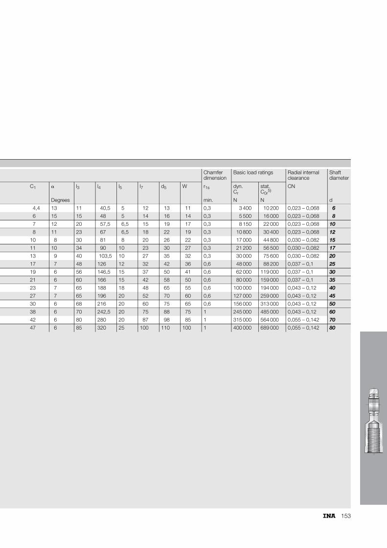
153
Chamfer dimension
Basic load ratings Radial internalclearance
Shaft diameter
C1 � l3 l4 l5 l7 d5 W r1s dyn.Cr
stat.C0r
5)CN
Degrees min. N N d
4,4 13 11 40,5 5 12 13 11 0,3 3 400 10 200 0,023 – 0,068 6
6 15 15 48 5 14 16 14 0,3 5 500 16 000 0,023 – 0,068 8
7 12 20 57,5 6,5 15 19 17 0,3 8 150 22 000 0,023 – 0,068 10
8 11 23 67 6,5 18 22 19 0,3 10 800 30 400 0,023 – 0,068 12
10 8 30 81 8 20 26 22 0,3 17 000 44 800 0,030 – 0,082 15
11 10 34 90 10 23 30 27 0,3 21 200 56 500 0,030 – 0,082 17
13 9 40 103,5 10 27 35 32 0,3 30 000 75 600 0,030 – 0,082 20
17 7 48 126 12 32 42 36 0,6 48 000 88 200 0,037 – 0,1 25
19 6 56 146,5 15 37 50 41 0,6 62 000 119 000 0,037 – 0,1 30
21 6 60 166 15 42 58 50 0,6 80 000 159 000 0,037 – 0,1 35
23 7 65 188 18 48 65 55 0,6 100 000 194 000 0,043 – 0,12 40
27 7 65 196 20 52 70 60 0,6 127 000 259 000 0,043 – 0,12 45
30 6 68 216 20 60 75 65 0,6 156 000 313 000 0,043 – 0,12 50
38 6 70 242,5 20 75 88 75 1 245 000 485 000 0,043 – 0,12 60
42 6 80 280 20 87 98 85 1 315 000 564 000 0,055 – 0,142 70
47 6 85 320 25 100 110 100 1 400 000 689 000 0,055 – 0,142 80
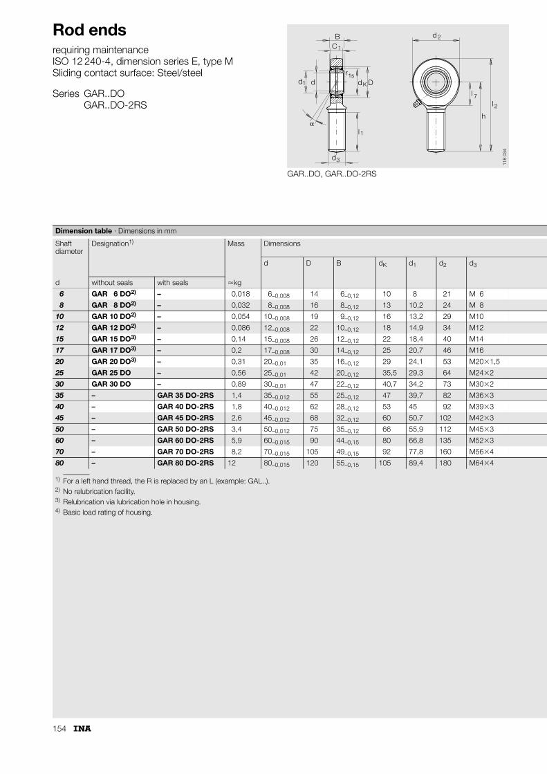
154
Rod endsrequiring maintenanceISO 12 240-4, dimension series E, type MSliding contact surface: Steel/steel
Series GAR..DOGAR..DO-2RS
GAR..DO, GAR..DO-2RS
BC
d
ll
h
rd D
d
d d
1
2
7
2
K
1s
3
�
1
1l
118
034
1) For a left hand thread, the R is replaced by an L (example: GAL..).2) No relubrication facility.3) Relubrication via lubrication hole in housing.4) Basic load rating of housing.
Dimension table · Dimensions in mm
Shaft diameter
Designation1) Mass Dimensions
d D B dK d1 d2 d3
d without seals with seals �kg
6 GAR 6 DO2) – 0,018 6–0,008 14 6–0,12 10 8 21 M 6
8 GAR 8 DO2) – 0,032 8–0,008 16 8–0,12 13 10,2 24 M 8
10 GAR 10 DO2) – 0,054 10–0,008 19 9–0,12 16 13,2 29 M10
12 GAR 12 DO2) – 0,086 12–0,008 22 10–0,12 18 14,9 34 M12
15 GAR 15 DO3) – 0,14 15–0,008 26 12–0,12 22 18,4 40 M14
17 GAR 17 DO3) – 0,2 17–0,008 30 14–0,12 25 20,7 46 M16
20 GAR 20 DO3) – 0,31 20–0,01 35 16–0,12 29 24,1 53 M20�1,5
25 GAR 25 DO – 0,56 25–0,01 42 20–0,12 35,5 29,3 64 M24�2
30 GAR 30 DO – 0,89 30–0,01 47 22–0,12 40,7 34,2 73 M30�2
35 – GAR 35 DO-2RS 1,4 35–0,012 55 25–0,12 47 39,7 82 M36�3
40 – GAR 40 DO-2RS 1,8 40–0,012 62 28–0,12 53 45 92 M39�3
45 – GAR 45 DO-2RS 2,6 45–0,012 68 32–0,12 60 50,7 102 M42�3
50 – GAR 50 DO-2RS 3,4 50–0,012 75 35–0,12 66 55,9 112 M45�3
60 – GAR 60 DO-2RS 5,9 60–0,015 90 44–0,15 80 66,8 135 M52�3
70 – GAR 70 DO-2RS 8,2 70–0,015 105 49–0,15 92 77,8 160 M56�4
80 – GAR 80 DO-2RS 12 80–0,015 120 55–0,15 105 89,4 180 M64�4

155
Chamfer dimension
Basic load ratings Radial internalclearance
Shaft diameter
h C1 � l1 l2 l7 r1s dyn.Cr
stat.C0r
4)CN
Degrees min. N N d
36 4,4 13 18 46,5 12 0,3 3 400 6 920 0,023 – 0,068 6
42 6 15 22 54 14 0,3 5 500 12 900 0,023 – 0,068 8
48 7 12 26 62,5 15 0,3 8 150 20 600 0,023 – 0,068 10
54 8 11 28 71 18 0,3 10 800 30 100 0,023 – 0,068 12
63 10 8 34 83 20 0,3 17 000 41 500 0,030 – 0,082 15
69 11 10 36 92 23 0,3 21 200 56 500 0,030 – 0,082 17
78 13 9 43 104,5 27 0,3 30 000 75 600 0,030 – 0,082 20
94 17 7 53 126 32 0,6 48 000 88 200 0,037 – 0,1 25
110 19 6 65 146,5 37 0,6 62 000 119 000 0,037 – 0,1 30
140 21 6 82 181 42 0,6 80 000 159 000 0,037 – 0,1 35
150 23 7 86 196 48 0,6 100 000 194 000 0,043 – 0,12 40
163 27 7 94 214 52 0,6 127 000 259 000 0,043 – 0,12 45
185 30 6 107 241 60 0,6 156 000 313 000 0,043 – 0,12 50
210 38 6 115 277,5 75 1 245 000 485 000 0,043 – 0,12 60
235 42 6 125 315 87 1 315 000 564 000 0,055 – 0,142 70
270 47 6 140 360 100 1 400 000 689 000 0,055 – 0,142 80

156
Rod endsrequiring maintenanceISO 12 240-4, dimension series K, type FSliding contact surface: Steel/bronze
Series GIKFR..PB
GIKFR..PB
K
3
3 4
5
1s
1
1
2
7
5
14
d d
BC
rd
d
D
l
d
W
dd
l
hl
l
�
118
029
1) For a left hand thread, the R is replaced by an L (example: GIKFL..).2) Bore tolerance: H7 (arithmetic mean value).3) Deviating from ISO 12 240-4, dimension series K.4) No relubrication facility.5) Basic load rating of housing.
Dimension table · Dimensions in mm
Shaft diameter
Designation1) Mass Dimensions
d2) D B dK d1 d2 d3 d4 h1 C1
d �kg
5 GIKFR 5 PB4) 0,016 5+0,012 13 8–0,12 11,112 7,7 18 M 5 8,5 27 6
6 GIKFR 6 PB 0,022 6+0,012 16 9–0,12 12,7 8,9 20 M 6 10 30 6,75
8 GIKFR 8 PB 0,047 8+0,015 19 12–0,12 15,875 10,3 24 M 8 12,5 36 9
10 GIKFR 10 PB 0,077 10+0,015 22 14–0,12 19,05 12,9 28 M10 15 43 10,5
12 GIKFR 12 PB 0,1 12+0,018 26 16–0,12 22,225 15,4 32 M12 17,5 50 12
14 GIKFR 14 PB 0,16 14+0,018 283) 19–0,12 25,4 16,8 36 M14 21 57 13,5
16 GIKFR 16 PB 0,22 16+0,018 32 21–0,12 28,575 19,3 42 M16 22 64 15
18 GIKFR 18 PB 0,32 18+0,018 35 23–0,12 31,75 21,8 46 M18�1,5 25 71 16,5
20 GIKFR 20 PB 0,42 20+0,021 40 25–0,12 34,925 24,3 50 M20�1,5 27,5 77 18
22 GIKFR 22 PB 0,54 22+0,021 42 28–0,12 38,1 25,8 54 M22�1,5 30 84 20
25 GIKFR 25 PB 0,73 25+0,021 47 31–0,12 42,85 29,5 60 M24�2 33,5 94 22
30 GIKFR 30 PB 1,1 30+0,021 55 37–0,12 50,8 34,8 70 M30�2 40 110 25

157
Chamfer dimension
Basic load ratings Radial internalclearance3)
Shaft diameter
� l3 l4 l5 l7 d5 W r1s dyn.Cr
stat.C0r
5)
Degrees min. N N d
13 10 36 4 10 11 9 0,3 3 250 9 180 0 – 0,035 5
13 12 40 5 11 13 11 0,3 4 300 8 000 0 – 0,035 6
14 16 48 5 13 16 14 0,3 7 200 13 100 0 – 0,035 8
13 20 57 6,6 15 19 17 0,3 10 000 18 500 0 – 0,035 10
13 22 66 6,5 17 22 19 0,3 13 400 20 800 0 – 0,035 12
16 25 75 8 18 26 22 0,3 17 000 32 000 0 – 0,035 14
15 28 85 8 23 28 22 0,3 21 600 45 200 0 – 0,035 16
15 32 94 10 25 31 27 0,3 26 000 46 900 0 – 0,035 18
14 33 102 10 26 35 30 0,3 31 500 45 600 0 – 0,035 20
15 37 111 12 29 38 32 0,3 38 000 61 100 0 – 0,035 22
15 42 124 12 32 42 36 0,3 77 500 72 800 0 – 0,035 25
17 51 145 15 37 50 41 0,3 64 000 95 900 0 – 0,035 30
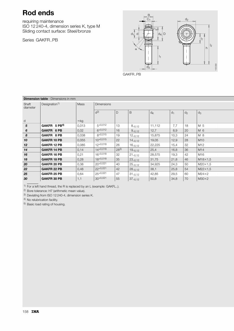
158
Rod endsrequiring maintenanceISO 12 240-4, dimension series K, type MSliding contact surface: Steel/bronze
Series GAKFR..PB
GAKFR..PB
BC1
d1 d K D
d2
r1s
�
l1
d3
l7
hl2
d
118
030
1) For a left hand thread, the R is replaced by an L (example: GAKFL..).2) Bore tolerance: H7 (arithmetic mean value).3) Deviating from ISO 12 240-4, dimension series K.4) No relubrication facility.5) Basic load rating of housing.
Dimension table · Dimensions in mm
Shaft diameter
Designation1) Mass Dimensions
d2) D B dK d1 d2 d3
d �kg
5 GAKFR 5 PB4) 0,013 5+0,012 13 8–0,12 11,112 7,7 18 M 5
6 GAKFR 6 PB 0,02 6+0,012 16 9–0,12 12,7 8,9 20 M 6
8 GAKFR 8 PB 0,038 8+0,015 19 12–0,12 15,875 10,3 24 M 8
10 GAKFR 10 PB 0,055 10+0,015 22 14–0,12 19,05 12,9 28 M10
12 GAKFR 12 PB 0,085 12+0,018 26 16–0,12 22,225 15,4 32 M12
14 GAKFR 14 PB 0,14 14+0,018 283) 19–0,12 25,4 16,8 36 M14
16 GAKFR 16 PB 0,21 16+0,018 32 21–0,12 28,575 19,3 42 M16
18 GAKFR 18 PB 0,28 18+0,018 35 23–0,12 31,75 21,8 46 M18�1,5
20 GAKFR 20 PB 0,38 20+0,021 40 25–0,12 34,925 24,3 50 M20�1,5
22 GAKFR 22 PB 0,48 22+0,021 42 28–0,12 38,1 25,8 54 M22�1,5
25 GAKFR 25 PB 0,64 25+0,021 47 31–0,12 42,85 29,5 60 M24�2
30 GAKFR 30 PB 1,1 30+0,021 55 37–0,12 50,8 34,8 70 M30�2

159
Chamfer dimension
Basic load ratings Radial internalclearance3)
Shaft diameter
h C1 � l1 l2 l7 r1s dyn.Cr
stat.C0r
5)
Degrees min. N N d
33 6 13 19 42 – 0,3 3 250 4 890 0 – 0,035 5
36 6,75 13 21 46 – 0,3 4 300 6 920 0 – 0,035 6
42 9 14 25 54 – 0,3 7 200 12 900 0 – 0,035 8
48 10,5 13 28 62 – 0,3 10 000 18 500 0 – 0,035 10
54 12 13 32 70 – 0,3 13 400 20 800 0 – 0,035 12
60 13,5 16 36 78 18 0,3 17 000 32 000 0 – 0,035 14
66 15 15 37 87 23 0,3 21 600 45 200 0 – 0,035 16
72 16,5 15 41 95 25 0,3 26 000 46 900 0 – 0,035 18
78 18 14 45 103 26 0,3 31 500 45 600 0 – 0,035 20
84 20 15 48 111 29 0,3 38 000 61 100 0 – 0,035 22
94 22 15 55 124 32 0,3 47 500 72 800 0 – 0,035 25
110 25 17 66 145 37 0,3 64 000 95 900 0 – 0,035 30

160
Hydraulic rod endsrequiring maintenanceDIN 24338, ISO 6982Sliding contact surface: Steel/steel
Series GIHN-K..LO
GIHN-K..LO (d � 50 mm)
BC
r
d D
d
ll
h
Section
C
Md
l
dd
d d
1
1s 5)
K
3
3
4
1
2
74
1
2
A
5
�
118
026
1) Bore tolerance: H7 (arithmetic mean value).2) No relubrication facility.3) Not included in DIN 24 338.4) Cylindrical throughout.5) Values in dimension table, page 113.6) Thread runout or thread groove at manufacturer's discretion.7) Price and delivery on request.8) Basic load rating of housing.
Dimension table · Dimensions in mm
Shaft diameter
Designation1) Mass Dimensions
d2) D B dK d1 d2 d3 d4 h1 C1
d �kg
12 GIHN-K 12 LO2)4) 0,1 12+0,018 22 12–0,18 18 15,5 32 M 12�1,25 16,5 38 10,6
16 GIHN-K 16 LO4) 0,2 16+0,018 28 16–0,18 23 20 40 M 14�1,5 21 44 13
20 GIHN-K 20 LO 0,4 20+0,021 35 20–0,21 29 25 47 M 16�1,5 25 52 17
25 GIHN-K 25 LO 0,66 25+0,021 42 25–0,21 35,5 30,5 58 M 20�1,5 30 65 21
32 GIHN-K 32 LO 1,2 32+0,025 52 32–0,25 44 38 70 M 27�2 38 80 27
40 GIHN-K 40 LO6) 2,1 40+0,025 62 40–0,25 53 46 89 M 33�2 47 97 32
50 GIHN-K 50 LO6) 4,4 50+0,025 75 50–0,25 66 57 108 M 42�2 58 120 40
63 GIHN-K 63 LO6) 7,6 63+0,03 95 63–0,3 83 71,5 132 M 48�2 70 140 52
70 GIHN-K 70 LO3)6)7) 9,5 70+0,03 105 70–0,3 92 79 155 M 56�2 80 160 57
80 GIHN-K 80 LO6) 14,5 80+0,03 120 80–0,3 105 91 168 M 64�3 90 180 66
90 GIHN-K 90 LO3)6) 17 90+0,035 130 90–0,35 115 99 185 M 72�3 100 195 72
100 GIHN-K 100 LO 28 100+0,035 150 100–0,35 130 113 210 M 80�3 110 210 84
110 GIHN-K 110 LO3) 32 110+0,035 160 110–0,35 140 124 235 M 90�3 125 235 88
125 GIHN-K 125 LO 43 125+0,04 180 125–0,4 160 138 262 M100�3 135 260 102
160 GIHN-K 160 LO7) 80 160+0,04 230 160–0,4 200 177 326 M125�4 165 310 130
200 GIHN-K 200 LO7) 165 200+0,046 290 200–0,46 250 221 418 M160�4 215 390 162
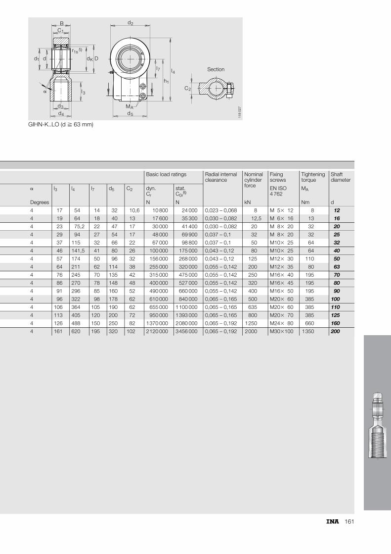
161
GIHN-K..LO (d � 63 mm)
BC
r
d D
d
l l
h
Section
C
Md
l
dd
d d
1
1s 5)
K
3
3
4
1
2
74
1
2
A
5
�
118
027
Basic load ratings Radial internalclearance
Nominal cylinder force
Fixingscrews
Tightening torque
Shaft diameter
� l3 l4 l7 d5 C2 dyn.Cr
stat.C0r
8)EN ISO4 762
MA
Degrees N N kN Nm d
4 17 54 14 32 10,6 10 800 24 000 0,023 – 0,068 8 M 5� 12 8 12
4 19 64 18 40 13 17 600 35 300 0,030 – 0,082 12,5 M 6� 16 13 16
4 23 75,2 22 47 17 30 000 41 400 0,030 – 0,082 20 M 8� 20 32 20
4 29 94 27 54 17 48 000 69 900 0,037 – 0,1 32 M 8� 20 32 25
4 37 115 32 66 22 67 000 98 800 0,037 – 0,1 50 M10� 25 64 32
4 46 141,5 41 80 26 100 000 175 000 0,043 – 0,12 80 M10� 25 64 40
4 57 174 50 96 32 156 000 268 000 0,043 – 0,12 125 M12� 30 110 50
4 64 211 62 114 38 255 000 320 000 0,055 – 0,142 200 M12� 35 80 63
4 76 245 70 135 42 315 000 475 000 0,055 – 0,142 250 M16� 40 195 70
4 86 270 78 148 48 400 000 527 000 0,055 – 0,142 320 M16� 45 195 80
4 91 296 85 160 52 490 000 660 000 0,055 – 0,142 400 M16� 50 195 90
4 96 322 98 178 62 610 000 840 000 0,065 – 0,165 500 M20� 60 385 100
4 106 364 105 190 62 655 000 1100 000 0,065 – 0,165 635 M20� 60 385 110
4 113 405 120 200 72 950 000 1393 000 0,065 – 0,165 800 M20� 70 385 125
4 126 488 150 250 82 1370 000 2080 000 0,065 – 0,192 1250 M24� 80 660 160
4 161 620 195 320 102 2120 000 3456 000 0,065 – 0,192 2000 M30�100 1350 200

162
Hydraulic rod endsrequiring maintenanceSliding contact surface: Steel/steel
Series GIHR-K..DO
GIHR-K..DO (d � 50 mm)
B
C
r
d D
d
l l
h
Section
d
l
dd
d d
1
1s 1)
K
3
3
4
1
2
7 4
1
5
�
118
045
For rod ends of sizes 20 mm, 25 mm and 30 mm, thread runout to DIN 76.
1) Values in dimension table, page 107.2) Basic load rating of housing.3) These hydraulic rod ends are also available with
maintenance-free spherical plain bearings GE..UK, GE..UK-2RS, GE..FW, GE..FW-2RS.
In this case, the basic dynamic load ratings Cr then correspond to the values on page 77 and 81.
Dimension table · Dimensions in mm
Shaft diameter
Designation3) Mass Dimensions
d D B dK d1 d2 d3 d4
d �kg
20 GIHR-K 20 DO 0,43 20–0,01 35 16–0,12 29 24,1 56 M 16�1,5 25
25 GIHR-K 25 DO 0,48 25–0,01 42 20–0,12 35,5 29,3 56 M 16�1,5 25
30 GIHR-K 30 DO 0,74 30–0,01 47 22–0,12 40,7 34,2 64 M 22�1,5 32
35 GIHR-K 35 DO 1,2 35–0,012 55 25–0,12 47 39,7 78 M 28�1,5 40
40 GIHR-K 40 DO 2 40–0,012 62 28–0,12 53 45 94 M 35�1,5 49
50 GIHR-K 50 DO 3,8 50–0,012 75 35–0,12 66 55,9 116 M 45�1,5 61
60 GIHR-K 60 DO 5,4 60–0,015 90 44–0,15 80 66,8 130 M 58�1,5 75
70 GIHR-K 70 DO 8,5 70–0,015 105 49–0,15 92 77,8 154 M 65�1,5 86
80 GIHR-K 80 DO 12 80–0,015 120 55–0,15 105 89,4 176 M 80�2 102
90 GIHR-K 90 DO 21,5 90–0,02 130 60–0,2 115 98,1 206 M100�2 124
100 GIHR-K 100 DO 27,5 100–0,02 150 70–0,2 130 109,5 230 M110�2 138
110 GIHR-K 110 DO 40,5 110–0,02 160 70–0,2 140 121,2 265 M120�3 152
120 GIHR-K 120 DO 76 120–0,02 180 85–0,2 160 135,5 340 M130�3 172

163
GIHR-K..DO (d � 60 mm)
B
C
r
d D
d
l l
h
Section
d
l
dd
d d
1
1s 1)
K
3
3
4
1
2
7 4
1
5
�
118
044
Basic load ratings Radial internalclearance
Fixing screws
Tightening torque
Shaft diameter
h1 � l3 l4 l7 d5 C1 dyn.Cr
stat.C0r
2)CN EN ISO
4 762MA
Degrees N N Nm d
50 9 17 78 25 41 19 30 000 81 100 0,030 – 0,082 M 8�20 32 20
50 7 17 78 25 41 23 48 000 65 400 0,037 – 0,1 M 8�25 32 25
60 6 23 92 30 46 28 62 000 96 700 0,037 – 0,1 M 8�25 32 30
70 6 29 109 38 58 30 80 000 140 000 0,037 – 0,1 M10�30 64 35
85 7 36 132 45 66 35 100 000 227 000 0,043 – 0,12 M10�35 64 40
105 6 46 163 55 88 40 156 000 333 000 0,043 – 0,12 M12�35 110 50
130 6 59 200 65 90 50 245 000 326 000 0,043 – 0,12 M10�45 46 60
150 6 66 232 75 100 55 315 000 440 000 0,055 – 0,142 M12�50 80 70
170 6 81 265 80 125 60 400 000 550 000 0,055 – 0,142 M16�50 195 80
210 5 101 323 90 146 65 490 000 810 000 0,055 – 0,142 M16�60 195 90
235 7 111 360 105 166 70 610 000 920 000 0,065 – 0,165 M20�60 385 100
265 6 125 407,5 115 190 80 655 000 1382 000 0,065 – 0,165 M20�70 385 110
310 6 135 490 140 217 90 950 000 2373 000 0,065 – 0,165 M24�80 660 120

164
Hydraulic rod endsrequiring maintenanceISO 12 240-4, dimension series E, type SSliding contact surface: Steel/steel
Series GK..DO
GK..DO
BC1
d1 d K D
d2
l7l6
h2
d6
r1s
�
45˚
l86
d7
d
118
039
1) No relubrication facility.2) Relubrication via lubrication hole in housing.3) Basic load rating of housing.4) Price and delivery on request.5) Deviating from ISO 12 240-4.
Dimension table · Dimensions in mm
Shaft diameter
Designation Mass Dimensions
d D B dK d1 d2 d6 h2
d �kg
10 GK 10 DO1)4) 0,041 10–0,008 19 9–0,12 16 13,2 29 15 24
12 GK 12 DO1)4) 0,066 12–0,008 22 10–0,12 18 14,9 34 17,5 27
15 GK 15 DO2)4) 0,12 15–0,008 26 12–0,12 22 18,4 40 21 31
17 GK 17 DO2) 0,19 17–0,008 30 14–0,12 25 20,7 46 24 35
20 GK 20 DO2) 0,23 20–0,01 35 16–0,12 29 24,1 53 27,5 38
25 GK 25 DO 0,43 25–0,01 42 20–0,12 35,5 29,3 64 33,5 45
30 GK 30 DO 0,64 30–0,01 47 22–0,12 40,7 34,2 73 40 51
35 GK 35 DO 0,96 35–0,012 55 25–0,12 47 39,7 82 47 61
40 GK 40 DO 1,3 40–0,012 62 28–0,12 53 45 92 52 69
45 GK 45 DO 1,8 45–0,012 68 32–0,12 60 50,7 102 58 77
50 GK 50 DO 2,5 50–0,012 75 35–0,12 66 55,9 112 62 88
60 GK 60 DO 3,9 60–0,015 90 44–0,15 80 66,8 135 70 100
70 GK 70 DO 6,6 70–0,015 105 49–0,15 92 77,8 160 80 115
80 GK 80 DO 8,7 80–0,015 120 55–0,15 105 89,4 180 95 141

165
Chamfer dimension
Basic load ratings Radial internalclearance5)
Shaft diameter
C1 � l6 l7 l8 d7 r1s dyn.Cr
stat.C0r
3)CN
Degrees min. N N d
7 12 38,5 15 2 3 0,3 8 150 15 600 0,023 – 0,068 10
8 11 44 18 2 3 0,3 10 800 21 500 0,023 – 0,068 12
10 8 51 20 2,5 4 0,3 17 000 31 800 0,030 – 0,082 15
11 10 58 23 3 4 0,3 21 200 40 100 0,030 – 0,082 17
13 9 64,5 27 3 4 0,3 30 000 52 400 0,030 – 0,082 20
17 7 77 32 4 4 0,6 48 000 70 800 0,037 – 0,1 25
19 6 87,5 37 4 4 0,6 62 000 95 600 0,037 – 0,1 30
21 6 102 42 4 4 0,6 80 000 127 000 0,037 – 0,1 35
23 7 115 48 5 4 0,6 100 000 155 000 0,043 – 0,12 40
27 7 128 52 5 6 0,6 127 000 208 000 0,043 – 0,12 45
30 6 144 60 6 6 0,6 156 000 251 000 0,043 – 0,12 50
38 6 167,5 75 8 6 1 245 000 389 000 0,043 – 0,12 60
42 6 195 87 10 6 1 315 000 510 000 0,055 – 0,142 70
47 6 231 100 10 6 1 400 000 624 000 0,055 – 0,142 80
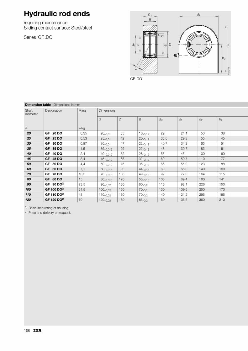
166
Hydraulic rod endsrequiring maintenanceSliding contact surface: Steel/steel
Series GF..DO
GF..DO
B
C1
d1 d K D
d2
l6
h2
r1s
�
d
118
040
1) Basic load rating of housing.2) Price and delivery on request.
Dimension table · Dimensions in mm
Shaft diameter
Designation Mass Dimensions
d D B dK d1 d2 h2
d �kg
20 GF 20 DO 0,35 20–0,01 35 16–0,12 29 24,1 50 38
25 GF 25 DO 0,53 25–0,01 42 20–0,12 35,5 29,3 55 45
30 GF 30 DO 0,87 30–0,01 47 22–0,12 40,7 34,2 65 51
35 GF 35 DO 1,5 35–0,012 55 25–0,12 47 39,7 83 61
40 GF 40 DO 2,4 40–0,012 62 28–0,12 53 45 100 69
45 GF 45 DO 3,4 45–0,012 68 32–0,12 60 50,7 110 77
50 GF 50 DO 4,4 50–0,012 75 35–0,12 66 55,9 123 88
60 GF 60 DO 7,1 60–0,015 90 44–0,15 80 66,8 140 100
70 GF 70 DO 10,5 70–0,015 105 49–0,15 92 77,8 164 115
80 GF 80 DO 15 80–0,015 120 55–0,15 105 89,4 180 141
90 GF 90 DO2) 23,5 90–0,02 130 60–0,2 115 98,1 226 150
100 GF 100 DO2) 31,5 100–0,02 150 70–0,2 130 109,5 250 170
110 GF 110 DO2) 48 110–0,02 160 70–0,2 140 121,2 295 185
120 GF 120 DO2) 79 120–0,02 180 85–0,2 160 135,5 360 210

167
Chamfer dimension
Basic load ratings Radial internalclearance
Shaft diameter
C1 C1 a l6 r1s dyn.Cr
stat.C0r
1)CN
nominal max. Degrees min. N N d
19 20 9 63 0,3 30 000 65 500 0,030 – 0,082 20
23 24 7 72,5 0,6 48 000 68 700 0,037 – 0,1 25
28 29 6 83,5 0,6 62 000 115 000 0,037 – 0,1 30
30 31 6 102,5 0,6 80 000 193 000 0,037 – 0,1 35
35 36,5 7 119 0,6 100 000 305 000 0,043 – 0,12 40
40 41,5 7 132 0,6 127 000 386 000 0,043 – 0,12 45
40 41,5 6 149,5 0,6 156 000 441 000 0,043 – 0,12 50
50 52,5 6 170 1 245 000 558 000 0,043 – 0,12 60
55 58 6 197 1 315 000 724 000 0,055 – 0,142 70
60 63 6 231 1 400 000 804 000 0,055 – 0,142 80
65 69 5 263 1 490 000 1 352 000 0,055 – 0,142 90
70 74 7 295 1 610 000 1 516 000 0,065 – 0,165 100
80 85 6 332,5 1 655 000 2 340 000 0,065 – 0,165 110
90 95 6 390 1 950 000 3 510 000 0,065 – 0,165 120

168
Other products
Other products in the range:■ are special products which differ from the catalogue range in
type and design■ are products for special bearing arrangement problems■ are produced exclusively for specific customers or orders.In order to achieve the most favourable solution in technical and economic terms using products from this range, the development should be discussed and agreed as early as possible in the project with the manufacturer's engineering service.
Special rod ends■ comprise a rod end and spherical plain bearing whose
inner ring is in the form of a mounting lug■ can be combined with a hydraulic rod end, for example
for fitting on the piston side to a hydraulic cylinder■ are made from high strength forged materials■ are easy to fit and service – the lug is fixed to the moving part
by cap head screws■ can be quickly and easily fitted and are more easily
dismantled than conventional pin arrangements due to the screw connection
■ require no precision fixtures, shafts or anti-rotation devices on the customer's part (leading to cost savings).
Locating bearings for articulated frame steering■ are used as locating bearings in frame steering systems
for construction machinery■ can support high radial and axial loads■ have sliding zones of a special geometrical design.
This prevents edge stresses in the part of the bearing under axial load
■ are supplied preadjusted. There is therefore no need for clearance adjustment by the customer.
Figure 1 · Special rod end
Figure 2 · Locating bearings for articulated frame steering
117
140
117
141

169
Prop shaft centring bearings■ are movable cardanic centring elements■ are used to damp vibrations in rear and four wheel drive
vehicles in the centre of the coupling between the gearbox and prop shaft
■ support the prop shaft mass on the coupling, preventing eccentricity of the elastically coupled shafts.
Flanged spherical plain bearings■ are used in clutch actuation systems■ are maintenance-free.
Joint connecting rods■ are used in brake actuation systems■ contain maintenance-free spherical plain bearings.
Figure 3 · Prop shaft centring bearings
Figure 4 · Flanged spherical plain bearings
Figure 5 · Joint connecting rod
117
142
117
218
117
217

170
Other products
Spherical plain bearings for clearance-free bearing arrangements■ are used in clearance-free bearing arrangements for control
elements such as gear levers■ have a plastic/steel sliding contact surface■ compensate wear up to 0,4 mm due to the use of preloaded
rubber elements■ have preload values comparable to a new bearing even after
a long operating life■ are maintenance-free throughout their operating life after
initial greasing.
Gear lever bearing arrangements■ are developed to meet the specific requirements of
the vehicle manufacturer■ give continuous compensation of the operating clearance■ have a constant tilting moment■ are maintenance-free for the life of the vehicle■ can be combined with noise and vibration damping
measures.
Brake pedal linkages■ are spherical plain bearing units■ connect the brake pedal to the brake servo unit■ give positive transmission of the brake pedal stroke and
pedal force moment-free by means of a coupling on both sides
■ have a rod end at one end fixed to the aluminium linkage rod to prevent rotation
■ have a rod end on the other end with a thread for adjusting the rod length. The set position is then fixed using a locknut. A sheet metal safety lug is formed about the pressure pipe and spot welded.
Figure 6 · Spherical plain bearings for clearance-free bearing arrangements
Figure 7 · Gear lever bearing arrangement
Figure 8 · Brake pedal linkage
117
145a
117
146
117
147

171

172

173

174

175

176

CD
medias® professional
199
128a

Each section in Catalogue 238 begins with a description of the product series and their features.The essential characteristics of the spherical plain bearings, maintenance-free plain bushes and rod ends are indicated by means of pictograms.
The advantages of this type of presentation include:■ less reading is required■ the required information can be accessed more quickly■ a direct comparison between alternative bearings is
possible.
Definition of pictograms
Pictogram Description
The spherical plain bearings can perform spatial oscillating motion even under load
The rod ends can perform spatial oscillating motion even under load
The bearings can support radial forces
The bearings can support axial forces in one direction
The bearings are greased
The bearings can be relubricated
The bearings are sealed on both sides
The permissible operating temperature differs from the standard values
This pictogram indicates the dimension table
If this information is not adhered to, there is a direct or indirect risk to the product and/or the adjacent construction
˚C
70

Schaeffler KG
Industriestrasse 1–3
91074 Herzogenaurach (Germany)
Internet www.ina.com
E-Mail [email protected]
In Germany:
Phone 0180 5003872
Fax 0180 5003873
From Other Countries:
Phone +49 9132 82-0
Fax +49 9132 82-4950
Every care has been taken to ensure the
correctness of the information contained
in this publication but no liability can be
accepted for any errors or omissions.
We reserve the right to make technical
changes.
© Schaeffler KG · 2008, February
This publication or parts thereof may not
be reproduced without our permission.
238 GB-DMA
TNR
0020
5072
2-00
00 /
238
/ G
B-D
/ 2
0080
22 /
Pri
nted
in G
erm
any
by H
ofm
ann
Dru
ck

Cat
alo
gue
238
S
phe
rica
l pla
in b
eari
ngs
· Pla
in b
ushe
s · R
od
end
s