spent fuel management: current status and prospects 1993
TRANSCRIPT

IAEA-TECDOC-732
Spent fuel management:Current status and prospects
1993Proceedings of a Regular Advisory Group meeting
held in Vienna, 31 August-3 September 1993
February 1994

The originating Section of this document in the IAEA was:
Nuclear Materials and Fuel Cycle Technology SectionInternational Atomic Energy Agency
Wagramerstrasse 5P.O. Box 100
A-1400 Vienna, Austria
SPENT FUEL MANAGEMENT: CURRENT STATUS AND PROSPECTS 1993IAEA, VIENNA, 1994IAEA-TECDOC-732
ISSN 1011-4289
Printed by the IAEA in AustriaFebruary 1994

The IAEA does not normally maintain stocks of reports in this series.However, microfiche copies of these reports can be obtained from
INIS ClearinghouseInternational Atomic Energy AgencyWagramerstrasse 5P.O. Box 100A-1400 Vienna, Austria
Orders should be accompanied by prepayment of Austrian Schillings 100,in the form of a cheque or in the form of IAEA microfiche service couponswhich may be ordered separately from the INIS Clearinghouse.

FOREWORD
Spent fuel management has always been one of the most important stages in the nuclearfuel cycle and it is still one of the most vital problems common to all countries with nuclearreactors. It begins with the discharge of spent fuel from a power or a research reactor andends with its ultimate disposition, either by direct disposal or by reprocessing of the spentfuel. Two options exist at present — an open, once-through cycle with direct disposal of thespent fuel and a closed cycle with reprocessing of the spent fuel and recycling of plutoniumand uranium in new mixed oxide fuels. The selection of a spent fuel strategy is a complexprocedure in which many factors have to be weighed, including political, economic andsafeguards issues as well as protection of the environment.
Delays hi the implementation of the fuel reprocessing option in some countries, thecomplete abandonment of this option hi other countries and delays hi the availability of finalspent fuel disposal in almost all countries has led to increasingly long periods of interimspent fuel storage. This wait and see approach gives more time and freedom to evaluate theavailable options and to select the most suitable technology. The problem of spent fuelmanagement has therefore increased in importance for many countries.
Continuous attention is being given by the IAEA to the collection, analysis andexchange of information on spent fuel management. Its role in this area is to provide aforum for the exchange of information and to co-ordinate and to encourage closer co-operation among Member States in certain research and development activities that are ofcommon interest. Spent fuel management is recognized by the IAEA as a high priorityactivity.
The Regular Advisory Group on Spent Fuel Management was established in accordancewith the recommendations of the Expert Group on International Spent Fuel Management in1982. It has held meetings in 1984, 1986, 1988 1990 and 1991. The Regular Advisory Groupconsists of nominated experts from the Member States with considerable experience and/orrequirements in spent fuel management. The country membership is selected in a such amanner as to reflect the various spent fuel policies ranging from the closed fuel cycle toonce-through concepts and includes representatives from both the developed and thedeveloping nuclear power users.
The objective of the Regular Advisory Group is to serve as a means of exchanginginformation on the current status and progress of national programmes on spent fuelmanagement and to provide advice to the IAEA.
The results of the last Regular Advisory Group meeting (31 August-3 September 1993)are reflected in this document. It gives an overview of the status of spent fuel managementprogrammes in a number of countries and a description of the past and present IAEAactivities in this field and the IAEA's plans for the next years, based on the proposals andrecommendations of Member States.
The IAEA wishes to thank all participants of the Regular Advisory Group meeting fortheir fruitful contributions and especially the Chairman, Mr. J.R. Williams. The ScientificSecretaries of the IAEA responsible for the organization of the meeting and for this documentwere Messrs F. Takâts and A. Grigoriev of the Nuclear Materials and Fuel CycleTechnology Section, Division of Nuclear Fuel Cycle and Waste Management.

EDITORIAL NOTE
In preparing this document for press, staff of the IAEA have made up the pages from theoriginal manuscripts as submitted by the authors. The views expressed do not necessarily reflect thoseof the governments of the nominating Member States or of the nominating organizations.
The use of particular designations of countries or territories does not imply any judgement bythe publisher, the IAEA, as to the legal status of such countries or territories, of their authorities andinstitutions or of the delimitation of their boundaries.
The mention of names of specific companies or products (whether or not indicated as registered)does not imply any intention to infringe proprietary rights, nor should it be construed as anendorsement or recommendation on the part of the IAEA.
The authors are responsible for having obtained the necessary permission for the IAEA toreproduce, translate or use material from sources already protected by copyrights.
CONTENTS
Summary of the Advisory Group meeting . . . . . . . . . . . . . . . . . . . . . . . . . . . 7
Used nuclear fuel management in Canada . . . . . . . . . . . . . . . . . . . . . . . . . . . 11P.A. Brown, G.A. Underdown
An update on used fuel management in Canada . . . . . . . . . . . . . . . . . . . . . . . 17S.J. Naqvi, C.R Frost
Spent fuel management in France: Current status and prospects . . . . . . . . . . . . . . 29D. Gerster
LWR spent fuel management in the Federal Republic of Germany . . . . . . . . . . . . 39M. Peeks
Spent fuel management in Hungary: Present status and progress in the back-endof the nuclear fuel cycle . . . . . . . . . . . . . . . . . . . . . . . . . . . . . . . . . . . 45G. Ferenczi
Spent fuel management in India: A review . . . . . . . . . . . . . . . . . . . . . . . . . . 49D.D. Bajpai
Spent fuel management in Japan . . . . . . . . . . . . . . . . . . . . . . . . . . . . . . . . 53Y. Maruyama, M. Maeda, T. Shimizu
Spent fuel management in the Republic of Korea: Past, present and future . . . . . . . 67Won J. Park
Reprocessing and fate of long-lived radionuclides . . . . . . . . . . . . . . . . . . . . . . 75V.N. Romanovskij
Spent fuel management in the Russian Federation: State of the art and outlookfor the future . . . . . . . . . . . . . . . . . . . . . . . . . . . . . . . . . . . . . . . . . . 83V.V. Morozov, V.V. Spichev, N.S. Tikhonov, S.V. Shishkin
Spent fuel management in the Slovak Republic . . . . . . . . . . . . . . . . . . . . . . . . 95/. Kmosena
Swedish spent fuel management; systems, facilities and operating experiences . . . . . 101J. Vogt
Spent fuel management in Switzerland . . . . . . . . . . . . . . . . . . . . . . . . . . . . . 1 1 1C. Ospina
Status report on spent fuel management in the United Kingdom - August 1993 . . . . 115R. Dodds
United States high-level radioactive waste management program: Current statusand plans . . . . . . . . . . . . . . . . . . . . . . . . . . . . . . . . . . . . . . . . . . . . 119/. Williams
List of Participants . . . . . . . . . . . . . . . . . . . . . . . . . . . . . . . . . . . . . . . . 129

SUMMARY OF THE ADVISORY GROUP MEETING
Current status and prospects
The Advisory Group observed that the activities related to the management of spentnuclear fuel continue to be of high priority in assuring the safe use of nuclear energy. It wasobserved that the spent fuel management (SFM) strategy adopted by each country dependsupon many factors which are country specific.
It was observed that the different SFM programmes are being pursued as follows:
Countries actively operating or constructing reprocessing plants (e.g. France, Japan,India, Russia and United Kingdom);
Countries that have contracts for reprocessing abroad (e.g. Belgium, Germany, Japan,Finland, Netherlands, Switzerland);
Countries that are following the once-through fuel cycle (e.g. Canada, Sweden, USA)and focusing their attention on interim storage followed by disposal of the fuel or longterm storage if necessary;
Countries that have nuclear power and are still evaluating the SFM options (e.g.Republic of Korea). Some of the east European countries (e.g. Hungary and the SlovakRepublic) have uncertainties in shipping back spent fuel to Russia. Therefore, a newback-end strategy is being developed. In the meantime, they are planning to constructaway from reactor (APR) storage facilities.
A common feature of most national situations, independent of the fuel cycle back-endoptions, is the ongoing need for additional storage.
It was noted that while there remain challenges in the area of spent fuel management,much progress has been made. The review of national programmes shows that:
Handling, storage and transport of spent fuel are continuously taking place safely;
Additional wet and dry spent fuel storage facilities have been designed, constructed,licensed and are being operated safely;
Both commercial and prototype reprocessing facilities continue to operate satisfactorily.
While reviewing activities in the represented countries it was observed that thé differentSFM programmes are subject to economic, technological and policy changes.
Examples of developments that have taken place since the 1991 Advisory Groupmeeting are as follows:
Most countries are either constructing or planning to construct additional spent fuelstorage facilities (e.g. APR storage facilities);
The main new design concept for both interim and long-term storage is dry;

Two countries (Russia and the United Kingdom) with major reprocessing plants inoperation are also considering direct disposal of some of their spent fuel arisings;
Most countries with reprocessing facilities are developing programmes to minimizevolumes and radioactivities of ultimate wastes;
Interest hi rod consolidation for storage has diminished.
Advisory group recommendations
The Advisory Group concluded the meeting with a panel discussion which reviewed theactivities and trends observed during the course of the meeting. It was especially noted thatthe back-end of the fuel cycle is a maturing technology and no major changes in the IAEAprogramme currently appear to be necessary. The following comments summarize theGroup's recommendations:
The Advisory Group recommends that the various national and international activitiesin spent fuel management should be co-ordinated and/or combined in order to avoidduplication of efforts. Therefore, it was recommended that attention be focused uponthose areas where international co-operation would prove to be effective.
It was noted that the total number of operating nuclear power reactors at the end of1992 in the world is 424, the total amount of worldwide spent fuel cumulated at the endof 1992 is 125 000 t HM and projections indicate that the cumulative amount of spentfuel by the year 2000 may reach 225 000 t HM. As part of it is to be reprocessed, theamount of spent fuel to be stored by the year 2000 is expected to be about 150 000 tHM. Recognizing the significance of the spent fuel and waste generated by these andfuture nuclear power plants, the Group endorsed the continuing encouragement andsupport for the study of the issues arising from the treatment, transport, storage andconditioning of this fuel.
The Advisory Group noted that there is increasing use of existing spent fuel storagefacilities and/or an increase of the capacity of these facilities. Thus, it is important thatthe operational aspects as well as design and development activities be discussed anddocumented as experience is gained with the safe storage, handling and transport ofspent fuel including the reduction of the volume of spent fuel.
The Advisory Group recognizes that taking credit for fuel burnup and the possiblesignificance of integrated burnable absorbers could have the advantage to increase thecapacity of storage facilities and transport casks. The Advisory Group recommends thisaspect to be further investigated.
Since some countries have chosen long term storage in casks with a requirement foreventual transportation, it is recommended to continue the activity related to integratedsystems for both storage and transportation.
The Advisory Group notes that although transport of spent fuel is addressed elsewherein the IAEA, it is recommended that consideration should be given to possible interfaceissues. An example for consideration would be the preparation of spent fuel fortransportation and related quality assurance.

The Advisory Group noted that the number of additional dry storage facilities requiredwill be increased significantly hi the near term. The Group reviewed the proposedprogramme and concurred that the programme appropriately addresses this importantdevelopment.
The Advisory Group continues to recognize the importance of relevant spent fuel datadocumentation of medium and long term storage. The Group notes that therecommendations from the October 1991 meeting to develop a spent fuel database wereimplemented. This work is continuing under the IAEA's programme and is believed tobe appropriately addressed.
The Advisory Group recommends to continue the studies related to the long termstability of spent fuel assemblies and storage equipments and long term storageconditions.
The Advisory Group discussed problems related to the management of spent fuel fromresearch reactors. The group then reviewed the programme related to this subject andagreed that the tasks planned appropriately address the situation and will providevaluable information to Member States.
The Advisory Group recognizes that the IAEA followed the recommendation to supportthe developing countries programme by an increasing number of missions in aframework of Irradiated Fuel Management Advisory Programme. Therefore theAdvisory Group supports this activity.
The Advisory Group noted that new research and development programmes aimed atminimization of arisings in the back-end of the closed fuel cycle (recycling andreprocessing) are currently under development in some countries. Therefore, the grouptakes note of the increasing activity in this field and recommends to keep this activityunder review.
Next page(s) left blank
USED NUCLEAR FUEL MANAGEMENT IN CANADA
P.A. BROWN, G.A. UNDERDOWNRadioactive Waste and Radiation Electricity Branch,Energy, Mines and Resources,Ottawa, Canada
Abstract
Canada has a nuclear fuel cycle based on a unique reactor system, the CANDU, developed by theCrown Corporation, Atomic Energy of Canada Limited (AECL), which uses natural uranium in a once-throughfuel cycle. Canada's nuclear power program is sixth in the world hi terms of electricity generated. This paperprovides an overview of Canada's approach to the management of radioactive wastes arising from its nuclearactivities, with particular emphasis on the management of used nuclear fuel (high level radioactive) waste. Ingeneral, the approach to radioactive waste management integrates the requirements for appropriate and safetechnology, effective regulation, and public participation.
1. INTRODUCTION
The management and disposal of used fuel from nuclear reactors has long been acentral issue in the debate surrounding nuclear power. In 1977, after several years ofresearch, a federal task group was formed to address options for the long-term managementof used nuclear fuel wastes in Canada. The resulting report by Kenneth Hare titled "TheManagement of Canada's Nuclear Wastes" recommended that geological disposal incrystalline igneous rock of the Canadian Shield be further investigated, focusing Canada'sresearch resources on a single concept.
This led to the establishment of the Canadian Nuclear Fuel Waste ManagementProgram by the governments of Canada and Ontario in 1978. The program's mandate is toresearch, develop, and assess a geologic disposal concept for Canada. AECL has theresponsibility for developing immobilization and disposal technology, while Ontario Hydrohas responsibility for storage and transportation technology.
The disposal concept currently assumes a period of 30 years after concept acceptanceto perform site screening, site characterization (both surface and underground), andconstruction of a disposal vault; a period of 40 years to fill the vault, during whichcontinuous monitoring will take place; and backfilling and sealing of the vault once generalconfidence in the integrity of the facility has been established.
2. PUBLIC ACCEPTANCE AND THE ENVIRONMENTAL THRUSTThe nuclear fuel cycle has been for many years, and still is, subject to intense
scrutiny by the media and the public in Canada as elsewhere in the world. It has become atruism that the future of nuclear power will depend on public acceptance. In turn, publicacceptance will be based on perceptions of the relative health and environmental impact ofnuclear power at all stages in the nuclear fuel cycle.
What is new in recent years is that other sources of energy and electricity areincreasingly subject to a level of public examination that was once reserved for the nuclearoption. Perhaps this will allow for a more balanced public debate to take place - one thatputs the issues in a comparative context.
11

For example, hydro projects in the Canadian north, which were once considered tobe environmentally benign, are now the subject of considerable discussion, involvingenvironmental groups, the media and the indigenous people who live in the affected areas,as well as both levels of government. Fossil fuel activities are also the focus of intensepublic concerns about acid gas and greenhouse emissions, as well as urban air quality insome areas. The need to make energy use consistent with "sustainable development" willcontinue to make environmental concerns an important part of energy policies. It remainsto be seen what long term impact this will have on the role of nuclear energy.
3. GENERAL APPROACH TO RADIOACTIVE WASTE MANAGEMENT
In essence, the general approach to radioactive waste management in Canada is thatthe producer/owner is responsible and must ensure compliance with the regulatory criteria.Through its regulatory process, the AECB, the Canadian regulatory agency, ensures that theuse of nuclear energy does not pose undue risk to health, safety, security and the environment.
While the same broad management and regulatory criteria apply in principle to allradioactive wastes, the detailed approach to each type of waste varies with physical,radiological and geographical characteristics. Although nuclear energy is an area of federaljurisdiction, the regulatory and environmental processes take provincial concerns intoconsideration as well, in order to avoid duplication.
AECB licensing is required for the construction, operation and decommissioning ofall nuclear facilities inclusive of those related to waste management. The AECB ensures thatsuch facilities are licensed only if the operators can show that the estimated dose to criticalmembers of the public will not exceed 5 millisieverts or 500 millirem per year and that thedoses are as low as reasonably achievable, taking into account socio-economic factors(ALARA). Following the recent recommendations of the International Commission onRadiological Protection (ICRP), the AECB has issued a consultative document for commentby the industry and the public on its proposal to revise the annual dose limit to 1 millisievertor 100 millirem. Licenses are renewed at periodic intervals, provided that the requiredconditions continue to be met.
In addition to the AECB regulatory requirements, it has become the practice in Canadato carry out independent and public processes of environmental review and consultation formajor new activities, or new initiatives related to existing activities. In particular, most newnuclear facilities in Canada would now be referred to the federal Minister of the Environmentfor a formal public review by an independent Panel, with full opportunity for public hearings,and with funding for intervenors. The public review of the Canadian concept for the disposalof used nuclear fuel wastes, now underway, is one of the most extensive environmentalassessments to be carried out in Canada.
4. USED NUCLEAR FUEL WASTES
All nuclear generating stations in Canada use CANDU reactors developed by AECL.The CANDU fuel cycle is based on a once-through use of natural uranium. Ontario Hydrois the largest operator of CANDU nuclear reactors with twenty in operation. New BrunswickPower and Hydro Québec also operate a nuclear reactor at Point Lepreau and Gentillyrespectively. The used nuclear fuel bundles are presently stored safely and economically inwater-filled pools (wet storage) or dry storage canisters at the nuclear reactor sites and, in oneform or another, will eventually become used nuclear fuel waste. The safe storage and
12
containment of the small volume of used nuclear fuel at these sites can continue for 50 yearsor more. There are currently no plans to reprocess these used nuclear fuel bundles.
To date, the absolute volumes of used nuclear fuel in Canada remain quite small. Tothe end of 1992, there were some 17,000 tonnes (less than 3500 m3) in storage.Approximately 15,000 tonnes of used nuclear fuel is at Ontario Hydro's three nucleargenerating stations while the remaining 2,000 tonnes is at New Brunswick's Point Lepreauand Hydro Quebec's Gentilly nuclear generating stations.
While there is no technical urgency to proceed towards disposal of the used nuclearfuel, the governments of Canada and Ontario have both recognized the public's concern onthis issue, and the need to identify a permanent disposal option. At the same time, safestorage of the used fuel by the nuclear utilities continues to be maintained as a viablemanagement practice.
Assuming a 40-year service life for each of the nuclear generating stations now inoperation, about 80,000 tonnes of used nuclear fuel, from the existing stations, will be instorage by the year 2025.
Disposal currently offers the best means to reduce or remove the responsibility forfuture generations for management of used nuclear fuel. But at the same time, Ontario Hydro,the major Canadian utility, will maintain a flexible and responsive approach by continuing todevelop sound storage options to manage used nuclear fuel until a disposal facility is built.
Storage and Transportation
Under the Canadian Nuclear Fuel Waste Management Program, Ontario Hydro hasresponsibility for used nuclear fuel storage and transportation technology. In May 1991, itpublished its plan for used nuclear fuel management. The plan, titled "Radioactive MaterialsManagement At Ontario Hydro - The Plan for Used Fuel", provides details of Ontario Hydro'smanagement of used nuclear fuel, and describes studies that it has carried out to developpreliminary options for contingency planning purposes.
Currently, both wet and dry storage are in use in Canada with an increasing use ofabove-ground dry storage. Wet storage is in use at all of the nuclear generating stationsoperated by Ontario Hydro, Hydro Québec and New Brunswick Power. In addition, drystorage for used nuclear fuel has been implemented at Hydro Quebec's Gentilly-1 and NewBrunswick Power's Point Lepreau generating stations as well as AECL's Douglas Point andChalk River Laboratories sites. Ontario Hydro has begun construction of a dry storage facilityat its Pickering, Ontario nuclear generating station.
The Ontario Hydro studies indicate that a strategy of extended storage is technicallyfeasible and economically viable. Used nuclear fuel should maintain its integrity for at least50 years in underwater storage and for at least 100 years in dry storage.
AECL has recently completed the detailed design of the CANSTOR dry storagemodule, a new concrete container with a fuel storage capacity equivalent to 22 stand-alonecanisters, consolidated into a single, large, concrete monolith. CANSTOR storage is underconsideration for Hydro Québec Gentilly-2 generating station.
Extended storage facilities could either be located at the nuclear stations or at somecentralized site including co-location with a disposal facility. Perpetual storage, an alternativesimilar to extended storage but with no provision for disposal, was also considered, but wasrejected by Ontario Hydro in the early 1980s, since it did not meet their objectives forresponsibility for future generations.
The utility is also reviewing a number of options for minimizing the volume of usednuclear fuel. Reprocessing has been viewed as one option with potential economic value aswell as some volume reduction potential. The basic technology for reprocessing is wellestablished and could be carried out in conformity with international radiation protection
13
standards. While some countries such as France, United Kingdom, and Japan are pursuinga fuel reprocessing strategy, Canada is not.
The transportation of used nuclear fuel by road has been carried out since the 1960s.Until a disposal facility is approved and operational, used nuclear fuel transportation by theutilities will continue to be limited to small shipments, mostly to AECL facilities, for researchpurposes. There are no plans to transport used nuclear fuel among the nuclear stations forstorage purposes. Used nuclear fuel will continue to be safely stored at the station where itis produced. This practice extends to all of the nuclear utilities in Canada.
When a disposal facility is available, the nuclear utilities will require the capability tomove used nuclear fuel by road, rail or water, or a combination of these transportation modes.Ontario Hydro is now preparing a comprehensive, generic, environmental and safetyassessment on future transportation options in support of the development of the CanadianNuclear Fuel Waste Management Program. The results of the assessment are to beincorporated into AECL's Environmental Impact Statement (EIS) on the disposal conceptwhich will be the basis for public hearings expected to begin in late 1994.
Disposal Concept
Under the Canadian Nuclear Fuel Waste Management Program, AECL carried out along-term research program to develop a concept of safe disposal deep within granitic rockformations of the Canadian Shield. The Canadian Shield covers a broad geographic anddemographic range and should provide a number of sites with suitable geologicalcharacteristics.
The research program is generic rather than site specific, and has been developed tomeet safety and performance criteria established by the AECB. The concept is based onburial at depths of 500 to 1000 meters in plutonic rock of the Canadian Shield.
The concept, comprising a multi-barrier system involving geologic media andengineered systems, is based on known technologies and current scientific knowledge. Theused nuclear fuel (relatively insoluble solid ceramic uranium dioxide contained in zircalloyfuel bundles) would be sealed in corrosion-resistant containers of thin-walled titanium orcopper. The containers would be placed in holes drilled in the floor of the disposal roomswhich would be arranged as an underground network of tunnels about 2 kilometres by2 kilometres in area.
This deep underground vault would provide a natural barrier in the form of the largegeologic mass between the emplaced waste and the biosphere. The principal long-termconcern is the potential for any natural groundwater to become contaminated withradionuclides from the waste and eventually to enter the biosphere. The natural barriersprovided by geologic disposal thus include rock with low permeability and low groundwaterflow rates, long transport times for groundwater to reach the surface, retardation of migratingnuclides in rock pores and fractures, sorption of nuclides on rock surfaces and in overlyingstrata, and further dispersion and retention in the lakes, rivers and biomass of the biosphere.
The Underground Research Laboratory (URL), completed in 1990, is a geotechnicalresearch and development facility constructed by AECL as part of the Canadian Nuclear FuelWaste Management Program. The URL, which provides access to a representative geologicalenvironment in which to conduct the required research, is located in Manitoba, close to theWhiteshell Laboratories of AECL Research. This was the first such test facility in the worldto be built below the water table in previously undisturbed granitic rock. The work at theURL, and the extensive borehole network surrounding it, has assisted AECL in developingmethods for characterizing the geology of actual disposal sites.
The research and development activities at the URL contribute to AECL's assessmentof the feasibility and safety of the deep geological disposal of used nuclear fuel waste.
14

Specific activities contribute to increasing AECL's ability to characterize sites, to understandthe fundamental mechanisms that affect the rock mass and groundwater systems, to model theresponses of these systems to mechanical and thermal perturbations and to investigate theperformance of engineered and natural barriers in the disposal concept. Results of the researchat the URL are being incorporated into AECL's EIS on the disposal concept.
Large scale experiments and studies of analogues at the Cigar Lake uranium depositin Saskatchewan will provide confirmation of predicted dissolution and transport mechanismsthat would likely be exhibited by the used nuclear fuel in an underground vault. The depositin Northern Saskatchewan is particularly applicable because local concentrations of uraniumare high, similar to used nuclear fuel, and the deposit is located at a depth comparable to thatfor the proposed disposal vault. Studies on the deposit have been under way since 1984 andthe results will be included in AECL's EIS documentation.Public Review
In 1988, with the concurrence of the government of Ontario, the Minister of Energy,Mines and Resources referred the concept of deep geological disposal of nuclear fuel wastesin Canada to the Federal Environmental Assessment and Review Office (FEARO) for anenvironmental assessment and review. In October 1989, the Canadian Minister of theEnvironment announced an independent Panel to conduct the environmental review of thisconcept along with other related waste management issues, with full public hearings. AScientific Review Group of distinguished independent experts was established by the Panelto conduct a specific in-depth examination of the safety and scientific acceptability of thedisposal concept.
The Panel held scoping sessions during October and November 1990 to identify issuesthat should be addressed by AECL and to be included in the Guidelines for the preparationof the EIS on the disposal concept. After extensive consultations on the draft guidelines, thePanel finalized and submitted the guidelines for the EIS to AECL in March 1992.
Many issues ranging from socioeconomic to technical and ethical concerns, includinga desire by the Panel to consult further with aboriginal peoples, were brought out during thepublic scoping sessions held across Canada including Saskatchewan. These sessions weregenerally well attended by most of the major environmental groups.
There are two features of this public review which make it different from otherenvironmental reviews. First, the proponent, AECL, is presenting a generic disposal concept,in other words an approach to disposal, rather than a site specific disposal project. This shouldmake the review quite comprehensive because technologies that can be adaptable to a widerange of conditions must be considered. The review will be somewhat abstract in thatquestions on site specific issues must be considered in the absence of a directly affectedcommunity. Secondly, the sensitivity of the public towards the nuclear industry and to thedisposal of radioactive wastes, including used nuclear fuel waste will provoke the need toengender a very high level of confidence in the proposed concept.
Although the issue of siting will not be addressed until the concept itself has beenfound to be safe, acceptable and technically feasible, the Panel may make recommendationsabout siting methods and criteria.
Funds to pay for disposal are currently being accrued by the nuclear utilities, andrepresent a small fraction of the cost of electricity production.
It is expected that AECL will complete the preparation of the EIS and the supportingdocumentation for submission to the Panel by the Spring of 1994. This document willsubsequently be the basis for public hearings on the disposal concept. It is anticipated that thePanel recommendations will be submitted to the federal government sometime in 1996.Energy, Mines and Resources Canada (EMR) is the initiating department for the review andwill have to coordinate the government response to the recommendations made by the Panel.
15

In addition to EMR, a number of federal government departments who have aparticular interest or role in the review such as the AECB, Health and Welfare Canada,Transport Canada and Environment Canada are allocating significant resources in preparationfor the review and public hearings. It is anticipated that provincial government departmentswill also have an active involvement in the review.
5. CONCLUSIONS
The Canadian approach to the long-term management of used nuclear fuel incorporatesthe strategy of ensuring safe, interim storage while developing a sound and acceptable disposalconcept for used nuclear fuel waste in Canada. While there is no immediate technical urgencyto dispose of the wastes, the gradually mounting volumes will dictate an ever increasing needto ensure both long-term and short-term responsible management. These responsibilities arebeing met through the Canadian Nuclear Fuel Waste Management Program and Ontario Hydrostorage and transportation technology development work.
The Canadian concept for disposal of nuclear fuel waste deep within the crystallinerock of the Canadian Shield is undergoing a federal environmental assessment and reviewprocess, which will involve a comprehensive scientific and technical review in addition to fullpublic hearings. There will be no site selection process until the concept has been found tobe safe, acceptable and technically feasible.
At the same time, the nuclear utilities will continue to safely manage used nuclear fuelincluding the development of extended storage options in the event that a disposal facility isnot available as early as planned. Options have been developed to ensure continuance ofresponsible fuel management as technologies change, approval processes are developed, andschedules are modified.
In summary, the Canadian approach to the management of used nuclear fuel isresponsive, responsible and incorporates flexibility in order to address any uncertainties whichmay arise regarding the timing for disposal of the used nuclear fuel in Canada.
REFERENCES
[1] P.A. BROWN and R.W. MORRISON. Radioactive Waste Management Policy inCanada. Proceedings of Waste Management '92, March 1992, Tucson, Arizona.
[2] B.A. GRAY and G.A. UNDERDOWN. Perspectives of The Proponent and InitiatingDepartment on The Federal Environmental Review Of The Canadian Nuclear FuelWaste Management Program. Proceedings of Canadian Geotechnical Conference,October 1992, Toronto, Ontario.
[3] ONTARIO HYDRO. Radioactive Materials Management at Ontario Hydro: The Planfor Used Fuel. May 1991.
[4] SJ. NAQVI. Spent Fuel Management in Canada - Current Developments and FuturePlans. Presentation at the IAEA Advisory Group Meeting, March 19-22, 1990, Vienna,Austria.
[5] TECHNICAL ADVISORY COMMITTEE ON THE NUCLEAR FUEL WASTEMANAGEMENT PROGRAM. Twelfth Annual Report. March 1992.
[6] ATOMIC ENERGY OF CANADA LIMITED. Information Package on AECL'sUnderground Research Laboratory. November 1990.
16

AN UPDATE ON USED FUEL MANAGEMENT IN CANADA
S.J. NAQVI, C.R FROSTOntario Hydro,Toronto, Canada
Abstract
The Canadian nuclear power generation program consists of 22 CANDU-PHW reactors, with a totalinstalled capacity of about 16,700 MWe, which is equivalent to approximately 16 per cent of electricitygenerated. All CANDU reactors are fuelled on-power, with natural UO2 fuel bundles. With on-power fuelling,a typical four unit station discharges 40-50 used fuel bundles during a full power day. At this rate of productionand assuming a 40 year reactor service life, the cumulative used fuel arising, in Canada, is projected at about5 million used fuel bundles or approximately 100,000 Mg uranium. The focus of current used fuel managementstrategy, in Canada, is interim storage in wet and dry storage facilities, followed by direct disposal of used fuel,or if necessary, long-term storage. The question of fuel reprocessing has been kept open, in Canada. Thereference disposal concept is encapsulation of used fuel in corrosion resistant containers and their burial deepunderground in the plutonic rock of the Canadian Shield.
1. INTRODUCTION
There are presently 22 CANDU-PHW ( Canada Deuterium Uranium PressurizedHeavy Water) reactors operating in Canada with a total installed capacity of about 16,700MW(e), and generating approximately 16 per cent of Canada's electricity [1]. Of the installedcapacity about 14,000 MW(e) is owned by Ontario Hydro which makes it the largest nuclearutility in North America. The remainder is shared between the two sister provincial utilities,Hydro Quebec and New Brunswick Power, with one reactor each. All CANDU reactors arefuelled on-power with natural UO2 fuel bundles. With on-power fuelling, a typical four unitstation discharges 40 to 50 used fuel bundles during a full power day. At this rate ofproduction and assuming a 40 year reactor service life, the cumulative fuel arising hi Canadais projected at about 5 million fuel bundles or approximately 100,00 metric tons of uranium.
The safe and economic management of such large quantities of used fuel bundles ona continuous basis is an inherent challenge to utilities owning CANDU reactors. Thischallenge has been met well, hi Canada, by storing the current inventories of used fuel in at-reactor storage facilities. Canadian utilities use wet storage for initial storage of all used fuelbundles discharged from their reactors. Dry storage is now becoming an accepted alternativefor used fuel that has been stored in water for several years. Thus two different types of usedfuel storage facility (i.e., wet and dry) are used in Canada.
Although the focus of the current used fuel management strategy is interim storage,long-term strategies have also been prepared. The reference long-term strategy is tLc directdisposal of used fuel, while keeping the storage option open [2]. The concept for directdisposal of used fuel, under review, is emplace of used fuel deep underground in suitablegeological formation in the Canadian Shield [3].
This paper describes the present Canadian practice for used fuel storage. Alsodiscussed are (a) used fuel arisings,(b) the characteristics of used fuel, (c) the used fuelstorage facilities, (d) the predicted long-term integrity of used fuel in wet and dry storage,and (e) the safety of used fuel storage.
17
c
1000000 -900000 -
800000 -700000 -
600000 -500000 -
400000 -
300000 -
200000 -
100000 -0
— —• —• Pickering B— - - - - - Bruce A—•—• — •- Bruce B———————• Darlington
1970I
1980 1990l I
2000 2010
Year
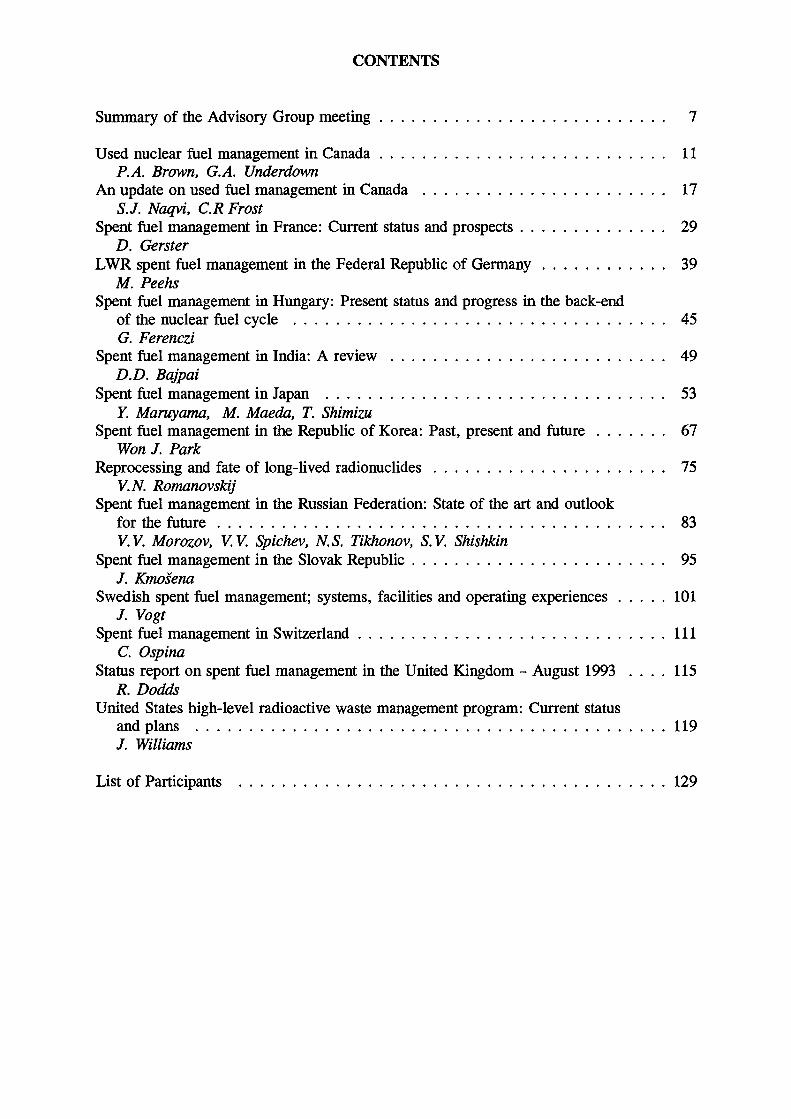
I2020 2030 2040
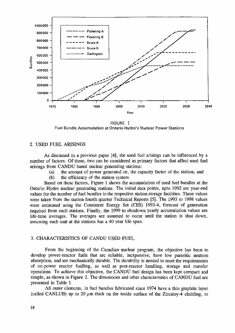
FIGURE 1Fuel Bundle Accumulation at Ontario Hydro's Nuclear Power Stations
2. USED FUEL ARISINGS
As discussed in a previous paper [4], the used fuel arisings can be influenced by anumber of factors. Of these, two can be considered as primary factors that affect used fuelarisings from CANDU based nuclear generating stations:
(a) the amount of power generated or, the capacity factor of the station; and(b) the efficiency of the station system.
Based on these factors, Figure 1 shows the accumulation of used fuel bundles at theOntario Hydro nuclear generating stations. The initial data points, upto 1992 are year-endvalues for the number of fuel bundles in the respective station storage facilities. These valueswere taken from the station fourth quarter Technical Reports [5]. The 1993 to 1998 valueswere estimated using the Consistent Energy Set (CES) 1993-4, forecast of generationrequired from each stations. Finally, the 1999 to shutdown yearly accumulation values arelife-time averages. The averages are assumed to occur until the station is shut down,assuming each unit at the stations has a 40 year life span.
3. CHARACTERISTICS OF CANDU USED FUEL
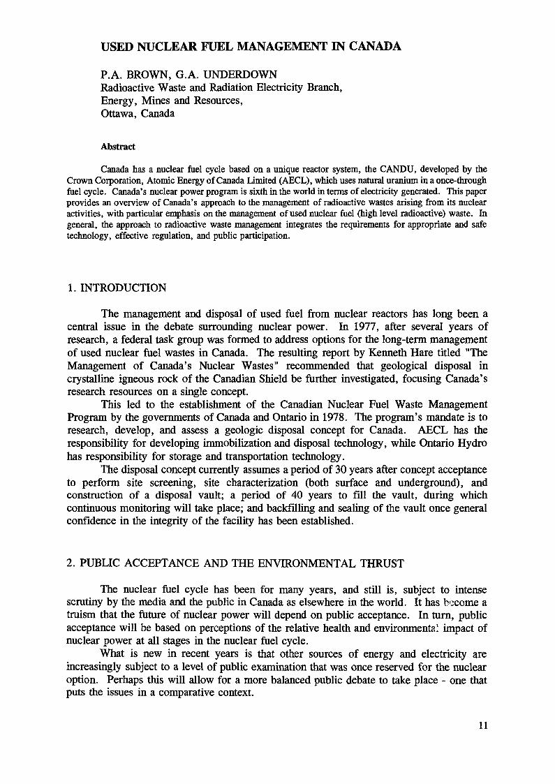
From the beginning of the Canadian nuclear program, the objective has been todevelop power-reactor fuels that are reliable, inexpensive, have low parasitic neutronabsorption, and are mechanically durable. The durability is needed to meet the requirementsof on-power reactor fuelling, as well as post-reactor handling, storage and transferoperations. To achieve this objective, the CANDU fuel design has been kept compact andsimple, as shown in Figure 2. The dimensions and other characteristics of CANDU fuel arepresented in Table 1.
All outer elements, in fuel bundles fabricated since 1974 have a thin graphite layer(called CANLUB) up to 20 /mi thick on the inside surface of the Zircaloy-4 cladding, to
18

1. Ziicaloy Bearing Pad2. Zlrcaloy Fuel Cladding3. Zlrcaloy End Support4. Uranium Oioxido5. Canlub Graphite Intertayor6. Interelomeni Spacer7. Zircatoy End Cap8. Pressure Tuho9. Cnlniuliia Tulio
FIGURE 2Pickering NGS 28 Element Fuel Bundle
TABLE 1Characteristics of Canadian Fuel Bundles
Station
Number ol Elements per Bundle
Pickering A
28
Pickering B
28
Brace A
37
Bruce B
37
Darlington
37
Pt. Lepreau& Gentilly-2
37
ELEMENTS
Material
Outside Diameter (mm)Min. Cladding Thickness (mm)
ZIRC-4
15.19
0.38
ZIRC-4
15.19
0.38
ZIRC-4
13.08
038
2IRC-4
13.08
0.38
ZIRC-4
13.08
0.38
2IRC-4
13.08
0.38
BUNDLES
1 ength (mm)
Maximum Diameter (mm)
Average Discharge Burnup(MW'h/kgU)
095.30
102.49
203
495.30
102.49
193
495.30
102.49
201
495.30
102.49
178
495.3
102.49
180
495.30
102.49
177
reduce susceptibility to fission product-induced stress corrosion and embrittlement of thecladding. Fuel performance limits and in-reactor fuel cladding through-wall defects have hada negligible effect on station safety, reliability, the environment and cost [6]. The actualincapability resulting from fuel defects is less than 0.1 percent over the station's lifetimes [7].
The zirconium alloy-clad natural uranium dioxide CANDU fuel has proven to beideally suited for wet and dry storage. The fuel bundles (Figure 2) are about 50 cm long byabout 10 cm in diameter and weigh about 25 kg each. At an average reactor discharge
19
RckermgGSUsed Fuel Storage Basket
(32 Bundle Capacity. StorageDensity =1608 kg U/m3)
Used Fuel Shippingand Storage Module
(96 Bundle Capacity, StorageDensity-2371 kg U/m3)
BruceGSUsed Fuel Storage Tray
(24 Bundle Capacity. StorageDensity - 2251 kg U/m3)
CANDU 600 MW(e)Used Fuel Storage Tray
(24 Bundle Capacity. StorageDensity = 1972kgU/mJ)
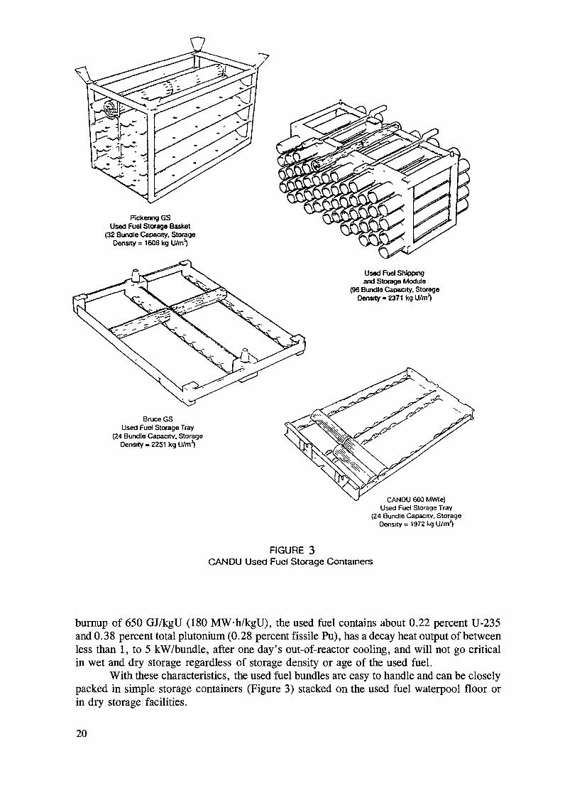
FIGURE 3CANDU Used Fuel Storage Containers
burnup of 650 GJ/kgU (180 MW-h/kgU), the used fuel contains about 0.22 percent U-235and 0.38 percent total plutonium (0.28 percent fissile Pu), has a decay heat output of betweenless than 1, to 5 kW/bündle, after one day's out-of-reactor cooling, and will not go criticalin wet and dry storage regardless of storage density or age of the used fuel.
With these characteristics, the used fuel bundles are easy to handle and can be closelypacked in simple storage containers (Figure 3) stacked on the used fuel waterpool floor orin dry storage facilities.
20

TABLE 2Canadian Used Fuel Waterpools
Station
Pickering A
Pickering B
Briice A
Brucc B
Darlincjton'-'1
Genlilly-2 •
Pt. Lepreau
Type
PrimaryAuxiliaryPrimary
PrimaryAuxiliaryPrimaryAuxiliary
Primnry
Primary
Primary
Dimensions"1 (m)
16.3Wx29.3Lx8.1D17Wx34Lx8.1D
16.3WX 29.31x8.1 D
10Wx41Lx6D18Wx 46Lx9D
10Wx46Lx6D18Wx46Lx9D
(n) D.65W x 20.6L x 50(li) 1/WX32I. X9.2D(c) 17Wx4l.x9.2D
11.SWx22.1Lx7.6D
11.9Wx19.8Lx 7.6D
Capacity OOO'sof Bundles
9321<t158
21352
36330
212
47.4
45.4
In-ServlceDate
19721978
1983
19771979
19831987
1989
1983
1983
Liner Material
All epoxyAll epoxy
Receiving bays, all S/S;Storage bay. all epoxy
S/S-lloor. epoxy wallsS/S-llcor, epoxy walls
All S/SAll S/S
All S/S
All epoxyS/S lloor. epoxy walls
[1) W = Widili. L = Length, 0 - Depth, S/S = Stainless Steel.(2) Darlington will have two identical primary pools, the second one will be In service in 1993. Each primary pool consists of a luel receiving
• ' bay [a), storage bay (b) and a fuel cask handling bay (c). The second primary pool will also have a capacity ol 212.000 bundles.
4. STORAGE FACILITIES
Wet Storage FacilitiesFacility Description:
All Canadian waterpools are located at nuclear generating station sites. Data on thetype, size, liner material, fuel storage capacity and in-service date for the used fuel storagepools are given in Table 2. The on-site pools are of two types; i.e., primary and auxiliary(or secondary).
The primary pools consist of two compartments (Darlington NGS primary pool hasa third compartment, the cask handling bay, separated by a hydraulically operated gate). Thetwo compartments are (a) the receiving bay(s) to which the used fuel is discharged from thereactors for initial storage and cooling and (b) the storage bay, where the used fuel is storeduntil eventual transfer to an auxiliary pool.
The primary pools were designed and constructed along with the other stationfacilities, while the auxiliary pools were later added as complementary storage facilities. Theauxiliary pools, which consist of a single compartment, are very similar to the primary poolsin function and operation. They are designed to receive and store fuel after its initial coolingin primary pools, and provide additional storage capacity as needed. The auxiliary pools alsohave provision for receiving used fuel off-site transportation casks.
The waterpool walls and floor are carbon steel-reinforced concrete about two metresthick. Inner walls and floors are lined with either stainless steel or a fibreglass-reinforcedepoxy compound, or a combination of the two, to form a watertight liner.
Storage containers are used to hold the fuel and permit adequate cooling under allroutine conditions. In all pools, water is circulated through cooling and purification circuits.
Dry StorageCanada is a world leader in the implementation of vertical, reinforced concrete
container-used fuel storage facilities. Concrete canisters (Figure 4) are used to store all usedfuel from the retired CANDU research and prototype reactors WR-1, Gentilly-1, DouglasPoint and NPD, and for >6 year cooled fuel from the operational reactor at Pt. Lepreau(Table 3). Two full-scale prototype dry storage containers have been used for a successful
21
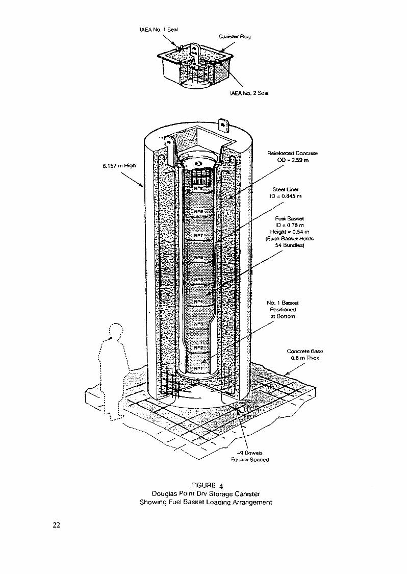
IAEA No. 1 SealCanister Plug
IAEA No. 2 Se ai
6.157 m High
Reinkxced Concrete
Steöün«10 = 0.845 m
Fuel BasketID = 0.78 m
Height = 0.54 m(Each Basket Holds
54Bundl«sl
No. 1 BasketPositionedat Bottom
Concrete Base0.6 m Thick
-*9 DowelsEqually Soaced
FIGURE 4Douglas Point Dry Storage Canister
Showing Fuel Basket Loadinq Arrangement
22
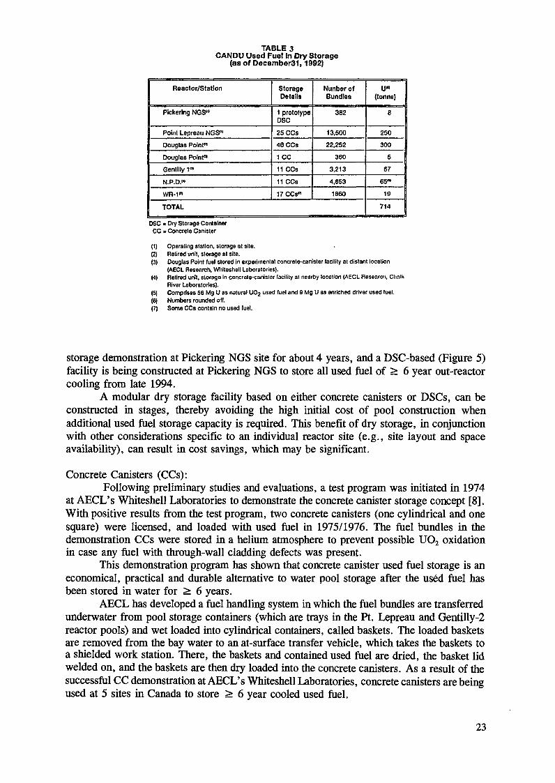
TABLE 3CANDU Used Fuel in Dry Storage
(as of December31,1992)
Reactor/Station
Pickering NGS"
Poinl Lepreau NOS™
Douglas Point«
Douglas Point"
Gentllly 101
N.P.D.«
WR-1"1
StorageDetails
1 prototypeDSC
25CCS46 CCs
1CC
11 CCs
11 CCs
17 CCs"
Nunber ofBundles
382
13.50022.252
360
3,213
4,853
1860
TOTAL
u«(tonne)
8
250
300
5
67
65™
19
714
DSC « Dry Storage ContainerCC = Concrete Canister
(1) Operating station, storage at site.(2) Retired unit, storage at site.(3) Douglas Point fuel stored in experimental concrete-canister facility at distant location
(AECL Research, Whlleshell Laboratories).(4) Retired unit, storage In concrete-canister facility at nearby location (AECL Research, Chalk
River Laboratories).(5| Comprises 56 Mg U as natural U02 used fuel and 9 Mg U as enriched driver used fuel.(6) Numbers rounded off.(7) Some CCs contain no used fuel.
storage demonstration at Pickering NGS site for about 4 years, and a DSC-based (Figure 5)facility is being constructed at Pickering NGS to store all used fuel of > 6 year out-reactorcooling from late 1994.
A modular dry storage facility based on either concrete canisters or DSCs, can beconstructed in stages, thereby avoiding the high initial cost of pool construction whenadditional used fuel storage capacity is required. This benefit of dry storage, in conjunctionwith other considerations specific to an individual reactor site (e.g., site layout and spaceavailability), can result in cost savings, which may be significant.
Concrete Canisters (CCs):Following preliminary studies and evaluations, a test program was initiated in 1974
at AECL's Whiteshell Laboratories to demonstrate the concrete canister storage concept [8].With positive results from the test program, two concrete canisters (one cylindrical and onesquare) were licensed, and loaded with used fuel in 1975/1976. The fuel bundles in thedemonstration CCs were stored in a helium atmosphere to prevent possible UO2 oxidationin case any fuel with through-wall cladding defects was present.
This demonstration program has shown that concrete canister used fuel storage is aneconomical, practical and durable alternative to water pool storage after the used fuel hasbeen stored in water for > 6 years.
AECL has developed a fuel handling system in which the fuel bundles are transferredunderwater from pool storage containers (which are trays in the Pt. Lepreau and Gentilly-2reactor pools) and wet loaded into cylindrical containers, called baskets. The loaded basketsare removed from the bay water to an at-surface transfer vehicle, which takes the baskets toa shielded work station. There, the baskets and contained used fuel are dried, the basket lidwelded on, and the baskets are then dry loaded into the concrete canisters. As a result of thesuccessful CC demonstration at AECL's Whiteshell Laboratories, concrete canisters are beingused at 5 sites in Canada to store > 6 year cooled used fuel.
23

Shield Plate üdLocating
PinVent Port
Lift Plate
Fuel Bundles(Total 384)
Drain Port
Seal/StructuralWeld
Fuel Modules(Total 4)
ReinforcedHigh Density
Concrete
Steel InnerLiner
Sled OuterLiner
FIGURE 5Dry Storage Container for Used Fuel Storage
Dry Storage Containers:Preliminary work in Ontario Hydro's dry storage container (DSC) program focused
on the development of cementitious materials that, with reinforcement, would meet applicableperformance criteria. In subsequent work, the feasibility of integrated concretecontainer-based systems was evaluated by building and testing two half-scale DSCs(assessment prototypes). The tests comprised thermal tests (to simulate storage of <5 yearcooled used fuel), impact, drop and fire tests.
24

These half-scale model tests indicated that the then-current prototype DSC design(without impact limiters) had good potential for meeting AECB transportation licensing tests.Crushing of concrete at the point of impact was as expected, resulting in a reduction of wallthickness, but no unacceptable loss of shielding.
Next, a DSC storage demonstration was initiated at Pickering NGS site, using twofull-scale prototype containers (each of about 400 fuel bundle capacity), loaded with usedfuel. The first prototype DSC was loaded with modules of 10 year cooled fuel; > 6-yearout-reactor cooled fuel was loaded into the second. Operating experience (i.e., loading,draining, drying, decontamination and transfer to the outside storage location) with theprototype DSCs has demonstrated the feasibility of using the DSCs on a production basis.A comprehensive monitoring program has been carried out for more than 4 years to assessthe performance of the prototype DSCs in the storage mode.
5. LONG-TERM INTEGRITY OF CANDU USED FUEL IN WET AND DRY INTERIMSTORAGE
A major requirement for interim fuel storage is that the fuel retains its integrity. Inthis section, the possible mechanisms of used fuel degradation in wet and dry storage arediscussed, and based on these possible modes of degradation, the long-term fuel integrity instorage is evaluated. As the storage medium and temperature have an effect on the possibledegradation modes, wet and dry storage are considered separately.
The possible modes of fuel degradation in wet and dry storage are:(1) cladding oxidation and UO2 oxidation (for the < 0.1 % of used fuel bundles
with a through-wall cladding defect);(2) UO2 dissolution (for defected fuel in wet storage);(3) fission product-induced stress; corrosion/ embrittlement of the cladding;(4) delayed hydride cracking of the cladding.
Wet Storage
Cladding Oxidation:Two re-examinations of used CANDU fuel elements (which were characterised after
discharge from the reactor) in the wet storage fuel integrity program have been carried outafter up to 17 years and up to 27 years wet storage respectively. In the first re-examinationin 1978, there was no measurable oxidation of the cladding outer surface [9]. In the secondre-examination in 1988, no apparent change had occurred in the condition and thickness ofthe zirconium oxide layer on the cladding outer surface, since the previous examination, forall elements, including those in wet storage for the longest period (=27 years) [10]. For anintentionally defected element stored for about 21 years underwater, there was no evidenceof zirconium oxide buildup on the surface of the hole drilled in the cladding and, for theinner cladding surface, no significant changes were detected.
It was concluded that oxidation will not result in cladding failure for 100 years wetstorage, or even longer, for both intact used fuel and used fuel with a through-wall claddingdefect.
UO2 Oxidation/Dissolution:For used fuel with a through-wall cladding defect, the UO2 fuel matrix would be
exposed to the water storage medium. The significance of UO2 oxidation relative to fuelintegrity is that the UO2 could eventually form oxidation products (i.e., U3O8 and/or UO3
25

hydrates) which are less dense than the parent UO2. Thus, UO2 oxidation may eventuallycause cladding splitting at the through-wall defect from UO2 matrix expansion.
In the 1988 re-examination, it was observed that some change in the UO2 matrix hadoccurred in a defected element wet stored for 21 years. The surface of the UO2 where it wassampled was oxidized and fully hydrated. The U6+/U4+ ratio determined by X-rayphoto-electron spectroscopy (XPS) indicated an average value of 71 percent UO3 on thesurface of UO2 fragments obtained at positions from ~ 10 mm to 265 mm from the defect.X-ray diffraction of UO2 particles taken from 5 to 15 mm from the defect showed noapparent evidence of UO2 oxidation. This suggests that if UO2 oxidation had occurred, theoxidation product was likely present on the UO2 surface to a depth of less than 2 /un, as XPSis very surface-sensitive. No evidence of diametral increase in this element due to UO2swelling was observed after 21 years wet storage. Crystal growth was observed by scanningelectron microscopy (SEM) on the surface of UO2 fragments taken from =10 to 135 mmfrom the cladding defect after 21 years wet storage. The crystals showed the presence ofuranium atoms. This crystal growth indicates some uranium dissolution and redeposition,probably as UO3 hydrates [10]. There was an insignificant volume increase caused by theobserved uranium dioxide oxidation and subsequent dissolution/redeposition.
Cladding Fission Product-induced Stress
Corrosion/Embrittlement Cracking:Tensile tests on cladding ring samples from 14 bundles stored under water for 13 to
21 years indicated no significant change in mechanical properties between the first andsecond re-examinations. In addition, no incipient cracking was observed on the cladding innersurface. These results indicate that no fission product stress corrosion cracking/embrittlementcracking had occurred in up to 21 years wet storage.
Cladding Delayed Hydride Cracking:There was no significant difference observed in hydrogen isotope analysis of the
cladding in the pre-storage, and first and second interim storage examinations. Similarly, nomigration of cladding hydrogen isotopes had occurred in fuel stored for up to 27 years. Asthere was also no change in the cladding mechanical properties over this storage period, itis concluded that no delayed hydride incipient cracking has occurred after 27 years wetstorage.
Dry Storage
A recent paper [11] has reviewed, in detail, the possible CANDU used fueldegradation mechanisms for Ontario Hydro's used fuel in DSC dry storage. Although theselected DSC cover gas is helium, the assessment was carried out for air, helium with someair in-leakage, and helium. The maximum predicted DSC cover gas temperature is 137°C,which could only be attained in the first year of storage with 6 year out-reactor cooled fuel.
It was concluded that, based on present data, no loss of used fuel integrity by any ofthe possible degradation mechanisms (i.e., cladding oxidation, cladding fissionproduct-induced stress corrosion/embrittlement, cladding delayed hydride cracking, and UO2oxidation), should occur for the expected range of operating conditions in the Pickering NGSdry storage containers with a helium or air cover gas, for extended storage periods of up to100 years, or more. This conclusion would also apply to AECL-designed concrete canisters.
26
6. SAFETY OF INTERIM STORAGE OF USED FUELAlthough the CANDU used fuel that is in interim wet and dry storage contains a
significant inventory of radioactive material, there have never been any questions about itssafe storage. In common with the interim storage experience in other countries, there havebeen minor operating problems with used fuel wet storage facilities, but there have been noevents of real significance, relative to safety, associated with any of the Canadian fuel storagepools. None of the pool operating problems have had any public dose impact over a totaloperational period of > 45 years.
There have also been no incidents [12] with the dry storage of used fuel at Canadianutility locations (Pickering, Gentilly-1 and Pt. Lepreau NGSs), nor at the AECL sites atDouglas Point, Whiteshell Laboratories, and Chalk River Laboratories, demonstrating theinherent safety of Canadian dry storage facilities.
7. CONCLUSIONS
Canadian interim wet storage (over a period of more than 45 years) and dry storage(over a period of about 16 years) facilities have been used to manage successfully and safelyCANDU used fuel discharged from 22 power reactors (and other research and prototypereactors).
Results from the first CANDU used fuel re-examination after <17 years wet storageand the second re-examination after <_ 27 years wet storage indicate that Ontario Hydro'sused fuel, whether intact or defected, can be stored hi water for at least 50 years with nosignificant degradation, provided the UO2 oxidation rate does not increase significantly. Ifthe used fuel has intact cladding, no loss of fuel integrity is expected to occur for more than100 years. Similar long-term durability would be expected for wet stored CANDU fuel atPt. Lepreau and Gentilly-2.
REFERENCES
[1] OECD/NEA Brochure Series: "Radioactive Waste Management in Canada," 1992.[2] ONTARIO HYDRO, "Radioactive Materials Management at Ontario Hydro: The Plan
for Used Fuel," 1991.[3] DORMUTH, K.W. and K. NUTTAL: "The Canadian Nuclear Fuel Waste Program,
"Radioactive Waste Management and Nuclear Fuel Cycle, Vol. 8(2-3), pp. 92-104,1987.
[4] NAQVI, S. J., "Spent Fuel Management in Canada: Current Developments and FuturePlans, " paper presented at the IAEA Regular Advisory Committee Meeting on SpentFuel Management, March 19-22, 1990, Vienna, Austria.
[5] ONTARIO HYDRO Nuclear Power Generating Stations Quarterly Technical Reports,1992.
[6] TRUANT, P.T., and HASTINGS, I.J., "CANDU Reactor Experience: FuelPerformance," Atomic Energy of Canada Limited Report No. AECL-8774(July 1985).
[7] LEE, R.T., "Fuel Performance in Ontario Hydro Nuclear Generating Stations."Paper presented at the 21st Intl. Utility Fuel Performance Conference, Minneapolis,Min, USA (Sept 24 to 27, 1990).
27

[8] SOCHASKI, R.O., "Canadian Experience with Concrete-Canister Dry Fuel Storage. "Paper presented at Ontario Hydro International Work shop on Irradiated Fuel StorageOperating Experience and Development Programs, Toronto, Ontario (October 17-18,1984).
[9] HUNT, C.E.L., WOOD, J.C., SURETTE, B.A. and FREIRE-CANOSA, J. 1981."Seventeen Years of Experience with Storage of Irradiated CANDU Fuel UnderWater." Paper presented at NACE Corrosion 81 Conference, Toronto, Canada(April 1981).
[10] WASYWICH, K.M. and FROST, C.R., "Examination of Used CANDU FuelFollowing 27 Years of Storage under water. " Paper presented at 3rd Intl. Conferenceon Nuclear Fuel Reprocessing and Waste Management (RECOD 91) Sendai, Japan(April 14-18, 1991).
[11] FROST, C.R., "Used CANDU Fuel Component Integrity in Dry Storage -Experimental Programs. " Paper presented at the 3rd International Conference onCANDU Fuel, Chalk River, Ontario (October 6-8, 1992).
[12] WASYWICH, K.M., "Spent Fuel Dry Storage Experience in Canada." Paperpresented at IAEA Behaviour of Spent Fuel Assemblies and Storage FacilityComponents during Long-Term Storage (BEFAST-Ill) Meeting, Toronto, Ontario(October 19-23, 1992).
28

SPENT FUEL MANAGEMENT IN FRANCE:CURRENT STATUS AND PROSPECTS
D. GERSTERDirection du cycle du combustible,Commissariat à l'énergie atomique,Centre d'études de Saclay,Gif-sur-Yvette, France
Abstract
In 1992, the French nuclear power plants supply approximately 320 TWh, and 1100 metric tons ofspent fuels were discharged. In 2000, for the same amount of unloaded fuel, the power supply is estimated tobe about 485 TWh. Since the beginning of its electronuclear program, France has opted for spent fuel reprocess-ing, the only strategy leading to save energy resources by the recycling of energetic materials, coupled withselective and progressive treatment and disposal of ultimate waste, in order to preserve at best the environment.The technologies for reprocessing and waste treatment, developed hi line with the other fuel cycle steps, likeMOX fuel fabrication, have become now a complete mature industry with the operation of the UP-3 reprocess-ing plant (capacity : 800 tHM/y), the commissioning of UP2-800 (capacity : 800 tHM/y) and the constructionof the Melox plant (capacity : up to 160 tHM/y). The recycling of plutonium in PWRs is industrially appliedsince 1987. Today, five of the sixteen reactors approved for MOX fuel operation are loaded with that fuel.Twelve other could use MOX fuel with no technical modifications. To the end of 1992, 140 tons of MOX fuelhad been loaded hi the EOF PWRs. Promising R&D programs are currently carried out especially in twodirections : recycling and waste management. The first one is devoted to increase the plutonium consumptionin PWRs and hi fast reactors. The second one, called SPIN, is aimed at waste minimization (volumes and long-lived activities) hi order to reduce the toxicity of ultimate waste disposal.
1. INTRODUCTION
In 1992, the French nuclear power plants supply 320 TWh, that is about 75% of thenational electricity output (+1,6%), corresponding to 75,1 million tons of oil equivalent(Fig. 1).
Long term use of nuclear energy implies recycling. Thus, since the beginning of itselectronuclear program, France has opted for spent fuel reprocessing, the only strategy lead-ing to save energy resources by the recycling of energetic materials, uranium and plutonium,coupled with selective and progressive treatment and disposal of ultimate waste, in order topreserve at best the environment.
The processes and technologies for reprocessing and waste treatment, developed inline with the other fuel cycle steps, like MOX fuel fabrication, have become now a completemature industry with the operation of the UP-3 reprocessing plant, the commissioning ofUP2-800 and the construction of the Melox plant.
2. SPENT FUEL ARISINGS
In 1992, one 1,300 MWe PWR unit has been connected to the grid (Penly-2) and oneGCR has been definitively shut down (Saint Laurent A-2). At the end of 1992, the installednuclear power capacity totalled up to 57,718 MWe with 56 units : 52 PWRs, 1 GCR and 2FBR. In may!993, France's 57th reactor (Golfech-2) started up : it is the 20th operating PWR-1300. To date, 4 other reactors are under construction and 4 under project.
29

TOTAL TWhNUCLEAR TWh% NUCLEAR
1990
399.5297.774.5
1995
440332.575.5
2000
485.2364.775.2
2005
502.038676.8
2010
520.440477.7
Fig. 1 : Estimates of total and nuclear electricity generationin France.
uoxMOX-
TOTAL
1992
1.065
35
1.100
1995
1.035
65
1.100
2000
1.010/980
90/120
1.100
2005
1,110/1,080
90/120
1.200
2010
1,160/1130
90/120
1,200
• calculated with the current EOF/MOX program ot 5 reactors until 199S, 8 to 14 reactors from1996 to 1999,16 reactors from year 2000.
Fig. 2 : Annual spent fuel discharges In metric tons of heavy metal.
The present core management strategy involves for the 900 M We units, an annualreloading scheme of 1/4 core and discharge burn-up of 39-45,000 MWd/ton, instead of a 1/3core and burn-up of 33,000 MWd/ton. At the end of 1992, 25 of the 34 units applied thisstrategy.
In the future, higher burn-ups in the range 50-60,000 MWd/ton either with longcampaign, or with annual reloadings 1/5 core could be attained, leading to decrease thequantities of unloaded fuels.
In 1992, 1,100 tHM were discharged from the french PWR power plants (916 tonsin 1991) (Fig. 2).
3. SPENT FUEL TRANSPORTATION
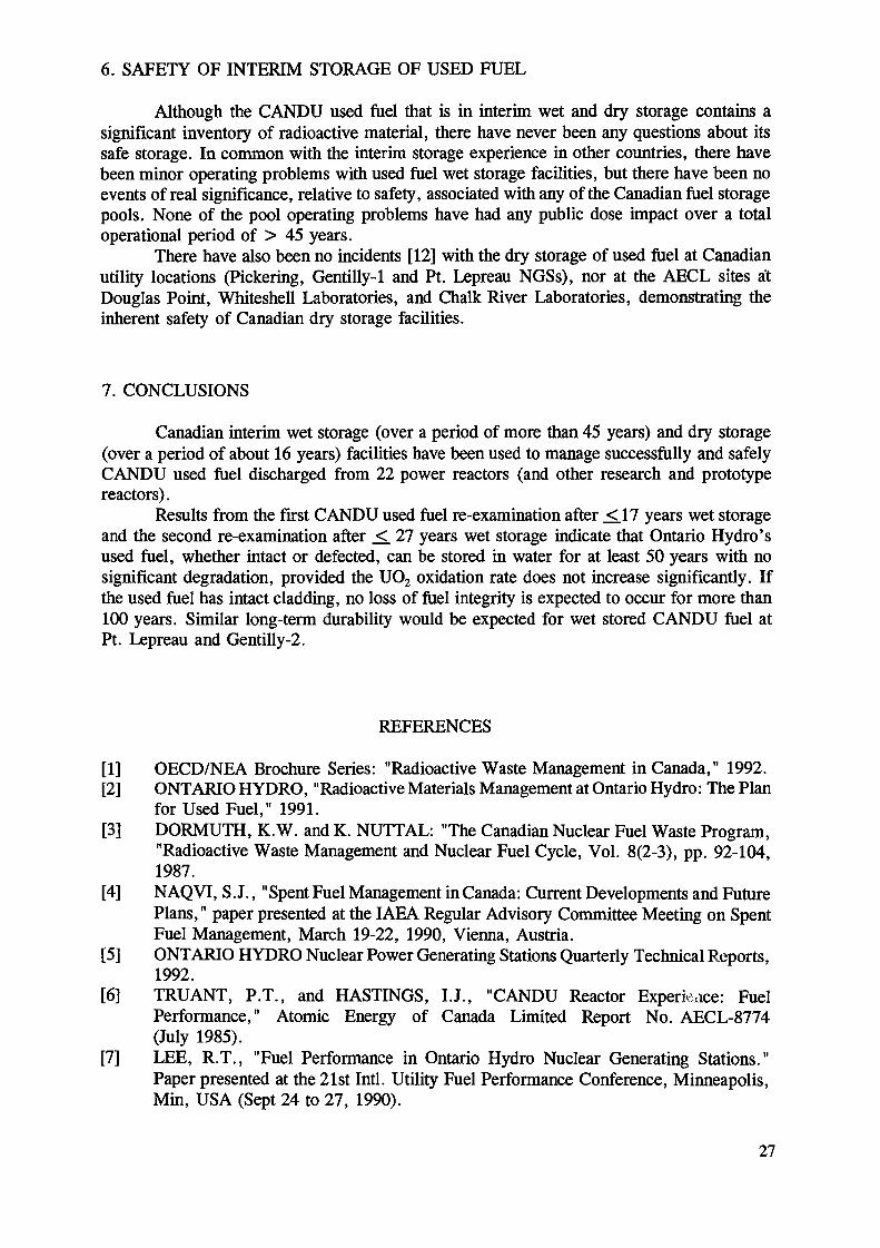
A specialized organization is used by Cogema for managing all nuclear materialstransports, and relies upon most competent international companies : Transnucléaire, NuclearTransport Limited and Pacific Nuclear Transport Limited.
A considerable industrial experience has now been acquired in spent fuel handling andtransport (Fig. 3). Over 3800 transport casks shipments from 71 French and foreign reactorshave been carried out so far, and over 13,966 tons HM of fuel has been delivered as of June1993. For OCR fuels, 10,415 tons HM of spent fuel has been transported as of June 1993.
4. SPENT FUEL STORAGE
The La Hague storage facilities are capable of holding upwards of 14,400 tHM ofspent fuel. A dry storage facility, Cascad, is in operation at Cadarache, used for the storageof HWR (EL-4) and research reactor irradiated fuel. Its capacity is 200 tHM. Cascad is about25% full today. The French spent fuel storage capacity could be increased by the end of thecentury : various options are being studied.
30
OCR
LWR
FBR
SITE
La Hague 1966/1 987
Marcoule 1975/1993
La Hague 1973/1 993
La Hague 1968/1 984
QUANTITYTons HM
4895
5520
13.966
10.6
NUMBER OFCASKS
1600
1430
3800
125
Fig. 3 : Spent fuel transport experience
UP2UP3
1993
300600
1994
650700
1995
850800
1996
850900
1997
850900
1998
850900
1999
850800
2000
850800
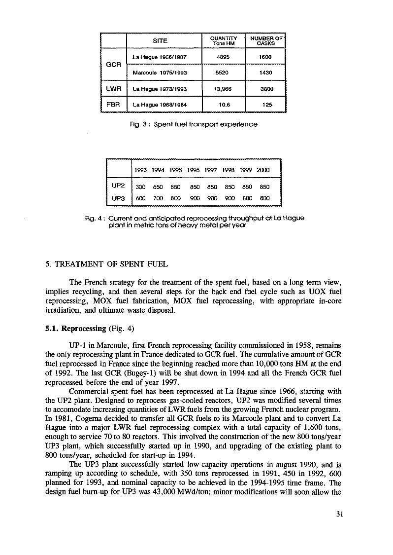
Fig. 4 : Current and anticipated reprocessing throughput at La Hagueplant in metric tons of heavy metal per year
5. TREATMENT OF SPENT FUEL
The French strategy for the treatment of the spent fuel, based on a long term view,implies recycling, and then several steps for the back end fuel cycle such as UOX fuelreprocessing, MOX fuel fabrication, MOX fuel reprocessing, with appropriate in-coreirradiation, and ultimate waste disposal.
5.1. Reprocessing (Fig. 4)
UP-1 in Marcoule, first French reprocessing facility commissioned in 1958, remainsthe only reprocessing plant in France dedicated to OCR fuel. The cumulative amount of OCRfuel reprocessed in France since the beginning reached more than 10,000 tons HM at the endof 1992. The last OCR (Bugey-1) will be shut down in 1994 and all the French OCR fuelreprocessed before the end of year 1997.
Commercial spent fuel has been reprocessed at La Hague since 1966, starting withthe UP2 plant. Designed to reprocess gas-cooled reactors, UP2 was modified several tunesto accomodate increasing quantities of LWR fuels from the growing French nuclear program.In 1981, Cogema decided to transfer all OCR fuels to its Marcoule plant and to convert LaHague into a major LWR fuel reprocessing complex with a total capacity of 1,600 tons,enough to service 70 to 80 reactors. This involved the construction of the new 800 tons/yearUP3 plant, which successfully started up in 1990, and upgrading of the existing plant to800 tons/year, scheduled for start-up in 1994.
The UP3 plant successfully started low-capacity operations in august 1990, and isramping up according to schedule, with 350 tons reprocessed in 1991, 450 in 1992, 600planned for 1993, and nominal capacity to be achieved in the 1994-1995 time frame. Thedesign fuel burn-up for UP3 was 43,000 MWd/ton; minor modifications will soon allow the
31
TYPE OFPRODUCTS
FISSION PRODUCTS
HULLS & END-FITTINGS
BITUMEN WASTE
TECHNOLOGICAL RESIDUE
TOTAL
SURFACETECHNOLOGICAL RESIDUE
SOLIDIFICATIONMETHOD
GLASS MATRIX
CONCRETE
BITUMEN
GROUTED ASBESTOSCONCRETE OVERPACK
GROUTED FIBERCONCRETE OVERPACK
SPECIFICATIONSUP3, UP2-800
0.13
0.60
0.63
1.7
3.
3.80
ACTUALVALUES
0.115
0.60
0.45
0.20
1.365
1.4
EXPECTED1995
0.115
<0.60
0
0.20
< 0.915
1.4
EXPECTED2000
0.115
0.15
0
<0.20
< 0.465
< 1.4
Fig. 5 : Volumes of residues generated in UP3 in cubic meter/metric tons of reprocessed HM
plant to reprocess fuels with burn-up in excess of 50,000 MWd/ton. MOX fuel can also bereprocessed, as demonstrated for the first time in november 1992, by an industrial campaign.This event marks the final step in complete closure of the fuel cycle.
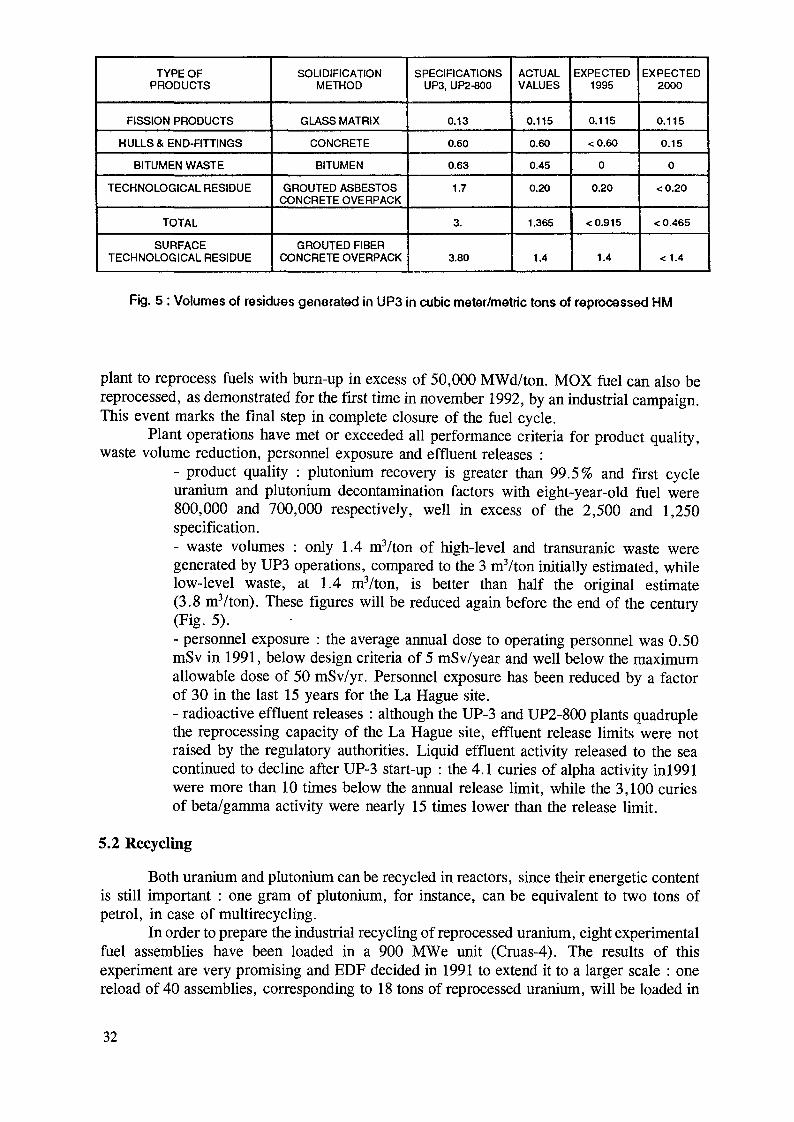
Plant operations have met or exceeded all performance criteria for product quality,waste volume reduction, personnel exposure and effluent releases :
- product quality : plutonium recovery is greater than 99.5% and first cycleuranium and plutonium decontamination factors with eight-year-old fuel were800,000 and 700,000 respectively, well in excess of the 2,500 and 1,250specification.- waste volumes : only 1.4 nrVton of high-level and transuranic waste weregenerated by UP3 operations, compared to the 3 nvYton initially estimated, whilelow-level waste, at 1.4 mVton, is better than half the original estimate(3.8 m3/ton). These figures will be reduced again before the end of the century(Fig. 5).- personnel exposure : the average annual dose to operating personnel was 0.50mSv in 1991, below design criteria of 5 mSv/year and well below the maximumallowable dose of 50 mSv/yr. Personnel exposure has been reduced by a factorof 30 in the last 15 years for the La Hague site.- radioactive effluent releases : although the UP-3 and UP2-800 plants quadruplethe reprocessing capacity of the La Hague site, effluent release limits were notraised by the regulatory authorities. Liquid effluent activity released to the seacontinued to decline after UP-3 start-up : the 4.1 curies of alpha activity in!991were more than 10 times below the annual release limit, while the 3,100 curiesof beta/gamma activity were nearly 15 times lower than the release limit.
5.2 Recycling
Both uranium and plutonium can be recycled in reactors, since their energetic contentis still important : one gram of plutonium, for instance, can be equivalent to two tons ofpetrol, in case of multirecycling.
In order to prepare the industrial recycling of reprocessed uranium, eight experimentalfuel assemblies have been loaded in a 900 MWe unit (Cruas-4). The results of thisexperiment are very promising and EDF decided in 1991 to extend it to a larger scale : onereload of 40 assemblies, corresponding to 18 tons of reprocessed uranium, will be loaded in
32

1993 (at least two in 1994) with quarter core management (47,000 MWd/t). By the end ofthe century, 90 extra tons of reprocessed uranium would have been recycled.
For the fuel fabrication, more than 2000 tons of reprocessed uranium have beenconverted to date from uranyl nitrate into UF6 in a dedicated facility started up in 1976 andwhose capacity is 350 tons/y . A new facility, with a 2 000 tons/y capacity, is underconstruction. It must be in operation in mid-94.
Uranium re-enrichment is presently contracted to Tenex or Urenco facilities,considering that ultracentrifugation is a process more convenient than gaseous diffusion usedtoday at Eurodif (waiting for SILVA, the future laser process currently under developmentin France).
The FBFC fuel fabrication plant (located in Romans) is now equipped with a newproduction line, with a capacity of 200 tons, devoted to re-enriched uranium.
Plutonium recycling as a mixed oxide fuel has been carried out in France for a longtime, initially for the FBRs Phénix and Superphenix. At Cadarache, from 1964 to the endof 1992, the CFCa facility produced 120 tons of plutonium-containing fuel : 103 tons of fastreactor fuel and 11 tons of MOX fuel for PWRs. Its capacity was 9 tons in 1992, with anobjective of 15 tons in 1993 and 35 tons by the year 2,000 (MOX fuel for PWRs).
The Melox plant, devoted to MOX fuel manufacturing, will be in operation in 1995,with an expected production of 50 tons for the first year. After reaching its full capacity of100 tons per year the following year, the Melox yearly capacity will increase gradually hiorder to reach about 160 tons around the year 2,000.
Presently, the fabrication of French MOX is carried out in the Belgonucléaire's Desselplant and at the CFCa facility (Fig. 6).
CFCAMELOXPOP1
1993
150350
1994
15035O
1995
2050350
1996
25100400
1997
3O120400
1998
351304010
1999
351504030
2000
3516O4040
Fig. 6 : Current and anticipated MOX fabrication capacityIn metric tons of heavy metal per year
In 1983, EDF decided to recycle plutonium in its PWRs. Plutonium recycling isapplied since november 1987 at a rate of 30% MOX fuel assemblies in the core of 900 MWereactors in EDF plants. Today, five of the sixteen units that have been approved for MOXfuel operation are loaded with that fuel : St Laurent B-1 and B-2, Gravelines B-3 et B-4 etDampierre-1. In four of them, the proportion of MOX has reached the authorized equilibriumvalue. These five reactors are operated in base-load with a third of the core reloadedannually, and two of them are authorized for load-follow operation for demonstrationpurposes. The maximum authorized value of average fuel assembly burn-up, 36,000MWd/ton, has been effectively achieved in three units without problems. The currentdevelopments will lead to an average burn-up of 45,000 MWd/ton. Twelve other PWRscould use MOX fuel with no technical modifications. Moreover, the future N4 (1,450 MWePWR) is yet designed to accept a 30% MOX core.
To the end of 1992, 140 tons of MOX fuel had been loaded in the EDF PWRs.
33

6. WASTE MANAGEMENT
The French waste management policy is to minimize waste volumes and activities,to condition the waste in a solid form suitable for ultimate disposal, and finally to disposeof it in an optimized repository.
6.1 Waste conditioning
In line with reprocessing, vitrification offers a stable and safe solution, long-sincemastered, to package high activity wastes. The R7 and the T7 facilities are under operationat La Hague : they had produced 2,000 canisters at the end of June 1993, corresponding tothe reprocessing of 6,325 tons of LWRs fuel. With 2,000 vitrified blocks now stored,vitrification and dry interim storage of glass are confirmed as totally satisfactory operationsin the industrial application phase in France.
Hulls and end pieces are embedded in concrete : 211 drums have been produced in1992. Sludges produced by the treatment of low and medium activity liquids are incorporatedinto bitumen. The STE3 facility (liquid effluent treatment station) from its June 1989commissioning to the end of 1992, has produced 6,652 drums of bituminized wastes (2986in 1991 and 1,459 in 1992), corresponding to 90,000 m3 of effluents.
6.2 Waste disposal
The long-term industrial management of radioactive waste produced in France is theresponsibility of ANDRA (Agence Nationale pour la gestion des déchets radioactifs). Sincedecember 1992, the Agency is a completely indépendant entity, with close contractualrelationships with the CEA in the field of R&D.
According to the French regulations, the nuclear wastes are divided into 3 categories:-type A with low or medium activity and short half-life,-type B with low or medium activiy and long half-life,-type C with high activity and short or long half-life.
Type A wastes can be surface-disposed of. There are two surface repositories inFrance: the Centre de Stockage de la Manche near La Hague, in operation since 1969 andsoon to be saturated, and the Centre de Stockage de l'Aube at Soulaines, opened in January1992, with an available capacity of 1,000,000 m3 which, at a rate of waste production of30,000 mVyear, which will meet the demand up to year 2020.
Type B wastes must be disposed of in an underground geological site. Planned at arate < 4 000 m3/year, they are presently stored at La Hague, pending a terminal site.
The amount of French type C wastes are expected to be small, about 125 m3/year(figure corresponding to 1,100 tons of reprocessed fuel) . After a storage of several decadeswhich attenuates their heat load, they are to be disposed of in deep underground geologicalsites.
Due to strong opposition at possible sites, the French Government decided in february1990 to adjourn on field investigations. In order to respond to the public concern about thewastes and in particular the long-lived high level ones, two commissions were designated tomake a peer review of basic options concerning the management of the back-end of the fuelcycle. Two reports were published and a law was debated and finally voted in december1991, covering a 15-year program for HLW disposal. By then, the choice of a finalrepository will have to be submitted to a new parliamentary vote. In 1992, a negociator hasbeen designated, in order to facilitate the construction of two underground laboratories.
34
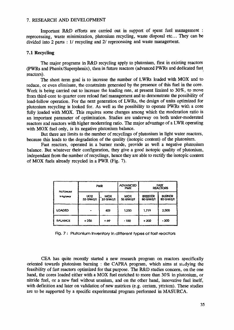
7. RESEARCH AND DEVELOPMENT
Important R&D efforts are carried out in support of spent fuel management :reprocessing, waste minimization, plutonium recycling, waste disposal etc... They can bedivided into 2 parts : I/ recycling and 21 reprocessing and waste management.
7.1 Recycling
The major programs in R&D recycling apply to plutonium, first hi existing reactors(PWRs and Phenix/Superphenix), then in future reactors (advanced PWRs and dedicated fastreactors).
The short term goal is to increase the number of LWRs loaded with MOX and toreduce, or even eliminate, the constraints generated by the presence of this fuel in the core.Work is being carried out to increase the loading rate, at present limited to 30%, to movefrom third-core to quarter core reload fuel management and to demonstrate the possibility ofload-follow operation. For the next generation of LWRs, the design of units optimized forplutonium recycling is looked for. As well as the possibility to operate PWRs with a corefully loaded with MOX. This requires some changes among which the moderation ratio isan important parameter of optimization. Studies are underway on both under-moderatedreactors and reactors with higher moderating ratio. The major advantage of a LWR operatingwith MOX fuel only, is its negative plutonium balance.
But there are limits to the number of recyclings of plutonium in light water reactors,because this leads to the degradation of the quality (isotopic content) of the plutonium.
Fast reactors, operated in a burner mode, provide as well a negative plutoniumbalance. But whatever their configuration, they give a good isotopic quality of plutonium,indépendant from the number of recyclings, hence they are able to rectify the isotopic contentof MOX fuels already recycled in a PWR (Fig. 7).
PUTTONUM
hkg/vwor
LOADED
BALANCE
PWR
UO233<3Wd/t
-
+ 256
_ MOX33GWd/t
409
+ 69
ADVANCEDPWR
MOX56 GWd/t
1250
-150
FASTREACTORS
BREEDER80<3Wd/t
1.719
+ 200
BURNER80GWd/t
2.500
-300
Fig. 7 : Plutonium inventory In different types of fast reactors
CEA has quite recently started a new research program on reactors specificallyoriented towards plutonium burning : the CAPRA program, which aims at studying thefeasibility of fast reactors optimized for that purpose. The R&D studies concern, on the onehand, the cores loaded either with a MOX fuel enriched to more than 30% in plutonium, ornitride fuel, or a new fuel without uranium, and on the other hand, innovative fuel itself,with definition and later on validation of new matrices (e.g. cerium, yttrium). These studiesare to be supported by a specific experimental program performed in MASURCA.
35
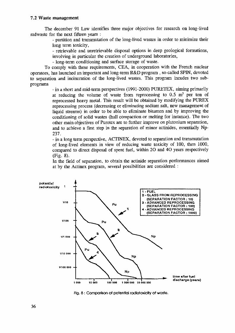
7.2 Waste management
The december 91 Law identifies three major objectives for research on long-livedradwaste for the next fifteen years :
- partition and transmutation of the long-lived wastes in order to minimize theirlong term toxicity,- retrievable and unretrievable disposal options in deep geological formations,involving in particular the creation of underground laboratories,- long-term conditioning and surface storage of waste.
To comply with these requirements, CEA, in cooperation with the French nuclearoperators, has launched an important and long-term R&D program , so-called SPIN, devotedto separation and incineration of the long-lived wastes. This program incudes two sub-programs
- in a short and mid-term perspectives (1991-2000) PURETEX, aiming primarilyat reducing the volume of waste from reprocessing to 0.5 m3 per ton ofreprocessed heavy metal. This result will be obtained by modifying the PUREXreprocessing process (decreasing or eliminating sodium salt, new management ofliquid streams) in order to be able to eliminate bitumen and by improving theconditioning of solid wastes (hull compaction or melting for instance). The twoother main objectives of Puretex are to further improve on plutonium separation,and to achieve a first step in the separation of minor actinides, essentially Np-237.- in a long term perspective, ACTINEX, devoted to separation and transmutationof long-lived elements in view of reducing waste toxicity of 100, then 1000,compared to direct disposal of spent fuel, within 2O and 4O years respectively(Fig. 8).In the field of separation, to obtain the actinide separation performances aimedat by the Actinex program, several possibilities are considered :
potentialradiotoxlcity 1
1/10
1/100
1/1 ooo - -
1/10 000 - •
1/100000 - •
1-FUEL2 - GLASS FROM REPROCESSING
(SEPARATION FACTOR : 10)3 - ADVANCED REPROCESSING
(SEPARATION FACTOR : 100)4 - ADVANCED REPROCESSING
(SEPARATION FACTOR : 10OO)
Np
1 000 10 000 100000 1 OOO 000 10000000
time after fueldischarge (years)
Fig. 8 : Comparison of potential radiotoxicity of waste.
36
- simultaneous extraction of actinides and lanthanides in their stable axidationstate ( valence III for Am, Cm and lanthanides) with a subsequent separation ofthe two series;- selective extraction of actinides in their stable oxidation state in nitric solutionusing very specific and highly efficient products;- selective extraction of actinides in a valence higher than III after oxidizing (IVor VI).
Current studies are oriented towards two types of extractants : diamides (includingpicolinamides) and macrocycles ( crown-ethers, calixarenes). Tests on active real solutionsmay be performed in 1994.
The AT ALANTE facility, located in Marcoule, is significantly dedicated to suchR&D programs in the field of highly radioactive chemistry. These new laboratories receivedtheir first authorization for radioactive operations hi december 1992.
Once chemically separated, the long-lived elements (minor actinides and fissionproducts) may either be mixed with fuel (homogenous concept),or manufactured into targetelements (heterogenous concept), for transmutation.
In the field of transmutation, studies are in progress in 2 directions :- validation of the nuclear data which are necessary for incineration studies (crosssections, yields, decay data),- parametric studies in view of evaluating the feasibility and the conditions ofactinide incineration (reactor type -PWR or fast reactor-, fuel matrices - UO2,MOX, metallic fuel etc...).
An experiment called Superfact has been run in the PHENIX experimental fastreactor, with the homogenous concept involving elements containing Am and Np at low (2%)and high (40-45%) concentrations. This experiment concretely demonstrated the feasibilityof the fabrication, design and irradiation up to about 6% of such fuels and then: goodbehavior with respect to standard pins. Moreover, a panel of experts, consulted last year bythe French Ministry of research, confirmed the interest of Superphenix for largerexperiments.
New studies are directed towards high transmutation efficiencies, i.e. high burn-ups(Superfact II). The same validation is being prepared for the PWRs with the ACTINEAUexperiment in the Osiris research reactor. In parallel, the possibilities of advanced systemssuch as specific nuclear reactors (EFR type loaded with Pu/Am/Np/Cm oxide fuel) oraccelerators (including hybrid systems like proton accelerator associated with subcriticalmedium) are studied.
The themes of the other articles of the december 91 Law, related to the preparationof future repositories, have been studied for many years in France hi terms of engineeredbarriers, geological and geochemical behavior, long term behavior of waste packages etc...
These R&D activities, in support to ANDRA, deal in particular with the long termbehavior of concretes, bitumens and glass under irradiation and water leaching, hi order toknow the source term evolution (radionuclide emission). Predictions derived from modelswill have to be confirmed in representative conditions, i.e. by mean of undergroundlaboratories, two of which should be identified within two years and commissioned wellbefore the year 2000.
7. CONCLUSION
France, facing its scarcity of domestic energy resources, has conducted its energypolicy for more than 20 years with two major guidelines :
- improving its energetic indépendance taking into account its lack of fossileressources,-preserving at the best the environment.
37
The approach chosen to fulfill the first goal has been to resort to nuclear energy bylaunching an important nuclear reactor program, which allowed France to increase itsenergetic indépendance from 27% in 1980 to 49% in 1992, and by closing the nuclear fuelcycle, which permits to recover the fissile materials for further use and dispose of theultimate waste in a suitable way.
But despite the present technical and industrial success of nuclear energy in Franceand despite its economic efficiency, the possibility of heading for further development ispending upon the ability to convince public opinion that nuclear energy is safe both in a shortand in a long term perspective. The French strategy of spent fuel management, includingrecycling and reprocessing, offers a wide range of schedule options and a high degree offlexibility for the different steps of the fuel cycle operations. Moreover, it offers largecapabilities of progress in the field of reducing the potential and residual toxicity of wastedisposal. Both elements capable of helping to set the public mind at rest.
38

LWR SPENT FUEL MANAGEMENTIN THE FEDERAL REPUBLIC OF GERMANY
M. PEEKSSiemens Aktiengesellschaft,Bereich Energieerzeugung KWU,Erlangen, Germany
Abstract
The spent fuel management strategy in the Federal Republic of Germany is based on interim storageand subsequent reprocessing of spent fuel. The waste will be disposed of in a geological repository. Additionalalternative back-end fuel cycle techniques such as the direct disposal of spent fuel without reprocessing are beingtested and might at a later date be used for disposal of spent fuel which is not suitable for reprocessing.
1. INTRODUCTION
In its paper on management of waste from nuclear power plants and other nuclearinstallations put before the Deutsche Bundestag on the 13 January 1988 the Federal GermanGovernment reported on the present status and state of progress made in nuclear wastemanagement. The present report is based upon the above paper and describes the presentstatus of nuclear waste management in the FRG. The report reflects recent changes in therealization of the different steps in the waste management.
2. WASTE MANAGEMENT CONCEPT
The safe management of waste ("Entsorgung") from nuclear power plants andparticularly the orderly disposal of radioactive waste are of paramount importance to thepeaceful use of nuclear energy. The German Federal Government continues to maintain itspolicy that the safe management of waste is a precondition for the construction and operationof nuclear power plants.
The basic principles for waste management are established in the Atomic Energy Actand in the waste management concept of the German Federal Government which givesgreater substance to the statutory requirements and the principles of the waste managementprovisions ("Entsorgungsvorsorge") for nuclear power plants. The resolution passed on 28September 1979 by the heads of the State and Federal Governments confirms the integralwaste management concept; it is to be based in general on on-site and off-site interim storagefollowed by reprocessing of spent fuel, recovery of radioactive materials, and conditioningfor the disposal of radioactive waste. This waste management concept has continued to beput into practice hi recent years in accordance with the projections contained in the 1983 and1988 Government report on waste management. The technical elements of the back end offuel cycle strategy are unchanged in spite of the fact that the practical performance has beenreorganized. More attention has been given also to the direct disposal approach.
Safety takes highest priority in waste management facilities. All those concerned withthe waste management concept in the Federal Republic of Germany are confident that it canbe implemented effectively and in due time.
The waste management concept embraces four significant steps:1. Interim storage of spent fuel in the nuclear power plants and in off-site interimstorage facilities.
39

2. Reprocessing of spent fuel and re-use of the nuclear fuel thus recovered innuclear power plants (recycling).3. Development of disposal for spent fuel for which, in accordance with Article9 of the Atomic Energy Act, reprocessing is technically not feasible oreconomically not viable.4. Disposal of radioactive waste in the stages
- Conditioning- Interim storage in nuclear installations, in off-site stores or in regionalcollection centers- Intermediate storage of highly radioactive, heat generating waste(vitrified ~ blocks) in interim storage facilities- Disposal
3. INTERIM STORAGE OF SPENT FUEL
3.1 Objective and Extent of Interim Storage
The resolution of the heads of the State and Federal Governments dated 28 September1979 was based on the premise that interim storage facilities for irradiated fuel would haveto be extended. It specifically provides for the construction of off-site interim stores - atAhaus and Gorleben - in addition to the on-site capacities. In their resolution the heads ofgovernment assumed that the desired reliability of waste management can only be assuredin the individual tages - and therefore the off-site interim storage of irradiated fuel - areimplemented continuously, in due time and effectively.
However, the interim storage of irradiated fuel from light water reactor is only anintermediate stage in waste management.
3.2 Forms of Interim Storage
On-site storage is available at nuclear power plants for the interim storage of spentfuel generated in those plants. This takes the form of wet storage in the spent fuel pool. Off-site interim storage facilities consisting of shipping and storage casks are intended to receivespent fuel from all nuclear power plants and have been constructed or are under construction.
The total storage capacity available is composed of the following:- On-site storage at nuclear power plants approx. 6400 t are available in the oldfederal states and 350 t in the new federal states- 3000 t in off-site interim stores in the old federal states and 560 t in the newfederal states
1500 t thereof in the Gorleben interim storage facility: This interim storereceived its license pursuant to the Atomic Energy Act, the interim store istechnically ready for operation.1500 t in the Ahaus interim storage facility: The Ahaus store is licensed andreceived already fuel from HTR.560 t thereof in the pool storage at Greifswald: That storage facility wascommissioned in 1985. According to the unification treaty the license willexpire June 30, 2000.
40
3.3 Basic Engineering Principles for Interim Storage
3.3.1 Wet StorageOn the grounds of experience a strong case can be made out that storage in water of
spent LWR fuel in standard or high-density racks is based on a mature and viable technologyfree from technical difficulties. The available experience provides a substantial basisforconcluding that Zirconium alloy clad fuel has not deteriorated to date.
3.3.2 Dry StorageR + D work has been carried out to assess the integrity of spent fuel assemblies and
their handling capability throughout dry storage periods of over a decade and more, duringthe discharge of the fuel from the stores and during shipment to fuel reprocessing facilities.The research programs covered theoretical predictions, laboratory word and performancetesting on actual spent fuel.
The results of the R + D activities in the FRG can be summarized as follows:- The experimental findings and the theoretical analyses are in agreement- No indications of ISCC or crack growth in the Zircaloy cladding- Tangential strain and cladding oxidation range around the detectability limitunder cask storage conditions prescribed in the FRG- Moisture can be removed during cask drying operations from rods which weredegraded in operation- Minimal contamination of the cask inner surface and basket- No indications of any further propagation of cladding defects under inertconditions- 420 °C is a safe and reliable upper temperature limit for dry storage hi an inertatmosphere. Even somewhat higher temperatures seem to be acceptable.
4. REPROCESSING
4.1 Objective
Reprocessing of spent fuel from light water reactors and recycling of the recoverednuclear fuel hi nuclear power plants are essential components of the waste managementconcept of the FRG.
Reprocessing of spent fuel is of particular importance for ensuring secured powersupplies in the medium and long-term. The nuclear fuel recovered during reprocessingprovides raw material savings (up to 40 % of natural uranium) through recycling inpresent-day light water reactors.
Reprocessing of spent fuel and the use of the recovered radioactive materials may alsohave a beneficial effect with respect to the disposal of radioactive waste from the use ofnuclear energy. The quantity of high-level waste is reduced as is the proportion of long-livedradioactive substances.
4.2 Present situation
4.2.1 Fuel from reactors situated in the old federal statesReprocessing of spent fuel from light water reactors and recycling of the recovered
nuclear fuel in nuclear power plants are essential components of the waste managementconcept of Germany.
41

After termination of the German reprocessing plant, reprocessing services arecontracted in France and UK. The available contracts and the consecutive options arecovering the tune period until 2015.
4.2.2 Fuel from reactors situated in the new federal statesThe spent fuel is for the time being in store at the reactor sites or in the central store.
It is intended to built an interim storage facility on the Greifswald area for the dry storageof all spent fuel elements as well as the storage of radioactive wastes from thedecommissioning of the nuclear power plants.
5. CONDITIONING, INTERIM STORAGE AND DISPOSAL FOR RADIOACTIVEWASTE FROM REPROCESSING OF FUEL ELEMENTS
Additional capacities for interim storage of radioactive waste were created with theopening of the store in Gorleben, the interim store in Mitterteich and in Esenshamm. In viewof the available interim storage capacities for radioactive waste with negligible heatgeneration rates bottle necks may occur, if the Konrad final repository is not commissionedin time, since in 1997 - in some cases even earlier - the storage capacity of available ordefinitely planned facilities are exhausted .
The Gorleben repository is planned to receive all types of radioactive waste,particularly highly radioactive, heat-generating wastes; above-ground exploration of the saltdeposit has been carried out.
Underground exploration was initiated in September 1986 with the sinking of shaftNo. 1. A mining accident in May 1987 did not cast doubts on the suitability of the saltdeposit. Exploration work at the planned German radioactive waste repository at Gorlebenrestarted early in 1989 after having been delayed since May 1987.
The Morsleben repository in the new federal states is in operation since 1981.Deposition of wastes is interrupted, but it can be assumed that in near future Morsleben willresume operation.
6.DIRECT DISPOSAL
The feasibility of direct disposal of spent fuel was investigated as called for in theheads of government resolution of 28 September 1979; the safety evaluation was concludedon time.
On 6 May 1986 the German reprocessing company (DWK) submitted an applicationfor a license pursuant to Article 7 of the Atomic Energy Act to construct and operate a pilotconditioning plant in Gorleben for the purpose of developing conditioning techniques fordirect disposal.
In summer 1989, DWK's Board of Directors decided to construct the PKA, whichis considered a necessary preliminary stage for the conditioning of spent fuel elements fordirect disposal in Germany. Thus, the PKA will constitute too a supplementary back-endsolution to reprocessing. In December 1989, the local authorities at Gorleben granted theordinary construction license for the PKA project. The civil engineering work is in progress.
7. THERMAL RECYCLING OF PU
Germany decided to close the nuclear fuel cycle by reprocessing. The proposedrecycling strategy uses LWR-MOX fuel assemblies for recycling plutonium. In 1980 the
42
German utilities decided to cooperate with each other and with SIEMENS such that allplutonium is pooled and utilized for thermal recycling. The large-scale technical feasibilityand the economic use of plutonium has thereby been demonstrated primarily for PWRs. Theprogramme is extended to include BWRs as well in order to increase capacity available forrecycling.
The experience gained from recycling of Plutonium is based on programs which toa large extent have been performed on a commercial basis. In total, about 100.000 MOX fuelrods containing up to 3.5 w/o Pufiss have been used in MOX fuel assemblies since 1966 witha total MOX-inventory of over 5 Mg.
8. INTERNATIONAL COOPERATION
Germany cooperates through bilateral working agreements with other countries andthrough international organizations in the development of methods and processes for safelong-term storage and final disposal of radioactive waste.
Cooperation agreements covering activities ranging from regular visits and exchangesof experience to joint research projects exist with a number of countries.
Organizations and experts from Germany are playing active roles in the planning andexecution of research and development programs within the European Community. Aninternational exchange of information and experience takes place regularly within the NuclearEnergy Agency (NBA) of the OECD in Paris and the International Atomic Energy Agency(IAEA) in Vienna. Germany participates in a number of agreed research programs within theframework of the IAEA and OECD. The Federal Government supports the work done by theIAEA in establishing rules and guide-lines in the field of waste management by sending ofexpert delegates.
43

SPENT FUEL MANAGEMENT IN HUNGARY:PRESENT STATUS AND PROGRESS IN THE BACK-ENDOF THE NUCLEAR FUEL CYCLE
G. FERENCZIETV-ERÖTERV Rt.Budapest, Hungary
Abstract
The Paks Nuclear Power Plant Ltd operates the only NPP of Hungary, consisting of 4 WWER-440 typeunits. Since 1989 about the half of the total yearly electricity generation of the country has been supplied bythis plant. The fresh fuel is imported from Russia (previously from the Soviet Union) and the spent fuel bundlesare shipped back to Russia for a later reprocessing after 5 years of decay storage in the spent fuel pools of theplant. Seeing the political and economical changes that started hi Russia, the Paks NPP's management made adecision in 1990 to study the implementation of an independent spent fuel storage installation (ISFSI) at Pakssite and in 1992 to choose the GEC-ALSTHOM's MVDS. In February, 1992 the National Atomic EnergyCommission made a decision on the development of a complex radioactive waste management strategy. As oneelement of the complex strategy the future tasks related to fuel cycle back end are to be determined. The papergives general information on the spent fuel arisings, the storage at the site and on the shipment to Russia. Inthe second part of the paper the changes in the back-end strategy and the future tasks related to that arediscussed.
1. INTRODUCTION
Nuclear electricity generation in Hungary is performed by the Paks Nuclear PowerPlant. Four units of the NPP are now in operation, each with a WWER-440 type pressurizedwater reactor.
The first unit was commissioned in 1982. The next units have been started with a timedelay of about 1-2 years with the last unit, No. 4, commissioned in 1987.
Since 1989 about the half of total yearly electricity generation of the country has beensupplied by this plant.
The fresh fuel is imported from Russia (previously from the Soviet Union) andaccording to the agreement between the Operator of the plant and the Supplier, the spent fuelcan be shipped back to Russia after 5 years of decay storage in the spent fuel pools of theplant. The first shipment according to the agreement was carried out in 1989, and the lastshipment in early 1993.
This means that the development of the national strategy for the back-end of the NPPnuclear fuel cycle was motivated by the possibility to send the spent fuel back to the formerSoviet Union for a later reprocessing.
Although the national strategy is the same today, taking into account the uncertaintiesof the political situation in the CIS and of the commercial conditions, the Paks NPP'smanagement made a decision hi 1990 to study the implementation of an independent spentfuel storage installation (ISFSI) at Paks site.
On the basis of the investigations made during 1991 and 1992 and of the evaluationof different commercial proposals, the final decision of the Paks NPP was to choose theGEC-ALSTHOM's MVDS.
45
2. FUEL SYSTEMS AND MANIPULATION
Main Fuel Data
There are 312 operating and 37 control bundles in the reactor core. Fuel bundles areof hexagonal cross section, one bundle encloses 126 fuel rods. The cladding of the fuel rodsand the wall of the bundle are made of zirconium alloy. The maximum enrichment of bundlesin steady state is 3.6 % U-235. This provides for reactor operation with about one third ofthe core being reloaded every year. A reactor charge is about 42 t of UO2, specific thermaloutput is about 85 kW/l.
Fuel Systems
Two of the reactor units are situated in a common main building, so that certainelements of the fuel systems could be made to serve both. For example, the 2 units have acommon fresh fuel storage room in the central part of the building, a single reloadingmachine is used, which can be moved from one unit to the other by a crane. If storage racksof the spent fuel pool become full and an extra discharge is required there is a specialemergency rack which is again common.
The spent fuel is stored in at-reactor pools which are situated in the common mainbuilding and are connected through sluice gates to the reactor pits respectively.
Spent Fuel Manipulations
After refuelling, the spent fuel is located on the racks of the spent fuel pool, whereits heat release and activity is reduced to the value required by the transport conditions.Bundles with not perfectly tight elements are placed into a hermetic casing situated on therack, and remain in that also during transport. Removal from the reactor hall is performedin a railway container. A maximum of 30 bundles at a time can be placed in the transportcontainer developed for WWER-440 reactors.
3. SPENT FUEL ARISINGS AND SHIPMENT TO RUSSIA
In average 120 spent fuel bundles are produced in each reactor of Paks NPP annually,that equals to 14,4 tonnes of HM.
The shipping back of the Hungarian spent fuel to the Soviet Union (Russia) accordingto the original practice has been regulated by a private law contract. The spent fuel bundleswere reprocessed in Russia, and all the products produced during reprocessing (radwastes ofdifferent activity levels, plutonium, uranium) stayed ultimately in Russia. The quantity of thespent fuel bundles sent to Russia on the basis of the said contract and the price of theservices have been negotiated annually.
The quantity of the spent fuel bundles shipped back to the Soviet Union (Russia) untilnow are as follows;
- in 1989 116 bundles- in 1990 235 bundles- in 1991 210 bundles- in 1992 240 bundles- in 1993 180 bundlesThe shipments were carried out using the standard Soviet Railway Transport Unit,
which included 4 containers of the TK-6 type.
46
4. SPENT FUEL STORAGE AT THE SITE OF THE NPP
A three years' storage of spent fuel bundles removed from the reactor was envisagedby the Technical Design of NPP Paks, after which they would have been shipped back to theSoviet Union for reprocessing.
Consequently spent fuel racks were designed with a capacity for 349 bundles. Thiswas achieved by a subcritical lattice structure without built-in absorbers.
In 1979 the Soviets put in a claim to the extension of spent fuel at-reactor storage atleast for 5 years. Different possibilities were analyzed in order to enlarge the storage capacityat site.
The final decision was to reconstruct the storage pools providing compact storage.In the new compact storage pool there are 706 cells, of which 650 pcs are normal
storage cells and 56 pcs are hermetic casings.The subcriticality is provided by placing each fuel bundle into a 3050 mm long
hexagonal stainless steel absorber tube of 3 mm wall thickness containing 1.05-1.25 %natural boron.
The entire rack structure is made of stainless steel.
5. CHANGES IN THE BACK END STRATEGY
Seeing the political and economical changes that started in Russia, the NPP'smanagement has recognized that the back-end of the fuel cycle became uncertain. Thereforesince 1990 a work is going on, thank to which the new back-end ideas are outlined, whichaccording to our opinion is optimal for Hungarian Republic under given conditions and isacceptable in the international (IAEA) practice, especially for small countries - this is theerection of an intermediate spent fuel storage, and the fate of the fuel bundles which will betaken out after 50 years of storage only later on: either final disposal or reprocessing.
On the basis of the investigations made during 1991 and 1992 and of the evaluationof different commercial proposals, the final decision of the Paks NPP's management was tochoose the GEC-ALSTHOM's MVDS.
The purpose of the Paks NPP is to prepare the licensing documentation until the endof this year taking into account the requirements of the domestic licensing authorities.
According to the Paks NPP's time schedule the erection of the MVDS - in the caseof necessity - could be finished until 31.03.1995.
6. FUTURE TASKS RELATED TO FUEL CYCLE BACK END
In February, 1992 the National Atomic Energy Commission made a decision todevelop an interdepartmental target project for the solution of the final disposal of radioactivewastes produced in the nuclear power station.
Within the framework of the project, in its first phase a complex radioactive wastemanagement strategy shall be elaborated. As one element of the complex strategy the futuretasks related to fuel cycle back end are to be determined.
ETV-ERÖTERV Rt. was contracted for the elaboration of the concept of the complexstrategy.
In view of the present Hungarian and international situation, and assuming thetemporary storage facility of the Paks NPP to be commissioned in 1995 (the impossibility ofshipping back to Russia) and spent fuel to be stored for 40 to 50 years, the basic objectiveis formulated in the concept plan as follows:
47

The final disposal facility for high-level radioactive wastes produced in spent fuelreprocessing or for assemblies packed in containers in the case of the assemblies' directdisposal should be put into operation in Hungary by 2040.
With a view to achieving the basic aim, in the concept plan we propose theimplementation of the following programme:
Till 1995 elaborate the conceptions of the final disposal of high-level reprocessingwastes and containered assemblies, including the specification of requirements onthe disposal facilities, and a national survey programme aiming at theidentification of several site candidates.Till 2000, based on requirements specified for the facilities, explore theprospective sites within a nationwide study, and elaborate the possible solutionsto a depth enabling preliminary decision to be made whether to reprocess ordirectly dispose of spent fuel on the basis of the various analyses now alreadyincluding an economic efficiency factor as well.Till 2010 choose one from the site candidates, and make a final decisionconcerning reprocessing or direct disposal.Till 2025 perform the detailed site investigation and the technical designing of thedisposal facility.Till 2040 accomplish the disposal facility.
In the course of the above programme, in each phase of it, we should use theexperience of countries being "ahead of us", watch the improvements in the field ofreprocessing and direct disposal respectively, as well as the shaping of other possibilitiesconcerning the fuel cycle back end.
48

SPENT FUEL MANAGEMENT IN INDIA: A REVIEW
D.D. BAJPAIFuel Reprocessing Group,Bhabha Atomic Research Centre,Tarapur, India
Abstract
The spent fuel management programme in India is based on the reprocessing option as this will enable,the country to meet the fuelling requirements for its three stage nuclear power programme. Spent fuel generatedin research and power reactors is stored under water at reactor pools prior to reprocessing. However hi caseof BWRs the spent fuel is under continued storage at reactor site. Besides, an Away From Reactor (APR) spentfuel storage facility has been built at Tarapur to store spent fuel from BWRs. The paper describes the currentstatus and spent fuel management practices in India.
1. INTRODUCTION
Considering the vast resources of Thorium in the country and limited resource ofuranium, Indian nuclear programme has envisaged a three stage approach with naturaluranium fuelled PHWRs, followed by Plutonium based breeders for long term power needs.This three stage programme consists of:
Stage -1: Utilisation of natural uranium in PHWRs.Stage - II: Utilisation of separated plutonium from first stage in the fast breeder
reactors along with thorium 232 as blanket material to breed U233Stage - III : Reactors using U-233 separated from second stage along with
Thorium.Thus the Indian nuclear energy development and utilisation programme necessitates
recycling of nuclear material. Therefore India has recognised the important role ofreprocessing and waste management and has actively pursued the development of thesetechnologies side by side with the power programme. The application of plutonium calls fordevelopment of conversion technology along with MOX fuel fabrication technology. Basedon the pilot plant experience in MOX fuel fabrication technology, an Advanced FuelFabrication Facility has been built to take up the MOX fuel fabrication on industrial scale.
The Indian Nuclear Power Programme began with the construction of 2BWRs -TAPS-1 and TAPS-2 commissioned in 1969. These BWRs use low enriched uranium andhave been forerunners in our nuclear power programme. However, the principal line ofreactors used in our programme is essentially PHWRs using the indigenous sources ofuranium.
The second stage of the programme has begun with the setting up of 40 MW thermalFast Breeder Test Reactors (FBTR) at Indira Gandhi Centre for Advanced Research (IGCAR)at Kalpakkam, Madras. This reactor is operational and based on the experience gained inthis, the work on a 500 MWe Proto type Fast Breeder Reactor (PFBR) has been initiated.
A small research reactor using U-233 as fuel has been made critical and thus theIndian Nuclear Programme has entered into its third stage.
49

2. SPENT FUEL STORAGE
In general, our main emphasis for the spent fuel storage is essentially wet storage.For this purpose in each reactor site storage facility has been built with a capacity to storefor about 10 years.
The spent fuel storage pool is filled with demineralised water. Recirculation of poolwater is done through a series of equipments like glass wool filters, cation exchange bed,anion exchange bed and mixed bed unit so as to keep the activity under control and also tomaintain clarity of water to facilitate under water operations. The Ion Exchange polishingunits and filters are provided with adequate shielding to minimise the radiation levels. Theion exchange beds are regenerated as per the Technical Specifications of the power plant.The temperature of the pool water is maintained below 42 degree centigrade by passing thiswater through a heat exchanger. The floor of the pool is cleaned by using fuel pool clean upsystem. Adequate safety measures have been incorporated to establish criticality safety duringstorage and handling of the fuel assemblies.
Some experience has been gained in storing the spent fuel in dry storage casks withadequate MS/ concrete shieldings. The dry storage casks are modular, passive, durable,readily constructible and comparatively of lower costs. These have been adapted as "add-on"system for additional storage to the spent fuel storage pools.
2.1 Away from reactor spent fuel storage facility
An Away From Reactor (APR) Storage Facility has been built and commissioned nearTarapur Atomic Power Station. This facility is basically meant to store spent fuel arisingfrom Tarapur Atomic Power Station and has a capacity to store 2000 BWR fuel assemblieswith a provision to increase it to 3312 assemblies. It is also planned to utilise part of thestorage capacity to store some of the PHWR fuel assemblies from Rajasthan Atomic PowerStation.
The spent fuel storage pool is 9,000mm x 13,000mm, the depth is 13,000mm. Thedepth accounts for 4,400 mm fuel height, 5,000 mm for cask height, 2,6,000 mm forradiation shielding and 1,000 mm free board. Radiation shielding around the pool is providedby 1,500 mm thick concrete wall. The pool is 5,000 mm below ground level and 8,000 mmabove ground and is lined with SS 304L plates. The concrete structure of the pool has beentested for leak tightness. A leak detection system has been provided.
It is planned to transport spent BWR fuel from TAPS to APR through dry storagecasks. The dry storage cask is designed for storing 37 fuel assemblies with minimum coolingperiod of 10 years. The entire fuel storage facility comes under IAEA safeguards.
3. SPENT FUEL TRANSPORTATION
In India, spent fuel transportation is done by rail and by road. The transportation ofspent fuel is carried out in specially fabricated shielded casks.
Spent fuel from TAPS is transported to nearby APR facility by road in a shielded caskof 70 Mg having dimensions 4,900 mm x 1,300 mm x 1,400 mm. The design of caskconforms to safety and structural requirements. The cask used for transporting spent fuelarising from PHWR namely RAPS, measures 2,170 mm x 2,230 mm x 2,240 mm. Thetransport of the cask containing spent fuel is done by rail and road. Since the transportationis done in public domain, the statutory requirements of transport safety, radiological safety,physical protection and nuclear material safeguards are fulfilled. An emergency response
50

team has been identified and kept on alert during the transportation of fuel to respond quicklyin case of unlikely event of road and/or rail mishaps.
The transport cask is subjected to tests to demonstrate its ability to withstand innormal conditions as well as accidental conditions of transport. Procedures in detail havebeen laid down conforming to the safety code issued by Atomic Energy Regulatory Boardfor the transportation of fuel cask from power stations to reprocessing facilities. Ourexperience on fuel storage and transportation in public domain has been good andsatisfactory.
4. STRATEGY FOR SPENT FUEL TREATMENT BACK END ACTIVITIES
Examining the techno-économie aspects of commercial power production, threeoptions for spent fuel treatment have been considered:
1. Once through permanent disposal.2. Delayed reprocessing.3. Reprocessing and recycling.
As it is mentioned earlier, the three stages of Indian nuclear power programmenecessitate reprocessing of spent fuel for recovery and re-use of fissile materials Plutoniumand Uranium-233. Having chosen the option of reprocessing, development activities relatedto high level waste management, fabrication of advanced fuels and fast breeder technologyhave gained importance.
4.1 Growth of reprocessing
Reprocessing in India was started with the commissioning of a pilot scale PlutoniumPlant in 1964 at Bhabha Atomic Research Centre, Bombay, to reprocess the spent fuelgenerated from research reactor. The operation of this plant has enabled us to developexpertise in the field of reprocessing. The indigenous effort in designing, erecting,commissioning and operation of Bombay Plutonium Plant has given confidence to be selfreliant in this field. Based on such experience a Power Reactor Fuel Reprocessing Plant(PREFRE) was built at Tarapur to reprocess Zircalloy clad spent oxide fuel.
To meet the requirement of reprocessing of spent fuel from Madras Atomic PowerStation, a new plant was built at Kalpakkam in the vicinity of power station. This plant is inthe advanced stage of construction and has built-in provision and flexibility in the layout tointroduce modifications at later dates so that the useful life of the plant could be extended tomatch that of power station. This reprocessing facility also includes provision forreprocessing of spent fuel from Fast Breeder Test Reactor (FBTR) from Kalpakkam.Development work on reprocessing of FBTR fuel pins has been in progress for the pastnumber of years.
Considering the increase in spent fuel arisings due to planned growth of nuclearpower generation, reprocessing capacity is being increased to meet the future demands ofPlutonium and to reduce the spent fuel storage load. Co-location of adequate capacityreprocessing plants at reactor sites is planned to minimise the transportation of iarge scalespent fuel. Design of a medium size reprocessing plant with a capacity to treat 350 T/Yearis in hand.
In all the reprocessing plants chop leach head end treatment followed with PUREXprocess is used for separation and purification of Plutonium and Uranium using TBP assolvent.
51
4.2 Radioactive waste management
Radioactive waste management has gained vital importance for overall success of ournuclear power programme. Studies relating to impact of radioactivity on environment arecarried out atleast 10 years before the power station is commissioned. In India, two modesof final disposition in respect of radioactive waste have been visualised:
A) Shallow land burial for low and intermediate level radioactive waste.B) Deep geological disposal for high level and alpha bearing waste.
The low level liquid wastes are treated chemically by ion exchange or evaporated.To minimise the environmental impact the discharge of radioactivity has been restricted toas low level as possible. High level Waste Immobilisation Plant (WIP) has been built atTarapur for vitrification of high level waste and bitumenisation of medium level liquid wastesfrom the fuel reprocessing plant.
5. NUCLEAR MATERIAL ACCOUNTING
Meticulous accounting of nuclear material is carried out right from the beginning offuel fabrication stage and continued in power reactors and reprocessing. The nuclear materialaccounting and control are exercised by NUMAC group of Department of Atomic Energy,Government of India.
52
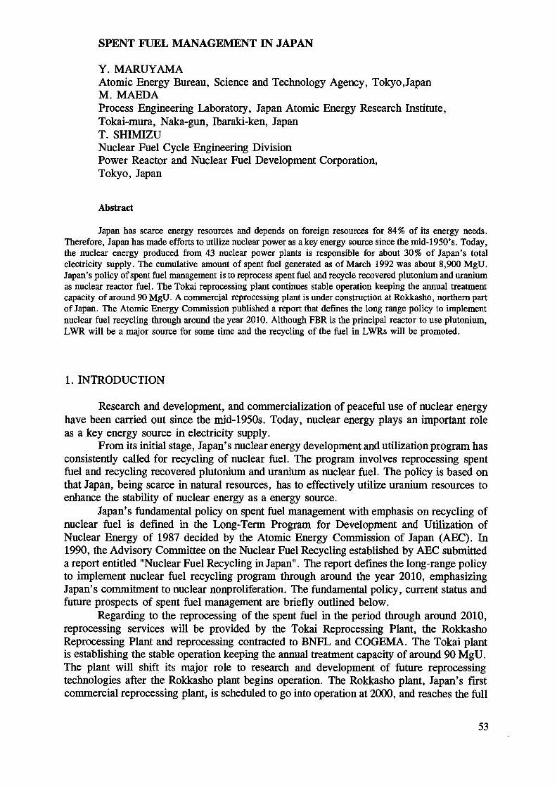
SPENT FUEL MANAGEMENT IN JAPAN
Y. MARUYAMAAtomic Energy Bureau, Science and Technology Agency, TokyojapanM. MAEDAProcess Engineering Laboratory, Japan Atomic Energy Research Institute,Tokai-mura, Naka-gun, Ibaraki-ken, JapanT. SHIMIZUNuclear Fuel Cycle Engineering DivisionPower Reactor and Nuclear Fuel Development Corporation,Tokyo, Japan
Abstract
Japan has scarce energy resources and depends on foreign resources for 84% of its energy needs.Therefore, Japan has made efforts to utilize nuclear power as a key energy source since the mid-1950's. Today,the nuclear energy produced from 43 nuclear power plants is responsible for about 30% of Japan's totalelectricity supply. The cumulative amount of spent fuel generated as of March 1992 was about 8,900 MgU.Japan's policy of spent fuel management is to reprocess spent fuel and recycle recovered plutonium and uraniumas nuclear reactor fuel. The Tokai reprocessing plant continues stable operation keeping the annual treatmentcapacity of around 90 MgU. A commercial reprocessing plant is under construction at Rokkasho, northern partof Japan. The Atomic Energy Commission published a report that defines the long range policy to implementnuclear fuel recycling through around the year 2010. Although FBR is the principal reactor to use plutonium,LWR will be a major source for some time and the recycling of the fuel in LWRs will be promoted.
1. INTRODUCTION
Research and development, and commercialization of peaceful use of nuclear energyhave been carried out since the mid-1950s. Today, nuclear energy plays an important roleas a key energy source in electricity supply.
From its initial stage, Japan's nuclear energy development and utilization program hasconsistently called for recycling of nuclear fuel. The program involves reprocessing spentfuel and recycling recovered plutonium and uranium as nuclear fuel. The policy is based onthat Japan, being scarce in natural resources, has to effectively utilize uranium resources toenhance the stability of nuclear energy as a energy source.
Japan's fundamental policy on spent fuel management with emphasis on recycling ofnuclear fuel is defined in the Long-Term Program for Development and Utilization ofNuclear Energy of 1987 decided by the Atomic Energy Commission of Japan (AEC). In1990, the Advisory Committee on the Nuclear Fuel Recycling established by AEC submitteda report entitled "Nuclear Fuel Recycling in Japan". The report defines the long-range policyto implement nuclear fuel recycling program through around the year 2010, emphasizingJapan's commitment to nuclear nonproliferation. The fundamental policy, current status andfuture prospects of spent fuel management are briefly outlined below.
Regarding to the reprocessing of the spent fuel in the period through around 2010,reprocessing services will be provided by the Tokai Reprocessing Plant, the RokkashoReprocessing Plant and reprocessing contracted to BNFL and COGEMA. The Tokai plantis establishing the stable operation keeping the annual treatment capacity of around 90 MgU.The plant will shift its major role to research and development of future reprocessingtechnologies after the Rokkasho plant begins operation. The Rokkasho plant, Japan's firstcommercial reprocessing plant, is scheduled to go into operation at 2000, and reaches the full
53

capacity of 800 MgU shortly after 2000. The designation of reprocessing business of JNFLand the safety of the basic design philosophy of the plant was authorized in December, 1992by AEC as well as the Nuclear Safety Commission (NSC). The construction of the spent fuelstorage facility started in April, 1993, through the safety permit of the design andconstruction method for the first part by STA. Reprocessing contracted to overseas nationsis a transitional measure, since it is Japan's principle to reprocess spent fuel in Japan. R&Drelated to the reprocessing of spent MOX fuel from LWR and FBR will be carried out inclose cooperation with the development of the current technology for the LWR spent fuel.High-level radioactive waste separated from spent fuel in the reprocessing will be disposedof in accordance with the basic principle of the solidification in a vitrified form, followed bythe storage for 30 to 50 years and finally of ultimate disposal in a deep geological formation.As regards spent fuel exceeding the available reprocessing capacity, it will be properly storedand managed until being reprocessed.
The plutonium recovered by reprocessing, will be utilized as nuclear fuel in FBRs,LWRs and ATRs. The FBR is considered to be the principal reactor to use plutonium andefforts for its commercialization will be continued. The LWR will be a major source forsome time in Japan's nuclear power generation program. Therefore, Japan will promoterecycling plutonium in LWRs by steadily developing its recycling technologies andinfrastructures. ATRs will be used for recycling plutonium to enhance the flexibility ofrecycling programs.
2. GENERATION, STORAGE AND TRANSPORTATION OF SPENT FUEL
2.1. Spent fuel generation
As of the end of June 1993, 43 nuclear power plants are in operation in Japan, andthe total generation capacity is about 35 GWe. According to the report written by the ElectricUtility Industry Council, a government advisory organization, nuclear generation capacitywill increase to 50 GWe in 2000, and 72 GWe in 2010. The cumulative amount of spent fuelgenerated was 8,900 MgU as of March 1992. It is estimated from the projection ofgeneration capacity that the annual generation rate from 1991 to 2000 will be roughly 1,000MgU (Fig. 1).
2.2 Storage
2.2.1 Current status and prospectsThe total volume of spent fuel currently stored in nuclear power station pools is
approximately 3,500 MgU. The spent fuel will be shipped to the Rokkasho ReprocessingPlant, when the spent fuel storage facility at the plant goes into operation. The spent fuel forthe other part also continues to be shipped to the Tokai Reprocessing Plant and to overseasreprocessing plants, according to existing contracts.
2.2.2 Research activities on spent fuel storageThe spent fuel surpassing the reprocessing capacity must be properly stored and
managed until being reprocessed. The purpose of the research on spent fuel storage is toprovide flexibility in the spent fuel management.
The research is categorized to:(1) improvement of the existing wet storage technology, and(2) testing and evaluation of dry storage technology.
54
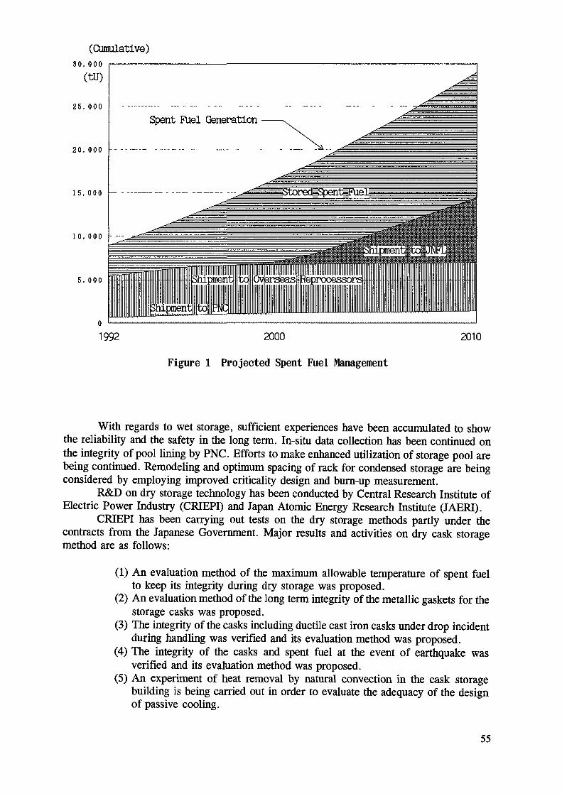
(Cumulative)30,000(tu)
25,000
20,000
15,000
10,000
5. 000
Spent Fuel Generation
iStoredlSpentlFue]
1992 2000Figure 1 Projected Spent Fuel Management
2010
With regards to wet storage, sufficient experiences have been accumulated to showthe reliability and the safety in the long term. In-situ data collection has been continued onthe integrity of pool lining by PNC. Efforts to make enhanced utilization of storage pool arebeing continued. Remodeling and optimum spacing of rack for condensed storage are beingconsidered by employing improved criticality design and burn-up measurement.
R&D on dry storage technology has been conducted by Central Research Institute ofElectric Power Industry (CRIEPI) and Japan Atomic Energy Research Institute (JAERI).
CRIEPI has been carrying out tests on the dry storage methods partly under thecontracts from the Japanese Government. Major results and activities on dry cask storagemethod are as follows:
(1) An evaluation method of the maximum allowable temperature of spent fuelto keep its integrity during dry storage was proposed.
(2) An evaluation method of the long term integrity of the metallic gaskets for thestorage casks was proposed.
(3) The integrity of the casks including ductile cast iron casks under drop incidentduring handling was verified and its evaluation method was proposed.
(4) The integrity of the casks and spent fuel at the event of earthquake wasverified and its evaluation method was proposed.
(5) An experiment of heat removal by natural convection hi the cask storagebuilding is being carried out in order to evaluate the adequacy of the designof passive cooling.
55
Major research areas in JAERI are the development of the burn-up credit method toimplement into the design of spent fuel storage facility, and the improvement of doseevaluation methodologies of public due to skyshine and direct radiation from large scalestorage facility.
2.3 Transportation
A part of spent fuel generated in Japan has been transported to the above mentionedreprocessing plants, and its cumulative quantity up to now becomes about 5,400 MgU. Thespent fuel amounting to 4,700 MgU has already been shipped to overseas reprocessors, andthe other to the Tokai Reprocessing Plant. From this year to around 1998, 900 MgU of spentfuel is scheduled to be delivered additionally to overseas reprocessing plants.
3. REPROCESSING
3.1 Tokai Reprocessing Plant
The Tokai plant, which is the first reprocessing plant in an industrial scale in Japan,is owned and operated by Power Reactor and Nuclear Fuel Development Corporation (PNC).The plant, with a capacity of 0.7 Mg/d went into the hot test operation in September 1977and was commissioned in January 1981. Although the plant has experienced several troubleswith long interruptions, the total amount of 680 Mg of spent fuel including 5 Mg of MOXfuel from Advanced Thermal Reactor (ATR) "FUGEN" has been reprocessed by the Fiscal1992 (Fig.2).
The major troubles encountered in the Tokai plant were due to the corrosion ofprocess equipments, an acid recovery evaporator and two dissolvers. The phenomena ofcorrosion were investigated, new corrosion resistant material was developed, and theprocedure for fabrication and welding has been modified and improved step by step.
t-U300
200
100
<=•
t-u900
600
300
1977 78 79 80 81 82 83 8U 85 86 87 88 89 90 91 92 FYFigure 2 Operation of Tokai Reprocessing Plant
56

Replacements of the acid recovery evaporator were carried out by using the new corrosionresistant material. Remote controlled devices were newly developed to repair the defectivedissolvers and the in-situ repairing work for the high active equipment was successfullyconducted.
As the result of overcoming those difficulties, the plant operation has been satisfactorywith the annual processing amount of 50 to 70 Mg since 1985. However, aiming at moresteady operation and improvement of plant efficiency, further refurbishments were consideredto be necessary. The following large scale maintenance works were carried out in thescheduled intervention period from 1988 to 1989:
(1) Replacement of acid recovery evaporatorThe acid recovery evaporator had been replaced twice. Expecting longer life, theevaporator was replaced with a new one made of Ti-alloy which has excellentcorrosion resistance compared to the conventional stainless steel.
(2) Replacement of plutonium evaporator towerThe plutonium solution evaporator tower was replaced with a new one made ofTi-alloy and welded to the boiler made of titanium.
(3) Installation of additional pulsed-filterThe pulsed-filter used in the clarification process requires periodic maintenanceworks such as washing and replacement of filter element, which affect the plantefficiency. A similar pulsed-filter was installed additionally to make dual system.
(4) Replacement of internal parts of shearing machineMajor internal parts were renewed remotely, considering possible improvementsfor prevention of powder deposition and for easiness of remote maintenance.
(5) Modification of acid recovery distillatorThe distillator configuration was modified to separate the boiler portion from thecolumn so that the periodic inspection and necessary repair can be conductedmore easily. The plant resumed operation in the end of September 1989. Theplant is expected to process about 90 MgU of spent fuel annually.
3.2 Commercial reprocessing plant and radioactive waste management facility
The Japan Nuclear Fuel Ltd. (JNFL) has started construction, in Rokkasho village,Aomori-Prefecture, of a reprocessing plant with a capacity of 800 MgU/year from April1993 and of a radioactive waste management facility from May 1992 which will store thevitrified waste to be returned from France and the U.K. reprocessors under the reprocessingcontracts with Japanese electric companies.
(1) DesignThe basic design for the reprocessing plant started in February 1987, and finished
in January 1989. The detailed design work started in January 1989, and finished in December1992. The basic design for the waste management facility started in September 1987, andfinished in November 1988. Detailed design work started at the end of the basic design, andcompleted in August 1991.
(2) Principal facility specification- Reprocessing plant
Method: PUREX methodCapacity: 800 MgU/year
4.8 MgU/day (max)- Spent fuel storage pool: 3,OOOMg-U
57
- Spent fuel:Residual enrichment: less than 3.5wt%Cooling time: over 1 year before receiving
over 4 years before reprocessingBurn-up: 55,OOOMWd/t-U (max)
45 ,OOOMWd/t-U(average)- Radioactive waste management facility
Waste: vitrified wasteCapacity: 1,440 canisters
(three thousand and several hundred canisters infuture)
Cooling method: natural ventilation(3) Technology
To adopt the best technology, JNFL made efforts to review and analyze variousreprocessing techniques available in Japan and abroad. JNFL finally decided to adopt themajor technologies for the reprocessing plant as follows:
- Main reprocessing process: SGN(France)- Reduced pressure evaporation: BNFL(U.K.)- Iodine removal process: KEWA(Germany)- U & Pu mixed denitration: PNC(Japan)- Spent fuel storage pool: HITACHI et al.(Japan)- High-level radioactive waste vitrification: PNC(Japan)
(4) SiteSite is 380 ha in area and is located to the south of a site for uranium enrichment
plant and low-level radioactive waste disposal center both being operated by JNFL. Anenvironmental assessment for the site completed in August 1989.
(5) AuthorizationJFNL applied for the authorization of reprocessing and radioactive waste
management businesses through STA to the Prime Minister in March 1989. The first-stepreview by STA of the application for radioactive waste management fi nished in May 1991and the second-step review by AEC and NSC finished in April 1992. The first-step reviewby STA for reprocessing completed in August 1991, and the second-step review by AEC andNSC finished in December 1992.
(6) ScheduleSchedule of these facilities are shown in Fig.3.
a. Reprocessing plantThe plant is scheduled to receive spent fuel from April 1996 and to go intooperation in January 2000.b. Radioactive waste management facilityAccording to the current plan by JNFL, the facility is scheduled to go intooperation in February 1995.
3.3 R&D activities in LWR fuel reprocessing
3.3.1 R&D activities in PNCThe Tokai Reprocessing Plant has a role as the pilot plant for establishing
reprocessing technology in Japan. Many R&D activities in this field are carried out in theTokai plant and related facilities for plutonium conversion and waste treatment such askrypton recovery, vitrification and bituminization. Two kinds of R&D programs are carried
58

^̂ \Fiscal Year
Land Prepararion
Reprocessing PlantSpent Fuel PoolMain Plant
Radioactive WasteManagement Facility
1992
Const
1993
Const
ructio
199U
ructio
n A
1995 1996
Operationn T
Con
Opérât
struct
ion
1997
ion
1998 1999
OperaT^
2000
tion
2001
Figure 3 Construction and Operation Shedule of Reprocessing Plant andRadioactive Waste Management Facility at Rokkasho
into effect : short- and medium-term programs to improve plant operability and long-termprograms to pursue advanced technology. The short- and medium-term programs includedevelopments of components with higher reliability, remote repair and in service inspection,expansion of engineering data base, operational support system for main process, etc. Forthe Rokkasho Reprocessing Plant, PNC also plays an important role as a technical advisorbased on its technical know-how and experiences gamed through the operation of the Tokaiplant.
Because the demand for the Tokai plant of LWR fuel reprocessing is supposed todecrease once the Rokkasho plant starts operation, the principal role of the Tokai plant willbe gradually shifted to more extensive R&D activities mainly for advanced technology suchas reprocessing of high burn-up fuel and MOX fuel. In the long-term prog rams, emphasisis placed on advanced engineering for head-end process including mech anical chopping,dissolution, off-gas treatment, and clarification. At the Tokai plant, the head-end process isthe main area to lower the performance of the plant and it has caused frequent shut-downsof operation. The study to add a new head-end equipment to the Tokai plant is started todemonstrate the advanced equipment in hot environment.
3.3.2 R&D for a large scale reprocessing plantIn order to ensure stable and reliable operation of the Rokkasho plant, JNFL has
been promoting various R&D, partly with financial support by the government and electricutility companies. Cold tests (including tests with uranium) have been conducted for the mainequipments on an actual plant scale.
Demonstration tests of head-end process equipment and of annular pulsed column arescheduled to be conducted using mock-up facilities. Other research activities are be ingperformed to cover waste treatment technologies, process development for environ mentalsafety, equipment materials and instrumentation technologies.
3.3.3 R&D activities in JAERIJapan Atomic Energy Research Institute (JAERI) has conducted various activities to
support the nuclear fuel cycle program, with emphasis on safety research and fundamentalresearch.
59

(1) Safety researchThe major purpose of the safety research in JAERI are to provide the sound
technical basis for safety criteria and evaluation, and to improve the safety of the currenttechnology. The safety researches for the former purpose include criticality experiment toaccumulate safety evaluation data and various safety demonstration tests of criticality, fireand explosion under simulated accident conditions, and of extraction contactor in maloperatedconditions. In these researches, computer codes and data base have been developed for theassessment of radioactive source term, effect on confinement or mitigation system, and ofprocess behavior in anticipated transients to allow reliable safety evaluation with reasonablesafety margins. Research on shielding and burn-up credit also started.
The research for the latter purpose is focused on improvement of theenvironmental safety and the waste management, covering such areas as efficient control ofvolatile radioactive elements such as carbon and iodine, salt free processing of aqueouseffluent in a closed system. A research project on distribution behavior of volatile ordiffusive nuclide in reprocessing high burn-up fuel is also starting in a small scalealpha-gamma facility.
(2) Fundamental researchThe target of the fundamental research in JAERI is to modify the Purex system
in the short range scope and to propose some innovating system in the long range scope, byapplying advanced process in the key area of reprocessing and waste management. Aresearch to control neptunium and technetium in Purex system is continued to simplify thesystem. The partitioning research of high level liquid waste is being directed towardintegration with reprocessing and incineration of long-lived radioactive nuclides.
The reseach on waste treatment concerns mostly with TRU waste management.The resear ch includes fine separation of TRU elements from aqueous solution to reduceTRU was te volume and nondestructive assay of trace amount of TRU in solidified waste.The other activities cover development of computer code and data base to simulate Purexprocess for high burn-up and MOX fuel, fundamental data collection in the TRU solutionchemistry, application of laser technologies to separation process and in-line mo nitoring.
(3)NUCEF projectIn order to support these research activities, a new research facility, Nuclear Fuel
Cycle Safety Engineering Research Facility (NUCEF) is being constructed. Major researchprograms in the facility are nuclear criticality experiment, advanced reprocessing processdevelopment and research for improved TRU waste management. For the research programs,NUCEF is equipped with two critical facilities, a stationary criticality assembly STAC Y anda transient criticality assembly TRACY, which are fueled with uranium and/or plutoniumunitrate solution. It is also equipped with alpha-gamma cells BECKEY to handle a smallquantity of spent fuel for the advanced reprocessing research, and a number of glove boxesfacilitating various research with TRU elements.
3.4 R&D activities in FBR fuel reprocessing
In the FBR fuel reprocessing PNC has developed its own process and equipment aswell as remote handling techniques through large scale cold mock-up tests and laboratoryscale hot tests on the basis of the experiences accumulated in the Tokai Reprocessing Plant.The Recycle Equipment Test Facility (RETF), adjacent to TRP, is under designing forconducting large scale equipment tests under hot conditions in order to improve the technicallevel.
60

3.4.1 Process research and development
(1) R&D facilitiesThe Chemical Processing Facility (CPF) has been devoted for "hot" process test
by using not only 'JOYO' fuel since 1982 but also Phénix fuel up to 94,000 MWd/t sinceOctober 1986. In the Engineering Demonstration Facilities (EDF-I, II, III), many kind s ofengineering tests of process equipment and remote maintenance system have been carried out.
(2) Head-end processA laser-beam disassembly system is adopted to remove hexagonal wrapper before
fuel bundle shearing. Disassembly tests on dummy fuel assemblies have been conducted toverify the adequacy of the proposed disassembling sequence. A continuous rotary dissolverhas been developed to improve the efficiency of the fuel dissolution process. Uraniumdissolution tests have been conducted with the prototype rotary dissolver in the PNC/DOEcollaboration.
(3) Chemical separation processDevelopment of centrifugal contactor system has been continued including the
detailed design of contactor units for use in the RETF.As a part of 'salt free' process development, experiments with a electrolysis cell
is in progress to demonstrate the feasibility of electrolytic re-oxidation of plutonium usingcerium as its substitute.
(4) Remote maintenance technologyThe development of remote maintenance system has been conducted to establish
advanced remote maintenance concept with rack module system and servo-manipulatorsystem for application to new hot test facilities and future plants. The Prototype-IIservo-manipulator system has been tested at EDF-III. A full scale mock-up of the rack forRETF was fabricated and installed in EDF-III. Remote handling tests have been conductedon the mock-up rack as well as on the components and remote connector banks mounted onit.
(5) Material developmentCorrosion studies on various materials for reprocessing applications have been
continued in cold and hot conditions.
3.4.2 Plant design
(1) Recycle equipment test facility (RETF)The result of research and development proved that hot demonstration of newly
developed large scale components was necessary for steady operation of a pilot plant. Fromthis viewpoint, PNC started the design of RETF. The design is now at the final stage. TheRETF is a test facility for key components and process of FBR fuel reprocessing and willbe operated to collect hot data with irradiated FBR fuel from JOYO and MONJU. Remotetechnology will be adopted so that the test components in the hot cell are interchangeable.The operation will be initiated around 2000.
(2) FBR recycling pilot plantThe purpose of the FBR Fuel Recycling Pilot Plant is to demonstrate the whole
plant availability and to evaluate the economical efficiency of FBR fuel reprocessing forrecycling spent fuel from FBR. It is scheduled to begin operation after 2000.
61

4.RECYCLING OF RECOVERED PLUTONIUM AND URANIUM
4.1 Future nuclear fuel recycling programs
4.1.1 Basic view
(1) Demand sidea. FBRThe FBR has been developed as the main reactor for nuclear power generation
in the future and is considered to be the principal reactor to use plutonium. Efforts will becontinued for commercializing the FBR in the future.
- FBRs utilize uranium resources highly efficiently.- It is also expected that if transuranic elements could be recycled by FBRs,radioactive waste management could be improved.b. LWRLWRs will be a major source for some time to come in Japan's nuclear power
generation program. Therefore, Japan will promote recycling in LWRs with the objectivesof steadily developing its recycling programs.
- The recycling in LWRs can play a role as an energy source in Japan's nucleargeneration system.- The technologies and infrastructures required for commercial-scale recycling canbe developed with the aim of commercial operation of FBRs.c. ATRATRs will be used for recycling plutonium to enhance the flexibility of recycling
program.- ATRs have flexibility in fuel use.
(2) Supply sidea. Rokkasho Reprocessing Plant- Japan's main source to supply plutonium- indispensable to carry out the FBR programs, the principal element of Japan'snuclear fuel recycling programs, from a long-range view point - continuouslyprovide plutonium necessary for recycling in LWRs and for R&D of ATRsb. Overseas reprocessing- a transitional measure- supply plutonium necessary for R&D of FBRs and ATRs and for recycling inLWRsc. Tokai Reprocessing Plant- continues to supply plutonium basically for R&D of FBRs and ATRs - will shiftits major role to R&D of future reprocessing technologies, after the Rokkashoplant begins operation at the end of 1990s.
4.1.2 Recycling programs through around the year 2010Since it is important that recycling programs be transparent in order to secure a wide
understanding both domestically and internationally, the programs which are deemedappropriate under current circumstances are presented. These programs will naturally beaffected by the changes of circumstances surrounding the programs in the future.
Prospect of Demand and Supply of Accumulated Amount of Plutonium (Fissile)through the Year 2010:
62

(1) Demand side around 80-90 Mg of Puf (fissileplutonium)
a. FBR and ATR:FBR :
JOYO and MONJU around 12-13 Mg of PufDFBR and reactor succeeding DFBR around 10-20 Mg of Puf
(Main factors affecting the plutonium requirement aretiming of introduction and the scale of the reactorsucceeding the DFBRs.)
ATR:FUGEN and DATR a little less than 10 Mg of Puf
b. LWR: around 50 Mg of PufGradual and systematic expansion of recycling programs by LWRs-Mid 1990s 1 PWR(800MWe class or bigger) 1/4 core
1 BWR(800MWe class or bigger) 1/4 core-End of 1990s 4 LWRs(1000MWe class) 1/3 core-Shortly after 2000 12 LWRs(1000MWe class) 1/3 core
(2) Supply side around 85 Mg of PufThe amount of plutonium supplied in the future depends on the type and amount
of spent fuel actually reprocessed. Therefore, it is difficult to calculate accurately the amountof plutonium supplied. However, the appropriate estimates currently possible are presentedbelow.
-Tokai Plant around 5 Mg of Puf-Rokkasho Plant around 50 Mg of Puf-Overseas Reprocessing around 30 Mg of Puf
Considering that an adequate amount of running stock is required in the actualsupply-demand balance of plutonium, the estimated total supply of about 85 Mg of Puf isconsidered to be necessary to carry out nuclear fuel recycling programs in Japan in thefuture, which would require around 80 to 90 Mg of Puf.
4.1.3 Progress of FBR MONJU projectThe construction of MONJU, the loop type LMFBR 280 MWe was completed in the
end of April 1991. Pre-operational tests started in May. Pre-operational tests consist offunction tests and start-up tests. The purpose of function tests is preparation for start-up testsafter initial fuel loading. Function tests are conducted in different atmospheres (air at roomtemperature, argon and sodium). The reactor is scheduled to reach initial criticality in spring1994 and full power operation in 1995.
4.2 Conversion of plutonium
To use plutonium recovered from reprocessing, the development of conversiontechnology is essential, together with reprocessing and MOX fuel fabrication technologies.PNC is the first company in the world in developing the co-conversion technology usin g themicrowave heating denitration process (MH method), which converts plutonium nitrate anduranyl nitrate solution to MOX. Compared with the conventional methods, this process issimple and generates less liquid waste.
The construction of Plutonium Conversion Development Facility (PCDF) wascompleted in February 1982. Approximately 3,500 kg of plutonium powder have beenconverted and transferred to the PNC's MOX fabrication facilities by the March 1993. MOXpowder for MONJU has been converted in PCDF.
63

4.3 MOX fuel fabrication
The development of MOX fuel fabrication by PNC started at the Plutonium FuelDevelopment Facility (PFDF) in 1965. The cumulative amount of MOX fuel produced byPNC was approximately 123 Mg, and 61,000 fuel rods had been successfully irradiated bythe end of March 1993. The Plutonium Fuel Production Facility (PFPF) for thedemonstration of mass production technology was completed in 1987. The PFPF adoptedfully remote and automated operation technologies. The FBR line of PFPF with a capacityof 5 Mg-MOX/y started operation in 1988 to supply fuel for the prototype FBR MONJU andJOYO. Fabrication of MOX fuel for MONJU initial loading is under way in PFPF. The ATRline of PFPF is now under construction.
As mentioned above, the technology related to MOX fuel fabrication has beenestablished in Japan. Aiming at establishment of plutonium utilization system in the future,however, further R&Ds are required to commercialize MOX fuel fabrication including thesafe handling of plutonium. At PFDF research will be continued on manufacturing fuels withnew materials, new welding techniques, and other aspects of plutonium fuel fabrication. And,developments of advanced fabrication equipment and instruments will be carried out. ThePFPF will serve as a bridge leading to commercialization of MOX fuel fabrication byestablishing remote controlled and automated operations as well as better quality control, thusfurthering the safety and economy of fabrication.
Corresponding to the operation of the Rokkasho Reprocessing Plant, domestic MOXfuel fabrication for LWRs must also be developed into a commercial operation. A domesticfabrication plant with a capacity of around 100 Mg of MOX fuel per year must be incommercial operation around 2002. PNC's MOX fuel fabrication technology must besmoothly transferred to the private sector.
4.4 Utilization of recovered uranium
Recovered uranium can be converted to uranium hexafluoride followed byre-enrichment and re-conversion, be mixed with enriched uranium or be mixed withplutonium to be recycled as MOX fuel. All these options have been studied. Re-enrichmentis considered to be the best method of recycling uranium in terms of economy and theamount of recovered uranium usable. About 360 Mg of recovered uranium will be convertedto uranium hexafluoride from the year 1994 to 1997 by PNC under a contract with Japaneseutilities, as a part of efforts for the establishment of commercial-scale recycling of recovereduranium by re-enrichment.
5. MANAGEMENT OF HIGH-LEVEL RADIOACTIVE WASTES
High-level radioactive wastes (HLW) separated in reprocessing are now stored in theform of solution at the Tokai Reprocessing Plant. These wastes are to be vitrified and storedfor cooling for a period of 30 to 50 years at a storage facility. Then HLW will be finallydisposed of into deep geological formations with multi-barrier system.
With regard to the development of technology for the treatment of HLW, theconstruction of an experimental facility for the vitrification in PNC Tokai (TVF) wascompleted in April 1992 and will be into a test run with HLW in 1994. As for HLWdisposal, the Advisory Committee on Radioactive Waste of the Japan Atomic EnergyCommission (AEC) released a report entitled "Overall Program for High Level RadioactiveWaste Disposal" in August 1992. In the report, HLW disposal procedures and schedule, theroles of relevant organizations, and relevant research and development programs are shown.
64
(1) Implementation of Disposal
(a) Roles of Relevant OrganizationsGovernment: is to take overall responsibility for appropriate and steadyimplementation of the progaram, as well as enacting any laws or policies requiredin this connection.PNC: is to ensure smooth progress of research and development projects and tocarry out studies of the geological environment.Electric Supply Utilities: are expected not only to secure the funds for diposal butalso to share the responsibility even at the stage of research and development ,in accordance with their role as waste producers.With respect to joint efforts of the organizations concerned, a Council forpromoting HLW disposal has been set up by the government, the utilities, andPNC as a forum for discussing practical measures and exchanging views andinformation.
(b) Implementation Organization: Its Form and Timing of EstablishmentForm: It is to be discussed further, taking into consideration such as guranteeinglong-term efficiency, the responsibilities of the waste producers and appropriateconsideration of R&D results.Timing of Establishment: It is considered appropriate to plan the establishmentof the implementing organization around the year 2000, giving due considerationto the construction schedule for a responsibility, progress in R&D and the overallsocial and political situation.
(c) Preparatory OrganizationThe Council for promoting high-level waste disposal should, in the near futufre,examine the form and other aspects of the implementing organization and shouldset up a preparatory organization as early as possible.
(d) Procedure for Implementing Geological DisposalGeneral procedure for geological disposal are as follows: The implementingorganization will conduct the preliminary investigation at potentially suitablelocations and subsequently confirm the results of site selection as the designatedsites(s). Prior to government confirmation, the implementing organization willobtain the acceptance of local communities in the siting region(s) by clearlyexplaining the aim and the results of the selection process. The implementingorganization will conduct site characterization studies and will demonstratedisposal technologies in underground facility at the designagted site(s). Theimplementing organization will design a repository and apply for an operatinglicence. The government, in turn, will conduct the safety investigations forgranting a licence. The overall tune schedule for disposal foresees the start ofrepository operations sometime after the year 2030, but no later than the mid2040s: this takes into account the time up to construction and forthcomingdevelopments in the nuclear energy situation in Japan.
(2) Procedure for R&D
(a) Evaluation for R&DPNC's first progress report, submitted in 1992, should clarify the current statusof R&D, as well as results obtained to date. PNC's second progress report isscheduled to be submitted before the year 2000. The government plans to set upa special committee to review the progress report.
65

(b) The role fo the Deep Underground Research FacilityThe deep underground research facility is essential for a comprehensive study ofthe geological environment since they l)provide a detailed understanding of thegeoscientific parameters which are considered relèvent to deep undergrounddisposal, 2) allow the models used for safety assessment to be improved andvalidated and 3) allow a wealth of scientific data to be accumulated on the deepgeological environment. There should be a clear separation between plans forsuch deep underground research facilities and those for a waste repository. It isdesirable to have more than one such research facility.
(3) Other TopicsDisposal Costs, Institutional Control of a Repository, Partitioning andTransmutation of Actinides. Local Public Relations, are also included in thisreport.
66
SPENT FUEL MANAGEMENT IN THE REPUBLIC OF KOREA:PAST, PRESENT AND FUTURE
WON J. PARKKorea Institute of Nuclear Safety,Daeduk Science Town, Republic of Korea
Abstract
The continuous expansion and development of nuclear power program in the Republic of Korea haveresulted hi generation of the significant volume of the nuclear wastes. At present Korean program is bestcharacterized as a heterogeneous nuclear power sources with PWR and CANDU. Like other countries, spentfuel discharged from nuclear power plants is one of the impending problems to be solved due to their inherenthigh radioactivity and long half-life. Great efforts have been made to solve effectively these problems in spentfuel management which might be encountered within foreseeable future, taking advantages of our mixed nuclearpower system. In this presentation, the current status of spent fuel management in the Republic of Korea arediscussed, and the related research activities are briefly introduced.
1. BACKGROUNDSince the year of 1978, nine nuclear power plants (8 PWRs and 1 CANDU), whose
total generating capacity is about 7.6 GWe, have been in operation in the Republic of KoreaAnd other 4 units of 1000 MWe class PWRs and 3 units of 700 MWe CANDUs arescheduled for commissioning by the end of this century. By then, total 16 NPPs consisting12 PWRs and 4 CANDUs are expecting to be on electricity grid in the Republic of Korea.In addition, Korea Electric Power Corporation (KEPCO) announced, at July of 1991, thelong-term electricity power development plan to build nine more nuclear power plants( 6Korean standard 1000 MWe PWR and 3 CANDU - 700 MWe) during the period from theyear of 2001 to 2006 to cope with the impending power demand. As shown in Table 1, thefuture nuclear power generation capacity is forecasted to be at least 23 GWe with 20 PWRsand 7 CANDUs in the year of 2006. With this nuclear power program, the nuclear share willbe more than 40 % of the total generating capacity, and about 55 % of electricity in theRepublic of Korea will be produced by nuclear power since most of nuclear power plants aregoing to be base loaded.
In contrast to the countries highly experienced in nuclear technology, employing spentfuel reprocessing as basic strategies for spent fuel management, the Republic of Korea hasdecided to construct an spent fuel interim storage facility by the end of this century. In whichspent fuels will be stored for several decades until globally acceptable strategy and thetechnology are established.
At present, spent fuel discharged from the nuclear power plants is currently beingstored in At Reactor (AR) water pools. The total spent fuel storage capacity of AR facilitiesof those current 9 nuclear units is about 4,000 MgU. About 2,000 MgU of spent fuel fromthese reactors have been accumulated up to now. This presentation shows overall effort toconstruct a long-term strategy for back-end nuclear fuel cycle under the present atmospherethat conventional reprocessing is not foreseen in the near future.
2. NATIONAL STRATEGIES
The Korean government, recognizing that a national problem exists due toaccumulation of commercial spent fuel assemblies, and that the final decision for spent fuel
67

Table 1. Nuclear Power Plants' Installed Generation Capacity in Korea
Status
InOperation
UnderConstruction
Planned
Long TermProjection
Nameof
Plant
KorilKori2Wolsung 1Kori3Kori4Yeongkwang 1Yeongkwang 2UljinlUljin2
Yeongkwang 3Yeongkwang 4Wolsung 2Wolsung 3Wolsung 4Uljin3Uljin4
Yeongkwang 5Yeongkwang 6
CANDU-5CANDU-6Standard PWR-1Standard PWR-2Standard PWR-3Standard PWR-4Standard PWR-5Standard PWR-6CANDU-7
Reactor
Type
PWRPWRPHWRPWRPWRPWRPWRPWRPWR
PWRPWRPHWRPHWRPHWRPWRPWR
PWRPWR
PHWRPHWRPWRPWRPWRPWRPWRPWRPHWR
StartofOperation
1978.41983.71983.41985.91986.41986.81987.91988.91989.9
1995199619971998199919981999
20002001
200220032002200320032004200520062006
Capacity
(MWe)
587650679950950950950590950
1000100070070070010001000
10001000
700700100010001000100010001000700
CumulativeCapacity(MWe)
5871.2371,9162,8663,8164,7665,7166,6667,616
8,6169,61610,31611,01611,71612,71613,716
14,71615,716
16,41617,11618,11619,11620,11621,11622,11623,11623,816
management will not be made in the foreseeable future, amended the Atomic Energy Act inMay of 1986. In the amended Act, the government would take the responsibility for nationalspent fuel management and the financing of the programs for radioactive waste managementwould be assured by placing a fee from nuclear power utility, KEPCO as much as 2 won perkwh ( - 2.5 mil US$ per kwh ). Further the important principle that an Away From Reactor(APR) spent fuel interim storage facility must be constructed by the end of 1997 has beenestablished by the 220th Atomic Energy Committee (AEC) on July, 27 of 1988.
At the 221th AEC meeting in Dec. of 1988, "Wet" storage option for the first interimstorage facility was employed and long-term plan for the facility until the year of 2000 wasapproved. As well, dry interim storage option would be also considered in near future.Through the technico - economic assessment, an optimal capacity as much as 3,000 MgU asthe first storage capacity of these interim storage was determined. Additional expansion ofcapacity will be planned as the first storage capacity becomes filled up.
However, public concern on nuclear power in the Republic of Korea has beendrastically, with the anti-nuclear movement being grown by environmental protection groups.Even though the necessity for nuclear electricity has been acknowledged by the majority ofthe general public, opposition by local resident living near candidate site of spent fuel interimstorage facility have become intensified. Great effort done to select the best candidate site
68

have become in a vain up to now. As the result, the first APR spent fuel storage facility isdestined to be delayed for several years and not to meet the original schedule which will behi operation by the beginning of 1998. Nevertheless, the above-mentioned national strategyhas been still officially unchanged.
Consequently, the present strategies for spent fuel management in the Republic ofKorea is to store and to decay in At-Reactor storage pool for the time being, and transferredto the Away-From-Reactor (APR ) interim storage facility and stored for several decades.In one word, the integrated spent fuel management with "Wait and See" strategies has beenstill adopted as the best one among several strategies which the Republic of Korea has takeninto consideration for last decade.
3. PRESENT STATUS OF SPENT FUEL IN THE REPUBLIC OF KOREA
Since the first commercial nuclear power reactor, Kori -1, entered operation in 1978,the Korean nuclear power program has witnessed quite rapid expansion. Currently we have9 nuclear reactor units in operation and 7 units under construction, and also a plan to buildeleven more nuclear power plants up to the year 2006. Based on the current program, about3,200 MgU of spent fuel projects to accumulate by the year of 1997 and, by the year 2000it reaches to about 4,000 - 4,500 MgU. Moreover, the cumulative amounts of spent fuelsdischarged from total 16 units which expect to be in operation by 2,000, excluding the 11units at the planning stage, will be approximately 20,000 MgU. From these projections, themost serious problem we are going to face, therefore, must be the shortage of each ARstorage capacity for the spent nuclear fuel arisings.
The accumulated amount of spent fuels up to now, the annual spent fuel arisings andthe AR storage capacity of each nuclear power station are given in Table 2.
Table 2. At-Reactor Spent Fuel Storage Status in Korea (As of July. 31,1993 )- unit : MTU
NPP
Kori-1-2-3-4
Yeongkwang -1-2
Uljin-1-2
Weisung*!
PWRCANDU
Total
AR StorageCapacity
225376316316
316316
200378
1,526
2,4431,526
3,969
AccumulatedNo. up to now
129150220134
133125
8962
951
1,042951
1,993
AnnualArisings
17172222
2222
2222
95
16695
261
69

4. SPENT FUEL STORAGE PLAN IN THE REPUBLIC OF KOREA
4.1 Expansion of existing AR storage capacity
Expansion of spent fuel storage capacity in existing water basins is a straightforwardand attractive solution to meeting the needs for additional storage capacity in the Republicof Korea. The primary advantage of this approach is that it makes use of the existing storagefacility, minimizing the capital investment required to obtain the additional capacity fordischarged spent fuel prior to the operation of the planned spent fuel interim storage facility.Among a couple of primary methods, the replacement of non-poisoned racks with the highdensity storage racks employing boron to absorb neutrons and allow even closer spacing ofthe stored assemblies have been being carried out at sites. The expansion program at the Kori-3 at Kori site, Uljin-1 and- 2 at Uljin site had been done or are underway to be completedin the former half of the 1990's.
The Kori - 3 has been in commercial operations since 1985. The unit owns a fuelbuilding presently equipped with normal storage racks with a capacity of 746 fuel assemblies.157 of the storage cells are available as full core reserve. At this time, the unit has currently536 spent fuel assemblies stored. Therefore it is intended to additionally install boratedstainless steel fuel storage racks in the vacant space of the Kori -3 spent fuel pool, which isreserved for the extension of the storage capacity in the future. After installation of newracks, Kori -3 fuel building will be capable of accumulating the capacity of 1207 spent fuelassemblies in a long run.
In case of Uljin site, the installed normal racks had been already replaced at unit -2with boraflex. And the unit -1 will be replaced with either boral or borated stainless steeltype poisoned racks. The final expanded capacity up to about 890 assemblies each will beable to accommodate the spent fuels discharged from Uljin-1 and Uljin-2 until 2003.
4.2 Dry Storage for CANDU Spent Fuel
As for Wolsung NPP which began its commercial operation in 1983, about 5,000bundles of irradiated fuels are annually discharged into spent fuel bay and total accumulatedbundle amounts to be around 50,000 bundles. However, because the capacity of the existingspent fuel bay is quite limited, it is very urgent to expand the storage capacity of the plant.Among two methods to store irradiated CANDU fuel such as traditional storage in waterbasin and dry storage in concrete canisters, the latter has been selected for interim storagefor CANDU spent fuel as cooled as 7 years old since 1992. The canister area can bepresently accumulated up to 60 dry concrete canisters, which is to be used to store spent fuelby the end of century. We expect to dry - store approximately 40,000 bundles of CANDUfuels in Wolsung site.
The canister is a cylindrical reinforced concrete shell with a capacity to store ninesealed baskets each containing 60 bundles of CANDU 6 fuel. It has an internal liner of 44inch diameter carbon steel pipe. The canister is 21.4 ft. high, has 10.1 ft. outside diameter,and has an inner cavity 43.25 inches in diameter. It provides a combined shielding ofconcrete and steel. The opening at the top is round and sized to accept the fuel transfer flaskduring loading. Both the canister plug and the canister cover plate are manuallysealed-welded to the liner at the completion of all operations, and the IAEA safeguard sealsare installed.
Following are design requirement and design data of the canister to meet:1) design life of 50 years2) no release of radioactive material from the canister under normal operatingconditions
70
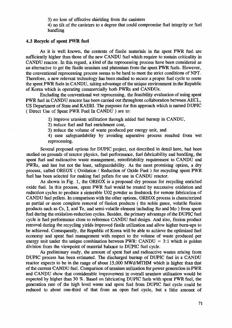
3) no loss of effective shielding from the canisters4) no tilt of the canisters to a degree that could compromise fuel integrity or fuelhandling
4.3 Recycle of spent PWR fuel
As it is well known, the contents of fissile materials in the spent PWR fuel aresufficiently higher than those of the new CANDU fuel which require to sustain criticality hiCANDU reactor. In this regard, a kind of the reprocessing process have been considered asan alternative to get the fissile uranium and plutonium from the spent PWR fuels. However,the conventional reprocessing process seems to be hard to meet the strict conditions of NPT.Therefore, a new relevant technology has been studied to secure a proper fuel cycle to reusethe spent PWR fuels in CANDU, taking advantage of the unique environment in the Republicof Korea which is operating commercially both PWRs and CANDUs.
Excluding the conventional wet reprocessing, the feasibility evaluation of using spentPWR fuel in CANDU reactor has been carried out throughout collaboration between AECL,US Department of State and KAERI. The purposes for this approach which is named DUPIC( Direct Use of Spent PWR Fuel In CANDU ) are to:
1) improve uranium utilization through added fuel burnup in CANDU,2) reduce fuel and fuel enrichment cost,3) reduce the volume of waste produced per energy unit, and4) ease safeguardability by avoiding separative process resulted from wetreprocessing.
Several proposed options for DUPIC project, not described in detail here, had beenstudied on grounds of reactor physics, fuel performance, fuel fabricability and handling, thespent fuel and radioactive waste management, retrofittability requirement to CANDU andPWRs, and last but not the least, safeguardability. As the most promising option, a dryprocess, called OREOX ( Oxidation / Reduction of Oxide Fuel ) for recycling spent PWRfuel has been selected for making fuel pellets for use in CANDU reactor.
As shown in Fig. 1, the OREOX is a proposed dry process for recycling enrichedoxide fuel. In this process, spent PWR fuel would be treated by successive oxidation andreduction cycles to produce a sinterable U02 powder as feedstock for remote fabrication ofCANDU fuel pellets. In comparison with the other options, OREOX process is characterizedas partial or more complete removal of fission products ( the noble gases, volatile fissionproducts such as Cs, I, and Te, and semi-volatile element including Ru and Mo ) from spentfuel during the oxidation-reduction cycles. Besides, the primary advantage of the DUPIC fuelcycle is fuel performance close to reference CANDU fuel design. And also, fission productremoval during the recycling yields unproved fissile utilization and allow higher burn-ups tobe achieved. Consequently, the Republic of Korea will be able to achieve the optimized fueleconomy and spent fuel management with respect to the volume of waste produced perenergy unit under the unique combination between PWR: CANDU = 3:1 which is goldendivision from the viewpoint of material balance to DUPIC fuel cycle.
As preliminary study, the amount of spent fuel and radioactive wastes arising fromDUPIC process has been estimated. The discharged burnup of DUPIC fuel in a CANDUreactor expects to be in the range of about 15,000 MWd/MTHM which is higher than thatof the current CANDU fuel. Comparison of uranium utilization for power generation in PWRand CANDU show that considerable improvement in overall uranium utilization would beexpected by higher than 30 %. Based on fabricating DUPIC fuels with spent PWR fuel, thegeneration rate of the high level waste and spent fuel from DUPIC fuel cycle could bereduced to about one-third of that from an open fuel cycle, but a lithe amount of
71
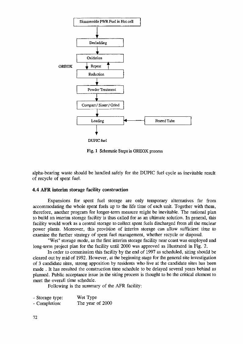
Disassemble PWR Fuel in Hot cell
Decladding
Oxidation
OREOX Repeat
Reduction
Powder Treatment
Compact / Sinter / Grind
Loading Brazed Tube
DUPICfuel
Fig. 1 Schematic Steps in OREOX process
alpha-bearing waste should be handled safely for the DUPIC fuel cycle as inevitable resultof recycle of spent fuel.
4.4 AFR interim storage facility construction
Expansions for spent fuel storage are only temporary alternatives far fromaccommodating the whole spent fuels up to the life time of each unit. Together with them,therefore, another program for longer-term measure might be inevitable. The national planto build an interim storage facility is thus called for as an ultimate solution. In general, thisfacility would work as a central storage to collect spent fuels discharged from all the nuclearpower plants. Moreover, this provision of interim storage can allow sufficient time toexamine the further strategy of spent fuel management, whether recycle or disposal.
"Wet" storage mode, as the first interim storage facility near coast was employed andlong-term project plan for the facility until 2000 was approved as illustrated in Fig. 2.
In order to commission this facility by the end of 1997 as scheduled, siting should becleared out by mid of 1992. However, at the beginning stage for the general site investigationof 3 candidate sites, strong apposition by residents who live at the candidate sites has beenmade . It has resulted the construction time schedule to be delayed several years behind asplanned. Public acceptance issue in the siting process is thought to be the critical element tomeet the overall time schedule.
Following is the summary of the AFR facility:
- Storage type:- Completion:
Wet TypeThe year of 2000
72
CONTENTS
-SrTECHARACTEREATION
- DESIGN
T ÏPFNÇF
-CONSTRUCTION* CIVIL WORK* INSTALL
EQUIPMENT*TEST
OPERATION
- MAINTENANCE
92 93
B>
94
SIC&
95
DETA
<&
96
LED
*•
•4—
-4-
97 98 99
^^
^
00
OL
Fig. 2 Time Schedule for APR Interim Storage Facility Construction
- Main facilities:- reception, storage, support process- cask maintenance, cooling water supply system
- Budget:- construction cost: 220 bil Korea WON ( 275 MIL US$ )- Maintenance cost: 6 bil Korea WON / Yr. ( 7.5 million US $ )
5. RESEARCH AND DEVELOPMENT ACTIVITIES
Related to the integrated spent fuel management, important research activities arebegun and conducted mostly by KAERI. Their main activities are to set up the concrete plansin Korean spent fuel management strategies and to provide additional tool in establishmentof the national fuel cycle policy.
Safety studies related to spent fuel management are being carried out the followingareas such as:
1) source term modeling for APR facility and scenario study,2) study on behavior of defected LWR fuel in wet storage,3) study on radioactive gas treatment system,4) technology development of radiation detection and criticality analysis, and5) structural behavior of APR facility.
In addition, spent fuel storage equipment for storage facility are being developed withrespect to remote-handling, maintenance, and automation technology and cooling andpurification technology.
73
As another important facility, spent fuel technology development facility named STARfacility, plan to be constructed to develop technologies required for long-term dry storage ordisposal of spent fuel at the site of interim storage facility. Design capacity of the facility willbe able to handle up to 48 PWR fuel assemblies per year. Main function of the facility areto handle spent fuel cask, to inspect spent fuel assembly, to check integrity of fuel rods, toconsolidate fuel rods and finally to make package of final products.
6. CONCLUSIONS
As discussed, the Korean nuclear program is best characterized as a heterogeneousnuclear power source with PWR and CANDU reactors. It means that any creative solutionsand technical innovations are widely open. Instead of following previous paths taken by otheradvanced nuclear nations, the Republic of Korea should take advantage of the uniquecircumstance provided by the combination of PWRs and CANDUs. The DUPIC fuel cyclewould be one good example for a kind of opportunities allowed.
Under the current situation in which the best solution for long-term spent fuelmanagement has not been established, both safe storage for the time being of spent fueldischarged from the power plants and the reduction in the volume of spent fuel dischargedper energy unit by improvement in uranium utilization through increased fuel burnup wouldbe the best choices that the Republic of Korea should take. This concept would allowsufficient time to set up further strategies, responding to the gradual development oftechnologies related to this area. On the basis of this policy, the Republic of Korea is tryingto expand the existing AR storage capacity for PWR spent fuel and to have interim storageof CANDU spent fuel in dry concrete canisters. In parallel, DUPIC project has been carriedout to recycle the spent PWR fuel into CANDU reactor even though it is in initial stage.
At present, the first APR spent fuel storage facility seems to be delayed for severalyears and not to meet the original schedule which foresees operation by the beginning of1998. In parallel with the construction of APR facility, much efforts have been made toovercome the shortage of AR storage capacity. The related R & D activities such aspartitioning and transmutation of actinides and fission products, the long-term integrity ofspent fuel, rod consolidation, remote handling and maintenance will be continued astechnological backup to support the spent fuel management strategies.
74

REPROCESSING AND FATE OF LONG-LIVED RADIONUCLIDES
V.N.ROMANOVSKIJV.G. Chlopin Radium Institute,Saint Petersburg, Russian Federation
Abstract
This paper presents a concept of closed fuel cycle with provision for spent fuel reprocessing.Information about reprocessing plants in Russia, including those hi operation and under construction isconsidered. An approach to the management of long-lived radionuclides contained hi spent nuclear fuel (SNF)is described. Implementation of such approach involves partitioning these radionuclides into individual fractions,which makes it possible to use, along with geological disposal, some other methods, transmutation and spaceremoval, in particular. The limits for applicability of geological disposal are determined on the basis of a singlecriterion, namely, reasonable risk with regard to natural and artificial barriers for confinement of nuclideswithin rock massif. To attain the necessary recovery degree of long-lived radionuclides, a modification ofPurex-process and technology for HLW reprocessing is proposed with use of chlorinated cobalt dicarbollyde(ChCoDiC) and phosphine oxides. This flowsheet forms the basis for the project of a high-efficiencyreprocessing plant in Krasnoyarsk.
1. INTRODUCTION
In parallel with the reliability and safety of NPPs, one of the important factorsdetermining development of nuclear power involves the management of spent fuel containingthe most radioactivity of fuel cycle. In the frames of an open fuel cycle, spent fuel isconsidered as a radioactive waste to be disposed off into geological formations. In this casethe elimination of hazardous consequences is hampered by the fact that the whole plutoniumis contained in spent fuel, as well as other actinides being the most hazardous componentsof spent fuel. In terms of conservation under disposal conditions, spent fuel is not anadequately stable material. Closed fuel cycle seems to be preferred from the standpoint ofrecycling the fissile substances and for better solution of the safety problems. In our countrya concept of closed fuel cycle is accepted for the WWER fuel; these reactors will providethe basis for the development of nuclear power hi the next decades. For this purpose, inRussia an infrastructure of nuclear branch has been established, including the capacities forspent fuel reprocessing.
The key problem of safety in closed fuel cycle is connected with the management oflong-lived radionuclides contained in spent fuel, as the closed cycle enables to use alternativemethods for isolation of long-lived radionuclides from the biosphere.
2. THE CONCEPT FOR THE MANAGEMENT OF LONG-LIVED RADIONUCLIDESAND ITS SUBSTANTIATION
A new approach of the flowsheet for spent fuel reprocessing involves partitioning oflong-lived radionuclides contained in spent fuel.
The existing world capacities for spent fuel reprocessing are operated by technologieswhich envisage the solidification of non-separated wastes for subsequent temporary storage,and then for final disposal into geological formations. However the analysis of calculationresults and data on leaching and dissolution rates of different matrices in contact with waterhas confirmed the reliability of such disposal option only for the centuries immediately ahead.
75

The long-term prospects due to complexity and variety of factors seem to be lesscertain, sending in search for radically new solutions of the problem for the isolation oflong-lived radionuclides. One of such solutions is transmutation, i.e. conversion of long-livednuclides into short-lived or stable ones by irradiation in reactor or accelerator. In our countrythe disposal of long-lived nuclides into cosmic space is also under consideration.
It should be emphasized that the implementation of transmutation concept could notrelieve of having to dispose the radioactive wastes into geological formations, as at anyfeasible recovery degree the non-recovered portion of long-lived radionuclides wouldanyway exceed the permissible concentrations required for near-surface storage.
The permissible non-recovered portion of a specified long-lived radionuclides to bedisposed off is determined by the following:
-ecological requirements on the basis of a single criterion, i.e. reasonable risk;-account for natural factors affecting the retention of radionuclides in rock massif;-requirements to artificial barriers and matrices containing the solidified wastes.
The attainment of the recovery degree of radionuclides in compliance with foregoingis a very complicated technical task which needs the application of up-to-date separationtechnologies.
Starting from the above notions, below are presented the general principles of theproposed management of long-lived radionuclides [1,2].
2.1. Approach to the classification of radioactive wastes containing long-livedradionuclides according to reasonable risk as a single criterion
The presently accepted classification of radioactive wastes is based on the principlesof total alpha- and beta-gamma-activity. Such classification is convenient for making thedecisions on the management of radioactive wastes over short periods of tune, but it isunsuitable when it comes to the problem of isolation of long-lived radionuclides from thebiosphere for extended periods, hundred thousands and more years. In this case of primeimportance are the problems of migration of radionuclides in the environment, transferthrough biological chains, and formation of doses specific to each radionuclide.
It follows from the above that the methodology for elaborating the classification ofradioactive wastes should be oriented to account for effect of individual radionuclides. Theevaluation of radiation hazard for each long-lived radionuclide contained in spent fuel is acomplicated and not sufficiently advanced problem. To accomplish this task, a series ofissues should be resolved:
-analysis of radiation characteristics of each long-lived radionuclide;-choice of the most ecologically important radionuclides with allowance for thepotential hazard;-determination of dose factors for each nuclide as the values of effective equivalentdoses per activity unit of nuclide entered the human organism by inhalation or peroral, with regard to physico-chemical forms of nuclide;-calculation of individual and collective effective equivalent irradiation doses;-evaluation of possible effects on ecosystems.
The resolution of the above issues would make it possible to perform a correctradioecological substantiation of permissible levels for release of each radionuclide fromgeological disposal sites into the biosphere.
76
2.2. List of factors determining the confinement of long-lived radionuclides withinlimited block of rock massif
Along with the radioecologically substantiated standards for release of long-livedradionuclides into the biosphere, their permissible content in geological disposal sites shouldbe also determined by artificial and natural barriers confining radionuclides in rock massif.
Among many factors determining the confinement of radionuclides, the deciding onesare as follows:
-form of solidified product, its resistance of underground waters;-strength of packing and hydroinsulating materials to corrosion attack byunderground waters;-confining ability of hydroinsulating and sealing materials;-predictable hydrodynamic regime in waste storing zone in rock excavation;-generation of gas in storage zone;-minerai-pétrographie composition of rocks;-confining ability of minerals relative to radionuclides;-mechanism and rate of isotopic and isomorphous exchange reactions betweenradionuclides and chemical analogous of minerals;-diffusional intrusion of long-lived radionuclides into mineral block and theirretention in crystal lattice of minerals.
With the use of mentioned and some other factors concerning the confinement ofradionuclides in a limited block of rock massif, consideration should be given to scenariosof events and processes resulting in migration of nuclides from their storing sites.Physico-mathematical description of events and processes serves as a basis of elaboratingmodel a model for forecast of migration of long-lived radionuclides.
The model would allow evaluation of suitability of proposed rock massif to disposalof certain long-lived isotope hi different amounts.
The results of evaluation should:-determine the quantitative limits for disposal of particular nuclide into arock-massif block;-or evidence the necessity of search for a more suitable geological formation or itsblock;-or provide the basis for studying some alternative methods of determining themigration or localization of a certain radionuclide (in particular, transmutation orremoval into cosmic space).
So, the proposed conception involves the differentiated approach to each long-livedradionuclide. Such approach permits to use an alternative method or combination of methods.In any case the necessary reprocessing stage of wastes containing long-lived radionuclidesincludes their separation into individual fractions depending on the chosen method forsubsequent management of these wastes.
3. PARTITIONING OF LONG-LIVED RADIONUCLIDES FROM NPP SPENT FUELREPROCESSING
Salient features of the reprocessing plants hi Russia were described previously in [3].Here attention is focused on the management of long-lived radionuclides at these reprocessingplants.
77
3.1. Spent fuel reprocessing plant in Chelyabinsk
The first reprocessing plant in Russia was intended for spent fuels from the CIScountries and the foreign NPPs with WWER-440, as well as some highly enriched materials[3]. The separation technology at this plant is based on Purex-process using TBP in a lighthydrocarbon diluent.
End product of uranium line is uranyl nitrate melt enriched by uranium-235 to2.0-2.4% resulting from mixing and evaporation of uranium strip solution. The melt istransferred to a plant for fabrication of fuel elements for RBMK reactors. Hence, the fuelcycle of WWER-440 has been closed in terms of uranium already at present.
Plutonium is stored in the form of dioxide; the next task is to involve it into fuelcycle, different versions of which are now under investigation, for example, recycle ofplutonium in thermal and fast reactors.
Now a commercial facility for vitrification of non-separated HLW is in service withthroughput of 300 1/h. Withdrawal of 95 percent of neptunium in an individual flow shouldbe considered as a partitioning step of the plant technology to be brought into commercialpractice.
The reprocessing plant in collaboration with the Radium Institute is actively pursuingelaborations of HLW partitioning on pilot scale (see below). For solidification of HLWfractions, the vitrification unit at the plant is improved in two directions as follows:
-development of an one-stage process for glass boiling with the use of remotelydismountable electrofurnace;-a two-stage process of different variants (melting in "cold" crucible and"vitromet" process).
3.2. The second reprocessing plant RT-2 in Krasnoyarsk.
As the plant RT-1 in Chelyabinsk has limited throughput, and the spent fuel ofWWER-1000 differs significantly from WWER-440 fuel (mass and overall dimensions,content of fissile materials, bürnup a.o.), the second reprocessing plant for WWER-1000 fuelis now under construction near Krasnoyarsk.
By now, the plant is 40 percent built. The storage facility for spent fuel on the plantsite has been already put in service. The storage capacity is 3000 t U. By 2000, the facilitywill accept about 650 t/y.
Uranium as one of the end products will directed in the form of uranil nitratehexahydrate melt to the stage of hexafluoride production, and then to separation works foradditional enrichment and subsequent fabrication of fuel elements.
Plutonium should be used for the fabrication of WWER-1000 mixed fuel. Forpreparation of mixtures of uranium and plutonium dioxides, a method of plasma denitrationin reductive medium will be applied.
In compliance with the proposed concept, the flowsheet of the plant RT-2 envisagesthe partition of long-lived radionuclides. The recovery of some long-lived radionuclidesbegins with the stage of fuel dissolution when carbon-14, iodine-129, krypton-85, andnitrogen oxides pass into gas phase.
Capture of nitrogen oxides will be carried out in water-sprayed column, whilecarbon-14 and iodine-129 being trapped in a column sprayed with alkaline solution. Themajor portion of tritium will be removed with condensâtes resulting from the regenerationof nitric acid.
Taking into account the global hazard of krypton-85 discharge into atmosphere,provision is made for off-gas cleaning from this element. For this purpose, the methods are
78
now tested for krypton absorption on activated coal at low temperatures, as well asabsorption by fréons and cryogenic distillation.
The technology for recovery of uranium and plutonium and for their decontaminationis based on extraction process with the use of TBP in an inert diluent. Initial operations ofpartitioning have been attempted just within the framework of this modified Purex-process.
3.2.1. Modified Purex-processModification of Purex-process involves, in particular, sufficiently complete
localization of neptunium, technetium, and zirconium in individual products. In the case ofneptunium, the recovery degree attains now 95 percent, and further investigations shouldincrease this value over 99 percent.
Recent advances in chemistry of technetium have shown the feasibility of control forits behavior within the first cycle. One of such control means is based on quantitativeextraction of technetium into combined extract of uranium and plutonium with subsequentwithdrawal of technetium into raffinate on the stage of plutonium purification. After sorptiontreatment of this product and crystallization of potassium pertechnetate, the irretrievablelosses of technetium do not exceed 0.5%.
Further development of HLW partition process results in a technique for localizationof zirconium also on the first extraction cycle. By adjustment of acidity on extraction cascadefor uranium and plutonium recovery , it has been confirmed that over 95 percent ofzirconium contained in feed solution could be extracted into individual product.
3.2.2. HLLW partitionProcessing of HLLW partition of long-lived radionuclides is preceded by an operation
of concentrating on evaporation. To avoid precipitation, some variants of preliminaryrecovery of molybdenum from the I cycle raffinate (sorption and extraction variants) havebeen tested. Molybdenum is recovered by 99 percent.
Key operation of HLLW partition involves selective recovery of cesium, strontium,residues of uranium, neptunium, and plutonium as well as rare-earth and transplutoniumelements. In the world practice different methods for recovery of the mentioned componentsfrom HLW, including precipitation sorption, extraction and chromatography, have beentest-operated.
The combination of these methods makes it possible to offer several complexflowsheet for HLW partition,giving the fractions of long-lived radionuclides.
One of the promising flowsheets, which provide recovery of cesium, strontium,rare-earth, and transplutonium elements, is developed by the V.G.Khlopin Radium Institute(St. Petersburg) and the Institute of Nuclear Research (Prague) [4-6].
This flowsheet is founded on the use of chlorinated cobalt dicarbollyde (ChCoDiC)in a polar diluent as extractant. In the course if pilot trials of the flowsheet at theradiochemical plant in Chelyabinsk, this technology permitted to obtain the fractions ofcesium, strontium, TPE, and RE with recovery degree above 99 percent [7]. Further effortsof the authors of this method were aimed at more complete recovery of components andmanagement of secondary wastes.
Complete recovery of all actinides from liquid HLW could be achieved also with theuse of phosphine oxide or bidentate extradants [8]. These reactants were tested on testfacilities with HLLW. The proposed methods could be realized also as sorption variant usingthe solid extractants on the basis of phosphine oxide or bidentate compounds.
So, a complex flowsheet for reprocessing of HLLW is under development; it shouldprovide the recovery of fractions of caesium, strontium, RE, TPE, residues of uranium,neptunium and plutonium.
79
In combination with modified Purex-process, this flowsheet represents the process forpartition of long-lived radionuclides, which will allow to use different options for safe andreliable management of recovered fractions.
With further advances, the modified Purex-process and the flowsheet for the HLLWpartition would constitute technological basis of the new high-efficiency reprocessing plantRT-2 now under construction.
4. CONCLUSION
The concept of closed fuel cycle is predominant in nuclear power of Russia for theWWER reactors. This concept makes it possible to use alternative methods for themanagement of long-lived radionuclides, particularly, transmutation or removal into cosmicspace.
The use of these methods does not relieve of having to dispose a non-recoveredportion of radionuclides into geological formations.
For determining the permissible non-recovered portion of each long-livedradionuclide, the radioecological requirements on the basis of reasonable risk criterion arebeing elaborated. Besides, to assess a rock massif block, the natural factors affecting theconfinement of radionuclides are under study, and the essential features required ofman-made barriers and matrices are defined.
To attain such recovery degree of radionuclides from HLW the separationtechnologies are under development. On spent fuel reprocessing, the initial operations ofpartitioning are carried out within the first extraction cycle. This modification ofPurex-process affords localization of neptunium, technetium, and zirconium in individualproducts.
Reprocessing of HLW arising from Purex-process is based on the use of ChCoDiCwhich provides the recovery of caesium, strontium, RE, and TPE fractions. The flowsheethas been successfully tested on pilot scale at the radiochemical plant in Chelyabinsk.Complete recovery of actinids can be also achieved with the use of phosphine oxides andbidentate extractants, the efficiency of which has been tested on pilot scale as well.
The modified Purex-process and the flowsheet of HLW partition form the basis oftechnology for the new reprocessing plant in Krasnoyarsk. This technology will permit to usethe combination of alternative methods for management of long-lived radionuclides, includinggeological disposal, transmutation, and cosmic isolation.
REFERENCES
[1] EGOROV N.N., KUDRYAVTSEV E.G., LAZAREV L.N., ROMANOVSKIY V.N.,Spent fuel management in the USSR and new ways to solve the problem of long-livedtechnogeneous radionuclides, Proceedings of the Symposium on Waste Management, Tucson,Arizona, February 24-28, 1991, v.l, p.p.671-673.[2]. KUDRYAVTSEV E.G. et al., Processing nuclear waste for isotope production,Proceedings of the Symposium on Waste Management, Tucson, Arizona, March 1-5, 1992,v.l, p.p.781-795.[3] V.N.ROMANOVSKIY. Reprocessing of NPP spent nuclear fuel in Russia: the presentstatus and approaches in this field. Proceeding of the Advisory Group Meeting, IAEA,Vienna, 27-30 October 1992, NF-93/1.
80
[4]. NIKIPELOV B.V. et al., On the management of radioactive wastes in the communityof independent states; problems of long-lived nuclides and partitioning, Proceedings of theSymposium on Waste Management, Tucson,Arizona, March 1-5, 1992, v.l, p. 19-22.[5]. GALKIN B.YA., et al., Int. Conf.on Nucl. and Radiochem., Lindaw, FRG, October8-12, 1984, p. 105.[6]. GALKIN B.YA., et al., Extraction of cesium, strontium, rare earths and transplutoniumelements from liquid high level wastes by extractant based on cobalt dicacrbolyde, ISEC'88,Moscow, Nauka, 1988, v.IV, p.215.[7]. ROMANOVSKIY V.N., LAZAREV L.N., ROMANOVSKIY V.V., Physico-chemicaland extraction properties of chlorinated cobalt dicarbolyde (CHCODIC), extractionmechanism, mathematical simulation of the process, Proceedings of the Symposium on WasteManagement, Tucson, Arizona, March 1-5, 1992, v.l, p.797-800.[8]. ESIMANTOVSKIY V.M.et al., Technological tests of HAW partitioning with the useof chlorinated cobalt dicarbolyde (CHCODIC); Management of secondary wastes,Proceedings of the Symposium on Waste Management, Tucson, Arizona, March 1-5, 1992,v.l, p.801-804.[9]. DZEKUN E.G., et al., Use of bidentate organophosphorus compounds and ampholitiesfor recovery of transplutonium elements (TPE) from high active wastes (HAW), Proceedingsof the Symposium on Waste Management, Tucson, Arizona, March 1-5, 1992, v.l,p.805-808.
Next page(s) left blank 81
SPENT FUEL MANAGEMENT IN THE RUSSIAN FEDERATION:STATE OF THE ART AND OUTLOOK FOR THE FUTURE
V.V. MOROZOV, V.V. SPICHEV, N.S. TIKHONOV, S.V. SHISHKINAll-Union Research, Design and Process Association, (V.O. VNIPIET),Saint Petersburg, Russian Federation
Abstract
The nuclear power plants which are in operation in the Russian Federation, their spent fuel arisingsare described. Spent fuel from WWER-440 and BN-reactors is reprocessed at a reprocessing plant RT-1 ofcapacity 440 MgU/y. The final product of the plant is the 2-2,4% enriched U-235, which is used for RBMKfuel fabrication. Pu hi the form of dioxide is stored for future use in the program of NPPs with BN-800reactors. WWER-1000 spent fuel will be reprocessed at a reprocessing plant RT-2, now under construction nearKrasnoyarsk. The plant will be put in operation by turns of 1500 MgU capacity each. Today WWER-1000 spentfuel is temporarily stored at the RT-2 site. The storage capacity of this facility is 6000 MgU. RBMK spent fuelis not meant for reprocessing for reasons of small fissile content (0.4% U-235, 0.25% Pu- 239, 241). Aftercooling at reactor water pools this fuel is shipped to intermediate storage facilities at the NPPs' sites to be storedfor a period of not less than 40 years. It is expected that in the future RBMK fuel will undergo final disposalin geological formations. Searching for appropriate formations is now carried hi various areas in the country.Storage hi water pools remains a prevailing mode in the nearest decades. Dry storage modes also beendeveloped.
1. SPENT FUEL DISCHARGES
At present in the Russian Federation 9 nuclear power plants (NPPs) with 28 powerunits are operating, of them 6 units are of WWER-440 type, 6 units are of WWER-1000type, 11 units of RBMK type, 1 BN-600 unit, and 4 units with EGP reactors. These plantsof total capacity 21 GWe produce over 11% of the total electric energy production of thecountry.
The Chernobyl accident of 1986 barred the construction of NPPs with RBMK andWWER-440 reactors. Future nuclear program is based on a new generation of power reactorsdistinctive for their increased safety and operational reliability [1,2].
The major water-water concepts of the new generation include:- a high capacity WWER-1000, and- two low capacity (630 MWe) projects.
Commissioning of their demonstration units will start at 1998-2000 with thesimultaneous start of decommissioning works at the first generation reactors.
By this tune the AST-500 project of a heating plant shall also be realized (completeconstruction and commissioning) to solve problems of heat supply.
R & D studies on breeder projects based on the BN reactor type as well as theconstruction of BN-800 reactors at Uzhno-Ural site will continue to solve problems of closingthe U-Pu fuel cycle (with efficient burning of weapon grade Pu) and further improving theBN-reactor technology.
Further works on multi-loop channel power reactor and high-temperature gas reactorprojects will depend on future economical situation in the country.
Annual spent fuel arisings from Russian reactors amount to 770 MgU. Due to theplanned commissioning of new power units [1] spent fuel discharge will increase to 860 MgUin 1995 and over 950 MgU in 2000.
Some features of nuclear fuel used in Russian power reactors are given in Table 1 [4].
83
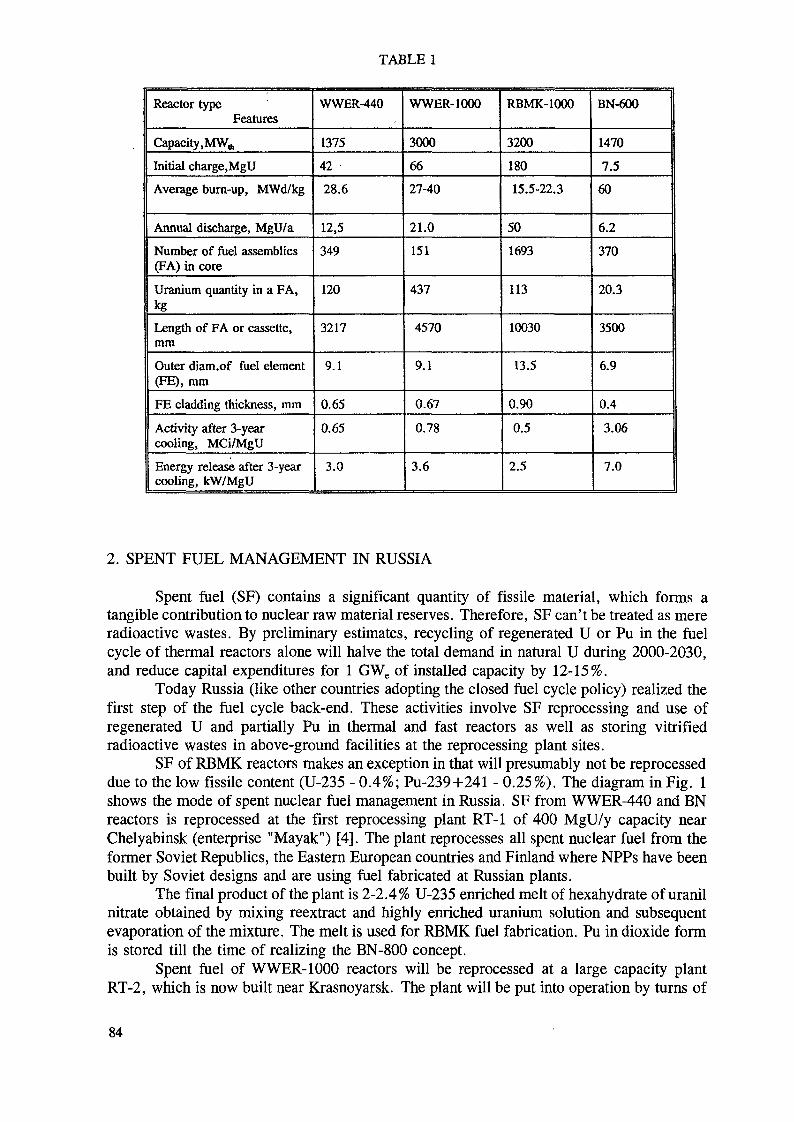
TABLE 1
Reactor typeFeatures
Capacity, MW,,,Initial charge.MgU
Average burn-up, MWd/kg
Annual discharge, MgU/aNumber of fuel assemblies(FA) in coreUranium quantity in a FA,kgLength of FA or cassette,mm
Outer diam.of fuel element(FE), mmFE cladding thickness, mm
Activity after 3-yearcooling, MCi/MgU
Energy release after 3-yearcooling, kW/MgU
WWER-440
1375
42
28.6
12,5349
120
3217
9.1
0.65
0.65
3.0
WWER-1000
3000
6627-40
21.0
151
437
4570
9.1
0.67
0.78
3.6
RBMK-1000
3200
180
15.5-22.3
501693
113
10030
13.5
0.90
0.5
2.5
BN-600
1470
7.5
60
6.2
370
20.3
3500
6.9
0.4
3.06
7.0
2. SPENT FUEL MANAGEMENT IN RUSSIA
Spent fuel (SF) contains a significant quantity of fissile material, which forms atangible contribution to nuclear raw material reserves. Therefore, SF can't be treated as mereradioactive wastes. By preliminary estimates, recycling of regenerated U or Pu in the fuelcycle of thermal reactors alone will halve the total demand in natural U during 2000-2030,and reduce capital expenditures for 1 GWe of installed capacity by 12-15%.
Today Russia (like other countries adopting the closed fuel cycle policy) realized thefirst step of the fuel cycle back-end. These activities involve SF reprocessing and use ofregenerated U and partially Pu in thermal and fast reactors as well as storing vitrifiedradioactive wastes in above-ground facilities at the reprocessing plant sites.
SF of RBMK reactors makes an exception in that will presumably not be reprocesseddue to the low fissile content (U-235 - 0.4%; Pu-239+241 - 0.25%). The diagram in Fig. 1shows the mode of spent nuclear fuel management in Russia. SF from WWER-440 and BNreactors is reprocessed at the first reprocessing plant RT-1 of 400 MgU/y capacity nearChelyabinsk (enterprise "Mayak") [4]. The plant reprocesses all spent nuclear fuel from theformer Soviet Republics, the Eastern European countries and Finland where NPPs have beenbuilt by Soviet designs and are using fuel fabricated at Russian plants.
The final product of the plant is 2-2.4% U-235 enriched melt of hexahydrate of uranilnitrate obtained by mixing reextract and highly enriched uranium solution and subsequentevaporation of the mixture. The melt is used for RBMK fuel fabrication. Pu in dioxide formis stored till the time of realizing the BN-800 concept.
Spent fuel of WWER-1000 reactors will be reprocessed at a large capacity plantRT-2, which is now built near Krasnoyarsk. The plant will be put into operation by turns of
84

Spentnuclear fuel
Iv V
WWER-44OWWER-1000
BN
lvRBMK-1000
no less 3-yearcooling atreactorfacilities
Intermediate sto-rage for 40 yearsI
Transportation toreprocessing plant
Transportation tofuel conditioningplant
vChemica1reprocessing
Fuel conditioning
Fabrication ofmixed U-Pu fuelelements
V V
Radioactive wasteconditioning Figefn
Final disposal ingeologicalformation
FIG. 1. Diagram of spent nuclear fuel management in Russia.
1500 MgU capacity each. The final product of the U-line is hexahydrate uranil nitrate meltused for uranium reenrichment and fuel element fabrication. The product of the Pu-line isuranium and plutonium dioxide mixture which will be used for WWER-1000 and BN-800fuel fabrication.
In view of the substantial uranium reserves in Russia, the expansion of reprocessingcapacities would not be economically attractive at least till 2005. Therefore, the nationalnuclear program during 1990-2000 with respect to fuel cycle back-end involves:
- the practice of reprocessing all spent fuel from the WWER and BN reactorsusing regenerated U for the fabrication of fresh nuclear fuel for RBMK reactors;storing regenerated Pu; vitrifying liquid high-level radioactive wastes; storingvitrified blocks at above-ground storage facilities of the reprocessing plants whichmeet all modern safety requirements;- as regards RBMK type fuel: long-term engineered storage at specializedfacilities at the reactor site; development of methods for direct final disposal;- safe engineered storage of WWER-1000 spent fuel in a specialized storagefacility at the site of the Krasnoyarsk reprocessing plant;- complete construction of RT-1 commercial plant for HLW-vitrification in viewof wastes volume reduction; development by 1995 of commercial industry withthe aim to recover long-lived radionuclides (during spent fuel reprocessing) andby this means to improve the safety and reliability of HLW managementtechnologies;- progressive (since 1993) putting into operation pilot plants for solid radioactivewaste conditioning;
85

ooON
14 12
IV1-body; 2-lid; 3-basket;4-VAVER-1000 PA(without a basket);5-neutron shield; 6-compenaatingtank; 7-device for filling neutronshield tank; 8-water dischargefrom cask inner cavity; 9-wateroverflow from cask inner cavity;10-freight trunnion; 11-caskfastening and manipulating trun-nion; 12-securing trunnion;13-flange for a lug; 14-plug;15-pin; 16-gasket; 17-mecb.anismfor gripping;.18-support ring;19-fixing claw; 20-wedge-shapeda top; 21-pres3ing mechanism;22-guide key; 23-hexahedral boronsteel pipe; 24-thermal converter,;25-circular groove.
FIG. 2. Transportation package TK-13/1.
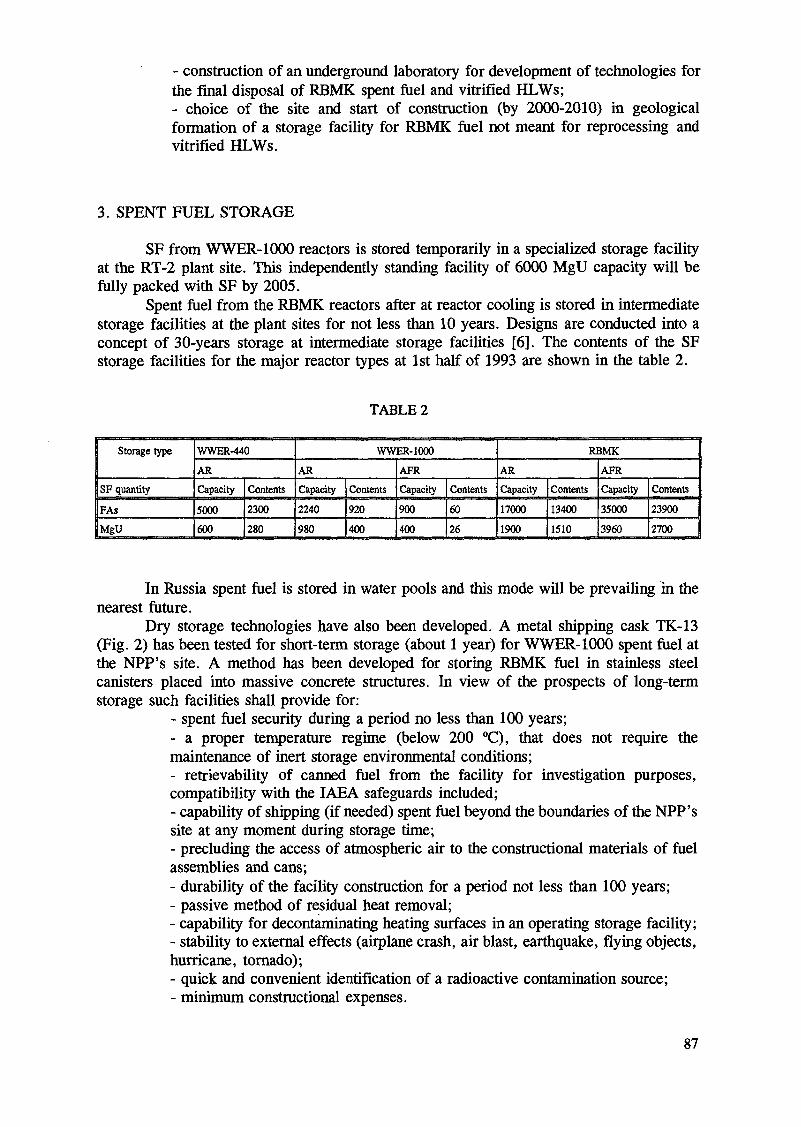
- construction of an underground laboratory for development of technologies forthe final disposal of RBMK spent fuel and vitrified HLWs;- choice of the site and start of construction (by 2000-2010) in geologicalformation of a storage facility for RBMK fuel not meant for reprocessing andvitrified HLWs.
3. SPENT FUEL STORAGE
SF from WWER-1000 reactors is stored temporarily in a specialized storage facilityat the RT-2 plant site. This independently standing facility of 6000 MgU capacity will befully packed with SF by 2005.
Spent fuel from the RBMK reactors after at reactor cooling is stored in intermediatestorage facilities at the plant sites for not less than 10 years. Designs are conducted into aconcept of 30-years storage at intermediate storage facilities [6]. The contents of the SFstorage facilities for the major reactor types at 1st half of 1993 are shown in the table 2.
TABLE 2
Storage type
SF quantity
FAsMgU
WWER-440
ARCapacity
5000600
Contents
2300
280
WWER-1000
ARCapacity2240
980
Contents920400
AFRCapacity900400
Contents6026
RBMK
ARCapacity170001900
Contents
13400
1510
AFRCapacity
35000
3960
Contents23900
2700
In Russia spent fuel is stored in water pools and this mode will be prevailing in thenearest future.
Dry storage technologies have also been developed. A metal shipping cask TK-13(Fig. 2) has been tested for short-term storage (about 1 year) for WWER-1000 spent fuel atthe NPP's site. A method has been developed for storing RBMK fuel in stainless steelcanisters placed into massive concrete structures. In view of the prospects of long-termstorage such facilities shall provide for:
- spent fuel security during a period no less than 100 years;- a proper temperature regime (below 200 °C), that does not require themaintenance of inert storage environmental conditions;- retrievability of canned fuel from the facility for investigation purposes,compatibility with the IAEA safeguards included;- capability of shipping (if needed) spent fuel beyond the boundaries of the NPP'ssite at any moment during storage time;- precluding the access of atmospheric air to the constructional materials of fuelassemblies and cans;- durability of the facility construction for a period not less than 100 years;- passive method of residual heat removal;- capability for decontaminating heating surfaces in an operating storage facility;- stability to external effects (airplane crash, air blast, earthquake, flying objects,hurricane, tornado);- quick and convenient identification of a radioactive contamination source;- minimum constructional expenses.
87
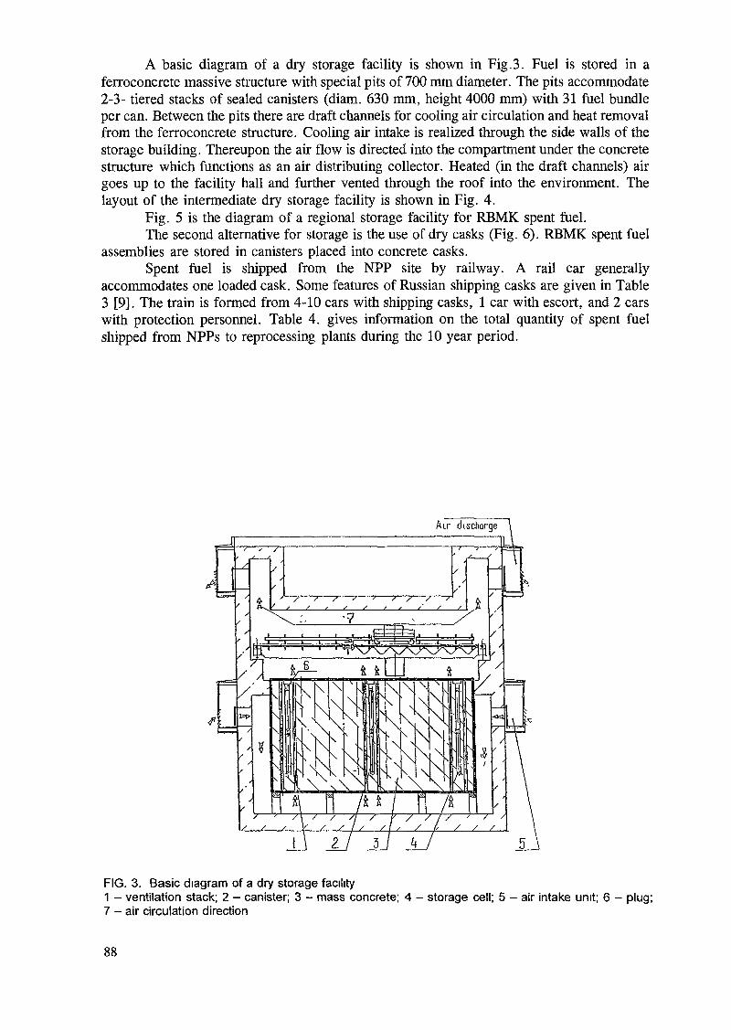
A basic diagram of a dry storage facility is shown in Fig.3. Fuel is stored in aferroconcrete massive structure with special pits of 700 mm diameter. The pits accommodate2-3- tiered stacks of sealed canisters (diam. 630 mm, height 4000 mm) with 31 fuel bundleper can. Between the pits there are draft channels for cooling air circulation and heat removalfrom the ferroconcrete structure. Cooling air intake is realized through the side walls of thestorage building. Thereupon the air flow is directed into the compartment under the concretestructure which functions as an air distributing collector. Heated (in the draft channels) airgoes up to the facility hall and further vented through the roof into the environment. Thelayout of the intermediate dry storage facility is shown in Fig. 4.
Fig. 5 is the diagram of a regional storage facility for RBMK spent fuel.The second alternative for storage is the use of dry casks (Fig. 6). RBMK spent fuel
assemblies are stored in canisters placed into concrete casks.Spent fuel is shipped from the NPP site by railway. A rail car generally
accommodates one loaded cask. Some features of Russian shipping casks are given in Table3 [9]. The train is formed from 4-10 cars with shipping casks, 1 car with escort, and 2 carswith protection personnel. Table 4. gives information on the total quantity of spent fuelshipped from NPPs to reprocessing plants during the 10 year period.
4<
FIG. 3. Basic diagram of a dry storage facility1 - ventilation stack; 2 — canister; 3 - mass concrete; 4 - storage cell; 5 - air intake unit; 6 - plug;7 - air circulation direction
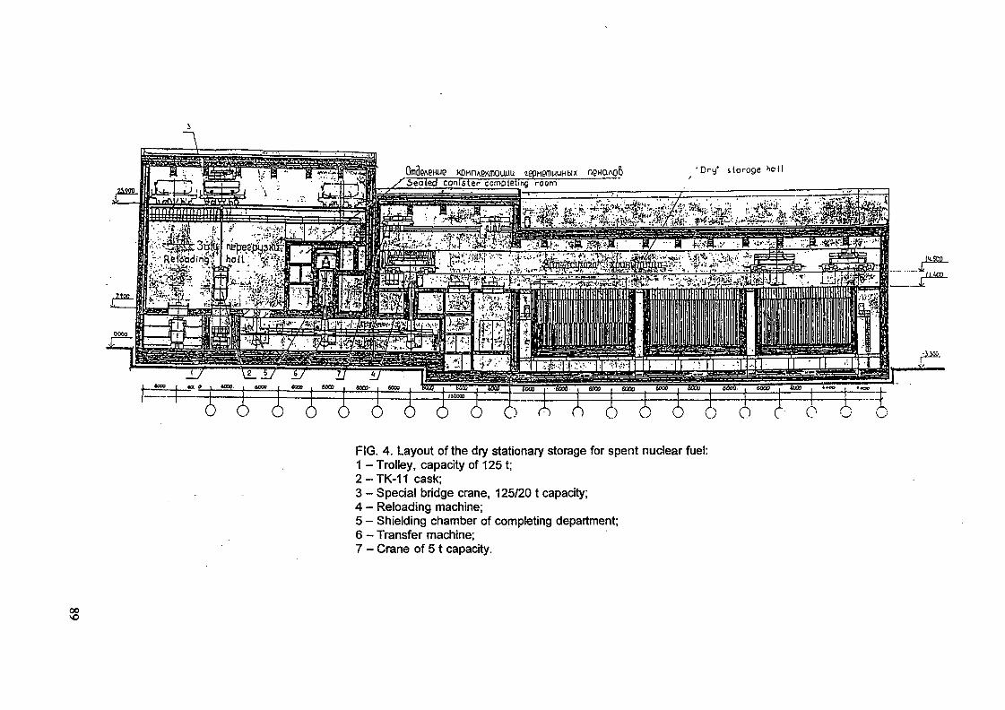
KOHnAexmauuu tepnemnuHbixX^Seoted canister completing room
FIG. 4. Layout of the dry stationary storage for spent nuclear fuel:1 -Trolley, capacity of 125 t;2-TK-11 cask;3 - Special bridge crane, 125/20 t capacity;4 - Reloading machine;5 - Shielding chamber of completing department;6 - Transfer machine;7 - Crane of 51 capacity.
oo
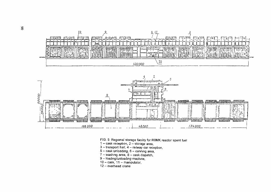
p» STR. r p* n F -:\ ra M' ' - •ÛZOLIJLUJJIL
. j
FIG. 5 Regronal storage facility for RBMK reactor spent fuel1 - cask reception, 2 - storage area,3 - transport hall, 4 - railway car reception,5 - cask unloading, 6 - canning area,7 - washing area, 8 - cask dispatch,9 - loading/unloading machine,10 - cask, 11 - manipulator,12 - overhead crane
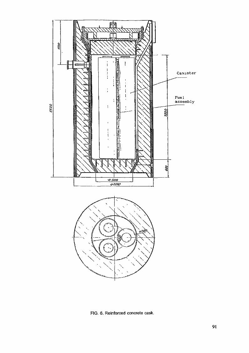
i •1 L
! , 11 , -; r
1 !. 'rJi h
l
i
!
! '
ii ;' i' T
I ^
\
'
,
-'r
11
• i
i iL
Fuelassembly
Canister
FIG. 6. Reinforced concrete cask.
91
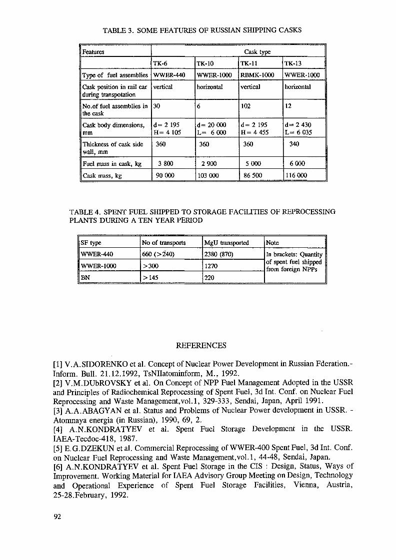
TABLE 3. SOME FEATURES OF RUSSIAN SHIPPING CASKS
Features
Type of fuel assembliesCask position in rail carduring transpotationNo.of fuel assemblies inthe caskCask body dimensions,mmThickness of cask sidewall, mmFuel mass in cask, kgCask mass, kg
Cask type
TK-6
WWER-440
vertical
30
d= 2 195H= 4 105360
380090000
TK-10
WWER-1000
horizontal
6
d= 20000L= 6000360
2900103000
TK-11
RBMK-1000
vertical
102
d= 2 195H= 4 455360
500086500
TK-13
WWER-1000
horizontal
12
d= 2 430L= 6 035
340
6000116000
TABLE 4. SPENT FUEL SHIPPED TO STORAGE FACILITIES OF REPROCESSINGPLANTS DURING A TEN YEAR PERIOD
SFtypeWWER-440
WWER-1000
BN
No of transports660 (>240)
>300
>145
MgU transported2380 (870)
1270
220
NoteIn brackets: Quantityof spent fuel shippedfrom foreign NPPs
REFERENCES
[1] V.A.SIDORENKO et al. Concept of Nuclear Power Development in Russian Fderation.-Inform. Bull. 21.12.1992, TsNIIatominform, M., 1992.[2] V.M.DUbROVSKY et al. On Concept of NPP Fuel Management Adopted in the USSRand Principles of Radiochemical Reprocessing of Spent Fuel, 3d Int. Conf. on Nuclear FuelReprocessing and Waste Management,vol.1, 329-333, Sendai, Japan, April 1991.[3] A. A.ABAGYAN et al. Status and Problems of Nuclear Power development in USSR. -Atomnaya energia (in Russian), 1990, 69, 2.[4] A.N.KONDRATYEV et al. Spent Fuel Storage Development in the USSR.IAEA-Tecdoc-418, 1987.[5] E.G.DZEKUN et al. Commercial Reprocessing of WWER-400 Spent Fuel, 3d Int. Conf.on Nuclear Fuel Reprocessing and Waste Management,vol.1, 44-48, Sendai, Japan.[6] A.N.KONDRATYEV et al. Spent Fuel Storage in the CIS : Design, Status, Ways ofImprovement. Working Material for IAEA Advisory Group Meeting on Design, Technologyand Operational Experience of Spent Fuel Storage Facilities, Vienna, Austria,25-28.February, 1992.
92
[7] F.N.KONDRATYEV, YU.V.KOZLOV, T.F.MAKARCHUK, N.S.TIKHONOV, NPPSpent Fuel Storage Experience, Research Trends on Different Aspects of Storage Problem.Seminar of CMEA Specialists on Spent Fuel Problem, 8-12 October 1990, Rzez, CSFR.[8] Construction of Spent Fuel Storage Facility at Ignalina NPP site - Feasibility Study. VOVNIPIET, St.-Petersburg, 1992.[9] A.N.KONDRATYEV, YU.A.KOSAREV, N.S.TIKHONOV, Spent Nuclear Fuel Storageand Transportation in the USSR, 3d Int. Conf. on Nuclear Fuel Reprocessing and WasteManagement,vol.1, 378-382, Sendai, Japan, April 1991.
Next page(s) left blank 93

SPENT FUEL MANAGEMENT IN THE SLOVAK REPUBLIC
J. KMOSENANuclear Power Plant Bohunice,Jaslovske Bohunice, Slovak Republic
Abstract
More than 55% of the electricity generated in Slovakia is produced by 4 commercial reactors (VVER-440 type) located at the Bohunice site. Approximately 4500 spent assemblies were produced during the past 12years of operation. Spent fuel is stored in at-reactor pools and in an on-site wet intermediate storage. A smallparty about 17% of spent fuel was shipped to the former Soviet Union. Part of the spent fuel, produced inDukovany NPP (Czech Rep.) is temporary stored in interim storage. The stages of fuel management and futureplans for Slovakia are described. A special problem is the storage of a small amount (132) of seriously damagedassemblies from the A-l HWGCR, operated in Bohunice in the period of 1971-1977; that fuel is hi the at-reactor pool. The final project to solve this problem is described.
1. NUCLEAR POWER PLANTS IN SLOVAKIA
The nuclear power plants of the Slovak Republic are at two locations:a) at Jaslovske Bohunice site:
2 units WER 440, older V 230 type,2 units WER 440, V 213 type,1 HWGCR unit Al, in decommissioning stage.
b) at Mochovce site:4 units WER 440, V 213 type
Comment: All energy sources - fossile, hydro and nuclear - areconcentrated in the Company Slovak Energetic Enterprises - SEP.
2. BASIC DATA ON NUCLEAR POWER PLANTS (Fig. 1.)
2.1. Jaslovske Bohunice site
a) The Demonstration Heavy water moderated, gas cooled reactor, Al, operated fromOctober 1972 up to February 1977. A complicated decommissioning process is going on.
b) At present time there are 4 WER 440 units hi operation;start - up data: unit 1 - December 1978
unit 2 - March 1980unit 3 - August 1984unit 4 - August 1985
Nuclear Power PlantsSlovak Republic (SEP)
PlantBohunice A1
Bohunice "1&2Bohunice 3&4
Mochovce 1 - 4
Net Capacity1 x 1502x4082x4084x408
ModelHWGCR
230213213
Commercial Operation1972-77 (Demonstr.)
1978, 19801984,1985
FIG. 1.
95
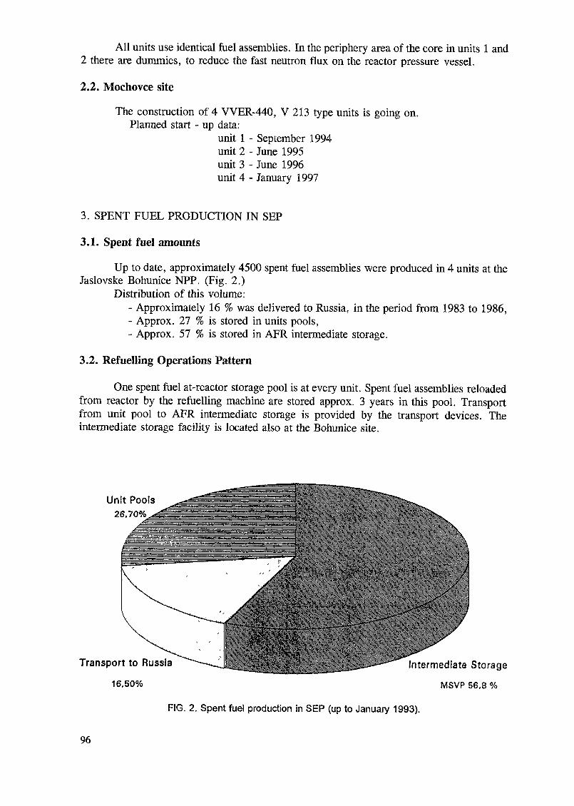
All units use identical fuel assemblies. In the periphery area of the core in units 1 and2 there are dummies, to reduce the fast neutron flux on the reactor pressure vessel.
2.2. Mochovce site
The construction of 4 VVER-440, V 213 type units is going on.Planned start - up data:
unit 1 - September 1994unit 2 - June 1995unit 3 - June 1996unit 4 - January 1997
3. SPENT FUEL PRODUCTION IN SEP
3.1. Spent fuel amounts
Up to date, approximately 4500 spent fuel assemblies were produced in 4 units at theJaslovske Bohunice NPP. (Fig. 2.)
Distribution of this volume:- Approximately 16 % was delivered to Russia, in the period from 1983 to 1986,- Approx. 27 % is stored in units pools,- Approx. 57 % is stored in AFR intermediate storage.
3.2. Refuelling Operations Pattern
One spent fuel at-reactor storage pool is at every unit. Spent fuel assemblies reloadedfrom reactor by the refuelling machine are stored approx. 3 years in this pool. Transportfrom unit pool to AFR intermediate storage is provided by the transport devices. Theintermediate storage facility is located also at the Bohunice site.
Unit Pools26,70%
Transport to Russia
16,50%
Intermediate Storage
MSVP 56,8 %
FIG. 2. Spent fuel production in SEP (up to January 1993).
96

Refuell. I1 Machine I
X
\\\\\\
\
X̂X
/ —
s _
— \
— /
^;'/X
4.
XvüüClvc IxcLUiA.
Basic RackL.. . . . . ................. .........
XSXX
v/\•1
Unit pool ,
Fuel: Hexaqonal 144mm, L = 3200 mm, 120 kg U
Assemblies in unit:EBO 1,2 ( V I )EBO 3,4 (V2)EMO 1,2.3,4
reactor R313349349
basic rack350350700
reserve rack350350350
FIG. 3. Unit pool characteristics V 230 type.
3.3. Unit pool characteristics
The capacity of every unit pool is approx. 350 fuel assemblies. Fuel is stored in"basic racks". It is possible to place in the pool the "reserve racks". It is done, if the totalcore evacuation is needed in emergency situation, or during unit outage and fuel reload.(Fig. 3.)
The storage pools at the reactors of the Mochovce NPP will be compacted. This factallows NPP Mochovce to store the spent fuel for a 6 year period. By the start-up timeschedule of Mochovce, there are no problems with spent fuel storage till the end of 2001.
4. TRANSPORT DEVICES
The basic transport devices are:- transport cask, for 30 fuel assemblies,- transport shielding container,- railroad wagon.
This transport group provides the transport between Bohunice units, AFR intermediatestorage at Bohunice, Dukovany NPP and (in the past) Russia.
5. BASIC DATA ON INTERMEDIATE STORAGE
Operation:Storage type:
from January 1987wet, pool type4 pools - 3 operating
- 1 reservestoring 30 fuel assemblies in one basket
97
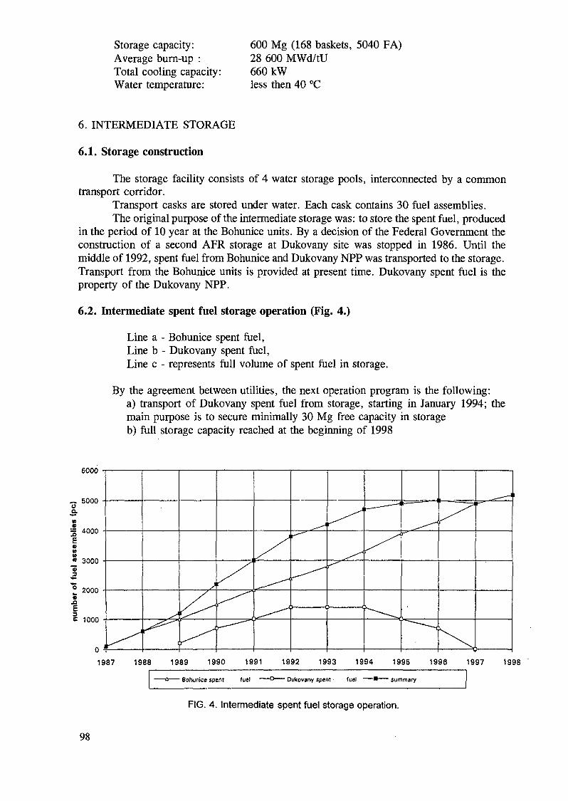
Storage capacity:Average burn-up :Total cooling capacity:Water temperature:
600 Mg (168 baskets, 5040 FA)28 600 MWd/tU660 kWless then 40 °C
6. INTERMEDIATE STORAGE
6.1. Storage construction
The storage facility consists of 4 water storage pools, interconnected by a commontransport corridor.
Transport casks are stored under water. Each cask contains 30 fuel assemblies.The original purpose of the intermediate storage was: to store the spent fuel, produced
in the period of 10 year at the Bohunice units. By a decision of the Federal Government theconstruction of a second APR storage at Dukovany site was stopped in 1986. Until themiddle of 1992, spent fuel from Bohunice and Dukovany NPP was transported to the storage.Transport from the Bohunice units is provided at present time. Dukovany spent fuel is theproperty of the Dukovany NPP.
6.2. Intermediate spent fuel storage operation (Fig. 4.)
Line a - Bohunice spent fuel,Line b - Dukovany spent fuel,Line c - represents full volume of spent fuel in storage.
By the agreement between utilities, the next operation program is the following:a) transport of Dukovany spent fuel from storage, starting in January 1994; themain purpose is to secure minimally 30 Mg free capacity in storageb) full storage capacity reached at the beginning of 1998
6000
1987 1988 1989 1990 1991 1992 1993 1994 1995 1996 1997 1998—— û —— Bohunice spent fuel — -° —— Dukovany spent fuel — • —— summary
FIG. 4. Intermediate spent fuel storage operation.
98

SEP will increase the storage capacity for spent fuel till the end of 1997 at the latest.The final decision, whether there will be an independent storage for each NPP or onecommon facility for both plants, will be done at the end of 1993. This new capacity mustalso fulfill the technical requirements for the new type of fuel.
At present the average fuel assembly burnup is 32.000 MWd/tU and the maximumenrichment is 3.6%. It is expected that the new fuel can reach higher burnup in the range of40-45 000 MWd/tU.
7. TIME SCHEDULE FOR THE FINAL DISPOSAL OF SPENT FUEL
Several preliminary geological studies were carried out to provide a basis for startingup the preparatory works. These works were oriented to find the best solution for the finalrepository at the Slovak territory, to place the spent nuclear fuel.
The State Energy Policy Programme assumes to build up the final repository of spentfuel with State guarantee. It is expected to establish close cooperation with foreign partners,who have a long experience in developing concepts for the direct disposal of spent fuel. Itis supposed to start up of the final disposal approximately hi 2030. (Fig. 5.)
Research.prellmlnerystudies, geologicalinvestigationsLocality decision
Design elaboration
Disposal construction
Operation
*mmiiiiiiiiMii
iiiimmim
1990 2000 2010 2020 2030 2040
FIG. 5. Disposal of spent fuel - time schedule.
8. A-l SPENT FUEL - SPECIFIC PROBLEM
According to the agreement between former CSSR and USSR, all the A-l spent fuel(Fig. 6.) should be transported to the USSR reprocessing facilities.
As a result of changes in both countries and as a result of technical problems, 132damaged spent fuel assemblies are in the A-l spent fuel pool at present. A sophisticatedsolution of this new problem does not exist yet.
99

Individual Container
Fuel Raaembly
2—5 * solution
and
1-
, _fl___ _IAIto
4*9-1
S?o•i
Spent Fuel Pool
_s_
^ X y / ^ x / / / / y / x xx-TT1/
FIG. 6. A1 fuel.
The proposed solution:- to evaluate the possibility of short-term storage of assemblies in wet conditions,- to prepare a conditioning technology for the transport to the reprocessing facility(or to the final disposal),- reprocessing, transport of high-level wastes to final repository.
An optimal solution of this specific problem is evaluated at present.
100

SWEDISH SPENT FUEL MANAGEMENT; SYSTEMS,FACILITIES AND OPERATING EXPERIENCES
J. VOGTSwedish Nuclear Fuel and Waste Management Company,Stockholm, Sweden
Abstract
About 50% of the electricity in Sweden is generated by means of nuclear power from 12 LWR reactorslocated at four sites and with a total capacity of 10 000 MW. The four utilities have jointly created 8KB, theSwedish Nuclear Fuel and Waste Management Company, which has been given the mandate to manage the spentfuel and radioactive waste from its origin at the reactors to the final disposal. 8KB has developed a system forthe safe handling of all kinds of radioactive waste from the Swedish nuclear power plants. The keystones nowin operation of this system are: a transport system; a central interim storage facility for spent nuclear fuel,CLAB; and a final repository for short-lived, low and intermediate level waste, SFR. The remaining systemcomponents being planned are: an encapsulation plant for spent nuclear fuel; a deep repository for encapsulatedspent fuel and other long-lived radioactive wastes. The paper describes the transport system and CLAB andexperiences gained during several years of operation. The paper also deals with the ongoing activities and plansconcerning the encapsulation plant and the final repository.
1. INTRODUCTION
About 50% of the electricity in Sweden is generated by means of nuclear power from12 reactors located at four sites and with a total capacity of 10 000 MW. Nine of the reactorsare BWRs and three PWRs. The first commercial reactor was put in operation hi 1972 andthe latest in 1985. According to a decision by the Swedish Parliament all reactors shall bephased out by the year 2010 at the latest. Until then about 8000 Mg of fuel will have beenused and will have to be taken care of as spent nuclear fuel. Today the total fuel quantityamounts to about 3500 Mg including the fuel in the reactor cores.
According to the Swedish spent fuel management program the fuel from the Swedishreactors shall be taken care of within the country and be disposed of at about 500 metresdepth in the bedrock.
After unloading from the reactor core and a cooling period at the reactors the spentfuel is transported to a central interim storage facility where the fuel will remain for 30 - 40years. During this period the radioactivity and the residual heat of the fuel will decay byabout a factor often, thus making further handling and the final disposal simpler. The storageperiod will also provide tune and flexibility for the elaboration of the details of these steps.
The responsibility for the management of the spent nuclear fuel, as well as for otherradioactive residues from nuclear power production, lies with the operators of the nuclearpower plants, ie the four nuclear utilities. The utilities have jointly created SKB, the SwedishNuclear Fuel and Waste Management Company, which has been given the mandate to safelymanage the spent fuel and radioactive waste from its origin at the reactors to the finaldisposal. The task of SKB is thus to plan, construct, own and operate the systems and facili-ties necessary for transportation, interim storage and final disposal.
101

CLAB, Central interimstorage facility for spentnuclear fuel.Start ofoperation1985.
SFR, Final repositoryfor radioactiveoperational waste.Start of operation1988.
Deep geological repository for«pent nuclear fuel. Planneddemonstration deposition 2008a! earliest.
FIG. 1. The Swedish system for radioactive waste management.
2. SYSTEMS AND FACILITIES
8KB has developed a system that ensures the safe handling of all kinds of radioactivewaste from the Swedish nuclear power plants for a long time period ahead. The keystonesof this system are (Fig 1):
- A transport system which has been in operation since 1983.- A central interim storage facility for spent nuclear fuel, CLAB, in operation
since 1985.- A final repository for short-lived, low and intermediate level waste, SFR, in
operation since 1988.The remaining system components now being planned are:
- An encapsulation plant for spent nuclear fuel, and- A deep disposal facility for encapsulated spent fuel and other long-lived
radioactive wastes.This paper deals with the existing and future facilities for the management of spent
nuclear fuel.
3. THE TRANSPORT SYSTEM
As all the nuclear power plants and CLAB are located on the coast and have their ownharbours SKB has developed a sea transport system. This has many advantages, such as ahigh load capacity and low interference with other traffic. The system comprises a ship, theM/S Sigyn, 10 transport casks for spent fuel, 2 casks for spent core components and 5terminal vehicles. The latter are used for the land transport from the reactor to the harbourand from the harbour to CLAB.
The M/S Sigyn is a roll on/roll off, lift on/lift off ship, purpose built for transportsof radioactive waste. She has a dead-weight of 2000 Mg and can carry up to 10 spent fueltransport casks. She has been designed with the most restrictive IMO rules concerningfloatability after damage, similar to those for ships carrying chemicals in bulk. Theicebreaking capability of the ship increases the availability in winter conditions. Anotherimportant safety factor is the most modem navigation equipment installed on board. Howeverthe ultimate safety of the transports depends on the 80 Mg heavy transport casks designedaccording to the IAEA regulations.
102

The dry nitrogen filled cask cavity can accommodate 17 BWR or 7 PWR assembliescorresponding to 3 Mg of fuel. The cask is cooled by natural air convection around the40 000 cooling fins on the cask outer surface. The cooling capacity allows fuel with a burnupof 55 000 MWd/tU and 6 months cooling time to be transported.
The dose rate criteria given by the transport regulations are, however, more limitingthan the thermal ones, mainly due to the buildup of neutron emitters at high burnups.Transport of fuel assemblies with a burnup of 43 000 MWd/tU requires a cooling time ofminimum 20 months.
Higher burnups will soon be reached requiring even much longer cooling times.Therefore a modification of the cask is planned involving an increase of the thickness of theneutron absorbing resin on the cask surface.
Operating experiences
By the end of 1992 almost 600 fuel transport casks have been shipped to CLAB,corresponding to about 1700 Mg of uranium. In parallel around 50 casks with highly activecore components, eg control rods, have been shipped to CLAB. Typically 75 fuel casks aretransported annually, corresponding to about 225 Mg of fuel.
The performance and availability of the system has been excellent. The fast andefficient handling and lashing operations for the casks on the ship have resulted in crew dosesclose to the those coming from the background radiation.
Another factor contributing to the good results is the detailed cask maintenanceprogramme according to which a cask is brought in for maintenance after 15 transport cycles.Each transport cask has already gone through 4 to 5 such overhauls. A more extensive main-tenance is made after 60 cycles.
The transport system is also used for transport of low and intermediate level waste tothe SFR facility.
When M/S Sigyn is idle she is also used occasionally for conventional heavy transportson a commercial basis.
During the last summers M/S Sigyn has been used as a floating exhibition for informa-tion to the public about the Swedish nuclear waste management system. In total almost300 000 persons have visited the exhibition.
4. CENTRAL INTERIM STORAGE FOR SPENT FUEL, CLAB
CLAB, the central interim storage facility for spent nuclear fuel, is located close tothe Oskarshamn nuclear power plant on the Swedish east coast.
CLAB consists of two principal parts, one above ground and one under ground.(Fig. 2.) The main complex above ground is the receiving building, where the transport casksare received, prepared and unloaded. The unloading is performed under water. The storagesection is located below ground in a rock cavern, the roof of which is 25-30 metres belowthe surface.
Interconnected with the receiving building are buildings for auxiliary systems, eg forwater cooling and purification, and for the electric power and control system.
The receiving building has three receiving pool lines, two of which are speciallyequipped for the standard TN17/2 transport casks. The third line can receive non-standardcasks. Prior to unloading the cask is provided with a metal skirt for protection against outsidecontamination and damage, tested for fuel leakage, and cooled. The cask is then transferredto the receiving pool, where the lid is removed so that the fuel assemblies can be lifted outone by one. Unloading - and all subsequent handling of the fuel assemblies - is performed
103

l. Receiving building3. Offices5. Fuel elevator
2. Auxiliary systems4. Electrical building6. Storage cavern
FIG. 2. CLAB, Central interim storage facility for spent fuel.
underwater with hydraulic handling machines. The pools are arranged in such a way that theouter surface of the cask is in contact with non-contaminated water, while the fuel assembliesand the internals of the cask are in contact with contaminated water. In the receiving pool thefuel assemblies are transferred from the transport cask to a storage canister, which is thenused as the handling unit.
The underground storage section consists of 4 storage pools in a 120 metre long rockcavern. Each pool contains about 3000 m3 of water and can hold 300 storage canisters. Whenplaced in the storage pools the canisters serve as storage racks. A fifth pool in the cavern isused for transfer of canisters and as a reserve in case of problems with one of the storagepools. The canisters are brought down to the rock cavern by means of the fuel elevator.During transfer from the pools in the receiving building to the elevator shaft the canister inits water filled cage passes through a water trap. The elevator shaft itself is not water-filled.
The canisters are designed to maintain an adequate margin against criticality undernormal and accident conditions. The original storage canisters can hold 16 BWR or 5 PWRfuel assemblies and have an internal structure made of normal stainless steel. Recently thecanister capacity has been increased to 25 BWR or 9 PWR fuel assemblies, thereby enlargingthe total storage capacity of CLAB from 3000 Mg of uranium to 5000 Mg. Two alternativeswere considered to achieve this and at the same time to maintain a sufficient reactivitymargin:
- the use of canisters with internal neutron absorbers, i. e. borated steel or- credit for burnup.
After a thorough analysis the boron option was chosen. This has the advantage thatthe control of the fuel assemblies at reception can be made much easier as it allows fresh fuelelements to be stored.
In the case with credit for burn up rather complicated verification measurements onthe fuel assemblies at reception would have been necessary. It was further found thatunexpectedly great uncertainties were coupled to the BWR fuel assemblies due to their axial
104

burnup profile and void history. In order to cover all possible cases it would therefore havebeen necessary to apply a great reactivity penalty in the licensing calculations. Under theseconditions it would not have been possible to store many of the already existing assembliesin the new canisters.
Other methods to increase the storage capacity were studied, eg new fixed storageracks, two tier storage and rod consolidation. These were not adopted due to higher costs orfor other technical reasons.
CLAB was put hi operation in 1985, and in december 1992 some 1700 Mg of fuel inabout 600 casks had been received in addition to about 50 casks with activated corecomponents, eg control rods.
The present capacity of CLAB of about 5000 Mg of uranium covers the needs untilaround year 2004. The Swedish nuclear program is expected to generate a total amount ofalmost 8000 Mg. CLAB must therefore be expanded by adding storage pools in a new rockcavern close to and parallel to the existing one. This was known already during the construc-tion of the facility and certain preparations were made to facilitate the building and theconnection of the new cavern to the existing fuel containing pools.
Operating experiences
The performance of the plant has been excellent and due to improvements theoperating costs have successively been reduced by about 30% between 1986 and 1992. Somefactors contributing to this reduction are improved operating procedures that have made itpossible to unload casks in one shift instead of two and to share the staff with the co-locatedreactors. A great saving was made possible by the installation of a heat recovery systemallowing the residual power from the fuel in the storage pools to be used to heat the entireplant.
The activity release from the fuel has been much lower than anticipated. During thedesign phase, based on foreign experience, a high crud release was expected when the fuelis exposed to a certain thermal shock when the dry cask is filled with water. The experienceat CLAB is, however, much better, which may to a great extent be attributed to the goodwater chemistry and the materials used in the Swedish reactors. The activity release from thefuel in the pools is also low and dominated by ionic Co-60 from the crud. This release is sen-sitive to temperature and is being kept down by a low pool water temperature.
The low activity release in combination with an optimized management of the used fil-ter resins has reduced the number of waste packages emanating from CLAB. The actualvolumes are at least five times lower than expected. Also the releases to the environment viawater or air have been very low, less than a factor 1000 below the permissible limits.
The annual collective radiation dose to the staff and contractors has been between 65and 135 mmanSv, which is about 25 - 50% of the dose originally calculated in the final safetyreport. The main part of the dose comes from the handling, preparation and maintenance ofthe transport casks. During the last years increased doses have also been due to themodification work that has been undertaken to adapt the handling equipment to the newcanisters.
Normally the fuel from the Swedish reactors is transported to CLAB in the standardTN17/2 cask and handled in a routine way at arrival. Occasionally some non-standard caskshave been received, eg with fuel from the old Swedish PHWR reactor at Âgesta and oldMOX fuel from some German nuclear power plants. The latter as a result of an exchange ofa small amount of fuel between Sweden and Germany. Also encapsulated residues from PostIrradiation Examination of LWR fuel at the Studsvik research centre are being shipped toCLAB in a special cask. All these non-standard casks have been received in the thirdunloading pool without any problems.
105

Encapsulation plant
The spent fuel will remain in CLAB for 30-40 years prior to encapsulation in a cor-rosion resistant canister and final disposal. The encapsulation plant is planned to be builtadjacent to CLAB as a direct extension of the facility. A design project for the plant hasstarted, aiming at a preliminary safety report and an environmental impact statement reportat the end of 1996. These documents will serve as a basis for an application for a permit tobuild the plant. The "hot" operation is planned to commence around year 2007. The expectedconstruction cost for the facility is around 2 billion SEK (appr. 300 MUSD). The work willproceed in parallel with the work on extending the storage capacity in CLAB by additionalpools.
The function of the canister is to provide adequate enclosure and radiation shieldingof the fuel during handling before disposal and then to provide an absolute barrier againstradioactivity release for very long time after disposal. To remain tight the canister mustsustain the mechanical and chemical environment in the repository.
The canister material most thoroughly studied in Sweden is copper which is almostunaffected in the reducing ground water found in the granitic bedrock. The expected lifetimefor a thick copper canister in such environment is millions of years and would thus isolatethe fuel even beyond the lifetime of Pu-239.
In cooperation with the Finnish power company TVO a composite canister has beendeveloped. (Fig. 3.) It consists of an inner steel canister that will take the mechanical loadand an outer copper canister that provides the corrosion protection. In comparison with earlier
Conister surface ( m2) 14.65Remaining infernal void ( m M 1,22Estimated weight IhglCopper canisterSteel canisterCanister weightFuel assemblies'Filling
616048001096036401800
Total 16400
FIG. 3. Copper/steel composite canister.
106
designs with a massive copper canisters fabricated by hot isostatic pressing technique or athick copper canister backfilled with lead, the new design has the advantage that the loadingof the fuel and the closing of the inner canister can be made at low temperature. Analysesshow that the new canister could provide the same isolation lifetime at a lower cost and asimpler fabrication technique.
The canister will contain 12 BWR or 4 PWR fuel assemblies. The amount of fuel thatcan be loaded into the canister is limited by the maximum permissible temperature of thecanister surface after disposal. This means that there is no advantage in consolidating the fuelassemblies. The outer diameter of the canister will be 880 mm, the height 4890 mm and thetotal weight about 16 Mg. For handling and transport an extra radiation shielding will beneeded.
The encapsulation plant is planned to be built directly wall to wall with CLAB. It willhave the following functions:
- Reception of canisters from CLAB via the existing fuel elevator- Checking of the fuel and drying.- Filling of the canister with fuel and optionally with an inert filling material.- Closing of the inner steel canister.- Welding of the copper canister lid and control of the weld.- Decontamination of filled canisters.- Buffer storage of filled canisters.- Loading of canisters in transport casks for transport to the repository.
In addition to this, service facilities such as auxiliary systems, and control andpersonnel facilities are required. Great advantage can be achieved by utilizing the existingcorresponding systems etc in CLAB. A flexibility will be built in into the plant as apreparation for a later treatment of activated core components that are going to be disposedof in a deep repository as well.
A crucial function in the encapsulation plant is the welding of the lid of the coppercanister. This must be done remotely with a high accuracy, and in such a way that the resultcan afterwards be checked by non destructive testing. Different alternatives are being investi-gated. The alternative preferred at present is electron beam welding at reduced atmosphericpressure.
The filled canister must have a sufficient margin to criticality. Under normalconditions when the canister is dry this is not a problem. For certain accident scenarios,however, it can be postulated that the canister will be water filled. If all the fuel assemblieshi the canister are assumed to be fresh a critical configuration will exist. It will thus benecessary to take credit for the burnup of the fuel, and/or to insert a neutron absorbingmaterial in the canister. As part of the checking of the fuel assemblies before placement inthe canister it is therefore expected that a detailed burnup measurement will be made. Thismeasurement may also be utilized for the safeguards verification that will be necessary beforethe closing of the canister.
5. FINAL DISPOSAL IN A REPOSITORY
The purpose of final disposal is to isolate the spent fuel in such a way that itsradioactivity will not reach the environment in harmful concentrations. This is proposed tobe done by encapsulating the spent fuel in a long-lived, corrosion resistant canister asdescribed above and by disposing the canister deep down hi the Swedish bedrock. For thepurpose of mechanical and chemical protection of the canister it will be surrounded by abuffer layer of compacted bentonite. (Fig. 4.) With this disposal concept, that is based on themulti-barrier principle, an absolute isolation of the spent fuel is expected for a very long time.
107

Disposal runnel with backfill
Compacted bentonite blocks
Composite Canister
FIG. 4. Arrangements in the deep repository.
The disposal will be made at about 500 metres depth. The canisters are deposited inholes drilled from the floors of drifts at a centre to centre distance of about 6 metres. In theholes the canisters are surrounded by highly compacted bentonite which acts as a mechanicaland chemical buffer material and prevents direct contact between flowing water and thecanister. The tunnels and shafts are backfilled with a mixture of sand and bentonite.
The siting of a deep repository is politically sensitive in Sweden as in many othercountries. From a technical point of view investigations have shown that there are many areasin Sweden were suitable geological conditions exist for a repository. Other factors such astransports, infrastructure, employment situation and political aspects will also be importantfor the siting.
To facilitate the siting and the public acceptance the disposal will be made stepwise.The first step will be the building the deep repository for a limited amount of spent fuel asa demonstration. When the demonstration deposition has been completed, the results will beevaluated before a decision is made whether or not to expand the facility to accommodate thetotal waste amount. This plan also makes it possible to consider whether the deposited fuelshould be retrieved for alternative treatment. This procedure will make it possible to dem-onstrate the siting, licensing, design and construction, handling of the canisters and operationof the facility. For obvious reasons the long-term safety of the repository cannot bedemonstrated. This must always be based on a technical-scientific assessment.
The start of the demonstration deposition could start at the earliest in the latter partof the next decade. Studies of the local conditions are planned to be started shortly in someareas in cooperation with the local authorities. If the conditions are found suitable detailedsite investigations will then be made at one site.
6. COSTS
The major parts of the costs for the spent fuel management will be incurred in thefuture. To ascertain that means will be available fees are levied on the nuclear electricityproduction and collected in state-controlled funds.
The costs are calculated annually and reported to the Government. In the price levelof 1992 the calculated cost for spent fuel management alone are on an average 4800 SEK/kgU (650 USD/kgU). The marginal cost for an additional quantity is 2200 SEK/kg U (300USD/kg U). All costs are not discounted. The relative distribution of these costs are:
TransportationInterim storage
4 %28 %
108

Encapsulation 27 %Final disposal 26 %Research and development 15 %
The costs for R&D also include all costs for finding and characterising the repositorysite.
REFERENCES
[1] P. DYBECK, B. GUSTAFSSON, "A Decade of Successful Domestic Sea Transportsof Radioactive Waste in Sweden 1982-1992", PATRAM 92 Int. Conf. YokohamaCity, Japan, September 1992.
[2] J. VOGT, B. GUSTAFSSON, "Experiences of Design and Operation of the SwedishCentral Storage Facility for Spent Fuel, CLAB," 8th Pacific Basin NuclearConference, Taipei, April 1992.
[3] SKB, "PASS - Projekt AlternativStudier for Slutförvar, Slutrapport", SKB,Stockholm, October 1992 (in Swedish).
[4] SKB, " Treatment and Final Disposal of Radioactive Wastes. Programme for Research,Development, Demonstration and other Measures. RD&D-Programme 92", SKB,Stockholm, September 1992.
[5] SKB, "PLAN 92. Costs for Management of the Radioactive Waste from NuclearPower Production", SKB TR 92-24, SKB, Stockholm, June 1992.
Next page(s) left blank 109
SPENT FUEL MANAGEMENT IN SWITZERLAND
C. OSPINAPaul Scherrer Institute,Villigen/Wurenlingen, Switzerland
Abstract
Switzerland currently has 3000 MWe being delivered from five nuclear power reactors. The currentspent fuel management and waste disposal programme includes reprocessing contracts for spent fuel andextension options. The status of a centralized intermediate store - ZWILAG - for spent fuel, high-level wasteand low/medium level wastes from nuclear power reactors is shown and the main features of the facilities underplanning are summarized. The Interim store for Federal Radwastes (BZL) started operation in November 1992,after only one and half years of construction. Noticeable progress has been achieved in the development of afinal repository for low and intermediate nuclear waste.
1. THE NUCLEAR PROGRAMME AND THE RADWASTE MANAGEMENT
Nuclear power was introduced already 24 years ago in Switzerland and today, fivenuclear power reactors are in use with a total capacity of about 3000 MWe (net) and achievea lifetime load factor of 83%; the nuclear share in the overall electricity production reachesnearly 41%.
The final waste disposal programme considers, for planning purposes, a nuclearinstalled capacity or 3000 MWe in the year 2000; assuming 40 years of plant operation foreach nuclear power unit, and taking into account the sources from reprocessing, the wasteswill amount to about 500 m3 of high level, 15,000 m3 medium level and 120,000 m3 of lowlevel types. Legal regulations require the permanent and safe disposal of all of these wastesin final repositories.
Appropriate research and development is carried out by NAGRA (National Co-operative for the Storage of Radioactive Waste), in order to demonstrate the final disposal ofradwaste. The 1985 Project GEWÄHR (PG'85) showed the technical feasibility of therepositories, and allowed NAGRA to adapt its disposal concept; the following importantpoints are the basis of the actual disposal concepts:
- The radwaste final disposal program is very important and is being stronglysupported; nevertheless it is required to build an interim store for the radwastesresulting from the reprocessing contracts; this facility should be in operation in themid - of nineties.- The disposal of short-lived low- and intermediate waste is currently feasible andwork in this field has top priority; four potential sites have been investigated:Oberbauenstock, Piz Pian Grand and Wellenberg (already finished); at Boi de laGlaive, the field-work started in 1990 and meanwhile its nearly finished; the drillingdepth at these sites varied from 306 m up to 1,703 m.- NAGRA, in mid 1993, proposed to the Federal Government, the Wellenberg site asa final repository for low- and intermediate waste; this site offers clear advantages:with respect to proven geological long-term safety, good environmental development,a large and compact marl formation and sound transportation facilities. Meanwhile thefinal studies and field results are being documented, in order to apply in 1994 for itslicensing which will allow construction start by the end of the nineties.
I l l
- Open questions relate primarily to identification of a site for disposal of high-levelwaste - HLW; work in this respect is very significant but is of secondary importancefrom the point of view of timing (required in year 2020); seven deep drillings (1,000 -2,500 m) have been done in crystalline formations and new geophysical work was
finished in 1992 to investigate the sediments (mainly opalinus clay and molasses);these results are being analysed. An extensive period of underground characterizationwill lead to proposals for detail layout, operation plans and application for licensesrequired for operation to start around 2020.
1.1 Radwaste volumes and Management
All nuclear facilities are required by law to demonstrate their storage need; for theCentral Interim Storage Facility ZWILAG, adjacent to PSI, it has been shown that the alreadyavailable and future radwaste volumes have to be stored before final disposal (either becausethe repositories are still on final development - for ILW - or the HLW radwaste requires itso before disposal).
In regard to spent fuel and high level waste, all reactor operators have reprocessingcontracts with COGEMA and/or BNFL for specific amounts of fuel, including options up to10 years. The requirements for interim storage of spent fuel is around 1998, if the optionsare not taken; the spent fuel and HLW will be stored in dry transport/storage casks.
The intermediate level waste - ILW - comes mainly from the reprocessing facilitiesand it amounts to about 6,000 m3, in the case of using also the reprocessing options.
In the case of low level waste - LLW -, it is expected that the final repository will beready shortly after year 2000. The planned interim storage capacity is for 16,400 m3 LLWradwaste; if the LLW-repository is commissioned earlier, the interim storage of LLW couldbe cancelled and this goes directly to the repository.
2. THE INTERIM STORE FOR FEDERAL RADWASTES (BZL)
All low- and intermediate level radwastes that originate at research laboratories,industry and hospitals, are being taken care by the Federal Government which has chargedthe Paul Scherrer Institute PSI with the task of building the BZL interim store on itspremises.
The construction permit was granted to BZL in mid 1990 and after only one and halfyears of construction, the store started operation in November 1992. The building dimensionsare: 49 m length, 18 m width and llm height; it has a crane capacity of 25/35 Mg,including a 5 Mg auxiliary hoist and handling of all packages is fully automatic includingpositioning by coordinates using a digital system assisted by two video cameras.
The storage bay has a volume capacity of 4,900 m3; circulation of fresh air is 1change/h, avoiding condensation of moisture also by keeping simultaneously the roomtemperature between 5 and 35°C.
The store design is very flexible allowing for: 200 1 drums in small containers (eachone holding 9 drums), type B (U) concrete packages holding each a 200 1 drum and 16 Mgprefabricated concrete containers. Already about 2,000 drums (each 200 1) have been stored;store capacity is sufficient until the year 2010.
112
3. THE CENTRAL INTERIM STORAGE FACILITY (ZWILAG)
In 1990, the four nuclear plant operating companies (BKW, NOK, KKG and KKL)founded the ZWILAG company in order to store the (as mentioned in section 1.1) radwastesas required, including efficient treatment of LLW/ILW radwastes by incineration,conditioning and solidification in new and modern facilities at the storage site. In this manner,various advantages can be achieved, e.g. centralized and simplified administration and controlprocedures, radwaste treatment and interim storage on the same site is more efficient and haslower costs, minimum of single transports, shorter distances and less handling and associatedradiological exposure to working personal.
The mam ZWILAG facilities are:- storage buildings (spent fuel, HLW, ILW, LLW, hot cell)- radwaste treatment facilities (incineration, conditioning, auxiliaries)
The main building is for the storage of the spent fuel and HLW in 200 dry transport/ storage casks; cooling is by natural air convection, enhaced by vent openings in thesidewalls and roof of the building. The cask reception area serves also as entrance inspection,preparation for storage and maintenance; next to this building, a hot cell is available forinspection and repair of casks and ILW packages.
The next storage building is for ILW and provides room for 3000 m3 coming mainlyform the reprocessing facilities; all different ILW-packages are loaded in standarizedcontainers ready for transportation.
A large building for LLW can be built in a second stage, if the expected start-up forthe LLW-repository would be far beyond year 2000.
The incineration building includes a new plasma furnace operating with a highperformance arc torch at around 15000°C, as the heat source for LLW (organic andinorganic) thermal decomposition into a glassy slag that is solidified batchwise and is leachresistant. This vitrified radwaste product complies with the specification for disposal in a finalrepository.
In the radwaste treatment building, there are large boxes for 18/7 waste handling andtreatment, a mobile high pressure compactor, a decontamination area and two cementationstations.
The first licensing step of ZWILAG is the general licensing procedure, which is quiteadvanced; in the middle of 1993 the Federal Government granted a general license approvalto the project and ratification by the Federal Parliament is expected by the end of 1993. Thesecond licensing stage comprises the nuclear construction and operation license, based on thefinal Safety Analysis Report and including any further update as requested from governmentand parliament; this procedure might last until the end of 1994 / beginning of 1995.
Depending on the previous schedule development and the expeditious completion ofthe civil construction procedure, the construction of ZWILAG might start early in 1995.
4. INTERNATIONAL CO-OPERATION AND RESEARCH
Appropriate research and development is continuously done by NAGRA, in order todemonstrate the final safe diposal of radwaste, with top priority on the final repository forshort-lived low and intermediate radwaste. The international co-operation and exchange ofinformation with the IAEA, OECD/NEA, the European Community, USA, Germany, France,Canada, UK, Sweden, Finland, Belgium, Spain etc. continue, as well as the participation invarious international projects.
113

The research at the Grimsel laboratory was enlarged to take care of more detailedresearch work and the participation of various countries including the Federal Republic ofGermany and Japan.
The Grimsel Test Site (GTS) has been operating since 1984 and is located in thecrystalline rock of the Aare Massif of the Central Swiss Alps at 450 m depth; the mainobjectives of the GTS are:
- Build-up of know-how in planning, performing and interpreting fieldexperiments in various scientific disciplines; outstanding are the running fieldmigration measurements, which show good agreement with calculations fromanalytical models,- acquisition of practical experience in investigation methodologies, measuringtechniques and test equipment to be used in final repository explorations.
114

STATUS REPORT ON SPENT FUEL MANAGEMENTIN THE UNITED KINGDOM - AUGUST 1993
R. DODDSTHORP Division,British Nuclear Fuels pic,Risley, United Kingdom
Abstract
The UK operates Magnox and AGR nuclear generating stations and a PWR, under construction, isscheduled to begin operation hi 1994. The paper sets out the extent of commitment for reprocessing of fuelarisings from these reactors and notes that Scottish Nuclear plans for a dry store for part of their AGR fuel.UK plans for thermal MOX fabrication facilities are described. In addition, the background issues relating tothe UK nuclear programme are set out with particular attention to the regulatory position on the operation ofthe THORP reprocessing facility at Sellafield.
1. BACKGROUND AND GENERAL ISSUES
The UK's current nuclear generating capacity comprises some 2950 MW Magnox and5700 MW AGR operated by Nuclear Electric (NE) and 2400 MW AGR operated by ScottishNuclear Limited (SNL) together with 400 MW Magnox operated by British Nuclear Fuelspic (BNFL). The only additional nuclear capacity currently under construction is the 1175MW Sizewell B PWR owned by NE and which is expected to be in operation in 1994.Magnox reactors are expected to be phased out during the first few years of the next centuryand AGR's are expected to have lifetimes of 30 to 35 years.
All of the nuclear generating companies hi the UK have a controlling Governmentshareholding and further expansion of the UK's nuclear generating capacity will depend onthe outcome of a Government review expected to start later this year. Although planningpermission for the proposed Hinkley Point C PWR station was approved in September 1990,construction approval was deferred pending the outcome of the Government Review.However, NE are now indicating a preference for a twin reactor station at Sizewell(Sizewell C) as the next stage of its development programme.
The mahi events that have taken place since the 1991 status report to the AdvisoryGroup are as follows:
1. Towards the end of 1992 a House of Commons Trade and Industry SelectCommittee was set up to consider the consequences of British Coal's pit closureprogramme for the electricity consumer, the Exchequer and the economy and toexamine alternatives in terms of energy policy. At the same tune an internalDepartment of Trade and Industry Energy Review was undertaken with emphasison expanding the market for coal. Both of these exercises concluded that forexisting generating stations in the UK, nuclear had the lowest avoidable costs andthat there was no economic case for prematurely shutting down any of the nuclearstations to provide a market for coal. In publishing the conclusions of its reviewthe Government indicated its intention to advance its Nuclear Review from 1994to 1993. Terms of Reference for that review are expected to be announcedshortly. The UK industry's participation in this review is being coordinatedthrough the Nuclear Utilities Chairmans Group (NUCG) which has beenpreparing submissions.
115
2. Nirex are continuing detailed site investigations to confirm Sellafield as thelocation of the proposed ILW/LLW repository. The next steps in theseinvestigations is development of an underground Rock Characterization Facility,subject to planning approval, which will be sought in 1994. Operation of therepository is anticipated to commence towards the end of the first decade of thenext century.
3. Following prolonged shutdown of the Trawsfynydd Magnox station pendingsafety assessments of pressure vessel weld materials Nuclear Electric has decidedthat the costs of remedial actions would not justify a restart. Thus Trawsfynyddwill join Berkeley and Hunterston 'A', two other Magnox stations alreadyshutdown and currently being decommissioned.
4. In support of waste management strategy studies preliminary estimates havebeen made of the volume of LLW that might be directed to the Nirex deeprepository rather than being disposed of to BNFL's near surface repository atDrigg. Construction of a high force compaction facility at Sellafield for LLWcompaction is under way and is expected to be in operation in 1994.
5. On 1 December 1992 a Public Inquiry began into Scottish Nuclear's planningapplication for the construction of a dry store for AGR fuel at their Tornesspower station. The Inquiry ended on 19 January and the outcome is expected tobe announced shortly. Subject to planning consent and other necessary approvalsScottish Nuclear hope to have the Torness store in operation by 1995.
6. Following completion of the construction of THORP in 1992 activecommissioning was planned to commence before the end of that year. Activecommissioning has however been held up pending the outcome of an applicationby BNFL for a variation in the Sellafield Site Discharge Authorizations.Following consideration that involved a statutory period of public consultation,the authorizing ministries concluded that the revised authorizations wouldeffectively protect human health, the safety of the food chain and the environmentgenerally. However, before granting the revised authorization the ministries havecalled for a further period of public consultation on the economic and commercialneed for THORP and asked BNFL to make submissions. The period ofconsultation started on 4 August and will last for 2 months. This is a regulatoryissue. In the House of Commons on 25 June 1993 a motion from the LiberalDemocratic Party seeking a full Public Inquiry into THORP was defeated aftera debate by 157 votes to 43. An amendment to that motion, tabled by the Cabinet[Government Ministers] to the effect that THORP should start up as soon aspracticable was carried with such force that a vote was unnecessary. It is clearthat there is strong political support for THORP being commissioned.
On the 25 August, the Chief Inspector of Her Majesty's Inspectorate of Pollutionand the Minister of Agriculture, Fisheries and Food granted variations to BNFL'sexisting authorizations to discharge liquid and gaseous radioactive wastes fromSellafield, to permit the testing of THORP with natural and depleted uranium.The variations to the discharge authorization come into effect on 2 September1993.
116
2. SPENT FUEL MANAGEMENT
Magnox Fuel
The strategy on Magnox fuel remains unchanged. Prompt reprocessing is essential andthe technical reasons for this have already been rehearsed with the Advisory Group. All fuelwill continue to be despatched to BNFL's reprocessing facility at Sellafield.
Current plans envisage the Magnox stations being gradually phased out with closureof the last station, Wylfa in the first few years of the next century. Reprocessing of the fuelarisings including the final charges will require the reprocessing facilities to be maintaineduntil around 2005/6 under the present contracts. Decisions on any extension to station liveswill be taken with due regard to any additional investment required, and incremental fuelcosts.
BNFL has agreed to assist Nuclear Electric in any efforts to extend the lives of theMagnox stations and to make formal price proposals for further contracts as soon as NuclearElectric may require it. On the basis of safety submissions the Nuclear InstallationsInspectorate has already accepted that there are no fundamental safety reasons why BNFL'sMagnox stations at Calder Hall and Chapelcross should not operate for 40 years and NE'sBradwell station for 35 years. The Calder Hall station achieved its 35th Anniversary thisyear.
AGR Fuel
Some 1500MgU of spent fuel from Nuclear Electric's AGR's and some 600MgU fromScottish Nuclear's AGR's are already secured by cost related contracts inherited fromCEGB/SSEB for reprocessing in BNFL's THORP facility. This fuel is scheduled forreprocessing during the first 10 years of THORP's operation. In September 1991 BNFL andNuclear Electric reached agreement on the principal terms of new fixed price contracts whichinclude new commitments to the second ten years of THORP operation. It is intended thatthe detailed contracts will replace the existing cost-related terms of trading and will beeffective retrospectively from April 1989. BNFL and Scottish Nuclear reached an equivalentagreement in February 1992, again including capacity in the post baseload period. These newcommitments are for 330MgU AGR fuel from Scottish Nuclear and further AGR fuel fromNuclear Electric bringing the UK total to some l,850MgU.
Scottish Nuclear see no conflict between THORP and dry storage. As such ScottishNuclear are seeking to pursue the dry storage option for arisings beyond their commitmentto THORP.
PWRFuel
Strategy remains unchanged. With the Magnox and AGR commitment to reprocessingproviding more than enough plutonium and noting that the current UK design of PWRprovides for 18 years of at-reactor wet storage which will increase with the adoption ofhigher burn up. Decisions on the timing of reprocessing or direct disposal do not have to betaken for some considerable time.
3. RECYCLE OF URANIUM
Over 15,000 MgU of the uranium recovered by Magnox reprocessing has beenrecycled and 1650MgU of AGR fuel has been produced from this material. Existing
117

enrichment contracts between Nuclear Electric/Scottish Nuclear and URENCO in respect ofAGR reload fuel provide for the further use during the 1990's of uranium recovered fromMagnox reprocessing. The recycle of uranium recovered from AGR reprocessing in THORPremains under review and no decision to pursue it has yet been made. BNFL have howevermade proposals to Nuclear Electric and to Scottish Nuclear for trial loadings in AGR ofrecycled uranium with characteristics similar to those expected in uranium recovered fromTHORP operations.
4. RECYCLE OF PLUTONIUM
The position remains unchanged from that reported last year. Briefly, recycle to fastreactors remains the preferred option but in the short term recycle to possible UK PWR'sincluding Sizewell B is available in principle subject to technical and economic cases beingmade. Recycle to AGR's currently appears unlikely on economic grounds. The jointBNFL/AEA MOX Demonstration Facility (MDF) is currently being commissioned atSellafield, the plant will have an 8MgHM/year MOX fabrication capacity when operational.BNFL have recently applied for planning permission to construct the Sellafield MOX Plant(SMP), which is planned to commence operation in 1997 and have a 120MgHM/yr capacitywhen operational.
5. FAST REACTOR
The UK Government has signalled its withdrawal of support for operation of thePrototype Fast Reactor at Dounreay after 1994 and for reprocessing of fast reactor fuel after1997 and has also ruled that the nuclear industry in the UK cannot itself fund the work.Government support for the European Fast Reactor project was withdrawn in March 1993.
118

UNITED STATES HIGH-LEVEL RADIOACTIVE WASTE MANAGEMENTPROGRAM: CURRENT STATUS AND PLANS
J. WilliamsUnited States Department of Energy,Office of Civilian Radioactive Waste Management,Washington, D.C.,United States of America
Abstract
Over 20% of the electricity generated in the United States is produced by 108 commercial nuclearreactors. U.S. commercial nuclear utilities are currently storing spent nuclear fuel at the reactor sites. Spentfuel is stored in fuel pools at 70 sites around the country, in addition to several utility at-reactor dry storageinstallations. To date, the total quantity of spent fuel accumulated at reactor sites is approximately 24 000 metrictons of heavy metal (MTHM). It is increasing at an annual rate of 1700 to 2100 MTHM. By the year 2000,this total amount of MTHM will have doubled. According to current projections, by the time the last licensefor the current generation of nuclear reactors expires, the estimated total quantity of spent fuel requiring disposalwill reach about 86,000 MTHM. We have been conducting a program directed at developing a waste-management system consisting of a geologic repository, with a projected start date of 2010; a monitoredretrievable storage facility (MRS); and a transportation system to support storage and disposal operations. Untilthe Federal system starts to accept spent fuel for storage and disposal, commercial utilities are responsible formanaging their spent fuel. To facilitate spent-fuel management at reactor sites and in the Federal system, weare evaluating the development and use of multipurpose canisters. These metal canisters would be used withappropriate overpacks for (1) storage, at reactor sites or at a Federal facility; (2) transportation; and (3)permanent disposal. Our repository program remains focused on the scientific investigations needed to determinewhether the candidate site (Yucca Mountain in Nevada) is suitable. For the MRS, we remain optimistic that avolunteer site will be found through the efforts of the Nuclear Waste Negotiator. With a conceptual designcompleted, we are deferring major new MRS activities until a site has been identified. Our transportationstrategy is directed at being able to transport spent fuel as soon as a storage facility is ready to accept it.
1. INTRODUCTION
Over 20% of the electricity generated in the United States is produced by 108commercial nuclear reactors. U.S. commercial nuclear utilities are currently storing spentnuclear fuel at the reactor sites. Spent fuel is stored in fuel pools at 70 sites around thecountry, in addition to several utility at-reactor dry storage installations. To date, the totalquantity of spent fuel accumulated at reactor sites is approximately 24 000 metric tons ofheavy metal (MTHM). It is increasing at an annual rate of 1700 to 2100 MTHM. By the year2000, this total amount of MTHM will have doubled. According to current projections, bythe time the last license for the current generation of nuclear reactors expires, the estimatedtotal quantity of spent fuel requiring disposal will reach about 86 000 MTHM.
In addition to spent fuel, geologic disposal is also required for high-level wastegenerated in defense activities and a small quantity of commercial high-level waste generatedfrom operations at the West Valley, New York spent fuel reprocessing facility. This wastewill be converted to a stable form (borosilicate glass) and solidified in metal canisters. Thequantity of defense high-level waste requiring geologic disposal is equivalent toapproximately 9 500 MTHM.
The Office of Civilian Radioactive Waste Management (OCRWM) in the U.S.Department of Energy (DOE) is charged with the task of disposing of the nation'scommercial spent nuclear fuel and high-level radioactive waste in a manner that protects thehealth and safety of the public and the quality of the environment. This paper discusses thelegislative framework of the program; the management of spent nuclear fuel at reactor sites;
119

and strategies and plans for developing a geologic repository, a monitored retrievable storagefacility (MRS), and a supporting transportation system. It also discusses the OCRWM'sapproach to achieving safety, program management, and external relations.
2. LEGISLATION
In 1982, the U.S. Congress passed the Nuclear Waste Policy Act (the Act). The Actcharged the DOE with responsibility for managing the disposal of spent nuclear fuel andhigh-level waste (HLW); created the OCRWM within the DOE; and set out a detailedprocess and schedule for siting two repositories, specifying that three sites should becharacterized for each repository. The Act also directed us to evaluate the need for, and thefeasibility of, monitored retrievable storage for spent fuel. It provided for extensiveparticipation by States, Indian Tribes, affected units of local government, and the public. TheAct required the owners and generators of spent fuel and high-level waste to fund the waste-management program.
The Act required the U.S. Environmental Protection Agency (EPA) to promulgateenvironmental standards for nuclear waste management and disposal and the NuclearRegulatory Commission (NRC) to issue regulations implementing those standards. The EPAstandards were promulgated in 1985 as 40 CFR Part 191, and the NRC's regulations wereissued as 10 CFR Part 60. In 1987, however, a Federal court of appeals vacated thestandards for disposal and remanded them to the EPA for further consideration.
In 1987, the Nuclear Waste Policy Amendments Act (Amendments Act) was passed.The Amendments Act limited site characterization for the first repository to the YuccaMountain site in Nevada; authorized an MRS, subject to certain conditions; postponeddecisions about the second repository; and established the Office of the Nuclear WasteNegotiator and the independent Nuclear Waste Technical Review Board.
The last piece of legislation to significantly affect our program was the NationalEnergy Policy Act of 1992. It specified a process and schedule for developing EPA disposalstandards for a repository at Yucca Mountain, directing the National Academy of Sciencesto make recommendations for these standards. This legislation also extended the term ofoffice for the Nuclear Waste Negotiator.
3. WASTE-MANAGEMENT SYSTEM
To pursue the mission of safe, permanent disposal, we are developing a waste-management system consisting of a geologic repository, with a projected start date of 2010;an MRS; and a transportation system to support MRS and repository operations.
The repository will include three components: the natural system, the minedrepository, and the waste package. The natural system—or site—consists of the host rock andsurrounding rock formations. We are investigating the Yucca Mountain site in Nevada todetermine its suitability for repository development. The repository consists of variousunderground structures and components, including tunnels and disposal rooms. The wastepackage consists of the waste, the disposal container, and other materials surrounding thecontainer.
The MRS will be an above-ground engineered facility that will receive shipments ofspent fuel from commercial utilities, temporarily store the spent fuel, and stage shipmentsof spent fuel to the repository. Potentially suitable sites for the MRS can be found at manylocations throughout the United States.
We are developing a nationwide transportation system to ship spent fuel and high-levelwaste from commercial reactors and defense-waste sites to the MRS or the repository. Wastewill be shipped in transportation casks by truck, rail, or barge. The private sector will beused to the maximum extent possible. There is an extensive transportation institutional
120
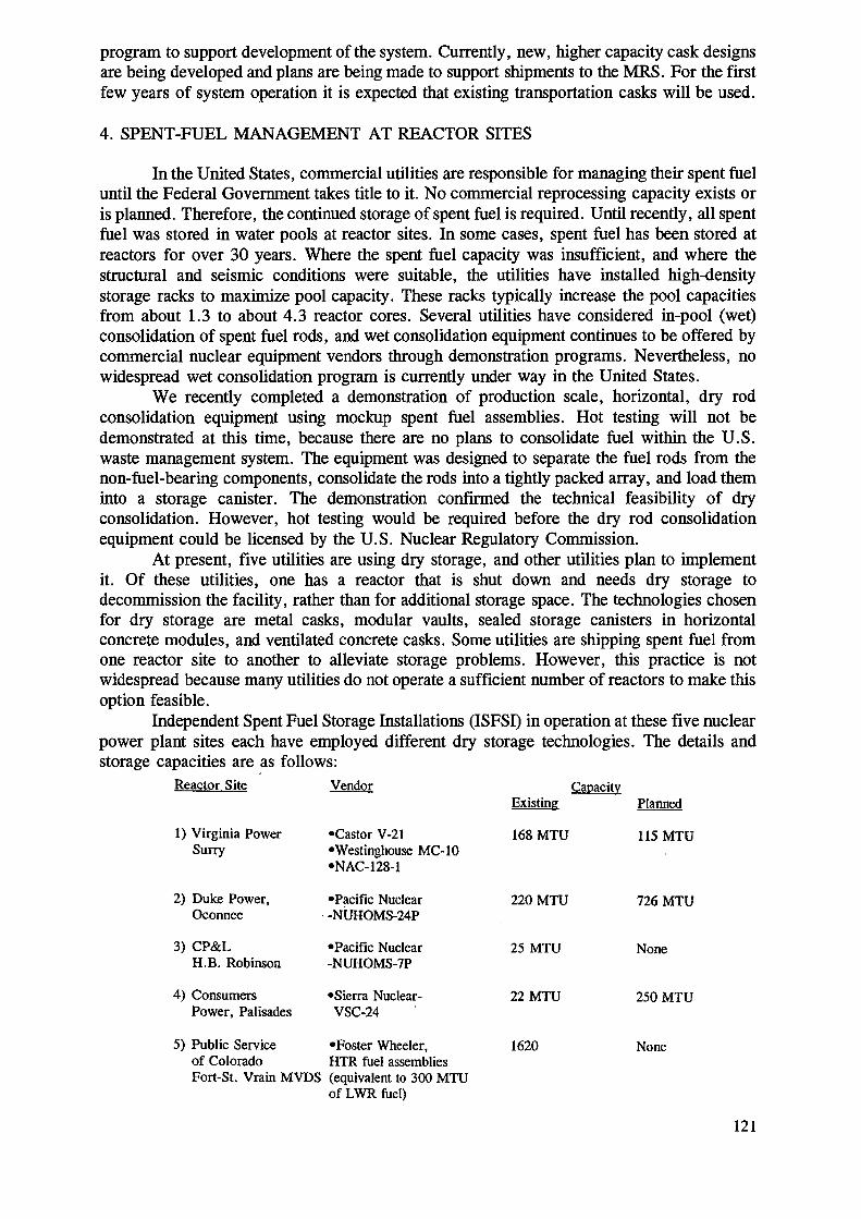
program to support development of the system. Currently, new, higher capacity cask designsare being developed and plans are being made to support shipments to the MRS. For the firstfew years of system operation it is expected that existing transportation casks will be used.
4. SPENT-FUEL MANAGEMENT AT REACTOR SITES
In the United States, commercial utilities are responsible for managing their spent fueluntil the Federal Government takes title to it. No commercial reprocessing capacity exists oris planned. Therefore, the continued storage of spent fuel is required. Until recently, all spentfuel was stored in water pools at reactor sites. In some cases, spent fuel has been stored atreactors for over 30 years. Where the spent fuel capacity was insufficient, and where thestructural and seismic conditions were suitable, the utilities have installed high-densitystorage racks to maximize pool capacity. These racks typically increase the pool capacitiesfrom about 1.3 to about 4.3 reactor cores. Several utilities have considered in-pool (wet)consolidation of spent fuel rods, and wet consolidation equipment continues to be offered bycommercial nuclear equipment vendors through demonstration programs. Nevertheless, nowidespread wet consolidation program is currently under way in the United States.
We recently completed a demonstration of production scale, horizontal, dry rodconsolidation equipment using mockup spent fuel assemblies. Hot testing will not bedemonstrated at this time, because there are no plans to consolidate fuel within the U.S.waste management system. The equipment was designed to separate the fuel rods from thenon-fuel-bearing components, consolidate the rods into a tightly packed array, and load theminto a storage canister. The demonstration confirmed the technical feasibility of dryconsolidation. However, hot testing would be required before the dry rod consolidationequipment could be licensed by the U.S. Nuclear Regulatory Commission.
At present, five utilities are using dry storage, and other utilities plan to implementit. Of these utilities, one has a reactor that is shut down and needs dry storage todecommission the facility, rather than for additional storage space. The technologies chosenfor dry storage are metal casks, modular vaults, sealed storage canisters in horizontalconcrete modules, and ventilated concrete casks. Some utilities are shipping spent fuel fromone reactor site to another to alleviate storage problems. However, this practice is notwidespread because many utilities do not operate a sufficient number of reactors to make thisoption feasible.
Independent Spent Fuel Storage Installations (ISFSI) in operation at these five nuclearpower plant sites each have employed different dry storage technologies. The details andstorage capacities are as follows:
Reactor Site Vendor CapacityExisting Planned
1) Virginia PowerSurry
2) Duke Power,Oconnee
3) CP&LH.B. Robinson
4) ConsumersPower, Palisades
•Castor V-21•Westinghouse MC-10•NAC-128-1
•Pacific Nuclear•NUHOMS-24P
•Pacific Nuclear•NUHOMS-7P
•Sierra Nuclear-VSC-24
5) Public Service «Foster Wheeler,of Colorado HTR fuel assembliesFort-St. Vrain MVDS (equivalent to 300 MTU
of LWR fuel)
168 MTU
220 MTU
25 MTU
22 MTU
1620
115 MTU
726 MTU
None
250 MTU
None
121
There are other utilities with plans for dry storage at various stages of development.For example, BG&E, Calvert Cliffs have an NRC license for 750 MTU storage using PacificNuclear NUHOMS 24P technology, and similarity GPU are planning the first BWR fuel drystorage at Oyster Creek for 113 MTU using Pacific Nuclear-NUHOMS 52-B. In addition,Northern States Power at Prairie Island plan to store 463 MTU in Transnuclear TN-40 metalcasks, and Arkansas Power and Light are planning 444 MTU in VSC-24 by Sierra Nuclear.Two units (Trojan, and Yankee Rowe) have been permanently shut down and will betransferring spent fuel from the pools to dry storage.
To assist in the development of dry storage technology, we are participating in ademonstration program with the Sacramento Municipal Utility District in California at itsRancho Seco unit, which was prematurely shut down by a voters' referendum. Thisdemonstration program includes the exhibition and testing of a cask-to-cask transfer deviceto facilitate the transfer of fuel to dual-purpose storage-and-transportation casks.
We are working on a continuing basis with several nuclear utility industry groups toresolve issues of concern, including contractual, waste acceptance, and interface issues.
5. PROGRAM STRATEGY
The current strategy for accomplishing our mission revolves around two concepts:integration of the waste management system, and decoupling of the schedules for wasteacceptance and waste disposal. Integration will result in a system in which each element andcomponent is designed specifically to work with other elements and components. We areusing systems engineering to rigorously identify the safety, functional, and technicalrequirements that the system and each of its elements must meet. This will allow us todevelop the system in a timely, efficient, and cost-effective manner while meeting allrequirements for safety and environmental protection.
The advantages of decoupling waste acceptance from disposal stem from fundamentaldifferences between a repository and temporary storage. The repository is an unprecedentedundertaking. It must isolate wastes for thousands of years, relying principally on the naturalbarriers present at the site, and the capability for safe isolation must be demonstrated duringlicensing. Its development therefore requires years of scientific study, and challenges inlicensing can be expected.
The MRS, on the other hand, will be limited-lifetime plant whose safety is based onengineering, using simple and proven technologies and methods for handling and storingwaste. The uncertainties associated with its development and licensing are much smaller thanthose for the repository. Furthermore, we plan to develop the MRS at a volunteered site andthus expect a generally favorable institutional environment.
The new Secretary of Energy, Hazel O'Leary, has reviewed the program strategy andissued several directives that included the following:
1. A chief scientist for the repository program is to be named.2. Site-characterization activities at Yucca Mountain, Nevada, are to proceed as
planned.3. Outside input will be sought on:
(a) options for spent-fuel storage, and(b) alternative licensing strategies for the repository.
4. The development and use of multipurpose canisters for spent fuel is to beevaluated.
Directive 1 has already been implemented. More detail on items 2 and 3 is given inthe subsequent discussions of the repository and monitored retrievable storage. Item 4,
122

however, spans all elements of the waste-management system and is discussed separatelybelow.
6. MULTIPURPOSE CANISTERS
At reactor dry storage technologies have developed based on individual utilityeconomic considerations without specific concerns about standardization on the economicsof the total HLW management system. DOE has initiated a study to develop a standardizedmulti-purpose canister (MPC) suitable for their waste management system and compatiblewith at reactor storage.
The multipurpose canister (MPC) is a sealed metal canister designed for the storage,transportation, and disposal of spent fuel. It is intended to use MPC's in conjunction withseparate overpacks designed for each of these functions. The MPC will be shielded on thetop, to facilitate sealing and handling, but not shielded on the sides or bottom. Supplementalshielding will be provided by the overpacks. Once loaded with spent fuel, the MPC will notbe transported, stored, or handled outside a shielded overpack, transfer system, or facility.The MPC will provide nuclear criticality control for storage, transportation, and disposal.
We are evaluating both a medium and a large MPC. The medium MPC would be ableto accept 12 fuel assemblies from a pressurized-water reactor (PWR) or 24 assemblies froma boiling-water reactor (BWR); fully loaded, it would weigh approximately 75 Mg with atransportation overpack. The large MPC would accept 21 PWR assemblies or 40 BWRassemblies; it would weigh approximately 125 Mg with a transportation overpack.
The MPC would be used at reactor sites for both onsite dry storage and for transporta-tion from the site. The empty MPC would be delivered to the reactor site either from theMRS (inside a transportation overpack) to be loaded for immediate offsite transportation ordirectly from the fabricator without a transportation overpack. For onsite dry storage, theMPC would be first placed in a transfer cask operated and maintained by the utility. Thetransfer cask would be also used to facilitate using the MPC at as many facilities as possible.
Facilities that are unable to use MFCs, for handling or infrastructure reasons, willload uncanistered spent-fuel assemblies into truck casks for shipment to the MRS or therepository. The reference system with MFCs does not include the use of cask-to-cask transfersystems to load uncanistered assemblies into the MPC outside the spent-fuel pool.
We assume that 14 facilities will use the medium MPC, 88 facilities will use the largeMPC (including 32 facilities that will use a transfer cask to facilitate loading), and 19facilities will ship uncanistered spent fuel.
If the MPC concept is implemented it is expected to have the MFCs available for at-reactor dry storage beginning in 1998 and plan to provide 320 MFCs over the 5 years from1998 through 2002. Our estimates show that the MFC could accommodate 85% of the dry-storage requirements over this 5-year interval. (These requirements do not include shutdownreactors.)
There is strong support from the U.S. utilities, regulators and oversight groups for theMPC system concept.
7. REPOSITORY
Yucca Mountain, the candidate site for the repository, is about 100 miles northwestof Las Vegas, Nevada on lands controlled by the Federal Government, including the NevadaTest Site. The site is located in an arid region with sparse vegetation and few inhabitants.The rock is volcanic tuff, and the proposed repository would be constructed in the
123

unsaturated zone above the water table. The Yucca Mountain site has not been selected fora repository. Rather, it has been designated by the Congress as the only candidate repositorysite to be characterized at this time. We will conduct a program of detailed scientificinvestigations and suitability evaluations to determine whether the site is suitable fordevelopment as a repository. If the candidate site is found to be suitable and is approved bythe President and the Congress, we will have to demonstrate to the NRC that the repositorysystem, including the site, meets regulations for radiation safety during operations and forlong-term isolation. If at any time the site is found to be unsuitable, we will stop work andwill notify the Congress as well as the Governor and the Legislature of Nevada of ourfindings. The plans, activities, and results of the investigations and evaluations will bereviewed on a continuing basis by the affected governments, the NRC, the Nuclear WasteTechnical Review Board, and other organizations external to the program.
An early site-suitability evaluation, completed last year, did not find any evidence ofconditions that would disqualify the site. Both the NRC and the Nuclear Waste TechnicalReview Board have testified before the Congress that, to date, there are no technical reasonsto believe that the site is unsuitable.
In the near term, our repository program will remain focused on the scientificinvestigations needed to determine whether the Yucca Mountain site has any features thatwould indicate it is not suitable for a repository. To achieve this goal, we are shifting effortsand resources from other programs to the Yucca Mountain project.
Our plans for site characterization includesurface-based testing and investigationsconducted in an exploratory-studies facility constructed to provide access to the undergroundrock formation in which a repository would be built. The surface-based testing supports theresolution of technical issues related to regional hydrology and ground-water flow rates,seismic hazards, and the potential for volcanic action. Since 1991 we have drilled 31 newboreholes and excavated 22 trenches and 106 soil pits.
An important milestone was achieved earlier this year when we began the constructionof the exploratory-studies facility by starting excavation for the north-portal starter tunnel.The next major step will be delivery of the tunnel-boring machine, scheduled for next spring.The machine will cut a 25-foot-diameter tunnel through the rocks at the site. We plan toconstruct two ramps from the surface to the underground, to complete more than 10 milesof underground excavations, and to develop a main test area to be used as an undergroundlaboratory.
We are continuing to develop the tools and techniques needed for assessing the safetyperformance of the repository system. Performance assessment is needed to support thedesign of the repository and the waste package and to perform demonstrations of regulatorycompliance that will be needed for licensing the repository. This effort will continue duringsite characterization. The repository and waste package designs will contribute additionalinformation that must be taken into account in assessing overall performance. Nevertheless,the tools and techniques that we now have are adequate for tasks that require only theavailable insights and data. We have therefore begun making preliminary assessments forearly evaluations of site suitability, for guiding the site-characterization program, and fordetermining preferred thermal loading parameters. These preliminary assessments shouldadvance consensus on the validity and applicability of the models we use in conductingperformance assessments.
Design activities for the repository and the waste package are at a phase we call theadvanced conceptual design. An important part of this design phase will be the incorporationof the multipurpose canister into the designs for the surface facilities of the repository, theramps and the underground repository, and the waste package. Before starting theconstruction of the repository we would have to complete two more design phases: the
124

license-application design, which will be submitted to the NRC in order to obtain aconstruction authorization, and the final procurement-and-construction design.
The current plan is directed at receiving a construction authorization from the NRC,building the repository, and starting to emplace significant quantities of waste as soon as theNRC issues a license to receive and possess waste. However, obtaining the constructionauthorization for a first-of-a-kind facility that must provide waste isolation for thousands ofyears will be an unprecedented task. This task will be complicated by the uncertaintiesassociated with both the engineered and natural barriers that can be expected to remain evenafter years of collecting information about the site.
Over the years various suggestions have been made about alternative approaches tolicensing and repository development, and Secretary O'Leary has decided to seek public inputon an alternative strategy developed by a task force. The proposed alternative approach istypical of that used in developing new large-scale technologies-namely, phased developmentand licensing. The first objective in this approach is to demonstrate that a repository wouldprovide the required waste isolation. Small-scale facilities could then be constructed foremplacing limiting quantities of waste, with the construction of full-scale facilities deferreduntil the design can be evaluated against the experience gained. The scale-up period couldlast for years and could be negotiated with affected parties. Another option would be tolicense a repository for long-term storage, with the waste remaining fully retrievable.
8. MONITORED RETRIEVABLE STORAGE
The Amendments Act authorizes two paths for MRS siting.(1) siting by the DOE, through a process of survey, evaluation, and selection, and(2) siting through the efforts of the Nuclear Waste Negotiator.
Our present strategy is based on siting through the Negotiator, but we are developinga contingency siting plan and will decide on the basis of the MRS schedule and the status ofexternal efforts as to the appropriateness of implementing that contingency plan.
In developing a proposed agreement with the Negotiator, a host State or Indian Tribecan negotiate for itself an active role in MRS development and operations. By participatinghi decision making and by exercising rigorous oversight of MRS activities, the host canassure itself that the MRS will perform to its satisfaction, meet community standards, andserve community goals.
The Amendments Act provides for funding to interested States, Indian Tribes, andaffected units of local government to investigate the feasibility of hosting an MRS. In June1991, the DOE and the Negotiator published notices that a restricted eligibility solicitationwas available and invited eligible States, Indian Tribes, and affected units of localgovernment to submit applications for grants of financial assistance. The Negotiator receivedmany expressions of interest hi learning more about hosting an MRS. To date, 12 first-phasegrant applications have been received and granted. Four of the recipients, all Indian Tribes,have completed the initial study and have applied for second-phase grants, which providefunding for more-detailed assessments. This summer, two Tribes that completed the secondphase of the assessment requested funding for the final step in the feasibility-assessmentprocess. Thus, though no volunteer site for the MRS has yet been found, the results areencouraging, and we continue to support the Negotiator's efforts.
Our own efforts hi the last year or so were concentrated on developing a conceptualdesign for the facility. An MRS must have facilities for both handling and storing spent fuel,and there are several proven design concepts for these functions. We identified more than20 combinations of possible storage-and-handling concepts. We developed an MRSconceptual design, which further develops a number of possible storage and handling con-
125
cepts. Until a site is identified, further design activities would be unproductive. The next stepwill be to develop a more-refined and more-detailed design that accommodates the MPCconcept as well as site-specific conditions.
The MRS must be licensed by the NRC, and licensing should be expedited by ourdecision to, insofar as is practical, incorporate into the MRS design already licensedconcepts. We prefer to use technologies already licensed or certified by the NRC or a designthat closely approximates that of existing licensed facilities. We also intend to conductprelicensing interactions with the staff of the NRC to identify licensing issues and beginworking to resolve them.
9. TRANSPORTATION
For shipping spent fuel from reactor sites to the MRS, we are developing new-generation casks, with capacities greater than those of existing casks, for shipments by truck,rail, or barge. Before any casks are constructed, their designs will have to be certified by theNRC. We have chosen two companies to develop the final cask designs and obtain thecertificates of compliance from the NRC. Once the certificates of compliance are issued, caskprototypes will be fabricated and tested, and the fabrication of the cask fleet can then begin.If a decision is made to use the multipurpose canisters, we will develop plans to acquirecompatible overpacks for transportation.
Our basic strategy is to be ready for transportation operations as soon as an MRS isready to receive spent fuel. If the high-capacity casks or overpacks cannot be available ontime, we may exercise the option of acquiring shipping casks or overpacks based on existingtechnologies. Decisions about implementing this option will be made when an MRS site hasbeen identified. Another option is to use the existing commercial fleet of casks for the startof transportation operations.
We will also establish the capability for transportation operations. Besides the shippingcasks and other equipment, we will require the services of contractors who will providetransportation, maintain and inspect equipment, plan and schedule operations, and trainpersonnel. In addition, we will provide technical assistance and funds to States for trainingthe public-safety officials of local governments and Indian Tribes through whose jurisdictionswastes will be shipped. We have developed, in consultation with interested parties, a strategyfor providing this assistance.
10. APPROACH TO ENSURING SAFETY
Safety is our primary responsibility. Federal laws and regulations require us to site,construct, and operate the waste-management system in a manner that will provide reasonableassurance that the health and safety of the public, the workers, and the environment will beprotected. The MRS and the repository must meet the applicable environmental standardsestablished by the EPA and implemented by NRC regulations.
The NRC is required to promulgate the regulations it will use in approving ordisapproving licenses for various waste management activities. The NRC serves as alicensing/regulatory authority charged with the task of reviewing the license application toverify that regulatory compliance has been achieved.
Our policy for ensuring safety is to make each line element in the organizationresponsible and accountable for quality and safety in its operations and in employing a well-organized oversight/review system to assure effective implementation of safety programsduring all phases of the program.
126
Our basic safety approach includes early definition of safety requirements and theirincorporation into plans; systematic identification, assessment and elimination/mitigation ofhazards; review for safety compliance prior to incorporating any changes to established plans;and periodic oversight reviews by external peer groups, as appropriate.
We base our technical approach to safety on the defense-in-depth concept. Defense indepth requires the use of complementary engineered and natural barriers to contain andisolate the waste for the required period of time. A series of multiple engineered barriers willbe employed to contain radioactive materials in the short to near term, with gradual releaseof radionuclides in the long term into the series of natural barriers. This facilitates long-termisolation by inhibiting the transport of radionuclides released by the engineered barriers.
To support our safety case for the repository, we are conducting many studies andextensive research into such issues as radionuclide source terms, accident scenarios,radionuclide retardation, and the validation of performance assessment codes. The results ofthese studies will play a significant role in our demonstration of compliance with NRCregulations, which has to be defensible and technically robust in an open public forum.
The INEL has been conducting a dry storage test and demonstration program since1985. In 1985 and 1986, three casks were tested by placing fuel assemblies in the GNSCastor V/21, Westinghouse MC-10, and Transnuclear TN-24P metal casks. Fuel rods from48 assemblies were subsequently consolidated into 24 canisters, which were tested in the TN-24P. In 1989, 17 of those canisters were used to test the Pacific Sierra Nuclear VSC-17concrete cask. A series of five reports published by DOE and Electric Power ResearchInstitute (EPRI) contains the test descriptions, data, analyses, and results. Data and analysesare also archived at INEL and Pacific Northwest Laboratories (PNL). Results from thisproject will add to the existing body of knowledge on dry storage by addressing long-termstorage effects on spent fuel.
In preparation for the cask tests, the fuel was visually inspected, video taped, andphotographed in color and black-and-white. During the test program, some gas samplesindicated leaking rods, but subsequent samples showed none. After the fuel was placed in thecasks, gas samples and radiation measurement were taken periodically until August 1988,when gas sampling was terminated. The fuel had become stable, and further gas samplingwas not required for safe storage.
We will initiate a project in October 1993 to obtain additional information and dataon the performance of spent nuclear fuel under long-term dry storage conditions usingfacilities at INEL.
Currently, the V/21 is fully loaded with 21 fuel assemblies; the MC-10 has capacityfor 24 assemblies and contains 18; the TN-24P has capacity for 24 assemblies and contains7 consolidated fuel canisters; and the VSC-17 is rally loaded with 17 consolidated canisters.Routine monitoring includes visual surveillance of the casks, monitoring of the gas pressureinside the casks, monitoring of the radiation fields around the casks, and periodic samplingof the soil around the cask storage pad.
11. PROGRAM MANAGEMENT AND EXTERNAL RELATIONS
A fundamental element of our management strategy is managing for quality. Itincludes not only a formal program of quality assurance, but also quality in all aspects of ourwork. We have in place a quality-assurance program that meets the requirements establishedby the NRC. The development and implementation of this program represents one of thelargest and most concentrated commitments of time and effort since the inception of thewaste-management program. We participate in bimonthly quality-assurance meetings with theNRC to discuss our quality-assurance status and programs.
127

A program as complex and long lasting as ours requires good planning and control.To provide this control we use a set of integrated baselines-that is, reference sets of dataand requirements that are strictly controlled—for technical work, costs, and schedules. Tocontrol changes to the program, we have set for each baseline thresholds that may not beexceeded without approval by the appropriate level of management.
To enhance efficiency and to assist in implementing the program, we use systemsengineering to plan, control, and integrate technical activities. Specifically, systemsengineering is used to specify the sequence of technical activities necessary to define thetechnical requirements the system must satisfy, to develop the system, to relate the systemelements to each other, and to determine how the system can be optimized to most effectivelysatisfy the requirements.
Recognizing that success in this undertaking will depend to a large extent on oursuccess in earning the trust and confidence of the public, we are initiating an institutionalstrategy aimed at expanding and improving our interaction and our communication withaffected governments, interested parties, and the general public. One step in this directionwas a series of workshops we held over the past year with representatives of affectedgovernments and key interested parties. The purpose was to receive input on a wide rangeof important program issues. We continued this initiative by holding a Director's Forum tosolicit the views of external parties on various program issues.
We have had valuable interchanges with the various external bodies that review ourprogram. The Nuclear Waste Technical Review Board, which evaluates the technical andscientific validity of the activities that we will conduct, has played a key role. The NationalAcademy of Sciences has also contributed. The Secretary of Energy Advisory Board hasestablished a task force that is concerned with the institutional framework of the program.Moreover, we are increasingly using peer review in all appropriate aspects of programdevelopment.
128
LIST OF PARTICIPANTS
CanadaBrown, P.
Naqvi, SJ.
FranceGerster-Marin, D.
Saverot, P.
Radioactive Waste and Radiation, Electricity Branch,Energy, Mines and Resources580 Booth Street,Ottawa, Ontario K1A OE4
Ontario Hydro,700 University Avenue, HI 3 G25,Toronto, Ontario M5G 1X6
CEA — Direction du cycle combustible,CEN/Saclay,F-91191 Gif-sur-Yvette Cedex
NUSYS,89, rue de Tocqueville,F-75017 Paris
GermanyPeehs, M.
HungaryBuday, G.
Ferenczi, G.
IndiaBajpai, D.D.
JapanMaeda, M.
Maruyama, Y.
Siemens AG, KWU/BP,P.O. Box 3220,D-8520 Erlangen
Paks Nuclear Power Plant,P.O. Box 71,H-7031 Paks
Department of Nuclear Technology,ETV-ERÖTERV-RT,V. Széchenyi RKP 3,H-1054 Budapest
Prefre Plant,P.O.Taps, Thane District,Maharashtra - 401504,Tarapur
Dept. of Fuel Cycle Safety Research,Tokai Research Establishment JAERI,Tokai-mura, Ibaraki-ken, 319-11
Nuclear Fuel Division,Atomic Energy Bureau, STA,2-2-1- Kasumigasek,Chiyodaku, Tokyo 100
129

Shimizu, T.
Korea, Rep. ofPark, Won J.
Russian FederationRomanovskij, V.N.
Tikhonov, N.
Slovak RepublicKmosena, J.
Nuclear Fuel Cycle Engineering Division,Power Reactor and Nuclear Fuel DevelopmentCorporation,1-9-13 Akasaka, Minato-ku,Tokyo 100
Korea Institute of Nuclear Safety,P.O. Box 16,Daeduk-danji, Taejeon
Radievii Institute,Rentgena 1,197022 Saint Petersburg
All-Union Scientific & Planning Institute of ComplexPower (VNIPIET),Dibunovskaja Street 55,197228 Saint Petersburg
Nuclear Power Plant Bohunice,91931 Jaslovske Bohunice
SwedenVogt, J. Swedish Nuclear Fuel and Waste Management Co.,
P.O. Box 5864,102 48 Stockholm
SwitzerlandOspina, C.
United KingdomCrossan, I.F.
Dodds, R.
United States of AmericaWilliams, J.
Institut Paul Scherrer,CH-5232 Villigen
HM Nuclear Installations Inspectorate,St. Peter's House, Stanley Precinct,Bootle, Merseyside L20 3LZ
British Nuclear Fuels pic,Risley, Warrington, WA3 6AS
Office of Civilian Radioactive Waste Management,RW-40 US Department of Energy,1000 Independence Avenue, S.W.,Washington, DC 20585
130
IAEABaschwitz, R.
Grigoriev, A.(Scientific Secretary)
Oi, N.
F. Takâts(Scientific Secretary)
Division of Nuclear Fuel Cycle and Waste Management,International Atomic Energy Agency,Wagramerstrasse 5,P.O. Box 100,A-1400 Vienna, Austria
Nuclear Materials and Fuel Cycle Technology Section,Division of Nuclear Fuel Cycle and Waste Management,International Atomic Energy Agency,Wagramerstrasse 5,P.O. Box 100,A-1400 Vienna, Austria
Nuclear Materials and Fuel Cycle Technology Section,Division of Nuclear Fuel Cycle and Waste Management,International Atomic Energy Agency,Wagramerstrasse 5,P.O. Box 100,A-1400 Vienna, Austria
Nuclear Materials and Fuel Cycle Technology Section,Division of Nuclear Fuel Cycle and Waste ManagementInternational Atomic Energy Agency,Wagramerstrasse 5,P.O. Box 100,A-1400 Vienna, Austria
131