speedwing 250 mk ii assembly instructionsspeedwing.net/sw250_mk2_instructions.pdf · speedwing 250...
TRANSCRIPT

SpeedWing 250 Mk IIAssembly Instructions
SPECIFICATIONSWingspan: 24 in.
Wing Area: 168 sq. in.Target Weight: 7.4 oz.
Wing Loading: 6.4 oz./sq. ft.Motor: Johnson 250 (two incl. w/props)
RADIO EQUIPMENT NEEDED2 Micro Servos (HS-55 or equivalent)
Micro Receiver (GWS 4P or Berg MS4P)Micro Speed Control (10 amp)
2 Cell 1200 ETEC or 3-cell 800mah (for Brushless)Optional: 20mm BL Inrunner ~3000Kv
Website: www.speedwing.nete-mail: [email protected]
SpeedWing 250 Mk II InstructionsThank you for choosing the SpeedWing 250 Mk II as your next project. This kit is easy to build and only requires a few hours to complete. Once finished, you will be rewarded with a stable, FAST, fun to fly wing that you can take anywhere. It is the perfect “take to work” plane to fly on those lunch breaks or to stop by the park on the way home. Although this kit isn’t recommend-ed for beginners because of its high speed and agility, once you master the basics of flying R/C planes you can handle this plane. Well lets get started. Below is a list of supplies and tools needed to complete the SpeedWing 250 Mk II.
Supplies:
- Industrial Strength Velcro Tape (for battery attachment) - Pen - 5 minute epoxy - Thin CA (Superglue) - Medium CA - CA Accelerator - 150 Grit Sand Paper (or equivalent) - Xacto knife - Dremel Tool (optional) - Two sided foam tape (for servo anchor) - 3M #600 3/4” Scotch Tape, or Clear Packing Tape (for hinges) - Covering tape or Low Heat iron on covering (I use Solarfi lm) - 1” strapping tape (has fi bers imbedded in it) - 3M 77 Spray Adhesive - Micro EZ Connectors
Radio Equipment:
- 4 channel receiver (Berg MicroStamp 4L or Blue Bird BMG 04) - Micro Servos - 2 (HS-55 or equivalent) - Small Speed Control (10A Brushed or appropriate Brushless ESC) - 2-cell 1200mah LiPoly (Brushed) or 3-cell 800 mah LiPoly (Brushless) - J250 Motor (Included) or 20mm Brushless motor (use approx 3000 Kv Motor)
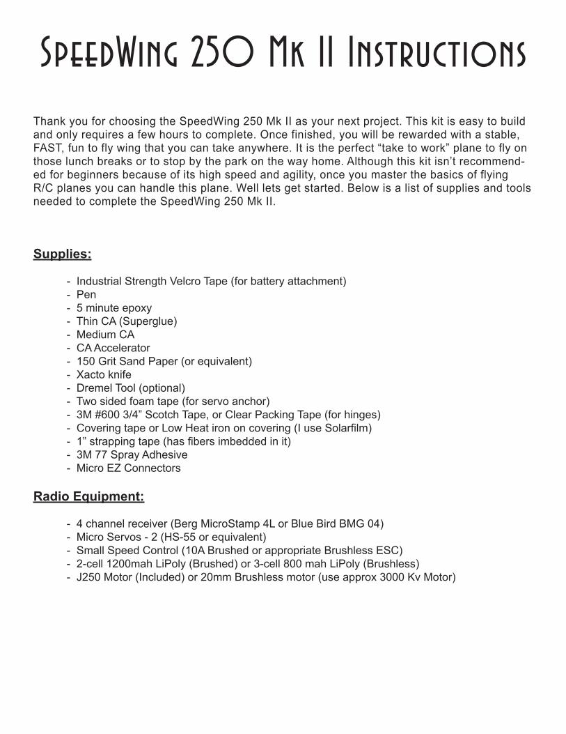
1. Find the three parts of the motor mount. You can smooth the edges of the motor mount doublers if you’d like.
2. Use 5-minute epoxy to glue the ply doublers to the motor mount. Make sure that you align the doublers correctly and hold them in place until the epoxy dries.
3. Now place the mount along one wing core and mark where the ply doublers come in contact with the foam. This foam will have to be cut from the cores so that the motor mount can be glued fl ush to the cores.
4. Now use a sharp X-acto blade and cut the foam along the marks you have made.
5. Glue the mount to one wing core with 5-minute epoxy. Use just enough epoxy to cover the root of the wing. To help hold the wing in place, use a couple of strips of masking tape.
6. Glue the remaining wing to the motor mount using epoxy. Again, use masking tape to help hold the wing to the motor mount while the glue dries. Make sure the wing cores are in perfect alignment with the motor mount.
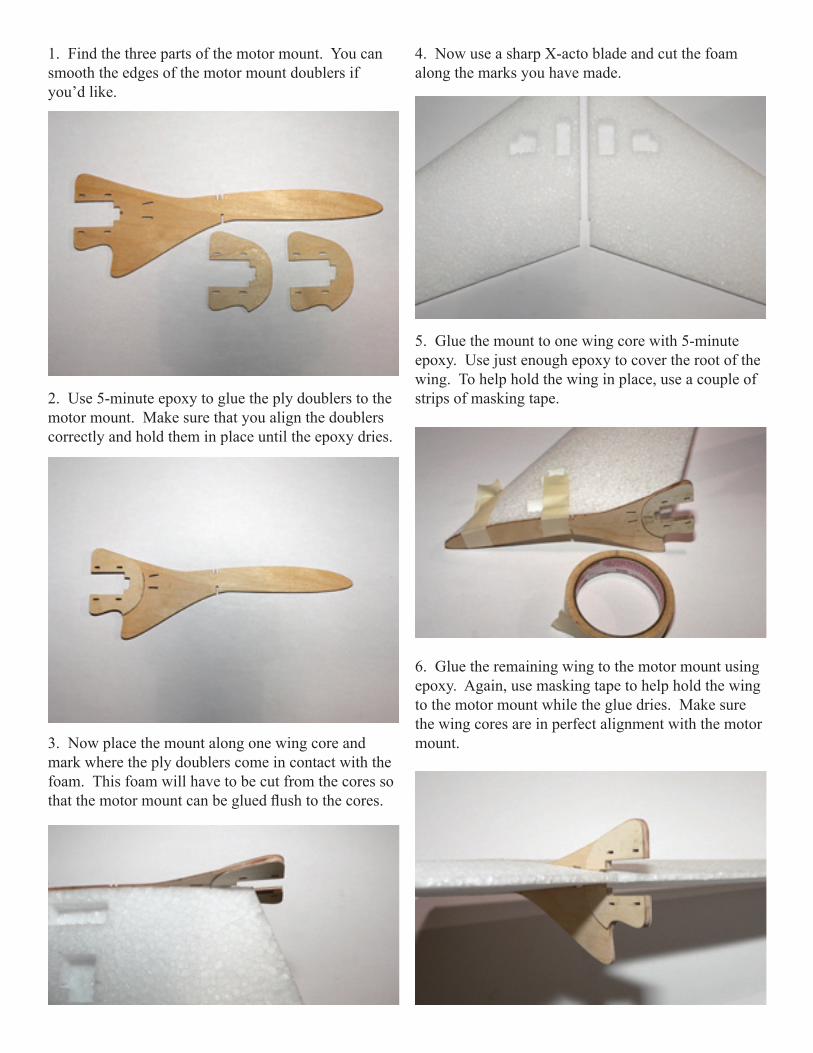
7. Insert the motor into the motor mount. You will need to mark where the motor fi ts into the mount and cut a small amount of foam out of the wing so that the motor can slide all the way forward.
Installing the Carbon Fiber Flats
IMPORTANT: Be very careful during the next few steps when handling the Carbon Fiber Flats. DO NOT run your fi ngers or hand along the CF Flats as you will get carbon splinters. When cutting or sanding any Carbon Fiber be sure to wear a dust mask or respirator.BE CAREFUL.
1. Place the wing in the bottom wing beds and place on a fl at surface. (Note: you will have to place the wing beds on top of something (like a couple of short 2x4’s) so that it can sit level on the table).
2. Tape one of the CF fl ats to the top of the wing. There are two slots in the motor mount, the CF Flat goes through the rear slot.
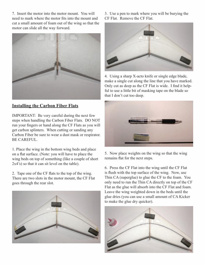
3. Use a pen to mark where you will be burying the CF Flat. Remove the CF Flat.
4. Using a sharp X-acto knife or single edge blade, make a single cut along the line that you have marked. Only cut as deep as the CF Flat is wide. I fi nd it help-ful to use a little bit of masking tape on the blade so that I don’t cut too deep.
5. Now place weights on the wing so that the wing remains fl at for the next steps.
6. Press the CF Flat into the wing until the CF Flat is fl ush with the top surface of the wing. Now, use Thin CA (superglue) to glue the CF to the foam. You only need to run the Thin CA directly on top of the CF Flat as the glue will absorb into the CF Flat and foam. Leave the wing weighted down in the beds until the glue dries (you can use a small amount of CA Kicker to make the glue dry quicker).
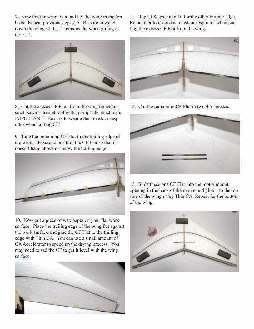
7. Now fl ip the wing over and lay the wing in the top beds. Repeat previous steps 2-6. Be sure to weigh down the wing so that it remains fl at when gluing in CF Flat.
8. Cut the excess CF Flats from the wing tip using a small saw or dremel tool with appropriate attachment. IMPORTANT! Be sure to wear a dust mask or respi-rator when cutting CF!
9. Tape the remaining CF Flat to the trailing edge of the wing. Be sure to position the CF Flat so that it doesn’t hang above or below the trailing edge.
10. Now put a piece of wax paper on your fl at work surface. Place the trailing edge of the wing fl at against the work surface and glue the CF Flat to the trailing edge with Thin CA. You can use a small amount of CA Accelerator to speed up the drying process. You may need to sad the CF to get it level with the wing surface.
11. Repeat Steps 9 and 10 for the other trailing edge. Remember to use a dust mask or respirator when cut-ting the excess CF Flat from the wing.
12. Cut the remaining CF Flat in two 4.5” pieces.
13. Slide these one CF Flat into the motor mount opening in the back of the mount and glue it to the top side of the wing using Thin CA. Repeat for the bottom of the wing.
Radio Installation:
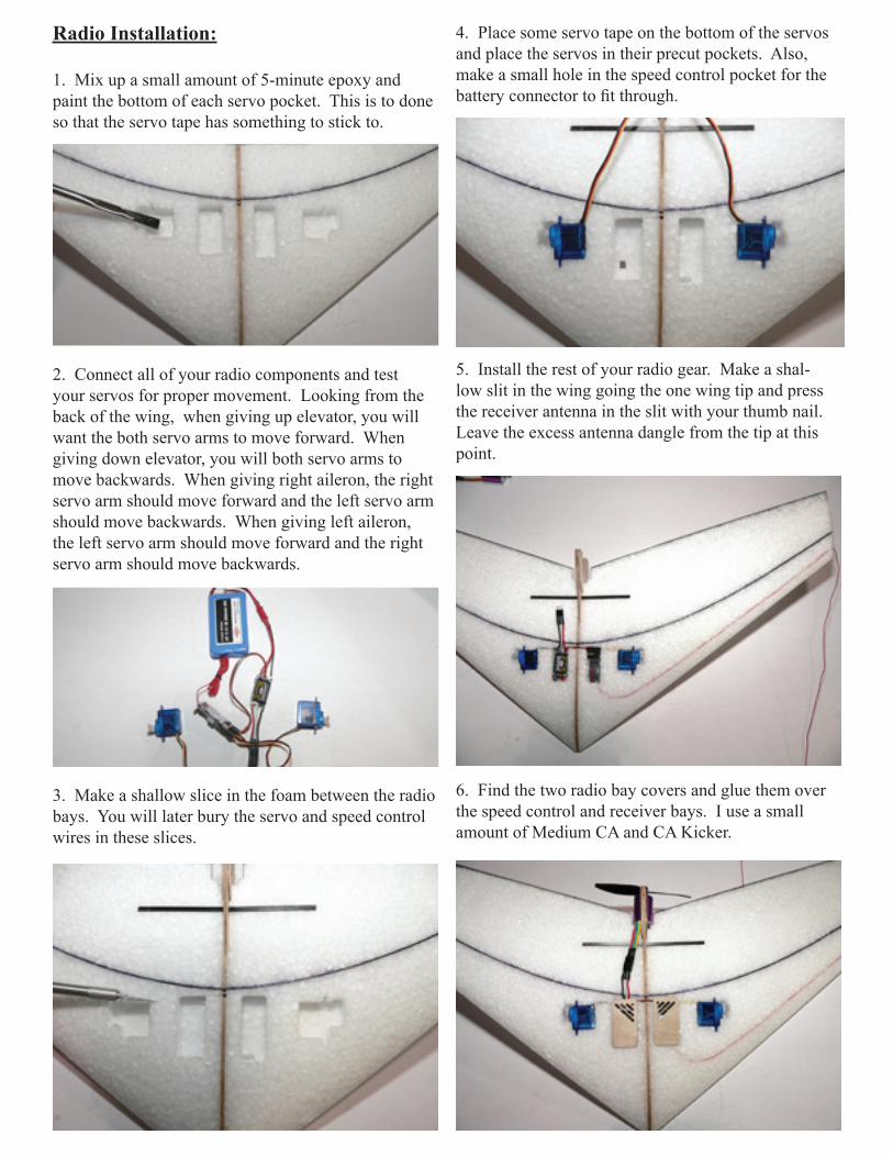
1. Mix up a small amount of 5-minute epoxy and paint the bottom of each servo pocket. This is to done so that the servo tape has something to stick to.
2. Connect all of your radio components and test your servos for proper movement. Looking from the back of the wing, when giving up elevator, you will want the both servo arms to move forward. When giving down elevator, you will both servo arms to move backwards. When giving right aileron, the right servo arm should move forward and the left servo arm should move backwards. When giving left aileron, the left servo arm should move forward and the right servo arm should move backwards.
3. Make a shallow slice in the foam between the radio bays. You will later bury the servo and speed control wires in these slices.
4. Place some servo tape on the bottom of the servos and place the servos in their precut pockets. Also, make a small hole in the speed control pocket for the battery connector to fi t through.
5. Install the rest of your radio gear. Make a shal-low slit in the wing going the one wing tip and press the receiver antenna in the slit with your thumb nail. Leave the excess antenna dangle from the tip at this point.
6. Find the two radio bay covers and glue them over the speed control and receiver bays. I use a small amount of Medium CA and CA Kicker.

7. Now use some masking tape to cover the motor mount. Spray a light coat of 3M77 spray on the top and bottom of the wing.
8. Place a strip of strapping tape along the leading edge of the wing. The strapping tape helps prevent the leading edge from becoming damaged when hitting sharp objects.
9. Find the two elevons. Sand a 45 degree angle on the leading edge of each elevon. Make sure you make a right and a left elevon. Also, lightly bevel the under-side of each elevon. This will make the wing faster as you will need less refl ex to fl y (up elevator).
Covering Instructions
You can cover the model either with colored covering tape or iron on fi lm. I like to use either Solarfi lm or Econokote to cover with. Both are low-temp coverings and are easy to work with. If you don’t have experience or the tools to cover with iron on fi lms, colored covering tape works well and is easy to use. I like to use two contrasting colors so that it is easy to keep orientation while fl ying.
1. Start by covering one side of the bottom of the wing. Lay the part of the wing you want to cover over the covering fi lm and mark out where to cut the cover-ing. Leave at least 1.5” excess around the wing.
2. Use low heat settings on your iron and stick the covering to the center of the wing. Then stretch the covering and iron it to the tip of the wing. Now, stretch the covering and iron it to the leading and trail-ing edges. You will shrink the center of the covering after you cover the whole wing. Trim excess covering.
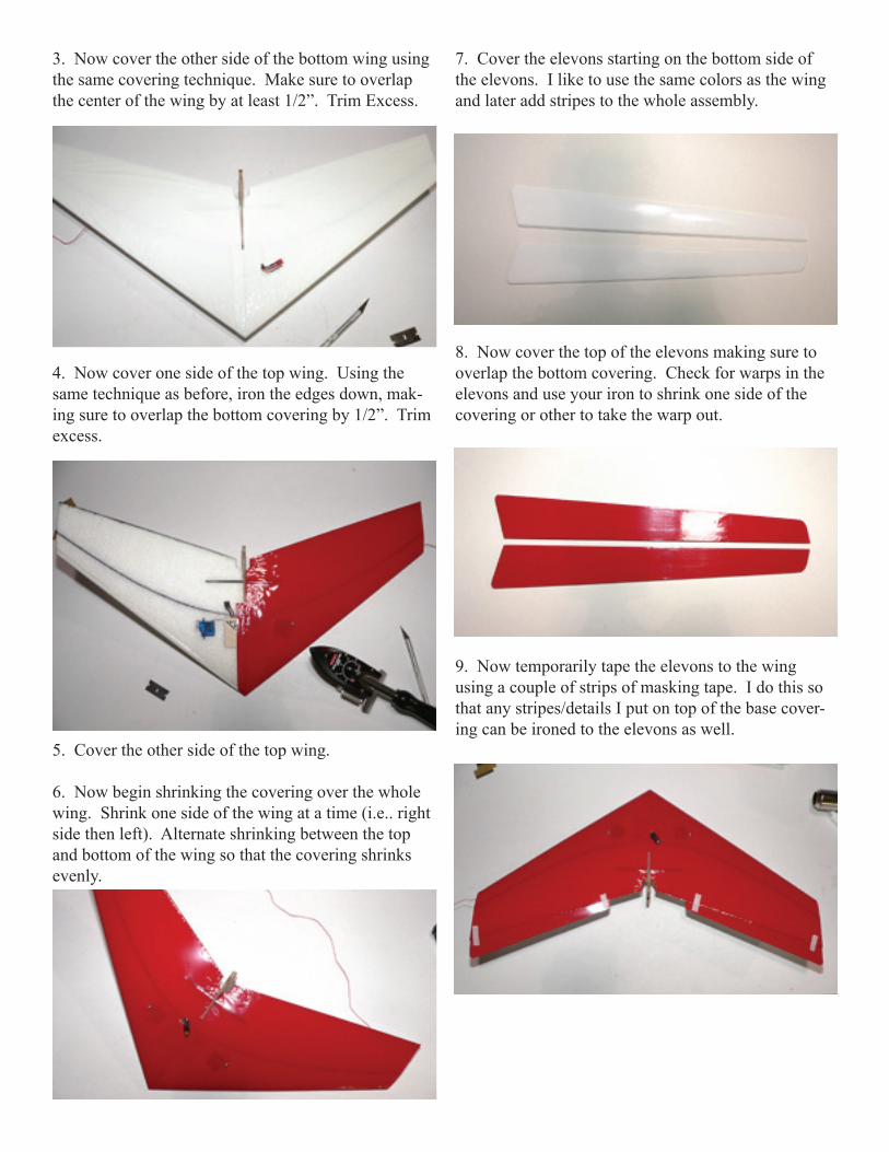
3. Now cover the other side of the bottom wing using the same covering technique. Make sure to overlap the center of the wing by at least 1/2”. Trim Excess.
4. Now cover one side of the top wing. Using the same technique as before, iron the edges down, mak-ing sure to overlap the bottom covering by 1/2”. Trim excess.
5. Cover the other side of the top wing.
6. Now begin shrinking the covering over the whole wing. Shrink one side of the wing at a time (i.e.. right side then left). Alternate shrinking between the top and bottom of the wing so that the covering shrinks evenly.
7. Cover the elevons starting on the bottom side of the elevons. I like to use the same colors as the wing and later add stripes to the whole assembly.
8. Now cover the top of the elevons making sure to overlap the bottom covering. Check for warps in the elevons and use your iron to shrink one side of the covering or other to take the warp out.
9. Now temporarily tape the elevons to the wing using a couple of strips of masking tape. I do this so that any stripes/details I put on top of the base cover-ing can be ironed to the elevons as well.

10. There are vinyl graphics included in the kit. To install them, tape the decal to the wing using a strip of masking tape about 3 1/8” from the tip of the wing.
11. Peel back the top of the graphic.
12. Cut the transfer backing off.
13. Using a plastic squeegee or a credit card, press the graphic down working your way from the center of the graphic out and towards the front.
14. Be sure to press the graphic down along the lead-ing edge.
15. Peel the masking tape off.

16. Now peel the rest of the transfer backing off of the graphic.
17. Press the rest of the graphic down working your way from the center of the graphic towards the back of the wing. Be sure to hold the elevon straight when applying the graphic.
18. Bend the elevon up and cut the graphic along the hinge line using a sharp X-acto or single edge blade.
19. Carefully peel the backing off of the top of the graphic. Be sure to pull at an angle and horizontal to the graphic.
20. Carefully go over the top of the graphic again to make sure all the edges are stuck to the covering.
21. Repeat steps 10 - 20 for the other graphic.
22. Apply any other covering scheme you’d like to the rest of the wing.
23. Remove the elevons.

Final Assembly
1. Start by installing the elevons on the wing. You can use clear packing tape or dubro hinge tape. Lay the tape upside down on the building surface, then lay an elevon upside down over the tape. Trim the tape to the ends of the elevon.
2. Tape the elevon to the wing while giving the elevon full defl ection.
3. Tape the underside of the elevon to the wing while the elevon is fl ipped up.
4. Find the coroplast tiplets. Now make a mark from the tip of the tiplet to the back. You will glue the tiplet to the wing with this line on the center line of the air-foil. Sand the tiplet where it will be glued to the wing.
5. Glue the Right tiplet to the elevon using medium CA and CA accelerator. Use the marks on the tiplets as a guide to align them properly.
6. Make a small hole on the inside of the left tiplet and pull the antenna through the hole into one of the corrugated fl utes. Now glue the left tiplet on with med. CA. Run the antenna back and forth through the tiplet fl utes leaving a few inches hanging out of the back of the tiplet.

7. Using a straight edge, mark the location of the 1/2A control horns on the elevons.
8. Mount the control horns making sure that the push rod holes are directly above the hinge line. You can use an X-acto to make a small starter hole for the control horns to press into. Use medium CA to glue in control horns.
9. Install the Micro EZ connectors on the servo horn. (I use the second hole from the bottom of the servo horn).
10. Make a Z-Bend in one end of each push rod.
11. Attach the Z-Bend end of the push rod to the top hole in the elevon control horns. Slide the other end though the Micro EZ Connects and tighten the screw when the elevons are level. Cut off excess wire.
13. Attach the motor using the tie wraps included in your kit.
12. Cut the covering off of the cooling holes in the speed control cover. You can cut them off of the re-ceiver cover as well, but it isn’t necessary.
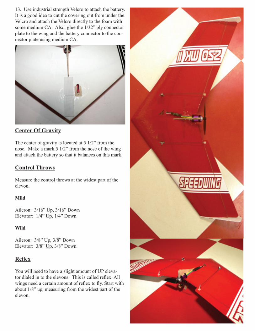
13. Use industrial strength Velcro to attach the battery. It is a good idea to cut the covering out from under the Velcro and attach the Velcro directly to the foam with some medium CA. Also, glue the 1/32” ply connector plate to the wing and the battery connector to the con-nector plate using medium CA.
Center Of Gravity
The center of gravity is located at 5 1/2” from the nose. Make a mark 5 1/2” from the nose of the wing and attach the battery so that it balances on this mark.
Control Throws
Measure the control throws at the widest part of the elevon.
Mild
Aileron: 3/16” Up, 3/16” DownElevator: 1/4” Up, 1/4” Down
Wild
Aileron: 3/8” Up, 3/8” DownElevator: 3/8” Up, 3/8” Down
Refl ex
You will need to have a slight amount of UP eleva-tor dialed in to the elevons. This is called refl ex. All wings need a certain amount of refl ex to fl y. Start with about 1/8” up, measuring from the widest part of the elevon.