speed regulator and hysteresis based on artificial
TRANSCRIPT
Revue des Energies Renouvelables Vol. 20 N°2 (2017) 231 - 242
231
Speed regulator and hysteresis based on artificial intelligence
techniques of three-level DTC with 24 sectors for induction machine
H. Benbouhenni 1* and R. Taleb 2†
1 Department of Electrical Engineering, National Polytechnic School Oran, Algeria
2 Department of Electrical Engineering, University of Chlef, Chlef, Algeria
(reçu le 10 Mai 2017 - accepté le 30 Juin 2017)
Abstract - Direct torque control (DTC) of induction motor (IM) is important in many
applications. In this paper presents a three-level direct torque control with 24 sectors is
applied for IM using PI-flou controller and hysteresis regulators based in artificial
intelligence techniques. The DTC system is known to offer fast decoupled control between
torque and flux via a simple control structure. Nevertheless, DTC system has two major
drawbacks, with are the variable inverter switching frequency and high torque output
ripple. The validity of the proposed control scheme is verified by simulation tests. The
stator flux, torque, and current are determined and compared to the above technique.
Résumé - Le contrôle direct de couple (DTC) d'un moteur à induction (IM) est important
pour de nombreuses applications. Cet article présente une commande directe du couple à
trois niveaux avec 24 secteurs appliquée aux IM en utilisant un contrôleur PI-flou et des
régulateurs hysterisis basé sur des techniques d'intelligence artificielle. Le système DTC
est connu pour sa capacité à offrir un contrôle découplé rapide entre le couple et le flux à
travers une structure de commande simple. Néanmoins, les systèmes DTC ont deux
inconvénients majeurs qui sont la variabilité de la fréquence de commutation de
l'onduleur, et les ondulations de sorties élevées pour le couple. La validité du schéma de
contrôle proposé est vérifiée par des simulations. Le flux du stator, le couple, et le
courant sont déterminés et comparés aux techniques précédemment citées.
Keywords: Induction motor - Direct torque control - PI-flou - Neural hysteresis - Sectors
- Fuzzy hysteresis.
1. INTRODUCTION Induction motors (IMs) are suitable electromechanical systems for a large spectrum
of industrial applications. This is due to their high reliability, relatively low cost, and
modest maintenance requirements. However, IMs are known as multivariable nonlinear
time-varying systems. Thus makes their control so difficult, mainly in variable speed
applications [1].
Recent advances in power semiconductor and microprocessor technology have made
possible the application of advanced control techniques to alternating current (AC)
motor drive systems [2].
There are two must common AC drives control schemes that are being widely
researched. One of it is field oriented control (FOC) which was proposed by Takahashi
and Noguchi. There are two major drawbacks of FOC compared to the DTC which are
torque is controlled indirectly and requirement of the pulse encoder. In FOC method of
control the torque indirectly because its control priority is flux vector. FOC needs the
pulse encoder in order to obtain the speed and position of the rotor.
This makes the DTC system as an alternative and gained the attention of many
researchers lately due to its simple structure by elimination of pulse encoder and simple
algorithm with lesser dependency on motor parameters (only requires value of stator
A. Benbouhenni et al.
232
resistance sR and phase current). Over the past years, the utilization of multilevel
inverter topology in the DTC system has gained popularity for the medium and high
voltage applications [3].
Direct torque control, as one of the high-performance AC drives, was extended to
the field of multi-level inverters in the late 20th century. DTC has a relatively simple
control structure yet performs at least as good as the FOC technique. It is also known
that DTC drive is less sensitive to parameters de-tuning (only stator resistor is used to
estimate the stator flux) and provides a high dynamic performances than the classical
vector control (fastest response of torque and flux) [4].
The multilevel inverter fed electric machine systems are considered as a promising
approach in achieving high power/high voltage ratings. Moreover, multilevel inverters
have the advantages of overcoming voltage limit capability of semiconductor switches,
and improving 2 harmonic profilent of output waveforms. The output voltage waveform
approaches a sine wave, thus having practically no common-mode voltage and no
voltage surge to the motor windings. Furthermore, the reduction in dtdv can prevent
motor windings and bearings from failure [5].
Many researches have been performed using the multi-level inverter and, for
example, some articles described a novel DTC algorithm suited for a three level
inverter, and proposed a very simple voltage balancing algorithm for the DTC scheme
[4].
This paper is devoted to three-level inverter DTC 24 sectors with speed regulator
and hysteresis based in artificial intelligence techniques of an IM. The present paper
structure is as follows. Firstly, the model of the IM is presented in the second section. In
the third section, the three-level inverter modelingis described.
In the fourth section, the classical DTC strategy. Next, a breif introduction to the
fuzzy and neural networks is presented in the fifth section. The sixth section introduces
the three-level DTC 24 sectors with speed regulators and hysteresis based in artificial
intelligence approach. Finally, conclusion is drawn in the last section.
2. MODEL OF INDUCTION MACHINE
The model of IM in the , reference can be written in the following from [6, 7],
)t(xc)t(y
)t(uB)t(xA)t(x (1)
with,
Tssss ..I.IX ; Tss 0.0.v.vU
r
rr
R
LT ;
rs
2
L.L
M1 ;
rs L.L.
MK
;
srr
2
s L.L.T
M
T
1
r
r
r
r
rr
r
r
r
r
T
Mw
T
M0
wT
10
T
M
T
KwK0
wKT
K0
A ;
0
0
L
10
0
0
0
L
1
B s
s
;
0
0
v
v
Us
s

Speed regulator and hysteresis based on artificial intelligence techniques of...
233
3. MODELING OF THE THREE-LEVEL INVERTER The three-level NPC inverter consists of twelve pairs of transistors-diodes and six
clamping diodes (figure 1). The simple voltage of each phase is entirely defined by the
state of the four transistors constituting each arm. The median diodes of each arm
permits to have the zero level of the inverter output voltage. Only three sequences of
operation are retained and done in work. Each arm of the inverter is modeled by a
perfect switch with three positions (0, 1, and 2) [5].
Fig. 1: Schematic diagram of a three-level inverter
The space vector diagram of a three-level inverter is shown in Fig. 2.
Fig. 2: Space vector diagram of three-level inverter
4. DTC CONTROL
The basic of DTC induction motor scheme is shown in figure 3. At each sample
time, the two stator currents saI and sbI and the DC bus voltage dcV are sampled. Using
the inverter voltage vector, the , components of the stator voltage space vector in
the stationary reference frame are calculated as follows [8].
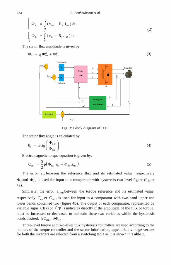
The components of stator flux can be estimated by,
A. Benbouhenni et al.
234
t
0
ssss
t
0
ssss
dt)i.Rv(
dt)i.Rv(
(2)
The stator flux amplitude is given by,
2s
2ss (3)
Fig. 3: Block diagram of DTC
The stator flux angle is calculated by,
s
ss arctg (4)
Electromagnetic torque equation is given by,
ssssem i.i.p2
3C (5)
The error between the reference flux and its estimated value, respectively
s and *s , is used for input to a comparator with hysteresis two-level figure (figure
4a).
Similarly, the error Cem between the torque reference and its estimated value,
respectively *emC et emC , is used for input to a comparator with two-band upper and
lower bands contained two (figure 4b). The output of each comparator, represented by
variable signs xCfl (or lCcp ) indicates directly if the amplitude of the flux(or torque)
must be increased or decreased to maintain these two variables within the hysteresis
bands desired, emC , s .
Three-level torque and two-level flux hysteresis controllers are used according to the
outputs of the torque controller and the sector information, appropriate voltage vectors
for both the inverters are selected from a switching table as it is shown in Table 1.

Speed regulator and hysteresis based on artificial intelligence techniques of...
235
Fig. 4: Hysteresis block
Table 1: Three-level DTC switching table with 24 sectors
Since none of the inverter switching vectors is able to generated the exact stator
voltage required to produce the desired changes in torque and flux, torque and flux
ripples compose a real problem in DTC induction motor drive [8].
5. DIRECT TORQUE CONTROL BASED ON
INTELLIGENCE ARTIFICIELS STRATEGY’S
The principle of artificial intelligence techniques direct torque control is similar to
traditional three-level DTC. However, the hysteresis controllers of torque and flux are
replaced by the fuzzy controller and neural networks. The PI controller of speed is
replaced by the fuzzy controller. The general structure of the IM with three-level DTC
24 sectors with artificial intelligence techniques is represented by figure 5.
5.1 Hysteresis controller of flux based on neural networks
Neural networks have self- adapting compatibilities which makes them well suited
to handle non-linarites, uncertainness and parameter variations. A multilayer feed
forward neural network constructs a global approximations to non- linear input-output
mapping. Neural networks are capable of generalization in regions of the input space,

A. Benbouhenni et al.
236
where little or no training data are available [9]. The structure of the proposed neural
networks used in this paper, is shown in figure 6.
Fig. 5: Three-level DTC with 24 sectors based on artificial
intelligence technics of an induction machine
Fig. 6: Structure of proposed artificial neural networks
Fig. 7:Structure of layer 1
Fig. 8: Structure of layer 2
The proposed neural networks have three layers, i.e. input layer, hidden layer and
the output layer. Input layer has 1 neuron, output layer has only one neuron and hidden
layer has 3 neurons.
5.2 Hysteresis controller of couple and PI controller based on fuzzy
Fuzzy logic is recently getting increasing emphasis in drive control applications.
Recent years, fuzzy logic control has found many applications in the past two decades.
This is so largely increasing because fuzzy logic control has the capability to control
Speed regulator and hysteresis based on artificial intelligence techniques of...
237
nonlinear uncertain systems even in the case where no mathematical model is available
for the control system [8].
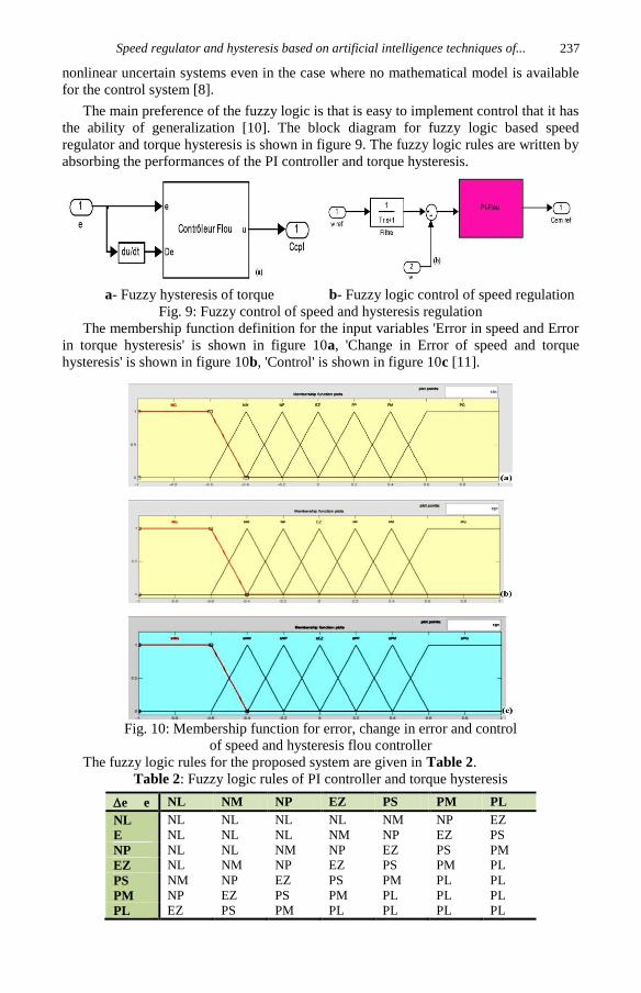
The main preference of the fuzzy logic is that is easy to implement control that it has
the ability of generalization [10]. The block diagram for fuzzy logic based speed
regulator and torque hysteresis is shown in figure 9. The fuzzy logic rules are written by
absorbing the performances of the PI controller and torque hysteresis.
a- Fuzzy hysteresis of torque b- Fuzzy logic control of speed regulation
Fig. 9: Fuzzy control of speed and hysteresis regulation
The membership function definition for the input variables 'Error in speed and Error
in torque hysteresis' is shown in figure 10a, 'Change in Error of speed and torque
hysteresis' is shown in figure 10b, 'Control' is shown in figure 10c [11].
Fig. 10: Membership function for error, change in error and control
of speed and hysteresis flou controller
The fuzzy logic rules for the proposed system are given in Table 2.
Table 2: Fuzzy logic rules of PI controller and torque hysteresis
e e NL NM NP EZ PS PM PL
NL NL NL NL NL NM NP EZ
E NL NL NL NM NP EZ PS
NP NL NL NM NP EZ PS PM
EZ NL NM NP EZ PS PM PL
PS NM NP EZ PS PM PL PL
PM NP EZ PS PM PL PL PL
PL EZ PS PM PL PL PL PL

A. Benbouhenni et al.
238
6. SIMULATION RESULTS AND DISCUSSION
The direct torque control with 24 sectors of an IM is implemented with simulation
tools of Matlab. The speed regulator is used as classical PI, PI-flou separately. The
hysteresis controllers are used as neural hysteresis and fuzzy hysteresis. The
performance analysis is done with speed, torque, flux, and current. The dynamic
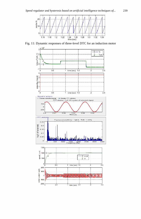
performance of the three-level DTC with 24 sectors of an induction motor is shown in
figure 11.
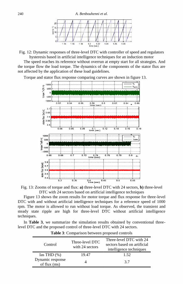
The dynamic performance of the three-level DTC with 24 sectors based on artificial
intelligence techniques for the induction motor is shown in figure 12.
Speed regulator and hysteresis based on artificial intelligence techniques of...
239
Fig. 11: Dynamic responses of three-level DTC for an induction motor
A. Benbouhenni et al.
240
Fig. 12: Dynamic responses of three-level DTC with controller of speed and regulators
hysteresis based in artificial intelligence techniques for an induction motor
The speed reaches its reference without overrun at empty start for all strategies. And
the torque flow the load torque. The dynamics of the components of the stator flux are
not affected by the application of these load guidelines.
Torque and stator flux response comparing curves are shown in figure 13.
Fig. 13: Zooms of torque and flux: a) three-level DTC with 24 sectors, b) three-level
DTC with 24 sectors based on artificial intelligence techniques
Figure 13 shows the zoom results for motor torque and flux response for three-level
DTC with and without artificial intelligence techniques for a reference speed of 1000
rpm. The motor is allowed to run without load torque. As observed, the transient and
steady state ripple are high for three-level DTC without artificial intelligence
techniques.
In Table 3, we summarize the simulation results obtained by conventional three-
level DTC and the proposed control of three-level DTC with 24 sectors.
Table 3: Comparison between proposed controls
Control Three-level DTC
with 24 sectors
Three-level DTC with 24
sectors based on artificial
intelligence techniques
Ias THD (%) 19.47 1.52
Dynamic response
of flux (ms) 4 3.7
Speed regulator and hysteresis based on artificial intelligence techniques of...
241
It can be seen that three-level DTC with 24 sectors based on artificial intelligence
techniques THD% is low as compare to conventional three-level DTC.
7. CONCLUSION The present paper has presented a sensor less speed three-level DTC drive 24 sectors
with artificial intelligence techniques applied to an IM is presented, fuzzy logic and
neural networks. This techniques determinates the desired amplitude of torque, flux
hysteresis band and speed controller.
It is shown that the flux and torque responses under steady state condition. The main
advantage is the improvement of torque and flux ripple characteristics at low speed
region, this provides an opportunity for motor operation under minimum switching loss
and noise.
APPENDIX The parameters of 3 phase induction machine employed for simulation purpose is
given below:
Table 4: Implementation parameters
Parameters Values
Nominal power 1 MW
Line to line voltage 791 V
Frequency 60 Hz
Stator resistance 0.228
Stator inductance 0.0084 H
Rotor resistance 0.332
Rotor inductance 0.0082 H
Mutual inductance 0.0078 H
Inertia 20 kg.m2
Friction 0.008 Nms
Number of poles 3
REFERENCES
[1] F. Benessek, W. Bourbia and B. Bensaker, 'Flatness Based non Linear Sensorless
Control of Induction Motor Systems', International Journal of Power Electronics and
Drive System, 'IJPEDS', Vol. 7, N°1, pp. 265 - 278, 2016.
[2] C. El Mehdi, M. Ahmed, M. Abdelkader and G. Abderrahmane, 'Sensorless Direct
Torque Control of Induction Machine with MRAS Speed Estimator', Computer
Science and Engineering, Vol. 3, N°1, pp. 8 - 13, 2013.
[3] S. a/I Ramahlingam, A. Bin Jidir, T. Sutikno and L.L. Raj, 'Improvise 3-Level DTC
of Induction Machine using Constant Switching Frequency Method by Utilizing
Multiband Carrier', International Journal of Power Electronics and Drive System,
'IJPEDS', Vol. 7, N°3, pp. 638 - 647, 2016.
[4] B. Naas, L. Nezli, B. Naas, M.O. Mahmoudi and M. Elbar, 'Direct Torque Control
Based Three Level Inverter-Feed Double Star Permanent Magnet Synchronous
Machine', Energy Procedia, Vol. 18, pp. 521 - 530, 2012.
[5] E. Benyoussef, A. Meroufel and S. Barkat, 'Three-Level DTC Based on Fuzzy Logic
and Neural Network of Sensorless DSSM Using ExtendeKalmanFiltre', International
Journal of Power Electronics and Drive System, 'IJPEDS', Vol. 5, N°4, pp. 453 -
463, 2015.

A. Benbouhenni et al.
242
[6] B. Sebti, 'Commande par DTC d’un Moteur Asynchrone , Apport des Réseaux de
Neurones', Mémoire de Magister, Université de Batna, 2013.
[7] E.O.D. Aissa, 'Etude de Stratégies De Commande pour la Régulation des Courants
de la Machine Asynchrone', Mémoire de Master Académique, université de
KasdiMerbah, Ouargla. 2013.
[8] A. Idir and M. Kidouche, 'Direct Torque Control of Three Phase Induction Motor
Drive Using Fuzzy Logic Controllers for Low Torque Ripple', Proceedings
Engineering & Technology, Vol. 2, pp. 78 - 83, 2013.
[9] N. Vahdatifar, Ss. Mortazavi and R. Kianinezhad, 'Neural Network Based Predictive
DTC Algorithm for Induction Motors', International Journal of Computer, Electrical,
Automation, Control and Information Engineering, Vol. 4, N°11, 2011.
[10] Z. Boudjema, A. Meroufel, E. Bounadja and Y. Djerriri, 'Nonlinear Control of a
Doubly Fed Induction Generator Supplied by a Matrix Converter for Wind Energy
Conversion Systems', Journal of Electrical Engineering, 'JEE', Vol. 13, N°4, pp. 60
- 68, 2014.
[11] M. Abdelhafidh, 'Stratégies de Commande DTC-SVM et DPC Appliquées à une
MADA utilisée pour la Production d’Energie Eolienne', Thèse de Doctorat, Ecole
Nationale Polytechnique, Alger, 2014