speed of light 12
TRANSCRIPT

8/3/2019 Speed of Light 12
http://slidepdf.com/reader/full/speed-of-light-12 1/32
Galileo
Through much of history, those few who thought tospeculate on the velocity of light considered it to beinfinite. One of the first to question this assumption was
the great Italian physicist Galileo, who suggested amethod for actually measuring the speed of light.
The method was simple. Two people, call them A and B,take covered lanterns to the tops of hills that are separatedby a distance of about a mile. First A uncovers herlantern. As soon as B sees As light, she uncovers herown lantern. By measuring the time from when Auncovers her lantern until A sees Bs light, then dividingthis time by twice the distance between the hill tops, thespeed of light can be determined.
However, the speed of light being what it is, and humanreaction times being what they are, Galileo was able todetermine only that the speed of light was far greater thancould be measured using his procedure. Although Galileowas unable to provide even an approximate value for thespeed of light, his experiment set the stage for laterattempts. It also introduced an important point: to measuregreat velocities accurately, the measurements mustbe made over a long distance.
Römer
The first successful measurement of the velocity of light
was provided by the Danish astronomer Olaf Römer in1675. Römer based his measurement on observations ofthe eclipses of one of the moons of Jupiter. As this moonorbits Jupiter, there is a period of time when Jupiter liesbetween it and the Earth, and blocks it from view. Römernoticed that the duration of these eclipses was shorterwhen the Earth was moving toward Jupiter than when theEarth was moving away. He correctly interpreted thisphenomena as resulting from the finite speed of light.
Geometrically the moon is always behind Jupiter for thesame period of time during each eclipse. Suppose,
however, that the Earth is moving away from Jupiter. Anastronomer on Earth catches his last glimpse of the moon,not at the instant the moon moves behind Jupiter, but onlyafter the last bit of unblocked light from the moon reacheshis eyes. There is a similar delay as the moon moves outfrom behind Jupiter but, since the Earth has moved
farther away, the light must now travel a longer distanceto reach the astronomer. The astronomer therefore sees aneclipse that lasts longer than the actual geometricaleclipse. Similarly, when the Earth is moving towardJupiter, the astronomer sees an eclipse that lasts a shorterinterval of time.
From observations of these eclipses over many years,Römer calculated the speed of light to be 2.1 x 10⁸ m/

8/3/2019 Speed of Light 12
http://slidepdf.com/reader/full/speed-of-light-12 2/32
sec. This value is approximately 1/3 too slow due to aninaccurate knowledge at that time of the distancesinvolved. Nevertheless, Römers method providedclear evidence that the velocity of light was notinfinite, and gave a reasonable estimate of its truevaluenot bad for 1675.
Fizeau
The French scientist Fizeau, in 1849, developed aningenious method for measuring the speed of lightover terrestrial distances. He used a rapidly revolvingcogwheel in front of a light source to deliver the lightto a distant mirror in discrete pulses. The mirrorreflected these pulses back toward the cogwheel.Depending on the position of the cogwheel when apulse returned, it would either block the pulse of lightor pass it through to an observer.
Fizeau measured the rates of cogwheel rotation thatallowed observation of the returning pulses for carefullymeasured distances between the cogwheel and the mirror.Using this method, Fizeau measured the speed of light tobe 3.15 x 10⁸ m/sec. This is within a few percent of thecurrently accepted value.
Foucault
Foucault improved Fizeaus method, using a rotatingmirror instead of a rotating cogwheel. (Since this is themethod you will use in this experiment, the details will bediscussed in considerable detail in the next section.) As
mentioned, Michelson used Foucaults method to producesome remarkably accurate measurements of the velocityof light. The best of these measurements gave a velocityof 2.99774 x 10⁸ m/sec. This may be compared to thepresently accepted value of 2.99792458 x 10⁸ m/sec.
2

8/3/2019 Speed of Light 12
http://slidepdf.com/reader/full/speed-of-light-12 3/32
012-07135ASpeed of Light
MF(Fixed Mirror)MR
(Rotating Mirror)L2 Beamsplitter L1sLaserMeasuringMicroscopes´The Foucault MethodFigure 1: Diagram of the Foucault Method
A Qualitative Description
In this experiment, you will use a method for measuring
the speed of light that is basically the same as thatdeveloped by Foucault in 1862. A diagram of the experimentalsetup is shown in Figure 1, above.
With all the equipment properly aligned and with therotating mirror stationary, the optical path is as follows.The parallel beam of light from the laser is focused to apoint image at point s by lens L1. Lens L2 is positioned sothat the image point at s is reflected from the rotatingmirror MR, and is focused onto the fixed, spherical mirrorMF. MF reflects the light back along the same path toagain focus the image at point s.
In order that the reflected point image can be viewedthrough the microscope, a beam splitter is placed in theoptical path, so a reflected image of the returning light isalso formed at point s´.
Now, suppose MR is rotated slightly so that the reflectedbeam strikes MF at a different point. Because of thespherical shape of MF, the beam will still be reflecteddirectly back toward MR. The return image of the sourcepoint will still be formed at points s and s´. The onlysignificant difference in rotating MR by a slight amount isthat the point of reflection on MF changes.
Now imagine that MR is rotating continuously at a veryhigh speed. In this case, the return image of the sourcepoint will no longer be formed at points s and s´. This isbecause, with MR rotating, a light pulse that travels fromMR to MF and back finds MR at a different angle when itreturns than when it was first reflected. As will be shownin the following derivation, by measuring the displacementof the image point caused by the rotation of MR, thevelocity of light can be determined.
A Quantitative Description
In order to use the Foucault method to measure the speedof light, its necessary to determine a precise relationshipbetween the speed of light and the displacement of the

8/3/2019 Speed of Light 12
http://slidepdf.com/reader/full/speed-of-light-12 4/32
image point. Of course, other variables of the experimentalsetup also affect the displacement. These include:
the rate of rotation of MR the distance between MR and MF
the magnification of L2, which depends on thefocal length of L2 and also on the distances between L2, L1, and MF.Each of these variables will show up in the final expressionthat we derive for the speed of light.
3

8/3/2019 Speed of Light 12
http://slidepdf.com/reader/full/speed-of-light-12 5/32
Speed of Light 012-07135A
To begin the derivation, consider a beam of light leavingthe laser. It follows the path described in the qualitativedescription above. That is, first the beam is focused to apoint at s, then reflected from M to M and back to M
R.RF,
The beam then returns through the beamsplitter, and isrefocused to a point at point s´, where it can be viewedthrough the microscope. This beam of light is reflectedfrom a particular point on MF. As the first step in thederivation, we must determine how the point of reflectionon MF relates to the rotational angle of M
R.
Figure 2a shows the path of the beam of light, from thelaser to MF, when MR is at an angle q. In this case, theangle of incidence of the light path as it strikes MR is also
q and, since the angle of incidence equals the angle ofreflection, the angle between the incident and reflectedrays is just 2q. As shown in the diagram, the pulse oflight strikes MF at a point that we have labeled S.Figure 2b shows the path of the pulse of light if it leavesthe laser at a slightly later time, when MR is at an angleq1 = q + Dq. The angle of incidence is now equal toq1 = q + Dq, so that the angle between the incident andreflected rays is just 2q1 = 2(q + Dq). This time we label
the point where the pulse strikes MF as S1. If we define Das the distance between MF and MR, then the distancebetween S and S1 can be calculated:
S1 - S = D(2q1 - 2q) = D[2(q + Dq) - 2q] = 2DDq (EQ1)
Figure 2a: When MR is at angle q, thelaser beam is reflected to point S on MF.MFSqq2qLaserqMRFigure 2b: When MR is at angle q1, thelaser beam is reflected to point S1 on MF.
qDqq1 = q+Dqq+Dqq+Dq2(q+Dq)S1Figure 2 a,b: The Reflection Point on MF
In the next step in the derivation, it is helpful to think of asingle, very quick pulse of light leaving the laser. SupposeMR is rotating, and this pulse of light strikes MRwhen it is at angle q, as in Figure 2a. The pulse will thenbe reflected to point S on MF. However, by the time thepulse returns to MR, MR will have rotated to a new angle,
say angle q1. If MR had not been rotating, but hadremained stationary, this returning pulse of light would berefocused at point s. Clearly, since MR is now in a

8/3/2019 Speed of Light 12
http://slidepdf.com/reader/full/speed-of-light-12 6/32
different position, the light pulse will be refocused at adifferent point. We must now determine where that newpoint will be.
The situation is very much like that shown in Figure 2b,with one important difference: the beam of light that isreturning to MR is coming from point S on MF, instead of
from point S1. To make the situation simpler, it is convenientto remove the confusion of the rotating mirror andthe beam splitter by looking at the virtual images of thebeam path, as shown in Figure 3.
DSDsDSD B ADs'L2MRMF
s1sBeamsplitterVirtualimage ofMFS1SSS1Figure 3: Analyzing the Virtual ImagesThe critical geometry of the virtual images is the same asfor the reflected images. Looking at the virtual images,
the problem becomes a simple application of thin lensoptics. With MR at angle q1, point S1 is on the focal axisof lens L2. Point S is in the focal plane of lens L2, but it isa distance DS = S1 - S away from the focal axis. Fromthin lens theory, we know that an object of height DS inthe focal plane of L2 will be focused in the plane of points with a height of (-i/o)DS. Here i and o are the distancesof the lens from the image and object, respectively, andthe minus sign corresponds to the inversion of the image.As shown in Figure 3, reflection from the beam splitterforms a similar image of the same height.
4

8/3/2019 Speed of Light 12
http://slidepdf.com/reader/full/speed-of-light-12 7/32
012-07135A Speed of Light
Therefore, ignoring the minus sign since we arentconcerned that the image is inverted, we can write anexpression for the displacement (Ds´) of the imagepoint:
D s¢ =D s =(i/o)D S = DA+B D S (EQ2)
Combining equations 1 and 2, and noting that
DS = S1 - S, the displacement of the image pointrelates to the initial and secondary positions of MR bythe formula:2DA Dq
D s¢ =(EQ3)
D +B
The angle Dq depends on the rotational velocity of MRand on the time it takes the light pulse to travel backand forth between the mirrors MR and MF, a distanceof 2D. The equation for this relationship is:
1Dw
Dq =(EQ4)
c
where c is the speed of light and w is the rotationalvelocity of the mirror in radians per second. (2D/cis the time it takes the light pulse to travel from MRto MF and back.)
Using equation 4 to replace Dq in equation 3 gives:
4AD2w
(EQ5)
D s¢ =
c(D +B)
Equation 5 can be rearranged to provide our finalequation for the speed of light:
4AD2w
c =(EQ6)
(D +B)D s¢
where:c = the speed of lightw = the rotational velocity of the rotating mirror (MR)

8/3/2019 Speed of Light 12
http://slidepdf.com/reader/full/speed-of-light-12 8/32
A = the distance between lens L2 and lens L1, minus
the focal length of L1B = the distance between lens L2 and the rotating mirror(MR)D = the distance between the rotating mirror (MR) and
the fixed mirror (MF)
Ds´ = the displacement of the image point, as viewedthrough the microscope. (Ds´ = s1 - s; where s is theposition of the image point when the rotating mirror(MR) is stationary, and s1 is the position of the imagepoint when the rotating mirror is rotating with angularvelocity w.)Equation 6 was derived on the assumption that the imagepoint is the result of a single, short pulse of light from thelaser. But, looking back at equations 1-4, the displacementof the image point depends only on the difference in
the angular position of MR in the time it takes for the lightto travel between the mirrors. The displacement does notdepend on the specific mirror angles for any given pulse.
If we think of the continuous laser beam as a series ofinfinitely small pulses, the image due to each pulse willbe displaced by the same amount. All these imagesdisplaced by the same amount will, of course, result in asingle image. By measuring the displacement of thisimage, the rate of rotation of MR, and the relevantdistances between components, the speed of light can bemeasured.
5

8/3/2019 Speed of Light 12
http://slidepdf.com/reader/full/speed-of-light-12 9/32
Speed of Light012-07135A
The Equipment
What You Need to Measure the Speed ofLight
In order to measure the speed of light as described in thismanual, you will need all the items listed below (seeFigure 4). If you have an OS-9261 Complete Speed ofLight Apparatus, everything is included. If you have theOS-9262 Basic Speed of Light Apparatus or the OS9263AHigh Speed Rotating Mirror, you will needadditional components, as listed, to make the measurement.
The OS-9261 Complete Speed of Light Apparatusincludes:
OS-9262 Basic Speed of Light Apparatus, whichincludes: OS-9263A High Speed Rotating Mirror Assembly Fixed Mirror Measuring Microscope SE-9367 0.5 mW He-Ne Laser OS-9103 One-Meter Optics Bench
OS-9172 Laser Alignment Bench OS-9142 Optics Bench Couplers OS-9133 Lens (48 mm FL) OS-9135 Lens (252 mm FL) OS-9109 Calibrated Polarizers (2) OS-9107 Component Holders (3) OS-8514 Laser Adapter Kit Alignment Jigs (2) Part Number 648-02230OS-9262 Basic Speed of Light ApparatusPASCO scientificMODEL OS-9263HIGH SPEED ROTATING MIRRORCAUTIONALLOW MOTOR TO STOPBEFORE CHANGING DIRECTIONMIRROR ROTATION DI RECTIONCCW CW
STOPSTOP MOTORIF LIT MORE

8/3/2019 Speed of Light 12
http://slidepdf.com/reader/full/speed-of-light-12 10/32
THAN 5 SEC.PUSH FORMAX REV/SEC60 SEC LIMITADJUSTREV/SEC0153
OS-9263A High Speed Rotating Mirror Assembly MeasuringMicroscopeFixed MirrorOS-9133 Lens (48 mm FL), andOS-9135 Lens (252 mm FL)OS-9103 One-Meter Optics BenchSE-9367 0.5 mW He-Ne LaserOS-8514 Laser Adapter KitOS-9142 Optics BenchCouplersOS-9109Calibrated
Polarizers (2)OS-9107ComponentHolders (3)AlignmentJigs (2)Figure 4: Equipment Included with the OS-9261A Complete Speed of Light Apparatus
6

8/3/2019 Speed of Light 12
http://slidepdf.com/reader/full/speed-of-light-12 11/32
012-07135A Speed of Light
About the Equipment
1. High Speed Rotating Mirror AssemblyThe High Speed Rotating Mirror comes with its own
power supply and digital display. The mirror is flat towithin 1/4 wavelength. Its supported by high speed ballbearings, mounted in a protective housing, and drivenby a DC motor with a drive belt. A plastic lock-screwlets you hold the mirror in place during the alignmentprocedure.
An optical detector and the digital display providemeasurements of mirror rotation to within 0.1% or 1 rev/sec. The display and the controls for mirror rotation areon the front panel of the power supply. Rotation isreversible and the rate is continuously variable from 100
to 1,000 rev/sec. In addition, holding down the MAXREV/SEC button will bring the rotation speed quickly toits maximum value at approximately 1,500 rev/sec.
ä CAUTION: Before turning on the motor forthe rotating mirror, carefully read the cautionarynotices in the section of this manual entitledMaking the Measurement.2. Measuring MicroscopeThe 90X microscope is mounted on a micrometer stagefor precise measurements of the displacement of theimage point. Measurements are most easily made byvisually centering the image point on the microscope
cross-hairs before and after the displacement. By notingthe change in the micrometer setting, the displacementcan be resolved to within 0.005 mm.
To focus the cross-hairs, slide the eyepiece up or down inthe microscope. To focus the microscope, loosen thelock-screw on the side of the mounting tube and slide themicroscope up or down within the tube.
With the lock-screw loosened, the microscope can also beremoved from the mounting tube. This can be helpfulwhen you are trying to locate the image point. A piece oftissue paper placed over the tube provides a screen thatallows you to view the point without focusing the microscope.
In addition to the microscope and micrometer, themicrometer stage also contains the beamsplitter. Thelever on the side of the stage is used to adjust the angle ofthe beamsplitter. When the lever points directly down,the beamsplitter is at a forty-five degree angle.
3. Fixed MirrorThe Fixed Mirror is a spherical mirror with a radius ofcurvature of 13.5 meters. It is mounted to a stand and has
separate x and y alignment screws.
4. OS-9103 Optics Bench

8/3/2019 Speed of Light 12
http://slidepdf.com/reader/full/speed-of-light-12 12/32
The 1.0 meter long Optics Bench provides a flat, levelsurface for aligning the optical components. The bench isequipped with a one meter scale, four leveling screws,and a magnetic top surface. The "fence", a raised edge onthe back of the bench, provides a guide for aligningcomponents along the optical axis.
5. SE-9367 Laser with the OS-9172 Alignment BenchThe 0.5 mW, TEM00 mode, random polarization laser hasan output wavelength of 632.8 nm. The Alignment Benchattaches to the Optics Bench for precise, stable positioningof the laser.
6. Alignment Jigs (2)These jigs mount magnetically to the Optics Bench.Each has a 2 mm diameter hole that is used to align thelaser beam.
7. Optical Components
The use of the lenses and polarizers is described in theSetup and Alignment section of the manual.
7

8/3/2019 Speed of Light 12
http://slidepdf.com/reader/full/speed-of-light-12 13/32
Speed of Light 012-07135A
Setup and Alignment
The following alignment procedure is tailored for
those using the OS-9261A Complete Speed of LightApparatus. For those using only some of the componentsin the complete system, the general procedure isthe same, though the details depend on the opticalcomponents used.
ä IMPORTANT: Proper alignment is critical,not only for getting good results, but for gettingany results at all. Please follow this alignmentprocedure carefully. Allow yourself about threehours to do it properly the first time. Once youhave set up the equipment a few times, you may
find that the alignment summary at the end ofthis section is a helpful guide.For reference as you set up the equipment, Figure 5shows the approximate positioning of the componentswith respect to the metric scale on the side of the OpticsBench. The exact placement of each component dependson the position of the Fixed Mirror (MF) and must bedetermined by following the steps of the alignmentprocedure described below.
All component holders, the Measuring Microscope, andthe Rotating Mirror Assembly should be mounted flushagainst the fence of the Optics Bench (Figure 6). This
will insure that all components are mounted at rightangles to the beam axis.
Figure 6:Placing ComponentsFlush Against the Fencefor Proper Alignment
FenceFigure 7: Coupling the Optics Bench and theLaser Alignment BenchLaser and LaserAlignment BenchOptics BenchSideViewTopViewFour screwsincluded withBench CouplersBench CouplersFour levelingscrews from
Optics Benchand LaserAlignment

8/3/2019 Speed of Light 12
http://slidepdf.com/reader/full/speed-of-light-12 14/32
Bench (usetwo, save two)17 cmLeveling Screw62.2 cmL2 (252 mmfocal length)
Optics BenchL1 (48 mmfocal length) LaserLaser AlignmentBenchPolarizers93.0 cmLevelingScrewsMeasuringMicroscope82.0 cm*
Rotating MirrorAssembly(MR)* Earlier units with themicroscope offset to the rightof center on its base shouldbe set at 81.0 cm.Figure 5: Equipment Alignment
8

8/3/2019 Speed of Light 12
http://slidepdf.com/reader/full/speed-of-light-12 15/32
012-07135ASpeed of Light
17 cmMR Alignment JigsLeveling Screws: Use to aim the laser
beam through the alignment jigs.Figure 8: Using the Alignment Jigs to Align the Laser
To Set up and Align the Equipment:
1.Place the Optics Bench on a flat, level surface.2.Place the Laser, mounted on the Laser AlignmentBench, end-to-end with the Optics Bench, at theend corresponding to the 1-meter mark of the metricscale.
3.Use the Bench Couplers and the provided screws toconnect the Optics Bench and the Laser AlignmentBench. Details are shown in Figure 7. Do not yettighten the screws holding the Bench Couplers.ä Note that the leveling screws must be removedfrom the Optics Bench and from the Laser AlignmentBench to attach the Bench Couplers. Two ofthe removed leveling screws are then inserted intothe threaded holes in the Bench Couplers and areused for leveling.4.Mount the Rotating Mirror Assembly on the opposite
end of the bench. Be sure the base of the assembly isflush against the fence of the Optics Bench and alignthe front edge of the base with the 17 cm mark on themetric scale of the Optics Bench (see Figure 8).5.The laser must be aligned so the beam strikes the centerof the Rotating Mirror (MR). Two alignment jigsare provided for this purpose. Place one jig at eachend of the Optics Bench as shown in Figure 8, withthe edges flush against the fence of the bench. Whenproperly placed, the holes in the jigs define a straightline that is parallel to the axis of the Optics Bench.6.Turn on the Laser.ä CAUTION: Do not look into the laser beam,either directly or as it reflects from either mirror.Also, when arranging the equipment, be sure thebeam path does not traverse an area where someonemight inadvertently look into the beam.7.Adjust the position of the front of the laser so thebeam passes directly through the hole in the firstjig. (Use the two front leveling screws to adjust theheight. Adjust the position of the laser on the LaserAlignment Bench to adjust the lateral position.)
Then adjust the height and position of the rear ofthe laser so the beam passes directly through thehole in the second jig.

8/3/2019 Speed of Light 12
http://slidepdf.com/reader/full/speed-of-light-12 16/32
Hole in Alignment JigReflected laser beamPaperFigure 9: Aligning the Rotating Mirror (MR)
9

8/3/2019 Speed of Light 12
http://slidepdf.com/reader/full/speed-of-light-12 17/32
Speed of Light012-07135A
93.0 cmL1: Position L1 at 93.0 cm,then adjust its position
on the holder to centerthe beam on MR.Rotating Mirror (MR)Figure 10: Positioning and Aligning L1
8.To fix the laser in position with respect to the OpticsBench, tighten the screws on the Bench Couplers.Then recheck the alignment of the laser.9.Align the Rotating Mirror. MR must be aligned sothat its axis of rotation is vertical and also perpendicular
to the laser beam. To accomplish this, removethe second alignment jig and then rotate MR so thatthe laser beam reflects back toward the hole in thefirst alignment jig (Figure 9). Be sure to use the reflectiveside of the mirror. It helps to tighten the lock-screw on the rotating mirror assembly just enough soMR holds its position as you adjust its rotation.If needed, use pieces of paper to shim between theRotating Mirror Assembly and the Optics Bench sothat the laser beam is reflected back through the holein the first jig.
10. Remove the first alignment jig.
11. Mount the 48 mm focal length lens (L1) on the OpticsBench so that the center line of the ComponentHolder is aligned with the 93.0 cm mark on the metricscale of the bench. Without moving the ComponentHolder, slide L1 as needed on the holder to centerthe beam on MR (see Figure 10). Notice that L1has spread the beam at the position of MR.12. Mount the 252 mm focal length lens (L2) on the OpticsBench so the center line of the ComponentHolder aligns with the 62.2 cm mark on the metricscale of the bench. As for L1 in step 11, adjust theposition of L2 on the Component Holder so that thebeam is again centered on MR.13.Place the Measuring Microscope on the Optics Benchso that the left edge of the mounting stage is aligned withthe 82.0 cm mark on the bench (see Figure 5). The leverthat adjusts the tilt of the beam splitter should be on thesame side as the metric scale of the Optics Bench.Position this lever so it points directly down.ä CAUTION: Do not look through the microscopeuntil the polarizers have been placed betweenthe laser and the beam splitter in step 19.
The beamsplitter will slightly alter the position of
the laser beam. Readjust L2 on the Component

8/3/2019 Speed of Light 12
http://slidepdf.com/reader/full/speed-of-light-12 18/32
Holder so the beam is again centered on M
R.14.Place the Fixed Mirror (MF) from 2 to 15 metersfrom MR, as shown in Figure 11. The angle between
the axis of the Optics Bench and a line from MR toMF should be approximately 12 degrees. (If it isgreater than 20-degrees, the reflected beam will beblocked by the Rotating Mirror enclosure.) Also besure that MF is not on the same side of the opticalbench as the micrometer knob, so you will be able tomake the measurements without blocking the beam.ä NOTE: Best results are obtained when MF is10 to 15 meters from MR. See Notes on Accuracynear the end of the manual.10

8/3/2019 Speed of Light 12
http://slidepdf.com/reader/full/speed-of-light-12 19/32
012-07135ASpeed of Light
MeasuringMicroscopes´
MF(Fixed Mirror)L2 Beamsplitter L1sMR(Rotating Mirror)ª 12° Laser2-15 MetersFigure 11: Positioning the Fixed Mirror (MF)
15.Position MR so the laser beam is reflected towardMF. Place a piece of paper in the beam path andwalk
the beam toward MF, adjusting the rotationof MR as needed.
16.Adjust the position of MF so the beam strikes it approximatelyin the center. Again, a piece of paper inthe beam path will make the beam easier to see.17.With a piece of paper still against the surface of MF,slide L2 back and forth along the Optics Bench tofocus the beam to the smallest possible point on MF.18.Adjust the two alignment screws on the back of MFso the beam is reflected directly back to the center of
MR. This step is best performed with two people:one adjusting MF, and one watching the beam positionat MR.19.Place the polarizers (attached to either side of asingle Component Holder) between the laser and L1.Begin with the polarizers at right angles to eachother, than rotate one until the image in the microscopeis bright enough to view comfortably.If you cant find the point image there are severalthings you can try:
Vary the tilt of the beamsplitter slightly (no morethan a few degrees) and turn the micrometer knob tovary the transverse position of the microscope untilthe image comes into view. Loosen the lock-screw on the microscope. As shownin Figure 13, remove the microscope and place a pieceof tissue paper over the tube to locate the beam. Adjustthe beamsplitter angle and the micrometer knob tocenter the point image in the tube of the microscope.
Slide the Measuring Microscope a centimeter or soin either direction along the axis of the Optics Bench.Be sure that the Microscope stays flush against the

8/3/2019 Speed of Light 12
http://slidepdf.com/reader/full/speed-of-light-12 20/32
fence of the Optics Bench. If this doesnt work, recheckthe alignment, beginning with step 1.20. Bring the cross-hairs of the microscope into focus bysliding the microscope eyepiece up and down.21. Focus the microscope by loosening the lock-screwand sliding the scope up and down. If the apparatusis properly aligned, you will see the point image
through the microscope. Focus until the imageis as sharp as possible.
Figure 13: Lookingfor the Beam Image
Lock-screwMicrometerknobTissuepaper
Lever foradjustingthebeamsplitterangle11
8/3/2019 Speed of Light 12
http://slidepdf.com/reader/full/speed-of-light-12 21/32
Speed of Light012-07135A
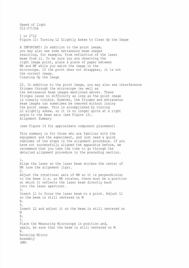
1 or 2°L2Figure 12: Turning L2 Slightly Askew to Clean Up the Image
ä IMPORTANT: In addition to the point image,you may also see some extraneous beam imagesresulting, for example, from reflection of the laserbeam from L1. To be sure you are observing theright image point, place a piece of paper betweenMR and MF while you watch the image in themicroscope. If the point does not disappear, it is notthe correct image.Cleaning Up the Image
22. In addition to the point image, you may also see interferencefringes through the microscope (as well as
the extraneous beam images mentioned above). Thesefringes cause no difficulty as long as the point imageis clearly visible. However, the fringes and extraneousbeam images can sometimes be removed without losingthe point image. This is accomplished by turningL2 slightly askew, so it is no longer quite at a rightangle to the beam axis (see Figure 12).Alignment Summary
(see Figure 14 for approximate component placement)
This summary is for those who are familiar with theequipment and the experiment, and just need a quick
reminder of the steps in the alignment procedure. If youhave not successfully aligned the apparatus before, werecommend that you take the time to go through thedetailed alignment procedure in the preceding section.
1.Align the laser so the laser beam strikes the center ofMR (use the alignment jigs).2.Adjust the rotational axis of MR so it is perpendicularto the beam (i.e. as MR rotates, there must be a positionat which it reflects the laser beam directly backinto the laser aperture).3.Insert L1 to focus the laser beam to a point. Adjust L1so the beam is still centered on MR.4.Insert L2 and adjust it so the beam is still centered onMR.5.Place the Measuring Microscope in position and,again, be sure that the beam is still centered on MR.
Rotating MirrorAssembly(MR)

8/3/2019 Speed of Light 12
http://slidepdf.com/reader/full/speed-of-light-12 22/32
17 cmLeveling Screw62.2 cmL2 (252 mmfocal length)Optics BenchL1 (48 mmfocal length) Laser
Laser AlignmentBenchPolarizers93.0 cmMeasuringMicroscope82.0 cm** Earlier units with themicroscope offset to the rightof center on its base shouldbe set at 81.0 cm.Leveling
ScrewsFigure 14: Equipment Alignment
12

8/3/2019 Speed of Light 12
http://slidepdf.com/reader/full/speed-of-light-12 23/32
012-07135ASpeed of Light
ä CAUTION: Do not look through the microscopeuntil the polarizers have been placed betweenthe laser and the beamsplitter.
If the spot you need to measure is significantly off-center,you can move it by adjusting the angle of the beamsplitter.
6.Position MF at the chosen distance from MR (2 - 15meters), so the reflected image from MR strikes thecenter of MF.7.Adjust the position of L2 to focus the beam to a pointon MF.
8.Adjust MF so the beam is reflected directly back ontoMR.9.Insert the polarizers between the laser and the beamsplitter.10. Focus the microscope on the image point.11. Remove polarizers.Alignment Hints
Once you have the microscope focused, it may still bedifficult to obtain a good spot. There may be several other
lights visible in the microscope besides the spot reflectedfrom the fixed mirror.
Stray interference patter.
Off-center spo.Stray spo.
The most common of these are stray interferencepatterns. These are caused by multiple reflections fromthe surfaces of the lenses, and may be ignored. Ifnecessary, you may be able to eliminate them byangling the lenses 1 2°.
Stray Spots are most often caused by reflections off thewindow of the rotating mirror housing. To determinewhich spot is the one you must measure, block the beampath between the rotating mirror and the fixed mirror. Therelevant spot will disappear.
Enlongated spot with fringe.
Another common problem is a spot that is stretched

8/3/2019 Speed of Light 12
http://slidepdf.com/reader/full/speed-of-light-12 24/32
with no easily discernible maxima. Check first to makesure that this is the spot you need by blocking thebeam path between the moving and fixed mirrors. If itis, then twist L2 slightly until the image coalesces intoa single spot.
Actual spo.
Bright ban.
Once the mirror begins to rotate, it is safe to look into themicroscope without the polarizers. You will notice thatyour carefully aligned pattern has changed: now the entirefield is covered with a random interference pattern, andthere is a bright band down the center of the field. Ignorethe interference pattern; theres nothing you can do aboutit anyway. The band is the image of the laser when, once
each rotation, the mirror reflects it into the microscopebeamsplitter. This is also unavoidable.
Your actual spot will probably be just to one side of thebright band. You can check for it by blocking andunblocking the beam path between the rotating mirror andfixed mirror and watching to see what disappears.
If you aligned everything perfectly, the spot will behidden by the bright band; in this case, make sure that youhave a spot when the rotating mirror is fixed and isreflecting the laser to the fixed mirror. If you do have thecorrect spot under stationary conditions, then misalign the
fixed mirror very slightly (0.004° or less) around thehorizontal axis. This will bring the actual spot out fromunder the bright band.
13

8/3/2019 Speed of Light 12
http://slidepdf.com/reader/full/speed-of-light-12 25/32
Speed of Light012-07135A
Making the Measurement
The speed of light measurement is made by rotating themirror at high speeds and using the microscope andmicrometer to measure the corresponding deflection ofthe image point. By rotating the mirror first in onedirection, then in the opposite direction, the total beamdeflection is doubled, thereby doubling the accuracy ofthe measurement.
.Importantto Protect the Rotating MirrorAssembly: Before turning on the motor, be sure the lock-
screw for the rotating mirror is completely loosened,so the mirror rotates freely by hand. Whenever the speed of the motor is accelerated,the red LED on the front panel of the motor controlbox will light up. As the speed stabilizes, thislight should go off. If it does not, turn off the motor.Something is interfering with the motor rotation.Check to be sure the lock-screw for MR isfully loosened. Never run the motor with the MAX REV/SECbutton pushed for more than one minute at a time,and always allow about a minute between runs forthe motor to cool off.
1.With the apparatus aligned and the beam image insharp focus (see the previous section), set the directionswitch on the rotating mirror power supply to CW,and turn on the motor. If the image was not in sharpfocus, adjust the microscope. You should also turn L2slightly askew (about 1 - 2°) to improve the image. Toget the best image you may need to adjust the microscopeand L2 several times. Let the motor warm up atabout 600 revolutions/sec for at least 3 minutes.2.Slowly increase the speed of rotation. Notice how thebeam deflection increases.3.Use the ADJUST knob to bring the rotational speedup to about 1,000 revolutions/sec. Then push theMAX REV/SEC button and hold it down. When therotation speed stabilizes, rotate the micrometer knobon the microscope to align the center of the beam imagewith the cross hair in the microscope that is perpendicularto the direction of deflection. Recordthe speed at which the motor is rotating, turn offthe motor, and record the micrometer reading.MF(Fixed Mirror)
MR(Rotating Mirror)L2 Beamsplitter L1s

8/3/2019 Speed of Light 12
http://slidepdf.com/reader/full/speed-of-light-12 26/32
LaserMeasuringMicroscopes´Figure 15: Diagram of the Foucault Method
14

8/3/2019 Speed of Light 12
http://slidepdf.com/reader/full/speed-of-light-12 27/32
012-07135ASpeed of Light
.NOTE:When reversing the direction of movement of
the micrometer carriage, there will always besome movement of the micrometer knob beforethe carriage responds. Though this source oferror is small, it can be eliminated. Just adjust theinitial position of the micrometer stage so thatyou always turn the micrometer knob in thesame direction as you adjust it.
5.The following equation was derived earlier in themanual:4AD2w
c =
(D + B) D s¢
When adjusted to fit the parameters just measured,it becomes:
8p AD2(Rev/sec+ Rev/sec)
cw ccw
c =
(D + B)(s¢ s¢ )
cw cw
Reverse the direction of the mirror rotation byswitching the direction switch on the power supplyto CCW. Allow the mirror to come to a completestop before reversing the direction. Then repeatyour measurement as in step 3.
.NOTES:-When the mirror is rotated at 1,000 rev/sec ormore, the image point will widen in the directionof displacement. Position the microscopecross-hair in the center of the resulting image.
-The micrometer on the Measuring Microscopeis graduated in increments of 0.01 mm for thebeam deflections.
Use this equation, along with the diagram in Figure15, to calculate c, the speed of light. (To measure A,
measure the distance between L1 and L2, then subtractthe focal length of L1, 48 mm.)

8/3/2019 Speed of Light 12
http://slidepdf.com/reader/full/speed-of-light-12 28/32
15

8/3/2019 Speed of Light 12
http://slidepdf.com/reader/full/speed-of-light-12 29/32
Speed of Light 012-07135A
Notes on Accuracy and Maintenance
Accuracy
Precise alignment of the optical components and carefulmeasurement are, of course, essential for an accuratemeasurement using this equipment. Beyond this, themain factor affecting accuracy is the distance between thefixed and rotating mirrors.
As mentioned in the alignment procedure, the optimumdistance between MR and MF is from 10 to 15 meters.Within this range, accuracy within 5% is readily obtainable.If space is a problem, the distance between themirrors can be reduced to as little as 1 meter and proportional
reduction in accuracy will result.
In general, longer distances provide greater accuracy. M
R
rotates farther as the light travels between the mirrors, andthe image deflection is correspondingly greater. Greaterdeflections reduce the percentage of measurement error.
However, the optical components are designed foroptimal focusing of the image point at 13.5 meters (this isthe radius of curvature of MF). Image focusing is not a
significant problem as long as the distance between themirrors is within about 15 meters. At larger distances theintensity and focus of the image point begins to drop, andmeasurement and alignment are hampered.
Typical sample data taken in our lab gives values for cthat are within 1.5 - 2.5% of accepted values.
Maintenance
Regular maintenance for this equipment is minimal. Themirrors and lenses should be cleaned periodically.
ä IMPORTANT: All mirrors and lenses maybe cleaned with lens tissue, except the sphericalmirror (MF). It has a delicate aluminized frontsurface and should only be cleaned with alcoholand a soft cloth. Do not use any cleaning compoundthat contains ammonia (such as Windex);the ammonia will attack the aluminum surface.If problems arise with the rotating mirror assembly, suchas a broken drive belt, notify PASCO scientific. We donot recommend that you attempt to fix this equipmentyourself. (See the warranty and equipment return informationat the front of this manual.)
16

8/3/2019 Speed of Light 12
http://slidepdf.com/reader/full/speed-of-light-12 30/32
8/3/2019 Speed of Light 12
http://slidepdf.com/reader/full/speed-of-light-12 31/32
Technical Support
Feedback
If you have any comments about the product or manual,
please let us know. If you have any suggestions onalternate experiments or find a problem in the manual,please tell us. PASCO appreciates any customerfeedback. Your input helps us evaluate and improve ourproduct.
To Reach PASCO
For technical support, call us at 1-800-772-8700 (toll-freewithin the U.S.) or (916) 786-3800.fax: (916) 786-3292e-mail: [email protected]
web: www.pasco.com
Contacting Technical Support
Before you call the PASCO Technical Support staff, itwould be helpful to prepare the following information:
ä If your problem is with the PASCO apparatus,note:.Title and model number (usually listed on thelabel);.
Approximate age of apparatus;.A detailed description of the problem/sequence ofevents (in case you cant call PASCO right away,you wont lose valuable data);.If possible, have the apparatus within reach whencalling to facilitate description of individual parts..If your problem relates to the instruction manual,note:� Part number and revision (listed by month and yearon the front cover);� Have the manual at hand to discuss yourquestions.

8/3/2019 Speed of Light 12
http://slidepdf.com/reader/full/speed-of-light-12 32/32