speed-lift owner's manual - superior handling equipment, llc
TRANSCRIPT

1
Speed-Lift Owner’s Manual
TABLE OF CONTENTS
Installation Suggestions
Uploading from Carrier
Positioning for Efficiency
Electrical Hook-Up
Operating Instructions
Specifications
Models and Options
Maintenance Guidelines
Lubrication
Visual Checks
Operation Checks
Troubleshooting Analysis
Service Checks
Electrical Symptoms, Causes and Solutions
Hydraulic Symptoms, Causes and Solutions
Mechanical Symptoms, Causes and Solutions
Electrical Systems Drawing
Electrical Control Box

2
Hydraulic Systems Drawing
Mechanical Systems Drawing
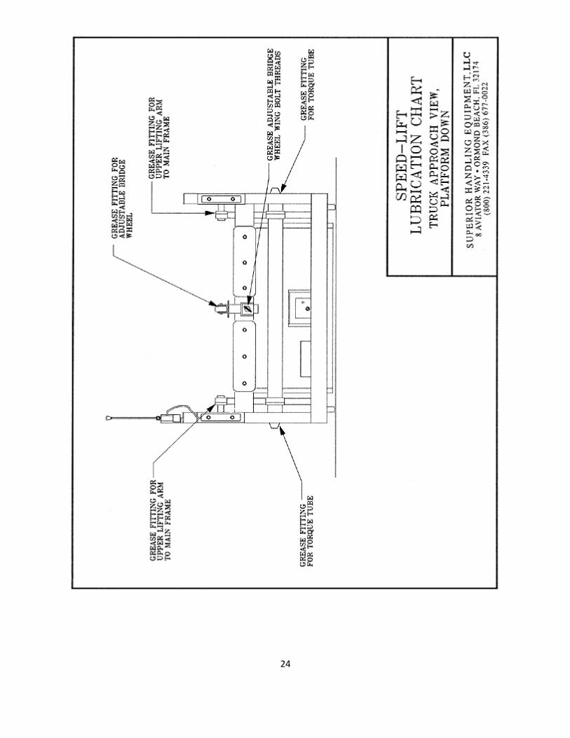
Lubrication Chart
Parts List
Operating Instructions, Cautions, Warnings and Danger Decals
Speed-Lift Right Side View, Platform Raised Decal Locations
Speed-Lift Top View, Platform Down Decal Locations
IMPORTANT
Please read and understand this manual prior to installation or operation of the Speed- Lift. If
you have any questions, call Superior Handling Equipment toll free at (800) 221-4339
immediately. Use this information for training all Speed-Lift operators
Planned Maintenance Program
Your Speed-Lift requires maintenance every four (4) months, or more often in extra harsh
environments and/or in very high volume applications, If your maintenance department is not
equipped or prefers not to do the Planned Maintenance Program every four months, make
arrangements with a good outside contractor to do so, or call Superior Handling Equipment, LLC.
at (800) 221-4339 for assistance.

3
Installation Suggestions
Unloading from Carrier
All models of the Speed-Lift are shipped on flat-bed trucks. Arrangements must be made for
unloading the lift from the carrier’s flat-bed truck at the delivery location. Any of the following
techniques may be used:
1. A large heavy-duty tow truck equipped with an extendable hydraulic boom which can put
the lifting hook(s) 11 feet or higher above the center of a flat bed truck will be more than
adequate for off-loading any Speed-Lift at delivery. Smaller tow trucks with sufficient lifting capacity for various size lifts may be used as long as the load is lifted from the
center and is balanced. One tow truck on each side of the flat-bed truck may also be used
to hoist the Speed-Lift clear, then remove the flat-bed from beneath, and carefully lower the unit evenly to the ground. Use only quality towing companies with knowledgeable
employees.
2. Forklifts, one positioned on each side of the flat-bed delivery truck may also be used to lift
the Speed-Lift clear while the truck is driven out from under it, then the dock lift can be lowered evenly to ground level, where it may be moved on its own wheels into position for
use.
3. A boom crane of sufficient capacity to safely handle the specified Speed-Lift weight may also be used for delivery carrier unloading, and is particularly useful when careful
positioning of assembled units in tight places, on raised pads, or inside building doors is
required. 4. Tilt bed wreckers are extremely useful for moving Speed-Lifts from one location to
another, but are not recommended for unloading lifts from flat-bed carrier semi-trucks
unless great care is taken by professionals to prevent a lift from rolling off the side of the
flat-bed before reaching the tilt bed truck.
Positioning for Efficiency
Designing each unloading/loading area for maximum efficiency is vital to long-term profitability. The Speed-Lift may be positioned outside or inside, permanently in one location, or mobile to be
moved from one spot to another. Should daily movement be necessary, it is recommended that
the unit be placed on smooth level concrete for easiest rolling. Larger lifts may be equipped with
tow bars for power assisted movement with tuggers, fork trucks, or trucks.
Position the Speed-Lift to minimize the distance employees must walk or travel on fork trucks as they unload. Eliminate rough surfaces, bumps, inclines or ramps and doorjams where possible
between the lift and the building entrance. Placing the Speed-Lift on the same ground level as
the truck usually is best because it permits smooth side to side alignment of the truck bridge and extra truck bumper clearance. When the lift is positioned 6” or more above the truck
approach level, a Lower Opening Bridge (LOB) and possibly an Extended Bridge (EB) option will
be needed.

4
Truck approaches to Speed-Lift may be improved for unloading purposes by raising or lowering
low or high points respectively, to correct a slanting or sloping truck. This is especially important when hand pallet jacks or carts are used. Ideally, trucks should be level from side to side and
from nose to rear door, or with a slight nose high condition of 6” to 8” or so. Position the Speed-
Lift on level or nearly level concrete pavement for best efficiency, greatest safety, and greatest
mobility should the lift need to be frequently moved.
Electrical Hook-Up
Speed-Lift motors and electrical controls are wired for 230 volt, 3 phase, AC power unless 208
volts or 480 volts is specified. The following amperages are required:
MODEL H.P. VOLTAGE
MOTOR AMPERAGE REQUIRED
BRANCH MAX CIRCUIT BREAKER
AMP. RATING MALE PLUG
# FEMALE CONNECTOR
#
SL-5000/6000 5 240 15 30 2721 2723
460 7.6 15 2431 2433
SL-8000 10 240 28 50 2721 2723
460 15 30 2431 2433
SL-10000 15 240 42 60 cs8364c cs8365c
460 21 30 2731 2733
SL-12000 20 240 54 100 460P9W 460C9W
thru SL-24000
460 27 50 2731 2733
A 30 foot, heavy-duty SO power cord complete with three phase twist-lock sockets and plugs
comes with each unit, except for E-Z install inside Speed-Lifts which have 15 foot power cords
ready to plug in or hard wire to your on/off switched circuit with breaker or fuse protection. Only
professionally qualified persons with proper authorization should work on this electrical hookup.
When positioning the power outlet, seek a location where traffic will not cross over the power cord when the docklift is in use. A switched circuit breaker box or on/off disconnect mounted
inside the building, on the side of the door nearest the Speed-Lift unloading position, will permit
good outlet positioning. A buried conduit housing the electric power lines may be used with any Speed-Lift which is fixed solidly in one position with ground, slab, surface, post support, or wall-
to-floor optional anchors.
Three phase motors may run forward or backward depending upon how they are
wired. Before the electrician leaves, check for proper motor rotation by moving the Speed-Lift control handle to raise the lift platform. If the motor runs and the platform rises, the
motor is wired properly. If the motor runs but the platform does not lift, the electrician should
reverse motor rotation by switching two of the hot wires. Do not move or switch the green
ground wire on the “L” shaped plug prong. Always switch off and “lock out” electric power before working on electrical systems. After connecting to the proper electric power, raise the

5
platform and remove the steel shipping block under each cylinder. This will permit the
platform to be lowered to the ground.
Operational Instructions
WARNING! Read and understand this Speed-Lift Owner’s Manual BEFORE attempting to use the Speed-Lift, or personal injury may result. If you have questions please call (800) 221-4339 at
any time, 24 hours a day. Thank you for making safety your highest priority.
WARNING! All operators must read and become familiar with all caution, warning, danger and information decals. The Speed-Lift is for use by authorized operators only who are over 18 years
of age, and who have learned these operating instructions.
Assist truck driver when positioning the truck for loading or unloading.
WARNING! When moving a Speed-Lift, stay clear of wheels and frame, then always crank down
stabilization jack pads securely before using the docklift to avoid personal injury.
WARNING! Turn electric power off at the switch or circuit breaker box before plugging in or
unplugging the lift with each use, to avoid personal injury from electric shock.
WARNING! USE PERSONNEL RESTRAINT BAR (PRBCC), SAFETY CHAIN (SC), OR AUTOMATED
FOLDING RAMP (AFR) WHEN PLATFORM IS ELEVATED TO AVOID PERSONAL INJURY.
WARNING! Operate with caution keeping away from moving parts at all times.
WARNING! Do not leave platform in a raised position. After a shipment or delivery is finished,
lower the platform to ground level and turn off the electric power. Do Not Go under a Raised
Platform for Any Reason unless safety blocking precautions to prevent accidental platform
lowering have been taken, or personal injury may result. Speed-Lifts may be blocked by placing hardwood or steel blocks under 2 or more cylinder rod ends and lowering the empty platform
until the weight of the unit is solidly supported by rod end blocks resting on the Speed-Lift
frame. The main control handle may also be "locked out" with a padlock to prevent unauthorized
use.

6
WARNING! Stand clear of bridge into truck when lowering of platform causes bridge to fold, or
raising platform causes bridge to open to avoid personal injury. Stand clear of and do not touch
Truck Bridge or Automated Folding Ramp when platform is being raised or lowered to avoid
injury.
Position Adjustable Height Bridge Wheel so that the bridge opens automatically onto the truck
floor, overlapping the truck floor 4” - 7” or more, as the platform is raised. The Adjustable
Bridge Wheel should not touch the underside of the level open bridge once the platform is raised to truck height because it is built to guide the bridge open at the correct height and not to
support the load. The Automatic Bridge or the optional Automated Folding Ramp should not be
touched during operation or personal injury may result.
WARNING! The Speed-Lift Truck Bridge MUST overlap the truck floor (or raised dock level if the
lift is used at a dock) by 4” - 7” or more to safely support loads being moved across the bridge. Failure to reposition the Speed-Lift or to reposition the truck to allow 4” - 7” of bridge
overlapping support from the truck floor (or dock surface) may result in personal injury.
Use smooth, gradual movements of the control valve handle to raise or lower the plat form
without sudden starts or stops. Do not pull, push, or hang onto control handles with excessive
force because handle bending or breakage may result.
WARNING! When two or more persons are operating the lift and moving loads independently of
the other, make certain the lift is raised or lowered to the proper height before moving a load
onto or from the platform to avoid personal injury. Always double check when moving a load
onto a raised platform to be certain that someone else has not moved or used the platform first.
Run motor/pump continuously during super cold weather (~1O° or colder) by turning “ON” the Energy Conservation System Bypass Switch located on the electric control box, during each use
when super cold weather slows the platform lowering speed noticeably. After Speed-Lift use is
completed, turn the motor off. Use the Cold Weather Energy Conservation System Bypass

7
“continuous run” feature only when it is needed during really cold weather, and only while the
truck is being unloaded/loaded.
Notify maintenance and repair service personnel for Speed-Lifts immediately when anything is
noticed which requires adjustment, repair, or replacement.
WARNING! Continued use of a lift which requires maintenance or repair may cause personal
injury. Make certain all repair needs are done promptly.
WARNING! When working after dark, use sufficient light to clearly see all areas of the Speed-
Lift, truck, and surrounding area to avoid injury.
DO YOU HAVE SAFETY RELATED QUESTIONS, COMMENTS, OR SUGGESTIONS? PLEASE
CALL (800) 221-4339 OR (386) 677-0004 IMMEDIATELY! Thank You For Making
Workplace Safety Your Highest Priority.
Specifications
Nine Load Capacities — Eleven Standard Platform Sizes
Notes:
1. Minimum lifting or lowering time is 7 seconds, to or from 50”, for all models listed above. 2. Maximum raised platform height is 58”, for all models.

8
3. Standard bridge and ramp length is 34”.
4. Due to constant innovation, specifications are subject to change without notice.
5. Patent rights for patents granted and pending apply.
Profit Boosting Options
EZ Install Inside Lifts (001) Personnel Restraint Bar (PRB) Platform Stops (PLTS) Surface Anchor Impact & Restraint System (SA)
Extended Bridges (EB) Automated Folding Ramp (AFR)
Step Bumper Protectors (SBP) Ground Anchor Impact and Restraint System (GA) Lower Opening Bridges (LOB) Dock-To-Ground Hydraulic Lock (DG) Vertical Bumper Extenders (VBE) Wall and Floor Anchors (WE) Minimum Opening Bridges (MOB) Frame Beyond Dock (FBD) Truck Restraint Adapters (TRA) Front Stabilization Jacks (FSJ) Side-Off Platforms (SOP - L or R) Hydrolic Ramp Winch (HRW) Light and Sign Communication Mast (LSC) Automatic Cart Stop Ramp (ACSR) Lateral Track Mobility (LTM) Flotation Plates (FP) Bumper Post Impact & Restraint System (PS)
Other Speed Lift Options are available to meet both your present and future needs. Whether inside, outside, fixed in one position or mobile, Speed-Lifts Offer The Total Docklift Value
YOU Expect... And Then Some!!!
QUESTIONS? PLEASE CALL 800-221-4339
New Larger Capacity Speed-Lifts
Load Capacities to 24,000 lbs Platform Lengths to 24’

9
NOTES:
1. Minimum lifting or lowering time is 14 seconds, to or from 50”, for 18,000, 21,000 and 24,000 lb capacity Speed-Lifts.
2. Maximum raised platform height is 58”.
3. Standard bridge length is 34”. 4. Automated Folding Ramp (AFR) option must be included for all Speed-Lift Capacities of
10,000 lbs. and larger. The standard ramp length used on Automated Folding Ramps is
41” L. 5. Side-Off Platforms (SOP-L or R) are not available on standard Speed-Lifts longer than “E”
lengths of 168” L. (Consult Superior for special needs.)
6. Due to constant innovation, specifications are subject to change without notice. Please
request solutions to special needs. Many options are not listed.
7. Patent rights for patents granted and pending apply.
SPEED-LIFT QUESTIONS? Call the docklift specialists directly at the factory anytime!
PHONE 800-221-4339
or FAX (386) 677-0022 for information you can depend on to achieve excellent results every
time!!
Models and Options
Speed-Lift Models
SL-5000 / SL-6000 / SL-8000 /SL-10000/ SL-12000 / SL-16000 / SL-18000 / SL-21
000 / SL-24000

10
Speed-Lifts are heavy-duty, high performance parallelogram hydraulic platform lifts which may
be used inside, outside, permanently in one location or as mobile units and stored in various areas. Plugging into 208/230 or 460 volt 3 phase AC power with the included power cord, is
usually the only installation for a mobile unit operating on level, solid pavement. Four different
impact and restraint systems are available as options when it is desirable to mount Speed-Lifts
more permanently in one location. Solid or hard electrical wiring in conduit may be used in such fixed installations, yet each system permits the flexibility of moving the Speed-Lift within
minutes should need change.
Speed-Lift Customization Options
E-Z Install Inside SL (001)
SL-5001/6001/8001/1000 1/12001/16001/18001/21001/24001
Designed for easy movement into buildings which do not have entrances wide enough to move
standard lifts inside, these special Speed-Lifts arrive in two compact parts which can be
conveniently assembled inside even in very tight spaces, for use usually with wall doors at truck height equipped with weather seals and truck bumpers mounted on the outside of the reinforced
wall.
Extended Bridges (EB)
EB48
For use on SL-5000 and SL-6000 models when bumper posts are used in front of lift, or
for other applications where extra bridge length is needed.
EB68
For use on inside SL-5000/5001 and SL-6000/6001 lifts to extend through truck height
wall doors/bumper/weather seals and into trucks positioned outside.
EB52
For use on SL-8000 and larger lifts when used with bumper posts positioned in front of
the lift, or for other applications where extra bridge length is needed.
EB72
For use on SL-8000/8001 and larger lifts positioned inside, to extend through the
thickness of wall doors/bumpers/weather seals and into trucks positioned outside.

11
NOTE: Truck height wall doors for inside lifts serving outside trucks must have door sills at least
4” below the lowest truck floor to be received in order to allow for the thickness of the Speed-Lift Extended Bridge. If the door sill is too high, the EB will needlessly slope uphill to the platform
when serving lower height trucks. The proper wall door sill height should be 45” or 46” above
the outside truck approach for serving 50” high trucks.
Lower Opening Bridges (LOB)
Used for locations where the Speed-Lift is positioned 6” or more above the truck approach grade (please specify difference between truck grade approach and level Speed-Lift will be positioned
on).
Minimum Opening Bridges (MOB)
Ideal for inside locations where truck heights begin at only 5” or more above Speed-Lift
installation floor level (max. lifting height 21”).
Side-Off Platforms (SOP-L or R)
Used where insufficient space exists to come off the end of the Speed-Lift platform. (Indicate L
or R by facing the truck approach while on the SOP lift platform).
Lateral Track Mobility (LTM)
Used to serve multiple inside doors, truck approaches, or dropped trailers with one track mounted Speed-Lift (includes 21’ track and electrical power cord festooning, which both require
bolting to floor and wall respectively).
Personnel Restraint Bar (PRBCC)
Replaces standard chain with reinforced aluminum bar with cushion cover which must be closed
down in the horizontal position for the Speed-Lift platform to raise.
Automated Folding Ramp (AFR)
Replaces chain or restraint bar by mechanically folding a lengthened and reinforced ramp up
automatically as the platform is raised.
Dock-To-Ground Hydraulic Lock (DG)
Electric/hydraulic lock prevents unauthorized platform lowering when power is off.
Platform Stops (PLTS) Mechanical stops to limit platform travel at heights above ground level, as for lift use with curbs,
steps, and low docks.
Step Bumper Protectors (SBP)
Heavy-duty steel bumpers welded to the Speed-Lift frame affording maximum protection from
step bumpers.
Vertical Bumper Extenders (VBE)
Extends vertical truck bumpers toward truck to edge of lift frame.
Truck Restraint Adapters (TRA)
Used to adapt most popular truck restraints to Speed-Lifts to prevent unexpected departure of a

12
truck, this option must be used with one of the available Impact and Restraint Systems (PS, SA
or GA, and a truck restraint of choice for ICC truck bumpers).
Truck Bumpers Ramp End (TBRE)
Adapts standard Speed-Lifts for stopping trucks with bumpers at the off-ramp end.
Ramp Winch (RW)
This heavy duty brake winch permits effortless lifting and lowering of the off-ramp on Speed-
Lifts where it is useful for trucks to approach and load or unload from the offramp end.
Light Sign Communication Mast (LSC)
For mounting stop/go communication lights and signs for use with or without truck restraints.
Bumper Post Impact & Restraint System (PS) Used to hold Speed-Lifts in one position behind your bumper posts, while greatly strengthening
the posts. Extended Bridge (EB) must be used with PS.
Surface Anchor Impact & Restraint System (SA)
Heavy-duty weldments secure Speed-Lift to reinforced concrete with nine expansion bolts on
each of two anchors.
Ground Anchor Impact Restraint System (GA) Secures Speed-Lift to ground with frame sockets and ground anchor sockets buried in concrete,
joined together with solid steel securing pins. Slab Sockets and Slab Pins (SS) are also available.
Wall and Floor Anchors (WF)
Used to secure inside or outside Speed-Lifts by anchor bolting to floors, walls or docks, and as
with all Speed-Lift anchors, the lift can be removed within minutes.
Patent rights for patents granted and pending apply.
Many other CUSTOMIZING OPTIONS are available to meet special needs and your
specific requirements.
Please call (800) 221-4339 for additional information concerning available options and
how they may be used to turn docklift problems into profit boosting opportunities!
Maintenance Guidelines
It is the responsibility of every Speed-Lift owner to properly maintain their Speed-Lift(s). Use the following guidelines every four (4) months, or more frequently in extreme oper ating conditions
or very high volume operations. Your Speed-Lift will provide many years of safe, productive,
dependable service when these guidelines are regularly followed. Make arrangements as soon as

13
a new Speed-Lift is delivered to provide for regular preventative maintenance by a qualified and
responsible person.
Lubrication (every four months)
Grease ball bushings, bridge hinge pins, bridge wheels, and the screw down stabiliza tion jacks with a quality all temperature grease at the fittings outlined in the lubrication chart on pages 20
and 21. Apply sufficient grease for grease to exit both sides of each bushing, pin, or bearing.
Grease Truck Bridge hinge pins, and Automatic Folding Ramp option pins and mechanical
linkages if present on this Speed-Lift.
Oil control handle clevis joints and the control valve spool (at main Control Valve Handle), as
indicated on lubrication charts on pages 20 and 21.
Visual Checks (every four months)
Inspect all hydraulic lines, fittings, and components for signs of hydraulic oil leakage or damage
to hoses. Tighten fittings where needed. Add Automatic Transmission Fluid as required using
multi-purpose ATF (Dextron III / Mercron).
Inspect all lifting arm bolts for tightness. Check safety chain, safety bar, or Automatic Folding
Ramp (AFR) for proper operation, excessive wear, or damage.
Check for free Control Handle movement which, when released, instantly returns han dles to the center/off position, and tighten mounting bolts and or adjust where needed to provide proper
operation. To prevent control handle bind-up or sticking do not overtighten bolts. Check remote
control handle for full speed up, down, and instant off between up and down directions,
adjusting clevis ends if needed.
Examine the power cord for cuts in the insulation and loose or damaged electrical plugs. Tighten
plug wires if loose, or replace plug and/or wire if damaged. Check ECS By-Pass Switch for
“continuous run” operation in the “ON” position, and return switch to “OFF” for normal use.
Inspect all safety related decals for clear visibility (see pages 26 through 28). Replace all missing
or damaged decals immediately when noticed. Important operating instructions, cautions,
warnings and information concerning potential dangers are contained on the Speed-Lift decals.
Operation Checks (every four months)
Raise and lower the Speed-Lift platform with both control handles, checking for smooth platform
movement between ground level and maximum lifting height. Speed of the platform up should
be approximately 7 seconds to 50” trailer height and the same down again for SL-5000 through
SL-16000 models, and 14 seconds for larger units.
Raise the platform above the reservoir channel of the frame and examine the automatic opening
of the truck bridge. Lower the platform, checking the bridge as it folds up vertically for smooth
folding. Examine the adjustable height bridge wheels for damage or excessive wear.

14
Check for proper operation and adjustment of the Energy Conservation System (ECS), which
permits the motor to run only when the platform is being raised. When properly adjusted, the ECS switch should turn on the motor with the first small movement of the control handle to raise
the platform, and shut the motor off when the handle is released.
There is a super cold weather ECS Bypass Switch located on the electric control box which
permits the motor to run continuously when in the “ON” position. This should be used only
when loading or unloading during below zero weather and if platform travel speeds when lowering seem sluggish. Run the motor in this continuous “ON” position only in
cold weather when the lift is actually being used, and normally conserve electric
power during the warmer months with it switched in the “OFF’ or Energy Conservation System (ECS) normal use mode. The motor should run only when the platform is being raised
with the Energy Conservation System in operation to save electric power.
Troubleshooting Analysis
Service Checks
WARNING! To avoid personal injury, always use a qualified maintenance and repair person with professional training in electrical, hydraulic, and mechanical systems. Call your authorized
SPEED-LIFT Distributor, or Superior Handling Equipment at (800) 221-4339 with questions
regarding your SPEED-LIFT.
Electrical
Electrical Symptoms Causes Solutions SL motor runs but platform does not rise when control handle is moved to raise platform.
3 phase motor is turning backward.
Unplug power cord and switch any two hot leads in the power cord or control box. Make certain
the green ground wire is attached to the “L” shaped plug prong.
SL motor runs continuously. ECS Bypass Switch is “ON”. Turn ECS Bypass Switch located on electric control box off.
ECS switch under control valve is not turning motor off.
Unplug power and adjust ECS switch by loosening top screws on
ECS housing locking clamp, pull down cover and slide the switch up or down until the contacts do not touch at top or bottom. Moving the control handle to raise the platform should bring the contacts together and start the motor.
SL motor does not run when handle is moved to raise platform.
Unit not plugged into power. Plug into proper voltage and phase AC power with proper amperage.

15
Safety bar with electric interlocks is raised. Optional Magnetic Door Switch is working (OFF) because building door is closed.
Lower Safety Bar to Horizontal.
Circuit breaker inside building has tripped or is switched off.
Reset circuit breaker and switch on power. Check breaker for
sufficient amperage.
SL magnetic starter has tripped. Push reset button on magnetic starter box.
ECS valve switch out of adjustment or defective, or wire to switch from electrical box is
faulty.
Turn on super cold weather ECS bypass switch on electrical control box. If motor runs continuously,
adjust ECS switch under control valve so contacts close when handle is slightly moved to raise plat form but instantly turns off when handles are released.
Wire to optional Personnel
Restraint Bar or mercury switch in bar is faulty.
Replace faulty wire or switch.
SL motor runs but platform will not lift heavier loads and sounds unusual. (Also see Hydraulic Symptoms.)
Motor is not receiving 3 hot phases of power, or motor is wired improperly.
Check for single phasing of input power. If 3 hot leads have power, check motor and magnetic starter for proper wiring hookup and volt
ages.
ECS super cold weather bypass switch does not turn motor on for continuous running with Personnel Restraint Bar lowered.
Circuit breaker has tripped inside building, magnetic starter has tripped reset, defective power cord, or faulty bypass switch itself.
Reset circuit breaker and magnetic starter. Unplug power cord and check plugs for loose wires, and tighten securely. Examine wire for cuts or breaks and replace if necessary. Replace bypass switch if faulty.
Incorrect motor wiring, faulty motor or magnetic starter.
Have electrician check wiring, motor and starter for malfunction.
Hydraulic
Hydraulic Symptoms Causes Solutions Hydraulic oil flows from reservoir breather pipe occasionally.
Oil reservoir is over tilled above 1-1/2” from top of reservoir with
platform down or is on slope toward breather.
Disregard, unless platform speed varies or movement jerks when
ris ing. Check reservoir oil level for 1-1/2” from top with platform down. Place on more level surface or move breather to opposite side of SL oil reservoir.
Platform moves erratically in
jerks as it is raised to higher levels.
Too little oil in reservoir. Fill reservoir to proper level, 1-
1/2” from top with Dexron III or a quality Multi-Purpose Automatic Transmis sion Fluid (Dexron/Mercron).
Oil leakage from hydraulic hoses. Loose connections, cut or Tighten fitting connection.

16
lines, or fittings. damaged hoses or lines. Replace damaged hoses and fittings.
Remote control handle does not operate.
Remote control cable does not operate.
Replace cable to remote control.
Control Valve handle does not return to Off position after raising
platform.
Handle is binding. Oil all joints of control handles. Check for over-tightened bolts
and nuts at pivot points, including tightness of bolt in center of remote control handle. Tie cable with 2 or more ties to railing. Replace defective cable.
Motor runs but SL will not lift
heavy loads. (Also see Electrical Symptoms, pages 12—13.)
Load is beyond rated capacity of
SL or Overload Protection Bypass Valve on control valve is improperly adjusted.
Check weight of load compared
with capacity of Lift. If load is less than the SL capacity, adjust Bypass Valve tighter until platform lifts a load known to be within the weight capacity of SL model.
Mechanical
Mechanical Symptoms Causes Solutions Bridge does not open automatically onto truck floor as platform is being raised.
Adjustable Height Bridge Wheel is not adjusted properly.
Loosen the Wing Bolt on the Adjustable Bridge Wheel and raise the wheel channel so that it gently guides the Truck Bridge open as the platform is raised. A properly adjust ed Bridge Wheel
should not touch the underside of the opened Truck Bridge after it is level with the truck floor because the Bridge Wheel is not designed to support loads. It simply guides the bridge gently above truck
floor or dock height.
Raising or lowering SL platform causes noticeable squeaking sounds
Ball bushings on lifting arms need grease.
Grease thoroughly according to lubrication chart.
Bridge folding into and out of truck squeaks.
Bridge hinge pins and/or bridge wheels need grease.
Grease hinge pins and bridge wheels liberally.
Rolling resistance of SL wheels makes movement increasingly difficult.
Swivel wheels need greasing or replacement if damaged. Rigid Wheels have been damaged.
Grease or replace wheels. Rebuild ground surface with smooth level concrete, and/or use SL multiple vehicle special running gear options. For larger models (SL-8000 and up), use an optional
tow bar and tugger.
Stabilization jacks do not operate easily.
Jacks need greasing or are damaged.
Grease both on the jack threads and directly into the grease fitting, and replace bent or damaged parts.

17

18

19

20

21

22

23
24

25
PARTS LIST
ELECTRICAL PARTS
Please specify Speed-Lift model and serial numbers
REF DESCRIPTION
E001 Electric Motor (give model number)
E0O1.2 5 HP Motor Only (SL-5000, SL-6000)
E001.3 5 HP Motor and Pump Assembly
E001.4 5 HP Motor, Pump and Electrical Control Box
E001.5 Electrical Control Box Assembly (for 5 HP Motor)
E001.7 5 HP Single Phase motor/pump/electrical control box
E002 Electric Motor (give model number)
E002.2 Electric Motor (SL-8000)
E002.3 10 HP Motor and Pump Assembly
E002.4 10 HP Motor, Pump and Electrical Control Box
E002.5 Motors, Pumps and Electrical Control Box Assembly for SL-10000 through SL-
24000. Please give lift model and serial number.
E002.6 Electrical Control Box Assembly for 20 HP Motor
(For SL10000 Thru SL24000, please give serial number)
E003 Motor Contactor and Overload Protector (specify HP)
E003.2 Overload Protector Only (specify motor HP and contactor mfg.)
E003.5 Transformer-Low Voltage 24 Volt Control System
E004 ECS Bypass Switch on Control Box Door
E004.2 Red Contactor Reset Button on Elect. Control Box Door

26
E004.3 Wire Restraint, for Wire AL from Personnel Restraint Bar Mercury Switch
E004.5 Switch, for AL Safety Bars
E004.7 Switch with Wiring to Control Valve ECS
E005 ECS Valve Switch (under control valve)
E006 ECS Weather-tight Enclosure w/ECS Mounting Cap
E006.1 ECS Switch Mounting Cap only (no enclosure)
E006.2 Female Twist Lock Electrical Connector (no cord) 230v. 3ph. 30amp.
E006.3 Female Twist Lock Electrical Connector (no cord) 250v. 3ph. 50amp.
E006.4 Male Electrical Connector (no cord) 230v. 3ph. 30amp.
E006.6 Male Twist Lock Connector (no cord) 230V 3ph. 50amp
E006.7 Weather Proof Rubber Boot for Male Twist Lock Plug
E006.8 Weather Proof Rubber Boot for Female Twist Lock Commector
E007 Hubbell Twist-Lock Plug with Cord to Electric Control Box
E008.15 15’ Heavy Duty Power Cord with Plug & Socket, not listed
E008.30 30’ Heavy Duty Power Cord with Plug, Socket & Boot
E008.50 50’ Heavy Duty Power Cord with Plug, Socket & Boot
E009 Power Line from Electric Control Box to Motor
E0010 ECS Valve Switch Wire to Electric Assembly Control Box
E0011 Dock to Ground Hydraulic Lock (DG)
E0011.5 Coil Only, Dock to Ground Hydraulic Lock
E0011.6 DG Plunger Spool
E0011.7 DG Plug With Wire to Electrical Control Box
27
E0012 Light/Buzzer (Up/Down and Powered Drive LTM)
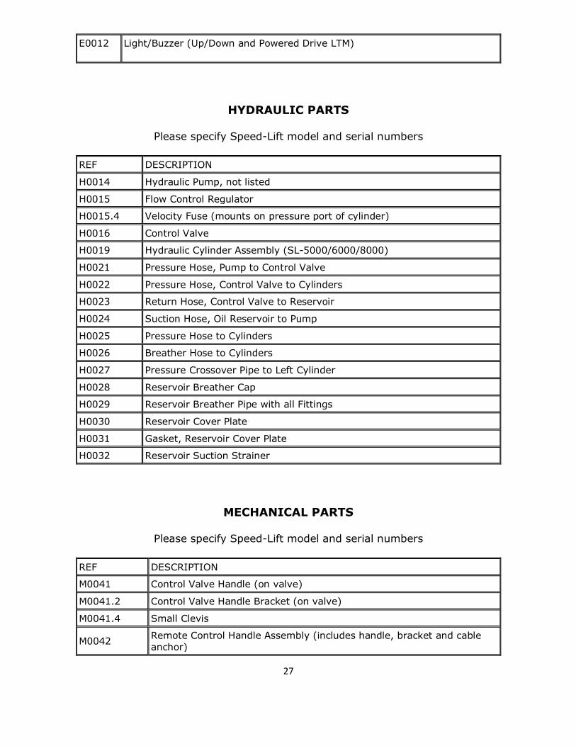
HYDRAULIC PARTS
Please specify Speed-Lift model and serial numbers
REF DESCRIPTION
H0014 Hydraulic Pump, not listed
H0015 Flow Control Regulator
H0015.4 Velocity Fuse (mounts on pressure port of cylinder)
H0016 Control Valve
H0019 Hydraulic Cylinder Assembly (SL-5000/6000/8000)
H0021 Pressure Hose, Pump to Control Valve
H0022 Pressure Hose, Control Valve to Cylinders
H0023 Return Hose, Control Valve to Reservoir
H0024 Suction Hose, Oil Reservoir to Pump
H0025 Pressure Hose to Cylinders
H0026 Breather Hose to Cylinders
H0027 Pressure Crossover Pipe to Left Cylinder
H0028 Reservoir Breather Cap
H0029 Reservoir Breather Pipe with all Fittings
H0030 Reservoir Cover Plate
H0031 Gasket, Reservoir Cover Plate
H0032 Reservoir Suction Strainer
MECHANICAL PARTS
Please specify Speed-Lift model and serial numbers
REF DESCRIPTION
M0041 Control Valve Handle (on valve)
M0041.2 Control Valve Handle Bracket (on valve)
M0041.4 Small Clevis
M0042 Remote Control Handle Assembly (includes handle, bracket and cable anchor)

28
M0042.1 Remote Handle only (mounts on platform railing)
M0042.2 Bracket for Railing Mounting of Remote Control Handle
M0042.3 Entire Remote Control Handle Kit for Bolting on Old Lifts
M0042.5 Remote Handle Cable Anchor Bracket (bracket only)
M0042.6 Large Clevis Connecting Cable to Remote Handle
M0043 132” Remote Control Handle Connecting Cable (for “A” and “B” Length Platforms except SOP)
M0043.2 180” Cable for “C” and “D” Length Platforms (except SOP)
M0043.4 204" Cable for SOP-L
M0043.6 330” Cable for SOP-R
M0043.8 348” Cable for SOP-R SL-8000
M0043.9 Rubber Boot Only For Control Cable (inc. with new cable)
M0044-EB34 Truck Bridges SL-5000/SL-6000 (34” long)
M0044-EB48 SL-5000/SL-6000 (48” long) Truck Bridge
M0044-EB68 SL-5000/SL-6000 (68” long) Truck Bridge
M00441-EB34
SL-8000/SL-1 0000 (34” long) Truck Bridge
M0044.1EB52 SL-8000/SL-1 0000 (52” long) Truck Bridge
M0044.1EB72 SL-8000/SL-1 0000 (72” long) Truck Bridge
M0044.6 Hinge Pin with Roll Pin - 1” Dia.
M0044.7 Hinge Block for 1” Dia. Pins (specify platform or bridge)
M0044.8 Hinge Pin (bridge or ramp) 1 1/2” Dia.
M0044.9 Bridge Hinge Block for 1 1/2” Dia. Pins (specify platform or bridge)
M0045 H.D. Truck Bridge Wheel (wheel only)
M0046 Adjustable HD. Bridge Wheel on Channel w/wing bolt (give Speed-Lift model)
M0046.2 Adjustable H.D. Bridge Wheel for LOB w/wing bolt
M0046.4 Adjustable Bridge Wheel Locking Wing Bolt
M0046.7 H.D. Rigid Bridge Wheel (Mounted on Reservoir)
M0047 Stabilization Jack
M0047.3 Outboard Mounted Stab. Jack Assembly (weld onto frame)
M0048 Swivel Caster Wheel (Assembly)
M0048.2 Wheel Only (6”x3” for swivel rigs)
M0048.4 Swivel Rig Only
M0049 Fixed Wheel (Axle Mounted Wheel & Bearing)
M0049.7 “V” Groove Lateral Track Mobility Wheel
M0050 Platform Off-Ramp SL-5000/6000 34” long

29
M0050.3 Platform Off-Ramp SL-8000/1 0000 34” long
M0051 Motor Cover (Specify Model)
M0052 Main Frame Assembly (Specify Model)
M0053 Main Lifting Arms/Torque Tube Assembly (Specify Model)
M0054 Upper Lifting Arm Assembly (Specify Model)
M0056 Platform Assembly (Specify Model)
M0057 Top Pin, Hydraulic Cylinder to Frame
M0058 Ball Bushing, Upper Lifting Arm
M0059 Ball Bushing, Main Lifting Arm Platform Pin
M0060 Ball Bushing, Cylinder Rod End
M0061 Ball Bushing, Top Cylinder Mounting
M0062 Torque Tube Pin (Specify Model)
M0063 Torque Tube Bushing (bearing only)
M0063.4 Torque Tube Bushing with Housing, Frame Sleeve, & Pin Assembly (specify model)
M0063.5 Torque Tube Bushing and Housing (specify model)
M0063.7 Torque Tube Frame Sleeve with Set Screws (for Torque Tube Pin)
M0064 Bolt, Upper Lifting Arm
M0065 Bolt, Main Lifting Arm
M0066 Bolt, Cylinder Rod End
M0067 Non-Skid Paint for Platform Surface (1 gal.)
M0068 Safety Chain (SC)
M0069 Aluminum Personnel Restraint Bar Assembly with Switch (PRB)
M0069.3 Aluminum Personnel Restraint Bar Assembly with Switch, Wire, and Wire Restraint
M0069.5 Aluminum Personnel Restraint Bar Cushion Cover (CC only)
M0070 Safety and Information Decal Set
M0071 Vertical Bumper Extender (give Speed-Lift model
M0072 Vertical Truck Bumpers (4” x 20”)
M0073 Horizontal Truck Bumpers for Reservoir Mounting (10”x30”)
M0074 Ground Anchors & Securing Pins (GA-set of 2)
M0074.2 Ground Anchor Slab Sockets with Pins (GA/SS set)
M0074.3 Surface Anchors (SA-including 18 expansion bolts)
M0075 Step Bumper Protectors (SBP)
M0076 Bumper Post Supports (PS-one set of 4)
M0077 Wall and Floor Anchors (WF)
M0078 Platform Stops (PLTS)

30
M0079 Ramp Winch (RW-includes all parts)
M0080 Truck Bumpers Ramp End (TBRE)

31
SPEED-LIFT DECALS
Operating Instructions, Cautions, Warnings, and Danger Decals
(Views of decal locations follow on the next two pages.)
ITEM QTY*
1 1 Caution — Familiarize Yourself...
2 1 Operating Instructions...
3 2 Safety Chain/Safety Bar Must Be Used...
4 2 No One Under 18...
5 15 Caution — Stay Away From Moving Parts.
6 3 Authorized Operators Only.
7 2 Crank Down Stabilization Jacks.
8 3 Danger — Stay Out From Under Lift Platform.
9 4 Capacity...
10 1 Danger. High Voltage..
11 1 Switch On...
12 1 Attention Electrician.
13 2 Caution — Lower Platform to Chain or Unchain Bridge...(used on special
OG Speed-Lifts Only)
14 3 Speed-Lift
15 3 Up—Down.
16 1 Serial — Nameplate...
17 1 Rotation.

32
18 2 Large — Caution Keep Away From Moving Parts
*Optional features and larger models may require extra quantities and/or special decals
IMPORTANT NOTE: It is the responsibility of the Speed-Lift Owner to properly maintain your
lift(s). Providing the decals which can be easily noticed and read by those who operate or come
near to your Speed-Lift is absolutely necessary for Speed-Lift safety. Inspect all decals every
four (4) months during Speed-Lift maintenance inspections. Replace all missing or damaged
decals immediately when noticed. Important operating instructions, cautions, warnings, and
information concerning potential dangers are contained on the Speed-Lift decals. When training
new associates to use the Speed-Lift, show each decal as a part of your training program, as
covered under Speed-Lift Operating Instructions on pages 3 and 4 of this Owner’s Manual. Thank
you for making safety your highest priority at all times!

33

34