spectrum research & reference no.: a09021301 …faenl.msi.com/ftp/ce documents/desktop...
TRANSCRIPT

Spectrum Research & Testing Lab., Inc. No. 101-10, Ling 8, Shan-Tong Li, Chung-Li City, Taoyuan, Taiwan
TEST REPORT Reference No.: A09021301 Report No.:RADA09021301 Page:1 of 71 Date: Feb. 20, 2009
Lab Code: 200099-0
FMNG-059.10 REPORT
Product Name: Personal Computer Model No.: MS-9A15 Applicant:
MICRO-STAR INT'L CO., LTD. No.69, Lide St., Jhonghe City, Taipei County 235, Taiwan
Date of Receipt: Feb. 13, 2009 Finished date of Test: Feb. 18, 2009 Applicable Standards: Radio Spectrum Matters Electromagnetic Compatibility ETSI EN 300 328 V1.7.1:2006 EN 301 489-01 V1.8.1:2008 EN 301 489-17 V1.3.2:2008
We, Spectrum Research & Testing Laboratory Inc., hereby certify that one sample of the above was tested in our laboratory with positive results according to the above-mentioned standards. The records in the report are an accurate account of the results. Details of the results are given in the subsequent pages of this report. Tested By:
, Date:
Approved By:
(Shunm Wang)
, Date:
(Johnson Ho, Director)

Spectrum Research & Testing Lab., Inc. No. 101-10, Ling 8, Shan-Tong Li, Chung-Li City, Taoyuan, Taiwan
TEST REPORT Reference No.: A09121301 Report No.:RADA09121301 Page:2 of 71 Date: Feb. 20, 2009
FMNG-059.10 REPORT
TABLE OF CONTENTS 1. DOCUMENT POLICY AND TEST STATEMENT................................................... 5 1.1 DOCUMENT POLICY......................................................................................... 5 1.2 TEST STATEMENT ............................................................................................ 5 1.3 EUT MODIFICATION.......................................................................................... 5 2. DESCRIPTION OF EUT AND TEST MODE ......................................................... 6 2.1 GENERAL DESCRIPTION OF EUT ................................................................... 6 2.2 DESCRIPTION OF EUT INTERNAL DEVICE .................................................... 6 2.3 DESCRIPTION OF TEST MODE ....................................................................... 7 2.4 DESCRIPTION OF SUPPORT UNIT.................................................................. 7 2.5 EUT OPERATING CONDITION.......................................................................... 8 3. DESCRIPTION OF APPLIED STANDARDS......................................................... 8 4 TECHNICAL CHARACTERISTICS TEST FOR TRANSMITTER PART................. 9 4.1 EFFECTIVE ISOTROPICALLY RADIATED POWER.......................................... 9 4.1.1 EFFECTIVE ISOTROPICALLY RADIATED POWER LIMIT ............................ 9 4.1.2 TEST EQUIPMENT .........................................................................................9 4.1.3 TEST SETUP.................................................................................................10 4.1.4 TEST PROCEDURE......................................................................................10 4.1.5 TEST RESULT............................................................................................... 11 4.2 PEAK POWER DENSITY ................................................................................. 12 4.2.1 PEAK POWER DENSITY LIMIT.......................................................................12 4.2.2 TEST EQUIPMENT .......................................................................................12 4.2.3 TEST SETUP.................................................................................................13 4.2.4 TEST PROCEDURE......................................................................................13 4.2.5 TEST RESULT............................................................................................... 14 4.3 FREQUENCY RANGE ..................................................................................... 15 4.3.1 FREQUENCY RANGE LIMIT.........................................................................15 4.3.2 TEST EQUIPMENT .......................................................................................15 4.3.3 TEST PROCEDURES....................................................................................15 4.3.4 TEST SETUP.................................................................................................16 4.3.5 TEST RESULT...............................................................................................17 4.4 SPURIOUS EMISSION FROM TRANSMITTER............................................... 19 4.4.1 LIMIT..............................................................................................................19 4.4.2 TEST EQUIPMENT .......................................................................................20 4.4.3 TEST SETUP.................................................................................................21 4.4.4 TEST PROCEDURE......................................................................................22 4.4.5 TEST RESULT...............................................................................................22 5. CONDUCTED EMISSION TEST ........................................................................32 5.1 LIMIT.................................................................................................................32 5.2 TEST EQUIPMENT .......................................................................................... 32 5.3 TEST PROCEDURE......................................................................................... 33 5.4 TEST SETUP.................................................................................................... 33 5.5 TEST RESULT.................................................................................................. 34 6. CURRENT HARMONICS TEST..........................................................................38

Spectrum Research & Testing Lab., Inc. No. 101-10, Ling 8, Shan-Tong Li, Chung-Li City, Taoyuan, Taiwan
TEST REPORT Reference No.: A09121301 Report No.:RADA09121301 Page:3 of 71 Date: Feb. 20, 2009
FMNG-059.10 REPORT
6.1 LIMIT FOR CLASS A EQUIPMENT .................................................................. 38 6.2 TEST EQUIPMENT ..........................................................................................39 6.3 TEST SETUP....................................................................................................39 6.4 TEST PROCEDURE.........................................................................................39 6.5 DESCRIPTION OF SUPPORT UNIT ................................................................39 6.6 EUT OPERATING CONDITION........................................................................39 6.7 SUMMARY OF CURRENT HARMONICS TEST RESULT................................40 7. VOLTAGE FLUCTUATIONS..............................................................................41 7.1 LIMIT ................................................................................................................ 41 7.2 TEST EQUIPMENT .......................................................................................... 41 7.3 TEST PROCEDURE......................................................................................... 41 7.4 TEST SETUP.................................................................................................... 41 7.5 DESCRIPTION OF SUPPORT UNIT................................................................ 41 7.6 EUT OPERATING CONDITION........................................................................ 41 7.7 SUMMARY OF VOLTAGE FLUCTUATIONS TEST RESULT............................42 8. ELECTROSTATIC DISCHARGE.........................................................................43 8.1 TEST EQUIPMENT .......................................................................................... 43 8.2 TEST PROCEDURE.........................................................................................43 8.3 TEST SET-UP...................................................................................................44 8.4 TEST CONDITION AND PERFORMANCE ...................................................... 45 8.5 GENERAL PERFORMANCE CRITERIA DESCRIPTION .................................45 8.6 TEST RESULT.................................................................................................. 48 9. RADIATED IMMUNITY TEST .............................................................................49 9.1 TEST EQUIPMENT ..........................................................................................49 9.2 TEST PROCEDURE......................................................................................... 50 9.3 TEST SETUP....................................................................................................50 9.4 TEST CONDITION............................................................................................51 9.5 GENERAL PERFORMANCE CRITERIA DESCRIPTION................................. 52 9.6 TEST RESULT.................................................................................................. 54 10. ELECTRICAL FAST TRANSIENT / BURST IMMUNITY TEST .........................55 10.1 TEST EQUIPMENT ........................................................................................ 55 10.2 TEST PROCEDURE.......................................................................................55 10.3 TEST SET-UP.................................................................................................55 10.4 TEST CONDITION/PERFORMANCE CRITERIA ........................................... 56 10.5 SUMMARY OF TEST RESULT.......................................................................56 11. INDUCED RF FIELDS (CONDUCTED SUSCEPTIBILITY) TEST.....................57 11.1 TEST EQUIPMENT......................................................................................... 57 11.2 TEST PROCEDURE....................................................................................... 58 11.3 TEST SET-UP................................................................................................. 58 11.4 TEST CONDITION / PERFORMANCE CRITERIA ......................................... 59 11.5 SUMMARY OF TEST RESULT .......................................................................59 12. SURGE TEST ...................................................................................................60 12.1 TEST EQUIPMENT ........................................................................................ 60 12.2 TEST PROCEDURE....................................................................................... 60 12.3 TEST SET-UP................................................................................................. 60

Spectrum Research & Testing Lab., Inc. No. 101-10, Ling 8, Shan-Tong Li, Chung-Li City, Taoyuan, Taiwan
TEST REPORT Reference No.: A09121301 Report No.:RADA09121301 Page:4 of 71 Date: Feb. 20, 2009
FMNG-059.10 REPORT
12.4 DESCRIPTION OF SUPPORT UNIT.............................................................. 60 12.5 EUT OPERATING CONDITION...................................................................... 60 12.6 TEST CONDITION / PERFORMANCE CRITERIA ......................................... 61 12.7 SUMMARY OF TEST RESULT....................................................................... 61 13. VOLTAGE DIPS, INTERRUPTS TEST .............................................................62 13.1 TEST EQUIPMENT ........................................................................................ 62 13.2 TEST PROCEDURE....................................................................................... 62 13.3 TEST SET-UP................................................................................................. 62 13.4 DESCRIPTION OF SUPPORT UNIT.............................................................. 62 13.5 EUT OPERATING CONDITION...................................................................... 62 13.6 TEST CONDITION / PERFORMANCE CRITERIA ......................................... 63 13.7 SUMMARY OF TEST RESULT....................................................................... 63 14. PHOTOS OF TESTING ....................................................................................64 15. TERMS OF ABRIVATION .................................................................................71

Spectrum Research & Testing Lab., Inc. No. 101-10, Ling 8, Shan-Tong Li, Chung-Li City, Taoyuan, Taiwan
TEST REPORT Reference No.: A09121301 Report No.:RADA09121301 Page:5 of 71 Date: Feb. 20, 2009
FMNG-059.10 REPORT
1. DOCUMENT POLICY AND TEST STATEMENT
1.1 DOCUMENT POLICY
- The report shall not be reproduced except in full, without the written approval of SRT Lab, Inc.
- The report must not be used by the client to claim product certification, approval, or endorsement by NVLAP, NIST, or any agency of the Federal Government.
1.2 TEST STATEMENT - The test results in the report apply only to the unit tested by SRT Lab.
- There was no deviation from the requirements of test standards during the test.
- AC power source, 230 VAC/50 Hz, was used during the test.
1.3 EUT MODIFICATION - No modification in SRT Lab.

Spectrum Research & Testing Lab., Inc. No. 101-10, Ling 8, Shan-Tong Li, Chung-Li City, Taoyuan, Taiwan
TEST REPORT Reference No.: A09121301 Report No.:RADA09121301 Page:6 of 71 Date: Feb. 20, 2009
FMNG-059.10 REPORT
2. DESCRIPTION OF EUT AND TEST MODE 2.1 GENERAL DESCRIPTION OF EUT
PRODUCT Personal Computer MODEL NO. MS-9A15 POWER SUPPLY DC 3.3V CABLE N/A FREQUENCY BAND 2.4GHz ~ 2.5GHz CARRIER FREQUENCY 2.412GHz ~ 2.484GHz NUMBER OF CHANNEL 14 CHANNEL SPACING 5MHz RATED RF OUTPUT POWER 14 dBm(ERP)
MODULATION TYPE OFDM MODE OF OPERATION Half Duplex BIT RATE OF TRANSMISSION 54Mbps
ANTENNA TYPE Dipole OPERATING TEMPERATURE RANGE 0 ~ 70°C
NOTE : 1. For more detailed information, please refer to the EUT’s specification or user’s manual provided by
manufacturer.
2.2 DESCRIPTION OF EUT INTERNAL DEVICE
DEVICE BRAND / MAKER MODEL REMARK CPU INTEL ATOM N270 1.6GHz
RAM Samsung M470T2864QZ3-CE6 1GB
Motherboard MSI MS-N0111 N/A
HDD TOSHIBA MK1652GSX 160GB

Spectrum Research & Testing Lab., Inc. No. 101-10, Ling 8, Shan-Tong Li, Chung-Li City, Taoyuan, Taiwan
TEST REPORT Reference No.: A09121301 Report No.:RADA09121301 Page:7 of 71 Date: Feb. 20, 2009
FMNG-059.10 REPORT
2.3 DESCRIPTION OF TEST MODE 11 channels are provided by EUT of wireless. The 3 channels of lower, medium and higher were chosen for test. There are test modes for each test configuration as below:
Mode Modulation Type Channel Frequency (MHz)1 CH1 2412 2 CH6 2437 3
IEEE 802.11g
OFDM
CH11 2462 4 CH1 2412 5 CH6 2437 6
IEEE 802.11b
CCK
CH11 2462 7 Standby N/A N/A N/A 8 Link N/A N/A N/A
NOTE : 1. Below 1 GHz, the channel 1, 6 and 11 were pre-tested in chamber. The channel 11, worst case one,
was chosen for conducted and radiated emission test. 2. Above 1 GHz, the channel 1, 6 and 11 were tested individually.
2.4 DESCRIPTION OF SUPPORT UNIT
The EUT was configured by the requirement of EN 55022:2006. All interface ports were connected to the appropriate support units via specific cables. The support units and cables are listed below. NO DEVICE BRAND MODEL CABLE
1 USB Keyboard Acer 6511-UV 1.5 m shielded data cable.
2 USB Mouse Logitech M-BE58 1.5m shielded data cable with one core
3 USB HDD TERASYS F12-U 1.5m shielded data cable.
4 CRT Monitor SAMSUNG PG17IS 1.8m unshielded power cord 1.5m shielded data cable. with one core.
5 Earphone Ergotech ET-E241 1.8m unshielded data cable.
6 XD card Toshiba DPC-M2GB 2GB
NOTE : For the actual test configuration, please refer to the photos of testing.

Spectrum Research & Testing Lab., Inc. No. 101-10, Ling 8, Shan-Tong Li, Chung-Li City, Taoyuan, Taiwan
TEST REPORT Reference No.: A09121301 Report No.:RADA09121301 Page:8 of 71 Date: Feb. 20, 2009
FMNG-059.10 REPORT
2.5 EUT OPERATING CONDITION 1.Setup the EUT and all peripheral devices. 2.Turn on the power of all equipment and EUT. 3.We will use the following programs under Windows Home server system to test EUT. 3.1 "EMC Test" program. EUT will read data from storage devices and then writes the data into storage devices. PC sent "H" pattern signal and detect following peripherals directly or via EUT: - Keyboard - Mouse - Monitor - HDD 3.2"Ping" program Use the ping command to link LAN port and local simulation EUT through Ethernet hub. 3.3”Media Player” program Run Windows Media Player program to test Video and Audio devices. 3.4"MyHwin" program
PC sends "H" pattern signal to monitor and monitor will show "full screen H pattern" 3. DESCRIPTION OF APPLIED STANDARDS The EUT is a kind of wireless product. According to the specifications provided by the applicant, it must comply with the requirements of the following standards:
All tests have been performed and recorded as the above standards.
ETSI EN 300 328 V1.7.1:2006 EN 301 489-01 V1.8.1:2008 - EN 55022:2006, Class B EN 301 489-17 V1.3.2:2008 - IEC 61000-3-2:2006 - EN 55024:1998+A1:2001+A2:2003
- IEC 61000-3-3:1995+A1:2001+A2:2005 - IEC 61000-4-2:2001 - IEC 61000-4-3:2006 - IEC 61000-4-4:2004 - IEC 61000-4-5:2005 - IEC 61000-4-6:2006 - IEC 61000-4-11:2004

Spectrum Research & Testing Lab., Inc. No. 101-10, Ling 8, Shan-Tong Li, Chung-Li City, Taoyuan, Taiwan
TEST REPORT Reference No.: A09121301 Report No.:RADA09121301 Page:9 of 71 Date: Feb. 20, 2009
FMNG-059.10 REPORT
4 TECHNICAL CHARACTERISTICS TEST FOR TRANSMITTER PART 4.1 EFFECTIVE ISOTROPICALLY RADIATED POWER 4.1.1 EFFECTIVE ISOTROPICALLY RADIATED POWER LIMIT
DSSS FHSS PK. 200mW(23dBm) 200mW(23dBm) AV. 100mW(20dBm) 100mW(20dBm)
Note: The “(dBm)’” was calculated from power(mW).
Formula: (0) dBm=10 log 1 mW 4.1.2 TEST EQUIPMENT The following test equipment was used for the test:
EQUIPMENT/ FACILITIES
SPECIFICATIONS MANUFACTURERMODEL#/ SERIAL#
DUE DATE OF CAL. & CAL. CENTER
TEMPERATURE & HUMIDITY CHAMBER
-70 to 180°C 0 to 100%
KSON THS-D4H+-150/ 1801
NOV. 2009 ETC
HORN ANTENNA 1GHz to 18GHz EMCO 3115/ 9012-3619
DEC. 2009 ETC
HORN ANTENNA 1GHz to 18GHz EMCO 3115/ 9602-4681
NOV. 2009 ETC
POWER METER N/A BOOTON 4232A/ 29001
MAY 2009 ETC
POWER SENSOR DC-18GHz 0.3 µW-100mW 50 Ω
BOOTON 51011EMC/ 31181
NOV. 2009 BOOTON
DETECTOR 2GHz-18GHz OMNIYIG DT9A4P/ 7917-0236
NOV. 2009 SRT
OSCILLOSCOPE 100MHz, 400V HP 54645A/ US39151317
APR. 2009 HP, ITRI
SIGNAL GENERATOR
1GHz-20GHz ROHDE& SCHWARZ
SMR20/ 100046
JUN. 2009 ETC
DC POWER SUPPLY 0 to 20Vdc 0 to 50A
Lurich RPS-1512MB/ 910054
Calibrated by multimeter
NOTE : The calibration interval of the above test equipment is one year and the calibrations are traceable to NML/ROC and NIST/USA.
Spectrum Research & Testing Lab., Inc. No. 101-10, Ling 8, Shan-Tong Li, Chung-Li City, Taoyuan, Taiwan
TEST REPORT Reference No.: A09121301 Report No.:RADA09121301 Page:10 of 71 Date: Feb. 20, 2009
FMNG-059.10 REPORT
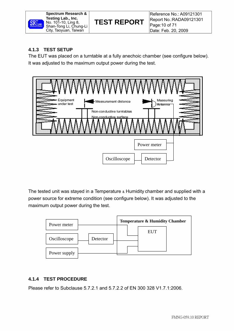
4.1.3 TEST SETUP The EUT was placed on a turntable at a fully anechoic chamber (see configure below). It was adjusted to the maximum output power during the test.
The tested unit was stayed in a Temperature & Humidity chamber and supplied with a power source for extreme condition (see configure below). It was adjusted to the maximum output power during the test.
4.1.4 TEST PROCEDURE
Please refer to Subclause 5.7.2.1 and 5.7.2.2 of EN 300 328 V1.7.1:2006.
Temperature & Humidity Chamber Power meter
EUT
Power supply
DetectorOscilloscope
Power meter
DetectorOscilloscope

Spectrum Research & Testing Lab., Inc. No. 101-10, Ling 8, Shan-Tong Li, Chung-Li City, Taoyuan, Taiwan
TEST REPORT Reference No.: A09121301 Report No.:RADA09121301 Page:11 of 71 Date: Feb. 20, 2009
FMNG-059.10 REPORT
4.1.5 TEST RESULT Temperature: 22°C Humidity: 66%RH Tested By: Shunm Wang Tested Mode: IEEE 802.11b Tested Date: Feb. 16, 2009 Modulation Type: CCK
CHANNEL
FREQUENCY(MHz)
CH1
2412MHZ
CH6
2437MHz
CH8
2447MHz CH11
2462MHz
Temperature
(°C)
PK
(dBm)
AV
(dBm)
PK
(dBm)
AV
(dBm)
PK
(dBm)
AV
(dBm)
PK
(dBm)
AV
(dBm)
Norm 20 10.25 8.81 9.49 7.66 10.15 8.38 11.66 9.67
Low -20 10.36 8.76 9.42 7.60 10.19 8.41 11.57 9.62
High 55 10.33 8.82 9.41 7.67 10.16 8.32 11.63 9.69
Note: Measurement Uncertainty: ±0.5dB
Temperature: 22°C Humidity: 66%RH Tested By: Shunm Wang Tested Mode: IEEE 802.11g Tested Date: Feb. 16, 2009 Modulation Type: OFDM
CHANNEL
FREQUENCY(MHz)
CH1
2412MHZ
CH6
2437MHz
CH8
2447MHz CH11
2462MHz
Temperature
(°C)
PK
(dBm)
AV
(dBm)
PK
(dBm)
AV
(dBm)
PK
(dBm)
AV
(dBm)
PK
(dBm)
AV
(dBm)
Norm 20 8.30 6.92 7.89 5.81 8.02 6.54 9.13 7.92
Low -20 8.24 6.90 7.98 5.90 7.91 6.48 9.02 7.87
High 55 8.39 6.94 7.95 5.88 7.95 6.50 9.18 7.93
Note: Measurement Uncertainty: ±0.5dB

Spectrum Research & Testing Lab., Inc. No. 101-10, Ling 8, Shan-Tong Li, Chung-Li City, Taoyuan, Taiwan
TEST REPORT Reference No.: A09121301 Report No.:RADA09121301 Page:12 of 71 Date: Feb. 20, 2009
FMNG-059.10 REPORT
4.2 PEAK POWER DENSITY
4.2.1 PEAK POWER DENSITY LIMIT
DSSS FHSS LIMIT 10mW/1MHz(10dBm/1MHz) 100mW/100kHz(20dBm/100kHz)
NOTE : The “(dBm)’” was calculated from power(mW). Formula: (0) dBm=10 log 1 mW
4.2.2 TEST EQUIPMENT The following test equipment was used for the test:
EQUIPMENT/ FACILITIES
SPECIFICATIONS MANUFACTURERMODEL#/ SERIAL#
DUE DATE OF CAL. & CAL. CENTER
SPECTRUM 9kHz-40GHz ROHDE & SCHWARZ
FSP40/ 100093
SEP. 2009 ETC
POWER METER N/A BOONTON 4232A/ 29001
MAY 2009 ETC
POWER SENSOR DC-18GHz
0.3μW-100mW 50Ω
BOONTON 51011-EMC/
31184 JUN. 2009
ETC
NOTE : The calibration interval of the above test equipment is one year and the calibrations are traceable to NML/ROC and NIST/USA.
Spectrum Research & Testing Lab., Inc. No. 101-10, Ling 8, Shan-Tong Li, Chung-Li City, Taoyuan, Taiwan
TEST REPORT Reference No.: A09121301 Report No.:RADA09121301 Page:13 of 71 Date: Feb. 20, 2009
FMNG-059.10 REPORT
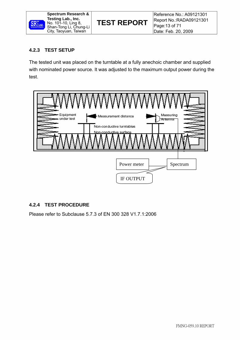
4.2.3 TEST SETUP The tested unit was placed on the turntable at a fully anechoic chamber and supplied with nominated power source. It was adjusted to the maximum output power during the test.
4.2.4 TEST PROCEDURE
Please refer to Subclause 5.7.3 of EN 300 328 V1.7.1:2006
Spectrum Power meter
IF OUTPUT

Spectrum Research & Testing Lab., Inc. No. 101-10, Ling 8, Shan-Tong Li, Chung-Li City, Taoyuan, Taiwan
TEST REPORT Reference No.: A09121301 Report No.:RADA09121301 Page:14 of 71 Date: Feb. 20, 2009
FMNG-059.10 REPORT
4.2.5 TEST RESULT Temperature: 22°C Humidity: 68%RH Spectrum Detector: PK. Tested Mode: IEEE 802.11b Tested By: Shunm Wang Modulation Type: CCK Tested Date: Feb. 16, 2009
CHANNEL FREQUENCY(MHZ)
POWER (dBm)/kHz Antenna
polarization Limit
(dBm/kHz) CH1:2412MHz -9.83/1MHz H 10/1MHz
CH6: 2437MHz -9.02/1MHz H 10/1MHz
CH8: 2447MHz -9.13/1MHz H 10/1MHz
CH11: 2462MHz -9.05/1MHz H 10/1MHz
Measurement uncertainty
+/-3dB
Temperature: 23°C Humidity: 62%RH Spectrum Detector: PK. Tested Mode: IEEE 802.11g Tested By: Shunm Wang Modulation Type: OFDM Tested Date: Feb. 16, 2009
CHANNEL FREQUENCY(MHZ)
POWER (dBm)/kHz Antenna
polarization Limit
(dBm/kHz) CH1:2412MHz -13.72/1MHz H 10/1MHz
CH6: 2437MHz -12.62/1MHz H 10/1MHz
CH8: 2447MHz -12.68/1MHz H 10/1MHz
CH11: 2462MHz -12.79/1MHz H 10/1MHz
Measurement uncertainty
+/-3dB

Spectrum Research & Testing Lab., Inc. No. 101-10, Ling 8, Shan-Tong Li, Chung-Li City, Taoyuan, Taiwan
TEST REPORT Reference No.: A09121301 Report No.:RADA09121301 Page:15 of 71 Date: Feb. 20, 2009
FMNG-059.10 REPORT
4.3 FREQUENCY RANGE
4.3.1 FREQUENCY RANGE LIMIT
COUNTRY LIMIT (MHz)
European Union 2400~2483.5
FRANCE 2446.5~2483.5
4.3.2 TEST EQUIPMENT The following test equipment was used for the test:
EQUIPMENT/ FACILITIES
SPECIFICATIONS MANUFACTURERMODEL#/ SERIAL#
DUE DATE OF CAL. & CAL. CENTER
SPECTRUM 9kHz-40GHz ROHDE & SCHWARZ
FSP40/ 100093
SEP. 2009 ETC
TEMPERATURE & HUMIDITY CHAMBER
-70 to 180°C 0 to 100%
KSON THS-D4H+-150/
1801 NOV. 2009
ETC
MULTIMETER N/A HP E2377A/
2927J05810 AUG. 2009
ETC
DC POWER SUPPLY 0 to 20Vdc 0 to 50A
Lurich RPS-1512MB/
910054 Calibrated by
multimeter
NOTE : The calibration interval of the above test equipment is one year and the calibrations are traceable to NML/ROC and NIST/USA.
4.3.3 TEST PROCEDURES Please refer to Subclause 5.7.4.2 of EN 300 328 V1.7.1:2006.

Spectrum Research & Testing Lab., Inc. No. 101-10, Ling 8, Shan-Tong Li, Chung-Li City, Taoyuan, Taiwan
TEST REPORT Reference No.: A09121301 Report No.:RADA09121301 Page:16 of 71 Date: Feb. 20, 2009
FMNG-059.10 REPORT
4.3.4 TEST SETUP The EUT was s placed on a turntable at a fully anechoic chamber (see configure below). It was adjusted to the maximum output power during the test.
Then tested unit was stayed in a Temperature & Humidity chamber and supplied with power source for extreme condition(see configure below). It was adjusted to the maximum output power during the test.
Temperature & Humidity Chamber
EUT
Receiver or Spectrum
Power supply
Spectrum
Spectrum Research & Testing Lab., Inc. No. 101-10, Ling 8, Shan-Tong Li, Chung-Li City, Taoyuan, Taiwan
TEST REPORT Reference No.: A09121301 Report No.:RADA09121301 Page:17 of 71 Date: Feb. 20, 2009
FMNG-059.10 REPORT
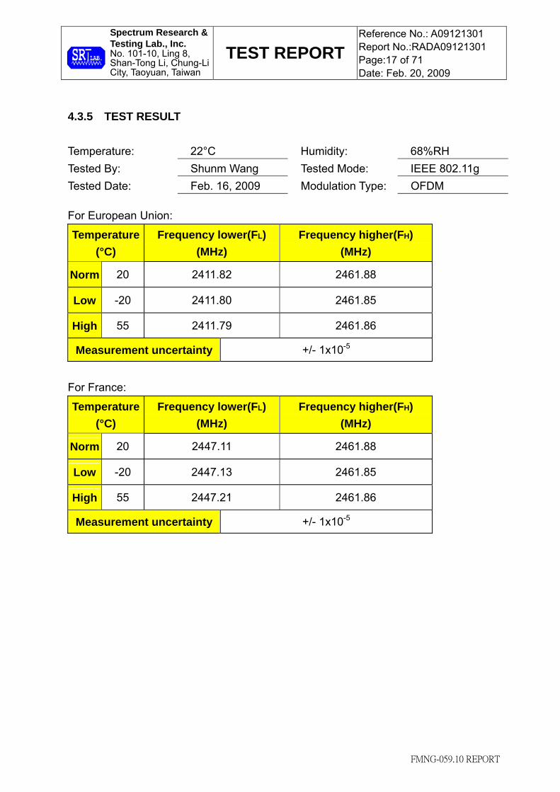
4.3.5 TEST RESULT Temperature: 22°C Humidity: 68%RH Tested By: Shunm Wang Tested Mode: IEEE 802.11g Tested Date: Feb. 16, 2009 Modulation Type: OFDM For European Union:
Temperature (°C)
Frequency lower(FL) (MHz)
Frequency higher(FH) (MHz)
Norm 20 2411.82 2461.88
Low -20 2411.80 2461.85
High 55 2411.79 2461.86
Measurement uncertainty +/- 1x10⁻⁵
For France:
Temperature (°C)
Frequency lower(FL) (MHz)
Frequency higher(FH) (MHz)
Norm 20 2447.11 2461.88
Low -20 2447.13 2461.85
High 55 2447.21 2461.86
Measurement uncertainty +/- 1x10⁻⁵

Spectrum Research & Testing Lab., Inc. No. 101-10, Ling 8, Shan-Tong Li, Chung-Li City, Taoyuan, Taiwan
TEST REPORT Reference No.: A09121301 Report No.:RADA09121301 Page:18 of 71 Date: Feb. 20, 2009
FMNG-059.10 REPORT
Temperature: 22°C Humidity: 64%RH Tested By: Shunm Wang Tested Mode: IEEE 802.11b Tested Date: Feb. 16, 2009 Modulation Type: CCK For European Union:
Temperature (°C)
Frequency lower(FL) (MHz)
Frequency higher(FH) (MHz)
Norm 20 2411.79 2461.90
Low -20 2411.76 2461.87
High 55 2411.75 2461.84
Measurement uncertainty +/- 1x10⁻⁵
For France:
Temperature (°C)
Frequency lower(FL) (MHz)
Frequency higher(FH) (MHz)
Norm 20 2447.15 2461.90
Low -20 2447.17 2461.87
High 55 2447.16 2461.84
Measurement uncertainty +/- 1x10⁻⁵
Spectrum Research & Testing Lab., Inc. No. 101-10, Ling 8, Shan-Tong Li, Chung-Li City, Taoyuan, Taiwan
TEST REPORT Reference No.: A09121301 Report No.:RADA09121301 Page:19 of 71 Date: Feb. 20, 2009
FMNG-059.10 REPORT
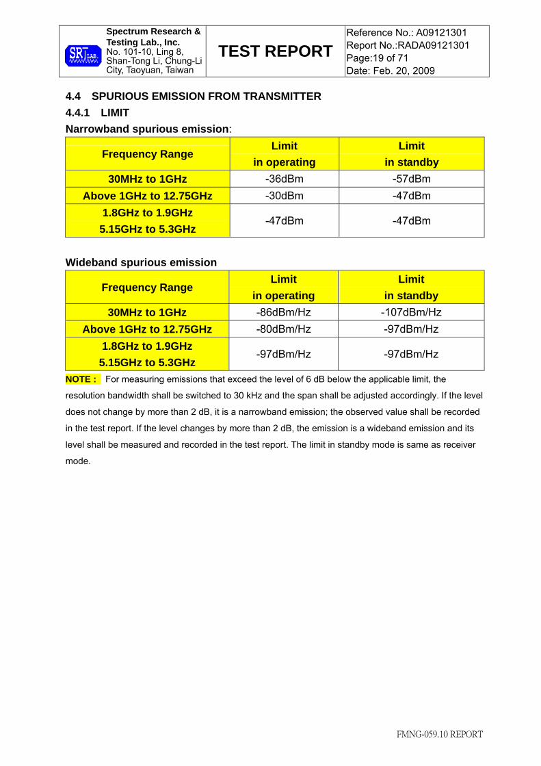
4.4 SPURIOUS EMISSION FROM TRANSMITTER 4.4.1 LIMIT Narrowband spurious emission:
Frequency Range Limit
in operating Limit
in standby 30MHz to 1GHz -36dBm -57dBm
Above 1GHz to 12.75GHz -30dBm -47dBm 1.8GHz to 1.9GHz
5.15GHz to 5.3GHz -47dBm -47dBm
Wideband spurious emission
Frequency Range Limit
in operating Limit
in standby 30MHz to 1GHz -86dBm/Hz -107dBm/Hz
Above 1GHz to 12.75GHz -80dBm/Hz -97dBm/Hz 1.8GHz to 1.9GHz 5.15GHz to 5.3GHz
-97dBm/Hz -97dBm/Hz
NOTE : For measuring emissions that exceed the level of 6 dB below the applicable limit, the
resolution bandwidth shall be switched to 30 kHz and the span shall be adjusted accordingly. If the level
does not change by more than 2 dB, it is a narrowband emission; the observed value shall be recorded
in the test report. If the level changes by more than 2 dB, the emission is a wideband emission and its
level shall be measured and recorded in the test report. The limit in standby mode is same as receiver
mode.
Spectrum Research & Testing Lab., Inc. No. 101-10, Ling 8, Shan-Tong Li, Chung-Li City, Taoyuan, Taiwan
TEST REPORT Reference No.: A09121301 Report No.:RADA09121301 Page:20 of 71 Date: Feb. 20, 2009
FMNG-059.10 REPORT
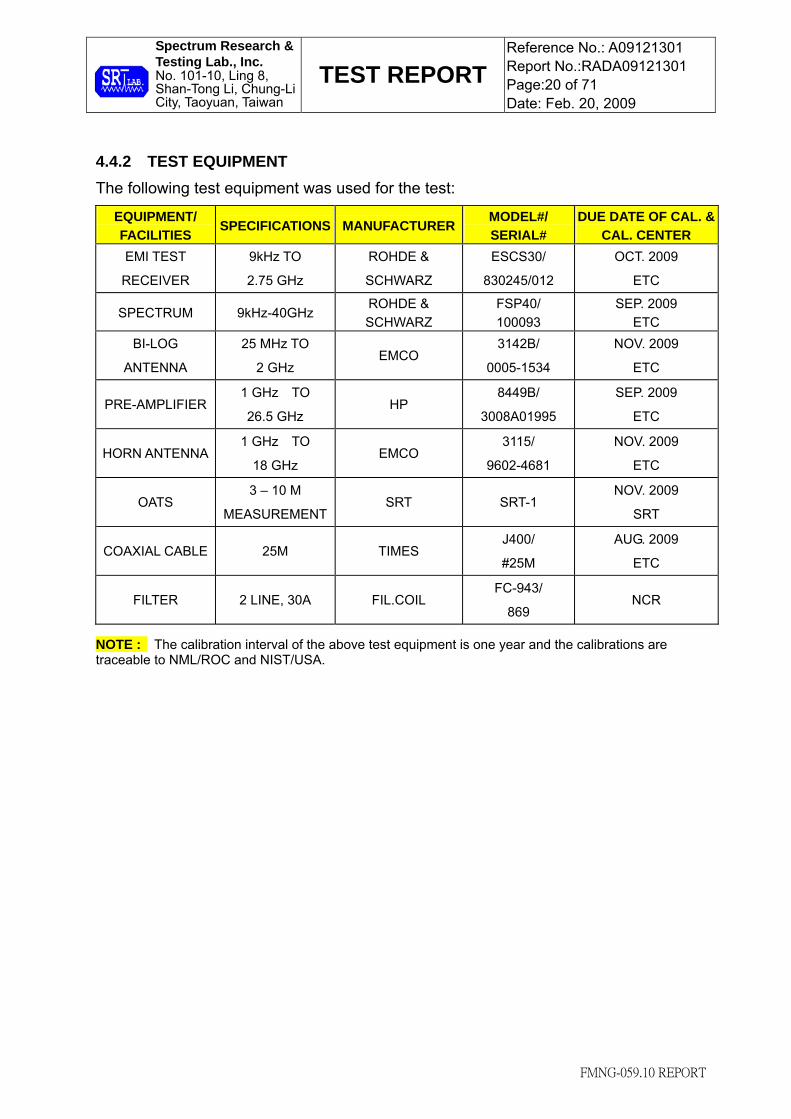
4.4.2 TEST EQUIPMENT The following test equipment was used for the test:
EQUIPMENT/ FACILITIES
SPECIFICATIONS MANUFACTURERMODEL#/ SERIAL#
DUE DATE OF CAL. & CAL. CENTER
EMI TEST
RECEIVER
9kHz TO
2.75 GHz
ROHDE &
SCHWARZ
ESCS30/
830245/012
OCT. 2009
ETC
SPECTRUM 9kHz-40GHz ROHDE & SCHWARZ
FSP40/ 100093
SEP. 2009 ETC
BI-LOG
ANTENNA
25 MHz TO
2 GHz EMCO
3142B/
0005-1534
NOV. 2009
ETC
PRE-AMPLIFIER 1 GHz TO
26.5 GHz HP
8449B/
3008A01995
SEP. 2009
ETC
HORN ANTENNA 1 GHz TO
18 GHz EMCO
3115/
9602-4681
NOV. 2009
ETC
OATS 3 – 10 M
MEASUREMENTSRT SRT-1
NOV. 2009
SRT
COAXIAL CABLE 25M TIMES J400/
#25M
AUG. 2009
ETC
FILTER 2 LINE, 30A FIL.COIL FC-943/
869 NCR
NOTE : The calibration interval of the above test equipment is one year and the calibrations are traceable to NML/ROC and NIST/USA.

Spectrum Research & Testing Lab., Inc. No. 101-10, Ling 8, Shan-Tong Li, Chung-Li City, Taoyuan, Taiwan
TEST REPORT Reference No.: A09121301 Report No.:RADA09121301 Page:21 of 71 Date: Feb. 20, 2009
FMNG-059.10 REPORT
4.4.3 TEST SETUP The tested unit was placed on a turntable at an open area test site and supplied with nominated power source, when the emission frequency was tested lower than 1GHz (see configure below). It was adjusted to the maximum output power during the test.
The EUT was placed on a turntable at a fully anechoic chamber when the emission frequency was tested above 1GHz (see configure below). It was adjusted to the maximum output power during the test.
Pre-amplifier Spectrum

Spectrum Research & Testing Lab., Inc. No. 101-10, Ling 8, Shan-Tong Li, Chung-Li City, Taoyuan, Taiwan
TEST REPORT Reference No.: A09121301 Report No.:RADA09121301 Page:22 of 71 Date: Feb. 20, 2009
FMNG-059.10 REPORT
4.4.4 TEST PROCEDURE
Please refer to Subclause 5.7.5 of EN 300 328 V1.7.1:2006 4.4.5 TEST RESULT Temperature: 23 °C Humidity: 68 %RH Tested By: Shunm Wang Tested Mode: Standby Tested Date: Feb. 19, 2009 Modulation Type: N/A Tested Result: Pass Tested Channel: N/A Antenna Polarization: Horizontal
Frequency (MHz)
Cable Loss (dB)
Antenna Factor (dB/m)
Reading Data
(dBm)
EmissionLevel (dBm)
Limit (dBm)
Margin (dB)
AZ (o)
EL (m)
35.8200 1.05 16.90 -88.8 -70.9 -57.0 -13.9 152 3.31 60.0700 1.40 8.70 -86.9 -76.8 -57.0 -19.8 306 3.28 88.2100 1.68 8.32 -78.4 -68.4 -57.0 -11.4 174 3.11 128.9410 2.08 8.22 -82.1 -71.8 -57.0 -14.8 225 2.82 157.0720 2.36 9.05 -83.8 -72.4 -57.0 -15.4 83 2.72 175.5100 2.50 9.70 -82.0 -69.8 -57.0 -12.8 102 2.37
Antenna Polarization: Vertical
Frequency (MHz)
Cable Loss (dB)
Antenna Factor (dB/m)
Reading Data
(dBm)
EmissionLevel (dBm)
Limit (dBm)
Margin (dB)
AZ (o)
EL (m)
35.8200 1.05 16.90 -88.6 -70.7 -57.0 -13.7 143 2.00 60.0710 1.40 8.70 -87.8 -77.7 -57.0 -20.7 315 2.15 128.9406 2.08 8.22 -85.7 -75.4 -57.0 -18.4 209 1.93 160.9520 2.38 9.20 -85.1 -73.5 -57.0 -16.5 16 1.85 177.4390 2.52 9.74 -82.4 -70.1 -57.0 -13.1 358 1.97 226.9110 2.91 11.60 -83.6 -69.1 -57.0 -12.1 175 1.91
NOTE : 1. Measurement uncertainty is +/-3.7dB. 2. "*": Measurement does not apply for this frequency. 3. Emission Level = Reading Value + Ant. Factor + Cable Loss. 4. The field strength of other emission frequencies were very low against the limit.

Spectrum Research & Testing Lab., Inc. No. 101-10, Ling 8, Shan-Tong Li, Chung-Li City, Taoyuan, Taiwan
TEST REPORT Reference No.: A09121301 Report No.:RADA09121301 Page:23 of 71 Date: Feb. 20, 2009
FMNG-059.10 REPORT
Temperature: 23 °C Humidity: 68 %RH Tested By: Shunm Wang Tested Mode: Link Frequency Range: 30M – 1GHz Receiver Detector: Q.P. or AV. Modulation Type: N/A Tested Result: Pass Tested Date: Feb. 19, 2009 Antenna Polarization: Horizontal
Frequency (MHz)
Cable Loss (dB)
Antenna Factor (dB/m)
Reading Data
(dBm)
EmissionLevel (dBm)
Limit (dBm)
Margin (dB)
AZ (o)
EL (m)
35.8200 1.05 16.90 -88.8 -70.9 -36.0 -34.9 153 3.34 60.0710 1.40 8.70 -82.0 -71.9 -36.0 -35.9 271 3.17 130.8810 2.10 8.20 -80.9 -70.6 -36.0 -34.6 335 2.9 184.2300 2.57 9.96 -79.9 -67.4 -36.0 -31.4 156 2.76 256.0110 3.15 12.86 -83.1 -67.1 -36.0 -31.1 149 2.15 275.4130 3.30 13.53 -82.8 -66.0 -36.0 -30.0 36 2.24
Antenna Polarization: Vertical
Frequency (MHz)
Cable Loss (dB)
Antenna Factor (dB/m)
Reading Data
(dBm)
EmissionLevel (dBm)
Limit (dBm)
Margin (dB)
AZ (o)
EL (m)
35.8200 1.05 16.90 -88.6 -70.7 -36.0 -34.7 141 2.06 184.2310 2.57 9.96 -80.0 -67.5 -36.0 -31.5 149 2.11 206.5440 2.75 10.74 -82.1 -68.6 -36.0 -32.6 283 2.05 222.0630 2.88 11.40 -86.9 -72.6 -36.0 -36.6 196 1.94 275.4120 3.30 13.53 -83.3 -66.5 -36.0 -30.5 23 1.89 367.5610 3.94 15.74 -88.1 -68.4 -36.0 -32.4 73 1.92
NOTE : 1. Measurement uncertainty is +/-3.7dB. 2. "*": Measurement does not apply for this frequency. 3. Emission Level = Reading Value + Ant. Factor + Cable Loss. 4. The field strength of other emission frequencies were very low against the limit.

Spectrum Research & Testing Lab., Inc. No. 101-10, Ling 8, Shan-Tong Li, Chung-Li City, Taoyuan, Taiwan
TEST REPORT Reference No.: A09121301 Report No.:RADA09121301 Page:24 of 71 Date: Feb. 20, 2009
FMNG-059.10 REPORT
Temperature: 23 °C Humidity: 68 %RH Tested By: Shunm Wang Tested Mode: IEEE 802.11g Frequency Range: 30M – 1GHz Modulation Type: OFDM Receiver Detector: Q.P. or AV. Tested Channel: CH11 Tested Result: Pass Tested Date: Feb. 19, 2009 Antenna Polarization: Horizontal
Frequency (MHz)
Cable Loss (dB)
Antenna Factor (dB/m)
Reading Data
(dBm)
EmissionLevel (dBm)
Limit (dBm)
Margin (dB)
AZ (o)
EL (m)
35.8210 1.05 16.90 -88.7 -70.8 -36.0 -34.8 151 3.35 60.0713 1.40 8.70 -81.9 -71.8 -36.0 -35.8 273 3.18 130.8814 2.10 8.20 -80.8 -70.5 -36.0 -34.5 330 2.92 184.2320 2.57 9.96 -80.0 -67.5 -36.0 -31.5 152 2.77 256.0118 3.15 12.86 -83.2 -67.2 -36.0 -31.2 151 2.16 275.4136 3.30 13.53 -83.0 -66.2 -36.0 -30.2 37 2.25
Antenna Polarization: Vertical
Frequency (MHz)
Cable Loss (dB)
Antenna Factor (dB/m)
Reading Data
(dBm)
EmissionLevel (dBm)
Limit (dBm)
Margin (dB)
AZ (o)
EL (m)
35.8240 1.05 16.90 -88.8 -70.9 -36.0 -34.9 143 2.07 184.2315 2.57 9.96 -79.9 -67.4 -36.0 -31.4 146 2.12 206.5442 2.75 10.74 -82.2 -68.7 -36.0 -32.7 285 2.04 222.0638 2.88 11.40 -86.8 -72.5 -36.0 -36.5 196 1.95 275.4126 3.30 13.53 -83.2 -66.4 -36.0 -30.4 19 1.88 367.5617 3.94 15.74 -88.0 -68.3 -36.0 -32.3 68 1.90
NOTE : 1. Measurement uncertainty is +/-3.7dB. 2. "*": Measurement does not apply for this frequency. 3. Emission Level = Reading Value + Ant. Factor + Cable Loss. 4. The field strength of other emission frequencies were very low against the limit.

Spectrum Research & Testing Lab., Inc. No. 101-10, Ling 8, Shan-Tong Li, Chung-Li City, Taoyuan, Taiwan
TEST REPORT Reference No.: A09121301 Report No.:RADA09121301 Page:25 of 71 Date: Feb. 20, 2009
FMNG-059.10 REPORT
Temperature: 23 °C Humidity: 68 %RH Tested By: Shunm Wang Tested Mode: IEEE 802.11b Frequency Range: 30M – 1GHz Modulation Type: CCK Receiver Detector: Q.P. or AV. Tested Channel: CH11 Tested Result: Pass Tested Date: Feb. 19, 2009 Antenna Polarization: Horizontal
Frequency (MHz)
Cable Loss (dB)
Antenna Factor (dB/m)
Reading Data
(dBm)
EmissionLevel (dBm)
Limit (dBm)
Margin (dB)
AZ (o)
EL (m)
35.8220 1.05 16.90 -88.9 -71.0 -36.0 -35.0 155 3.33 60.0711 1.40 8.70 -81.9 -71.8 -36.0 -35.8 268 3.16
130.8816 2.10 8.20 -81.0 -70.7 -36.0 -34.7 339 2.91 184.2380 2.57 9.96 -80.1 -67.6 -36.0 -31.6 152 2.75 256.0117 3.15 12.86 -83.3 -67.3 -36.0 -31.3 147 2.16 275.4135 3.30 13.53 -82.9 -66.1 -36.0 -30.1 32 2.23
Antenna Polarization: Vertical
Frequency (MHz)
Cable Loss (dB)
Antenna Factor (dB/m)
Reading Data
(dBm)
EmissionLevel (dBm)
Limit (dBm)
Margin (dB)
AZ (o)
EL (m)
35.8260 1.05 16.90 -88.7 -70.8 -36.0 -34.8 145 2.05 184.2315 2.57 9.96 -80.1 -67.6 -36.0 -31.6 143 2.12 206.5441 2.75 10.74 -82.0 -68.5 -36.0 -32.5 281 2.04 222.0632 2.88 11.40 -87.1 -72.8 -36.0 -36.8 192 1.95 275.4121 3.30 13.53 -83.4 -66.6 -36.0 -30.6 26 1.88 367.5615 3.94 15.74 -88.3 -68.6 -36.0 -32.6 74 1.91
NOTE : 1. Measurement uncertainty is +/-3.7dB. 2. "*": Measurement does not apply for this frequency. 3. Emission Level = Reading Value + Ant. Factor + Cable Loss. 4. The field strength of other emission frequencies were very low against the limit.
Spectrum Research & Testing Lab., Inc. No. 101-10, Ling 8, Shan-Tong Li, Chung-Li City, Taoyuan, Taiwan
TEST REPORT Reference No.: A09121301 Report No.:RADA09121301 Page:26 of 71 Date: Feb. 20, 2009
FMNG-059.10 REPORT
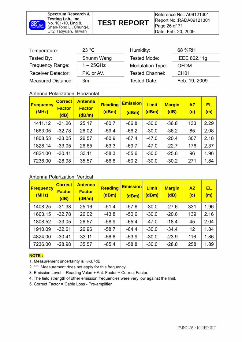
Temperature: 23 °C Humidity: 68 %RH Tested By: Shunm Wang Tested Mode: IEEE 802.11g Frequency Range: 1 – 25GHz Modulation Type: OFDM Receiver Detector: PK. or AV. Tested Channel: CH01 Measured Distance: 3m Tested Date: Feb. 19, 2009 Antenna Polarization: Horizontal
Frequency (MHz)
Correct Factor (dB)
Antenna Factor (dB/m)
Reading (dBm)
Emission
(dBm)
Limit (dBm)
Margin (dB)
AZ (o)
EL (m)
1411.12 -31.26 25.17 -60.7 -66.8 -30.0 -36.8 133 2.29 1663.05 -32.78 26.02 -59.4 -66.2 -30.0 -36.2 85 2.08 1808.53 -33.05 26.57 -60.9 -67.4 -47.0 -20.4 307 2.18 1828.14 -33.05 26.65 -63.3 -69.7 -47.0 -22.7 176 2.37 4824.00 -30.41 33.11 -58.3 -55.6 -30.0 -25.6 96 1.96 7236.00 -28.98 35.57 -66.8 -60.2 -30.0 -30.2 271 1.84
Antenna Polarization: Vertical
Frequency (MHz)
Correct Factor (dB)
Antenna Factor (dB/m)
Reading (dBm)
Emission
(dBm)
Limit (dBm)
Margin (dB)
AZ (o)
EL (m)
1408.25 -31.38 25.16 -51.4 -57.6 -30.0 -27.6 331 1.96 1663.15 -32.78 26.02 -43.8 -50.6 -30.0 -20.6 139 2.16 1808.52 -33.05 26.57 -58.9 -65.4 -47.0 -18.4 45 2.04 1910.09 -32.61 26.96 -58.7 -64.4 -30.0 -34.4 12 1.84 4824.00 -30.41 33.11 -56.6 -53.9 -30.0 -23.9 116 1.86 7236.00 -28.98 35.57 -65.4 -58.8 -30.0 -28.8 258 1.89
NOTE : 1. Measurement uncertainty is +/-3.7dB. 2. "*": Measurement does not apply for this frequency. 3. Emission Level = Reading Value + Ant. Factor + Correct Factor. 4. The field strength of other emission frequencies were very low against the limit. 5. Correct Factor = Cable Loss - Pre-amplifier.

Spectrum Research & Testing Lab., Inc. No. 101-10, Ling 8, Shan-Tong Li, Chung-Li City, Taoyuan, Taiwan
TEST REPORT Reference No.: A09121301 Report No.:RADA09121301 Page:27 of 71 Date: Feb. 20, 2009
FMNG-059.10 REPORT
Temperature: 23 °C Humidity: 68 %RH Tested By: Shunm Wang Tested Mode: IEEE 802.11g Frequency Range: 1 – 25GHz Modulation Type: OFDM Receiver Detector: PK. or AV. Tested Channel: CH06 Measured Distance: 3m Tested Date: Feb. 19, 2009 Antenna Polarization: Horizontal
Frequency (MHz)
Correct Factor (dB)
Antenna Factor (dB/m)
Reading (dBm)
Emission
(dBm)
Limit (dBm)
Margin (dB)
AZ (o)
EL (m)
1411.12 -31.26 25.17 -60.7 -66.8 -30.0 -36.8 143 2.26 1663.05 -32.78 26.02 -59.4 -66.2 -30.0 -36.2 85 2.05 1808.53 -33.05 26.57 -60.8 -67.3 -47.0 -20.3 302 2.17 1828.14 -33.05 26.65 -62.9 -69.3 -47.0 -22.3 175 2.36 4874.00 -30.28 33.22 -57.2 -54.3 -30.0 -24.3 103 1.97 7311.00 -29.07 35.72 -66.5 -59.8 -30.0 -29.8 279 1.90
Antenna Polarization: Vertical
Frequency (MHz)
Correct Factor (dB)
Antenna Factor (dB/m)
Reading (dBm)
Emission
(dBm)
Limit (dBm)
Margin (dB)
AZ (o)
EL (m)
1408.25 -31.38 25.16 -51.3 -57.5 -30.0 -27.5 321 1.99 1663.15 -32.78 26.02 -43.9 -50.7 -30.0 -20.7 150 2.15 1808.52 -33.05 26.57 -58.8 -65.3 -47.0 -18.3 41 2.06 1910.09 -32.61 26.96 -58.4 -64.1 -30.0 -34.1 24 1.85 4874.00 -30.28 33.22 -55.5 -52.6 -30.0 -22.6 119 1.86 7311.00 -29.07 35.72 -65.6 -58.9 -30.0 -28.9 265 1.90
NOTE : 1. Measurement uncertainty is +/-3.7dB. 2. "*": Measurement does not apply for this frequency. 3. Emission Level = Reading Value + Ant. Factor + Correct Factor. 4. The field strength of other emission frequencies were very low against the limit. 5. Correct Factor = Cable Loss - Pre-amplifier.

Spectrum Research & Testing Lab., Inc. No. 101-10, Ling 8, Shan-Tong Li, Chung-Li City, Taoyuan, Taiwan
TEST REPORT Reference No.: A09121301 Report No.:RADA09121301 Page:28 of 71 Date: Feb. 20, 2009
FMNG-059.10 REPORT
Temperature: 23 °C Humidity: 68 %RH Tested By: Shunm Wang Tested Mode: IEEE 802.11g Frequency Range: 1 – 25GHz Modulation Type: OFDM Receiver Detector: PK. or AV. Tested Channel: CH11 Measured Distance: 3m Tested Date: Feb. 19, 2009 Antenna Polarization: Horizontal
Frequency (MHz)
Correct Factor (dB)
Antenna Factor (dB/m)
Reading (dBm)
Emission
(dBm)
Limit (dBm)
Margin (dB)
AZ (o)
EL (m)
1411.12 -31.26 25.17 -60.7 -66.8 -30.0 -36.8 136 2.31 1663.05 -32.78 26.02 -59.8 -66.6 -30.0 -36.6 86 2.06 1808.53 -33.05 26.57 -60.5 -67.0 -47.0 -20.0 301 2.22 1828.14 -33.05 26.65 -62.9 -69.3 -47.0 -22.3 176 2.35 4924.00 -30.23 33.33 -57.7 -54.6 -30.0 -24.6 100 1.95 7386.00 -28.94 35.87 -65.8 -58.9 -30.0 -28.9 279 1.90
Antenna Polarization: Vertical
Frequency (MHz)
Correct Factor (dB)
Antenna Factor (dB/m)
Reading (dBm)
Emission
(dBm)
Limit (dBm)
Margin (dB)
AZ (o)
EL (m)
1408.25 -31.38 25.16 -51.2 -57.4 -30.0 -27.4 318 1.92 1663.15 -32.78 26.02 -44.3 -51.1 -30.0 -21.1 142 2.16 1808.52 -33.05 26.57 -58.5 -65.0 -47.0 -18.0 39 2.03 1910.09 -32.61 26.96 -58.7 -64.4 -30.0 -34.4 25 1.86 4924.00 -30.23 33.33 -54.6 -51.5 -30.0 -21.5 123 1.87 7386.00 -28.94 35.87 -65.4 -58.5 -30.0 -28.5 252 1.92
NOTE : 1. Measurement uncertainty is +/-3.7dB. 2. "*": Measurement does not apply for this frequency. 3. Emission Level = Reading Value + Ant. Factor + Correct Factor. 4. The field strength of other emission frequencies were very low against the limit. 5. Correct Factor = Cable Loss - Pre-amplifier.

Spectrum Research & Testing Lab., Inc. No. 101-10, Ling 8, Shan-Tong Li, Chung-Li City, Taoyuan, Taiwan
TEST REPORT Reference No.: A09121301 Report No.:RADA09121301 Page:29 of 71 Date: Feb. 20, 2009
FMNG-059.10 REPORT
Temperature: 23 °C Humidity: 68 %RH Tested By: Shunm Wang Tested Mode: IEEE 802.11b Frequency Range: 1 – 25GHz Modulation Type: CCK Receiver Detector: PK. or AV. Tested Channel: CH01 Measured Distance: 3m Tested Date: Feb. 19, 2009 Antenna Polarization: Horizontal
Frequency (MHz)
Correct Factor (dB)
Antenna Factor (dB/m)
Reading (dBm)
Emission
(dBm)
Limit (dBm)
Margin (dB)
AZ (o)
EL (m)
1411.12 -31.26 25.17 -60.5 -66.6 -30.0 -36.6 139 2.28 1663.05 -32.78 26.02 -59.6 -66.3 -30.0 -36.3 81 2.07 1808.53 -33.05 26.57 -60.8 -67.3 -47.0 -20.3 305 2.19 1828.14 -33.05 26.65 -63.1 -69.5 -47.0 -22.5 176 2.38 4824.00 -30.41 33.11 -56.2 -53.5 -30.0 -23.5 93 1.95 7236.00 -28.98 35.57 -64.9 -58.3 -30.0 -28.3 276 1.86
Antenna Polarization: Vertical
Frequency (MHz)
Correct Factor (dB)
Antenna Factor (dB/m)
Reading (dBm)
Emission
(dBm)
Limit (dBm)
Margin (dB)
AZ (o)
EL (m)
1408.25 -31.38 25.16 -51.2 -57.4 -30.0 -27.4 329 1.95 1663.15 -32.78 26.02 -44.0 -50.8 -30.0 -20.8 143 2.17 1808.52 -33.05 26.57 -58.7 -65.2 -47.0 -18.2 43 2.05 1910.09 -32.61 26.96 -58.5 -64.1 -30.0 -34.1 19 1.82 4824.00 -30.41 33.11 -54.1 -51.4 -30.0 -21.4 109 1.85 7236.00 -28.98 35.57 -63.6 -57.0 -30.0 -27.0 261 1.91
NOTE : 1. Measurement uncertainty is +/-3.7dB. 2. "*": Measurement does not apply for this frequency. 3. Emission Level = Reading Value + Ant. Factor + Correct Factor. 4. The field strength of other emission frequencies were very low against the limit. 5. Correct Factor = Cable Loss - Pre-amplifier.

Spectrum Research & Testing Lab., Inc. No. 101-10, Ling 8, Shan-Tong Li, Chung-Li City, Taoyuan, Taiwan
TEST REPORT Reference No.: A09121301 Report No.:RADA09121301 Page:30 of 71 Date: Feb. 20, 2009
FMNG-059.10 REPORT
Temperature: 23 °C Humidity: 68 %RH Tested By: Shunm Wang Tested Mode: IEEE 802.11b Frequency Range: 1 – 25GHz Modulation Type: CCK Receiver Detector: PK. or AV. Tested Channel: CH06 Measured Distance: 3m Tested Date: Feb. 19, 2009 Antenna Polarization: Horizontal
Frequency (MHz)
Correct Factor (dB)
Antenna Factor (dB/m)
Reading (dBm)
Emission
(dBm)
Limit (dBm)
Margin (dB)
AZ (o)
EL (m)
1411.12 -31.26 25.17 -60.6 -66.7 -30.0 -36.7 142 2.27 1663.05 -32.78 26.02 -59.5 -66.3 -30.0 -36.3 83 2.06 1808.53 -33.05 26.57 -60.7 -67.2 -47.0 -20.2 301 2.18 1828.14 -33.05 26.65 -63.0 -69.4 -47.0 -22.4 179 2.37 4874.00 -30.28 33.22 -55.9 -53.0 -30.0 -23.0 95 1.96 7311.00 -29.07 35.72 -64.6 -57.9 -30.0 -27.9 275 1.87
Antenna Polarization: Vertical
Frequency (MHz)
Correct Factor (dB)
Antenna Factor (dB/m)
Reading (dBm)
Emission
(dBm)
Limit (dBm)
Margin (dB)
AZ (o)
EL (m)
1408.25 -31.38 25.16 -51.2 -57.4 -30.0 -27.4 324 1.96 1663.15 -32.78 26.02 -44.0 -50.8 -30.0 -20.8 146 2.16 1808.52 -33.05 26.57 -58.7 -65.2 -47.0 -18.2 45 2.04 1910.09 -32.61 26.96 -58.5 -64.1 -30.0 -34.1 22 1.83 4874.00 -30.28 33.22 -53.8 -50.9 -30.0 -20.9 112 1.84 7311.00 -29.07 35.72 -63.3 -56.6 -30.0 -26.6 263 1.92
NOTE : 1. Measurement uncertainty is +/-3.7dB. 2. "*": Measurement does not apply for this frequency. 3. Emission Level = Reading Value + Ant. Factor + Correct Factor. 4. The field strength of other emission frequencies were very low against the limit. 5. Correct Factor = Cable Loss - Pre-amplifier.

Spectrum Research & Testing Lab., Inc. No. 101-10, Ling 8, Shan-Tong Li, Chung-Li City, Taoyuan, Taiwan
TEST REPORT Reference No.: A09121301 Report No.:RADA09121301 Page:31 of 71 Date: Feb. 20, 2009
FMNG-059.10 REPORT
Temperature: 23 °C Humidity: 68 %RH Tested By: Shunm Wang Tested Mode: IEEE 802.11b Frequency Range: 1 – 25GHz Modulation Type: CCK Receiver Detector: PK. or AV. Tested Channel: CH11 Measured Distance: 3m Tested Date: Feb. 19, 2009 Antenna Polarization: Horizontal
Frequency (MHz)
Correct Factor (dB)
Antenna Factor (dB/m)
Reading (dBm)
Emission
(dBm)
Limit (dBm)
Margin (dB)
AZ (o)
EL (m)
1411.12 -31.26 25.17 -60.6 -66.7 -30.0 -36.7 141 2.32 1663.05 -32.78 26.02 -59.7 -66.5 -30.0 -36.5 86 2.05 1808.53 -33.05 26.57 -60.6 -67.1 -47.0 -20.1 308 2.21 1828.14 -33.05 26.65 -63.0 -69.4 -47.0 -22.4 175 2.36 4924.00 -30.23 33.33 -55.7 -52.6 -30.0 -22.6 90 1.96 7386.00 -28.94 35.87 -64.4 -57.5 -30.0 -27.5 276 1.89
Antenna Polarization: Vertical
Frequency (MHz)
Correct Factor (dB)
Antenna Factor (dB/m)
Reading (dBm)
Emission
(dBm)
Limit (dBm)
Margin (dB)
AZ (o)
EL (m)
1408.25 -31.38 25.16 -51.3 -57.5 -30.0 -27.5 322 1.93 1663.15 -32.78 26.02 -44.1 -50.9 -30.0 -20.9 145 2.15 1808.52 -33.05 26.57 -58.6 -65.1 -47.0 -18.1 38 2.04 1910.09 -32.61 26.96 -58.4 -64.1 -30.0 -34.1 22 1.84 4924.00 -30.23 33.33 -53.6 -50.5 -30.0 -20.5 115 1.89 7386.00 -28.94 35.87 -63.3 -56.4 -30.0 -26.4 261 1.93
NOTE : 1. Measurement uncertainty is +/-3.7dB. 2. "*": Measurement does not apply for this frequency. 3. Emission Level = Reading Value + Ant. Factor + Correct Factor. 4. The field strength of other emission frequencies were very low against the limit. 5. Correct Factor = Cable Loss - Pre-amplifier.

Spectrum Research & Testing Lab., Inc. No. 101-10, Ling 8, Shan-Tong Li, Chung-Li City, Taoyuan, Taiwan
TEST REPORT Reference No.: A09121301 Report No.:RADA09121301 Page:32 of 71 Date: Feb. 20, 2009
FMNG-059.10 REPORT
5. CONDUCTED EMISSION TEST 5.1 LIMIT
Class A (dBµV) Class B (dBµV) Frequency (MHz) Quasi-peak Average Quasi-peak Average 0.15 - 0.5 79 66 66 - 56 56 - 46 0.50 - 5.0 73 60 56 46 5.0 - 30.0 73 60 60 50
NOTE :
1. The lower limit shall apply at the transition frequencies.
2. The limit decreases in line with the logarithm of the frequency in the range of 0.15 to 0.50 MHz.
5.2 TEST EQUIPMENT
The following test equipment was used for the test:
EQUIPMENT/ FACILITIES
SPECIFICATIONS MANUFACTURERMODEL#/ SERIAL#
DUE DATE OF CAL. & CAL. CENTER
EMI TEST
RECEIVER
9 kHz TO
30 MHz
ROHDE &
SCHWARZ
ESHS30 /
826003/008
SEP. 2009
ETC
LISN 50 µH, 50 ohm FCC FCC-LISN-50-25-2 /
01017
OCT. 2009
ETC
LISN 50µH, 50 ohm FCC 9252-50-R24-BNC /
951315
JUN. 2009
ETC
50 OHM
TERMINATOR 50 ohm HP
11593A /
#2
OCT. 2009
ETC
COAXIAL CABLE 5M TIMES EQM-0159 /
#5-5m
AUG. 2009
SRT
FILTER 2 LINE, 30A FIL.COIL FC-943 /
771 NCR
GROUND PLANE 2.3M (H) x
2.4M (W) SRT N/A NCR
GROUND PLANE 2.4M (H) x
2.4M (W) SRT N/A NCR
NOTE: The calibration interval of the above test equipment is one year and the calibrations are traceable to NML/ROC and NIST/USA.

Spectrum Research & Testing Lab., Inc. No. 101-10, Ling 8, Shan-Tong Li, Chung-Li City, Taoyuan, Taiwan
TEST REPORT Reference No.: A09121301 Report No.:RADA09121301 Page:33 of 71 Date: Feb. 20, 2009
FMNG-059.10 REPORT
5.3 TEST PROCEDURE According to EN 55022:2006, EN 301 489-17 V1.3.2: 2008.
5.4 TEST SETUP
NOTE: 1. The EUT was put on a wooden table with 0.8m heights above ground plane, and 0.4m away from reference ground plane (> 2mx2m). 2. For the actual test configuration, please refer to the photos of testing. 3. The serial no. of the LISN connected to EUT is 01017. 4. The serial no. of the LISN connected to support units is 01018.

Spectrum Research & Testing Lab., Inc. No. 101-10, Ling 8, Shan-Tong Li, Chung-Li City, Taoyuan, Taiwan
TEST REPORT Reference No.: A09121301 Report No.:RADA09121301 Page:34 of 71 Date: Feb. 20, 2009
FMNG-059.10 REPORT
5.5 TEST RESULT Temperature: 22 °C Humidity: 58 %RH Frequency Range: 0.15 – 30 MHz Tested Mode: Standby Receiver Detector: Q.P. and AV. Modulation Type: N/A Tested By: Shunm Wang Tested Channel: N/A Tested Date: Feb. 17, 2009
Power Line Measured : Line
Reading Value(dBμV)
Emission Level(dBμV)
Limit (dBμV)
Margin (dB)
Freq. (MHz)
Correct. Factor (dB) Q.P. AV. Q.P. AV. Q.P. AV. Q.P. AV.
0.495 0.25 38.76 29.88 39.01 30.13 56.07 46.07 -17.06 -15.94 0.501 0.24 38.06 26.80 38.30 27.04 56.00 46.00 -17.70 -18.96 0.624 0.22 39.62 27.89 39.84 28.11 56.00 46.00 -16.16 -17.89 1.586 0.15 39.10 28.35 39.25 28.50 56.00 46.00 -16.75 -17.50 2.220 0.16 36.10 25.41 36.26 25.57 56.00 46.00 -19.74 -20.43 25.691 0.40 33.06 26.85 33.46 27.25 60.00 50.00 -26.54 -22.75
Power Line Measured : Neutral
Reading Value(dBμV)
Emission Level(dBμV)
Limit (dBμV)
Margin (dB)
Freq. (MHz)
Correct. Factor (dB) Q.P. AV. Q.P. AV. Q.P. AV. Q.P. AV.
0.189 0.30 44.38 35.13 44.68 35.43 64.06 54.06 -19.38 -18.63 0.492 0.25 36.42 30.07 36.67 30.32 56.12 46.12 -19.45 -15.80 0.615 0.22 41.08 32.95 41.30 33.17 56.00 46.00 -14.70 -12.83 1.537 0.15 35.34 25.97 35.49 26.12 56.00 46.00 -20.51 -19.88 3.437 0.19 33.22 24.22 33.41 24.41 56.00 46.00 -22.59 -21.59 23.846 0.29 32.74 26.33 33.03 26.62 60.00 50.00 -26.97 -23.38
NOTE :
1. Measurement uncertainty is +/- 2dB 2. Emission level = Reading valus + Correction factor 3. Correction Factor = Cable loss + Insertion loss of LISN 4. Margin value = Emission level - Limit 5. The emission of other frequencies was very low against the limit. 6. "-": The Quasi-peak reading value also meets average limit and measurement with the average
detector is unnecessary.

Spectrum Research & Testing Lab., Inc. No. 101-10, Ling 8, Shan-Tong Li, Chung-Li City, Taoyuan, Taiwan
TEST REPORT Reference No.: A09121301 Report No.:RADA09121301 Page:35 of 71 Date: Feb. 20, 2009
FMNG-059.10 REPORT
Temperature: 22 °C Humidity: 58 %RH Frequency Range: 0.15 – 30 MHz Tested Mode: Link Receiver Detector: Q.P. and AV. Modulation Type: N/A Tested By: Shunm Wang Tested Channel: N/A Tested Date: Feb. 17, 2009
Power Line Measured : Line
Reading Value(dBμV)
Emission Level(dBμV)
Limit (dBμV)
Margin (dB)
Freq. (MHz)
Correct. Factor (dB) Q.P. AV. Q.P. AV. Q.P. AV. Q.P. AV.
0.492 0.25 39.06 31.72 39.31 31.97 56.12 46.12 -16.81 -14.15 0.501 0.24 37.96 24.46 38.20 24.70 56.00 46.00 -17.80 -21.30 0.778 0.20 32.14 18.54 32.34 18.74 56.00 46.00 -23.66 -27.26 1.655 0.15 38.38 31.17 38.53 31.32 56.00 46.00 -17.47 -14.68 2.269 0.16 37.52 27.60 37.68 27.76 56.00 46.00 -18.32 -18.24 5.335 0.22 33.24 27.25 33.46 27.47 60.00 50.00 -26.54 -22.53
Power Line Measured : Neutral
Reading Value(dBμV)
Emission Level(dBμV)
Limit (dBμV)
Margin (dB)
Freq. (MHz)
Correct. Factor (dB) Q.P. AV. Q.P. AV. Q.P. AV. Q.P. AV.
0.183 0.30 46.52 41.51 46.82 41.81 64.33 54.33 -17.51 -12.52 0.486 0.25 36.20 31.69 36.45 31.94 56.22 46.22 -19.77 -14.28 0.610 0.22 40.40 34.40 40.62 34.62 56.00 46.00 -15.38 -11.38 2.240 0.16 35.24 25.65 35.40 25.81 56.00 46.00 -20.60 -20.19 4.160 0.20 35.00 24.61 35.20 24.81 56.00 46.00 -20.80 -21.19 24.799 0.29 32.96 26.07 33.25 26.36 60.00 50.00 -26.75 -23.64
NOTE :
1. Measurement uncertainty is +/- 2dB 2. Emission level = Reading valus + Correction factor 3. Correction Factor = Cable loss + Insertion loss of LISN 4. Margin value = Emission level - Limit 5. The emission of other frequencies was very low against the limit. 6. "-": The Quasi-peak reading value also meets average limit and measurement with the average
detector is unnecessary.

Spectrum Research & Testing Lab., Inc. No. 101-10, Ling 8, Shan-Tong Li, Chung-Li City, Taoyuan, Taiwan
TEST REPORT Reference No.: A09121301 Report No.:RADA09121301 Page:36 of 71 Date: Feb. 20, 2009
FMNG-059.10 REPORT
Temperature: 22 °C Humidity: 58 %RH Frequency Range: 0.15 – 30 MHz Tested Mode: Tx Receiver Detector: Q.P. and AV. Modulation Type: OFDM Tested By: Shunm Wang Tested Channel: CH 11 Tested Date: Feb. 17, 2009
Power Line Measured : Line
Reading Value(dBμV)
Emission Level(dBμV)
Limit (dBμV)
Margin (dB)
Freq. (MHz)
Correct. Factor (dB) Q.P. AV. Q.P. AV. Q.P. AV. Q.P. AV.
0.495 0.25 39.24 30.23 39.49 30.48 56.07 46.07 -16.58 -15.59 0.501 0.24 38.20 26.79 38.44 27.03 56.00 46.00 -17.56 -18.97 0.620 0.22 39.86 28.93 40.08 29.15 56.00 46.00 -15.92 -16.85 1.576 0.15 39.20 31.55 39.35 31.70 56.00 46.00 -16.65 -14.30 2.200 0.16 37.84 28.97 38.00 29.13 56.00 46.00 -18.00 -16.87 23.815 0.39 32.78 26.25 33.17 26.64 60.00 50.00 -26.83 -23.36
Power Line Measured : Neutral
Reading Value(dBμV)
Emission Level(dBμV)
Limit (dBμV)
Margin (dB)
Freq. (MHz)
Correct. Factor (dB) Q.P. AV. Q.P. AV. Q.P. AV. Q.P. AV.
0.186 0.30 45.04 39.87 45.34 40.17 64.20 54.20 -18.86 -14.03 0.492 0.25 37.10 28.74 37.35 28.99 56.12 46.12 -18.77 -17.13 0.615 0.22 40.64 32.54 40.86 32.76 56.00 46.00 -15.14 -13.24 1.507 0.15 34.98 27.45 35.13 27.60 56.00 46.00 -20.87 -18.40 3.794 0.19 31.56 20.77 31.75 20.96 56.00 46.00 -24.25 -25.04 24.656 0.29 32.26 25.86 32.55 26.15 60.00 50.00 -27.45 -23.85
NOTE :
1. Measurement uncertainty is +/- 2dB 2. Emission level = Reading valus + Correction factor 3. Correction Factor = Cable loss + Insertion loss of LISN 4. Margin value = Emission level - Limit 5. The emission of other frequencies was very low against the limit. 6. "-": The Quasi-peak reading value also meets average limit and measurement with the average
detector is unnecessary.

Spectrum Research & Testing Lab., Inc. No. 101-10, Ling 8, Shan-Tong Li, Chung-Li City, Taoyuan, Taiwan
TEST REPORT Reference No.: A09121301 Report No.:RADA09121301 Page:37 of 71 Date: Feb. 20, 2009
FMNG-059.10 REPORT
Temperature: 22 °C Humidity: 58 %RH Frequency Range: 0.15 – 30 MHz Tested Mode: Tx Receiver Detector: Q.P. and AV. Modulation Type: CCK Tested By: Shunm Wang Tested Channel: CH 11 Tested Date: Feb. 17, 2009
Power Line Measured : Line
Reading Value(dBμV)
Emission Level(dBμV)
Limit (dBμV)
Margin (dB)
Freq. (MHz)
Correct. Factor (dB) Q.P. AV. Q.P. AV. Q.P. AV. Q.P. AV.
0.489 0.25 38.92 35.10 39.17 35.35 56.17 46.17 -17.00 -10.82 0.498 0.25 38.46 27.04 38.71 27.29 56.02 46.02 -17.31 -18.73 0.624 0.22 40.36 25.17 40.58 25.39 56.00 46.00 -15.42 -20.61 1.517 0.15 39.30 32.56 39.45 32.71 56.00 46.00 -16.55 -13.29 2.180 0.16 38.32 32.11 38.48 32.27 56.00 46.00 -17.52 -13.73 17.685 0.32 34.62 30.15 34.94 30.47 60.00 50.00 -25.06 -19.53
Power Line Measured : Neutral
Reading Value(dBμV)
Emission Level(dBμV)
Limit (dBμV)
Margin (dB)
Freq. (MHz)
Correct. Factor (dB) Q.P. AV. Q.P. AV. Q.P. AV. Q.P. AV.
0.186 0.30 45.00 39.79 45.30 40.09 64.20 54.20 -18.90 -14.11 0.492 0.25 37.94 31.30 38.19 31.55 56.12 46.12 -17.93 -14.57 0.610 0.22 41.76 35.34 41.98 35.56 56.00 46.00 -14.02 -10.44 2.913 0.18 36.48 30.05 36.66 30.23 56.00 46.00 -19.34 -15.77 4.180 0.20 34.46 26.72 34.66 26.92 56.00 46.00 -21.34 -19.08 24.871 0.29 32.82 26.36 33.11 26.65 60.00 50.00 -26.89 -23.35
NOTE :
1. Measurement uncertainty is +/- 2dB 2. Emission level = Reading valus + Correction factor 3. Correction Factor = Cable loss + Insertion loss of LISN 4. Margin value = Emission level - Limit 5. The emission of other frequencies was very low against the limit. 6. "-": The Quasi-peak reading value also meets average limit and measurement with the average
detector is unnecessary.
Spectrum Research & Testing Lab., Inc. No. 101-10, Ling 8, Shan-Tong Li, Chung-Li City, Taoyuan, Taiwan
TEST REPORT Reference No.: A09121301 Report No.:RADA09121301 Page:38 of 71 Date: Feb. 20, 2009
FMNG-059.10 REPORT
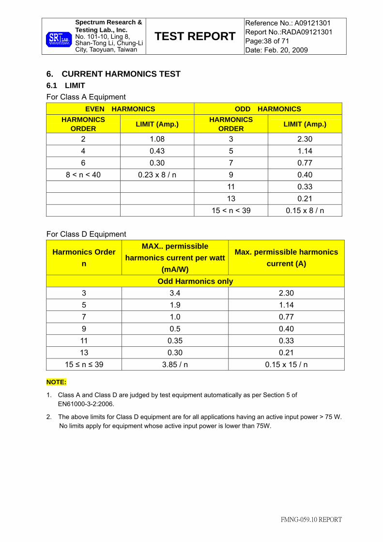
6. CURRENT HARMONICS TEST 6.1 LIMIT For Class A Equipment
EVEN HARMONICS ODD HARMONICS HARMONICS
ORDER LIMIT (Amp.) HARMONICS ORDER LIMIT (Amp.)
2 1.08 3 2.30 4 0.43 5 1.14 6 0.30 7 0.77
8 < n < 40 0.23 x 8 / n 9 0.40 11 0.33 13 0.21 15 < n < 39 0.15 x 8 / n
For Class D Equipment
Harmonics Order n
MAX.. permissible harmonics current per watt
(mA/W)
Max. permissible harmonics current (A)
Odd Harmonics only 3 3.4 2.30 5 1.9 1.14 7 1.0 0.77 9 0.5 0.40 11 0.35 0.33 13 0.30 0.21
15 ≤ n ≤ 39 3.85 / n 0.15 x 15 / n
NOTE:
1. Class A and Class D are judged by test equipment automatically as per Section 5 of EN61000-3-2:2006.
2. The above limits for Class D equipment are for all applications having an active input power > 75 W. No limits apply for equipment whose active input power is lower than 75W.

Spectrum Research & Testing Lab., Inc. No. 101-10, Ling 8, Shan-Tong Li, Chung-Li City, Taoyuan, Taiwan
TEST REPORT Reference No.: A09121301 Report No.:RADA09121301 Page:39 of 71 Date: Feb. 20, 2009
FMNG-059.10 REPORT
6.2 TEST EQUIPMENT
EQUIPMENT / FACILITIES MANUFACTURER MODEL # / SERIAL #
DUE DATE OF CAL. & CAL. CENTER
Harmonic/Flicker-Test System EMC PARTNER HAR-1000-1P / 081 AUG. 2009 ETC
6.3 TEST SETUP
NOTE : 1. The EUT system was put on a wooden table with 0.8m high. 2. For the actual test configuration, please refer to the photos of testing.
6.4 TEST PROCEDURE
According to EN 61000-3-2:2006 , EN 301 489-01 V1.8.1:2008
6.5 DESCRIPTION OF SUPPORT UNIT
Same as section 2.4 of this report. 6.6 EUT OPERATING CONDITION
Same as section 2.5 of this report.
Auxiliary
Equipment EUT
Harmonics/
Flicker tester
To utility power
Spectrum Research & Testing Lab., Inc. No. 101-10, Ling 8, Shan-Tong Li, Chung-Li City, Taoyuan, Taiwan
TEST REPORT Reference No.: A09121301 Report No.:RADA09121301 Page:40 of 71 Date: Feb. 20, 2009
FMNG-059.10 REPORT
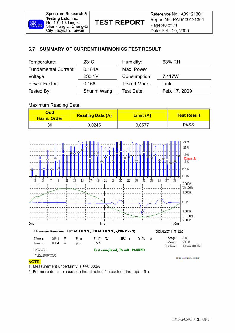
6.7 SUMMARY OF CURRENT HARMONICS TEST RESULT Temperature: 23°C Humidity: 63% RH Fundamental Current: Voltage:
0.184A 233.1V
Max. Power Consumption:
7.117W
Power Factor: 0.166 Tested Mode: Link Tested By: Shunm Wang Test Date: Feb. 17, 2009 Maximum Reading Data:
Odd Harm. Order Reading Data (A) Limit (A) Test Result
39 0.0245 0.0577 PASS
NOTE: 1. Measurement uncertainty is +/-0.003A 2. For more detail, please see the attached file back on the report file.

Spectrum Research & Testing Lab., Inc. No. 101-10, Ling 8, Shan-Tong Li, Chung-Li City, Taoyuan, Taiwan
TEST REPORT Reference No.: A09121301 Report No.:RADA09121301 Page:41 of 71 Date: Feb. 20, 2009
FMNG-059.10 REPORT
7. VOLTAGE FLUCTUATIONS 7.1 LIMIT Short-team flicker (Pst) : 1.0 Long-term flicker (Plt) : 0.65 Relative steady-state voltage change (Dc) : ≤ 3.3% Relative voltage change characteristic (D (t) ) > 3.3% ; (TD(t)) : ≤ 500 ms Maximum relative voltage change (Dmax) : ≤ 4%
TEST ITEM LIMIT NOTE Pst 1.0 Pst means short-term flicker indicator. Plt 0.65 Plt means long-term flicker indicator.
TD(t) (ms) 500 TD(t) means maximum time that D (t) exceeds 3.3 %.Dmax (%) 4% Dmax means maximum relative voltage change. Dc (%) 3.3% Dc means relative steady-state voltage change
7.2 TEST EQUIPMENT
EQUIPMENT / FACILITIES MANUFACTURERMODEL # / SERIAL #
DUE DATE OF CAL. & CAL. CENTER
Harmonic/Flicker-Test System EMC PARTNER HAR-1000-1P / 081 AUG. 2009 ETC
7.3 TEST PROCEDURE According to EN 61000-3-3:1995+A1:2001+A2:2005 , EN 301 489-01 V1.8.1:2008. 7.4 TEST SETUP NOTE : 1. The EUT system was put on a wooden table with 0.8m high.
2. For the actual test configuration, please refer to the photos of testing.
7.5 DESCRIPTION OF SUPPORT UNIT Same as section 2.4 of this report. 7.6 EUT OPERATING CONDITION Same as section 2.5 of this report.
Auxiliary
Equipment EUT
Harmonics/
Flicker tester
To utility power

Spectrum Research & Testing Lab., Inc. No. 101-10, Ling 8, Shan-Tong Li, Chung-Li City, Taoyuan, Taiwan
TEST REPORT Reference No.: A09121301 Report No.:RADA09121301 Page:42 of 71 Date: Feb. 20, 2009
FMNG-059.10 REPORT
7.7 SUMMARY OF VOLTAGE FLUCTUATIONS TEST RESULT
Temperature: 23°C Humidity: 63% RH Input Voltage: Ampere:
232.9Vrms 0.171Ams
Observation Period:
2Hr
Power Factor: 0.387 Tested Mode: Link Tested By: Shunm Wang Test Date: Feb. 17, 2009 Test Result:
TEST PARAMETER MEASUREMENT VALUE LIMIT TEST RESULT
Pst 0.07 1.0 PASS Plt 0.07 0.65 PASS
TD(t) (ms) 0 500 PASS Dmax (%) 0.00% 4% PASS Dc (%) 0.06% 3.30% PASS
NOTE: 1. Pst means short-term flicker indicator. 2. Plt means long-term flicker indicator. 3. TD(t) means maximum time that D(t) exceeds 3.3 %. 4. Dmax means maximum relative voltage change. 5. Dc means relative steady-state voltage change. 6. N/A: Not applicable.. 7. Measurement uncertainty:
(1) Pst: +/-0.02P.U. (2) Plt: +/-0.02P.U. (3). TD(t) : +/-0.02ms (4) Dmax :+/-0. 02%(5).Dc: +/-0.02%. 8. For more detail, please see the attached file back on the report file.

Spectrum Research & Testing Lab., Inc. No. 101-10, Ling 8, Shan-Tong Li, Chung-Li City, Taoyuan, Taiwan
TEST REPORT Reference No.: A09121301 Report No.:RADA09121301 Page:43 of 71 Date: Feb. 20, 2009
FMNG-059.10 REPORT
8. ELECTROSTATIC DISCHARGE 8.1 TEST EQUIPMENT
EQUIPMENT / FACILITIES
MANUFACTURERMODEL # / SERIAL #
DUE DATE OF CAL. & CAL. CENTER
ESD SIMULATOR NOISEKEN ESS-100L(A)/TC-815P / 8099C02238/7099C02
NOV. 2009 ETC
HCP (1.6M x 0.8M) SRT WITH TWO 470k OHM CABLE
NCR
VCP (0.5M x 0.5M) SRT WITH TWO 470k OHM CABLE
NCR
GROUND PLANE (3.4M x 2.4M)
SRT N/A NCR
NOTE: The calibration interval of the above test equipment is one year and the calibrations are traceable to NML/ROC and NIST/USA.
8.2 TEST PROCEDURE
According to EN 301 489-01 V1.8.1:2008, EN 301 489-17 V1.3.2:2008.

Spectrum Research & Testing Lab., Inc. No. 101-10, Ling 8, Shan-Tong Li, Chung-Li City, Taoyuan, Taiwan
TEST REPORT Reference No.: A09121301 Report No.:RADA09121301 Page:44 of 71 Date: Feb. 20, 2009
FMNG-059.10 REPORT
8.3 TEST SET-UP
NOTE : 1. The wooden table should be 0.8m high for table top EUT and 01.m for floor-standing EUT. 2. For the actual test configuration, please refer to the photos of testing. 3. A distance of 1m minimum was provided between EUT and walls / other metallic structure.
Insulating Support
ESD Gun
Return
Cable
EUT System
Vertical Coupling Plane
Ground Reference Plane
Horizontal Coupling
Plane
Wooden Table
470kΩ
470kΩ
10 cm

Spectrum Research & Testing Lab., Inc. No. 101-10, Ling 8, Shan-Tong Li, Chung-Li City, Taoyuan, Taiwan
TEST REPORT Reference No.: A09121301 Report No.:RADA09121301 Page:45 of 71 Date: Feb. 20, 2009
FMNG-059.10 REPORT
8.4 TEST CONDITION AND PERFORMANCE 1. Test condition:
(1) R-C Network: 330ohm, 150pF (2) Test level: Air Discharge: ±2kV, ±4kV, ±8kV
Contact discharge: ±2kV, ±4kV Hcp discharge : ±2kV, ±4kV Vcp discharge : ±2kV, ±4kV
(3) Discharge mode : Single discharge (4) Discharge period: at least 1 second (5) Discharge polarity : Postive and Negative (6) Number of discharge: Minimum 50 times at each test point of contact
disdarge and at least 200 times of contact discharge to EUT in total. Minimum 10 times at each test area of air discharge selected.
2. Standard requirement: Criterion B
8.5 GENERAL PERFORMANCE CRITERIA DESCRIPTION
CLASSIFICATION OF SRD EQUIPMET Class of SRD
equipment Risk assessment of receiver performance
1 Highly reliable SRD communication media; e.g. serving human life inherent systems(may result in a physical risk to a person)
2 Medium reliable SRD communication media; e.g. causing inconvenience to persons, which cannot simply be overcome by other means.
3 Standard reliable SRD communication media; e.g. inconvenience to persons, which can simply be overcome by other means (e.g. manual)

Spectrum Research & Testing Lab., Inc. No. 101-10, Ling 8, Shan-Tong Li, Chung-Li City, Taoyuan, Taiwan
TEST REPORT Reference No.: A09121301 Report No.:RADA09121301 Page:46 of 71 Date: Feb. 20, 2009
FMNG-059.10 REPORT
The Requirement of Performance Criteria
1
Performance criteria for continuous phenomena applied to transmitters (CT)
Criterion A of the applicable class shall apply
2 Performance criteria for transient phenomena applied to transmitters (TT)
Criterion B of the applicable class shall apply
3 Performance criteria for continuous phenomena applied to receivers (CR)
Criterion A of the applicable class shall apply
4 Performance criteria for transient phenomena applied to receivers (TR)
Criterion B of the applicable class shall apply
The phenomena allowed during and after test in each criterion are clearly stated in the following table
Class 1 SRD equipment
Criteria During test After test
A
Operate as intended. No loss of function. For equipment type II the minimum performance shall be 12dB SINAD No unintentional responses
Operate as intended. For equipment type II the communication link shall be maintained No loss of function No degradation of performance No loss of stored data or user programmable functions
B
May be loss of function (one or more)No unintentional responses
Operate as intended Lost function(s) shall be self-recoverable No degradation of performance No loss of stored data or user programmable functions

Spectrum Research & Testing Lab., Inc. No. 101-10, Ling 8, Shan-Tong Li, Chung-Li City, Taoyuan, Taiwan
TEST REPORT Reference No.: A09121301 Report No.:RADA09121301 Page:47 of 71 Date: Feb. 20, 2009
FMNG-059.10 REPORT
Class 2 SRD equipment
Criteria During test After test
A
Operate as intended. No loss of function. For equipment type II the minimum performance shall be 6dB SINAD
No unintentional responses
Operate as intended. For equipment type II the communication link shall be maintained No loss of function No degradation of performance No loss of stored data or user programmable functions
B May be loss of function (one or more)No unintentional responses
Operate as intended Lost function(s) shall be self-recoverable No degradation of performance No loss of stored data or user programmable functions
Class 3 SRD equipment
Criteria During test After test
A and B May be loss of function (one or more)No unintentional responses
Operate as intended, for equipment type II the communication link may be lost, but shall be recoverable by user No degradation of performance Lost functions shall be self-recoverable

Spectrum Research & Testing Lab., Inc. No. 101-10, Ling 8, Shan-Tong Li, Chung-Li City, Taoyuan, Taiwan
TEST REPORT Reference No.: A09121301 Report No.:RADA09121301 Page:48 of 71 Date: Feb. 20, 2009
FMNG-059.10 REPORT
8.6 TEST RESULT Temperature: 24 °C Humidity: 55 % RH Tested Mode: Link Tested By: Shunm Wang Atmospheric Air Pressure: 101.2 kPa Tested Date: Feb. 18, 2009
Test Result: Criterion A pass COUPLING MODE & TEST OBSERVATION SEVERITY
LEVEL AIR DISCHARGE
CONTACT DISCHARGE HCP VCP
±2kV A A
±4kV A
±8kV A NOTE: Description of test observation: A: There was no change compared with initial operation during the test. NR: No requirement. Description of test points: 1. HCP. ( 4 Sides ) 2. VCP. ( 4 Sides ) 3. Screw 4. Case 5. Antenna

Spectrum Research & Testing Lab., Inc. No. 101-10, Ling 8, Shan-Tong Li, Chung-Li City, Taoyuan, Taiwan
TEST REPORT Reference No.: A09121301 Report No.:RADA09121301 Page:49 of 71 Date: Feb. 20, 2009
FMNG-059.10 REPORT
9. RADIATED IMMUNITY TEST
9.1 TEST EQUIPMENT
EQUIPMENT / FACILITIES MANUFACTURER MODEL # /
SERIAL # DUE DATE OF CAL.
& CAL. CENTER
SIGNAL GENERATOR R&S SMY01 / 841104/019
JUL. 2009 ETC
ANTENNA SCHAFFNER CHASECBL6141A / 4181
OCT. 2009 SRT
FIELD SENSOR AMPLIFIER RESEARCH
FP2000 / 28499
MAR. 2009 ITRI
POWER AMPLIFIER AMPLIFIER RESEARCH
100W1000M1 / 19509
NCR
AMPLIFIER A.R. 50S1G4A / 308703
NCR
DUAL DIRECTIONAL COUPLER
A.R. DC7420 / 308626
JUL. 2009 ETC.
ISOTROPIC “E” FIELD PROBE A.R. FP4080 KIT / 308105
JUL. 2009 ITRI
POWER SENSOR BOONTON 51015(SE) / 32966
JAN. 2010 ETC
POWER SENSOR BOONTON 51015(SE) / 32964
JAN. 2010 ETC
DUAL DIRECTIONAL COUPLER
A.R. DC6080 / 310289
JUL. 2009 ETC
ANECHOIC CHAMBER SRT A05 / SRT005
NOV. 2009 SRT
ISOTROPIC FIELD MONITOR
A.R. FM2000 / 15970
NCR
MONITOR TAYAMA 17582430 / NCR
CCD TOPVIEW N/A / 95113762
NCR
ABSORBER ETS N/A NCR
COAXIAL CABLE TIMES LMR400 / 0.5M
AUG. 2009 SRT
COAXIAL CABLE TIMES LMR400 / 4M
AUG. 2009 SRT
NOTE: The calibration interval of the above test equipment is one year and the calibrations are traceable to NML/ROC and NIST/USA.

Spectrum Research & Testing Lab., Inc. No. 101-10, Ling 8, Shan-Tong Li, Chung-Li City, Taoyuan, Taiwan
TEST REPORT Reference No.: A09121301 Report No.:RADA09121301 Page:50 of 71 Date: Feb. 20, 2009
FMNG-059.10 REPORT
9.2 TEST PROCEDURE According to EN 301 489-01 V1.8.1:2008, EN 301 489-17 V1.3.2:2008. 9.3 TEST SETUP NOTE : 1. The wooden table should be 0.8m high for table top EUT and 0.1m for floor-standing EUT. 2. For the actual test configuration, please refer to the photos of testing.
Absorber
Optical Fiber
Coaxial Cable
Power
Amplifier Signal Generator
V/M
MonitorMonitor
3 m
Sensor
Wooden
table
EUTCCD
Absorber
1.5m
0.8 m

Spectrum Research & Testing Lab., Inc. No. 101-10, Ling 8, Shan-Tong Li, Chung-Li City, Taoyuan, Taiwan
TEST REPORT Reference No.: A09121301 Report No.:RADA09121301 Page:51 of 71 Date: Feb. 20, 2009
FMNG-059.10 REPORT
1.1m door balun to Absorber/Tile
Ant. 2.75m Absorber Location 1.5m 2.2m 1.85m 0.24m chamber (7m x 3m x 3m)
9.4 TEST CONDITION 1. Test condition
(1) Source voltage and frequency : 230V/50Hz, single phase (2) Sweeping frequency : 80MHz – 1GHz
1.4GHz – 2GHz (3) Test level : 3V/m, the frequncy step is 1% (4) The four sides of EUT are tested : front, rear, left, right (5) Modulation : 80%AM, 1kHz Dwell time for each
frequency at least 3sec.. (6) Standard requirement : Criterion A

Spectrum Research & Testing Lab., Inc. No. 101-10, Ling 8, Shan-Tong Li, Chung-Li City, Taoyuan, Taiwan
TEST REPORT Reference No.: A09121301 Report No.:RADA09121301 Page:52 of 71 Date: Feb. 20, 2009
FMNG-059.10 REPORT
9.5 GENERAL PERFORMANCE CRITERIA DESCRIPTION
The Requirement of Performance Criteria
1
Performance criteria for continuous phenomena applied to transmitters (CT)
Criterion A of the applicable class shall apply
2 Performance criteria for transient phenomena applied to transmitters (TT)
Criterion B of the applicable class shall apply
3 Performance criteria for continuous phenomena applied to receivers (CR)
Criterion A of the applicable class shall apply
4 Performance criteria for transient phenomena applied to receivers (TR)
Criterion B of the applicable class shall apply
The phenomena allowed during and after test in each criterion are clearly stated in the following table
Class 1 SRD equipment
Criteria During test After test
A
Operate as intended. No loss of function. For equipment type II the minimum performance shall be 12dB SINAD No unintentional responses
Operate as intended. For equipment type II the communication link shall be maintained No loss of function No degradation of performance No loss of stored data or user programmable functions
B
May be loss of function (one or more)No unintentional responses
Operate as intended Lost function(s) shall be self-recoverable No degradation of performance No loss of stored data or user programmable functions

Spectrum Research & Testing Lab., Inc. No. 101-10, Ling 8, Shan-Tong Li, Chung-Li City, Taoyuan, Taiwan
TEST REPORT Reference No.: A09121301 Report No.:RADA09121301 Page:53 of 71 Date: Feb. 20, 2009
FMNG-059.10 REPORT
Class 2 SRD equipment
Criteria During test After test
A
Operate as intended. No loss of function. For equipment type II the minimum performance shall be 6dB SINAD
No unintentional responses
Operate as intended. For equipment type II the communication link shall be maintained No loss of function No degradation of performance No loss of stored data or user programmable functions
B May be loss of function (one or more)No unintentional responses
Operate as intended Lost function(s) shall be self-recoverable No degradation of performance No loss of stored data or user programmable functions
Class 3 SRD equipment
Criteria During test After test
A and B May be loss of function (one or more)No unintentional responses
Operate as intended, for equipment type II the communication link may be lost, but shall be recoverable by user No degradation of performance Lost functions shall be self-recoverable

Spectrum Research & Testing Lab., Inc. No. 101-10, Ling 8, Shan-Tong Li, Chung-Li City, Taoyuan, Taiwan
TEST REPORT Reference No.: A09121301 Report No.:RADA09121301 Page:54 of 71 Date: Feb. 20, 2009
FMNG-059.10 REPORT
9.6 TEST RESULT Temperature: 23 °C Humidity: 64 % RH Tested Mode: Link Tested By: Shunm Wang Test Result: Pass Tested Date: Feb. 17, 2009 Test Result : Criterion A pass
FREQUENCY LEVEL MODULATION DIRECTION TEST RESULT(CRITERION)
80MHz – 1GHz 3V/m 80%AM, 1kHz FRONT A
80MHz – 1GHz 3V/m 80%AM, 1kHz REAR A
80MHz – 1GHz 3V/m 80%AM, 1kHz LEFT A
80MHz – 1GHz 3V/m 80%AM, 1kHz RIGHT A
1GHz – 2GHz 3V/m 80%AM, 1kHz FRONT A
1GHz – 2GHz 3V/m 80%AM, 1kHz REAR A
1GHz – 2GHz 3V/m 80%AM, 1kHz LEFT A
1GHz – 2GHz 3V/m 80%AM, 1kHz RIGHT A NOTE: 1. Measurement uncertainty is +/-2.7dB. 2. Description of test observation:
A: There was no change compared with initial operation during the test.

Spectrum Research & Testing Lab., Inc. No. 101-10, Ling 8, Shan-Tong Li, Chung-Li City, Taoyuan, Taiwan
TEST REPORT Reference No.: A09121301 Report No.:RADA09121301 Page:55 of 71 Date: Feb. 20, 2009
FMNG-059.10 REPORT
10. ELECTRICAL FAST TRANSIENT / BURST IMMUNITY TEST 10.1 TEST EQUIPMENT
EQUIPMENT / FACILITIES
MANUFACTURER MODEL # / SERIAL #
DUE DATE OF CAL &CAL CENTER
EFT GENERATOR HAEFELY PEFT-JUNIOR / 583-333-122
JUL. 2009 ETC
CLAMP HAEFELY TRENCH / 080421-12
NCR
GROUND PLANE 2M x 3M
SRT N/A NCR
10.2 TEST PROCEDURE According to EN 301 489-01 V1.8.1:2008, EN 301 489-17 V1.3.2:2008. 10.3 TEST SET-UP
NOTE : 1. The EUT system was put on a wooden table with 0.8m heights for table top EUT and 0.1m for
floor-standing EUT above ground reference plane. 2. For the actual test configuration, please refer to the photos of testing. 3. The minimum distance between the EUT and all other conductive structure was more than 0.5m. 4. The minimum distance between the coupling plates of the coupling clamps (if used) and all over
conductive structures, except the ground plane beneath the coupling clamp and beneath the EUT was more than 0.5m.
5. The power cable connecting EUT was controlled under 1m.
Auxiliary
Equipment
Auxiliary
Equipment
Clamp
EUT
Power
EFT Wave
Generator I/O and communication ports
Auxiliary
Equipment
Load EUT EFT Wave
Generator Power Cable
Power supply ports

Spectrum Research & Testing Lab., Inc. No. 101-10, Ling 8, Shan-Tong Li, Chung-Li City, Taoyuan, Taiwan
TEST REPORT Reference No.: A09121301 Report No.:RADA09121301 Page:56 of 71 Date: Feb. 20, 2009
FMNG-059.10 REPORT
10.4 TEST CONDITION/PERFORMANCE CRITERIA 1. Test condition
(1) Source voltage and frequency : 230V/50Hz, single phase (2) Pulse risetime and duration : 5ns / 50ns (3) Pulse repetition : 5kHz (4) Polarity : Positive Polarization and Negative
Polarization (5) Burst duration and period : 15ms / 300ms (6) Test duration : 61sec each line (7) Time between test : 10Sec (8) Severity levels : Power Line ±1kV
Signal/Control Line ±0.5kV (9) Standard requirement : Criterion B
2. Performance criterion (1) Criterion A : Normal performance during test (2) Criterion B : Temporary degradation or loss of function or
performance which is self-recoverable. (3) Criterion C : Temporary degradation or loss of function
or performance which requires operator intervention system reset.
10.5 SUMMARY OF TEST RESULT Temperature: 23 °C Humidity: 64 % RH Tested Mode: Link Tested By: Shunm Wang Atmospheric Air Pressure: 101.2 kPa Tested Date: Feb. 17, 2009 Test Result : Criterion A pass
Voltage 0.5kV 1kV Polarity + - + -
L1 A A A A
L2 A A A A
GND A A A A Test
Result Signal/Control
Line N/A N/A N/A N/A
NOTE: 1. Measurement uncertainty is +/-0.02KV 2. Description of test observation:
A: There was no change compared with initial operation during the test. N/A: Not applicable, as the signal/control line used in typical is less than 3 m.

Spectrum Research & Testing Lab., Inc. No. 101-10, Ling 8, Shan-Tong Li, Chung-Li City, Taoyuan, Taiwan
TEST REPORT Reference No.: A09121301 Report No.:RADA09121301 Page:57 of 71 Date: Feb. 20, 2009
FMNG-059.10 REPORT
11. INDUCED RF FIELDS (CONDUCTED SUSCEPTIBILITY) TEST 11.1 TEST EQUIPMENT
EQUIPMENT / FACILITIES MANUFACTURER MODEL # /
SERIAL # DUE DATE OF CAL.
& CAL. CENTER
FINAL TEST BE
USED SIGNAL GENERATOR HP
8648A / 3636A02776
SEP. 2009 ETC
√
CLAMPER-EM INJECTION FCC F-230I-23MM /
110 JUN. 2009 ETC
POWER AMPLIFIER A.R. 150A100A / 19553 NCR √
DUAL DIRECTION COULPER A.R. DC2600 /
25893 NOV. 2009 ETC √
POWER METER BOONTON 4232A / 105302
JUL. 2009 ETC √
POWER SENSOR BOONTON 51011-EMC / 31181
JAN. 2010 ETC
√
POWER SENSOR BOONTON 51011EMC / 31745
NOV. 2009 ETC
√
POWER LINE CDN FCC FCC-801-M2-32A / 9840
NOV. 2009 ETC
POWER LINE CDN FCC FCC-801-M3-32A / 9874
JUL . 2009 ETC √
POWER LINE CDN (for Peripheral) COM-POWER CDN-M2-25 /
511001 APR. 2009
POWER LINE CDN (for Peripheral) COM-POWER CDN-M3-25 /
521010 APR. 2009
T2 WA WA45-6-33 NCR √
COAXIAL CABLE TIMES J400-2m-2NP / #2M
AUG. 2009 SRT
√
COAXIAL CABLE TIMES LMR600 / #1M
AUG. 2009 SRT
√
COAXIAL CABLE TIMES LMR-400 / #2M
AUG. 2009 SRT
√
POWER LINE CDN FCC FCC-801-M4-32A / 9808
NOV. 2009 ETC
SIGNAL LINE CDN FCC FCC-801-T2 / 9830
JUN. 2009 ETC
SIGNAL LINE CDN FCC FCC-801-T4 / 9831
APR. 2009 ETC

Spectrum Research & Testing Lab., Inc. No. 101-10, Ling 8, Shan-Tong Li, Chung-Li City, Taoyuan, Taiwan
TEST REPORT Reference No.: A09121301 Report No.:RADA09121301 Page:58 of 71 Date: Feb. 20, 2009
FMNG-059.10 REPORT
11.2 TEST PROCEDURE According to EN 301 489-01 V1.8.1:2008, EN 301 489-17 V1.3.2:2008. 11.3 TEST SET-UP (1) For CDN injection : (2) For Clamp injection : NOTE : 1. The EUT system was put on a wooden table with 0.1m heights above ground. 2. For the actual test configuration, please refer to the photos of testing. 3. The distance between CDN(Clamp) and EUT was controlled between 0.1m and 0.3m. 4. The model no. of the CDN connected to EUT is FCC-801-M3-32A.
Power
Amplifier
CDN T2
EUT
Auxiliary Equipment
SIGNAL
GENERATOR
Coaxial
Cable
SIGNAL
GENERATOR
Power
AmplifierT2 Injection
Clamp
Monitoring Probe
EUT
Auxiliary Equipment
Receiver
Coaxial
Cable
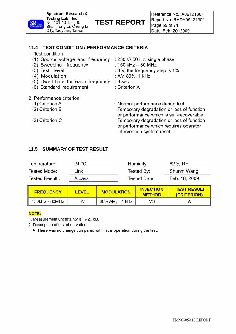
Spectrum Research & Testing Lab., Inc. No. 101-10, Ling 8, Shan-Tong Li, Chung-Li City, Taoyuan, Taiwan
TEST REPORT Reference No.: A09121301 Report No.:RADA09121301 Page:59 of 71 Date: Feb. 20, 2009
FMNG-059.10 REPORT
11.4 TEST CONDITION / PERFORMANCE CRITERIA 1. Test condition
(1) Source voltage and frequency : 230 V/ 50 Hz, single phase (2) Sweeping frequency : 150 kHz – 80 MHz (3) Test level : 3 V, the frequency step is 1% (4) Modulation : AM 80%, 1 kHz (5) Dwell time for each frequency : 3 sec (6) Standard requirement : Criterion A
2. Performance criterion (1) Criterion A : Normal performance during test (2) Criterion B : Temporary degradation or loss of function
or performance which is self-recoverable (3) Criterion C : Temporary degradation or loss of function
or performance which requires operator intervention system reset
11.5 SUMMARY OF TEST RESULT Temperature: 24 °C Humidity: 62 % RH Tested Mode: Link Tested By: Shunm Wang Tested Result : A pass Tested Date: Feb. 18, 2009
NOTE: 1. Measurement uncertainty is +/-2.7dB. 2. Description of test observation:
A: There was no change compared with initial operation during the test.
FREQUENCY LEVEL MODULATION INJECTION METHOD
TEST RESULT (CRITERION)
150kHz - 80MHz 3V 80% AM, 1 kHz M3 A

Spectrum Research & Testing Lab., Inc. No. 101-10, Ling 8, Shan-Tong Li, Chung-Li City, Taoyuan, Taiwan
TEST REPORT Reference No.: A09121301 Report No.:RADA09121301 Page:60 of 71 Date: Feb. 20, 2009
FMNG-059.10 REPORT
12. SURGE TEST
12.1 TEST EQUIPMENT
EQUIPMENT / FACILITIES MANUFACTURER MODEL # /
SERIAL # DUE DATE OF CAL.
& CAL. CENTER
SURGE TEST KeyTek EMC Pro / 0010474
SEP. 2009 ETC
12.2 TEST PROCEDURE
According to EN 301 489-01 V1.8.1:2008, EN 301 489-17 V1.3.2:2008.
12.3 TEST SET-UP
NOTE : 1. The EUT system was put on a wooden table with 0.8m heights above ground reference plane. 2. For the actual test configuration, please refer to the photos of testing.
12.4 DESCRIPTION OF SUPPORT UNIT
Same as section 2.4 of this report.
12.5 EUT OPERATING CONDITION
Same as section 2.5 of this report.
Auxiliary
Equipment SURGE
GENERATOREUT

Spectrum Research & Testing Lab., Inc. No. 101-10, Ling 8, Shan-Tong Li, Chung-Li City, Taoyuan, Taiwan
TEST REPORT Reference No.: A09121301 Report No.:RADA09121301 Page:61 of 71 Date: Feb. 20, 2009
FMNG-059.10 REPORT
12.6 TEST CONDITION / PERFORMANCE CRITERIA
1. Test condition (1) Test level : Common mode : ±0.5kV, ±1kV, ±2kV
Differential mode : ±0.25kV, ±0.5kV, ±1kV (2) Number of Pulse : 5 (3) Phase : 0°, 90°, 180°, 270° (4) Polarity : Positive and Negative polarization (5) Repetition : 60 s (6) Waveform : 1.2/50 µs (open circuit) (7) Standard requirement : Criterion B
2. Performance criterion (1) Criterion A : Normal performance during test (2) Criterion B : Temporary degradation or loss of function
or performance which is self-recoverable (3) Criterion C : Temporary degradation or loss of function
or performance which requires operator intervention system reset
12.7 SUMMARY OF TEST RESULT
Temperature: 24 °C Humidity: 64 % RH Test Mode: Link Tested By: Shunm Wang Atmospheric Air Pressure: 101.2 kPa Tested Date: Feb. 18, 2009 Test Result : Criterion A pass
Phase Mode Coupling Voltage 0° 90° 180° 270°
+/-0.5kV A A A A
+/-1kV A A A A Common L + PE N + PE
+/-2kV A A A A
+/-0.25kV A A A A
+/-0.5kV A A A A Differential L + N
+/-1kV A A A A NOTE: 1. Measurement uncertainty is +/-1.43V 2. Description of test observation:
A: There was no change compared with initial operation during the test. N/A: Not applicable.

Spectrum Research & Testing Lab., Inc. No. 101-10, Ling 8, Shan-Tong Li, Chung-Li City, Taoyuan, Taiwan
TEST REPORT Reference No.: A09121301 Report No.:RADA09121301 Page:62 of 71 Date: Feb. 20, 2009
FMNG-059.10 REPORT
13. VOLTAGE DIPS, INTERRUPTS TEST
13.1 TEST EQUIPMENT
EQUIPMENT / FACILITIES
MANUFACTURER MODEL # / SERIAL #
DUE DATE OF CAL.& CAL. CENTER
INTERFERENCE SIMULATOR
HAEFELY PLINE 1610 / 083-732-05
FEB. 2010 ETC
13.2 TEST PROCEDURE
According to EN 301 489-01 V1.8.1:2008, EN 301 489-17 V1.3.2:2008.
13.3 TEST SET-UP
NOTE : 1. The EUT system was put on a wooden table with 0.8m heights above ground. 2. For the actual test configuration, please refer to the photos of testing.
13.4 DESCRIPTION OF SUPPORT UNIT
Same as section 2.4 of this report.
13.5 EUT OPERATING CONDITION
Same as section 2.5 of this report.
Frequency
Converter
Interference
Simulator EUT Auxiliary Equipment
Power cable

Spectrum Research & Testing Lab., Inc. No. 101-10, Ling 8, Shan-Tong Li, Chung-Li City, Taoyuan, Taiwan
TEST REPORT Reference No.: A09121301 Report No.:RADA09121301 Page:63 of 71 Date: Feb. 20, 2009
FMNG-059.10 REPORT
13.6 TEST CONDITION / PERFORMANCE CRITERIA
1. Test condition (1) Source voltage and frequency : 100V/50Hz, 240V/50Hz, single phase (2) Test level : Dip depth 30%, 25 period
Interrupt 100%, 250 period (3) Phase : 0°, 180° (4) Test duration : 2min each phase (5) Time between test : 10 sec (6) Standard requirement : Dip 30% : Criterion B;
Interrupt 100%: Criterion C
2. Performance criterion (1) Criterion A : Normal performance during test (2) Criterion B : Temporary degradation or loss of function
or performance which is self-recoverable. (3) Criterion C : Temporary degradation or loss of function
or performance which requires operator intervention system reset.
13.7 SUMMARY OF TEST RESULT
Temperature: 23 °C Humidity: 59 % RH Test Mode: Link Tested By: Shunm Wang Test Result: Pass Tested Date: Dec. 08, 2008
NOTE: 1. The power voltage range: 100 V to 240V range 140V is 140% of the lowest voltage or the power voltage is 230 V.
2. Description of test observation: A: There was no change compared with initial operation during the test. C: EUT requires operator intervention system reset.
AC POWER
DIP DEPTH INTERVAL DIP TIME TEST TIME PHASE
TEST RESULT
(Criterion) 0° A 30% 10 sec 25 period 500 min
180° A 0° C
100V/50Hz 100%
(interrupt) 10 sec 250 period 5000 min 180° C
AC POWER
DIP DEPTH INTERVAL DIP TIME TEST TIME PHASE
TEST RESULT
(Criterion) 0° A 30% 10 sec 25 period 500 min
180° A 0° C
240V/50Hz 100%
(interrupt) 10 sec 250 period 5000 min 180° C

Spectrum Research & Testing Lab., Inc. No. 101-10, Ling 8, Shan-Tong Li, Chung-Li City, Taoyuan, Taiwan
TEST REPORT Reference No.: A09121301 Report No.:RADA09121301 Page:64 of 71 Date: Feb. 20, 2009
FMNG-059.10 REPORT
14. PHOTOS OF TESTING - Conducted emission test

Spectrum Research & Testing Lab., Inc. No. 101-10, Ling 8, Shan-Tong Li, Chung-Li City, Taoyuan, Taiwan
TEST REPORT Reference No.: A09121301 Report No.:RADA09121301 Page:65 of 71 Date: Feb. 20, 2009
FMNG-059.10 REPORT
- Radiated emission test (below 1GHz)

Spectrum Research & Testing Lab., Inc. No. 101-10, Ling 8, Shan-Tong Li, Chung-Li City, Taoyuan, Taiwan
TEST REPORT Reference No.: A09121301 Report No.:RADA09121301 Page:66 of 71 Date: Feb. 20, 2009
FMNG-059.10 REPORT
- Radiated emission test (above 1GHz)

Spectrum Research & Testing Lab., Inc. No. 101-10, Ling 8, Shan-Tong Li, Chung-Li City, Taoyuan, Taiwan
TEST REPORT Reference No.: A09121301 Report No.:RADA09121301 Page:67 of 71 Date: Feb. 20, 2009
FMNG-059.10 REPORT
- Harmonics and Voltage fluctuations Flicker test
- Electrostatic discharge immunity test

Spectrum Research & Testing Lab., Inc. No. 101-10, Ling 8, Shan-Tong Li, Chung-Li City, Taoyuan, Taiwan
TEST REPORT Reference No.: A09121301 Report No.:RADA09121301 Page:68 of 71 Date: Feb. 20, 2009
FMNG-059.10 REPORT
- Electrical fast transient / burst immunity test
-Surge test (Power Line)

Spectrum Research & Testing Lab., Inc. No. 101-10, Ling 8, Shan-Tong Li, Chung-Li City, Taoyuan, Taiwan
TEST REPORT Reference No.: A09121301 Report No.:RADA09121301 Page:69 of 71 Date: Feb. 20, 2009
FMNG-059.10 REPORT
- Radiated immunity test

Spectrum Research & Testing Lab., Inc. No. 101-10, Ling 8, Shan-Tong Li, Chung-Li City, Taoyuan, Taiwan
TEST REPORT Reference No.: A09121301 Report No.:RADA09121301 Page:70 of 71 Date: Feb. 20, 2009
FMNG-059.10 REPORT
- Inducted RF fields (conducted susceptibility) test
- Voltage dips, interrupts, variations test

Spectrum Research & Testing Lab., Inc. No. 101-10, Ling 8, Shan-Tong Li, Chung-Li City, Taoyuan, Taiwan
TEST REPORT Reference No.: A09121301 Report No.:RADA09121301 Page:71 of 71 Date: Feb. 20, 2009
FMNG-059.10 REPORT
15. TERMS OF ABRIVATION AV. Average detection AZ(°) Turn table azimuth Correct. Correction EL(m) Antenna height (meter) EUT Equipment Under Test Horiz. Horizontal direction LISN Line Impedance Stabilization Network NSA Normalized Site Attenuation Q.P. Quasi-peak detection SRT Lab Spectrum Research & Testing Laboratory, Inc. Vert. Vertical direction