spectrum control, inc. - bl831.als.lbl.govgmeigs/pdf/smart_switch_jr.pdf · with this manual and...
TRANSCRIPT

Spectrum Control, Inc. Installation and Operation Manual
27-0027-0055-00
PPIR/ECN: -CPD Rev. 07 SCI P/N: 7608A series Date: 04/28/04 Page 1 of 67
Spectrum Control, Inc.
7608A Series Power Distribution Units (PDU’s)
Installation and Operation Manual

Spectrum Control, Inc. Installation and Operation Manual
27-0027-0055-00
PPIR/ECN: -CPD Rev. 07 SCI P/N: 7608A series Date: 04/28/04 Page 2 of 67
Table of Contents
Title Page # 1.0 Introduction ................................................................................. 4
2.0 Safety Information ....................................................................... 5 3.0 Technical Specifications.............................................................. 6 - 7 4.0 Connections and Installation information..................................... 8 - 15 5.0 Operational Commands .............................................................. 16 - 21 6.0 Smart Start Jr Windows Configuration Utility............................... 22 - 35 7.0 LAN Module and Communications.............................................. 36 - 60 8.0 Maintenance and Replacement Parts ......................................... 61 9.0 Warranty...................................................................................... 61 List of Figures Figure 4.1 Back Panel................................................................... 11 Figure 4.2 Hook-up to remote PC or Laptop Computer ................ 12 Figure 4.3 Hook-up to remote PDA............................................... 13 Figure 4.4 LED Descriptions ......................................................... 15 Figure 6.1 Control Software Setup Screen ................................... 23 Figure 6.2 Select Installation Folder ............................................. 24 Figure 6.3 Software Installed Successfully ................................... 25 Figure 6.4 Connect to a PDU........................................................ 26 Figure 6.5 Select PDU Type ......................................................... 27 Figure 6.6 Configure Communication Settings ............................. 28 Figure 6.7 Control and Monitoring Windows ................................. 29 Figure 6.8 Example of All Windows .............................................. 30 Figure 6.9 Sequence and Delay Settings...................................... 31 Figure 6.10 Communication Settings.............................................. 32 Figure 6.11 Alarm Settings ............................................................. 33 Figure 6.12 Auxiliary Settings ......................................................... 34 Figure 7.1 RJ45 Ethernet Connector ........................................... 36 Figure 7.2 Configuration Menu Using Telnet ................................ 40 Figure 7.3 Server Configuration.................................................... 41 Figure 7.4 Serial Channel 1 Configuration .................................... 43 Figure 7.5 Login Failure Threshold Setpoint ................................. 44 Figure 7.6 Communication Failure Threshold Setpoint ................. 45 Figure 7.7 Web Interface Monitor Screen ..................................... 47 Figure 7.8 Web Interface Login Screen ........................................ 48 Figure 7.9 Unit Setup Using Web Interface................................... 49 Figure 7.10 Web Interface Alert Setup............................................ 50

Spectrum Control, Inc. Installation and Operation Manual
27-0027-0055-00
PPIR/ECN: -CPD Rev. 07 SCI P/N: 7608A series Date: 04/28/04 Page 3 of 67
Figure 7.11 Web Interface External Circuit Setup Screen............... 52 Figure 7.12 Web Interface User Setup Screen ............................... 53 Figure 7.13 Web Interface Outlet Control ....................................... 54 Figure 7.14 Web Interface About Screen........................................ 55 Figure 7.15 Web Interface Device Organizer.................................. 58 Figure 7.16 Device Organizer Edit Menu........................................ 59 Figure 7.17 Device Organizer Node Dialog .................................... 60 Appendix A Network Notation and IP Addressing Basics …………..64-67

Spectrum Control, Inc. Installation and Operation Manual
27-0027-0055-00
PPIR/ECN: -CPD Rev. 07 SCI P/N: 7608A series Date: 04/28/04 Page 4 of 67
1.0 Introduction
The Spectrum Control Smart Start Jr. is a multifunctional AC power
distribution unit sophisticatedly designed to control up to eight AC loads and monitor vital parameters. The PDU has two main configurations. The first configuration has a single input and eight outputs. The second configuration has two independent inputs and each of the inputs has four outputs associated with it. There are various current ratings available. Each input has a circuit breaker to protect the PDU and associated loads. A programmable software current limit is also available for added protection. The communication and control circuitry is protected by internal fuses. The unit can still communicate when the circuit breaker is in the tripped position.
The Smart Start Jr. is capable of monitoring line voltage and total
load current as well as line frequency and external temperature. Operation/control is accomplished either manually using controls on the front panel of the unit or by several communication schemes using a remote computing device such as a laptop computer, desktop computer, palm pilot, etc.
This product complies with FCC, CE, TUV, UL60950 and IEC950
requirements.

Spectrum Control, Inc. Installation and Operation Manual
27-0027-0055-00
PPIR/ECN: -CPD Rev. 07 SCI P/N: 7608A series Date: 04/28/04 Page 5 of 67
2.0 Safety Information
This installation and operation manual contains information about the Power Distribution Unit and basic installation instructions. The person installing or integrating the PDU into an electronic system must be supplied with this manual and they must read it to become familiar with the installation precautions. Spectrum Control, Inc cannot be held liable for any damage to persons or property if the safety information in the installation and operation manual is not followed.
If the safety information is not observed, personnel could be put at
risk. Only authorized personnel who have been properly trained may operate the device. There are no user serviceable parts inside and any modifications made to the unit by any organization or persons other than the factory are not permitted.
The general regulations governing the use of electricity in the country
in which the device or integrated system is installed must be observed.

Spectrum Control, Inc. Installation and Operation Manual
27-0027-0055-00
PPIR/ECN: -CPD Rev. 07 SCI P/N: 7608A series Date: 04/28/04 Page 6 of 67
3.0 Technical Specifications
Input
• Power Entry Connector: IEC 320/C14 • Nominal input voltage:
120VAC ±10% for Models with “12” in the 9th and 10th digit of the part number. 230 VAC ± 10% for Models with “24” in the 9th and 10th digit of the part number.
• Input frequency: 47 – 63 Hz • Input current:
15A, 20A or 30A* maximum per input (120VAC models) 7.5A, 16A or 30A* maximum per input (230VAC models)
Outputs • Outlet Connectors: (8) Nema 5-15R, (8) Nema 5-20R or
(8) IEC 320/C13 • Load Current:
15A or 20A maximum per outlet group (120VAC models) 7.5A or 10A maximum per outlet group (230VAC models)
Maximum load current of all receptacles combined within an outlet group, consult factory for other current ratings.
Communication • Telnet or WEB Browser using optional LAN module • RS-232: front panel DB-9F or DB-9M connector • RS-485/RS-422: rear panel RJ-11 connector
(Caution: Do not connect this jack to a telephone network.)
*Note: Single input configuration only.

Spectrum Control, Inc. Installation and Operation Manual
27-0027-0055-00
PPIR/ECN: -CPD Rev. 07 SCI P/N: 7608A series Date: 04/28/04 Page 7 of 67
Auxiliary Connections • Two input connections to generate messages. Make or break
contact between two points on connector. 28 to 16 AWG solid or stranded jumper wire.
• Two Full sets of dry contacts (c, no, nc) rated 2A max, 250VAC max. (60 watts max)
• Optional E-STOP connection. Make or break contact between two points on connector. 28 to 16 AWG solid or stranded jumper wire.
• Optional temperature sensor connection.
Environmental
• Operating temperature: 0-45°C (32-113°F) • Operating humidity: 0-95% (non condensing) • Operating elevation: 0-10,000 ft (0-3000m)
Physical
• Unit height: 1U, 1.75 inches (4.44cm) • Unit width: 17.25 inches (43.8cm) • Unit depth: 8.25 inches (20.9cm) • Weight: approximately 8 lbs. (3.7kg) • 19” Rack mountable or tabletop • Finish: Black powder coat

Spectrum Control, Inc. Installation and Operation Manual
27-0027-0055-00
PPIR/ECN: -CPD Rev. 07 SCI P/N: 7608A series Date: 04/28/04 Page 8 of 67
4.0 Connections and Installation Information
4.1 Operating Environment
• Locate PDU in dry area on a bench, desktop or shelf. • Rack Mount in equipment rack using mounting brackets. PDU
may be flush with front of rack or center mounted. • Elevated Operating Ambient—If installed in a closed or multi-unit
rack assembly, the operating ambient temperature of the rack environment may be greater than room ambient. Therefore, consideration should be given to installing the equipment in an environment compatible with the maximum ratings of the product.
• Installation of the equipment should be such that the amount of airflow required for safe operation of the equipment is not compromised.
• Mounting of the equipment in the rack should be such that a hazardous condition is not achieved due to uneven mechanical loading.
• Consideration should be given to the connection of the equipment to the supply circuit and the effect that overloading of the circuits might have on over current protection and supply wiring. Appropriate consideration of equipment nameplate ratings should be used when addressing this concern.
• Reliable earthing of equipment should be maintained. Particular attention should be given to supply connections other than direct connections to the branch circuit (e.g. use of power strips). Consult the local electrical code for additional information.

Spectrum Control, Inc. Installation and Operation Manual
27-0027-0055-00
PPIR/ECN: -CPD Rev. 07 SCI P/N: 7608A series Date: 04/28/04 Page 9 of 67
4.2 Electrical Connections
4.2.1 For 120 VAC products • Depress rocker handle of all circuit breakers to “off” position,
Figure 4.2. • Connect a 3-conductor AC line cord, Figure 4.1 Item A, to the
power entry module(s) at the rear panel, Figure 4.1 Item B. Cord must be rated at least or more than the input current rating of the PDU. Power source must also be rated for appropriately and have a ground.
• Connect equipment to AC outputs, Figure 4.1 Item C. Continuous current draw for all connected units must not exceed the current rating per output group.
CAUTION: • Power source for PDU must be properly grounded. • Cord for PDU must be rated at least or more than the rating of
the PDU. • Total current for all connected units must not exceed the
current rating per input.
4.2.2 For 230 VAC products • Depress rocker handle of all circuit breakers to “off” position,
Figure 4.2. • Connect a 3-conductor AC line cord, Figure 4.1 Item A, to the
power entry module(s) at the rear panel, Figure 4.1 Item B. Cord must be rated at least or more than the rating of the PDU. Power source must also be rated for 7.5A and have ground.
• Connect equipment to AC outputs, Figure 4.1 Item A. Continuous current draw for all connected units must not exceed the current rating per output group.
CAUTION: • Power source for PDU must be properly grounded. • Cord for PDU must be rated at least or more than the rating of
the PUD. • Total current for all connected units must not exceed the
current rating per input.

Spectrum Control, Inc. Installation and Operation Manual
27-0027-0055-00
PPIR/ECN: -CPD Rev. 07 SCI P/N: 7608A series Date: 04/28/04 Page 10 of 67
4.3 Communication Hook Up
• For LAN communications plug into the front RJ-45 jack Figure 4.2 Item G. When connecting to a 10/100 Base-T ethernet LAN hub or router use a straight through LAN cable. Use a crossover cable if connecting the PDU directly to a PC LAN port.
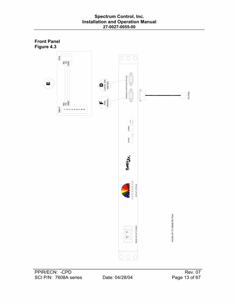
• For RS-232 to PC or laptop computer use a straight through serial cable to the RS-232 (DB-9S) connector on front panel, Figure 4.2D. Connector pin-outs are shown in Figure 4.2 Item E. Palm PDA’s connect directly to the DB-9P connector on the front panel, Figure 4.2F. A null modem is not required.
• RS-485/RS-422 interfacing is available at rear panel 6 position modular jack (RJ11), Figure 4.1 Item D. Caution: Do not connect this jack to a telephone network.
• Consult Factory for additional Assistance with this communication Scheme.
CAUTION:
Do not connect any cable to rear RJ11 connector unless the internal configuration of this connector is known. Damage to the Smart Start Junior or connecting computing device may occur.
4.4 Auxiliary Input and Output Connections
• Temperature probe input, isolated inputs and programmable isolated relay outputs are connected to header on rear of the unit. Figure 4.1 Item E, shows the location and designation of the connections. A pluggable mating connector with screw clamp type terminals is supplied with the unit. Pin-outs are shown in Figure 4.1 Item F.
• The temperature probe should be of a type using a TMP35, LM35 or equivalent based an a two wire current based circuit with a 881 ohm scaling resistor.
• See commands for direct relay control AFFCA, and AFFCB in Section 5 for information on setting up the programmable relays.
• See commands AFFW1 and AFFW2 for using the input signals. These signals are generated when two points on the auxiliary connector are connected or disconnected from signal ground.

Spectrum Control, Inc. Installation and Operation Manual
27-0027-0055-00
PPIR/ECN: -CPD Rev. 07 SCI P/N: 7608A series Date: 04/28/04 Page 11 of 67
Back Panel Figure 4.1
12
34
56
RS
-485
/ R
S-42
2R
J11
2 64 53
RJ1
1 12 63 541
RJ1
1
T/R
(-)
910
1112
1314
1516
26
87
54
31
AA
C P
OW
ER
SU
PPLY
TO E
QU
IPM
EN
T
TO I/
OC
ON
TAC
T O
UTP
UTS
CO
NTA
CT
INP
UTS
TEM
PER
ATU
RE
SEN
SO
R
F
RJ1
1D16
PIN
PH
OEN
IX
EA
CIN
PU
T
BFI
GU
RE
4.1
CO
UTP
UT
AC
1 91
87
65
43
21
120
VAC
INP
UT
AU
XIL
IAR
Y
OPT
ION
ALE
XTE
RN
ALC
OM
M
TEM
P Vc
TEM
P C
OM
MO
NTE
MP
IN
TYP
ICAL
INTE
RFA
CE
T/R
(+)
FOR
MAS
TER
/ SL
AVE
CO
NFI
GU
RA
TIO
NC
ON
TAC
T TH
E F
ACTO
RY
{CONTR
OL
AFFL
B
{
CO
NTR
OL
AFF
LB

Spectrum Control, Inc. Installation and Operation Manual
27-0027-0055-00
PPIR/ECN: -CPD Rev. 07 SCI P/N: 7608A series Date: 04/28/04 Page 12 of 67
Front Panel Figure 4.2
LOA
D S
TA
TUS
HO
OK
-UP
TO
RE
MO
TE P
C O
R L
AP
TOP
CO
MP
UTE
R
5
OFF O
ON I
RE
AR
OU
TLE
T P
OW
ER
31
24
BR
EA
KE
RO
FF /
ON
LOC
AL
TO P
C /
LAP
TOP
smart
ST
AR
TSTA
RT
P.B
UTT
ON
RE
AD
Y
SP
EC
TRU
M C
ONT
ROL,
INC.
5
OU
TLE
T S
TA
TUS
86
7
12
34
67
8
Jr.
CO
MM
.S
TAR
T
RE
MO
TE
RD
Y
REM
OTE
LOC
AL
CH
2D
IA
CO
MM
.S
WIT
CH
LNK
CH
1LANG
DB
9 M
1 2 3 4 5 6 7 8 9
LAN
DC
ED
TE
CO
NS
OLE
PO
RTS
(EIA
RS
-232
)
PD
AR
S23
2C
FD
CO
MP
UTE
RR
S23
2C
TO P
C
GN
D
TO P
DU
GN
D
TDRD
TDRD
E
DB
9 F
1 2 3 4 5 6 7 8 9
Spectrum Control, Inc. Installation and Operation Manual
27-0027-0055-00
PPIR/ECN: -CPD Rev. 07 SCI P/N: 7608A series Date: 04/28/04 Page 13 of 67
Front Panel Figure 4.3
6 87
DB
9 F
TD2
GN
D
4 531
PD
A
TDG
ND
RD
RD
TO P
DA
E
9
STA
RT
CO
MM
.
RD
YLO
CAL
RE
MO
TE
CO
NSO
LE P
OR
TS (E
IA R
S-2
32)
OU
TLE
T ST
A TU
S
15
42
38
67
STA
RT
smart Jr .
RE
AR
OU
TLE
T P
OW
ER
OFF
ON
OI
LOC
AL
EIA
RS2
32C
D
HO
OK
-UP
TO
REM
OTE
PD
A
FR
S232
CPD
A

Spectrum Control, Inc. Installation and Operation Manual
27-0027-0055-00
PPIR/ECN: -CPD Rev. 07 SCI P/N: 7608A series Date: 04/28/04 Page 14 of 67
4.5 LED status guide
LED Status Description
Off Voltage is turned off to the outlet. Outlet Status
(Green LED) On Voltage is applied to the outlet
Off No power applied to the unit, rear jumper removed (EPO), or unit inoperable.
Green Operating normally
RDY (Ready)
Blinking Normal communications with LAN module or RS-232 ports.
LOCAL On In local mode. Start button on front panel enabled.
REMOTE On In remote mode. External communications enabled.
Off No power applied to the unit, or LAN module inoperable.
Green Normal operation of LAN module once booted up.
CH1 (Upper left)
Green blinking Normal operation of LAN module when communicating.
Off No link or connection to a network. LNK (Upper right)
Green Network link valid.
Off Unit operating normally DIA (Lower left)
Red or blinking Diagnostic failure. Contact factory for further information.
Off Operating normally CH2 (Lower right)
Yellow or Blinking CH2 active, consult with factory for further information.
2
1
5
6
7
8
3
4

Spectrum Control, Inc. Installation and Operation Manual
27-0027-0055-00
PPIR/ECN: -CPD Rev. 07 SCI P/N: 7608A series Date: 04/28/04 Page 15 of 67
Figure 4.4
OUTLET STATUSDTEDCE
START COMM.
RDY LOCAL
REMOTE
REAR OUTLET POWER
CONSOLE PORTS (EIA RS-232)
1 542 3 86 7
SPECTRUM CONTROL, INC.
CH1 LNK
DIA CH2
LANJr.smartSTART
OFFO
ONI
2
5
1 3
4 6
7 8

Spectrum Control, Inc. Installation and Operation Manual
27-0027-0055-00
PPIR/ECN: -CPD Rev. 07 SCI P/N: 7608A series Date: 04/28/04 Page 16 of 67
5.0 Operational Commands
The PDU is shipped with a factory default setting of address FF. All basic commands would begin with “AFF”. If the unit address is changed to another hex number the command structure would also change. All control and configuration of the SSJR settings can be changed using the command set below. LAN module configuration can only be performed through the LAN connection. Please see section 7.0 for LAN module configuration.
The basic commands are valid only when the SSJR is in the remote
mode and the user is communicating using RS-232, RS422/485 or Telnet. If a external software program is used to issue commands a delay of 10 milliseconds should be used between characters and 40 milliseconds between commands being sent should be used. If the user is typing the commands below no delays are necessary as the communication scheme can keep up with the speed of the human interface.
SSJR COMMANDS The following commands are based on factory default settings. All commands must be followed by a carriage return. For 1X8 units use the “A” commands, for 2X4 units use the “A” and “B” commands.
Command Explanation Response BAUD RATE AFFB Returns current baud rate setting UFFB1 AFFB0 Set baudrate to 4,800 bps UFFB0 AFFB1 Set baudrate to 9,600 bps UFFB1 AFFB2 Set baudrate to 19,200 bps UFFB2 AFFB3 Set baudrate to 38,400 bps UFFB3
If a LAN module is present do not use this command. Use the LAN module configuration menu on telnet port 9999 menu choice 1 “Channel 1 configuration”
EXTERNAL CONTACTS (Bot row pins 6, 7, 8) When the PDU is
powered on all external contact relays are turn on. AFFCA Returns the setting of the external contact configuration. UFFCA FF
AFFCA FF Sets external contacts to monitor undervoltage condition on channel A (see AFFUA command for setpoint details) UFFCA FF
AFFCA DD Sets external contacts to monitor overcurrent condition on channel A (see AFFLA command for setpoint details) UFFCA DD
AFFCA CC Sets external contacts to monitor overtemperature condition (see AFFK command for setpoint details) UFFCA CC

Spectrum Control, Inc. Installation and Operation Manual
27-0027-0055-00
PPIR/ECN: -CPD Rev. 07 SCI P/N: 7608A series Date: 04/28/04 Page 17 of 67
AFFCA 00 Sets external contacts to the OFF position. UFFCA 00 AFFCA 01 Sets external contacts to the ON position. UFFCA 01
EXTERNAL CONTACTS (Top row pins 1, 2, 3) When the PDU is powered on the external contact relays are turned
on. AFFCB Returns the setting of the external contact configuration. UFFCB FF
AFFCB FF Sets external contacts to monitor undervoltage condition on channel A (see AFFUB command for setpoint details) UFFCB FF
AFFCB DD Sets external contacts to monitor overcurrent condition on channel A (see AFFLB command for setpoint details) UFFCB DD
AFFCB CC Sets external contacts to monitor overtemperature condition (see AFF command for setpoint details) UFFCB CC
AFFCB 00 Sets external contacts to the OFF position. UFFCB 00 AFFCB 01 Sets external contacts to the ON position. UFFCB 01 SEQUENCE DELAY
AFFD Returns the current time delay between each outlet turning on or off in tenths of seconds . UFFD010
AFFD050 Changes the time delay to 5 seconds between each outlet turning on or off. Valid settings are from 001 to 300. UFFD050
TURN OFF ALL OUTLETS AFFE Turns all the outputs off at the same time UFFE LINE FREQUENCY AFFFA Returns the line frequency for channel “A” UFFFA060.0 HZ AFFFB Returns the line frequency for channel “B” UFFFB060.0 HZ TOAL LOAD CURRENT AFFIA Returns the total load current for channel “A” UFFIA12.13 Amps AFFIB Returns the total load current for channel “B” UFFIB10.11 Amps POWER ON CURRENT LIMIT
AFFLA
Returns the power on current limit setting for channel “A”. Once the load current equals or exceeds this value the remaining outlets will not be energized. Valid range is 2.0 to 25.5 amps (14 to FF hex) UFFLA 96
AFFLA 66
Changes the power on current limit setting for channel “A” to 12 amps. Value to be scaled by 10.0 and then converted to a hex number. 12.0 amps desired trip X 10.0 = 120 then converted to a hex number = 78 UFFLA 78
AFFLB
Returns the power on current limit setting for channel “B”. Once the load current equals or exceeds this value the remaining outlets will not be energized. Valid range is 2.0 to 25.5 amps (10 to FF hex) UFFLB 96
AFFLB 32
Changes the power on current limit setting for channel “B” to 5.0 amps. Value to be scaled by 10.0 and then converted to a hex number. 5.0 amps desired trip X 10.0 = 50 then converted to a UFFLA 32

Spectrum Control, Inc. Installation and Operation Manual
27-0027-0055-00
PPIR/ECN: -CPD Rev. 07 SCI P/N: 7608A series Date: 04/28/04 Page 18 of 67
hex number = 32
If the current limit is exceeded during sequencing the unit will respond with IOVER and the outlet numbers that were not turned on. IOVER8
EPO COMMUNICATION SETTINGS AFFH Returns the current EPO communication setting. UFFH0
AFFH0
Configures the EPO setting so that when the EPO communication setting is 0, no response is issued and the ready light on the front panel is off during the EPO condition UFFH0
AFFH1
Configures the EPO setting so that when the EPO communication setting is 1, the UFFEPO response is issued for every command received during the EPO condition UFFH1 or UFFEPO
AFFH2 Configures the EPO setting so that user intervention is required before the unit will re-sequence back on. UFFH2
REMOTE TEMPERATURE SETTINGS AFFK Returns the current over temperature setting. UFFK FF
AFFK 37
Changes the value of the over temperature setpoint to 37 Hex. 37 = 55 degrees C Valid range from 00 to FF hex. FF = off/sensor not connected. UFFK 37
MASTER/SLAVE CONFIGURATION AFFM Returns the master/slave setting UFFM0 AFFM0 Changes the master/slave setting to a stand alone unit UFFM0 AFFM1 Changes the master/slave setting to a master UFFM1 AFFM2 Changes the master/slave setting to a slave UFFM2 PDU ADDRESS AFFN Returns the current address of the PDU UFFNFF
AFFNAA Changes the address of the PDU to AA. Valid range from 00 to FF hex. UFFNAA
TURN ON OUTLETS
AFFP Sequences outlets 1 through 8 on in the order of the programmed start up sequence. UFFP
AFFPA Sequences outlets 1 through 4 on in the order of the programmed start up sequence. UFFPA
AFFPB Sequences outlets 5 through 8 on in the order of the programmed start up sequence. UFFPB
SEQUENCE OFF OUTLETS
AFFQ Sequences the outlets off in the reverse order of the start up sequence. UFFQ

Spectrum Control, Inc. Installation and Operation Manual
27-0027-0055-00
PPIR/ECN: -CPD Rev. 07 SCI P/N: 7608A series Date: 04/28/04 Page 19 of 67
AFFQA Sequences outlets 1 through 4 off in the reverse order of the start up sequence. UFFQA
AFFQB Sequences outlets 5 through 8 off in the reverse order of the start up sequence. UFFQB
DIRECT OUTLET ACCESS AFFr01 Returns the status of outlet #1 UFFr01 1 AFFr01 0 Turns outlet #1 off UFFr01 0 AFFr01 1 Turns outlet #1 on UFFr01 1 AFFr02 Returns the status of outlet #2 UFFr02 1 AFFr02 0 Turns outlet #2 off UFFr02 0 AFFr02 1 Turns outlet #2 on UFFr02 1 AFFr03 Returns the status of outlet #3 UFFr03 1 AFFr03 0 Turns outlet #3 off UFFr03 0 AFFr03 1 Turns outlet #3 on UFFr03 1 AFFr04 Returns the status of outlet #4 UFFr04 1 AFFr04 0 Turns outlet #4 off UFFr04 0 AFFr04 1 Turns outlet #4 on UFFr04 1 AFFr05 Returns the status of outlet #5 UFFr05 1 AFFr05 0 Turns outlet #5 off UFFr05 0 AFFr05 1 Turns outlet #5 on UFFr05 1 AFFr06 Returns the status of outlet #6 UFFr06 1 AFFr06 0 Turns outlet #6 off UFFr06 0 AFFr06 1 Turns outlet #6 on UFFr06 1 AFFr07 Returns the status of outlet #7 UFFr07 1 AFFr07 0 Turns outlet #7 off UFFr07 0 AFFr07 1 Turns outlet #7 on UFFr07 1 AFFr08 Returns the status of outlet #8 UFFr08 1 AFFr08 0 Turns outlet #8 off UFFr08 0 AFFr08 1 Turns outlet #8 on UFFr08 1 OUTLET STATUS
AFFS
Returns the status of the unit. The status is displayed in HEX format. The fifth digit represents outlets 8 through 5 MSB to LSB, and the sixth digit represents outlets 4 through 1 MSB to LSB. If the outlet is on the bit representing that outlet is turned on (0 = no, 1 = yes). The seventh digit represents remote ® or local (L) mode. UFFSFFR
AFFS00
Turns all relays off simultaneously. The last two digits of the command are in hex format and will control all 8 relays. This command is useful to control multiple relays at the same time. Any two digit hex number conbination can be used between 00 to FF. UFFS00R

Spectrum Control, Inc. Installation and Operation Manual
27-0027-0055-00
PPIR/ECN: -CPD Rev. 07 SCI P/N: 7608A series Date: 04/28/04 Page 20 of 67
TEMPERATURE MEASUREMENT
AFFt Returns the temperature reading from the optional external temperature probe. (0 to 100 C) UFFt 000.0 C Temp

Spectrum Control, Inc. Installation and Operation Manual
27-0027-0055-00
PPIR/ECN: -CPD Rev. 07 SCI P/N: 7608A series Date: 04/28/04 Page 21 of 67
OUTLET SEQUENCE CONFIGURATION AFFT01 Returns the value of the first outlet to turn on UFFT01 AFFT02 Returns the value of the second outlet to turn on UFFT02 AFFT03 Returns the value of the third outlet to turn on UFFT03 AFFT04 Returns the value of the fourth outlet to turn on UFFT04 AFFT05 Returns the value of the fifth outlet to turn on UFFT05 AFFT06 Returns the value of the sixth outlet to turn on UFFT06 AFFT07 Returns the value of the seventh outlet to turn on UFFT07 AFFT08 Returns the value of the eighth outlet to turn on UFFT08
AFFT01 08 Sets outlet #8 to turn on first in the programmed sequence. UFFT01 08
AFFT02 07 Sets outlet #7 to turn on second in the programmed sequence. UFFT02 07
AFFT03 06 Sets outlet #6 to turn on third in the programmed sequence. UFFT03 06
AFFT04 05 Sets outlet #5 to turn on fourth in the programmed sequence. UFFT04 05
AFFT05 04 Sets outlet #4 to turn on fifth in the programmed sequence. UFFT05 04
AFFT06 03 Sets outlet #3 to turn on sixth in the programmed sequence. UFFT06 03
AFFT07 02 Sets outlet #2 to turn on seventh in the programmed sequence. UFFT07 02
AFFT08 01 Sets outlet #1 to turn on eighth in the programmed sequence. UFFT08 01
UNDERVOLTAGE SETPOINTS
AFFUA Returns the current value of the “A” channel undervoltage dropout setpoint in Hex format. 5A = 90 VAC UFFUA 5A
AFFUA D2
Changes the value of the “A” channel undervoltage dropout setpoint to D2 Hex. D2 = 210VAC Valid range from 00 to FF hex. UFFUA D2
AFFUB Returns the current value of the “B” channel undervoltage dropout setpoint in Hex format. 5A = 90 VAC UFFUB 5A
AFFUB D2
Changes the value of the “B” channel undervoltage dropout setpoint to D2 Hex. D2 = 210VAC Valid range from 00 to FF hex. UFFUB D2
SOFTWARE VERSION AFFv Returns the microprocessor software version UFFvSSJR 1X8 v3.4 LINE VOLTAGE MEASUREMENT AFFVA Returns the input voltage level for channel “A” UFFVA123.5 Volts AFFVB Returns the input voltage level for channel “B” UFFVB118.5 Volts

Spectrum Control, Inc. Installation and Operation Manual
27-0027-0055-00
PPIR/ECN: -CPD Rev. 07 SCI P/N: 7608A series Date: 04/28/04 Page 22 of 67
REMOTE MESSAGE/WORD FUNCTION
AFFW1 Returns the value of the #1 remote message.(FF not active, 00 active) UFFW1 FF
AFFW1 00 Activates the #1 remote message function. UFFW1 00 N/A Remote message indicator word UFFW1 01
AFFW2 Returns the value of the #2 remote message.(FF not active, 00 active) UFFW2 FF
AFFW2 00 Activates the #2 remote message function. UFFW2 00 N/A Remote message indicator word UFFW2 01 RESTORE FACTORY DEFAULTS AFFZ Changes all settings back to factory default UFFZ Notes:
1. All initiated messages are prefixed with Axx, where “A” is an ASCII upper case character (Hex code = 41). “xx” is a two-character hex code address in the range 00 to FF representing an ASCII code address range from 0 to 128. Hex address 00 is the general broadcast address to all devices.
2. All commands & responses end with an ASCII carriage return character (Hex code = 0D)
3. Any command can be aborted prior to sending a carriage return by sending a Cancel (Hex = 18), or Escape (Hex = 1B) character. The PDU will discard any previous characters, and immediately look for a valid address header.
4. PDU’s that receive messages with a correct address, but fail to recognize the specific command parameters, or have illegal command parameters, will return a response with the command that was entered followed by a “?”
5. Unit will respond to a broadcast command with address “00” only if the “Start” button is depressed while the PDU is in the remote operation mode.
6. Lowest measured temperature is 0oC. There is no indication of minus temperature.
Spectrum Control, Inc. Installation and Operation Manual
27-0027-0055-00
PPIR/ECN: -CPD Rev. 07 SCI P/N: 7608A series Date: 04/28/04 Page 23 of 67
6.0 Windows Configuration and Control Utility
The PDU management utility is designed to provide a graphical user interface to operate and control the all PDU’s manufactured by Spectrum Control. It provides a single program to interface to many different PDU’s.
6.1 SYSTEM REQUIREMENTS
• 32 bit Windows operating systems, including: • Windows 95, Windows 98 and later or • Windows NT 4.0 with service pack 3, Windows 2000 and later. • Internet Explorer 4.0 or later. • Video resolution of 800 x 600 in high color mode. • 64 MB or RAM. • One open COM port for RS232 communication. • Windows Mouse or compatible pointing device. Note: Windows 95 and Windows NT are trademarks of Microsoft Corporation.
6.2 PROGRAM SETUP
Follow the instructions included with the media package. The installation program will install the program and create system shortcuts in the system start menu.
To remove the program, follow the instructions from your particular operating system. These directions normally point the user to the Control Panel Add/Remove programs wizard.
NOTE: Some installations may require a reboot in order to update runtime files or controls before final installation.
Load the CD into the computer which will control the PDU
using a serial interface. Lauch the program by double clicking on the SETUP.EXE icon. The following window will be displayed.

Spectrum Control, Inc. Installation and Operation Manual
27-0027-0055-00
PPIR/ECN: -CPD Rev. 07 SCI P/N: 7608A series Date: 04/28/04 Page 24 of 67
Figure 6.1 Control Software Setup Screen
Click on Next to install the software. The program will then display a window where the user can select the destination directory on the computer where the software will be installed. See figure 6.2.

Spectrum Control, Inc. Installation and Operation Manual
27-0027-0055-00
PPIR/ECN: -CPD Rev. 07 SCI P/N: 7608A series Date: 04/28/04 Page 25 of 67
Figure 6.2 Select Installation Folder Choose the folder where the software will be installed and
click on the next button. The software will self install in the desired location. The installation progress will be displayed in the form of several progress bars. Once completed the following window will be displayed. See Figure 6.3.

Spectrum Control, Inc. Installation and Operation Manual
27-0027-0055-00
PPIR/ECN: -CPD Rev. 07 SCI P/N: 7608A series Date: 04/28/04 Page 26 of 67
Figure 6.3 Software Installed Successfully
Once installed the user may close the window. A Smart Start icon will have been placed on the users desktop. Click on the icon to launch the smart start control program.
6.3 WINDOW LAYOUT
The Smart Start/Smart Control PDU management software consists of a main status window and three action buttons at the top of the screen. The buttons allow the user to connect to a PDU, disconnect from a PDU and open subwindows associated with a given PDU for additional control and monitoring.

Spectrum Control, Inc. Installation and Operation Manual
27-0027-0055-00
PPIR/ECN: -CPD Rev. 07 SCI P/N: 7608A series Date: 04/28/04 Page 27 of 67
In Figure 6.4 the connect button is illustrated. Start by clicking on the connect button as shown.
Figure 6.4 Connect to a PDU.

Spectrum Control, Inc. Installation and Operation Manual
27-0027-0055-00
PPIR/ECN: -CPD Rev. 07 SCI P/N: 7608A series Date: 04/28/04 Page 28 of 67
A new window will be launched as shown in Figure 6.5. This
window displays all the types of PDU’s that can be controlled by the software. For the Smart Start Jr. Select the appropriate tab and then click on the “OK” button.
Figure 6.5 Select PDU type.
6.4 COMMUNICATION AND DISPLAY SETUP
The window shown in Figure 6.6 allows the user to configure the software so that it can communicate with the PDU. Information that is entered on this screen will be associated with the PDU when additional control and monitoring screen are displayed.

Spectrum Control, Inc. Installation and Operation Manual
27-0027-0055-00
PPIR/ECN: -CPD Rev. 07 SCI P/N: 7608A series Date: 04/28/04 Page 29 of 67
Before the software connection to the PDU can be made: • Select the PC COM port to use (1-16). • Select the PC COM port baud rate (4800,9600,19200,38400). • Select the PDU address in hexadecimal (00-FF). • Select the PDU model type (1x8, 2x4). • Select the optional temperature sensor.
These settings can be loaded or saved to the local PC. When
managing several PDU’s it can be beneficial to store each unit’s settings for later use.
Once the proper configuration is chose the user can click on
the “Connect to PDU” button in the lower left hand of the window.
Figure 6.6 Configure Communication Settings.

Spectrum Control, Inc. Installation and Operation Manual
27-0027-0055-00
PPIR/ECN: -CPD Rev. 07 SCI P/N: 7608A series Date: 04/28/04 Page 30 of 67
When the PDU is located the status line will indicate PDU FOUND. The PDU monitoring variables will be transferred to the PC for display purposes. Once the variables are loaded the PDU will be visible on the Global PDU Status window.
If the software connection is not made, verify the correct
cables are being used and the correct baud rates have been selected. The user may also contact the factory for telephone support.
6.5 PROCESS WINDOW MANAGER
The process window manager allows the user to open subwindows for any given PDU. Click on the process windows manager icon on the top right of the main window.

Spectrum Control, Inc. Installation and Operation Manual
27-0027-0055-00
PPIR/ECN: -CPD Rev. 07 SCI P/N: 7608A series Date: 04/28/04 Page 31 of 67
Figure 6.7 Control and Monitoring windows.
Select the desired PDU and then select any or all of the process windows for the PDU. Once the selection is made click on OK to display the windows. The windows will be placed on the main screen. They can be moved and oriented to suite the users needs.
Figure 6.8 Example of all windows
There power monitor and PDU windows are used for remote monitoring of the PDU. They display a graphical representation of the PDU and parameters that are being measured.

Spectrum Control, Inc. Installation and Operation Manual
27-0027-0055-00
PPIR/ECN: -CPD Rev. 07 SCI P/N: 7608A series Date: 04/28/04 Page 32 of 67
6.6 CONTROL WINDOW
The Control window allows the user to turn individual outlets off or on, sequence the outlets off or on, and change the PDU control settings. When using the state buttons to control the outputs the PDU will remember the state of the outlets when power is removed and then re-applied. Those outlets that were turned off will remain off. If the sequence off button is used all outlets that were in the on state prior to sequencing off will sequence back on by selecting the sequence on button or with the removal and re-application of AC input power.
6.6.1 PDU SEQUENCING PROPERTIES
The sequencing window allows the user to change the order that the outputs will sequence on and the time delay between each output turning on. The reverse order and same time delay is used during a down sequence.
Figure 6.9 Sequencing and Delay Settings

Spectrum Control, Inc. Installation and Operation Manual
27-0027-0055-00
PPIR/ECN: -CPD Rev. 07 SCI P/N: 7608A series Date: 04/28/04 Page 33 of 67

Spectrum Control, Inc. Installation and Operation Manual
27-0027-0055-00
PPIR/ECN: -CPD Rev. 07 SCI P/N: 7608A series Date: 04/28/04 Page 34 of 67
6.6.2 PDU COMMUNICATION SETTINGS
The communication window allows the user to change the baud rate, PDU address and master/slave configuration settings. These settings are changed in the PDU microprocessor only. For units that contain an optional LAN module any communication changes should be made from the LAN module configuration software screens.
Figure 6.10 Communication Settings
6.6.3 PDU ALARM SETTINGS
The alarm settings window allows the user to change the software undervoltage, power on current limit and temperature limit settings. The undervoltage and current limit screens are shown for a single input unit. On dual input units there are undervoltage and power on current limits for each input. Each input can have a unique setting.
After the value is chosen the user must send the setting to the PDU before exiting the screen.

Spectrum Control, Inc. Installation and Operation Manual
27-0027-0055-00
PPIR/ECN: -CPD Rev. 07 SCI P/N: 7608A series Date: 04/28/04 Page 35 of 67
Figure 6.11 Alarm Settings
6.6.4 PDU AUXILIARY SETTINGS

Spectrum Control, Inc. Installation and Operation Manual
27-0027-0055-00
PPIR/ECN: -CPD Rev. 07 SCI P/N: 7608A series Date: 04/28/04 Page 36 of 67
Figure 6.12 Auxiliary Settings
The auxiliary settings window allows the user to change the emergency power off (EPO) function, external contact trigger information, and external messaging. The EPO function is an option that is configured at the factory. If the unit is equipped with the EPO option the unit can respond differently based on the configuration setting.
When enabled and programmed to a setting of “no response” when the EPO circuit is opened all outputs are turned off and the unit will not respond to any commands. When the EPO condition is rectified the unit will automatically return back to its prior state.
When configured to “EPO Response” the unit will turn off all the outputs and a message of “UFFEPO” will be returned with any command response. Once the EPO condition is returned to normal the unit will automatically return back to its prior state.

Spectrum Control, Inc. Installation and Operation Manual
27-0027-0055-00
PPIR/ECN: -CPD Rev. 07 SCI P/N: 7608A series Date: 04/28/04 Page 37 of 67
When configured to “EPO Intervention” the unit will turn off all the outputs and a message of “UFFEPO” will be returned with any command response except “AFFH2”. Once the EPO condition is returned to normal and either the AFFH2 command is received or the front panel start button is depressed the unit will automatically return back to its prior state.
There are two sets of external contacts. Their ratings are reviewed in the features and specification section of this manual. The external contacts can be forced on or off by selecting the correct button or they can be controlled by voltage, current, or temperature. The actuation level of the parameter is set by the values programmed reviewed in the previous section “Alarm Settings”.
The unit has the capability of displaying a message based on an input on the auxiliary connector located on the rear of the PDU. If there is a change in state on either of the inputs a message of “UFFW1” or “UFFW2” if the message function is enabled. When used with the optional LAN module an actual text message can be displayed or e-mailed.
6.7 TROUBLESHOOTING PROGRAM SETUP
A common installation problem exists when the operating system will not allow the install program to update the required system files. The symptom of this problem is either an error message or a continuous reboot cycle.
Some causes could be: • Anti-Virus software. • You do not have computer administrator privileges. • The Operating System is blocking or protecting the system
files. Try these steps: • Disable any anti-Virus software. • See your network administrator if applicable. • Run the setup program after booting the computer in SAFE
MODE

Spectrum Control, Inc. Installation and Operation Manual
27-0027-0055-00
PPIR/ECN: -CPD Rev. 07 SCI P/N: 7608A series Date: 04/28/04 Page 38 of 67
7.0 LAN Module and Communications
7.1 LAN Module Interface
The optional LAN Module provides an interface between a computer network and the power distribution unit using the front RJ-45 jack. Communications between the SSJR and a computer can take place VIA a Telnet session or web browser. The module operates at 10/100MB/sec via an Ethernet communications for both of these configurations and uses a RJ45 connector for the interface jack.
Figure 7.1: LAN Connector (RJ45)
1 - Tx+2 - Tx-3 - Rx+6 - Rx-
81
Table 7.1: LAN Connector Pinouts
LAN Connector
Pin Signal 1 2 3 4 5 6 7 8
Tx+ Tx- Rx+ None None Rx- None None
The LAN module consists of integrated hardware and a network agent software program. These components provide the ability to configure, control, and monitor aspects of multiple Smart Start Jr. units using a standard web browser. The network interface can operate using Telnet, SNMP and SMTP protocols.

Spectrum Control, Inc. Installation and Operation Manual
27-0027-0055-00
PPIR/ECN: -CPD Rev. 07 SCI P/N: 7608A series Date: 04/28/04 Page 39 of 67
The LAN module is configured at the factory to an IP Address of 192.168.1.10 and netmask of 255.255.255.0. The unit is capable of getting an IP address via DHCP or AutoIP.
7.2 LAN Module IP Address and DHCP
The unit is capable of getting an IP address via DHCP provided a DHCP server exists on the network and the IP address is set to 0.0.0.0. Upon power up of the PDU, if the IP address is set to 0.0.0.0 a DHCP server on the network will supply the LAN module with and IP address gateway address, and subnet mask. If no DHCP server exists, the LAN module red diagnostic LED will blink continuously and the screen status LED will blink five times. Please consult with the factory if IP configuration is needed when using DHCP. Please make sure that the IP address that is given to the PDU is recorded so that LAN connections can be made and the commands intended for the unit are received.
7.3 LAN Module IP Address and AutoIP
To enable AutoIP the IP address must be set to 0.0.0.0. AutoIP allows the unit to obtain an address in a network that does not have a DHCP server. AutoIP assigns a random valid address to the LAN module in the range of 169.254.x.1 to 169.254.x.1 where x is between 0 and 255. This range of IP addresses is not to be used over the internet. If a LAN module has not been configured manually and cannot find a DHCP server it automatically chooses and address from the reserved range. The LAN module then uses the Address Resolution Protocol (ARP) to send out a request asking where any note using that same address or not. If another node using the same address is found the LAN module will assigns another IP address, reboots and repeats the sequence.
The purpose of AutoIP is to allow a small network of AutoIP
enabled devices to be set up without any need for a DHCP server. AutoIP can be disabled by setting the IP address to 0.0.1.0.

Spectrum Control, Inc. Installation and Operation Manual
27-0027-0055-00
PPIR/ECN: -CPD Rev. 07 SCI P/N: 7608A series Date: 04/28/04 Page 40 of 67
7.4 LAN Module IP Address and ARP
If a link can be established on a network but the user cannot ping the IP address of the unit, it may be necessary to re-configure the IP address using the MAC address. The MAC address is a unique serial number given to every device that could be connected to a LAN. The MAC address is on a label on the rear of the unit. If the label has been removed please contact your IP department for additional help in identifying MAC address or IP addresses trying to connect to the network. There are software packages that can scan a network for all devices connected, then the SSJR can be connected and the software will show the attributes of the newly connected device. From this information you will be able re-define the IP address and netmask of the SSJR to the necessary settings for the application.
The ARP method is available under windows based systems. The LAN module will set its address from the first directed TCP/IP packet it receives. The MAC address of the LAN module that is being changed is needed.
In order for the ARP command to work on windows, the ARP
table on the PC must have at least one IP address defined other than its own. If the ARP table is empty, the command will return an error message. Type ARP –A at the DOS prompt to verify that there is at least one entry in the ARP table.
If the local computer is the only entry, ping another IP address
on the network to build a new entry in the ARP table. The IP address that you ping must be a device other than the machine on which you are issuing the ARP command. Once there is at least one additional entry in the ARP table, use the following command to ARP an IP address to the LAN module.
“arp –s 192.168.1.10 00-20-4A-xx-xx-xx”
The last string of characters is to be the MAC address of the
PDU that you are trying to send the new IP address. The next step is to open a Telnet session on port 1. The
connection will quickly fail, but the LAN module will temporarily change its IP address to the one designated in the ARP command.

Spectrum Control, Inc. Installation and Operation Manual
27-0027-0055-00
PPIR/ECN: -CPD Rev. 07 SCI P/N: 7608A series Date: 04/28/04 Page 41 of 67
The final step is to open a Telnet session on port 9999 to
permanently save the IP address. Using the ARP command only temporarily changes the IP address. If the LAN module is reset or powered off it will revert back to the previous setting.
7.5 Telnet Communications
Telnet is supported on port 3001 and provides a command line interface. Any of the Smart Start Jr. commands in Section 5.0 can be issued. 7.5.1 LAN Module Configuration Using a Telnet Connection
To configure the LAN Module over the network, establish a Telnet connection to port 9999. From the Windows Start menu, click Run and type the following command, where x.x.x.x is the IP address and 9999 is the LAN Module’s fixed network configuration port number.
Note: Be sure to include a space between the IP address and 9999.
The default IP Address is 192.168.1.10 so the command should look like “telnet 192.168.1.10 9999”. This command will launch the configuration menu. After the first sentence appears press “ENTER” to go into the setup mode and the following menu will appear.
telnet x.x.x.x 9999

Spectrum Control, Inc. Installation and Operation Manual
27-0027-0055-00
PPIR/ECN: -CPD Rev. 07 SCI P/N: 7608A series Date: 04/28/04 Page 42 of 67
Figure 7.2 Configuration Menu Using Telnet
You can configure the parameters by entering one of the numbers on the Change Setup Menu, or you can confirm default values by pressing Enter. Be sure to store the new configurations when you are finished.
7.5.2 Server Configuration
Select 0 to configure the LAN Module’s basic parameters.

Spectrum Control, Inc. Installation and Operation Manual
27-0027-0055-00
PPIR/ECN: -CPD Rev. 07 SCI P/N: 7608A series Date: 04/28/04 Page 43 of 67
7.3 Server Configuration
7.5.2.0 IP Address
The IP address must be set to a unique value in your network. Type in the new IP address at the prompt. You may type a “.” between the number groups or press “Enter”. See Appendix A for more information about IP Addressing and network configuration.
Note: The LAN Module cannot connect to the network if the assigned IP address is already in use by another device.
7.5.2.1 Gateway Address
The gateway address, or router, allows communication to other LAN segments. The gateway address should be the IP address of the router connected to the same LAN segment as the LAN

Spectrum Control, Inc. Installation and Operation Manual
27-0027-0055-00
PPIR/ECN: -CPD Rev. 07 SCI P/N: 7608A series Date: 04/28/04 Page 44 of 67
Module. If a router is not present in the network or if a crossover cable is being used then it is recommended to program the IP address of the computer which will be controlling the PDU in the gateway address.
Note: The gateway address must be within the local network.
7.5.2.2 Subnet Mask
A netmask defines the number of bits taken from the IP address that are assigned for the host section.
Note: Class A: 24 bits; Class B; 16 bits; Class C: 8 bits.
The LAN Module prompts for the number of host
bits to be entered, then calculates the netmask, which is displayed in standard decimal-dot notation when the saved parameters are displayed (for example, 255.255.255.0).
7.5.2.4 Telnet Configuration Password
Setting the Telnet configuration password
prevents unauthorized access of the setup menu via a Telnet connection to port 9999. The password is limited to 4 characters. Option 0 allows the user to change the IP address, enter the Gateway IP address, configure the netmask and change the telnet configuration password.

Spectrum Control, Inc. Installation and Operation Manual
27-0027-0055-00
PPIR/ECN: -CPD Rev. 07 SCI P/N: 7608A series Date: 04/28/04 Page 45 of 67
Figure 7.4 Serial Channel 1 Configuration
7.5.3 Channel 1 Configuration
Channel 1 configuration is a menu option to re-
configure the RS-232 serial communications. The factory defaults of 9600 baudrate, I/F mode 4C, and Flow 00 represent the scheme used on the serial channel between the LAN module and the internal microprocessor. These same settings apply to the front RS-232 D-sub connectors. If a new baudrate is desired for RS-232 communications it is necessary to make the change using this menu. Do not make changes using the low level baudrate command in section 5.0 if a LAN module is present.
7.5.4 Channel 2 Configuration Menu option 2 is not used on this product. Changing
parameters in this menu option has no effect on the product.
Spectrum Control, Inc. Installation and Operation Manual
27-0027-0055-00
PPIR/ECN: -CPD Rev. 07 SCI P/N: 7608A series Date: 04/28/04 Page 46 of 67
7.5.5 Restore Default Password
Menu option 3 automatically restores the default factory user “ssjr” and password “ssjr”. Please note that the default user and password are all in lower case.
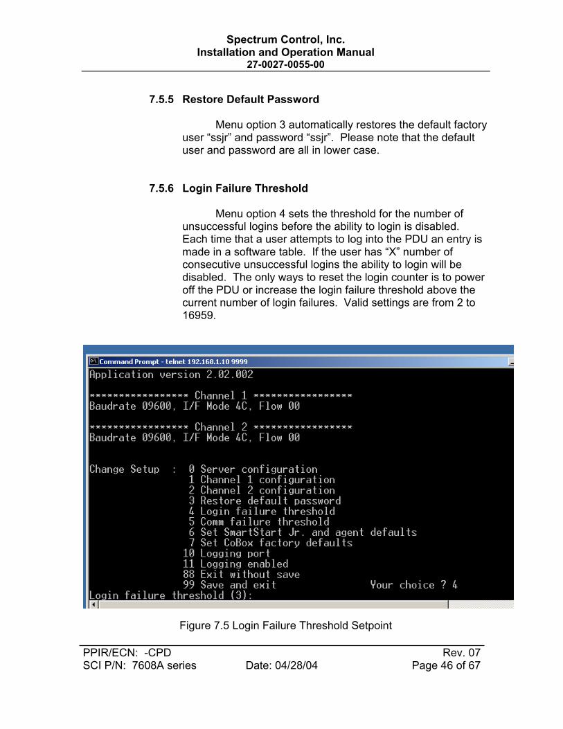
7.5.6 Login Failure Threshold
Menu option 4 sets the threshold for the number of unsuccessful logins before the ability to login is disabled. Each time that a user attempts to log into the PDU an entry is made in a software table. If the user has “X” number of consecutive unsuccessful logins the ability to login will be disabled. The only ways to reset the login counter is to power off the PDU or increase the login failure threshold above the current number of login failures. Valid settings are from 2 to 16959.
Figure 7.5 Login Failure Threshold Setpoint

Spectrum Control, Inc. Installation and Operation Manual
27-0027-0055-00
PPIR/ECN: -CPD Rev. 07 SCI P/N: 7608A series Date: 04/28/04 Page 47 of 67
7.5.7 Communication Failure Threshold
Menu option 5 sets the threshold for the number of
communication failures within the PDU before an alert is broadcasted. If the LAN module and internal PDU microprocessor stop communicating or become out of synchronization an entry is made in a software table. Once the number of communication errors exceeds the setpoint a SNMP alert is sent notifying the user or administrator of a communication error and that unit will need to be serviced or replaced. The entries in the software table are cumulative as long as the PDU is powered on. Upon power down the software table is reset. Valid settings are from 2 to16959.
Figure 7.6 Communication Failure Threshold Setpoint
7.5.8 Set SSJR and LAN Module to Factory Defaults
Menu option 6 restores all PDU and LAN module defaults back to the factory settings. This command will ensure that both the LAN module and internal PDU microprocessor are returned to identical communication

Spectrum Control, Inc. Installation and Operation Manual
27-0027-0055-00
PPIR/ECN: -CPD Rev. 07 SCI P/N: 7608A series Date: 04/28/04 Page 48 of 67
settings. If changes are made using the commands in section 5.0 and the Smart Start Jr. PDU is no longer communicating use this menu selection to resort internal communications. PDU with LAN modules should have all configuration changes made using the LAN module configuration menu selections.
7.5.9 Set LAN Module to Factory Defaults
Select 7 to restores all factory settings in the LAN module LAN Module to the factory default settings. The server configurations remain unchanged.
7.5.10 Set LAN Module Logging Port
Select 10 to select the command logging port. When enabled the command logging feature will log the last commands received and processed by the PDU. The feature is used for security and troubleshooting purposes.
7.5.11 Enable Command Logging
Select 11 to enable logging of commands received and processed by the PDU. The commands will be displayed on the port selected by menu option 10. The feature is used for security and troubleshooting purposes.
7.5.12 Exit Configuration Mode
Select 88 exit the configuration mode without saving
any changes, or select 99 to exit and save all changes. All values are stored in nonvolatile RAM. The LAN Module will automatically reset but the state of the PDU outputs will not be affected.
7.6 WEB Interface
Remote users can monitor and control the Smart Start Jr. with a standard web browser. When the Smart Start Jr.’s “home page” is requested, the browser receives a web page containing an embedded Java applet. The applet establishes a connection with the agent and provides a user interface for monitoring and controlling the Smart Start Jr. Due to the amount of graphics and LAN connection

Spectrum Control, Inc. Installation and Operation Manual
27-0027-0055-00
PPIR/ECN: -CPD Rev. 07 SCI P/N: 7608A series Date: 04/28/04 Page 49 of 67
speeds within a network the initial page could take several seconds to display.
7.7 Monitor Screen
The device applet initially displays the following screen. Please note that this screen is slightly different for 1x8 vs. 2x4 models. The LAN module software reads its configuration from the PDU microprocessor and automatically displays the proper format for the application.
Figure 7.7 Web Interface Monitor Screen
The monitor screen contains the following items: Item Function Unit Name User-defined descriptive name of the unit. PDU Address Number between 0-255, identifies the Smart Start Jr. Firmware Version Version of the basic firmware running in the Smart Start Jr. Agent Version Version of the agent firmware running in the embedded LAN Module Configuration Standalone, Master, or Slave Unit Mode Remote or Local Temperature Displays the Celsius temperature of units equipped with a temperature sensor Voltage Input line voltage (separate channels shown on 2x4 units) Current Input line current (separate channels shown on 2x4 units) Frequency Input line frequency (separate channels shown on 2x4 units)

Spectrum Control, Inc. Installation and Operation Manual
27-0027-0055-00
PPIR/ECN: -CPD Rev. 07 SCI P/N: 7608A series Date: 04/28/04 Page 50 of 67
Outlet Status Indicators The on/off status of each outlet is shown by a green/red indicator, respectively. Login Button Allow the user to log into the unit to perform maintenance and control functions. Unit Setup Button Allows privileged users to set up and maintain basic unit information. Alert Setup Button Allows privileged users to set up and maintain alerts. Circuit Setup Button Allows privileged users to set up and maintain auxiliary circuit configuration. User Setup Button Allows privileged users to set up and maintain additional users. Outlet Control Button Allows privileged users to directly control outlets. About Button Displays identifying information about the applet.
7.7.1 LOGIN
The Login dialog box requests a username and
password. Each username has an associated set of privileges. Initially a single username and password are defined, “ssjr” and “ssjr”, respectively. This username has full privileges to set up, maintain, and control the unit. Additional users can be set up via the User Setup dialog, described below.
Figure 7.8 Web Interface Login Screen
When a username and password are entered, the
applet changes the enabled/disabled status of buttons throughout the applet to reflect the users’ privileges.

Spectrum Control, Inc. Installation and Operation Manual
27-0027-0055-00
PPIR/ECN: -CPD Rev. 07 SCI P/N: 7608A series Date: 04/28/04 Page 51 of 67
7.7.2 Setup
The unit setup dialog is used to set up and maintain basic operational parameters of the Smart Start Jr. and the network agent.
Figure 7.9 Unit Setup using Web Interface

Spectrum Control, Inc. Installation and Operation Manual
27-0027-0055-00
PPIR/ECN: -CPD Rev. 07 SCI P/N: 7608A series Date: 04/28/04 Page 52 of 67
The Unit Setup dialog contains the following items: Item Function Unit Name User-defined descriptive name of the unit. PDU Address Number between 0-255, identifies the Smart Start Jr. Master/Slave Configures the unit for standalone, master, or slave operation. Baud Rate Baud rate of the serial Smart Start Jr, serial interface. Current Limit A Shown as “Current Limit” on 1x8 units – indicates the maximum allowable current draw for
channel A, expressed in Amps. Current Limit B Not shown on 1x8 units – indicates the maximum allowable current draw for channel B,
expressed in Amps. Undervoltage Setpoint A Shown as “Undervoltage Setpoint” on 1x8 units – indicates the minimum allowable input
voltage for channel A, expressed in Volts. Undervoltage Setpoint B Not shown on 1x8 units – indicates the minimum allowable input voltage for channel A,
expressed in Volts. Sequence Delay The delay between outlets when turning on or off sequentially, expressed in seconds. Sequence The sequence in which outlets are turned on or off automatically. If an outlet number is not
entered in the sequence the outlet will remain at it’s current state (on or off) until power is removed from the unit.
Outlet Names Identifying names for each outlet. These names are displayed in the Outlet Control dialog window.
Group Names Identifying names for outlet groupings. These names are displayed in the Outlet Control dialog window.
Group Outlets Specify the outlet number associated with the given outlet grouping. Up to four outlets can be turned on or off simultaneously.
7.7.3 Alert Setup
The Alert Setup dialog lets the user set up and maintain
conditions that cause alerts, recipients who receive alerts, and other information related to alerts.

Spectrum Control, Inc. Installation and Operation Manual
27-0027-0055-00
PPIR/ECN: -CPD Rev. 07 SCI P/N: 7608A series Date: 04/28/04 Page 53 of 67
Figure 7.10 Web Interface Alert Setup Alerts and related actions can be set up for the following events:
• High input voltage • Low input voltage • High current draw • High temperature • Monitored host not detected
The Alert Setup dialog contains the following items: Item Function Voltage High Alert Input voltage at which a high-voltage alert is issued. Voltage Low Alert Input voltage at which a low-voltage alert is issued. Current Alert Current draw at which a high-current alert is issued. Temp Alert Temperature at which a high-temperature alert is issued. Ping Interval Seconds between attempts to contact a monitored host. Ping Time-out Milliseconds to wait for a “ping” response from a monitored host. Ping Threshold Number of times a “ping” fails before an alert is issued and the outlet associated with the
monitored host is turned off. Restart Delay Number of seconds to wait before turning on the outlet associated with a monitored host that
has been turned off due to a “ping” failure. Host 1-8 IP addresses of monitored hosts associated with outlets 1-8, respectively. Host 1-8 check box Check box to enable Ping feature for host. Host Test Buttons Pings the associated host and reports the result in a popup dialog box. E-mail Recipients E-mail addresses of up to three e-mail alert recipients. E-mail Test Buttons Sends a test e-mail to the associated e-mail recipient as a test. Trap Recipients IP addresses of up to three SNMP trap recipients. SMTP server IP address of SMTP server used to issue e-mail alerts. E-mail Host ID Fully qualified host name to be used in e-mail alerts (can often be ignored or set to “foo”) From Address Return address appearing on e-mail alerts.
7.7.4 Circuit Setup
The Circuit Setup dialog lets the user set up and
maintain conditions that cause alerts, recipients who receive alerts, and other information related to alerts.

Spectrum Control, Inc. Installation and Operation Manual
27-0027-0055-00
PPIR/ECN: -CPD Rev. 07 SCI P/N: 7608A series Date: 04/28/04 Page 54 of 67
Figure 7.11 Web Interface External Circuit Setup Alerts and related actions can be set up for the following events:
• External circuit 1 opened • External circuit 2 opened • External contact 1 voltage/current/temperature • External contact 2 voltage/current/temperature
The Circuit Setup dialog contains the following items: Item Function Circuit 1 Active Checkbox indicating whether external circuit 1 is being monitored. Circuit 1 Message Message sent with alerts when circuit 1 is opened while monitored. Circuit 2 Active Checkbox indicating whether external circuit 2 is being monitored. Circuit 2 Message Message sent with alerts when circuit 2 is opened while monitored. External Contact 1 Select variable when external contact change state (Voltage/Current/Temperature or Manual)
Values used for trigger points are based on settings in the alert setup screen. Note when 2X4 configuration is used Contact 1 is tied to Channel A.
External Contact 2 Select variable when external contact change state (Voltage/Current/Temperature or Manual) Values used for trigger points are based on settings in the alert setup screen. Note when 2X4 configuration is used Contact 2 is tied to Channel B.

Spectrum Control, Inc. Installation and Operation Manual
27-0027-0055-00
PPIR/ECN: -CPD Rev. 07 SCI P/N: 7608A series Date: 04/28/04 Page 55 of 67
7.7.5 User Setup
The User Setup Dialog allows usernames, passwords,
and privileges to be set up and maintained for up to eight users. When a user logs in, the functions he or she can perform are determined by the privileges established in the User Setup Dialog. By default (on new units, for example), a single user “ssjr”, password “ssjr” is defined with full privileges. Do not use “Non standard” characters, use numbers and letters only when creating usernames and passwords.
Figure 7.12 WEB User Setup Screen The User Setup dialog contains the following items for each defined user: Item Function Username Case-sensitive user name. Password Case-sensitive password. Outlet Control Privileges 1-8 If checked, the user may turn the specified outlet on or off, including sequenced operations. Group Setup Privilege If checked, the user may turn the specified group on or off. Unit Setup Privilege If checked, the user may set up and maintain basic unit parameters Alert Setup Privilege If checked, the user may set up and maintain alerts. User Setup Privilege If checked, the user may set up and maintain users.

Spectrum Control, Inc. Installation and Operation Manual
27-0027-0055-00
PPIR/ECN: -CPD Rev. 07 SCI P/N: 7608A series Date: 04/28/04 Page 56 of 67
7.7.6 Outlet Control
The Outlet Control dialog allows direct control of the Smart Start Jr. outlets, either individually or in sequenced operations. The exact items displayed and whether they are enabled depends on the type of unit (1x8 or 2x4) and the privileges of the currently logged-in user. If an outlet is manually turned off it will not be included in the automatic or power on sequences.
Figure 7.13 Web Interface Outlet Control The Outlet Control dialog contains the following items: Item Function Outlet Names Names of outlets as defined in the Unit Setup dialog. Outlet On/Off Buttons Turns the associated outlet on or off Outlet Group Names Names of outlet groups as defined in the Unit Setup dialog. Outlet Group On/Off Buttons Turns the associated outlet group on or off On Sequential Buttons Sequences on outlets (all outlets, channel A outlets, or channel B outlets) Off Sequential Buttons Sequences off outlets (all outlets, channel A outlets, or channel B outlets) Off Simultaneous Turns off all outlets simultaneously.

Spectrum Control, Inc. Installation and Operation Manual
27-0027-0055-00
PPIR/ECN: -CPD Rev. 07 SCI P/N: 7608A series Date: 04/28/04 Page 57 of 67
7.7.7 About
The About dialog displays identifying information about the agent software and provides Spectrum Control contact information and web/e-mail links.
Figure 7.14 Web Interface About Screen 7.8 SNMP and SMTP E-Mail Alerts
Smart Start Network Agent software includes an SNMP agent,
which provides read-only and read-write access to a limited number of variables. These are defined in an SNMP MIB and are shown in the following sections. 7.8.1 SNMP Variables
The OID’s shown in this table are relative to the enterprise OID 1.3.6.1.4.1.11923. Variable Access Description OID devcLineVoltageA read-only Line voltage for channel A, units are Volts x 10 1.1.1.1.1.1 devcLineVoltageB read-only Line voltage for channel B, units are Volts x 10 1.1.1.1.1.2 devcLoadCurrentA read-only Total load current for channel A, units are Amps x 100 1.1.1.1.1.3 devcLoadCurrentB read-only Total load current for channel B, units are Amps x 100 1.1.1.1.1.4 devcLineFrequencyA read-only Line frequency for channel A, units are Hz x 10 1.1.1.1.1.5 devcLineFrequencyB read-only Line frequency for channel B, units are Hz x 10 1.1.1.1.1.6 devcTemperature read-only Temp reading from optional external probe, units are degrees C x 10 1.1.1.1.1.7 devcSequence read-only Each char position contains a digit corresponding to an outlet number 1.1.1.1.1.8 devcSequenceDelay read-only Time delay between each outlet turning on or off in tenths of a second 1.1.1.1.1.9

Spectrum Control, Inc. Installation and Operation Manual
27-0027-0055-00
PPIR/ECN: -CPD Rev. 07 SCI P/N: 7608A series Date: 04/28/04 Page 58 of 67
devcPDUAddres read-only PDU address (0 to 255) 1.1.1.1.1.10 devcMasterSlave read-only Master/slave setting): 1 = standalone, 2 = master, 3 = slave 1.1.1.1.1.11 devcSoftwareVersion read-only Microprocessor software version 1.1.1.1.1.12 optdBaudRate read-only Baud rate: 1 = 4800, 2 = 9600, 3 = 19200, 4 = 38400 1.1.1.1.2.1 optdOutletsOffSimultaneous read-write Turn off all outlets simultaneously 1.1.1.1.2.2 optdPowerOnCurrentLimitA read-only Power-on current limit for channel A, units are Amps x 10 1.1.1.1.2.3 optdPowerOnCurrentLimitB read-only Power-on current limit for channel A, units are Amps x 10 1.1.1.1.2.4 optdOutletsOnAll read-write Turns on outlets 1-8 in sequence: 1 = execute 1.1.1.1.2.5 OptdOutletsOnA read-write Turns on outlets 1-4 in sequence: 1 = execute 1.1.1.1.2.6 OptdOutletsOnB read-write Turns on outlets 5-8 in sequence: 1 = execute 1.1.1.1.2.7 OptdOutletsOffAll read-write Turns off outlets 1-8 in reverse sequence: 1 = execute 1.1.1.1.2.8 OptdOutletsOffA read-write Turns on outlets 1-4 in reverse sequence: 1 = execute 1.1.1.1.2.9 OptdOutletsOffB read-write Turns on outlets 5-8 in reverse sequence: 1 = execute 1.1.1.1.2.10 optdOutletDirect1 read-only On/off status of outlet 1: 1 = off, 2 = on 1.1.1.1.2.11 optdOutletDirect2 read-only On/off status of outlet 2: 1 = off, 2 = on 1.1.1.1.2.12 optdOutletDirect3 read-only On/off status of outlet 3: 1 = off, 2 = on 1.1.1.1.2.13 optdOutletDirect4 read-only On/off status of outlet 4: 1 = off, 2 = on 1.1.1.1.2.14 optdOutletDirect5 read-only On/off status of outlet 5: 1 = off, 2 = on 1.1.1.1.2.15 optdOutletDirect6 read-only On/off status of outlet 6: 1 = off, 2 = on 1.1.1.1.2.16 optdOutletDirect7 read-only On/off status of outlet 7: 1 = off, 2 = on 1.1.1.1.2.17 optdOutletDirect8 read-only On/off status of outlet 8: 1 = off, 2 = on 1.1.1.1.2.18 optdUnitMode read-only Unit mode is local or remote: 1 = remote, 2 = local 1.1.1.1.2.20 optdUndervoltageSetpointA read-only Undervoltage dropout setpoint for channel A, units are Volts 1.1.1.1.2.21 optdUndervoltageSetpointB read-only Undervoltage dropout setpoint for channel B, units are Volts 1.1.1.1.2.22 optdSetFactoryDefaults read-only Changes all settings back to factory: 1 = execute 1.1.1.1.2.23 ThrsVoltageHigh read-only Threshold voltage triggering overvoltage trap, units are volts x 10 1.1.1.1.3.1 ThrsVoltageLow read-only Threshold voltage triggering undervoltage trap, units are volts x 10 1.1.1.1.3.2 ThrsCurrentHigh read-only Threshold current triggering overcurrent trap, units are amps x 100 1.1.1.1.3.5 ThrsTemperatureHigh read-only Threshold temp triggering overtemp trap, units are degrees C x 10 1.1.1.1.3.13 ThrsLoginFail read-only Number of login failures triggering error 1.1.1.1.3.14 ThrsCommFail read-only Number of comm failures triggering error 1.1.1.1.3.15 circRemoteMessage1 read-only Remote message 1 text 1.1.1.1.4.1 circRemoteMessage2 read-only Remote message 2 text 1.1.1.1.4.2 circActive1 read-only Auxiliary contact circuit 1: 1 = inactive, 2 = active 1.1.1.1.4.3 circActive2 read-only Auxiliary contact circuit 2: 1 = inactive, 2 = active 1.1.1.1.4.4 circOpenCircuit read-only Circuit causing open-circuit trap: 0 = none, 1 = circuit 1, 2 = circuit 2 1.1.1.1.4.5 snmpTrapRecipient1 read-only IP address of trap recipient 1 1.1.1.1.5.1 snmpTrapRecipient2 read-only IP address of trap recipient 2 1.1.1.1.5.2 snmpTrapRecipient3 read-only IP address of trap recipient 3 1.1.1.1.5.3 smtpServerAddress read-only IP address of SMTP server 1.1.1.1.6.1 smtpUserName read-only User name optionally used by some SMTP servers for authentication 1.1.1.1.6.2 smtpPassword read-only Password optionally used by some SMTP servers for authentication 1.1.1.1.6.3 smtpHostID read-only Host.domain of e-mail sender 1.1.1.1.6.4 smtpFrom read-only E-mail address of the sender 1.1.1.1.6.5 smtpEmailRecipient1 read-only E-mail address of recipient 1 1.1.1.1.6.6 smtpEmailRecipient2 read-only E-mail address of recipient 2 1.1.1.1.6.7 smtpEmailRecipient3 read-only E-mail address of recipient 3 1.1.1.1.6.8 pingHost1 read-only IP address of host powered by outlet 1 1.1.1.1.7.1 pingHost2 read-only IP address of host powered by outlet 2 1.1.1.1.7.2 pingHost3 read-only IP address of host powered by outlet 3 1.1.1.1.7.3 pingHost4 read-only IP address of host powered by outlet 4 1.1.1.1.7.4 pingHost5 read-only IP address of host powered by outlet 5 1.1.1.1.7.5 pingHost6 read-only IP address of host powered by outlet 6 1.1.1.1.7.6 pingHost7 read-only IP address of host powered by outlet 7 1.1.1.1.7.7 pingHost8 read-only IP address of host powered by outlet 8 1.1.1.1.7.8 PingInterval read-only Interval between pings in sec. Zero disables the ping feature 1.1.1.1.7.9 pingTimeout read-only Time-out in milliseconds before ping attempt fails 1.1.1.1.7.10 pingFailThreshold read-only Number of failed pings before device is power-cycled 1.1.1.1.7.11 pingFailedHost read-only Most recently failed host 1.1.1.1.7.13 pingHostEnabled1 read-only Ping host enablement flag 1, 1 = disabled, 2 = enabled 1.1.1.1.7.14 pingHostEnabled2 read-only Ping host enablement flag 2, 1 = disabled, 2 = enabled 1.1.1.1.7.15

Spectrum Control, Inc. Installation and Operation Manual
27-0027-0055-00
PPIR/ECN: -CPD Rev. 07 SCI P/N: 7608A series Date: 04/28/04 Page 59 of 67
pingHostEnabled3 read-only Ping host enablement flag 3, 1 = disabled, 2 = enabled 1.1.1.1.7.16 pingHostEnabled4 read-only Ping host enablement flag 4, 1 = disabled, 2 = enabled 1.1.1.1.7.17 pingHostEnabled5 read-only Ping host enablement flag 5, 1 = disabled, 2 = enabled 1.1.1.1.7.18 pingHostEnabled6 read-only Ping host enablement flag 6, 1 = disabled, 2 = enabled 1.1.1.1.7.19 pingHostEnabled7 read-only Ping host enablement flag 7, 1 = disabled, 2 = enabled 1.1.1.1.7.20 pingHostEnabled8 read-only Ping host enablement flag 8, 1 = disabled, 2 = enabled 1.1.1.1.7.21 PingRestartDelay1 read-only Interval to wait before powering-on outlet 1 in seconds 1.1.1.1.7.22 PingRestartDelay2 read-only Interval to wait before powering-on outlet 2 in seconds 1.1.1.1.7.23 PingRestartDelay3 read-only Interval to wait before powering-on outlet 3 in seconds 1.1.1.1.7.24 PingRestartDelay4 read-only Interval to wait before powering-on outlet 4 in seconds 1.1.1.1.7.25 PingRestartDelay5 read-only Interval to wait before powering-on outlet 5 in seconds 1.1.1.1.7.26 PingRestartDelay6 read-only Interval to wait before powering-on outlet 6 in seconds 1.1.1.1.7.27 PingRestartDelay7 read-only Interval to wait before powering-on outlet 7 in seconds 1.1.1.1.7.28 PingRestartDelay8 read-only Interval to wait before powering-on outlet 8 in seconds 1.1.1.1.7.29 unitName read-only Descriptive name of Smart Start Jr. unit 1.1.1.1.8.1 unitLoginFailCount read-only Login failure count 1.1.1.1.8.2 unitCommFailCount read-only Communication failure count 1.1.1.1.8.3
7.8.2 SNMP Traps
SNMP traps are issued if trap recipients have been specified and any of the following conditions occur:
• Line voltage A greater than or equal to high threshold • Line voltage A less than or equal to low threshold • Line voltage B greater than or equal to high threshold • Line voltage B less than or equal to low threshold • Load current A greater than or equal to high threshold • Load current B greater than or equal to high threshold • Temperature greater than or equal to high threshold • Ping failure threshold exceeded for host • Remote circuit opened • Login failure, logins disabled • Serial communications between the Smart Start Jr. and the
LAN module failed • Test only
7.8.3 SMTP (E-mail Alerts)
E-mails are issued if e-mail recipients have been specified and any of the following conditions occur:
• Line voltage A greater than or equal to high threshold • Line voltage A less than or equal to low threshold • Line voltage B greater than or equal to high threshold • Line voltage B less than or equal to low threshold • Load current A greater than or equal to high threshold • Load current B greater than or equal to high threshold

Spectrum Control, Inc. Installation and Operation Manual
27-0027-0055-00
PPIR/ECN: -CPD Rev. 07 SCI P/N: 7608A series Date: 04/28/04 Page 60 of 67
• Temperature greater than or equal to high threshold • Ping failure threshold exceeded for host • Remote circuit opened • Login failure, logins disabled • Serial communications between the Smart Start Jr. and the
LAN module failed
7.8 Device Organizer
The Device Organizer is installed separately on the user’s computer and provides a way to organize and access multiple Smart Start Jr. network agents.
7.9.1 Main Screen
Devices (network enabled Smart Start Jr.s) are organized in a tree structure on the left side of the main screen. The tree contains “groups” and “devices”.

Spectrum Control, Inc. Installation and Operation Manual
27-0027-0055-00
PPIR/ECN: -CPD Rev. 07 SCI P/N: 7608A series Date: 04/28/04 Page 61 of 67
Figure 7.15 Web Interface Device Organizer
Groups are identified by a handle icon, which allows the group to expanded or collapsed to show or hide the contained items. Groups can contain other groups or devices. Right-clicking an item in the tree or selecting the “Edit” menu item displays the edit menu, shown below:
7.9.2 Edit Menu
Figure 7.16 Device Organizer Edit Menu
The menu contains the following items:
Item Function Copy Copies the item (and any sub-items) to the clipboard Cut Copies the item (and any sub-items) to the clipboard and deletes it from the tree Paste Append Pastes the item on the clipboard at the end of the sublist belonging to the selected item. Paste Insert Pastes the item on the clipboard immediately before the selected item and at the same level. Insert Displays the Device Node dialog and inserts the result before the selected item. Append Displays the Device Node dialog and appends the result to the sublist belonging to the
selected item. Delete Remove the selected item and all sub-items. Edit Displays the selected item in the Device Node dialog. Connect (same window) Connects to the network agent identified by the selected item and displays the Device Applet
in the panel on the right side of the screen. Connect (new window) Connects to the network agent identified by the selected item and displays the Device Applet
in a new browser window.
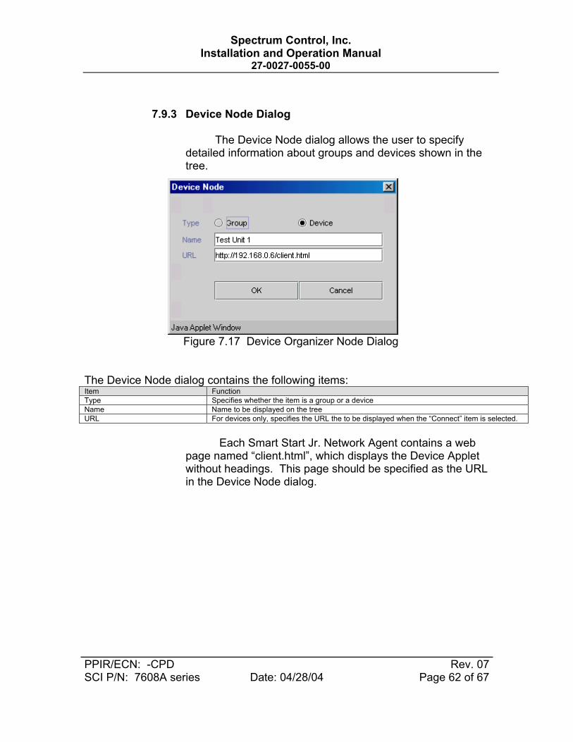
Spectrum Control, Inc. Installation and Operation Manual
27-0027-0055-00
PPIR/ECN: -CPD Rev. 07 SCI P/N: 7608A series Date: 04/28/04 Page 62 of 67
7.9.3 Device Node Dialog
The Device Node dialog allows the user to specify detailed information about groups and devices shown in the tree.
Figure 7.17 Device Organizer Node Dialog The Device Node dialog contains the following items: Item Function Type Specifies whether the item is a group or a device Name Name to be displayed on the tree URL For devices only, specifies the URL the to be displayed when the “Connect” item is selected.
Each Smart Start Jr. Network Agent contains a web
page named “client.html”, which displays the Device Applet without headings. This page should be specified as the URL in the Device Node dialog.

Spectrum Control, Inc. Installation and Operation Manual
27-0027-0055-00
PPIR/ECN: -CPD Rev. 07 SCI P/N: 7608A series Date: 04/28/04 Page 63 of 67
8.0 Maintenance and Replacement parts
There are no user serviceable parts inside the PDU. In the event there is an electronic problem the unit please contact the factory.
9.0 Warranty
Under normal use and specified operation conditions the Smart Start Jr PDU is warranted from the day of delivery for a period of one year. During this period, if the product should fail, the device can be sent back to the factory for repair or replacement at the discretion of Spectrum Control.
If the device is misused or tampered with in any way the warranty
becomes invalid. SCI is not liable for any damage caused by products that have been modified or serviced by other parties.

Spectrum Control, Inc. Installation and Operation Manual
27-0027-0055-00
PPIR/ECN: -CPD Rev. 07 SCI P/N: 7608A series Date: 04/28/04 Page 64 of 67
APPENDIX A Network Notation Basics and IP Addressing
1.0 IP Addresses
Each TCP/IP node on a network host has a unique IP address. This address provides the information needed to forward packets on the local network and across multiple networks if necessary.
IP addresses are specified as x.x.x.x, where each x is a number from
0 to 255; for example, 192.0.1.99. The LAN Module must be assigned a unique IP address to use TCP/IP network functionality.
IP addresses contain three pieces of information: the network, the
subnet, and the host.
1.0.1 Network Portion
The network portion of the IP address is determined by the network type: Class A, B, or C. The most common setting for use with the SSJR PDU is Class C.
Table 1: Network Portion of IP Address
Network Class Network Portion of Address Class A First byte (2nd, 3rd, and 4th bytes are the host) Class B First 2 bytes (3rd and 4th bytes are the host) Class C First 3 bytes (4th byte is the host)
In most network examples, the host portion of the address is set to zero.
Table 2: Available IP Addresses Class Reserved Available A 0.0.0.0
127.0.0.0 1.0.0.0 to 126.0.0.0
B 128.0.0.0 191.255.0.0
128.1.0.0 to 191.254.0.0
C 192.0.0.0 225.255.255.0
192.0.1.0 to 225.255.255.0

Spectrum Control, Inc. Installation and Operation Manual
27-0027-0055-00
PPIR/ECN: -CPD Rev. 07 SCI P/N: 7608A series Date: 04/28/04 Page 65 of 67
Consider the IP address 36.1.3.4. This address is a Class A address; therefore, the network portion of the address is 36.0.0.0 and the host portion is 1.3.4.
1.0.2 Subnet Portion
The subnet portion of the IP address represents which sub-network the address is from. Sub-networks are formed when an IP network is broken down into smaller networks using a subnet mask.
A router is required between all networks and all sub-
networks. Generally, hosts can send packets directly only to hosts on their own sub-network. All packets destined for other subnets are sent to a router on the local network.
1.0.3 Host Portion
The host portion of the IP address is a unique number assigned to identify the host.
1.0.3.1 Network Address
A host address with all host bits set to 0 addresses the
network as a whole (for example, in routing entries).
Figure 1: Sample Network Address
1.0.3.2 Broadcast Address
A host address with all host bits set to 1 is the broadcast address, meaning for “for every station.”
Figure 2: Sample Broadcast Address
192.168.1.0
192.168.1.25

Spectrum Control, Inc. Installation and Operation Manual
27-0027-0055-00
PPIR/ECN: -CPD Rev. 07 SCI P/N: 7608A series Date: 04/28/04 Page 66 of 67
Network and broadcast addresses must not be used as a host address; for example, 192.168.1.0 identifies the entire network, and 192.168.1.255 identifies the broadcast address.
1.0.3.3 IP Subnet Mask
An IP subnet mask divides IP address differently than the standards defined by the classes A, B, and C. An IP subnet mask defines the number of bits to be taken from the IP address as the network or host sections. The LAN Module prompts for the number of host bits to be entered and then calculates the netmask, which is displayed in standard decimal-dot notation (for example, 255.255.255.0) when saved parameters are displayed.
Table 3: Standard IP Network Netmasks Network Class Network Bits Host Bits Netmask A 8 24 255.0.0.0 B 16 16 2555.255.0.0 C 24 8 255.255.255.0
Table 4: Netmask Examples
Netmask Host Bits 255.255.255.252 2 255.255.255.248 3 255.255.255.240 4 255.255.255.224 5 255.255.255.192 6 255.255.255.128 7 255.255.255.0 8 255.255.254.0 9 255.255.252.0 10 255.255.248.0 11 … … 255.128.0.0 23 255.0.0.0 24
1.0.2.4 Private IP Networks and the Internet
If your network is not and will not be connected to the
Internet, you may use any IP address. If your network is connected or will be connected to the Internet, or if you intend to operate the LAN Module on an intranet, you should use one

Spectrum Control, Inc. Installation and Operation Manual
27-0027-0055-00
PPIR/ECN: -CPD Rev. 07 SCI P/N: 7608A series Date: 04/28/04 Page 67 of 67
of the reserved sub-networks. Consult you network administrator with questions about IP address assignment.
1.0.2.5 Network RFCs
For more information about IP addresses, refer to the
following documents, which can be located on the World Wide Web using one of the following directories or indices:
• RFC 950 Internet Standard Subnetting Procedure • RFC 1700 Assigned Numbers • RFC 1117 Internet Numbers • RFC 1597 Address Allocation for Private Networks