specifying crosstalk - ieee 802 · 18 ay 4, 2 05 (r1. ) channel m odel ad hoc conclusions...
TRANSCRIPT

Specifying Crosstalk
Adam Healey
Agere Systems
May 4, 2005

Channel Model Ad Hoc2 May 4, 2005 (r1.0)
Proposal
� Use the power-sum crosstalk (MDNEXT and MDFEXT) limits proposed by D’Ambrosia et al. [1] as the normative specification for crosstalk.
• Supplement this proposal with single-aggressor NEXT and single-aggressor FEXT limits.
� For link budget purposes, model crosstalk amplitude as a Gaussian random variable with zero mean and variance equal to the average crosstalk power.
• Average crosstalk power is directly related to power-sum crosstalk.
[1] D’Ambrosia et al., “Proposed Changes to the NEXT/FEXT Informative Mask Set”, September 2004.http://ieee802.org/3/ap/public/sep04/dambrosia_03_0904.pdf

Channel Model Ad Hoc3 May 4, 2005 (r1.0)
Definition: Average Crosstalk Power
� Assume each aggressor is asynchronous with respect to the victim and the other aggressors.
� Also assume that, at the receiver, victim and aggressor symbols are independent, identically distributed events.
• stationary and uncorrelated
� The average crosstalk power is the sum of the average power of the individual aggressors.
� The average power of an individual aggressor is the time average of the squared voltage (assuming zero mean).
� The frequency-domain interpretation is described on the following slides.

Channel Model Ad Hoc4 May 4, 2005 (r1.0)
Mathematical Model
� Si(f) is the input PSD
• A is the symbol amplitude
• T is baud time
• symbols are independent and identically distributed
� Ht(f) is the transmitter pulse shaping filter
� Hn(f) is transfer function of the nth crosstalk channel
� Hr(f) is the receiver filter
� Ro(0) is the average crosstalk power
)( fHr)( fHt )(1 fH
)( fHt )( fHn
)( fSi
)( fSi
)( fSo
. . .
. . .
)( fHt )(2 fH)( fSi
( )fTTAfSi22 sinc)( =
2)()()()( fHfHfHfG rntn =
�=n
nio fGfSfS )()()(
�∞
∞−
= dffSR oo )()0(
Channel Model Ad Hoc5 May 4, 2005 (r1.0)
Relationship to Power-Sum Crosstalk
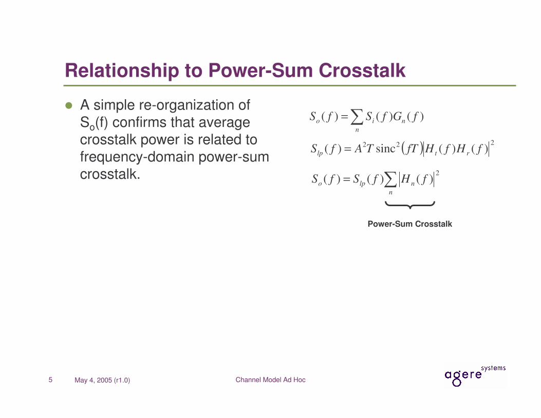
� A simple re-organization of So(f) confirms that average crosstalk power is related to frequency-domain power-sum crosstalk.
�=n
nio fGfSfS )()()(
�=n
nlpo fHfSfS2
)()()(
( ) 222 )()(sinc)( fHfHfTTAfS rtlp =
Power-Sum Crosstalk

Channel Model Ad Hoc6 May 4, 2005 (r1.0)
Comparison to Moore
� The treatment of crosstalk presented by Moore [2] has been suggested as a standard to which other methods can be compared.
� It should noted that Moore’s treatment is very similar to Statistical Eye analysis.
[2] Moore, “Computing the Effects of Crosstalk Using Convolution”, March 2005.http://ieee802.org/3/ap/public/channel_adhoc/moore_c1_0305.pdf

Channel Model Ad Hoc7 May 4, 2005 (r1.0)
Model Assumptions
� Assume a simple trapezoidal pulse with rise time Tr
� No receive filtering
� No package models
� A = 400 mVp
� T = 97 ps (10.3125Gb/s)
� Tr = 24 ps (from Draft 0.9)
��
���
�=6.0
sinc)( rt
TffH
1)( =fHr
( ) ��
���
�=6.0
sincsinc)( 222 rlp
TffTTAfS
T
A
A−
0
A6.0
A6.0−rT

Channel Model Ad Hoc8 May 4, 2005 (r1.0)
RMS and Peak Crosstalk Comparison
z0 = 7.0345 for 1E-12Convolution (Moore) Analysis:Number of Phases = 16PDF Bin Size = 2-11 V

Channel Model Ad Hoc9 May 4, 2005 (r1.0)
Peak Crosstalk vs. Test Case
Tyco
Intel
Molex
Gaussian Prediction
MooreAnalysis
Channel Model Ad Hoc10 May 4, 2005 (r1.0)
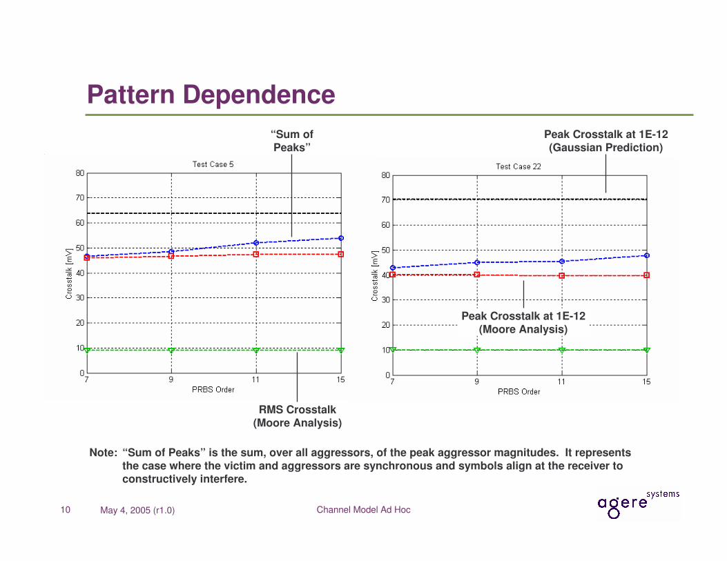
Pattern Dependence
RMS Crosstalk(Moore Analysis)
Peak Crosstalk at 1E-12(Moore Analysis)
“Sum ofPeaks”
Peak Crosstalk at 1E-12(Gaussian Prediction)
Note: “Sum of Peaks” is the sum, over all aggressors, of the peak aggressor magnitudes. It represents the case where the victim and aggressors are synchronous and symbols align at the receiver to constructively interfere.

Channel Model Ad Hoc11 May 4, 2005 (r1.0)
Observations
� As expected, the RMS crosstalk predicted by the Moore methodology aligns well the value Ro(0) derived from the frequency-domain power-sum crosstalk.
� While the Moore treatment produces a Gaussian-like distribution function, the Gaussian prediction is more pessimistic.
• This is an acceptable property from a link budget perspective.

Channel Model Ad Hoc12 May 4, 2005 (r1.0)
Crosstalk Amplitude Adjustment
� Average crosstalk power is influenced by the following serdes parameters:
• Transmit symbol amplitude— � amplitude, � crosstalk
• Transmitter rise time— � rise time, � crosstalk
• Receiver bandwidth— � bandwidth, � crosstalk
• Equalizer transfer function

Channel Model Ad Hoc13 May 4, 2005 (r1.0)
Power-Sum Crosstalk Limits (Example)
��
���
�+−≤ 1010 10log5.725)(
ffMDNEXT �
�
���
�+−≤ 1010 10log1521)(
ffMDFEXT
��
���
�= �n
n fNEXTfMDNEXT2
10 )(log10)( ��
���
�= �n
n fFEXTfMDFEXT2
10 )(log10)(

Channel Model Ad Hoc14 May 4, 2005 (r1.0)
Total Crosstalk (example)
���
����
�+= 10
)(10
)(
10 1010log10)(fMDFEXTfMDNEXT
fPSXT
��
���
�+−≤ 1010 10log1320)(
ffPSXT
Note that:
10)(
10)()(fPSXT
lpo fSfS ≤
�∞
∞−
≤ dffSRfPSXT
lpo10
)(
10)()0(
Using Slp( f ) from slide 7 and this example PSXT( f ), Ro( 0 ) < 17 mVrms.
This aligns well with the computed values shown on slide 8.

Channel Model Ad Hoc15 May 4, 2005 (r1.0)
Power-Sum Considerations
� The power-sum implies that the victim and aggressors are asynchronous and uncorrelated.
� However, what happens when the victim and aggressors share a common clock, and the symbols align at the RX such that they constructively interfere?
• It is unlikely that such a fortuitous alignment will occur over all aggressors.
• However, it is reasonable to assume that an aggressor may share a deterministic relationship with the victim.
� Therefore, add a specification for an individual aggressor so that the impact of a “worst-case” deterministic relation-ship to the victim may be limited.

Channel Model Ad Hoc16 May 4, 2005 (r1.0)
Single-Aggressor Crosstalk Limits (Example)
��
���
�+−≤ 1010 10log5.728)(
ffNEXTn �
�
���
�+−≤ 1010 10log5.724)(
ffFEXTn

Channel Model Ad Hoc17 May 4, 2005 (r1.0)
Attenuation-to-Crosstalk Ratio (ACR)
� An Attenuation-to-Crosstalk Ratio (ACR) limit has been proposed to allow more crosstalk for channels with lower loss and less crosstalk for channels with higher loss.
� It prevents loss and crosstalk from assuming worst-case values simultaneously.
� It also prevents NEXT and FEXT from assuming worst-case values simultaneously.
� A normative embodiment of ACR will be proposed once the mechanics of a normative “loss” specification have been determined.

Channel Model Ad Hoc18 May 4, 2005 (r1.0)
Conclusions
� Time-domain RMS crosstalk can be directly derived from frequency-domain power-sum crosstalk.
� Modeling crosstalk as a Gaussian amplitude distribution provides an upper bound to the distribution derived from empirical analysis.
• A quick and conservative estimate of the peak crosstalk may be computed as z0 times the RMS crosstalk.
� Single aggressor crosstalk limits may used to bound the crosstalk contribution of an aggressor who happens to be synchronous and correlated to the victim.

Channel Model Ad Hoc19 May 4, 2005 (r1.0)
Future Work
� Determine appropriate placement of the limit intercepts based on simulated link performance and design trade-offs.
• Some of the 23 test channels may not be supported due to excessive crosstalk.
� Estimate peak crosstalk for patterns beyond PRBS-15 to further investigate the utility of the Gaussian model as a bounding case.
� Investigate the applicability to the 1000BASE-KX and 10GBASE-KX4 cases.