specifier reports: lighting circuit power reducers ... er reports lighting circuit power reducers...
TRANSCRIPT

Specifier ReportsLighting Circuit Power Reducers
Volume 6 Number 2 September 1998 (Revised October 1998)
ContentsIntroduction ............................................... 1Background ............................................... 1Performance Characteristics ................... 3Performance Evaluations ......................... 7Alternative Technologies ....................... 10Further Information ............................... 12Data Table Terms and Definitions ........ 13Manufacturer-Supplied Information ..... 14NLPIP-Measured Data ........................... 15Publication Information ......................... 16Ordering Information ............................. 16
Program Sponsors
Energy Center of Wisconsin
Iowa Energy Center
New York State Energy Research and Development Authority
Northwest Energy Efficiency Alliance
U.S. Environmental Protection Agency
Introduction
Lighting circuit power reducers are retrofit devices designed toreduce the energy use of a lighting circuit. These power reducers,also called lighting controllers, are installed at electrical panelsbetween a circuit breaker and the lighting load to reduce the activepower of the entire lighting circuit. Reducing the lighting load,however, reduces illuminances and may also reduce system efficacy.
Manufacturers may claim that lighting circuit power reducerssave energy without a perceptible reduction in light output. Theirproduct catalogs contain many anecdotal reports of successfulapplications. However, there are few test data that support theseclaims and anecdotes. NLPIP produced this report to provideinformation about lighting circuit power reducers to specifiers.NLPIP tested products for single-phase fluorescent lighting systemsfrom three manufacturers for this report. The report also includesinformation on products for HID lighting systems, although NLPIPdid not test these products.
Background
Lighting circuit power reducers reduce the active power of alighting circuit. This issue of Specifier Reports focuses on thosewhich reduce active power by a discrete amount. There are twotypes available in the market: autotransformer lighting circuitpower reducers and electronic lighting circuit power reducers.
Manufacturers use the cost savings from the reduced power tojustify the initial cost of lighting circuit power reducers, usuallyover $1000 per unit.
2 Specifier Reports: Lighting Circuit Power Reducers
Autotransformer Lighting CircuitPower Reducers
Autotransformer lighting circuit powerreducers reduce the voltage supplied tothe lighting load (see the sidebar, “Auto-transformers”), but they preserve thevoltage waveform from the line to the loadand have little, if any, effect on powerquality. Reducing voltage, however, canaffect lamp and ballast performance.
Most of these products use variablestep autotransformers, and they are usedprimarily in high intensity discharge(HID) lamp systems with constant watt-age autotransformer (CWA) ballasts.Typically, they are heavy and bulky, oftenweighing more than 50 kilograms (110pounds). Many start and operate lamps atfull voltage for a time [often about 15–30minutes (min)] and then reduce voltage
gradually to maintain the stability of thelamp arc. Many of these devices also offervariable power reduction when operatingas part of a variable lighting controlsystem (photosensor control) or anenergy management system. This reportfocuses on the discrete power reductionapplications of these products.
Electronic Lighting Circuit PowerReducers
Electronic lighting circuit powerreducers typically decrease the root-mean-square (rms) voltage supplied tothe lighting load by chopping part of eachvoltage cycle (see the sidebar “WaveformChopping” on p. 3). The peak voltage mayor may not remain constant, dependingupon the specific product’s design.Electronic lighting circuit power reducersare lighter and more compact thanautotransformer types. However, wave-form chopping can reduce power qualityas well as lamp and ballast performance.
Electronic lighting circuit powerreducers are available for use with HIDand fluorescent systems with magneticballasts. [One manufacturer, LTI, claimsthat its product for fluorescent lightingsystems works with electronic ballaststhat use passive power factor correctionto filter total harmonic distortion (THD)].These devices provide full voltage to startthe lamps and continue to provide fullvoltage for a warm-up period ranging from2–12 min. After warm-up, some electroniclighting circuit power reducers reducepower gradually to a preset level, whileothers reduce power immediately. As withautotransformer products, some elec-tronic products can interface with photo-sensors, time clocks, and other energymanagement systems.
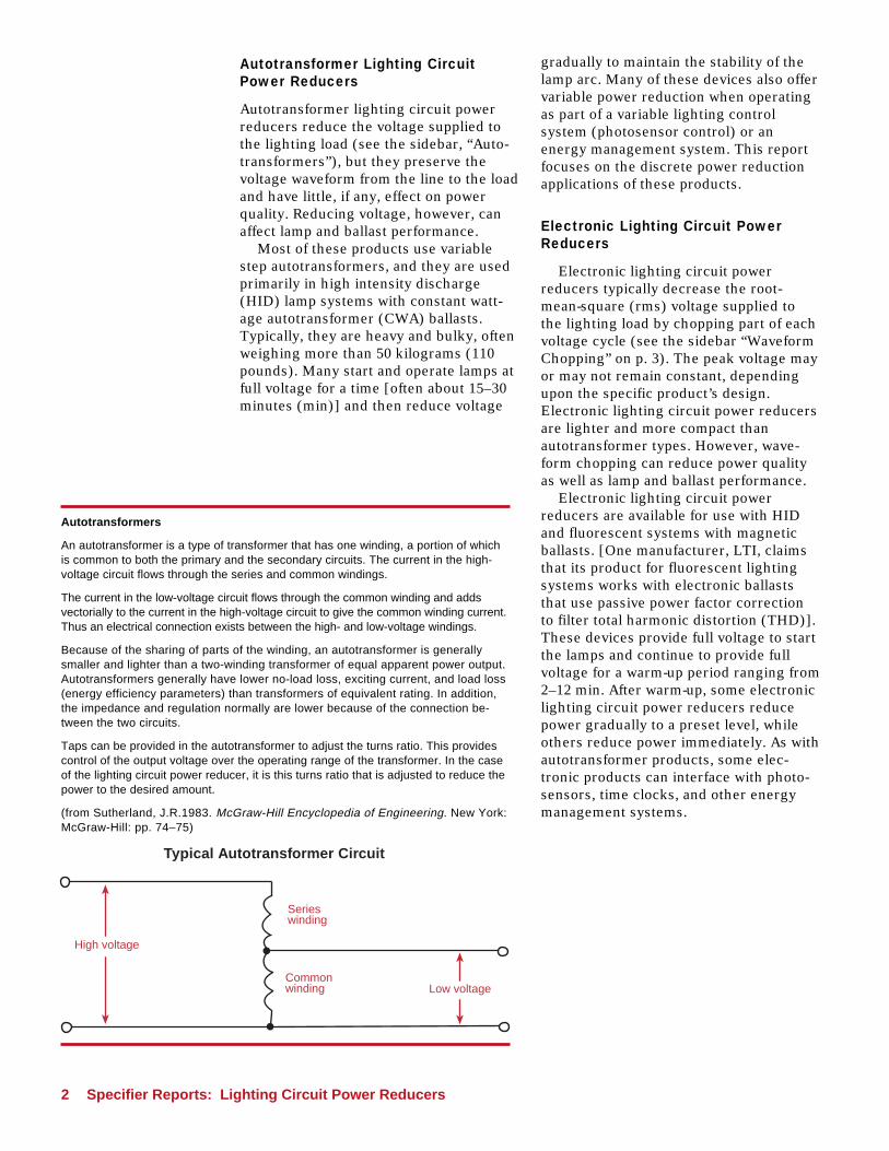
Autotransformers
An autotransformer is a type of transformer that has one winding, a portion of whichis common to both the primary and the secondary circuits. The current in the high-voltage circuit flows through the series and common windings.
The current in the low-voltage circuit flows through the common winding and addsvectorially to the current in the high-voltage circuit to give the common winding current.Thus an electrical connection exists between the high- and low-voltage windings.
Because of the sharing of parts of the winding, an autotransformer is generallysmaller and lighter than a two-winding transformer of equal apparent power output.Autotransformers generally have lower no-load loss, exciting current, and load loss(energy efficiency parameters) than transformers of equivalent rating. In addition,the impedance and regulation normally are lower because of the connection be-tween the two circuits.
Taps can be provided in the autotransformer to adjust the turns ratio. This providescontrol of the output voltage over the operating range of the transformer. In the caseof the lighting circuit power reducer, it is this turns ratio that is adjusted to reduce thepower to the desired amount.
(from Sutherland, J.R.1983. McGraw-Hill Encyclopedia of Engineering. New York:McGraw-Hill: pp. 74–75)
Typical Autotransformer Circuit
Serieswinding
Commonwinding
High voltage
Low voltage

Specifier Reports: Lighting Circuit Power Reducers 3
PerformanceCharacteristics
Power Reduction
Lighting circuit power reducers areinstalled primarily to obtain energysavings by reducing power to a lightingsystem. These products can reduce peakpower demand.
Most lighting circuit power reducershave adjustable settings of power reduc-tion, typically from 10–40%. Users canchoose one of the settings when a light-ing circuit power reducer is installed.Although the settings on many productscan be changed after installation, suchpractice usually does not occur becausethe products are installed at the electricpanel, which is generally not readilyaccessible to users.
Power reducer manufacturers typicallyrecommend reducing power by 25% formost applications. Therefore, NLPIPtested the products included in thisreport at the setting nearest this value.
Light Output & System Efficacy
Power reduction using lighting circuitpower reducers always reduces light outputand may affect system efficacy. Whilegreater power reduction is attractivebecause it means more energy savings, thereduced light output may be unacceptableto users and reduce visibility in the space.Many power reducer manufacturersrecommend cleaning and relamping lumi-naires at the time of installation of lightingcircuit power reducers to offset the imme-diate reduction in light output. However,this practice does not compensate for thereduced illuminance that results over timefrom luminaire dirt depreciation (LDD) andlamp lumen depreciation (LLD). Specifiersand users should consider the effect ofreducing light output on users beforeinstalling lighting circuit power reducers.
Power Quality
Power quality is the extent to which currentand voltage waves are in synchrony witheach other and conform to a sinusoidalshape. Poor power quality can negativelyaffect efficient and reliable operation of an
electrical system. Power factor and THD aremetrics for power quality.
Power factor. Power factor is defined asthe ratio of active power to apparentpower, which is the product of rmsvoltage and rms current; power factorranges from 0–1.0. A power factor of 1.0means that the voltage and currentwaveforms are identical and in phase.Power factor is reduced if there is a phaseshift between current and voltage or ifthere is a distortion of the sinusoidalwaveforms. Although low power factordevices do not necessarily use moreenergy than high power factor devices,they draw more current into the circuit.Larger supply equipment (includingconductors, transformers, and switchgear) is needed for low power factordevices to handle the added current,which is called reactive current. Resistivelosses in the wires caused by the reactivecurrent flow wastes energy in the electri-cal distribution system. Many utilitiespenalize customers whose facilities havepower factors less than 0.8 or 0.9 becauseutilities incur additional costs supplyingthe reactive current.
Waveform Chopping
Waveform chopping reduces the area under the curve rather than reducing theamplitude of the wave to reduce active power. Some lighting circuit powerreducers switch power off to produce energy savings, which produces a choppedvoltage waveform. However, because waveform chopping alters the shape of thewave, the process increases harmonic distortion.
Time
Voltage
Normalwaveform
Choppedwaveform

4 Specifier Reports: Lighting Circuit Power Reducers
Root-Mean-Square (rms)
The term root-mean-squarerefers to the procedureused to calculate theaverage value of a periodicwaveform, such as voltageor current. Mathematically,it is the square root of themean of the squaredvalues (volts or amps)taken over one completecycle. Thus, the term rmsvoltage expresses theaverage voltage.
4 Specifier Reports: Lighting Circuit Power Reducers
Definition and Standards for Harmonic Distortion
Higher values of THD indicate greater distortion. AmericanNational Standards Institute (ANSI) Standard C82.11 sets alimit of 32% current harmonic factor for electronic ballast sys-tems. The United States Department of Energy has proposedlimiting current THD to 20% on all lighting equipment. Manyutilities only include ballasts that have THD less than 20% intheir energy-efficiency programs.
Harmonics that are odd triple multiples of the fundamentalfrequency (3rd, 9th, 15th, ...) have the greatest potentialimpact on electrical systems because the current from theseharmonics flows on the neutral conductor and may overloadthis conductor. ANSI C82.11 also sets limits for odd triplesand other harmonics.
In this report, NLPIP uses the definition of the Institute ofElectrical and Electronic Engineers (IEEE 1035-1989) be-cause that is how ballast manufacturers typically report THD.This definition coincides with the definition of harmonic factorused by ANSI, Canadian Standards Association (CSA) andthe International Electrotechnical Commission (IEC).
THD =
whereI1 = fundamental current,I2 = current in second harmonic,I3 = current in third harmonic,I4 = current in fourth harmonic
ANSI, CSA, and IEC define THD as the ratio of the harmoniccontent to the rms value of the periodic current(all of the harmonic components including the fundamental),which is expressed as
THD =
I22 + I3
2 + I42 + ...
I1Î × 100
× 100I2
2 + I32 + I4
2 + ...
I1
2 +I2
2 + I3
2 + I4
2 + ...Î
Harmonic AnalysisHarmonic of waveform
Fundamental
3rd harmonic
5th harmonic
7th harmonic
9th harmonic
I1
I3
I5
I7
I9
From IAEEL newsletter 3-4/95, used with permission.

Specifier Reports: Lighting Circuit Power Reducers 5
Phase shift. Power factor is reduced ifthe current phase leads or lags behindthe voltage phase (see Figure 1). Mostfacilities have inductive loads such asmotors which cause lagging currents.
The reduction in power factor due tophase shift between current and voltagecan be easily corrected. Leading andlagging power factor devices on the samecircuit can partially or completely offseteach other, resulting in an overall im-provement in power factor. For mostfacilities with inductive loads such asmotors, external capacitor banks aretraditionally used to correct power factor,and reactive current only flows in the wiresin the facility’s devices and the capacitorsinstead of flowing back to the utility.
Harmonic distortion. Distortion of thesinusoidal current waveform, which can beexpressed as THD, reduces power factorand is difficult to correct. A distortedperiodic waveform can be represented as aharmonic series of sinusoidal waveformsof different amplitude and phase. Aharmonic series is a group of differentfrequency waveforms that are multiples ofthe lowest fundamental frequency. THD isa measure of the degree to which asinusoidal waveform is distorted byharmonics. It is defined mathematically asthe rms sum of the harmonic componentsexpressed as a percentage of the funda-mental component (see the sidebar“Definition and Standards for HarmonicDistortion” on p. 4). High levels of distor-tion in the distribution system can alsoharm electrical equipment.
Ballast Life
Ballast operating temperature affectsballast life. For fluorescent lamp ballastsoperating in luminaires at an ambienttemperature of 25o Celsius (C), Underwrit-ers Laboratories (UL) and the AmericanNational Standards Institute (ANSI) specifya maximum ballast case temperature of90oC. For ballast life ratings, ballastmanufacturers often specify a maximumballast case temperature lower than 90oC.Some manufacturers state as a rule ofthumb that every 10oC increase above therated ballast case temperature reducesthe ballast life by 50%. Higher operating
Figure 1. Schematic of a Lagging Current
temperatures also reduce the life ofballasts for HID lamps.
Because lighting circuit power reducersreduce active power, they should alsoreduce ballast operating temperaturesand therefore have the potential toextend ballast life. Accurately measuringballast case temperature requires longstabilization periods due to the thermalmass of ballasts and luminaires. NLPIPdid not measure ballast case temperaturefor this report.
Lamp Life
Fluorescent lamp life can be affected bylamp current crest factor (CCF) andelectrode starting temperature (seeNLPIP’s Guide to Selecting FrequentlySwitched T8 Lamp-Ballast Systems).
CCF is defined as the peak currentdivided by the rms current. The CCF of asinusoidal wave is 1.41. High CCF indi-cates that the current waveform has highpeaks that can reduce lamp life by in-creasing sputtering, which is the loss ofthe emissive material on the electrodes.Most lamp manufacturers void theirwarranties when CCF is greater than 1.70,which is also the limit adopted by ANSIC82.1-1985 (R1992).
High electrode temperatures can alsoreduce lamp life by increasing evaporationof the emissive coating on the lampelectrode. Low electrode temperatures canalso increase sputtering. Both temperature
-
+
Current
Voltage
Time
Amplitude

6 Specifier Reports: Lighting Circuit Power Reducers
conditions can also increase lamp-endblackening. Due to the difficulty of measur-ing electrode temperature directly, operat-ing electrode voltage is used as a relatedparameter in lighting standards. Forinstance, manufacturers assume that theelectrode operating voltages of rapid-startlamps is maintained between 2.5 and 4.0volts (V) when rating lamp life; thesevalues have also been adopted by ANSIC82.1-1985 (R1992).
No published reports document theeffect on lamp life of operating HID lampsat lower than the rated power. Therefore,NLPIP recommends that specifierscontact both the lamp and power reducermanufacturers to obtain more informationabout the effects of reduced poweroperation on HID lamps.
Human Perception
Flicker. Alternating current modulates thelight output of lamps, which can causeperceptible flicker. Flicker is a source ofworker complaints of eyestrain and head-ache. For lamps operated at a frequency of60 hertz (Hz), the light output oscillates120 times per second, which is generallyimperceptible. At high light levels, thehighest frequency the human eye candetect is approximately 75 Hz (Collins andHopkinson, 1957). But electronic compo-nents, such as lighting circuit powerreducers, used in the lighting circuit canintroduce lower frequencies of differentmodulation to the lamp current and causeperceptible flicker.
Color. Lamp color appearance or chroma-ticity coordinates may change when powerto a lighting system is reduced. The corre-lated color temperature of halophosphorfluorescent lamps does not vary substantiallyduring dimming from 100–20% light output.The color of triphosphor fluorescent lampsbecomes bluer below 50% light output(IESNA, 1993).
The color characteristics of HID lampsare greatly affected by changes in lamppower, with the most pronounced colorshift occurring when the lamp is operatingbelow 60% of the rated value. In LightingAnswers: HID Dimming, NLPIP reportedthat the correlated color temperature(CCT) of a 400-watt (W) coated metalhalide lamp shifts from 3850 kelvin (K) atfull power to 4310 K at 50% power. Previousresearch (Gibson, 1994) showed that thiscolor shift is more pronounced in clearmetal halide lamps than in coated lamps.
Illuminance change. After a warm-upperiod, power reducers reduce power whichreduces lamp light output. Manufacturerspreset the rate of change and may be able toadjust the settings according to customerspecifications. NLPIP recommends thatspecifiers ask manufacturers about adjust-ments that can be made to the rate ofilluminance change.
Sound. Magnetic ballasts and transformerssometimes produce a humming noise, whichis caused by vibrations in the laminatedmagnetic core. NLPIP researchers did nothear noise coming from the ballasts or powerreducer products during the testing, althoughNLPIP did not measure sound for this report.

Specifier Reports: Lighting Circuit Power Reducers 7
Performance Evaluations
NLPIP identified five manufacturers oflighting circuit power reducers throughequipment directories and advertisementsand invited them to participate in thisproject. All five agreed to participate.
Some manufacturers sell a series ofmodels for different line voltages, circuitcurrents, phases (single or three phase),and lighting control strategies. Otherscustomize a product to meet customerrequirements. Table 1 on p. 14 lists thelighting circuit power reducers availablefrom these manufacturers.
NLPIP Testing Procedure
NLPIP tested lighting circuit powerreducers using the fluorescent lightingsystems in the mechanical room andthree adjacent small rooms at the IowaEnergy Center’s Energy Resource Stationin Ankeny, Iowa. Figure 2 is a reflectedceiling plan of these spaces. The lumi-naires in these rooms are wired to asingle circuit breaker. The rooms havewhite walls and ceilings and light grayconcrete floors. Light output was mea-sured in the mechanical room. Photomet-
ric measurements were also taken in themechanical room, which is approximately60 × 32 ft [18.3 × 9.7 meters (m)]. Electri-cal and thermal parameters were mea-sured in the electrical room, which isapproximately 10 × 11 ft (3.0 × 3.3 m) andcontains all the electrical panels for thebuilding. During the testing period, theinput voltage to the entire circuit was at280 ± 2 V, and the room temperature wasat 22.4 ± 0.2oC. The lighting system (withhigh power factor ballasts) had a powerfactor of 0.99 and leading voltage.
A total of 36 fluorescent lamp luminaireswere connected to the circuit breaker.These were two-lamp luminaires withwhite reflectors but no lenses or enclo-sures (Thomas Day-Brite IA240–120).The lamps were rapid-start 40-W T12lamps (Sylvania F40/D41 RS), with a CCTof 4100 K and a color rendering index(CRI) of 70. Energy-saving magneticballasts (MagneTek Universal 443-L-SLH-TC-P) for two F40T12 lamps operated thelamps at 277 V and 60 Hz. All the lamps,ballasts, and fixtures were newly pur-chased and installed at the Iowa EnergyCenter specifically for this testing, replac-ing the existing electronic ballasted T8lamp system. The lamps and ballasts wereseasoned for 120 hours prior to testing.
Figure 2. Testing Locations
Spot #4
Spot #5
Spot #2
Spot #3 Spot #1Mechanical Room
60 ́× 32´StorageRoom
Equipment Room
Electrical Room10 ́× 11´
x
x
x
x x
Spot #4
Spot #5
Spot #2
Spot #3 Spot #1Mechanical room60 ́× 32´
Storageroom
Equipment room
Electrical room10 ́× 11´
Electricalpanel

8 Specifier Reports: Lighting Circuit Power Reducers
NLPIP tested three lighting circuitpower reducers, one each from EnergyAutomation System, Inc.; ESI LightingControls; and LTI International, Inc.Although the product from ESI LightingControls operates HID systems, NLPIPtested it for this report because the manu-facturer promotes it for use with fluores-cent systems with magnetic ballasts.
The ESI product is an autotransformerlighting circuit power reducer, and theEASI and the LTI products are electroniclighting circuit power reducers. NLPIPalso obtained a fourth product from itsmanufacturer, EMAC, but could not get itto work properly, even after consultingwith the manufacturer. Since the timeframe for testing was limited, EMAC couldnot replace the product in time.
One manufacturer, LTI, would onlyparticipate if a representative could bepresent during the installation of theirproduct. NLPIP agreed to this request butdid not allow any manufacturer to bepresent during testing.
Each lighting circuit power reducer wasinstalled between the circuit breaker andthe lighting load, according to the manu-facturers’ instructions. A relay allowedNLPIP to bypass the power reducer.
A power analyzer (Xitron model 2503H-3CH+INT-A) was used to measure electri-cal parameters (voltage, current, activepower, power factor, current crest factor,current THD, and frequency). The power
analyzer interfaced through a GeneralPurpose Interface Bus (GPIB) board to apersonal computer with data acquisitionsoftware (LabVIEW). Electrical param-eters were measured at the input to thepower reducer, between the power re-ducer and the ballasts, and between theballast and the lamps. Measurements weretaken with the power reducers in opera-tion and bypassed. A Pearson current
The ESI Power Reducer,Ready for Testing
Figure 3. Schematic Diagram of Testing Apparatus forPanel-level Power Reducers
Ballast
Lightingcircuitpowerreducer
Thermometer
Lamp
Lamp
Printer
Power analyzer
GPIB
Computer
Circuit breaker
Illuminancemeter
Chromaticitymeter
ProbeProbe
Probe
Relaybypassswitch
Relaybypassswitch

Specifier Reports: Lighting Circuit Power Reducers 9
transformer was used between the ballastand the lamps for measurement of lampcurrent. NLPIP also measured lamp arcvoltage and lamp electrode voltage at thispoint. A digital thermometer (CooperSH66A) was used to measure the tem-peratures of the ballast case and room.None of the ballast case temperaturesexceeded 50oC.
NLPIP measured illuminance at fivespots on the floor of the mechanical room,using an illuminance meter (United Detec-tor, Model #351). Each of the spots wasdirectly beneath one of the luminaires.
NLPIP measured color shift by placinga diffuse white plate at spot #5 (see Figure 2on p. 7) and measured the chromaticityvalues of the plate for each test conditionusing a Minolta CS 100 meter.
NLPIP tested each product at itsclosest setting to 25% power reduction.When a lighting circuit power reducerwas first installed, the switches were setto bypass the power reducer. After a 30minute warm-up, baseline measurementswere taken. The switches were then setto include the power reducer in thecircuit. Data were collected 30 minutesafter the power reducer began operating.
Results
Tables 2 and 3 show that the productsNLPIP tested for fluorescent lightingsystems reduced input voltage by 21.0,22.8, and 24.1% and illuminances by 31,21, and 26% respectively. For HIDlighting systems, independent testreports provided to NLPIP by manufac-turers reported light loss percentagesranging from 26–39% with lighting circuitpower reducers.
LTI Power Reducer Used in Testing
NLPIP describes the impact of lightingcircuit power reducers on the lightingsystem by the power reducer efficiencyfactor (PREF), which is the ratio of thelighting system efficacy with powerreducers installed to the system efficacywithout power reducers.
A PREF greater than 1 indicates thatthe lighting circuit power reducer in-creases the efficacy of the lighting system,while a PREF less than 1 indicates that theproduct reduces the system efficacy.NLPIP calculated the PREF to be 1.02 forthe LTI product, 0.97 for the ESI product,and 0.87 for the EASI product.
Of the three lighting circuit powerreducers tested by NLPIP, the EASIlighting circuit power reducer caused CCFto rise to 1.90, in excess of the ANSI limit;both the LTI and the ESI products heldCCF below 1.70. However, none of thepower reducers maintained operatinglamp electrode voltage above 2.5 V.
The ESI autotransformer power re-ducer preserves the voltage waveformfrom the line to the load and conse-quently does not significantly increasecurrent THD to the circuit (see Table 4).However, the electronic lighting circuitpower reducers chop part of each voltagecycle, which can produce harmonicdistortions. NLPIP found that the EASIelectronic lighting circuit power reducerhad current THD as high as 45%, which isabove the ANSI limit. The sum of its oddtriple harmonics was also 45%, while theANSI limit is 30%. LTI claims that thedesign of its product reduces harmonicdistortion from its power reducer andprovides a leading current. None of theharmonics produced by the LTI powerreducer exceeded ANSI limits.

10 Specifier Reports: Lighting Circuit Power Reducers
NLPIP found that the LTI and the ESIpower reducers reduced the illuminance atthe rate of about 0.3–0.4% per second, whichwas unnoticeable to the NLPIP researchers.However, the EASI product reduced theilluminance almost instantly; this changewas noticeable.
NLPIP observed no flicker with either theLTI or the ESI lighting circuit powerreducers tested at either full or 25% reducedpower but observed that the EASI productcaused flicker at both settings. NLPIPdetermined that the EASI product intro-duced a new frequency to the lighting loadcurrent. Ranging from 70–90 Hz, this newcurrent frequency had an amplitude up to50% of the amplitude at 60 Hz of the funda-mental frequency. When the power levelwas reduced, the combination of the funda-mental frequency with this additionalfrequency resulted in a lamp currentmodulation frequency between 10 and 30Hz. This, in turn, produced a 20–60 Hz lightoutput oscillation, which is perceptible.
The F40T12/RE741 fluorescent lamps,which were specially installed at the Iowa
Energy Center where the NLPIP testingtook place, combine a halophosphor coatingwith a triphosphor coating. NLPIP found nochange in chromaticity for any of the threeproducts evaluated when the productsreduced system power by 25%.
Alternative Technologies
Alternatives to installing lighting circuitpower reducers for fluorescent lightingsystems include energy-saving fluores-cent lamps, specular reflectors, T8 lampswith electronic ballasts, dimming elec-tronic ballasts, and power reducers thatare hardwired between the ballast and thelamps. Some of these technologies can beused in combination with lighting circuitpower reducers. Few alternatives exist forlighting circuit power reducers for HIDlighting systems. Other alternatives, suchas time clocks or occupancy sensors,reduce the operating time of lamp andballasts, not their active power, and arenot described in this section.
The EASI Power Reducer1234567890123456789012345678901212345678901234567890123456789012123456123456789012345678901234567890121234567890123456789012345678901212345612345678901234567890123456789012123456789012345678901234567890121234561234567890123456789012345678901212345678901234567890123456789012123456123456789012345678901234567890121234567890123456789012345678901212345612345678901234567890123456789012123456789012345678901234567890121234561234567890123456789012345678901212345678901234567890123456789012123456123456789012345678901234567890121234567890123456789012345678901212345612345678901234567890123456789012123456789012345678901234567890121234561234567890123456789012345678901212345678901234567890123456789012123456123456789012345678901234567890121234567890123456789012345678901212345612345678901234567890123456789012123456789012345678901234567890121234561234567890123456789012345678901212345678901234567890123456789012123456123456789012345678901234567890121234567890123456789012345678901212345612345678901234567890123456789012123456789012345678901234567890121234561234567890123456789012345678901212345678901234567890123456789012123456123456789012345678901234567890121234567890123456789012345678901212345612345678901234567890123456789012123456789012345678901234567890121234561234567890123456789012345678901212345678901234567890123456789012123456123456789012345678901234567890121234567890123456789012345678901212345612345678901234567890123456789012123456789012345678901234567890121234561234567890123456789012345678901212345678901234567890123456789012123456123456789012345678901234567890121234567890123456789012345678901212345612345678901234567890123456789012123456789012345678901234567890121234561234567890123456789012345678901212345678901234567890123456789012123456123456789012345678901234567890121234567890123456789012345678901212345612345678901234567890123456789012123456789012345678901234567890121234561234567890123456789012345678901212345678901234567890123456789012123456123456789012345678901234567890121234567890123456789012345678901212345612345678901234567890123456789012123456789012345678901234567890121234561234567890123456789012345678901212345678901234567890123456789012123456123456789012345678901234567890121234567890123456789012345678901212345612345678901234567890123456789012123456789012345678901234567890121234561234567890123456789012345678901212345678901234567890123456789012123456123456789012345678901234567890121234567890123456789012345678901212345612345678901234567890123456789012123456789012345678901234567890121234561234567890123456789012345678901212345678901234567890123456789012123456123456789012345678901234567890121234567890123456789012345678901212345612345678901234567890123456789012123456789012345678901234567890121234561234567890123456789012345678901212345678901234567890123456789012123456123456789012345678901234567890121234567890123456789012345678901212345612345678901234567890123456789012123456789012345678901234567890121234561234567890123456789012345678901212345678901234567890123456789012123456123456789012345678901234567890121234567890123456789012345678901212345612345678901234567890123456789012123456789012345678901234567890121234561234567890123456789012345678901212345678901234567890123456789012123456123456789012345678901234567890121234567890123456789012345678901212345612345678901234567890123456789012123456789012345678901234567890121234561234567890123456789012345678901212345678901234567890123456789012123456123456789012345678901234567890121234567890123456789012345678901212345612345678901234567890123456789012123456789012345678901234567890121234561234567890123456789012345678901212345678901234567890123456789012123456

Specifier Reports: Lighting Circuit Power Reducers 11
Energy-Saving Lamps
Energy-saving lamps reduce power de-mand, typically by 15% for rapid-start lampsand 20% for instant-start lamps. Reducedlight output is proportional to reducedpower. The installation of energy-savinglamps is an easy retrofit that requires norewiring. Although energy-saving lamps arecompatible with most ballasts, they mayreduce the ballast life of some magneticballasts due to increased heat from ballastwinding losses. Another disadvantage tothis technology is that energy-saving lampscan be easily replaced at any time by non-energy-saving lamps.
Delamping with Specular Reflectors
The most common application of specularreflectors is in 2 × 4-ft four-lamp fluores-cent luminaires. Usually, the installerremoves two of the existing lamps, discon-nects one ballast, repositions the socketsfor the remaining two lamps, and theninserts a specular reflector, which hasbeen designed to reflect and redirect lightoutput from the lamps. Typically 40–50%power reductions can be achieved with35–45% decreased light output. NLPIP’sSpecifier Reports: Specular Reflectors (1992)contains more details on this technology.Installing specular reflectors in conjunc-tion with delamping may only be anacceptable option in areas where theexisting illuminance is high. Buildingoccupants may react negatively since thisapproach affects light distribution and maycause non-uniform illuminance.
T8 Lamps and Electronic Ballasts
Replacing T12 lamps and magnetic ballastswith T8 lamps and electronic ballasts is themost common efficiency upgrade forfluorescent lighting systems. NLPIP’sLighting Answers: T8 Fluorescent Lamps(1993) and Specifier Reports: ElectronicBallasts (1994), with supplements in 1995,1996, and 1997 address these systems.
T8 lamps achieve both high colorrendering and high efficacy by employing
rare-earth phosphors. Electronic ballastsfurther improve the efficacy of T8 lampsby 10–15% by operating them at muchhigher frequencies (typically above 20 kHz)than the standard 60 Hz at which mag-netic ballasts operate lamps. Thus, afluorescent lighting system using high-frequency electronic ballasts requireslower power to produce the same amountof light as a 60 Hz magnetic ballastsystem. Many electronic ballasts offerother advantages, such as reduced flickerand less heat, weight, and noise. How-ever, installation cost is high because ofthe labor needed to replace the ballast ineach luminaire.
Most commercially available electronicballasts operate T8 lamps at a slightlyreduced light output level while demand-ing significantly reduced power comparedto magnetic ballasts. However, the lightoutput of a luminaire using T8 lamps andelectronic ballasts is not necessarily lessthan that of a luminaire using T12 lampsand magnetic ballasts, due to thermal andoptical effects within the luminaire. T8lamps also exhibit less lumen deprecia-tion than T12 lamps.
Dimming Electronic Ballasts
Dimming electronic ballasts provide allthe benefits offered by electronic ballastsplus the ability to vary light output, eitherthrough manual or automatic control.NLPIP’s Specifier Reports: DimmingElectronic Ballasts (1995) provides detailson these products.
Dimming electronic ballasts thatreduce light output to 20% of maximumare widely available and are suitable formost energy-saving applications. They canbe controlled by occupancy sensors todim lamps when no motion is detected ina space, by photosensors where daylightis available, or by other energy manage-ment systems to dim lamps during peakdemand hours. However, the installationcost for this retrofit is high because of thecost of the ballasts and the associatedcontrol products and the labor for replac-ing ballasts in individual fixtures.
12 Specifier Reports: Lighting Circuit Power Reducers
Power Reducers Hardwired Betweenthe Ballast and the Lamps
Individual power reducers are available tocontrol luminaires. Both power and lightoutput are reduced by a fixed amount,although the power reduction is usuallygreater than the light output reduction. Thephotometric distribution of the luminaire isnot affected by the power reduction.
Most power reducers require somerewiring and mounting, so the installationcosts are similar to those for electronicballasts. Nearly all the power reducerspreviously tested by NLPIP reduced powerfactor and increased THD (see SpecifierReports: Power Reducers, 1992). Most powerreducer manufacturers recommend thattheir products be used only with certaintypes of fluorescent lamp-ballast systems.
Further Information
American National Standards Institute,1992. Ballasts for fluorescent lamps speci-fications, ANSI C82.1-1985(R1992). NewYork, NY: American NationalStandards Institute.
American National Standards Institute,1993. High-frequency fluorescent lampballasts, ANSI C82.11-1993. New York, NY:American National Standards Institute.
Collins, J.B. and Hopkinson, R.G., Inter-mittent light stimulation and flicker sensa-tion. Ergonomics, 1, 61, 1957.
Gibson, R.G. 1994. Dimming of metalhalide lamps. Journal of the IlluminatingEngineering Society. 23(2):19–25.
Illuminating Engineering Society of NorthAmerica. 1993. Lighting Handbook: Refer-ence & Application. 8th. ed. M.S. Rea, ed.New York, NY: Illuminating EngineeringSociety of North America.
Underwriters Laboratories, 1992. Standardfor safety: Fluorescent lamp ballasts,UL-935. Northbrook, IL: UnderwritersLaboratories.

Specifier Reports: Lighting Circuit Power Reducers 13
Data Table Termsand Definitions
The following data tables present informa-tion obtained by NLPIP during producttesting. Most of the performance character-istics listed in these tables are discussedpreviously in this report, but the columnheadings are defined.
Active power. System input in watts.
Apparent power. The product of rmsvoltage and rms current.
Average illuminance. The average of thefive illuminance measurements takenwithin the space controlled by the circuitlevel power reducer.
CCF. Defined as the peak current dividedby the rms current of a lamp. CCF rangesfrom one to infinity.
Current THD. A measure of the degree towhich the current waveform is distorted,expressed as a percentage.
Harmonics. Distortions of a periodicsinusoidal waveform represented as aharmonic series of sinusoidal waveforms ofdifferent amplitude and phase. A harmonicseries is a group of different frequencywaveforms that are multiples of the lowestor fundamental frequency.
Lamp electrode voltage. Voltage to theelectrodes to operate the lamp.
Light loss (%). The reduced light outputcaused by the circuit level power reducerexpressed as a percentage of the lightoutput without the circuit level powerreducer. (Full system output minus re-duced output with a lighting circuit powerreducer divided by the full system outputtimes 100.)
Power factor. The ratio of active power toapparent power.
Power reduction. The amount by whichactive power to the lighting system isreduced by the lighting circuit powerreducer.
Power reduction efficiency factor. Ameasure of the efficiency of a powerreducer, representing the reduced lightoutput in percent from a lighting circuitpower reducer divided by the reducedactive power in percent from a lightingcircuit power reducer.
rms current. Root-mean-square current,an expression that quantifies the magni-tude of a current that varies with time (asin ac circuits). Rms current is calculatedas the square root of the mean of thesquared values of current over one com-plete cycle. Rms current delivers the samepower to a resistive load as an equivalentsteady dc current.

14 Specifier Reports: Lighting Circuit Power Reducers
Lighting Circuit Power Reducers for Single-Phase HID Lighting Systems (MH, HPS, and Mercury Vapor)with CWA Ballasts
Table 1. Manufacturer-Supplied Information
a Only for passive power correction electronic ballasts.b Higher voltage models available.c Four-circuit models available.d Dual and three-circuit models available.e Also works with some fluorescent lighting systems.f Three-phase models available.g For 400-W lamps or greater.h For 175-W or greater metal halide and mercury vapor lamps and 250-W or greater high pressure sodium lamps
Lighting Circuit Power Reducers for Fluorescent Lighting Systems
a Only for passive power correction electronic ballasts.
tsallaBcitengaM tsallaBcinortcelE
)V(tiucriC 021 802 042 772 021 802 042 772
)A(tiucriC 21 61 21 61 21 61 21 61 21 61 21 61 21 61 21 61
rerutcafunaM
CAME5997-136-008 • • • • • •
noitamotuAygrenE.cnI,metsyS0527-228-516
• • • •
SE slortnoCgnithgiLI7103-367-614 • • • • • • • •
.cnI,lanoitanretnIITL5155-485-008 • • • •a
)V(tiucriC 021 802 042 772
)A(tiucriC 21 61 42 23 54 58 21 61 23 21 61 23 58 21 61 42 23 58
rerutcafunaM
CAME e,d,c,b
5997-136-008 • • • • • •
noitamotuAygrenE.cnI,metsyS f
0527-228-516•g • •g •g • •g •
SE gnithgiLIslortnoC b, e
7103-367-614• • • •
.cnI,lanoitanretnIITL h
5155-485-008 • • • • • • • •
irtcelErenraW c c,b ,e, f
0054-585-068 • • • • • • • • •

Specifier Reports: Lighting Circuit Power Reducers 15
Table 2. NLPIP-Measured Data: Circuit Lighting Power Reducer Performance Measured at the ElectricalPanel and at the Luminaire
Table 4. NLPIP-Measured Data: Lighting Circuit Power Quality
NA = not applicablea ANSI standard for maximum CCF is 1.70.b ANSI standard for rapid-start lamps is 2.5–4.0.
NA = not applicablea Measurements were taken with power reducer bypassed.b For comparison only. ANSI standard applies to the ballast and not to the entire circuit.
ecnamrofrePmetsyS ecnamrofrePerianimuL
rerutcafunaM emaNedarTgolataCrebmuN
tupnIsmr
egatloV)V(
tupnIsmr
tnerruC)A(
tnerappArewoP)AVk(
evitcArewoP
)Wk(
tupnIsmr
egatloV)V(
tupnIsmr
tnerruC)Am(
tnerappArewoP
)AV(
evitcArewoP
)W( FCC a
pmaLedortcelE
egatloV b
)Vsmr(
enilesaB AN AN 8.082 0.21 4.3 3.3 0.082 033 4.29 5.19 36.1 1.3
ISAECLF
tnecseroulFrellortnoCthgiL
VI-CLF 0.082 1.41 9.3 6.2 3.722 583 4.78 4.07 09.1 4.2
ISE AN SC21A 9.972 82.9 6.2 5.2 1.112 623 8.86 0.76 55.1 2.2
ITL ttawartlU A6UBL 8.182 7.11 3.3 6.2 0.022 223 9.07 8.96 54.1 3.2
Table 3. NLPIP-Measured Data: Power Reduction and Light Loss
rerutcafunaM emaNedarT rebmuNgolataC
rewoPnoitcudeR
)%(
thgiLssoL)%(
noitcudeRrewoPycneiciffE
rotcaF
enilesaB AN AN 0 0 1
ISAE rellortnoCthgiLtnecseroulFCLF VI-CLF 0.12 13 78.0
ISE AN SC21A 1.42 62 79.0
ITL ttawartlU A6UBL 8.22 12 0.1
NA = not applicable
scinomraH
rerutcafunaM emaNedarTgolataCrebmuN rotcaFrewoP
tnerruCDHT)%(
dnoceS)%(
drihT)%(
htniN)%(
htneetfiF)%(
enilesaB a AN AN dael989.0 4.41 3.0 9.9 6.1 4.0
ISAECLF
tnecseroulFrellortnoCthgiL
VI-CLF gal076.0 2.54 1.2 6.44 0.2 4.0
ISE AN SC21A gal479.0 5.81 2.0 7.71 1.1 3.0
ITL ttawartlU A6UBL dael977.0 3.71 8.1 7.31 3.1 2.0
ISNAdradnatS b AN AN AN 23< 5< 03< 03< 7<

16 Specifier Reports: Lighting Circuit Power Reducers
For publications orderinginformation, contact:
Lighting Research CenterRensselaer Polytechnic InstituteTroy, NY 12180-3590Phone: (518) 276-8716Fax: (518) 276-2999Internet e-mail: [email protected] Wide Web:
http://www.lrc.rpi.edu
Specifier ReportsLighting Circuit Power Reducers
Volume 6, Number 2September, 1998
Principal Investigator: Yunjian HeTechnical Editor: Katherine MillerProgram Director: Robert Davis, Russ LeslieProduction Manager: James GrossProduction and Graphics: Susan Mahar
© 1998 Rensselaer Polytechnic Institute.All Rights Reserved.
The production of this report involvedimportant contributions from many staffmembers at the Light Research Center(LRC). A. Bierman helped conduct thetesting. W. Chen and C. O’Rourke providedassistance and suggestions throughout theproject. Other LRC project team memberswho contributed include J. Ceterski,K. Heslin, Y. Ji, and M. Rea.
The Iowa Energy Center offered significantcontributions in providing the testing site,and installing the lighting system incompliance with the requirements of theproducts, and assisting with the testingprocess. Special thanks to C. Klaassen,J. Webster, N. Olson, and F. Barwig.
Technical reviews were provided byR. Hammer, R. Smith, W. VonNeida, andD. Wood. Reviewers are listed to acknowl-edge their contributions to the finalpublication. Their approval or endorsementof this report is not necessarily implied.
No portion of this publication or theinformation contained herein may beduplicated or excerpted in any way in otherpublications, databases, or any othermedium without express written permission
from Rensselaer Polytechnic Institute. Makingcopies of all or part of this publication for anypurpose other than for undistributed personaluse is a violation of United States copyrightlaws. It is against the law to inaccuratelypresent information extracted from SpecifierReports for product publicity purposes.
The products described herein have not beentested for safety. The Lighting Research Centerand Rensselaer Polytechnic Institute make norepresentations whatsoever with regard tosafety of products, in whatever form orcombination used, and the results of testing setforth for your information cannot be regardedas a representation that the products are or arenot safe to use in any specific situation, or thatthe particular product you purchase willconform to the results found in this report.
The National Lighting Product Information Program
Publications:Guide to Performance Evaluation of Efficient Lighting Products, 1991Guide to Fluorescent Lamp-Ballast Compatibility, 1996Guide to Specifying High-Frequency Electronic Ballasts, 1996Guide to Specifying Frequently Switched Electronic Ballasts, 1998Specifier Reports
Power Reducers, 1992; Specular Reflectors, 1992;Parking Lot Luminaires, 1993; Screwbase Compact Fluorescent LampProducts, 1993; Cathode-Disconnect Ballasts, 1993; Exit Signs, 1994;Electronic Ballasts, 1994; Reflector Lamps, 1994; CFL Downlights, 1995;Dimming Electronic Ballasts, 1995; HID Accent Lighting Systems, 1996;Occupancy Sensors, 1997; Photosensors, 1998; Dimming Electronic Ballasts, 1998
Specifier Reports SupplementsScrewbase Compact Fluorescent Lamp Products, 1994, 1995; Exit Signs, 1995, 1998;Electronic Ballasts, 1995, 1996, 1997
Lighting AnswersT8 Fluorescent Lamps, 1993; Multilayer Polarizer Panels, 1993; Task Lighting forOffices, 1994; Dimming Systems for High-Intensity Discharge Lamps, 1994; Electro-magnetic Interference Involving Fluorescent Lighting Systems, 1995; Power Quality,1995; Thermal Effects in 2'×4' Fluorescent Lighting Systems, 1995; T10 and T9Fluorescent Lamps, 1995; T5FT Lamps and Ballasts, 1996; Controlling Lightingwith Building Automation Systems, 1997
The National Lighting ProductInformation Program (NLPIP) wasestablished in 1990 and is adminis-tered by the Lighting Research Centerat Rensselaer Polytechnic Institute.The Lighting Research Center is anonprofit educational and researchorganization dedicated to the advance-ment of lighting knowledge.
NLPIP’s mission is to rapidly providethe best information available onenergy-efficient lighting products.NLPIP strives to provide complete,current, and valuable manufacturer-specific performance data in usefulformats to guide lighting decisions.Priority is given to information notavailable now or not easily accessiblefrom other sources.
The National Lighting ProductInformation Program tests lightingproducts according to acceptedindustry procedures. If procedures arenot available or applicable, NLPIPdevelops interim tests, focusing onthose performance issues that areimportant to the lighting specifier andend user. The program does notaccept funding from manufacturers.
ISSN 1067-245150%
TOTAL RECOVERED FIBER15% POST-CONSUMER FIBER
Lighting Circuit Power Reducers
Volume 6 Number 2 Supplement 1 September 2005
Introduction This supplement to Specifier Reports: Lighting Circuit Power Reducers presentsmanufacturer-supplied and NLPIP-measured data on a product not tested inthe original document. For background information on this technology, consultthe original report at www.lrc.rpi.edu/programs/NLPIP/publications.asp.
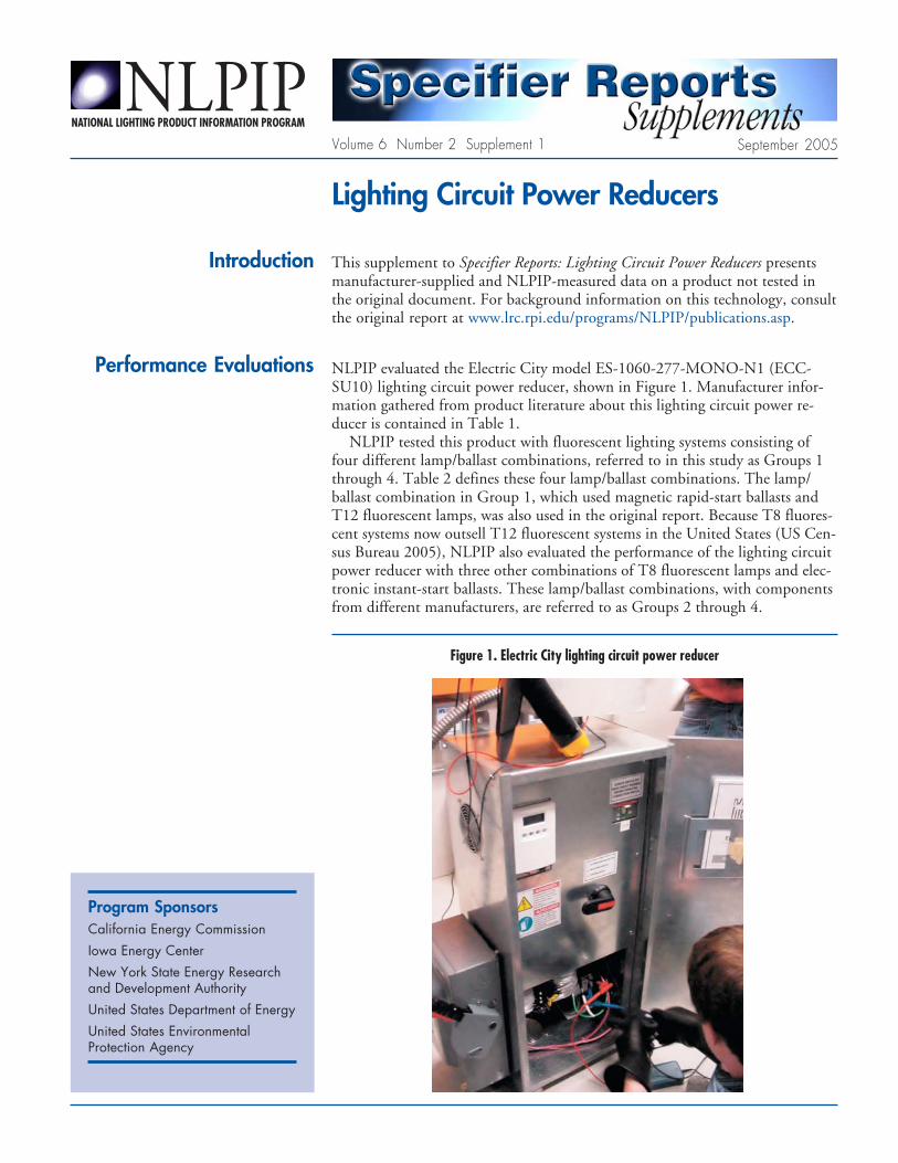
Performance Evaluations NLPIP evaluated the Electric City model ES-1060-277-MONO-N1 (ECC-SU10) lighting circuit power reducer, shown in Figure 1. Manufacturer infor-mation gathered from product literature about this lighting circuit power re-ducer is contained in Table 1.
NLPIP tested this product with fluorescent lighting systems consisting offour different lamp/ballast combinations, referred to in this study as Groups 1through 4. Table 2 defines these four lamp/ballast combinations. The lamp/ballast combination in Group 1, which used magnetic rapid-start ballasts andT12 fluorescent lamps, was also used in the original report. Because T8 fluores-cent systems now outsell T12 fluorescent systems in the United States (US Cen-sus Bureau 2005), NLPIP also evaluated the performance of the lighting circuitpower reducer with three other combinations of T8 fluorescent lamps and elec-tronic instant-start ballasts. These lamp/ballast combinations, with componentsfrom different manufacturers, are referred to as Groups 2 through 4.
Program SponsorsCalifornia Energy Commission
Iowa Energy CenterNew York State Energy Researchand Development Authority
United States Department of EnergyUnited States EnvironmentalProtection Agency
Figure 1. Electric City lighting circuit power reducer

2 Specifier Reports Supplements: Lighting Circuit Power Reducers
NLPIP Testing Procedure
As in the original study, NLPIP tested the Electric City lighting circuit powerreducer on the fluorescent lighting systems already installed in the utility roomof the Iowa Energy Center’s Energy Resource Station in Ankeny, Iowa. NLPIPused the same testing space again, which is shown on p. 7 of the original report.The testing occurred from August 9, 2004 to August 11, 2004.
Electric City provides lighting circuit power reducers with a variety of cur-rent-carrying capacities (shown in Table 1), as well as single-phase and three-phase options. The lighting circuit power reducer tested in this supplement hada current capacity of 60 amps (A); in the original report, the products had a 20A capacity. To evaluate this larger capacity, NLPIP loaded the lighting circuitpower reducer with other fluorescent lighting loads from within the building.For purposes of this study, NLPIP adjusted the voltage setting by a keypadlocated on the front panel of the lighting circuit power reducer. While ElectricCity also provides software to control the lighting circuit power reducer from aremote location, NLPIP did not evaluate this software.
Prior to testing, NLPIP seasoned all of the T8 fluorescent lamps for 100hours (h), as specified by the Illuminating Engineering Society of NorthAmerica (IESNA) in the IESNA Guide to Lamp Seasoning (1999). NLPIP usedthe standard 3-hours-on, 20-minutes-off cycle. Seasoning occurred in theNLPIP fluorescent lamp testing laboratory in Watervliet, New York. The T12fluorescent lamps were installed in the test site’s lighting system and seasonedthere to at least 100 h before testing.
Electricians from the Energy Resource Station installed the lighting circuitpower reducer, according to manufacturer’s instructions, in the electrical circuitbefore the lighting panel (see Figure 2). Representatives from Electric City com-missioned the lighting circuit power reducer and verified that it was installedproperly. However, they were not present for testing.
Before testing each group, NLPIP took baseline measurements with the light-ing circuit power reducer out of the circuit. The lighting circuit power reducerwas then removed from the system by opening the two isolation switches andclosing the bypass switch (see Figure 2). After operating the system for a 30-minute (min) warm-up period, which allowed the lamps and ballasts to stabi-lize, NLPIP took baseline measurements of voltage, current, temperature, andilluminance. They compared these measurements to each group’s performancedata to evaluate power and light output reduction for the system.
Figure 2. Lighting circuit power reducer schematic
Specifier Reports Supplements: Lighting Circuit Power Reducers 3
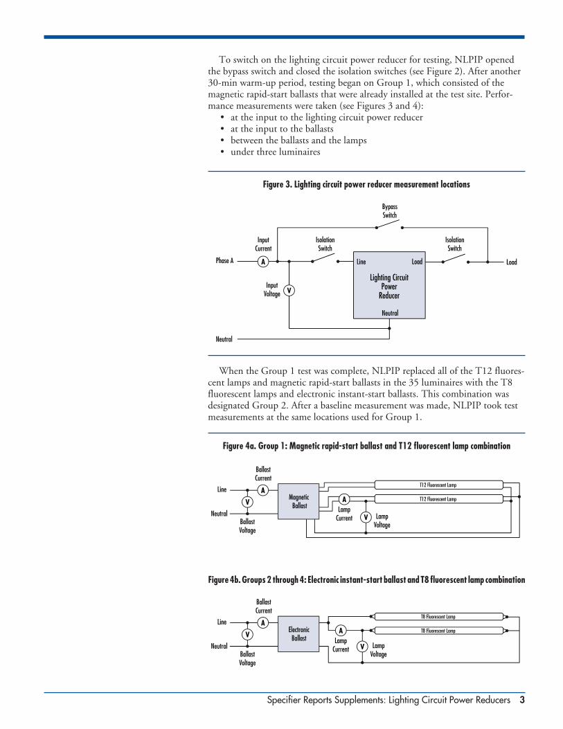
To switch on the lighting circuit power reducer for testing, NLPIP openedthe bypass switch and closed the isolation switches (see Figure 2). After another30-min warm-up period, testing began on Group 1, which consisted of themagnetic rapid-start ballasts that were already installed at the test site. Perfor-mance measurements were taken (see Figures 3 and 4):
• at the input to the lighting circuit power reducer• at the input to the ballasts• between the ballasts and the lamps• under three luminaires
Figure 3. Lighting circuit power reducer measurement locations
When the Group 1 test was complete, NLPIP replaced all of the T12 fluores-cent lamps and magnetic rapid-start ballasts in the 35 luminaires with the T8fluorescent lamps and electronic instant-start ballasts. This combination wasdesignated Group 2. After a baseline measurement was made, NLPIP took testmeasurements at the same locations used for Group 1.
Figure 4a. Group 1: Magnetic rapid-start ballast and T12 fluorescent lamp combination
Figure 4b. Groups 2 through 4: Electronic instant-start ballast and T8 fluorescent lamp combination

4 Specifier Reports Supplements: Lighting Circuit Power Reducers
Because Groups 3 and 4 also used T8 fluorescent lamps and electronic in-stant-start ballasts, NLPIP changed the individual lamp/ballast combinationsfor those groups only at the three measured luminaires. Baseline and test mea-surements for Groups 3 and 4 were made in the same manner as for the othergroups.
Prior to testing, Electric City provided settings for using the lighting circuitpower reducer with T8 fluorescent lamps. These individual settings were basedon minimal lamp current values for the different lamp models. To achieve this,NLPIP adjusted the lighting circuit power reducer voltage setting to meet thelamp current requirement for each manufacturer’s lamp. No recommendedsetting was provided for the T12 fluorescent lamp, so NLPIP tested it at thesetting most closely corresponding to a 25% power reduction, the amount ofthe power reduction tested in the original study.
An oscilloscope (LeCroy WaveRunner, model 6050) was used to measure thefollowing electrical parameters:
• input root-mean-squared (rms) voltage
• input rms current
• active power
NLPIP used a differential voltage probe (LeCroy, model ADP305) to mea-sure voltage at the inputs to both the lighting circuit power reducer and theballast. The same probe also measured lamp voltage. NLPIP used a currentprobe (LeCroy, model CP150) to measure the current at the input of the light-ing circuit power reducer, while different current probe (LeCroy, modelCP015) was used to measure the current at the inputs to the ballasts and lamps.A digital thermometer (Omega, model 872A) with a type J thermocouple mea-sured the temperature of the room, which was maintained at 25 ±2° C. NLPIPmeasured light output by measuring the illuminance directly below each of thethree luminaires tested, using an illuminance meter (Gigahertz-Optik, modelX91). All test equipment was calibrated prior to usage.
Results
Tables 3 and 4 show system performance and average luminaire performance ofthe products tested by NLPIP. Power reductions between 14.5% and 22.4%occurred in the four fluorescent lighting systems when using the Electric Citylighting circuit power reducer. These performance data were based on the aver-age measurements of the three luminaires. Light losses were between 15.0% and21.5%. The differences in power reduction and light loss for Groups 2 through4 were primarily due to the different voltage settings used on each of the T8fluorescent lamps. As mentioned, these settings were based on the lamp currentvalues provided by Electric City, by manufacturer, for each lamp type. Thisraises an important issue: the settings on the lighting circuit power reducer mayneed to be adjusted if these lamps are replaced with different manufacturer’slamps. End users are advised to contact Electric City to discuss this issue.
NLPIP evaluated power in several ways. Apparent power was calculated bymultiplying rms voltage and rms current. The power reducer efficiency factor(PREF) in Table 4, which describes the impact of a lighting circuit power re-ducer on the efficiency of a lighting system, is the ratio of lighting system effi-ciency with the power reducer installed to the system efficiency without thepower reducer. A PREF greater than 1.0 indicates that the lighting circuitpower reducer increases the efficiency of the lighting system, while a PREF lessthan 1.0 indicates that the product reduces system efficiency. For Group 1,NLPIP calculated a PREF of 1.03 using the Electric City product, while the
Specifier Reports Supplements: Lighting Circuit Power Reducers 5
other three groups each had a PREF just below 1.0. Presumably, the PREF forGroup 1 was greater than 1.0 because the magnetic rapid-start ballasts in Group1 had lower resistive losses when operated at a lower voltage due to a lower cur-rent, thereby making the system more efficient. In all test instances, there was aload reduction that would contribute to energy savings. For a discussion of thepotential merit and application of lighting circuit power reducers, see LightingCircuit Power Reducers: Are They (Cost) Effective? (Krepchin 2003).
As in the original Specifier Reports, current crest factor (CCF) was calculatedby dividing peak current by rms current. Of the four groups, the CCF of Group1 reduced slightly when compared to baseline measurements, while the CCF forGroups 2 through 4 increased slightly when compared to baseline measure-ments. In three of four cases, the CCF was below the American National Stan-dards Institute (ANSI) specification of 1.70 given in High Frequency FluorescentLamp Ballasts–Supplements (2002). The CCF in the other case was 1.73.
Table 5 shows NLPIP-measured data for lighting circuit power quality.Power factor was calculated by dividing active power by apparent power. In allcases the power factor was above 0.99. The Electric City lighting circuit powerreducer preserved the voltage waveform from the line to the load and, conse-quently, did not significantly increase current total harmonic distribution(THD) on the electrical distribution system. The THD was calculated from thecurrent waveforms, measured at the input to the lighting circuit power reducer.
In all cases the THD, odd triples, and individual harmonics above the 11th
harmonic were under the limit specified in High Frequency Fluorescent LampBallasts- Supplements (2002). In Groups 2 through 4, which used electronicinstant-start ballasts, the Electric City lighting circuit power reducer actuallylowered the current THD from approximately 10.5% to approximately 6.5%,when compared to the baseline measurements. For a discussion of harmonicsand odd triples, see p. 4 of the original report.
Data Tables and Terms Table 1 contains manufacturer product information gathered by NLPIP for theElectric City lighting circuit power reducer. Table 2 contains the lamp andballast combinations used in testing. Tables 3 through 5 contain performancedata measured and calculated by NLPIP as follows:
• Table 3: system and luminaire performance data
• Table 4: power reduction and light loss data
• Table 5: lighting circuit power quality data
Although most of the performance characteristics listed in these tables areeither self-explanatory or discussed in the report, some items require furtherexplanation. Please refer to Data Tables and Terms on p. 13 in Specifier Reports:Lighting Circuit Power Reducers for definitions of other terms used in this docu-ment that are not explained here.
IlluminanceIlluminanceIlluminanceIlluminanceIlluminance. The amount of light (luminous flux) incident on a surface area,measured in lumens per square meter (lux).
Individual >11Individual >11Individual >11Individual >11Individual >11ththththth (max). (max). (max). (max). (max). Measured according to ANSI standard C82.11 Con-solidated-2002 (2002), the highest individual value of each of the 12th to 33rd
harmonics.
Odd triplesOdd triplesOdd triplesOdd triplesOdd triples. The root-mean-squared (rms) of the 3rd, 9th, 15th, 21st, 27th and33rd harmonics. These harmonic currents potentially have the greatest impacton electrical systems, because they add on the neutral conductor in a three-phase system, increasing the risk of overload.
Active Power FactorCorrectionElectric City does not recommendusing the lighting circuit powerreducer examined in this study withan electronic ballast that has activepower factor correction. Therefore,NLPIP performed an additional testwith this type of ballast todemonstrate the effects. Asexpected, there was no powerreduction and no light loss whenthe voltage of the lighting circuitpower reducer was lowered 18%,from 280 to 230 volts. Althoughthere was no change in light outputor power due to the lower voltage,more current was needed tooperate the lamp at a constantpower. This additional currentcould potentially overload anelectrical distribution system, if itwas operating near its limits. If youare unsure if a particular ballasthas active power factor correction,contact the manufacturer.

6 Specifier Reports Supplements: Lighting Circuit Power Reducers
Table 2. NLPIP Test Groups
LampLampLampLampLamp LampLampLampLampLamp Lamp ModelLamp ModelLamp ModelLamp ModelLamp Model BallastBallastBallastBallastBallast StartingStartingStartingStartingStarting BallastBallastBallastBallastBallast Ballast ModelBallast ModelBallast ModelBallast ModelBallast ModelGroupGroupGroupGroupGroup TypeTypeTypeTypeType ManufacturerManufacturerManufacturerManufacturerManufacturer NumberNumberNumberNumberNumber TypeTypeTypeTypeType MethodMethodMethodMethodMethod ManufacturerManufacturerManufacturerManufacturerManufacturer NumberNumberNumberNumberNumber
1 T12 OSRAM SYLVANIA F40/D41/ECO Magnetic Rapid-start MagneTek (Universal) 443-L-SLH-TC-P
2 T8 GE Lighting F32T8/SP41/ECO Electronic Instant-start Universal B232I277RH-A
3 T8 OSRAM SYLVANIA FO32/741/ECO Electronic Instant-start OSRAM SYLVANIA QT2x32T8/277ISN SC
4 T8 Philips F32T8/TL741/ALTO Electronic Instant-start Advance VEL-2P332-MC
Table 1. Manufacturer-Supplied Information: Lighting Circuit Power Reducers for Fluorescent Lighting Systems
Circuit voltage (V)Circuit voltage (V)Circuit voltage (V)Circuit voltage (V)Circuit voltage (V) 120/208120/208120/208120/208120/208 120/240120/240120/240120/240120/240 277/480277/480277/480277/480277/480
Circuit current (A)Circuit current (A)Circuit current (A)Circuit current (A)Circuit current (A) 4040404040 6060606060 8080808080 120120120120120 200200200200200 4040404040 6060606060 8080808080 120120120120120 200200200200200 4040404040 6060606060 8080808080 120120120120120 200200200200200
Electric City a • • • • • • • • • • • • • • •ES-1060-277-MONO-N1
a Should only be used with passive power correction ballasts.
Table 3. NLPIP-Measured Data: Lighting Circuit Power Reducer Performance Measured at the Electrical Panel and at the Luminaire
System PerformanceSystem PerformanceSystem PerformanceSystem PerformanceSystem Performance Average Luminaire PerformanceAverage Luminaire PerformanceAverage Luminaire PerformanceAverage Luminaire PerformanceAverage Luminaire Performance
VoltageVoltageVoltageVoltageVoltage Input rmsInput rmsInput rmsInput rmsInput rms Input rmsInput rmsInput rmsInput rmsInput rms ApparentApparentApparentApparentApparent ActiveActiveActiveActiveActive Input rmsInput rmsInput rmsInput rmsInput rms Input rmsInput rmsInput rmsInput rmsInput rms ApparentApparentApparentApparentApparent ActiveActiveActiveActiveActive Lamp rmsLamp rmsLamp rmsLamp rmsLamp rmsSettingSettingSettingSettingSetting VoltageVoltageVoltageVoltageVoltage CurrentCurrentCurrentCurrentCurrent PowerPowerPowerPowerPower PowerPowerPowerPowerPower VoltageVoltageVoltageVoltageVoltage CurrentCurrentCurrentCurrentCurrent PowerPowerPowerPowerPower PowerPowerPowerPowerPower IlluminanceIlluminanceIlluminanceIlluminanceIlluminance CurrentCurrentCurrentCurrentCurrent
GroupGroupGroupGroupGroup ManufacturerManufacturerManufacturerManufacturerManufacturer (V)(V)(V)(V)(V) (V)(V)(V)(V)(V) (A)(A)(A)(A)(A) (kVA)(kVA)(kVA)(kVA)(kVA) (kW)(kW)(kW)(kW)(kW) (V)(V)(V)(V)(V) (mA)(mA)(mA)(mA)(mA) (VA)(VA)(VA)(VA)(VA) (W)(W)(W)(W)(W) (lux)(lux)(lux)(lux)(lux) (mA)(mA)(mA)(mA)(mA) CCCCCCCCCCFFFFF aaaaa
1 Baseline b NA 278.9 29.1 8.12 8.09 275.7 322.8 89.0 87.8 1213 369 1.67
Electric City 214 279.2 23.4 6.53 6.47 213.6 326.6 69.8 68.1 974 286 1.56
2 Baselineb NA 279.4 25.8 7.21 7.17 277.4 214.6 59.5 58.3 1101 186 1.58
Electric City 237 279.0 22.6 6.31 6.26 235.9 210.8 49.7 47.5 882 144 1.61
3 Baseline b NA 281.8 25.8 7.26 7.22 278.6 215.5 60.0 59.2 1163 195 1.69
Electric City 231 281.4 22.0 6.19 6.13 230.8 213.4 49.3 47.8 913 145 1.73
4 Baselineb NA 281.4 26.0 7.32 7.28 278.2 222.0 61.8 60.9 1169 186 1.60
Electric City 244 278.8 24.1 6.72 6.68 243.5 220.8 53.8 52.0 994 152 1.63
NA = Not Applicablea ANSI standard C82.11 Supplement-2002 for maximum CCF is 1.70.b Measurements were taken with the lighting circuit power reducer bypassed.

Specifier Reports Supplements: Lighting Circuit Power Reducers 7
Table 4. NLPIP-Measured Data: Power Reduction and Light Loss
Voltage SettingVoltage SettingVoltage SettingVoltage SettingVoltage Setting Power ReductionPower ReductionPower ReductionPower ReductionPower Reduction Light LossLight LossLight LossLight LossLight Loss Power ReductionPower ReductionPower ReductionPower ReductionPower ReductionGroupGroupGroupGroupGroup (V)(V)(V)(V)(V) (%)(%)(%)(%)(%) (%)(%)(%)(%)(%) Efficiency FactorEfficiency FactorEfficiency FactorEfficiency FactorEfficiency Factor
1 214 22.4 19.7 1.03
2 237 18.6 19.9 0.98
3 231 19.2 21.5 0.97
4 244 14.5 15.0 0.99
Table 5. NLPIP-Measured Data: Lighting Circuit Power Quality
HarmonicsHarmonicsHarmonicsHarmonicsHarmonics
Voltage SettingVoltage SettingVoltage SettingVoltage SettingVoltage Setting PowerPowerPowerPowerPower Current THDCurrent THDCurrent THDCurrent THDCurrent THD SecondSecondSecondSecondSecond ThirdThirdThirdThirdThird Odd TriplesOdd TriplesOdd TriplesOdd TriplesOdd Triples Individual >11Individual >11Individual >11Individual >11Individual >11ththththth (max) (max) (max) (max) (max)GroupGroupGroupGroupGroup ManufacturerManufacturerManufacturerManufacturerManufacturer (V)(V)(V)(V)(V) FactorFactorFactorFactorFactor (%)(%)(%)(%)(%) (%)(%)(%)(%)(%) (%)(%)(%)(%)(%) (%)(%)(%)(%)(%) (%)(%)(%)(%)(%)
1 Baseline a NA 0.996 8.2 0.3 2.9 3.0 0.3
Electric City 214 0.991 7.3 0.2 6.3 6.4 0.3
2 Baseline a NA 0.994 10.5 0.2 6.8 7.0 0.8
Electric City 237 0.992 6.5 0.1 3.8 3.9 0.5
3 Baseline a NA 0.994 10.6 0.1 7.0 7.2 0.8
Electric City 231 0.992 6.5 0.1 3.9 3.9 0.4
4 Baseline a NA 0.994 10.4 0.2 6.6 6.8 0.8
Electric City 244 0.994 6.8 0.1 3.8 3.0 0.3
ANSI Standard b NA NA <32 <5 <30 <30 <7
NA = Not Applicablea Measurements were taken with the lighting circuit power reducer bypassed.b For comparison only. ANSI standard C82.11 Consolidated–2002 applies to the ballast and not the entire circuit.
American National Standards Institute. 2002. American National Standard for LampBallasts High Frequency Fluorescent Lamp Ballasts–Supplements, ANSI C82.11 Consoli-dated-2002. Rosslyn, VA: American National Standards Institute.
Illuminating Engineering Society of North America. 1999. IESNA Guide to Lamp Sea-soning, LM-54-99. New York, NY: IESNA.
Krepchin, I. 2003. Lighting circuit power reducers: Are they (cost) effective? E-SourceReport ER-03-12. Boulder, CO: Platts Research & Consulting.
U.S. Department of Commerce. 2005. Fluorescent Lamp Ballasts: Fourth Quarter 2004.Washington DC: U.S. Government Printing Office.
Further Information

8 Specifier Reports Supplements: Lighting Circuit Power Reducers
Lighting Circuit PowerReducersVolume 6 Number 2 Supplement 1
September 2005
National Lighting Product Information Program PublicationsGuides
Guide to Fluorescent Lamp-Ballast Compatibility, 1996Guide to Specifying High-Frequency Electronic Ballasts, 1996Guide to Selecting Frequently Switched T8 Fluorescent Lamp-Ballast Systems, 1998
Specifier ReportsPower Reducers, 1992; Specular Reflectors, 1992; Cathode-Disconnect Ballasts, 1993; ExitSigns, 1994; Reflector Lamps, 1994; CFL Downlights, 1995; HID Accent Lighting Systems,1996; Occupancy Sensors, 1998; Photosensors, 1998; Lighting Circuit Power Reducers, 1998;Screwbase Compact Fluorescent Lamp Products, 1999; Energy-Efficient Ceiling-MountedResidential Luminaires, 1999; Dimming Electronic Ballasts, 1999; Electronic Ballasts, 2000;Parking Lot and Area Luminaires, 2004
Specifier Reports SupplementsExit Signs, 1995, 1998; Energy-Efficient Ceiling-Mounted Residential Luminaires, 2000; HIDAccent Lighting Systems, 2000; Screwbase Compact Fluorescent Lamp Products, 1999, 2000,2001 (2 supplements), 2002, 2003, 2004, 2005
Lighting AnswersT8 Fluorescent Lamps, 1993; Multilayer Polarizer Panels, 1993; Task Lighting for Offices, 1994;Dimming Systems for High-Intensity Discharge Lamps, 1994; Electromagnetic Interference InvolvingFluorescent Lighting Systems, 1995; Power Quality, 1995; Thermal Effects in 2’ x 4’ FluorescentLighting Systems, 1995; T10 and T9 Fluorescent Lamps, 1995; T5FT Lamps and Ballasts, 1996;Controlling Lighting with Building Automation Systems, 1997; Alternatives to Halogen Torchieres,2000; T5 Fluorescent Systems, 2002; MR16 Lamps, 2002; Light Pollution, 2003; LED LightingSystems, 2003; Adaptable Ballasts, 2003; Light Sources and Color, 2004; Full-Spectrum LightSources, 2005; Mid-wattage Metal Halide Lamps, 2005
The authors thank the many people who made important contributions to theproduction of this report. Joseph Cavalcante served as contributing writer andeditor. Andrew Bierman, John Kesselring, and Peter Morante provided input fortechnical review. Technical reviewers are listed to acknowledge their contribu-tions to this supplement; their approval or endorsement of this supplement is notnecessarily implied. Other reviewers included Jack Buttridge, Mariana Figueiro,Russell Leslie, Lenda Lyman, and Robert Stromberg.
Principal Investigators:Conan P. O’RourkeMariana G. Figueiro
Program Director:Conan P. O’Rourke
Authors:Conan P. O’RourkeJohn D. Bullough
Editor:Keith E. Toomey
Layout and Graphics:Dennis S. Guyon
No portion of this publication or the information contained herein may be duplicated or excerpted in any way in other publications, databases, orany other medium without express written permission of the publisher. Making copies of all or part of this publication for any purpose otherthan for undistributed personal use is a violation of United States copyright laws.
It is against the law to inaccurately present information extracted from Specifier Reports for product publicity purposes. Information in thesereports may not be reproduced without permission of Rensselaer Polytechnic Institute.
The products described herein have not been tested for safety. The Lighting Research Center and Rensselaer Polytechnic Institute make norepresentations whatsoever with regard to safety of products, in whatever form or combination used, and the results of testing set forth for yourinformation cannot be regarded as a representation that the products are or are not safe to use in any specific situation, or that the particularproduct you purchase will conform to the results found in this report.
Products tested by the National Lighting Product Information Program may thereafter be used by the Lighting Research Center for research orany other purposes.
ISSN 1067-2451
© 2005 Rensselaer Polytechnic Institute. All rights reserved.