specifications - theatrecrafts.com · light palette 3 specifications ... for intensity control of a...
TRANSCRIPT
•
•
LIGHT PALETTE 3
SPECIFICATIONS
I. GENERAL DESCRIPTION
The Light Palette 3 console shall be a micro-computer based lighting control system specifically designed and constructed for the control of theatrical and television dimming systems. Uniquely designed with a variety of operator <;!:-selectable system defaults, the program facilitates expanded rec6~ding and playback flexibility. The control console shall utilize high speed random access memory for the processing of up to 1536 solid state dimmers on ~ maximum of 800 user selectable control channels.
All major electronic components shall be plug-in and housed within the control console in an easily accessible manner. The console shall be engineered to provide instantaneous and explicit operation, incorporating two integral color displays to inform the operator of lighting and console status at all times.
The operative data processing program shall be a non-volatile read-only-memory. The control console shall not require the use of any peripheral storage/retrieval devices such as disk drive or cassette to function. Such equipment shall be for library storage only. In case of power failure, the random access memory shall be retained by a battery backup power supply for 30 days.
The control console sha 11 be a self supporting, castered desk, containing two integral CRT's displaying all cue sheet, submaster and playback information. The desk shall be constructed of code gauge steel, finished in brown, with a s i 1 kscreened and plated pewter control panel. A clearly defined area for the use and placement of an open 8-1/2" x 11" binder sha 11 be provided as standard, the front edge of the cue sheet shall be padded. A full scale, complete alphabet keyboard shall be provided.
T·he control console shall be a Strand Lighting Light Palette 3 (LP/3).

•
•
•
LP/3 Specifications April 15, 1987 Page 2
II. STANDARD FEATURES
The cons o 1 e , des i g n e d to cont r o 1 up to 15 3 6 d i mm er s on 8 0 0 channels, shall provide, but not be 1 imi ted to, the following features:
1. 3 - 24 way keypads controlling all functions of set-up, intensity setting and recording, cue sheet composition, playback, disk recording and print out.
2. 2 - Integral high speed, dynamic color CRT's for display of and access to, all of the above functions ~9nd information.
I
3. 1 Level wheel, knurled for tactile feedback to the
4 .
5.
6.
7.
8.
9 .
10.
operator, for intensity control of a channel, group of cha.nnels, or the entire stage output without need for matching. The level wheel shall provide proportional overranging control shall not be acceptable •
1 - (Go) button for starting cues, each of which may contain up to six . parts, and an automatic follow on.
1 - (Stop/Back) button for halting active cues and reversing cue action.
1 - Rate wheel for direct modification of any or all running fades · and effects.
2 - Split handle crossfaders for timed or manual control of increasing and decreasing channel levels.
4 - Single handle potentiometers, individually selectable as either crossfaders or submasters.
9 - Fully overlapping, Submasters for manual control of directly assigned and/or pre-recorded groups of channels, or effects. Each submaster may be individually assigned as additive or inhibitive, with the option for 150% overrange playback.
17 - Buttons over the playback faders, which establish manual override if the associated potentiometer is acting as a crossfader or as a bump button if assigned as a submaster .
. ·

•
•
•
LP/3 Specifications April 15, 1987 Page 3
11. 1 - Full scale alpha keyboard recessed into the desk to provide lsbelling capability. The operator may include messages as part of the cue information, and identifications of groups and effects.
12. 1 - Disk recording module for corded information. Systems storage exceeding a maximum of all information to or from disk
library storage of all reusing devices for library 20 seconds for transfer of
shall not be accepted.
13. 2 - Keyswi tches for system Off/Normal/Backup Operation and Record/Record-Lock/Auto-Record. Access to Backup operation shall be instantanous. Auto-record shall,.~provide automatic record i n g of t i me mod i f i c a t i ons to r' u n n i n g fades an a effects.
14. 1 ~ System backup consisting of either a LightBoard M #8810 control console, transfer switch and amber monitor, or a full tracking backup .
III. OPERATING FUNCTIONS
The system shal 1 provide at least, but not be 1 imi ted to, the following functions:
A. SET UP
1.
2.
3 •
A main setup display shall allow access to a number of sub-menus. The title of the show may be written via the alpha keyboard.
The configuration menu allows setting and previewing the number of submasters, dimmers and control channels, activating alpha patch and channel format, whereby only channels which have been set to a level are displayed. It shall be possible to reset the number of submasters, dimmers, _ and control channels without clearing the memory. ·
The default menu defines the operator selectable system parameters, including Q-only or tracking operation, (Set) button value, default system profile and fade time.
.•
•
•
• \
I \
LP/3 Specification~ April 15, 1987 Page 4
4. The submaster menu allows the ope:r:ator to select the number of submasters, from 9 to 13, and establish which submasters are to have 150% overrange/normal and additive/inhibitive output. Submasters default to a normal/additive state.
5. Sub menus shall be provided for disk transfer and initialization operations, diagnostics and load packup actions, system clear instructions, print routines and activating remote equipment. It shall be possible with the disk transfer operation to reconfigure the entire system or to only reload the RAM with .stored data.
:1-.~
6. A set up display provides access to the interactive dimmer to channel patch assignments, allowing indi vidua _l proportional dimmer levels to be established.
B. LEVEL SETTING AND RECORDING
1. A channel, several channels, a group or series of groups may be addressed using (Thru), (And), and (Minus) . Levels may then be set digitally and on the level wheel.
2. Any or all channels may be recorded into a group, a cue or · a cue part, regardless of the level origin.
3. Levels may be modified proportionally by the level wheel or submasters, even after they reach a level of full.
4. The ouput of an individual submaster or group may be isolated and channels balanced live or blind.
5. Channel levels may be tracking or not tracking on an individual basis. The function of the (Q-only/Track) button shall be the opposite value of the operator selectable system d~fault.
6. Up to 24 dimmers may be selected simultaneously for direct access.
7 . A selected channel or dimmer may be isolated and f 1 a g g ed between 15% and Fu 11 for temporary identification. .•
•
•
•
LP/3 Specifications April 15, 1987 Page 5
8. A ch~nnel, group of channels, or a dimmer may be taken to a default level or zero with a single keystroke using (Set) and (Out).
9. A specified channel, list of channels or groups of channels, may be held at their levels while all others are driven to zero using (Remainder Dim).
10. (Return) may be used ·to restore a channel or group of channels to levels established prior to modification.
11. The levels of a selected channel may be displayed and modified through a series of cues \ti thout disturbing stage output, using the (Search) function.
12 . . All level setting and recording may be accomplished live or blind.
13. It shall be possible to record the entire stage output less the input from all submasters or selected submasters.
14. Cues may be recorded in any order. Up to nine cues may be inserted between any two numerically sequential cues.
15. Each cue may contain up to six parts.
16. Cues may be copied into new cues, deleted, and renamed in live and blind modes.
17. Groups may be copied into new groups, deleted, and renamed in liv~ and blind modes.
18. Each cue may be recording with the following information: a. Fade time of up to 999 seconds, with split up and
b.
c. d. e. f. g. h. i.
down as required. Delay time of up to 999 seconds, with split up and down delay as required. Manual fades times. Default fade time. Special effects assignment. Profile assignment. Cue label. .-Link-to-Cue command. Automatic follow of a next sequential cue in up to 999 seconds.

•
•
•
LP/3 Specifications April 15, 1987 Page 6
-19. Cue timing information may be modified live or blind
with a simple command line address, without affecting stage levels.
C. PLAYBACK
1. One button starts an entire cue, comprising up to six parts. No loading of faders shall be required to activate multipart cues or to provide manual over-ride of any running cue or part.
2. Display of running fade times and delays are dynamic.
3. Cues assigned to faders may be stopped, reversed or converted to m.anual at any time. The recorded time value of a may be proportionally adjusted with the rate wheel .
4. Cues may be played back out of sequence in a specified time or manually operated.
5. A channel or group may be stopped, held out of a runnin~ cue and controlled independently.
6. The submasters may be loaded with recorded groups, effects and by direct channel address. It shall be possible to assign the submasters individually or in groups. In the event an active submaster is given a new assignment, the current submaster output shall be maintained until that submaster is returned to zero.
7. Momentary flash buttons shall provide proportional on/off operation of the submaster output stores.
8. Groups controlled· by submasters automatically rerecorded live function.
may be modified and with the {Update)
9. Cues, groups and submasters shall interact in a highest-takes-precedence manner.
10 . Dimmers may be substituted or unpatched at any time. .•

•
•
•
LP/3 Specifications April 15, 1987 Page 7
11. The playback monitor shall display the cue sheet, with recor'ded times and other attributes, the function and load status of the 15 playback potentiometers, including submaster assignments and titles, active cues and dynamic time displays.
12. The percentage of memory remaining be present at all times in the right display, with an indicator when the level drops below 5%.
D. SPECIAL EFFECTS
A speci a 1 effect is defined as a series of 1 i~~ht i ng steps, executed repeatedly for a specified length of time, with a specified amount of time between each step. Up to 100 effects may be .defined. The effect may be assigned to a cue for automatic playback or may be assigned to any submaster for manual playback. Up to 13 distinct effects may be run simultaneously on the submasters and combined with six running effects and/or fades in the cue sheet •
An effect may be written as part of a cue and run with other parts of a timed fade. The rate of an effect running in the cue sheet or on a submaster may be modified by the rate wheel.
The effect s·teps and other attributes are defined in the Effect display. Channel lists of up to eight elements each may be specified for up to eighty steps. Channel "high" and "low" levels may be set, and any combination of effect attributes may be specified.
If no attributes are set, the step list is considered "positive" and executed in order _ from step 1 through the last step specified. At the completion of the last step, the step list is executed again. This continues a long as the controlling submaster is active, or until the cue completes.
Other chase attributes, if selected, affect the execution as follows:
NEGATIVE - At the beginning of each pass through the step list, all channels in the effect are activated to the specified ''high level". Each step will force its associated channels to the specified "low level" and restore channels forced out by the previous step~
ALTERNATE - Each pass through the step list alternates the
chase output from positive to negative.
•
•
•
LP/3 Specifications April 15, 1987 Page 8
REVERSE - Causes the step list to be executed in reverse order, beginning with the last step specified.
BOUNCE - Each pass through the step list alternates the chase output from forward to reverse.
BUILD - Prevents channels in the previous step from returning the the "low level". Each channel activated remains on until the entire step list is executed. If the list is per~ formed in a negative sense, each channel forced to the "low level" remains so until the entire step list is run.
RANDOM - All steps in the effect are ex,ecuted, but in a random order.
:-.-;
E. DIAGNOSTICS
There shall be a self-test diagnostic program provided as standard in the LP/3. The diagnostic program shall test memory, disk and video operations .
1. Memory Test: All locations in memory are sequentially written and read with various test patterns. If all read match writes, the memory test has passed.
2. Dii:;k Test: All locations on the diskette are written with test data, then read. If .all reads match writes, the disk test has passed. Fa i 1 ure can also occur if the disk drive is open, no disk is inserted, or the disk is write-protected.
3. Video Test: All dot positions are tested for visibility, viability of character locations, and legibility. Two test patterns are provided, verifying pixels and potential focus blur caused by incorrect adjustment of brightness and contrast controls.
F. BACKUP SYSTEMS
1. Standard (Eight racks or less)
A 96 channel, 24 submaster LightBoard M console with amber video monitor shall be included as standard to act as backup protection. In the event of a main system failure, a switch shall be provided in the LightBoard M to transfer·· the control signal to the backup console.

•
•
•
LP/3 Specifications April 15, 1987 Page 9
2.
The LightBoard M shall provide digital access to all dimmers on 96 channels, 200 memori-es, 24 fully assignable submasters, 4 patch tables, 2 effects generators, blackout switch and grand master. The console shall also provide off line storage via a 3-1/2" floppy disk drive.
Power input shall be separate from the main system. In the event of a power failure, backup information · shall be held in the console by a super cap for 72 hours.
Full Backup: (Alternate - required fo ;~ over eight racks) J
This Backup system shall consist of a duplicate complement of electronics including power supply and disk drive. A second A.C. power cord shall provide power to the maih and backup systems from separate sources. The system shall he housed in the console and interwired for full tracking of all operations. The backup may be switched on line at any time with no change in operation.
Redundancy of the keypads and playback control surfaces may be provided by the Designer's Remote Console.
IV. PERIPHERAL EQUIPMENT
Optional peripheral equipment may be added to an existing system at any time. All wiring and software provisions are furnished in the system on its initial delivery.
1. Hard Copy High Speed Printer
2.
Provides complete effects. printer
. paper.
a printed record of cue level information, the cue sheet, patch, submaster assignments and It shall be a 150 cps dual direction, impact
using standard edge perforated, fan folded
Designer's Remote Console
This shall be a self contained portable console duplicating all functions of the main console except manual cue operations, submaster modifications, alpha keypboard and keyswitch operations. It incorporates the following:

•
•
•
LP/3 Specifications April 15, 1987 Page 10
3 - 24 way keypads controlling all functions of set·up, intensity setting and re-cording, cue sheet composition, playback, disk recording and print
. out.
1 - High speed, 12" diagonal dynamic CRT for display of and access to, all of tha above functions and information.
1 - Level wheel for intensity contorl of a channel, group of channels or an entire cue without need for any matching action. ·
1 - (Go) button for initiating cues, each of which may contain up to six parts.
1 - (Stop/Back) button.
1 - Set of 25' control cables with plugs •
The remote console or required. required in
console shall plug directly into the main into a remote receptacle stations as
Receptacle stations shall be provided as the bill of material.
3) Remote Control Module
This shal 1 be a hand-held module containing a keypad controlling dimmer, channel, group and cue access, level setting, and cue activation. It shall be provided with a 6' control cable and one 25' extension cable.
The module is designed for use in remote locations. It shal 1 not exceed 6 11 high x 4-1/2" wide x l" deep. The module shall plug directly into the main consol.e or into remote receptacle stations as required. Receptacle stations shall be provided as required in the bill of material.
.·
..
•
•
•
LP/3 Specifications April 15, 1987 Page 11
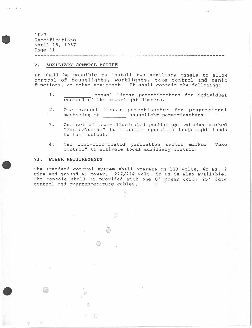
V. AUXILIARY CONTROL MODULE
It shall be possible to install two auxiliary panels to allow cont r o 1 of house 1 i g h t s , work 1 i g h t s , take cont r o 1 and pan i c functions, or other equipment. It shall contain the following:
1. manual linear potentiometers for individual control of the houselight dimmers.
2. One manual linear mastering of
potentiometer for proportional houselight potentiometers.
3. One set of rear-illuminated pushbutt~ switches marked "Panic/Normal" to transfer specified hou§elight loads to full output.
4. One rear-illuminated pushbutton switch marked "Take Control" to activate local auxiliary control.
VI. POWER REQUIREMENTS
The standard control system shall operate on 120 Volts, 60 Hz, 2 wire and ground AC power. 220/240 Volt, 50 Hz is also available. The console shall be provided with one 6" power cord, 25' data control and overtemperature cables. ~
.-

•
•
•
. ·.
Marketing Ne\Ns April 15, 1987 198720
A-C
Light Palette 3 GENERATION AFTER GENERATION
THE BEST KEEP GETTING .BETTER /'r""
Re~aining the most popular features of Light Palette 2 -
Default Profile Default Set
Remainder Dim Return
Proportional Patching
FEATURING THE FOLLOWING ENHANCEMENTS
Operator Selectable Default Track or Q-only
-- Default Fade Times --
-- 15 Playback Potentiometers with Unique Set Up Flexibility -which allows
Up to 13 Submasters Up to 6 Playback Faders
Bank Loading of Submasters
-- Submaster Bump Buttons --
Any Submaster With Overrange Capability
Any Submaster with Additive/Inhibitive Operation
Updated CRT Displays --
-- One console for Theatre and TV/Film
~ Strand Lighting Strand Lighting 18111 So. Santa Fe Ave. , P.O. Box 9004, Rancho Dominguez , _s:~ 90_2_2:4_ ~-S ·~ ·.T~I. (~1.3} ~~?·?~~

•
•
•
LP/3 encorporates the use of the same peripheral equipment as VB and TV2B. The console is available for shipment immediately. See LP/3 at USITT and Lighting World. Specifications are included. Contact quotations for pricing information.
Regards,
\\_r,s'--(_ Anne Morris Dimming and Control Product Manager
Attachment
.·
,, .-_.:
• F
•
\
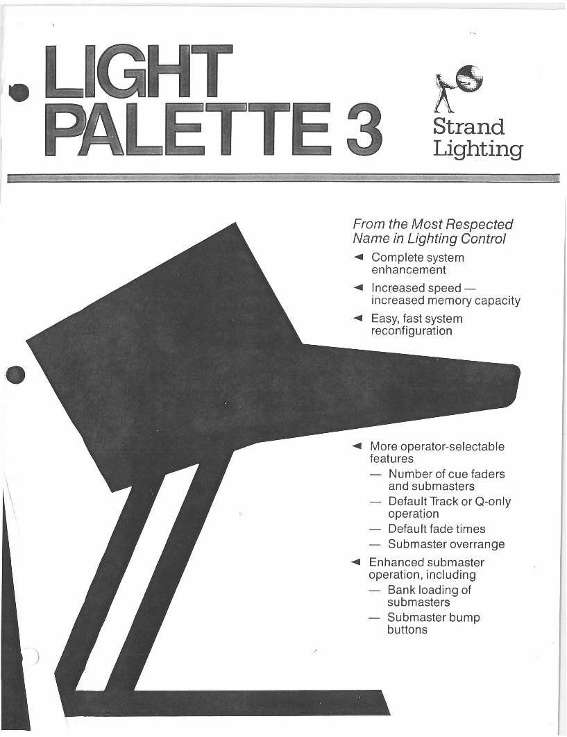
HT ETTE3 Strand
Lighting
From the Most Respected Name in Lighting Control ~ Complete system
enhancement
~ lnqeased speedincreased memory capacity
~ Easy, fast system reconfiguration
~ More operator-selectable features
Number of cue faders and submasters Default Track or Q-only operation Default fade times Submaster overrange
~ Enhanced submaster operation, including
Bank loading of submasters Submaster bump buttons
J