specifications for a self-contained, airless, … · specifications for a self-contained, airless,...
TRANSCRIPT

KELLY-CRESWELL 2000-AL REV C
SPECIFICATIONS FOR A SELF-CONTAINED, AIRLESS, PICK-UP MOUNTED, DOUBLE LINE
HIGHWAY MARKING MACHINE 2000-AL
GENERAL
1. The specifications are minimum requirements of a self-contained, pick-up truck mounted road marking machine ("The Unit").
2. The Unit shall be capable of applying lines of varied widths from 2" to 12" and the spaces between the lines variable from 0" to 6".
3. The paint guns shall be equipped with electro-air control valves so as to be under separate, accurate and positive control at all times.
4. The Unit shall be capable of applying all types of traffic paints at application speeds up to 15 mph. The machine shall be capable of applying conventional fast dry and waterborne marking materials.
5. The Unit shall be a one-man or two-man operation. In a one-man operation, the driver shall control all electronic controls from the cab of the vehicle. In a two-man operation, a second operator shall be positioned in one of the operator stations at the rear of the unit and shall have easy access to all controls. The Unit will operate in its own lane of traffic and not impede traffic in the on-coming lane.
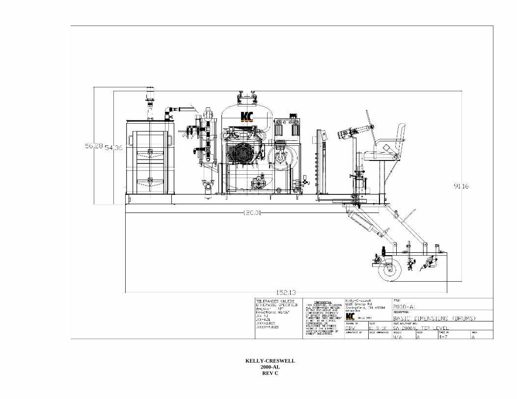
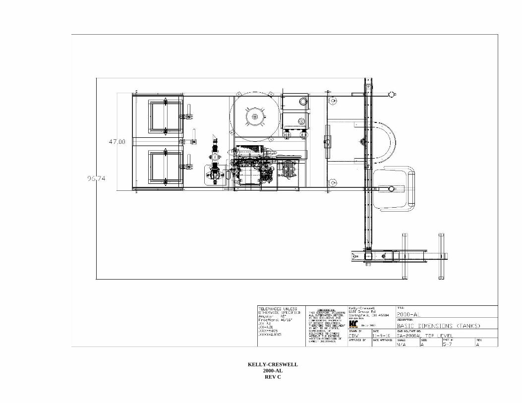
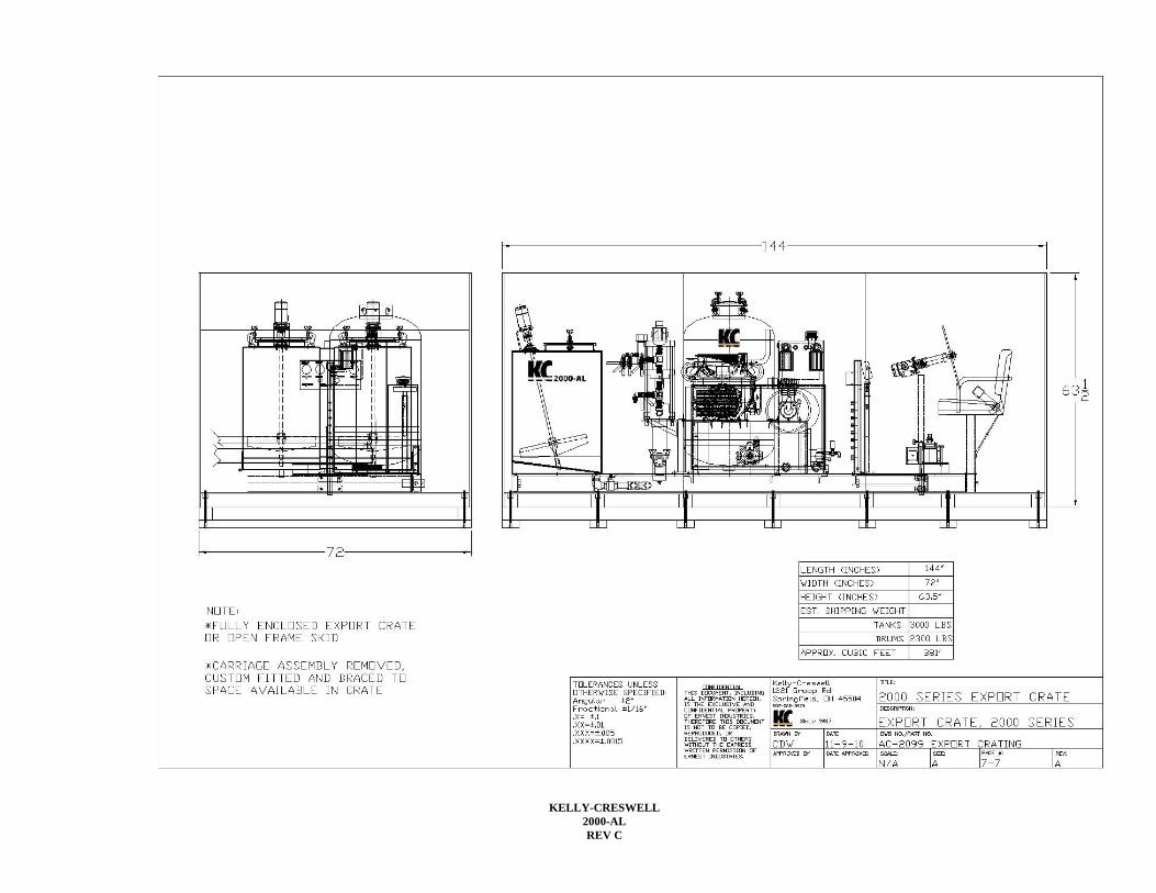
6. Dimensions: 120” Long X 48” Wide X 60” Tall (excluding carriage assembly) 7. Weight: 2,2,00-2,500 lbs depending on equipment installed. (not including operator, paint, beads or cleaner) 8. Chassis Requirements: Payload capacity 5,000 lbs, generally a “one ton” chassis. Consult your truck supplier to
verify GVW rating. FRAME
1. The unit shall be built on a steel platform constructed of heavy-duty 5” x 6.7# channel iron with cross members for support.
2. Lifting lugs shall be welded on the frame of the unit for lifting the unit. The lugs shall be placed to facilitate even distribution of weight.
3. Brackets will be provided to secure the unit to a flat bed style platform including four each brackets and 5/8” diameter grade 8 bolts, nuts and lock washers.
POWER UNIT/ENGINE
1. The power unit shall be powered by 20 gross horsepower industrial/commercial grade, twin cylinder gasoline engine, Honda GX630 or equal.
2. The engine shall be equipped with a 12 volt electric system with a 15 amp charging system. 3. The power unit shall be equipped with an oil level dip stick, a gearator oil pump and replaceable canister type oil
filter. 4. The engine will be with a key start switch and low pressure oil shut down system. 5. The power unit shall be equipped with a minimum 10 gallon fuel tank of all steel construction with internal
baffle. 6. The tank will be securely bolted to the main frame of the unit and feature a DOT approved vented cap assembly. 7. The engine will be equipped with an external 12VDC fuel pump and filter assembly. 8. A spark arresting quiet type muffler will be provided complete with extension pipe and rain cap. 9. The engine will be 50 state environmentally compliant.

KELLY-CRESWELL 2000-AL REV C
MATERIAL CONTAINERS (Select A, B, C, D or E)
A. Zero Pressure thee compartment vat, 60gallon paint X 15 gallon solvent X 60 gallon paint.
1. The Unit shall be equipped with a three (3) compartment, zero-pressure material container consisting of two (2) 60 gallon paint compartments and one (1) 15 gallon solvent compartment.
2. Each paint compartment shall be equipped with a minimum 12" square removable lid with solvent resistant gasket.
3. The tank shall be constructed of 11ga gauge stainless steel grade 304 and electrically welded at all joints. The bottom of each compartment shall have a minimum slope of 10 degrees towards the compartment outlet fitting to assure proper material flow.
4. The outlet of the paint tank shall be equipped with rigid pipe crossover manifold to allow separate or simultaneous use of each tank compartment.
5. The manifold shall be constructed of ASTM 1-1/4” schedule 40 stainless steel pipe with unions for convenient breakdown and three (3) each 1-1/4” full port SS ball valves.
6. The solvent compartment shall be valved to allow the introduction of cleaning solution to the airless pump, basket strainer, paint lines, and guns for the purpose of daily flushing or in field color change.
7. The unit shall be equipped with a separate cleaning hose to permit paint from the pump and filters to be returned to the paint tanks when cleaning, minimizing paint loss when cleaning.
B. Zero Pressure thee compartment vat, 75gal paint X 15 gal solvent X 75 gallon paint
1. Same specification as above (A), increase paint tank volume, 304 SS construction.
C. Zero Pressure three compartment 60 gal paint X 15 gal solvent X 60 gallon paint carbon steel construction.
1. Same specifications as above (A) change material to carbon steel construction. 2. Recommended for solvent based paints only.
D. Zero Pressure three compartment vat, 75 gal paint X 15 gal solvent X 75 gal paint carbon steel construction.
1. Same specifications as above (A) change material to carbon steel construction. 2. Recommended for solvent based paints only.
E. Paint Barrel Holders
1. The unit shall be equipped with a drum holder to secure two standard paint drums to the unit. 2. A suction tube stinger will be provided that fits thru the 2” NPT bung on a standard drum to draw paint
directly from the paint drum for striping. 3. A solvent bath for the singer will be provided complete with drain plug. 4. A reinforced safety plate will be provided for the drum to rest complete with a ring segment fabricated from
1/4” X 1” steel to keep drum captive. A structural tube frame will be provided to secure each drum with a ratchet type strap.
5. The drums will be easily accessible from either side of the machine for install and removal.

KELLY-CRESWELL 2000-AL REV C
COMPRESSOR
1. The compressor shall be a twin cylinder, single-stage, cast iron, air-cooled type having a minimum displacement of 13.1 CFM at 900 rpm at 100 pounds pressure.
2. The compressor shall be equipped with a pneumatic automatic un-loader device and an air receiver. 3. An adjustable pilot un-loader valve will be provided to unload compressor head when no demand for air. 4. The compressor shall be conveniently mounted on the unit for easy daily maintenance and access. 5. The compressor will be equipped with a replaceable air intake filter assembly. 6. The main airline from the compressor to the air receiver shall be 1” diameter, heat resistant and equipped with
reusable type fittings. 7. The pulley and external belts of the compressor and engine shall be covered with a metal belt guard.
HYDRAULIC SYSTEM
1. A dedicated pressure-compensating piston pump shall exclusively supply hydraulic oil to the airless paint pump. 2. The pump shall have a minimum capacity of 12 gallons per minute at 2,000 PSI. 3. The pressure-compensating piston pump shall draw minimal horsepower until there is a demand for paint at the
guns. The pump shall be directly coupled to an overhung load adapter to prevent side loading and excessive wear on the pump, attachment of a sheave directly to the hydraulic pump is not be permitted.
4. The pump will be equipped with an automatic electronic actuated valve to unload hydraulic pressure buildup when the engine is being started.
5. The airless hydraulic pump system will be equipped with a remote pressure adjusting valve located at the rear control panel to control hydraulic pump pressure from 300-2,000 psi.
6. An electronic actuated hydraulic valve will be provided to turn on/off hydraulic oil flow to the high pressure airless paint pump. Manual valves shall not be permitted.
7. The hydraulic system shall be equipped with an oil cooler mounted directly in front of engine flywheel. 8. The oil cooler will have a minimum of 107 square inches of cooling surface and equipped with a protective
sheet metal housing. HYDRAULIC RESERVOIR
1. The hydraulic system will be equipped with a 16 gallon hydraulic reservoir of all steel construction. 2. The reservoir shall be equipped with a vented breather cap, replaceable internal sump strainers with bypass, two
each 1” hydraulic return filters with replaceable filter cartridges. 3. The hydraulic tank will be unobstructed on all sides to quickly and evenly dissipate heat. 4. The tank will be equipped with internal baffles and a sight level gauge. 5. The tank will be mounted so that the inlet to the hydraulic pump(s) is flooded at all times.
SECONDARY HYDRAULIC PUMP
1. A second pressure compensated hydraulic pump will be provided for units equipped with optional hydraulic agitators and/or power steering.
2. The pump will be directly coupled to the rear of the main hydraulic pump and provide hydraulic oil to the hydraulic agitators and power steering.
3. The pump will be pressure compensated type with a capacity of 12 GPM at 2,000 psi. 4. The pump will draw little horsepower until there is a demand for oil at the agitators or power outrigger steering. 5. The pump will be equipped with a manual adjustable compensator. 6. Units with only power steering will be equipped with a gear type pump with a capacity of 8GPM. 7. The pump will be equipped with a safety pressure relief valve.
KELLY-CRESWELL 2000-AL REV C
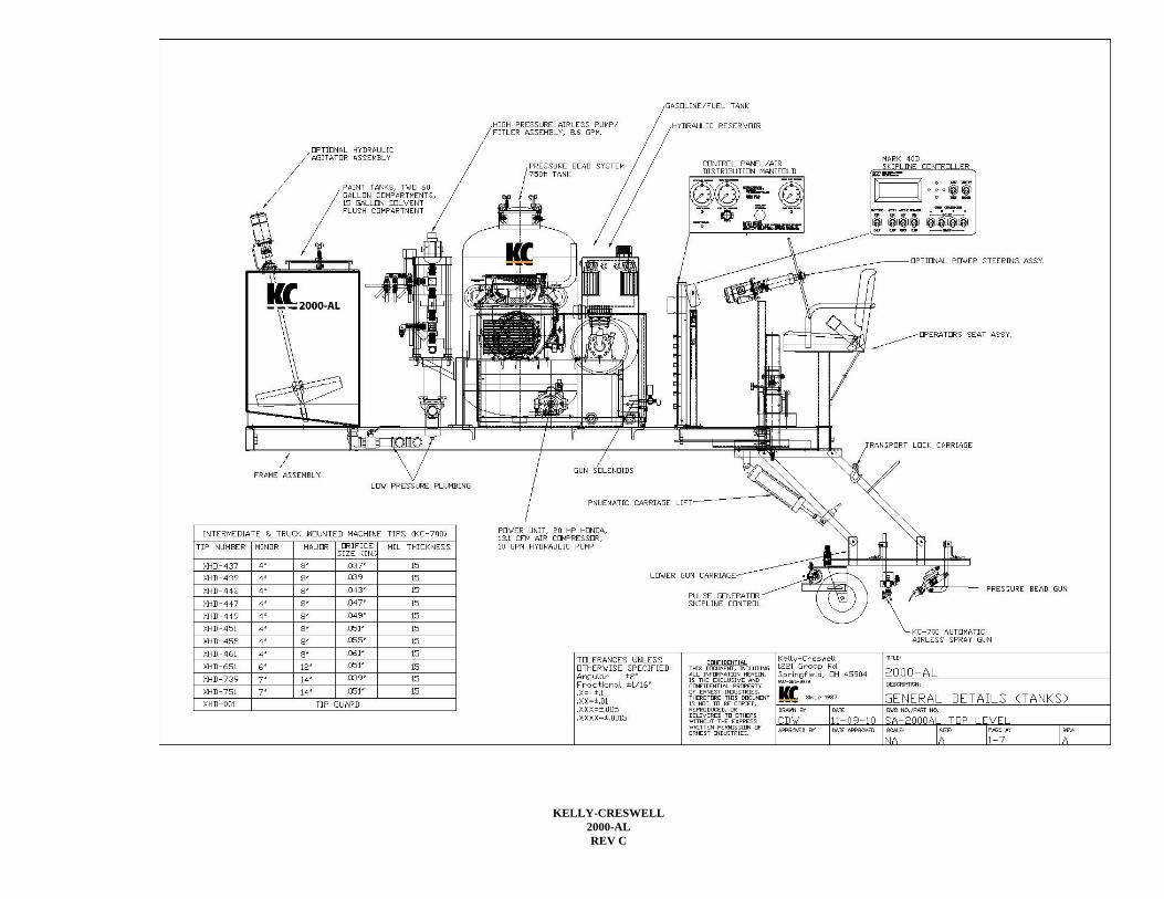
AIRLESS PAINT PUMP
1. The unit shall be equipped with one (1) high capacity, high pressure, piston type, hydraulically driven airless paint pump.
2. The airless paint pump shall have a minimum capacity of 8.6 GPM at discharge pressure of 2,000 psi. 3. The pump shall be capable of spraying waterborne (latex), alkyd (conventional solvent based) and chlorinated
rubber paints. 4. The pump shall be capable of spraying paints with standard solids content as well as low VOC, high solids paint. 5. The pump’s piston and sleeve shall be chrome plated for maximum corrosion and abrasion resistance. 6. The pump packing shall be ultra high molecular weight polyethylene and impregnated leather. 7. The pump throat packing shall be spring loaded to compensate for normal wear. 8. Paint pressure shall be fully adjustable from the operator’s station for paint pressures ranging from 0 to 2,000
PSI. 9. The unit shall be equipped with an electric actuated hydraulic shut off valve for the airless paint pump with the
switch located in the rear control panel. 10. Manual type hydraulic on/off valves not permitted. 11. A high pressure stainless steel check valve shall be installed between the paint pump outlet and paint filter. 12. A stainless steel pulsation dampener shall be installed to aid in the reduction of hour glassing of painted lines. 13. The pulsation dampener shall be equipped with a nitrogen charged viton bladder.
PAINT FILTRATION (LOW PRESSURE)
1. At the inlet port of the high pressure paint pump, paint shall pass through a "basket" type strainer with 1-1/2” NPT inlet/outlet fitting
2. The basket strainer will have a top opening removable screen with 1/8” diameter perforations. 3. The strainer screen shall be of all stainless steel construction minimum grade 304. 4. The screen will have a minimum of 28 square inches of filtration area.
PAINT FILTRATION (HIGH PRESSURE)
1. At the outlet port of the high pressure paint pump, there shall be one (1) high capacity, high pressure canister-type paint filter.
2. The high pressure filter shall have a removable, reusable stainless steel screen with a maximum of 30 mesh perforations.
3. The filter will feature removable top and ball check to prevent reverse flow of material. 4. The paint filter shall be rigid plumbed directly to the outlet of airless pump using, 2,000 psi fitting 304 SS
fittings. GUN CARRIAGE
1. The spray gun and bead gun carriage shall be electrically welded, all-steel construction. 2. One 3.00 x 5 all-pneumatic swivel wheel shall maintain the paint and bead guns at the same relative position
above the pavement at all times. 3. The swivel wheel pivot point shall be spring loaded with an adjustable tensioning nut. 4. The carriage shall be of parallel scissor-type construction and equipped with a safety hook to lock the carriage in
the up position for safe over-the-road travel. 5. The pivot points on the carriage will be equipped with replaceable oil impregnated bushing and hardened axles. 6. A 3’ x 9" pneumatic air cylinder shall be provided for automatic power lift to raise and lower the spray gun
carriage from the road surface. 7. The gun carriage will be installed on a 24" adjustable tube assembly to accommodate varying chassis heights. 8. The carriage will be quickly adjustable in 3" increments by removing a hardened bolt, nut and lock washer
assembly.
KELLY-CRESWELL 2000-AL REV C
OUTRIGGER ASSEMBLY
1. The gun carriage shall be attached to an outrigger that can trail from either the right or left rear side of the truck. 2. The outrigger shall be easily positioned to either side of the truck by pulling a pin and pivoting the outrigger by
means of a center pivot bearing. 3. The outrigger will be equipped with two 1-1/4” pillow block bearings firmly bolted to the main frame of the unit
acting as the main pivot point. 4. The outrigger will feature a structural steel bumper with a UMHW liner to prevent the outrigger from sagging when changing from center to edgeline positions.
OURTRIGGER STEERING: (Select A or B)
A. Manual rack & pinion outrigger steering 1. The outrigger will be equipped with manual rack & pinion steering assembly. 2. A 1” gear rack will be welded to the internal tube of the outrigger, roller chain not acceptable. 3. A hand wheel, approximately 12” in diameter will be provided to turn the gear rack assembly to position the outrigger. 4. The outrigger will be adjustable approximately 42”. 5. The hand wheel will be easily accessible from either operator’s station.
B. Hydraulic power outrigger steering.
1. The outrigger shall be equipped with a hydraulic power steering system adjustable to any position within a 36” operating range. 2. The outrigger shall be steerable from either the right or left rear operator’s position by a conventional automotive-type steering wheel. 3. Hydraulic quick disconnects will be provided to quickly and easily change hydraulic hoses when moving outrigger from side/side. 4. The hydraulic power outrigger steering will provide smooth continuous movement of the outrigger without hesitation or jerk. 5. The hydraulic power outrigger steering will get hydraulic power from a separate hydraulic pump exclusively for the power steering system and/or power steering & hydraulic paint tank agitators.
PAINT & BEAD GUNS
1. The unit shall be equipped with two (2) KC-700-SS high volume, stainless steel, high pressure, automatic, airless striping guns, (no exceptions).
2. The airless paint gun fluid chamber shall be constructed of stainless steel. The striping gun needle, needle ball, and seat shall be constructed of stainless steel and tungsten carbide.
3. The striping guns shall be equipped with reversible tips and shall be interchangeable without the use of tools for various spray patterns and flow rates.
4. The KC-700 spray guns will be mounted on an adjustable gun post for varying line widths and spacing between the lines.
5. The spray gun shall be small and compact for maximum visibility on the carriage, dimensions not to exceed 2.25” diameter x 6.75” long including tip guard.
6. The Unit shall be equipped with two (2) automatic, diaphragm-operated KC-600 high capacity pressure bead guns.
7. The KC-600 bead guns will be equipped with an adjustable shroud assembly to control the bead pattern width. 8. One (1) bead gun shall be mounted directly behind each paint gun. 9. The bead guns shall be capable of being operated simultaneously with the associated striping guns.

KELLY-CRESWELL 2000-AL REV C
10. The bead guns shall be fully adjustable for the desired application ratio of pounds of beads per gallon of paint.
BEAD DISPENSING EQUIPMENT
1. The Unit shall be equipped with a 750 pound capacity, carbon steel pressure bead tank, tested to a working pressure of 110 psi.
2. The bead tank lid shall have a minimum diameter of 10" and shall be held in place by four (4) over-the-center clamp and screw assemblies with forged steel wing head bolts.
3. The bead tank shall be equipped with a moisture trap with metal bowl, air pressure regulator, gauge, pop off valve and air bleed jet. A full steel skirt shall be provided around the bottom of the tank for flush mounting to the platform.
4. Pressure bead hoses with a minimum diameter of 1-1/4" ID shall be provided to convey the beads from the bead tank to a bead distribution manifold located at the rear of the Unit. Pressure bead hoses from the distribution block to the bead guns shall be 3/4" ID.
5. The pressure on the bead tank shall be fully adjustable from the rear operators’ position via an air regulator and related gauge.
ELECTRONIC SKIPLINE CONTROLLER
1. The Unit shall include one Mark 40 D skipline controller system. 2. The controller system shall be solid state, micro processor controlled and programmable. 3. The controller system shall consist of an operator's control panel located at operator's position that includes all the
necessary components and controls for programming, pattern selection, and gun control. 4. The control unit shall include one (1) two-line 32 character LCD display with adjustable contrast, one (1) five-
position push button programming panel, and nine (9) heavy duty military specification (MIL-S83731) toggle type switches with silicon rubber seals to prevent entry of contaminants.
5. Toggle switch contacts shall be silver-to-silver and all metal parts shall be corrosion resistant to ensure long service life and shall provide the following functions: master power, bead on-off, carriage lift/aux 1, auxiliary skip pattern/aux 2, gun control for each striping gun (skip-off-solid) and reset-hold (master gun on-off).
6. Programming the controller shall be possible through easy, menu driven procedures. All programming information shall be retained regardless of whether power is maintained.
7. Paint/skip cycle - 0 - 999.9 feet. Two preset cycles shall be programmable and selected by the cycle auxiliary cycle switch. A quick edit feature shall allow simple adjustment to the skip cycle while painting is in process.
8. Begin paint/skip. The controller shall be programmable to start with either the paint or skip portion of the cycle. 9. Calibration. Calibration of the unit shall be programmable and simply achieved by driving a known distance and
adjusting the displayed distance value. 10. Bead delay (if purchased). Delay between the paint and bead gun on and off shall be programmable to assure full
coverage by means of a mounting distance factor. Striping vehicle speeds shall not affect full bead coverage. Bead delay shall be factory preset and operator adjustable.
11. Solenoid timing calibration. Solenoid timing delay shall be programmable to adjust for the reaction time of different solenoids and control hose lengths. Solenoid shall be factory preset and operator adjustable.
12. Pattern change preset. The controller shall be programmable for three (3) different pattern change modes: immediate, smart and trigger.
13. The Hold-Run-Reset control shall allow the operator to conveniently move through intersections and to permit retracing of old patterns.
14. The Advance-Retard switch shall allow the operator to adjust the point at which the paint/skip cycle will begin. 15. The Posi-Cycle feature, shall automatically adjust the cycle length after activating the Advance-Retard switch
three times. 16. The controller shall be dust, water, and shock resistant. The operating range of the controller shall be from 30-
125° F. Power shall be provided by the vehicles 12 volt supply. All cables shall be plug-in type and a weatherproof cover shall be included.
17. In the ready mode, the controller shall display the skip line cycle, vehicle speed, painting in process indicator, and pulsed signal input indicator simultaneously. All footage display, whether cycle or skip length, odometer readings, footage counter readings, or calibration readings are displayed to the nearest 1/10’. The controller shall be capable of metric display.
18. All programming and accumulated information, footage and odometer readings, and calibration settings shall be retained indefinitely upon power down (whether accidental or intentional) or removal of the controller from the

KELLY-CRESWELL 2000-AL REV C
vehicle. All information shall be stored in non-volatile RAM chips and do not require batteries to retain programmed information.
19. The controller shall perform a complete self-test upon power up and alert the operator of short circuits. 20. The controller shall be equipped with a low speed speedometer displaying operating speed in the LCD display. 21. The controller shall be equipped with digital footage counters to totalize number of feet painted with each spray
gun. The footage counters shall be re-settable to zero. 22. The controller shall be equipped with a weatherproof vinyl cover to protect from moisture when not in use.
PLUMBING AND HOSE LINES
1. All plumbing lines from the material containers to the crossover manifold shall be ASTM specification 1 1/4" ID with unions, crosses, and tees liberally used throughout the plumbing installation to ensure convenient maintenance and cleanout.
2. Plumbing from the crossover manifold to the airless pump inlet shall be 1-1/4" ID flexible Teflon core chemical hose with stainless steel barbed fittings.
HIGH PRESSURE AIRLESS PAINT HOSES
1. All high pressure fluid hoses shall have a nylon core with a bonded urethane cover. 2. The hoses shall be static free and equipped with static conductive tube. 3. The hose shall be a minimum 3/8" I.D. with a minimum working pressure of 3,000 psi. 4. The hoses will be equipped with stainless steel female swivel pipe ends.
CONTROL HOSES
1. All control lines to the striping guns and electro-air valves shall be not less than 1/4" ID solvent resistant tubing. 2. All control lines shall use push-lock reusable fittings.
HYDRAULIC HOSES
1. All hydraulic pressure hoses shall be rated at a minimum of 2,500 psi working pressure. 2. The hoses shall be equipped with a rubber cover resistant to tears. 3. The fittings shall be crimp on type with JIC ends, pipe fittings are prohibited. 4. Suction and return hoses shall be rated at 250 psi and equipped crimp type JIC fittings. 5. Suction and return hoses with hose clamps are not permitted.
CONTROL PANEL/AIR RECEIVER
1. The Unit shall be equipped with a metal control panel located within reach of the rear operator. 2. The control panel shall be equipped with: main air pressure gauge, on/off switch for airless paint pump, air
regulator for pressure bead system, gauge for pressure bead tank, pressure reducing valve for hydraulic pump, gauge for hydraulic pump pressure and master electrical on/off switch.
3. Controls located at or on individual components shall not be acceptable. 4. Air regulators shall be non-corrosive, self-evacuating, and equipped with a locking device. 5. A plastic legend will be provided to identify all components on the control panel. 6. The legend will be marked from the reverse side to prevent fading and scratching. 7. The legend will have the serial number inscribed and be permanently attached to the control panel with silicone
adhesive. 8. Air moisture separator shall be provided to filter all air prior to passing through the air manifold. 9. The moisture trap will have a metal bowl with manual drain cock.
CONTROL SOLENOIDS
1. The unit will be equipped with KC-C5 electro-pneumatic control valves. 2. The control valves will control operation of paint guns, pressure bead guns and pneumatic carriage lift. 3. The control valves will be installed on a common bolt together manifold base complete
with o-ring seals. 4. The solenoids shall be two position 4 way valves.

KELLY-CRESWELL 2000-AL REV C
5. The valve shall have an operating pressure of 20-150 psi. 6. The valve shall have a three pin wire connector, waterproof with grommet. 7. The solenoid will have an LED light to indicate when operating. 8. The solenoid will have a manual test fire button to manually fire the solenoid. 9. The solenoid base and valve assembly shall be non corrosive aluminum.
GUIDE ASSEMBLY
1. The Unit shall be equipped with a removable, front mounted, adjustable pointer guide constructed of tubular steel.
2. The pointer shall be capable of pointing from both center & edgeline positions. Conventional style chassis (pickups) may require a special long pointer bar for pointing from edgeline side.
3. The pointer shall be installed on a 4" structural steel channel, with installation to chassis by others. 4. The pointer will collapse to a transport position to be within the limits of the vehicle. 5. A swivel road wheel will be provided with adjustable spring loaded road wheel.
PAINTING
1. The Unit shall be prime coated and finished painted Federal Highway Yellow unless otherwise specified. WARRANTY
1. The manufacturer will guarantee all parts against defective material and workmanship for a period of one year after date of delivery and acceptance subject to the terms and conditions in the attached Manufacturer's Warranty.
PARTS, SERVICE AND MANUALS
1. The Unit shall include one (1) complete set of operator's manuals and repair parts lists. 2. The Unit's manufacturer shall maintain a complete inventory of all replacement parts.
TECHNICAL SERVICE
1. Services of a factory technician shall be supplied to the customer at the plant in Springfield, Ohio, for a period of one (1) day to instruct customer personnel in the operation and maintenance of the Unit.
2. On-site instruction is available for an additional charge.
PART NUMBERS:
PART NUMBER MATERIAL CONTAINER OUTRIGGER STEERING
2000-AL-00110 Two 60 gallon vats with 15 gal solvent, SS construction Manual 2000-AL-00110-P Two 60 gallon vats with 15 gal solvent, SS construction Hydraulic Power 2000-AL-00112 Two 75 gallon vats with 15 gal solvent, SS construction Manual 2000-AL-00112-P Two 75 gallon vats with 15 gal solvent, SS construction Hydraulic Power 2000-AL-00111 Drum holders (2) Manual 2000-AL-00111-P Drum holders (2) Hydraulic Power 2000-AL-00114 Two 60 gallon vats with 15 gal solvent, carbon steel
construction* Manual
2000-AL-00113-P Two 60 gallon vats with 15 gal solvent, carbon steel construction*
Hydraulic Power
2000-AL-00113 Two 60 gallon vats with 15 gal solvent, carbon steel construction*
Manual

KELLY-CRESWELL 2000-AL REV C
2000-AL-00114-P Two 75 gallon vats with 15 gal solvent, carbon steel construction*
Hydraulic Power
*Recommend for oil based paints only

KELLY-CRESWELL 2000-AL REV C
Optional Equipment
Material Containers
AC- Carbon steel 60 or 75 gallon paint vats in lieu of stainless steel. Includes low pressure plumbing and basket strainer (carbon steel). High pressure plumbing and airless hoses remain stainless. Recommended for application of exclusively oil based paints.
Agitators, Hydraulic, Vat
AC-2150-1 Hydraulic driven paint vat agitators, stainless steel shafts and paddles, set of two. Includes additional hydraulic pump, needle valve controls to vary speed of agitators. Two each paddle assemblies shall be installed one each agitator shaft. The paddle mount shall be a two piece design for ease or removal after paint builds up on shaft.
Agitator, drum mounted, pneumatic.
AC-2150-2 Agitator, pneumatic drive for 55 gallon drum lid, one complete assembly. Includes bolt on fabricated assembly for air motor drive including 3/4" diameter stainless steel shaft two each stainless steel paddles. Air motor equipped with quick coupler, needle valve control and lubricator.
Agitator, drum mounted, hydraulic
AC-3040 Agitator, hydraulic drive for 55 gallon drum lid, one complete assembly. Includes bolt on fabricated assembly for hydraulic motor drive including 3/4" diameter stainless steel shaft two each stainless steel paddles. Hydraulic motor equipped with quick coupler and needle valve control.
Paint & Bead Guns
AC-2110 Additional KC-700 airless paint gun includes spray gun, gun hanger, gun post, fluid hose, KC-C5 actuation solenoid and airless paint hose.
AC-2120 Additional KC-700 airless paint gun and KC-600 pressure bead gun including guns hangers, guns posts, hoses, KC-C5 actuation solenoid, paint and bead hoses.
AC-2130 Timed beads, separate solenoid supplied to control pressure bead gun. This insures the entire painted line is covered with beads.
Hand Paint and Bead Guns
AC-2145 Hand airless paint gun with 50’ ¼ static grounded airless spray hose. Spray gun equipped with HDPT-517 airless tip.
AC-1040 Hand bead gun with 25’ bead hose. AC-1040-1 Combination hand airless spray gun and pressure bead gun with retractable
hose reel with 50’ of paint and bead hose. Bracket supplied to mount in unused seat pocket on rear of unit.
Intercom AC-2000 Intercom system, model 78C with two each voice activated head sets. Driver’s headset shall be a single ear and rear striper operators shall be a dual ear.
AC-2000-1 Intercom system, model 78C with two each voice activated head sets. Driver’s headset shall be a single ear and rear striper operators shall be a dual ear. Includes communication capability with other two way radios
Paint Loading AC-2060-1 Loading pump, 1” NPT air operated diaphragm pump, aluminum construction with two each 1” x 10’ loading hoses with quick disconnect fittings. A stinger shall be provided to draw paint from a standard drum. Pump mounted to unit location determined by customer. Recommended for oil based paints only.
AC-2060-2 Loading pump, 1” NPT air operated diaphragm pump, stainless construction with two each 1” x 10’ loading hoses with stainless quick disconnect fittings. A stinger shall be provided to draw paint from a standard drum. Pump mounted to unit location determined by customer. Recommended for latex/waterborne paints only.
AC-2061 Two wheeled cart for loading pump (cart only). Storage Cart AC-2098 Cart assembly, four each heavy-duty leg that bolt to channel iron frame. Legs
equipped with wheel for moving the unit on hard surface floor. Two Color Unit
AC-2 Color Unit equipped with second 8.6 GPM high pressure airless paint pump. Includes upgraded hydraulic system 20 GPM, upgraded engine Honda GX-690 34 gross HP. Unit manufactured on 60” wide frame in lieu of 48”.
Other Options

KELLY-CRESWELL 2000-AL REV C
Laser Pointer Laser guidance system, projects green dot on pavement surface for guidance. Available in manual and electronic adjustment.
Strobe Light Amber strobe, 12VDC mounted on pole. Directional
Arrow-board Directional arrow-board with brackets to mount to tank or mount to rear of frame, 24” X 48” with electronic tilt feature. Requires power from chassis.
Vacuum Bead Loading System
Vacuum bead loading system including vacuum pump, bead loading hose and combination bead barrel & bag splitter.
Trailer Optional trailer to mount the 2000-AL. Night Lights Night lighting package, 12VDC requires power from chassis. Training On Site
Training Factory direct technician for a period of one working day to instruct your personnel in the operation and maintenance of the unit.
Spare Parts 2000-AL Minor Common replacement parts for 2000-AL. 2000-AL Major Replacement parts inventory recommended for export sales.
KELLY-CRESWELL 2000-AL REV C

KELLY-CRESWELL 2000-AL REV C

KELLY-CRESWELL 2000-AL REV C
KELLY-CRESWELL 2000-AL REV C
KELLY-CRESWELL 2000-AL REV C

KELLY-CRESWELL 2000-AL REV C
KELLY-CRESWELL 2000-AL REV C