specification transformer
TRANSCRIPT

Date Place Signature & Seal of tenderer - 1 -
TECHNICAL SPECIFICATION FOR OUTDOORS TYPE SPECIAL DESIGNED LOAD SHEDDING TRANSFORMERS OF 11 KV CLASS UPTO AND INCLUDING30 AMP. WITH CRGO CORE.
1.0 SCOPE:(a) This specification covers, engineering, manufacture, assembly, stage testing, inspection and testing before supply and delivery at site of oil immersed, naturally cooled 6.640/10.120 KV , 24/15.7 Amp. AND 30/19.7 Amps. Special Designed Transformers.(b) The supplier shall have to produce an attested copy of the license of manufacturing of the Special DesignedTransformer from the patent holder of the concept (MGVCL/GUVNL).
1.1 It is not the intent to specify completely herein all the details of the design and construction of equipment. However the equipment shall conform in all respects to high standards of engineering, design and workmanship and shall be capable of performing in continuous commercial operation up to the Bidder’s guarantee, in a manner acceptable to the purchaser, who will interpret the meanings of drawings and specification and shall have the power to reject any work or material which, in his judgment is not in accordance therewith. The offered equipment shall be complete with all components necessary for their effective and trouble free operation. Such, components shall be deemed to be within the scope of Bidder’s supply irrespective of whether those are specifically brought out in this specification and / or the commercial order or not.
1.2 Standard Ratings:The Standard Ratings shall be 24 Amps & 30 Amps (Inputs)
1.3 No load voltage ratio : 6.640/10.120 KV for 11 kv class.1.4 The Special Designed Transformer will be stated as SDT henceforth.2.0 STANDARDS:
2.1. The materials shall conform in all respects to the relevant Indian / International Standard Specification, with latest amendments thereof, some of them are listed below:
Indian Standard Title International & Internationally recognised standard
ISS -2026/1977 Specification for Power Transformer IEC 76ISS – 1180 Outdoor distribution Transformer upto and
including 100 KvaIS 12444 Specification for Copper wire rod ASTM B-49
ISS -3347/1967 Specification for porcelain Transformer bushing DIN 42531,23,3ISS-335/1983 Specification for Transformer Oil BS 148, D-1473, D-1533- 1934
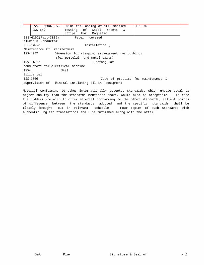
IEC Pub 296-1969ISS 5/1961 Specification for colors for ready mixed paintsISS - 2099/1973 Specification for High Voltage Porcelain bushingsISS - 7421/1974 Specification for Low Voltage bushingsISS – 3347 Specification for Outdoor Bushings DIN 42531 to 33ISS – 5484 Specification for Al Wire rods ASTM B - 233ISS – 9335 Specification for Insulating Kraft Paper IEC 554ISS – 1576 Specification for Insulating Press Board IEC 641ISS- 6600/1972 Guide for loading of oil Immersed Transformers IEC 76ISS-649 Testing of Steel Sheets & Strips For Magnetic
circuitsISS-6162(Part-I&II) Paper covered Aluminum ConductorISS-10028 Installation , Maintenance Of TransformersISS-4257 Dimension for clamping arrangement for bushings (for porcelain and metal
parts)ISS- 6160 Rectangular conductors for electrical machineISS- 3401 Silica gelISS-1866 Code of practice for maintenance & supervision of Mineral insulating oil in equipment
Material conforming to other internationally accepted standards, which ensure equal or higher quality than the standards mentioned above, would also be acceptable. In case the Bidders who wish to offer material conforming to the other standards, salient points of difference between the standards adopted and the specific standards shall be clearly brought out in relevant schedule. Four copies of such standards with authentic English translations shall be furnished along with the offer.
Date Place Signature & Seal of tenderer - 2 -
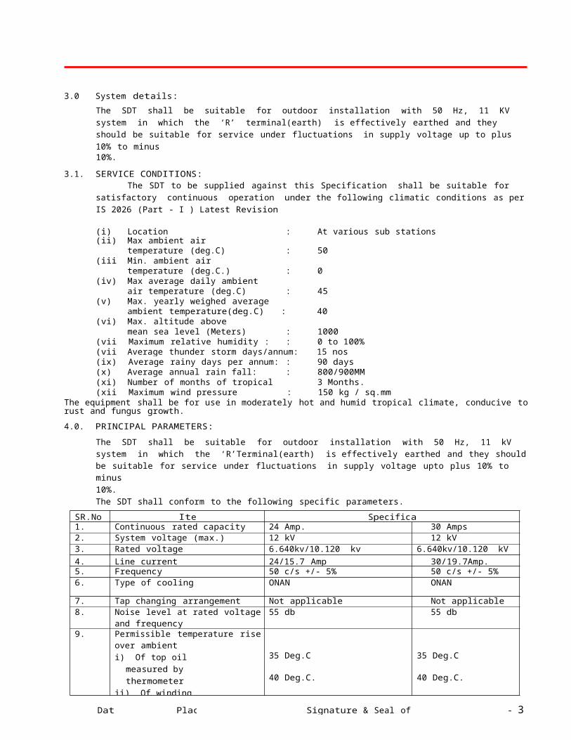
3.0 System details:
The SDT shall be suitable for outdoor installation with 50 Hz, 11 KV system in which the ‘R’ terminal(earth) is effectively earthed and they should be suitable for service under fluctuations in supply voltage up to plus 10% to minus10%.
3.1. SERVICE CONDITIONS:The SDT to be supplied against this Specification shall be suitable for satisfactory continuous operation under
the following climatic conditions as per IS 2026 (Part - I ) Latest Revision
(i) Location : At various sub stations in Gujarat(ii) Max ambient air
temperature (deg.C) : 50(iii) Min. ambient air
temperature (deg.C.) : 0(iv) Max average daily ambient
air temperature (deg.C) : 45(v) Max. yearly weighed average
ambient temperature(deg.C) : 40(vi) Max. altitude above
mean sea level (Meters) : 1000(vii) Maximum relative humidity : : 0 to 100%(viii) Average thunder storm days/annum: : 15 nos(ix) Average rainy days per annum: : 90 days(x) Average annual rain fall: : 800/900MM(xi) Number of months of tropical monsoon: : 3 Months.(xii) Maximum wind pressure : 150 kg / sq.mm
The equipment shall be for use in moderately hot and humid tropical climate, conducive to rust and fungus growth.
4.0. PRINCIPAL PARAMETERS:
The SDT shall be suitable for outdoor installation with 50 Hz, 11 kV system in which the ‘R’Terminal(earth) is effectively earthed and they should be suitable for service under fluctuations in supply voltage upto plus 10% to minus10%.The SDT shall conform to the following specific parameters.
SR.No Item Specification1. Continuous rated capacity 24 Amp. 30 Amps2. System voltage (max.) 12 kV 12 kV3. Rated voltage 6.640kv/10.120 kv 6.640kv/10.120 kV4. Line current 24/15.7 Amp 30/19.7Amp.5. Frequency 50 c/s +/- 5% 50 c/s +/- 5%6. Type of cooling ONAN ONAN
7. Tap changing arrangement Not applicable Not applicable8. Noise level at rated voltage
and frequency55 db 55 db
9. Permissible temperature riseover ambienti) Of top oil measured
by thermometerii) Of winding measured
by resistance
35 Deg.C
40 Deg.C.
35 Deg.C
40 Deg.C.
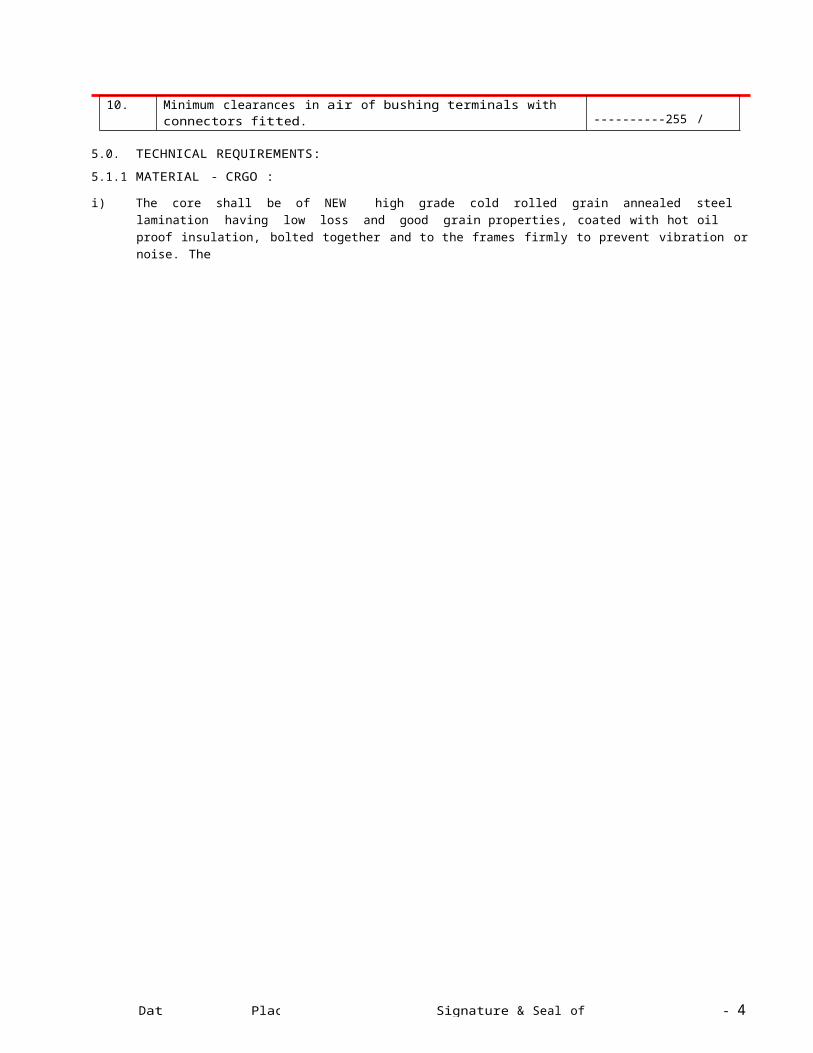
10. Minimum clearances in air of bushing terminals with connectors fitted.a) HV phase to phase/ phase to earth (mm) ----------255 / 205---------
5.0. TECHNICAL REQUIREMENTS:
5.1.1 MATERIAL - CRGO :
i) The core shall be of NEW high grade cold rolled grain annealed steel lamination having low loss and good grain properties, coated with hot oil proof insulation, bolted together and to the frames firmly to prevent vibration or noise. The
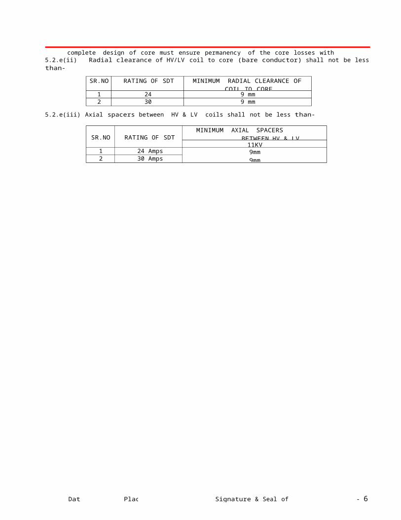
complete design of core must ensure permanency of the core losses with continuous working of the transformers. The
Date Place Signature & Seal of tenderer - 3 -
value of the maximum flux density allowed in the design and grade of lamination used shall be clearly stated in the offer.ii) Core Clamping for CRGO :
1. MS channel shall be used on top and bottom2. Core Channel on LV side to be reinforced at equidistance, if holes / cutting is done for LT lead in order to avoid
bending of channel.3. MS Channels shall be painted with varnish or hot oil-resistant paint.
iii) The transformers core shall be suitable for over fluxing (due to combined effect of voltage and frequency) upto 12.5% without injurious heating at full load conditions and shall not get saturated. The Bidder shall furnish necessary design data in support of this situation.
iv) The nominal flux density in any part of the core shall not exceed 1.69 Tesla at 1.0 p.u.voltage and 1.9 Tesla at 1.1 p.u.voltage.The vendor shall furnish necessary design data in support of this stipulation.
v) No load current shall not exceed 3% of full load current and will be measured by energising the transformer at 6640 volts, 50 c/s on the primary. Increase of voltage of 6640 volts by 12.5% shall not increase the no load current by Max. 6% of full load current.
vi) Clamping and Tie-rods shall be made from HT steel & shall be parkarised.
5.2 WINDINGS:
5.2.a. Materials:- Double paper covered aluminum conductor shall be used for 11 KV class transformer. A mix of copper &aluminum conductors for HV & LV winding will not be permitted.
5.2.b. Current density for HV and LV shall not be more than 2.5 A/sq.mm. for copper and 1.60 A/sq.mm. for aluminum conductor. (However, +5% tolerance for LV winding is permissible)
5.2.c. H.V. Cross Section for aluminium conductor shall not be less than
Sr. No.
RATING OF SDT VOLTAGE CLASS OF SDT11 KV
1 24 Amp 5.2 sq.mm2 30 Amp 6.5 sq.mm
5.2.d L.V. Cross Section aluminium conductor shall not be less than
Sr. No.
RATING OF SDT VOLTAGE CLASS OF SDT
11 KV1 24 Amp 9.9 sq.mm2 30 Amp 12.4 sq.mm
(-5% tolerance is permissible for all rating of transformers)
Note: Manufacturer shall provide higher cross sections as required to keep winding& oil Temp. as specified, within limit.
5.2.e. I n s u l at i on m at er i a l & cle a r a n ce s :
5.2..e (i). Materials Electrical grade insulating craft paper of Triveni/Ballarpur/Cauvery or equivalent make subject to approval of the purchaser shall be used. Similarly Press Board of Senapaty, Whitelay or Raman make or equivalent subject to the approval of the purchaser shall be used. Perma wood or Haldi wood blocks shall be used for top and bottom yoke insulation.
5.2.e(ii) Radial clearance of HV/LV coil to core (bare conductor) shall not be less than-
SR.NO RATING OF SDT MINIMUM RADIAL CLEARANCE OF COIL TO CORE
1 24 Amps 9 mm2 30 Amps 9 mm
5.2.e(iii) Axial spacers between HV & LV coils shall not be less than-
SR.NO RATING OF SDTMINIMUM AXIAL SPACERS BETWEEN
HV & LV11KV
1 24 Amps 9mm9mm2 30 Amps
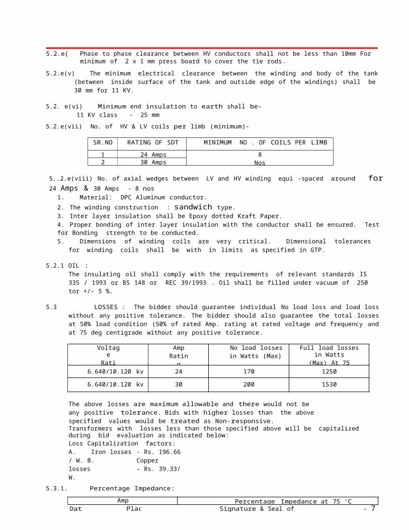
5.2.e(iv) Phase to phase clearance between HV conductors shall not be less than 10mm For 11 KV class with a provision of
Date Place Signature & Seal of tenderer - 4 -
minimum of 2 x 1 mm press board to cover the tie rods.
5.2.e(v) The minimum electrical clearance between the winding and body of the tank (between inside surface of the tank and outside edge of the windings) shall be 30 mm for 11 KV.
5.2. e(vi) Minimum end insulation to earth shall be-11 KV class - 25 mm
5.2.e(vii) No. of HV & LV coils per limb (minimum)-
SR.NO RATING OF SDT MINIMUM NO . OF COILS PER LIMB
1 24 Amps 8 Nos8 Nos2 30 Amps
5..2.e(viii) No. of axial wedges between LV and HV winding equi -spaced around for 24 Amps & 30 Amps - 8 nos1. Material: DPC Aluminum conductor.
2. The winding construction : sandwich type.3. Inter layer insulation shall be Epoxy dotted Kraft Paper.4. Proper bonding of inter layer insulation with the conductor shall be ensured. Test for Bonding strength to be conducted.5. Dimensions of winding coils are very critical. Dimensional tolerances for winding coils shall be with in limits as
specified in GTP.
5.2.1 OIL :The insulating oil shall comply with the requirements of relevant standards IS 335 / 1993 or BS 148 or REC 39/1993 . Oil shall be filled under vacuum of 250 tor +/- 5 %.
5.3 LOSSES : The bidder should guarantee individual No load loss and load loss without any positive tolerance. The bidder should also guarantee the total losses at 50% load condition (50% of rated Amp. rating at rated voltage and frequency and at 75 deg centigrade without any positive tolerance.
VoltageRatio
AmpRating
No load lossesin Watts (Max)
Full load losses in Watts(Max) At 75 Deg. c.
6.640/10.120 kv 24 170 1250
6.640/10.120 kv 30 200 1530
The above losses are maximum allowable and there would not be any positive tolerance. Bids with higher losses than the above specified values would be treated as Non-responsive.Transformers with losses less than those specified above will be capitalized during bid evaluation as indicated below:Loss Capitalization factors:A. Iron losses - Rs. 196.66 / W. B. Copper losses - Rs. 39.33/ W.
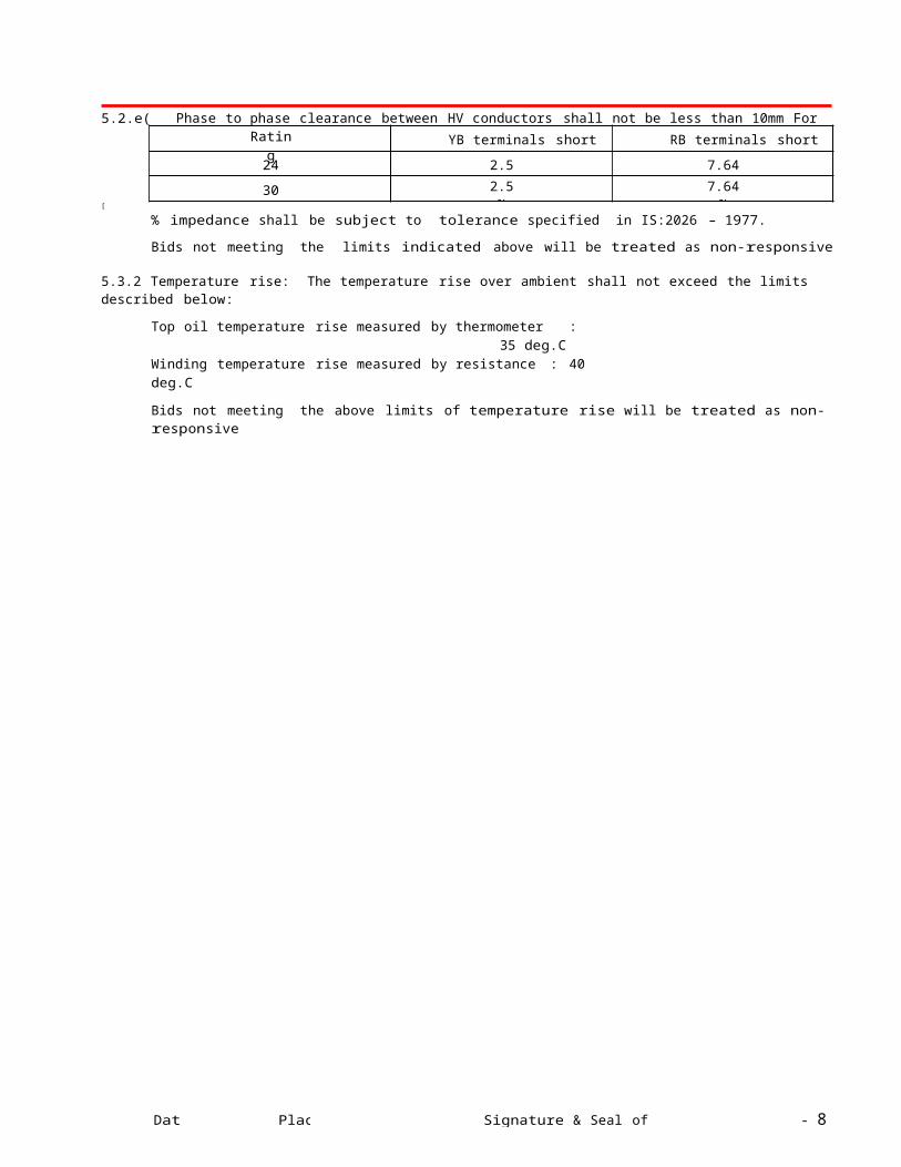
5.3.1. Percentage Impedance:
AmpRating
Percentage Impedance at 75 ‘C
YB terminals short RB terminals short
24 2.5 % 7.64 %
30 2.5 % 7.64 %
[
% impedance shall be subject to tolerance specified in IS:2026 – 1977.
Bids not meeting the limits indicated above will be treated as non-responsive
5.3.2 Temperature rise: The temperature rise over ambient shall not exceed the limits described below:
Top oil temperature rise measured by thermometer : 35 deg.C Winding temperature rise measured by resistance : 40 deg.C
Bids not meeting the above limits of temperature rise will be treated as non-responsive

Date Place Signature & Seal of tenderer - 5 -
5.4 PENALTY FOR NON PERFORMANCE:
5.4.1. During testing, if it is found that the actual measured losses are more than the values quoted by the bidder, the purchaser will have right to exercise one of the following options
a) Reject the complete lot
b) Penalty shall be recovered from the bidder for the excess losses as under
No load loss - @ Rs 395.00 per watt
Load Loss at 100%load - @79.00 per watt
5.4.2. SDT with temperature rise and impedance beyond guaranteed values:
5.4.2.1. Purchaser reserves the right to reject the available lot of the such transformer in any sample of the transformer during the test at supplier's works, if the temperature rise exceeds the guaranteed values.
5.4.2.2 Purchaser reserves the right to reject any transformer during the test at supplier’s works, if the impedance values differ from the guaranteed values including tolerance.
5.4.2.3 Purchaser also reserves the right to retain the rejected transformer and take it into service until the Bidder replaces it with a new transformer at no extra cost. The delivery as per contract will be counted when the new transformer as per specification is provided by the manufacture.
5.5 INSULATION MATERIAL :
a) Material: Electrical grade insulation Kraft Paper of standard make or better material subject to approval of the purchaser. Pressboard of standard make or better material subject to approval of purchaser.
b) All spacers, axial wedges / runners used in windings shall be made of pre-compressed Pressboard−solid, conforming to type B 3.1 of IEC 641-3-2. In case of cross-over coil winding of HV all spacers shall be properly sheared and dovetail punched to ensure proper locking. All axial wedges / runners shall be properly milled to dovetail shape so that they pass through the designed spacers freely. Insulation shearing, cutting, milling and punching operations shall be carried out in such a way, that there should not be any burr and dimensional variations.
5.6 TANK:The transformer tank can be with radiator fins/ rounded or elliptical cooling tubes or made of corrugated panels. Radiator shall be provided on both the side of the tank.
For Rectangular plain tank:
i. The transformer tank shall be of robust construction rectangular in shape and shall be built up of tested MS sheets.ii. The internal clearance of tank shall be such that, it shall facilitate easy lifting of core with coils from the tank without
dismantling bushings.
iii. All joints of tank and fittings shall be oil tight and no bulging should occur during service. The tank design shall be such that the core and windings can be lifted freely. The tank plate shall be of such strength that the complete transformers when filled with oil may be lifted bodily by means of lifting lugs. Inside of tank shall be painted with hot oil resistive paint only.
iv. Manufacturer should carry out all welding operations as per the relevant ASME standards and submit a copy of the welding procedure qualifications and welder performance qualification certificates to the customer.
v. The four walls of the tank shall be made of Two “L” shaped sheets (without joints) fully welded at the corners from inside and outside of the tank for withstanding a pressure of 0.8 kg/cm
2 for 10 minutes.
vi. The tank shall be reinforced by welded angle on all the outside walls on the edge of the tank to form two equal compartments. Permanent deflection when the tank without oil is subject to a vacuum of 525 mm of mercury for rectangular tank and 760 mm of mercury for round tank, shall not be more than 5 mm upto 750 mm length and 6 mm upto 1250 mm length. The tank shall further be capable of withstanding a pressure of 0.8 kg/sq.cm (g) and a vacuum of0.3 kg/sq.cm(g) without any deformation.
vii. The radiators can be tube type or fin type or pressed steel type to achieve the desired cooling to limit the specified temperature rise. The transformer shall be capable of giving continuous rated output without exceeding the specified temperature rise. Bidder shall submit the calculation sheet.
viii. Lifting lugs: 4 Nos. welded heavy duty lifting lugs of MS plate 8 mm thick (min) suitably reinforced by vertical supporting flat welded edgewise below the lug on the side wall.
ix. Pulling lugs: 4 Nos. of welded heavy duty pulling lugs of MS plate 8 mm thick (min) shall be provided to pull the transformer horizontally.
x. Top cover fixing bolts of G.I adequately spaced and 6 mm Neoprene bonded cork gaskets conforming to IS 4253 part-IIshall be placed between tank and cover. The bolts outside tank shall have 2 flat washers & one spring washer.
Date Place Signature & Seal of tenderer - 6 -
5.6.8. ConservatorOn Transformers of all ratings with rectangular plain tank the provision of conservators is required.Conservator tank is provided with oil gauge and the plain or dehydrating breathing devise shall be fixed to the conservator which shall also be provided with a drain plug and a filling hole (1¼" normal size thread) with cover. The capacity of a conservator tank shall be designed to contain 10% of the total quantity of oil and its contraction and expansion due to temperature variations. Normally 3% quantity of total oil will be contained in the conservator. In addition the cover of main tank shall be provided with an air release plug to enable air trapped within to be released, unless the conservator is so located as to eliminate the possibility of air being trapped within the main tank.
The inside diameter of the pipe connecting the conservator to the main tank should be within 30 to 50 mm and it should be projected into the conservator so that its end is approximately 20 mm above the bottom of the conservator so as to create a sump for collection of impurities. The minimum oil level ( corresponding to -5 deg C) should be above the sump level.
5.6.9. B r e a t h e r :Breather shall be screwed type. It shall have die cast aluminum body & further, inside container for silica gel shall be of tin sheet, Volume of Silica gel breather shall be 0.5 Kg. The make and design of breather shall be subject to approval of UGVCL. Inverted U-shape pipe shall be used for connection of breather.
5.7 SURFACE PREPARATION & PAINTING
5.7.1. G e n e r a l
5.7. 1.1 All paints shall be applied in accordance with the paint manufacturer’s recommendations. Particular attention shall be paid to the following:
a) Proper storage to avoid exposure as well as extremes of temperature. b) Surface preparation prior to painting.c) Mixing and thinningd) Application of paints and the recommended limit on time intervals
between coats.e) Shelf life for storage
5.7.1.2 All paints, when applied in a normal full coat, shall be free from runs, sags, wrinkles, patchiness, brush marks or other defects.
5.7.1.3 All primers shall be well marked into the surface, particularly in areas where painting is evident, and the first priming coat shall be applied as soon as possible after cleaning. The paint shall be applied by airless spray according to manufacturer’s recommendations. However, where ever airless spray is not possible, conventional spray be used with prior approval of purchaser.
5.7.1.4 The Supplier shall, prior to painting protect nameplates, lettering gauges, sight glasses, light fittings and similar suchitems.
5.7.2. C le a n i n g a n d Su r f a c e P r e p a r a t i o n
5.7.2.1 After all machining, forming and welding has been completed, all steel work surfaces shall be thoroughly cleaned of rust, scale, welding slag or spatter and other contamination prior to any painting.
5.7.2.2 Steel surfaces shall be prepared by Shot blast cleaning or Chemical cleaning by Seven Tank process includingPhosphating to the appropriate quality.
5.7.2.3 The pressure and volume of the compressed air supply for blast cleaning shall meet the work requirements and shall be sufficiently free from all water contamination to ensure that the cleaning process is not impaired.
5.7.2.4 Chipping, scraping and steel wire brushing using manual or power driven tools cannot remove firmly adherent mill-scale shall only be used where blast cleaning is impractical. Manufacturer to explain such areas in his technical offer clearly.
5.7.3. P r ot ec t i ve C o at i n g 5.7.3.1 As soon as all items have been cleaned and within four hours of the subsequent drying, they shall be given suitable
anti- corrosion protection.
5.7.4. P a i n t M a t e r i a l
Followings are the types of paint that may be suitably used for the items to be painted at shop and supply of matching paint to site:
5.7.4.1 Heat resistant paint (Hot oil proof) for inside surface.
5.7.4.2 For external surfaces one coat of Thermo Setting Powder paint or 1 coats of Zinc chromate primer followed by 2 coats of Synthetic Enamel / Polyurethene base Paint These paints can be either air drying or stoving.
Date Place Signature & Seal of tenderer - 7 -
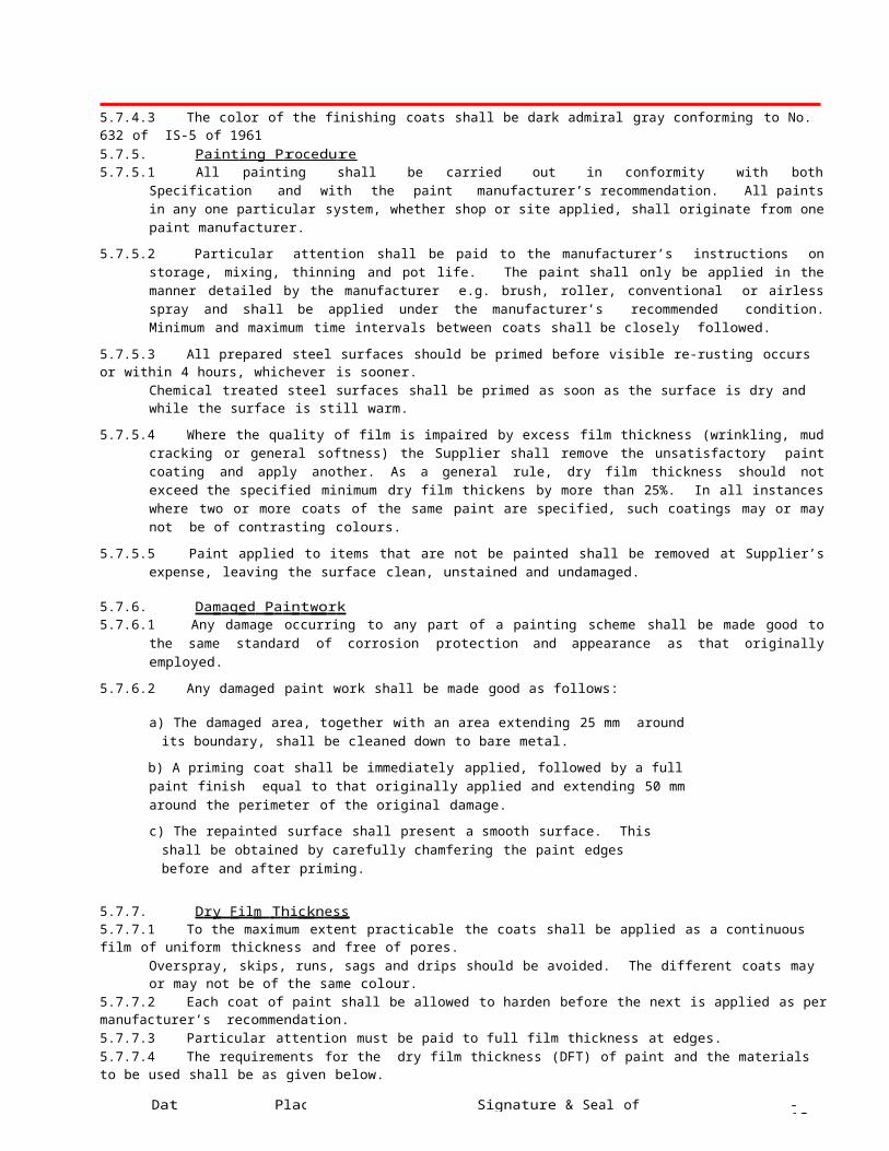
5.7.4.3 The color of the finishing coats shall be dark admiral gray conforming to No. 632 of IS-5 of 19615.7.5. P a i n t i n g P r o c e du r e 5.7.5.1 All painting shall be carried out in conformity with both Specification and with the paint manufacturer’s
recommendation. All paints in any one particular system, whether shop or site applied, shall originate from one paint manufacturer.
5.7.5.2 Particular attention shall be paid to the manufacturer’s instructions on storage, mixing, thinning and pot life. The paint shall only be applied in the manner detailed by the manufacturer e.g. brush, roller, conventional or airless spray and shall be applied under the manufacturer’s recommended condition. Minimum and maximum time intervals between coats shall be closely followed.
5.7.5.3 All prepared steel surfaces should be primed before visible re-rusting occurs or within 4 hours, whichever is sooner.Chemical treated steel surfaces shall be primed as soon as the surface is dry and while the surface is still warm.
5.7.5.4 Where the quality of film is impaired by excess film thickness (wrinkling, mud cracking or general softness) the Supplier shall remove the unsatisfactory paint coating and apply another. As a general rule, dry film thickness should not exceed the specified minimum dry film thickens by more than 25%. In all instances where two or more coats of the same paint are specified, such coatings may or may not be of contrasting colours.
5.7.5.5 Paint applied to items that are not be painted shall be removed at Supplier’s expense, leaving the surface clean, unstained and undamaged.
5.7.6. Da m a g e d P a i n t w o r k 5.7.6.1 Any damage occurring to any part of a painting scheme shall be made good to the same standard of corrosion protection
and appearance as that originally employed.
5.7.6.2 Any damaged paint work shall be made good as follows:
a) The damaged area, together with an area extending 25 mm around its boundary, shall be cleaned down to bare metal.
b) A priming coat shall be immediately applied, followed by a full paint finish equal to that originally applied and extending 50 mm around the perimeter of the original damage.
c) The repainted surface shall present a smooth surface. This shall be obtained by carefully chamfering the paint edges before and after priming.
5.7.7. D r y F il m T h i c kn e s s 5.7.7.1 To the maximum extent practicable the coats shall be applied as a continuous film of uniform thickness and free of pores.
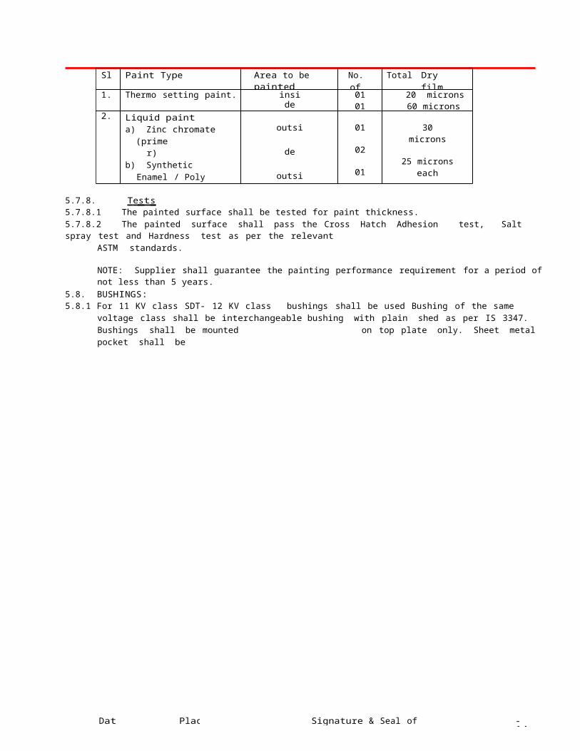
Overspray, skips, runs, sags and drips should be avoided. The different coats may or may not be of the same colour.5.7.7.2 Each coat of paint shall be allowed to harden before the next is applied as per manufacturer’s recommendation.5.7.7.3 Particular attention must be paid to full film thickness at edges.5.7.7.4 The requirements for the dry film thickness (DFT) of paint and the materials to be used shall be as given below.
Sl. No.
Paint Type Area to be painted No. of coats
Total Dry film thickness (min.)
1. Thermo setting paint. insideoutside
0101
20 microns60 microns
2. Liquid painta) Zinc chromate
(primer)b) Synthetic Enamel /
Poly Urethene (Finish coat)
c) Hot oil paint / Varnish
outside
outside
inside
01
02
01
30 microns
25 microns each
35 / 10 microns
5.7.8. T e s t s 5.7.8.1 The painted surface shall be tested for paint thickness.5.7.8.2 The painted surface shall pass the Cross Hatch Adhesion test, Salt spray test and Hardness test as per the relevant
ASTM standards.
NOTE: Supplier shall guarantee the painting performance requirement for a period of not less than 5 years.5.8. BUSHINGS:5.8.1 For 11 KV class SDT- 12 KV class bushings shall be used Bushing of the same voltage class shall be interchangeable
bushing with plain shed as per IS 3347. Bushings shall be mounted on top plate only. Sheet metal pocket shall be
Date Place Signature & Seal of tenderer - 8 -
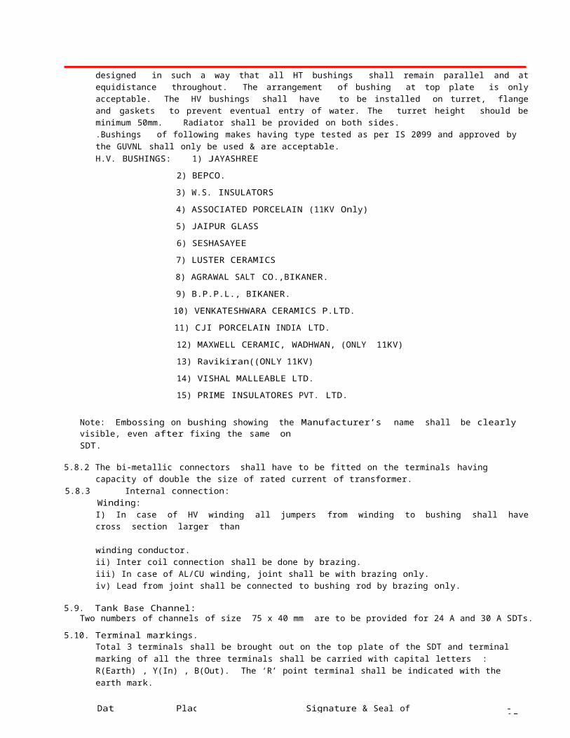
designed in such a way that all HT bushings shall remain parallel and at equidistance throughout. The arrangement of bushing at top plate is only acceptable. The HV bushings shall have to be installed on turret, flange and gaskets to prevent eventual entry of water. The turret height should be minimum 50mm. Radiator shall be provided on both sides..Bushings of following makes having type tested as per IS 2099 and approved by the GUVNL shall only be used & are acceptable.H.V. BUSHINGS: 1) JAYASHREE
2) BEPCO.
3) W.S. INSULATORS
4) ASSOCIATED PORCELAIN (11KV Only)
5) JAIPUR GLASS
6) SESHASAYEE
7) LUSTER CERAMICS
8) AGRAWAL SALT CO.,BIKANER.
9) B.P.P.L., BIKANER.
10) VENKATESHWARA CERAMICS P.LTD.
11) CJI PORCELAIN INDIA LTD.
12) MAXWELL CERAMIC, WADHWAN, (ONLY 11KV)
13) Ravikiran((ONLY 11KV)
14) VISHAL MALLEABLE LTD.
15) PRIME INSULATORES PVT. LTD.
Note: Embossing on bushing showing the Manufacturer’s name shall be clearly visible, even after fixing the same onSDT.
5.8.2 The bi-metallic connectors shall have to be fitted on the terminals having capacity of double the size of rated current of transformer.
5.8.3 Internal connection:Winding:I) In case of HV winding all jumpers from winding to bushing shall have cross section larger than winding conductor.ii) Inter coil connection shall be done by brazing.iii) In case of AL/CU winding, joint shall be with brazing only.iv) Lead from joint shall be connected to bushing rod by brazing only.
5.9. Tank Base Channel:Two numbers of channels of size 75 x 40 mm are to be provided for 24 A and 30 A SDTs.
5.10. Terminal markings.Total 3 terminals shall be brought out on the top plate of the SDT and terminal marking of all the three terminals shall be carried with capital letters : R(Earth) , Y(In) , B(Out). The ‘R’ point terminal shall be indicated with the earth mark.
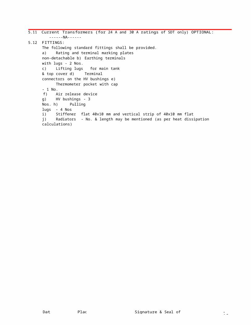
5.11 Current Transformers (for 24 A and 30 A ratings of SDT only) OPTIONAL:------NA------
5.12 FITTINGS:The following standard fittings shall be provided.a) Rating and terminal marking plates non-detachable b) Earthing terminals with lugs - 2 Nos.c) Lifting lugs for main tank & top cover d) Terminal connectors on the HV bushings e) Thermometer pocket with cap - 1 No.f) Air release device
g) HV bushings - 3 Nos. h) Pulling lugs - 4 Nosi) Stiffener flat 40x10 mm and vertical strip of 40x10 mm flatj) Radiators - No. & length may be mentioned (as per heat dissipation calculations)
Date Place Signature & Seal of tenderer - 9 -
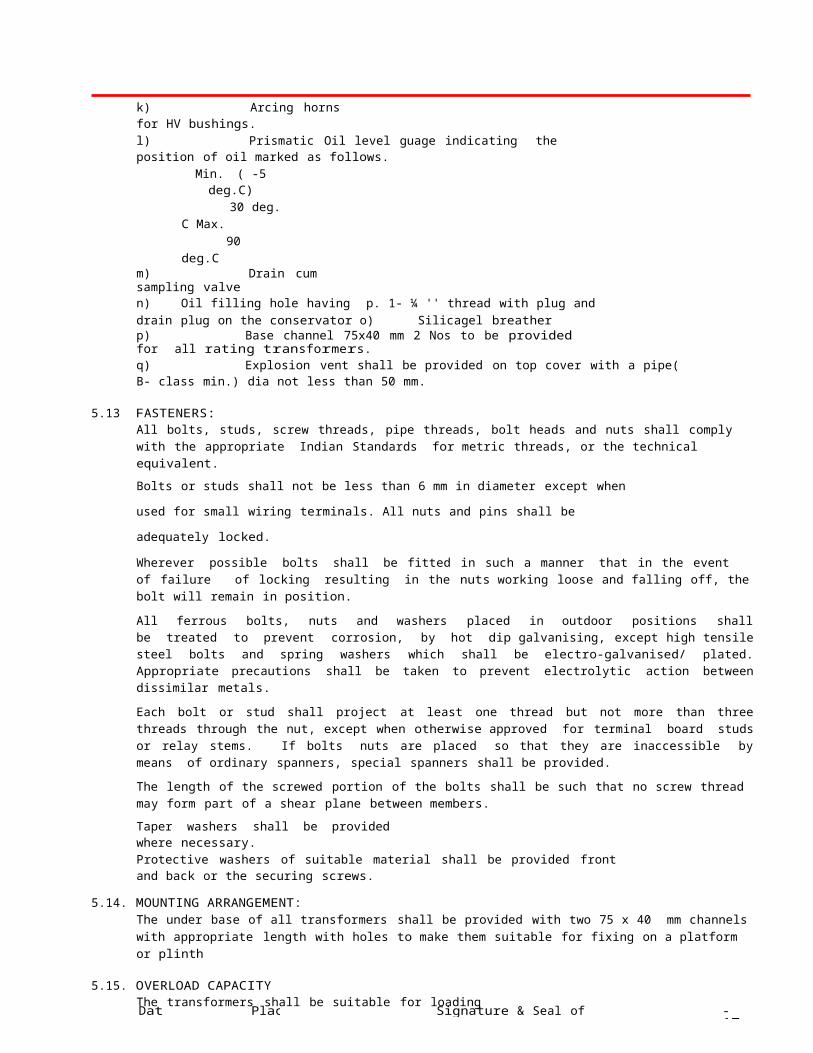
k) Arcing horns for HV bushings.l) Prismatic Oil level guage indicating the position of oil marked as follows.
Min. ( -5 deg.C)30 deg. C
Max. 90 deg.Cm) Drain cum sampling valven) Oil filling hole having p. 1- ¼ '' thread with plug and drain plug on the conservator o) Silicagel breatherp) Base channel 75x40 mm 2 Nos to be provided for all rating transformers.q) Explosion vent shall be provided on top cover with a pipe( B- class min.) dia not less than 50 mm.
5.13 FASTENERS:All bolts, studs, screw threads, pipe threads, bolt heads and nuts shall comply with the appropriate Indian Standards for metric threads, or the technical equivalent.
Bolts or studs shall not be less than 6 mm in diameter except when used for small wiring terminals.
All nuts and pins shall be adequately locked.
Wherever possible bolts shall be fitted in such a manner that in the event of failure of locking resulting in the nuts working loose and falling off, the bolt will remain in position.
All ferrous bolts, nuts and washers placed in outdoor positions shall be treated to prevent corrosion, by hot dip galvanising, except high tensile steel bolts and spring washers which shall be electro-galvanised/ plated. Appropriate precautions shall be taken to prevent electrolytic action between dissimilar metals.
Each bolt or stud shall project at least one thread but not more than three threads through the nut, except when otherwise approved for terminal board studs or relay stems. If bolts nuts are placed so that they are inaccessible by means of ordinary spanners, special spanners shall be provided.
The length of the screwed portion of the bolts shall be such that no screw thread may form part of a shear plane between members.
Taper washers shall be provided where necessary.Protective washers of suitable material shall be provided front and back or the securing screws.
5.14. MOUNTING ARRANGEMENT:The under base of all transformers shall be provided with two 75 x 40 mm channels with appropriate length with holes to make them suitable for fixing on a platform or plinth
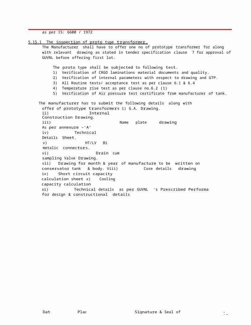
5.15. OVERLOAD CAPACITYThe transformers shall be suitable for loading as per IS: 6600 / 1972
5 . 1 5 . 1 T h e i n sp ec t i on o f p r o t o t y p e t r a n s f o r m e r . The Manufacturer shall have to offer one no of prototype transformer for along with relevant drawing as stated in tender specification clause 7 for approval of GUVNL before offering first lot.
The proto type shall be subjected to following test.1) Verification of CRGO laminations material documents and quality.2) Verification of internal parameters with respect to drawing and GTP.3) All Routine tests/ acceptance test as per clause 6.1 & 6.44) Temperature rise test as per clause no.6.2 (1)5) Verification of Air pressure test certificate from manufacturer of tank.
The manufacturer has to submit the following details along with offer of prototype transformers i) G.A. Drawing.ii) Internal Construction Drawing.iii) Name plate drawing As per annexure –‘A’iv) Technical Details Sheet.v) HT/LV Bi metalic connectors.vi) Drain cum sampling Valve Drawing.vii) Drawing for month & year of manufacture to be written on conservator tank & body. Viii) Core details drawingix) Short circuit capacity calculation sheet x) Cooling capacity calculationxi) Technical details as per GUVNL ‘s Prescribed Performa for design & constructional details

Date Place Signature & Seal of tenderer - 10 -
The tenderer shall submit their own drawings. The bidder shall submit above details along with offer.. However , offer without drawings shall not be considered Also each pages of technical bid & price bid shall be provided with seal of manufacturer & duly signed.
5.15.2 G U A R A N TE E F O R T H E T R A N S F O R M E R S ;1) Guarantee period shall be 60 months from the date of supply. If any transformer fails during this guarantee period, the
supplier shall repair the same at his cost at his works.
2) The supplier situated outside Gujarat State shall have to establish suitable and adequate arrangement for repairing and testing of failed transformer in Gujarat State at his cost. This arrangement shall have to be continued up to the completion date of guarantee period of supply of last lot.
3) After intimation of failure of transformer failed within guarantee period, GUVNL will arrange for the dispatch of guarantee period failed transformer to firm’s works at the cost of GUVNL. On receipt of guarantee period failed transformer at firm’s works, the external inspection will be carried out by the representative of GUVNL not below the rank of Junior Engineer. The cost of any outer component damage not because of supplier’s fault and required to be provided will be reimbursed to the supplier as per the approved rate of GUVNL on the strength of joint external inspection report. No. internal inspection of failed unit is to be carried out in presence of representative of GUVNL. However, the supplier may prepare an internal inspection report of failed unit for his study and analysis. If required, such analysis shall be furnished to GUVNL.
After joint inspection, the failed transformer shall be repaired within one month and the repaired unit duly tested shall be dispatched by supplier at his cost to the concerned consignee from where the failed unit was received along with the test report. If the transformer is not repaired and delivered back or dispatched without complete test report within this period, than the cost of GP failed transformer shall be recovered from the supplier’s pending / ensuing bill against the order or any other of order. In case, the supplier does not have further order, the cost of GP failed transformers shall be recovered from the Bank Guarantee furnished. Testing of transformer will be done in presence of Board’s Engineer to ensure no change in losses as per GTP after repair. Transformer found with higher losses than GTP will not be accepted and cost thereof will be recovered.
6.0. TESTS:a) All the equipment offered shall be fully type tested by the bidder or his collaborator as per the type tests mentioned at clause 6.2. The type test must have been conducted on a transformer of same design.b) Special tests other than type and routine tests, as agreed between purchaser and Bidder shall also be carried out as per the relevant standards.c) The requirements of site tests are also given in this clause.d) The test certificates for all routine and type tests for the transformers and also for the bushings and transformer oil shall be submitted.
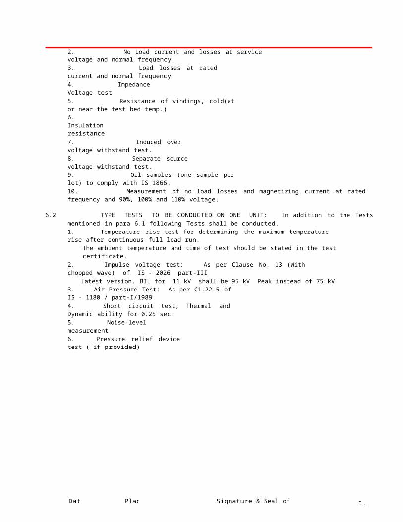
6.1. ROUTINE TESTS : Test certificate shall be submitted as per annexure-IV.1. Ratio, polarity and phase sequence.2. No Load current and losses at service voltage and normal frequency.3. Load losses at rated current and normal frequency.4. Impedance Voltage test5. Resistance of windings, cold(at or near the test bed temp.)6. Insulation resistance7. Induced over voltage withstand test.8. Separate source voltage withstand test.9. Oil samples (one sample per lot) to comply with IS 1866.10. Measurement of no load losses and magnetizing current at rated frequency and 90%, 100% and 110% voltage.
6.2 TYPE TESTS TO BE CONDUCTED ON ONE UNIT: In addition to the Tests mentioned in para 6.1 following Tests shall be conducted.1. Temperature rise test for determining the maximum temperature rise after continuous full load run.
The ambient temperature and time of test should be stated in the test certificate.2. Impulse voltage test: As per Clause No. 13 (With chopped wave) of IS - 2026 part-III
latest version. BIL for 11 kV shall be 95 kV Peak instead of 75 kV3. Air Pressure Test: As per C1.22.5 of IS - 1180 / part-I/19894. Short circuit test, Thermal and Dynamic ability for 0.25 sec.5. Noise-level measurement6. Pressure relief device test ( if provided)

Date Place Signature & Seal of tenderer - 11 -
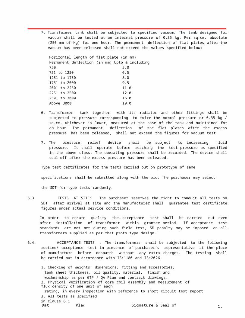
7. Transformer tank shall be subjected to specified vacuum. The tank designed for vacuum shall be tested at an internal pressure of 0.35 kg. Per sq.cm. absolute (250 mm of Hg) for one hour. The permanent deflection of flat plates after the vacuum has been released shall not exceed the values specified below:
Horizontal length of flat plate (in mm) Permanent deflection (in mm) Upto & including 750 5.0751 to 1250 6.51251 to 1750 8.01751 to 2000 9.52001 to 2250 11.02251 to 2500 12.02501 to 3000 16.0Above 3000 19.0
6. Transformer tank together with its radiator and other fittings shall be subjected to pressure corresponding to twice the normal pressure or 0.35 kg / sq.cm. whichever is lower, measured at the base of the tank and maintained for an hour. The permanent deflection of the flat plates after the excess pressure has been released, shall not exceed the figures for vacuum test.
7. The pressure relief device shall be subject to increasing fluid pressure. It shall operate before reaching the test pressure as specified in the above class. The operating pressure shall be recorded. The device shall seal-off after the excess pressure has been released.
Type test certificates for the tests carried out on prototype of same specifications shall be submitted along with the
bid. The purchaser may select the SDT for type tests randomly.
6.3. TESTS AT SITE: The purchaser reserves the right to conduct all tests on SDT after arrival at site and the manufacturer shall guarantee test certificate figures under actual service conditions.
In order to ensure quality the acceptance test shall be carried out even after installation of transformer within grantee period. If acceptance test standards are not met during such field test, 5% penalty may be imposed on all transformers supplied as per that proto type design.
6.4. ACCEPTANCE TESTS : The transformers shall be subjected to the following routine/ acceptance test in presence of purchaser’s representative at the place of manufacture before despatch without any extra charges. The testing shall be carried out in accordance with IS:1180 and IS:2026.
1. Checking of weights, dimensions, fitting and accessories, tank sheet thickness, oil quality, material, finish and workmanship as per GTP / QA Plan and contract drawings.
2. Physical verification of core coil assembly and measurement of flux density of one unit of eachrating, in every inspection with reference to short circuit test report
3. All tests as specified in clause 6.1
6.5 TOLERANCES: Unless otherwise specified herein the test value of the transformers supplied would be within the tolerance permitted in the relevant standards. No positive tolerance is allowed on guaranteed No Load and Load losses.
7.0. INSPECTION:All tests and inspection shall be made at the place of manufacturer and unless other wise especially agreed upon the manufacturer and the purchaser at the time of purchase. The manufacturer shall afford the inspector representing the purchaser all reasonable facilities, without charge to satisfy him that the material is being furnished in accordance with specification.
The manufacturer shall provide all services to establish and maintain quality of workman ship in his works and that of his sub-contractors to ensure the mechanical / electrical performance of components, compliance with drawings, identification and acceptability of all materials, parts and equipment as per latest quality standards of ISO 9000.
Along with the bid the manufacturer shall prepare Quality Assurance Plan identifying the various stages of manufacture, quality checks performed at each stage and the Customer hold points. The document shall also furnish details of method of checking, inspection and acceptance standards / values and get the approval of purchaser or his representative before proceeding with manufacturing. However, purchaser or his representative shall have the right to review the inspection reports, quality checks and results of manufacturer’s in house inspection department which are not customer hold points
Date Place Signature & Seal of tenderer - 12 -
and the manufacturer shall comply with the remarks made by purchaser or his representative on such reviews with regards to further testing, rectification or rejection etc. Manufacturer should submit the list of equipment for testing along with latest calibration certificates to the purchaser.
Purchaser shall have every right to appoint a third party inspection to carryout the inspection process. The purchaser has the right to have the test carried out at his own cost by an independent agency wherever the dispute regarding the quality of supply. Purchaser has right to test 1% of the supply selected either from the stores or field to check the quality of the product. In case of any deviation purchaser have every right to reject the entire lot or penalize the manufacturer, which may leads to blacklisting among other things.
8.0. QUALITY ASSURANCE PLAN:8.1. The Bidder shall invariably furnish following information along with his bid, failing which his bid shall be liable for
rejection. Information shall be separately given for individual type of equipment offered.
i. Statement giving list of important raw materials, names of sub-suppliers for the raw materials, list of standards according to which the raw materials are tested. List of tests normally carried out on raw materials in the presence of Bidder’s representative, copies of test certificates.
ii. Information and copies of test certificates as in (I) above in respect of bought out accessories.iii. List of manufacturing facilities available.iv. Level of automation achieved and list of areas where manual processing exists.v. List of areas in manufacturing process, where stage inspections are normally carried out for quality control and
details of such tests and inspection.vi. List of testing equipment available with the bidder for final testing of equipment along with valid calibration
reports shall be furnished with the bid. Manufacturer shall posses 0.1 class instruments for measurement of losses.
vii. Quality Assurance Plan (QAP) with hold points for purchaser’s inspection as per Annexure.
8.2 The successful Bidder shall within 30 days of placement of order, submit following information to the purchaser.i. List of raw materials as well as bought out accessories and the names of sub-suppliers selected
from those furnished along with offer.ii. Type test certificates of the raw materials and bought out accessories.
8.3 The successful Bidder shall submit the routine test certificates of bought out accessories and central excise passes for raw material at the time of routine testing.
9.0. DOCUMENTATION:The Bidder shall furnish along with the bid the dimensional drawings of the items offered indicating all the fittings. i) Dimensional tolerancesii) weight of individual components and total weight
10.0 PACKING & FORWARDING:10.1 The packing shall be done as per the manufacturer’s standard practice. However, it should be ensured that the packing is
such that, the material would not get damaged during transit by Rail / Road / Sea.10.2 The making on each package shall be as per the relevant IS.
11.0 MANADATORY SPARES:Mandatory spares shall be supplied as per the purchaser’s requirement.
12.0 CHALLANGE TESTING:The other manufacturer can also request challenge testing for any test based on specification and losses. The challenger would request for testing with testing fee. The challenge test fees are proposed at least three time the cost of testing .This is likely to deter un necessary challenges. The challenger would have the opportunity to select the sample from the store and any such challenge should be made within the guaranty period. The party challenged, challanger and the utility could witness the challenged testing. The challenged testing would cover the 1) Measurement of magnetizing current. 2) No load losses test. 3) Load losses test (at 50% loading or as per acceptance test). 4) Temperature rise test.The challenge test could be conducted at NABL accredited laboratory, like ERDA and CPRI Bhopal. If the values are within limit the product gets confirmed else not confirmed. No positive tolerance in losses be permitted. If the product is not confirmed the manufacturer would pay the challenge fee and challenger would get the fee refunded. However as a redressal system the challenger would be allowed to ask for fresh testing of two more samples from the store and the same be tested in NABL laboratory in presence of party challenged,challanger and the utility. If any one or both sample does not confirm the test then the product is said to have failed the test. In such cases the manufacturer will be declared
Date Place Signature & Seal of tenderer - 13 -
as un successful manufacturer for the said product with wide publicity and would not be allowed to compete in tenders of the Board for the period of three years and heavy penalty would be imposed.
13.0. Drawings:One copy of the dimensional drawing and internal construction drawing of each ratting transformer shall be submitted with the tender. These drawings shall be of A-3(420 x 297 mm) size only. Format and pattern of the drawings shall be as per specimen drawing attached with the tender specification. Guaranteed and other technical particulars of the transformers as per the A/T shall also be submitted in A-4 size for our approval. In thePerforma attached with tender only.
14 . 0 G T P- . G u a r a n t e e d a n d o t h e r p a r t i c u l a r s f o r t r a n s f o r m e r s . To be filled in and submitted by the tenderer in the Performa attached with the tender.
15.0 . S c h e du l e :
15.1 The tenderer shall fill in the following Schedules which from part of the tender specification and offer. In schedule ‘A’ the specific values shall be furnished and only quoting of IS reference is not sufficient. If the schedule are not submitted duly filled in with the offer, the offer shall be liable for rejection.
Schedule ‘A’ Guaranteed Technical Particulars (Annexure- I,II & III). Schedule ‘B’ Schedule of Deviations from Specification.Schedule ‘C’ Schedule of Tenderer’s Experience.Schedule ‘D’ Schedule of Deviation from specified standards.Schedule ‘E’ Schedule of Deviations from specified Test requirements.
15.2. All deviations from the specifications shall be brought out in the schedules of deviation (Schedules ‘B’,’D’ & ‘E’). The discrepancies between the specification and the catalogues, literatures and indicative drawings which are subject to change, submitted as part of the offer, shall not be considered and representation in this regard will not be entertained. If it is observed that there are deviations in the offer in G.T.P. of elsewhere other than those specified in the deviation schedule‘B’ then such deviations shall be treated as deviations.
15.3. For any deviation from the specification, which is not specifically brought out in the schedule of deviations, the offer may be liable for rejection. The deviation brought out in the schedule shall be supported by authentic documents, standards and clarifications, otherwise the offer may be liable for rejection.
15.4. The tenderer shall submit the list of orders for similar type of equipments, executed of under execution during the last three years, with full details in the schedule of Tender’s experience (Schedule ‘C’) to enable the purchaser to evaluate the tender.
15.0 T e n d e r D r a w i n g s t o be e n c l o s e d :i) G.A. Drawing.ii) Internal Construction Drawing. iii) Name plate drawingiv) Technical Details Sheet. v) HT Bimetalic connectors.vi) Drain cum sampling Valve Drawing.vii) Drawing for month & year to be written on conservator tank & body. Viii) Core details drawingix) short circuit capacity calculation sheet x) cooling capacity calculation
The Tenderer shall submit their own drawings. The bidder shall submit above details along with offer as well as before offering the prototype transformer.
16. AUDIT INSPECTION:After inspection of ordered transformer by the User Department Inspector, field engineer may pick up samples from the lots supplied at RSOs/Power Stations Stores/ or other stores of the Board or from the works of party, for quality check at random. The samples picked up will be tested for Acceptance Test / Type Tests or the tests as decided by Board, at Government approved laboratory, in presence of representatives of supplier and GUVNL, as per relevant ISS/BIS/GUVNL Specification and GTP, as under:
(i) One number of each rating of transformer shall be picked up at random by field engineer from RSO’s / Power StationStores and will be tested for Acceptance Tests & Temperature Rise Test.
Date Place Signature & Seal of tenderer - 14 -
(ii) One number of each rating of transformer sealed at party’s works by field engineer will be tested for (a) Impulse Test (b) Short Circuit Test (c) other Type Tests(if decided by the company).
As regard bearing test charges, for transformers picked up for testing from RSOs/Power Station Stores, GUVNL will bear total expenses. However, for witnessing the tests, successful tenderer shall have to bear their own expenses.
For transformers sealed at party’s works for Type Tests, if sample passes in all tests, GUVNL will bear only testing charges.
However, if sample fails in any of the tests, cost of testing charges including transportation, loading unloading etc. will have to bepaid by supplier. Alternatively, it will be recovered from supplier’s bills.
In case, if the materials do not conform to specifications or fails at Government approved laboratory or other laboratory decided by UGVCL for testing and if subsequent testings are to be carried out (which will solely at UGVCL’s discretion), all Testing fees, expenses of the inspector & other expenses incurred by UGVCL will be to successful tenderer’s account. For acceptance as above, the decision of UGVCL shall be final & will be binding to successful tenderer.
The test results will be binding on the suppliers. UGVCL in general w il l n o t all ow r e - s a m p l i ng . If the material fails in any of the acceptance tests carried out (except for no load and load losses), the materials supplied till date will be considered as rejected and if replacement is not possible due to consumption of the materials, UGVCL will deduct penalty @ 5% of the end cost prices of all transformers supplied till date of receipt of failure report. If the same are not utilized / consumed, UGVCL at sole discretion may ask for replacement or may accept the material with penalty as above. For failure in No Load and or Load Losses, transformers supplied till date of receipt of failure report shall be rejected or penalty @ Rs.395.00 per watt for No Load Losses and penalty @ Rs.79.00 per watt for Load Losses for the transformers supplied till date of receipt of failure report shall be charged. The decision of UGVCL will be binding on the successful tenderer.
In the event of transformer failing during any of the type tests (temperature rise test is part of type test), following recovery shall be made.
Recovery, equivalent to 1% of end cost of particular rating transformers supplied against the order till receipt of test reports.
Further in case, any transformer taken for type testing, fails either in short circuit test or impulse test or temp. rise test, or other type tests (if decided by UGVCL), supplier will be allowed for modification in their design and other technical parameters. In that case, supplier will have to obtain prior approval from UGVCL/GUVNL for such proposed changes / modifications desired to be effected, by submitting revised drawings and other technical details, clearly indicating the changes proposed to be made, compared to previous design.
In case, if transformers shall fail in testing and same are rejected or accepted with penalty, UGVCL shall pick up another transformer for Acceptance Tests / Type Tests (as the case may be) of same rating from replaced and or subsequently supplied lots for testing to have verification of the quality of other transformers supplied.
In case of any dispute for testing, the UGVCL’s decision will be final and binding to the supplier. If supplier will not agree to accept the UGVCL’s decision, the order for balance quantity will be cancelled without any clarification and material will be purchased by the UGVCL at risk and cost of the supplier.
The minimum lot to be offered for inspection shall be as under:
At least 33% of each rating or as mentioned in delivery schedule of the order, whichever is less, for the ordered quantity up to100Nos.
ii) Minimum 50 Nos. of each rating or as mentioned in delivery schedule of the order, whichever is less, for the ordered quantity above 100 Nos.
SEAL & SIGNATURE OF THE TENDERER
Date Place Signature & Seal of tenderer - 15 -
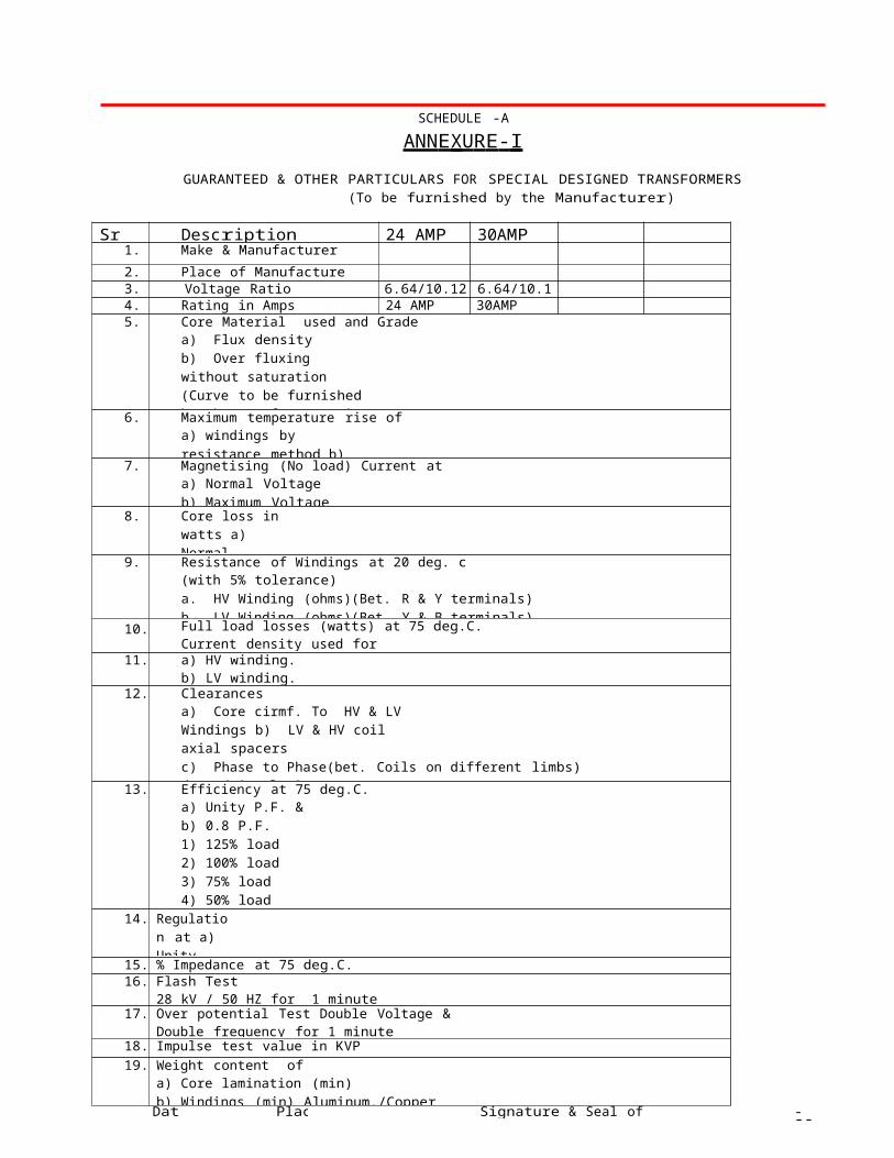
SCHEDULE -A
ANN E XU R E - I
GUARANTEED & OTHER PARTICULARS FOR SPECIAL DESIGNED TRANSFORMERS (To be furnished by the Manufacturer)
Sr No Description 24 AMP 30AMP1. Make & Manufacturer
2. Place of Manufacture3. Voltage Ratio 6.64/10.12kv 6.64/10.12kv4. Rating in Amps 24 AMP 30AMP5. Core Material used and Grade
a) Flux densityb) Over fluxing without saturation (Curve to be furnished by the Manufacturer in supportof his claim)
6. Maximum temperature rise ofa) windings by resistance method b) Oil by Thermometer
7. Magnetising (No load) Current ata) Normal Voltageb) Maximum Voltage
8. Core loss in watts a) Normal Voltageb) Maximum Voltage
9. Resistance of Windings at 20 deg. c(with 5% tolerance)a. HV Winding (ohms)(Bet. R & Y terminals)b. LV Winding (ohms)(Bet. Y & B terminals)
10. Full load losses (watts) at 75 deg.C.Current density used for
11. a) HV winding.b) LV winding.
12. Clearancesa) Core cirmf. To HV & LV Windings b) LV & HV coil axial spacersc) Phase to Phase(bet. Coils on different limbs)d) End insulation clearance to Earth
e) Any point of winding to tank13. Efficiency at 75 deg.C.
a) Unity P.F. &b) 0.8 P.F.1) 125% load2) 100% load3) 75% load4) 50% load5) 25% load
14. Regulation at a) Unity P.F.b) 0.8 P.F. at 75 deg.C.
15. % Impedance at 75 deg.C.16. Flash Test
28 kV / 50 HZ for 1 minute17. Over potential Test Double Voltage &
Double frequency for 1 minute18. Impulse test value in KVP
19. Weight content ofa) Core lamination (min)b) Windings (min) Aluminum./Copper
Date Place Signature & Seal of tenderer - 16 -
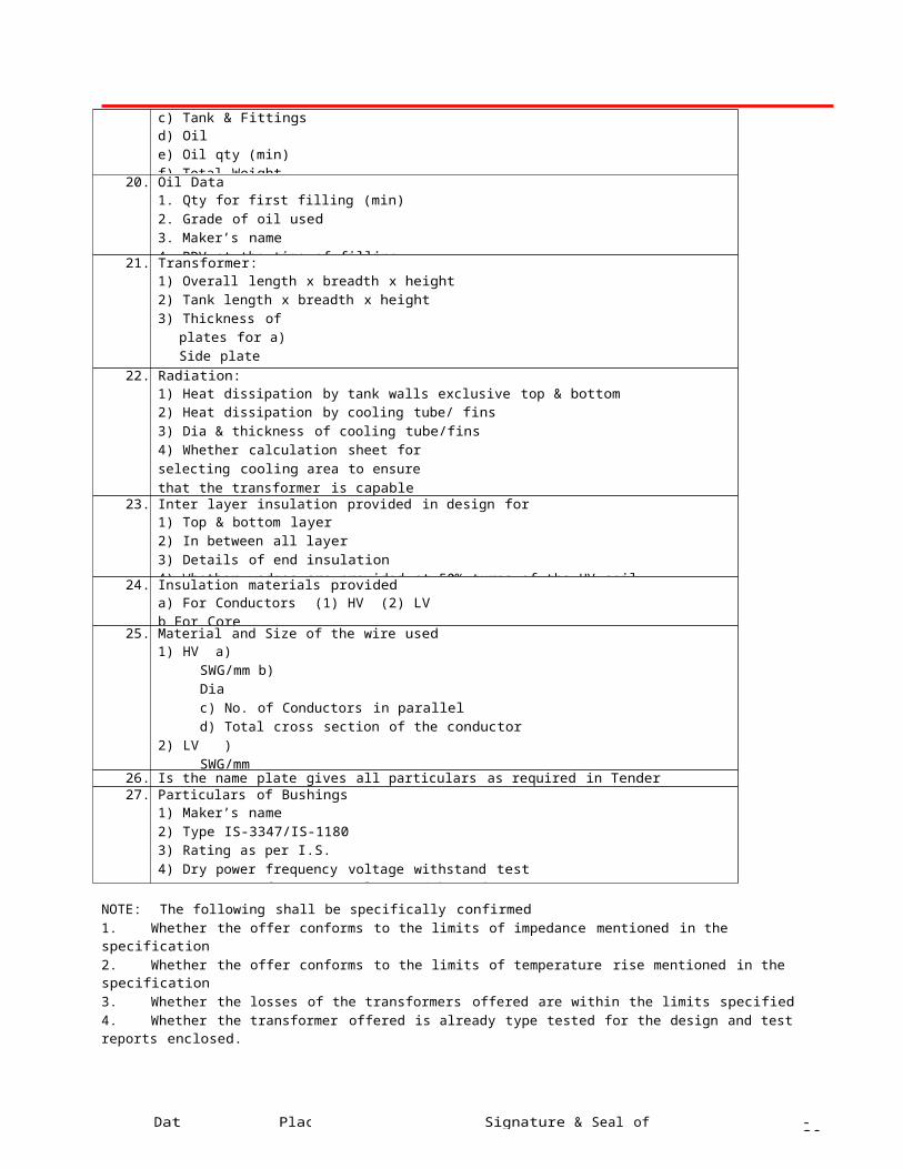
c) Tank & Fittingsd) Oile) Oil qty (min)f) Total Weight
20. Oil Data1. Qty for first filling (min)2. Grade of oil used3. Maker’s name4. BDV at the time of filling
21. Transformer:1) Overall length x breadth x height2) Tank length x breadth x height3) Thickness of plates for
a) Side plate (min)b) Top & Bottom plate (min)
4) Conservator Dimensions22. Radiation:
1) Heat dissipation by tank walls exclusive top & bottom2) Heat dissipation by cooling tube/ fins3) Dia & thickness of cooling tube/fins4) Whether calculation sheet for selecting cooling area to ensure that the transformer is capableof giving continuous rated output without exceedingtemperature rise is enclosed.
23. Inter layer insulation provided in design for1) Top & bottom layer2) In between all layer3) Details of end insulation4) Whether wedges are provided at 50% turns of the HV coil
24. Insulation materials provideda) For Conductors (1) HV (2) LVb For Core
25. Material and Size of the wire used1) HV a) SWG/mm
b) Diac) No. of Conductors in paralleld) Total cross section of the conductor
2) LV ) SWG/mm b) Diac) No. of Conductors in paralleld) Total cross section of the conductor
26. Is the name plate gives all particulars as required in Tender27. Particulars of Bushings
1) Maker’s name2) Type IS-3347/IS-11803) Rating as per I.S.4) Dry power frequency voltage withstand test5) Wet power frequency voltage withstand test
NOTE: The following shall be specifically confirmed1. Whether the offer conforms to the limits of impedance mentioned in the specification2. Whether the offer conforms to the limits of temperature rise mentioned in the specification3. Whether the losses of the transformers offered are within the limits specified4. Whether the transformer offered is already type tested for the design and test reports enclosed.
SEAL & SIGNATURE OF THE TENDERER
Date Place Signature & Seal of tenderer - 17 -
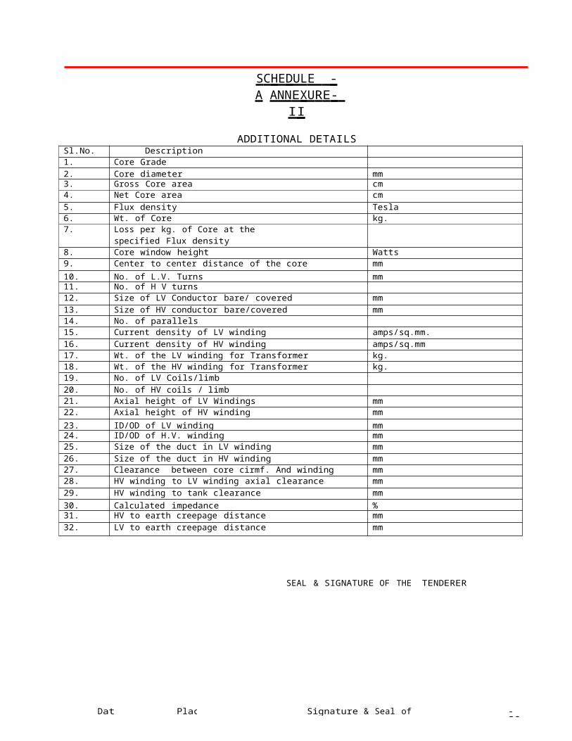
S C H E DUL E - A ANN E XU R E - I I
ADDITIONAL DETAILSSl.No. Description1. Core Grade2. Core diameter mm3. Gross Core area cm4. Net Core area cm
5. Flux density Tesla6. Wt. of Core kg.7. Loss per kg. of Core at the
specified Flux density
8. Core window height Watts9. Center to center distance of the core mm
10. No. of L.V. Turns mm11. No. of H V turns12. Size of LV Conductor bare/ covered mm
13. Size of HV conductor bare/covered mm14. No. of parallels15. Current density of LV winding amps/sq.mm.
16. Current density of HV winding amps/sq.mm17. Wt. of the LV winding for Transformer kg.18. Wt. of the HV winding for Transformer kg.19. No. of LV Coils/limb
20. No. of HV coils / limb21. Axial height of LV Windings mm22. Axial height of HV winding mm
23. ID/OD of LV winding mm24. ID/OD of H.V. winding mm25. Size of the duct in LV winding mm
26. Size of the duct in HV winding mm27. Clearance between core cirmf. And winding mm28. HV winding to LV winding axial clearance mm
29. HV winding to tank clearance mm30. Calculated impedance %31. HV to earth creepage distance mm
32. LV to earth creepage distance mm
SEAL & SIGNATURE OF THE TENDERER
Date Place Signature & Seal of tenderer - 18 -
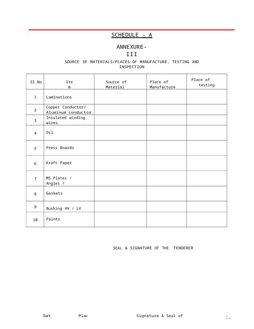
S C H E DUL E - A
ANNEXURE-IIISOURCE OF MATERIALS/PLACES OF MANUFACTURE, TESTING AND INSPECTION
Sl.No. Item Source of Material Place of ManufacturePlace of testing and
inspection
1 Laminations
2Copper Conductor/Aluminum conductor
3Insulated winding wires
4 Oil
5 Press Boards
6 Kraft Paper
7 MS Plates / Angles / Channels
8 Gaskets
9 Bushing HV / LV
10 Paints
SEAL & SIGNATURE OF THE TENDERER

Date Place Signature & Seal of tenderer - 19 -
SCHEDULE-B
DEVIATIONS FROM SPECIFICATION
---------------------------------------------------------------------------------------------------------------- SR.NO. CLAUSE NO. DETAILS OF DEVIATION----------------------------------------------------------------------------------------------------------------
NAME OF FIRM-----------------------------------------------
NAME & SIGNATUREOF TENDERER ---------------------------------------
DESIGNATION -----------------------------------------------
DATE -----------------------------------------------------------
Date Place Signature & Seal of tenderer - 20 -
SCHEDULE - C
SCHEDULE OF TENDERER’S EXPERIENCEJob nos and name of division of LSTs converted has aslo to be stated.
----------------------------------------------------------------------------------------------------------------Sr. Name of Client Value of Period of supply Name & address to whomNo. & Description order along- and commissioning reference may be made
with cap. oftransformer
--------------------------------------------------------------------------------------------------------------------------1 2 3 4 5--------------------------------------------------------------------------------------------------------------------------
NAME OF FIRM
NAME & SIGNATUREOF TENDERER
DESIGNATION
DATE
Date Place Signature & Seal of tenderer - 21 -
SCHEDULE - D
SCHEDULE OF DEVIATION FROM SPECIFIED STANDARDS
------------------------------------------------------------------------------------------------------- Sr. Particulars Stipulation of Stipulation of RemarksNo. specified stan- standard adopted
dards by tenderers-------------------- ----------------------- Standard Stipul- Standard Stipula- Ref. ations Ref. tions
-------------------------------------------------------------------------------------------------------
NAME OF FIRM _
NAME & SIGNATUROF TENDERER
DESIGNATION
DATE

Date Place Signature & Seal of tenderer - 22 -
SCHEDULE - E
DEVIATION FROM SPECIFIED TEST REQUIREMENTS SPECIFIED IN RELEVANT AND PRESENT SPECIFICATIONS.
---------------------------------------------------------------------------------------------------------------------------- Sr. Name of Test Standard Requirement Proposed Reason forNo. No. and of standards deviation deviation
clause no.----------------------------------------------------------------------------------------------------------------
1. TYPE TEST
2. ADDITIONAL TEST
3. ACCEPTANCE TEST
4. ROUTINE TEST
NAME OF FIRM
NAME & SIGNATUREOF TENDERER _
DESIGNATION
DATE

Date Place Signature & Seal of tenderer - 23 -
Q UAL I T Y A SS U R AN C E P L A N F O R SP E CI A L DE S I GNE D T R AN S F O R M E R S
S c o p e a n d P u r p o s e :
This document indicates the requirement expected by the Purchaser from the manufacturer of SDT Manufacturer shall submit for purchaser’s approval a quality assurance plan in line with this document incorporating specific document numbers for “format of records”, “acceptance norms” and “ reference documents” for purchaser’s approval.
Quality assurance plan is the document setting out the specific quality practices, resources, and sequence of activities relevant to a particular product. Quality plan helps both the purchaser and supplier as it defines each and every material used, every stage of manufacturing process, characteristics to be checked, extent of check, reference documents, acceptance norm and format of record specifically.
A b br e v iati on s : PS - Plant Standard / Process Specification
TR - Test Report
IS - Indian/ International Standard
CS - Customer Specification
AD - Approved Document such as Drawing, Purchase Order
V - Verified by
P - Performed by
W - Witnessed by
H - Hold by Purchaser
1 - Purchaser
2 - Manufacturer
3 - External laboratory
4 - Sub Vendor QC
N ot e s : 1. M i n o r : The characteristics of a component, process or operation whose failure neither
materially reduce the usability of the product in operation, nor does it affect the aesthetic aspects.
2. M aj or: The characteristics of a component, process, or operation whose failure may cause operation failure
which cannot be readily corrected, at site cause substandard performance, increase erection and maintenance cost, reduce
life or seriously affect aesthetics.
3. Cr i t ica l : The characteristic of a component, process, or operation failure of which will surely cause operating
failure or intermittent troubles which is difficult to rectify at site or render the unit unfit for use or safety hazards.
4. “F a i l ur e ” of a characteristic means failure to meet the ‘accepted norms’
5. S am p li n g : Generally sampling will be done in accordance with IS: 2500. Sampling will be as under:-
If 100% “Witness” of tests is carried out by Prime supplier, Customer will witness on sample basis or if 100% “Witness” of tests is carried out by Sub Vendor, Manufacturer will witness on sample basis.
Date Signature & Seal of tenderer - 24 -
Q UA L I T Y A SS URANCE P L AN F O R S P E C I AL D ES I G N E D T RA N S F O R M E RS
SL.
NO
COMPONENT &
OPERATIONS
CHARACTERISTICS CLASS TYPE OF
CHECK
QUANTUM
OF CHECK
REFERENCE
DOCUMENT
ACCEPTANCE
NORMS
FORMAT OF
RECORD
AGENCY REMARKS
V P W H
1 2 3 4 5 6 7 8 9 10 11
RAW M A T ER I A L S
1. CRGO coils /
Amorphous ribbons
Dimensions Major Measurement 100 %
Specific losses Major Measurement 100 %
Chemical Analysis Major Measurement Sample / lot
Surface Insulation Resistance Major Measurement 100%
Transit Damages Major Visual 100 %
Stacking Factor Major Measurement 100 %
2. Copper Wire Rods Tensile strength Major Measurement 100 %
Elongation Major Measurement 100 %
Dimensions Major Measurement 100 %
Transit damages Major Visual 100 %
Cracks & twists Major Visual 100 %
Resistivity Major Measurement 100 %
Chemical Analysis Major Measurement one sample/Consignment
3. Kraft Paper Transit Damages & PackingCondition
Major Visual 100 %
Dimensions Major Measurement 10 % of lot
Density Major Measurement 100 %
Tensile Strength Major Measurement 100 %
Elongation Major Measurement 100 %
Date Signature & Seal of tenderer - 25 -
SL.NO
COMPONENT &
OPERATIONS
CHARACTERISTICS CLASS TYPE OF
CHECK
QUANTUM
OF CHECK
REFERENCE
DOCUMENT
ACCEPTANCE
NORMS
FORMAT OF
RECORD
AGENCY REMARKS
V P W H
1 2 3 4 5 6 7 8 9 10 11
Moisture content Major Measurement 100 %
Ash Content Major Measurement 100 %
Dielectric strength Major Measurement 2 samples /lot
4. Epoxy dotted Kraftpaper
Transit Damages & PackingCondition
Major Visual 100 %
Dimensions Major Measurement 10 % of lot
Density Major Measurement 100 %
Tensile Strength Major Measurement 100 %
Elongation Major Measurement 100 %
Moisture content Major Measurement 100 %
Ash Content Major Measurement 100 %
Dielectric strength Major Measurement 2 samples /lot
Thickness of resin coating Major Measurement sample / lot
5. Insulating Oil Appearance Major Measurement Sample from eachtanker
Density at 27°C Major Measurement -do-
Viscosity at 27°C Major Measurement -do-
Interfacial Tension at 27°C Major Measurement -do-
Flash Point Major Measurement -do-
Pour Point Major Measurement -do-
Total Acidity Major Measurement -do-
Corrosion Sulpher copperstrip.19 hrs @ 140°C
Major Test -do-
BDV Major Measurement -do-
Dielectric dissipation factor@ 90°C
Major Measurement -do-
Specific resistancea) at 27°Cb) at 90°C
Major Measurement -do-
Oxidation stability Major Measurement -do-
Accelerated aging test Major Test -do-
Date Signature & Seal of tenderer - 26 -
SL.NO
COMPONENT & OPERATIONS
CHARACTERISTICS CLASS TYPE OF CHECK
QUANTUM OF CHECK
REFERENCE DOCUMENT
ACCEPTANCE NORMS
FORMAT OF RECORD
AGENCY REMARKSV P W H
1 2 3 4 5 6 7 8 9 10 11Presence of oxidationinhibitor
Major Measurement Sample fromEach tanker
Water content Major Measurement -do-
6. Insulating PressBoard
Finish Appearance Major Visual 10 % of lotDimensions Major Measurement 10 % of lotDensity Major Measurement Sample /lotTensile Strength Major Measurement Sample /lotBDV Major Measurement Sample /lotAsh content Major Measurement Sample /lotMoisture content Major Measurement Sample /lotConductivity of aqueousextracts
Major Measurement Sample /lot
7. Perma Wood Finish appearance Major Visual 10 % of lotDimensions Major Measurement 10 % of lotElectric Strength Major Measurement Sample /lotDensity Major Measurement Sample /lotTensile Strength Major Measurement Sample /lotCross breaking strength Major Measurement Sample /lotImpact strength Major Measurement Sample /lotCompressive strength Major Measurement Sample /lotShear strength Major Measurement Sample /lotMoisture content Major Measurement Sample /lotOil absorption Major Measurement Sample /lot
8. Paper CoveredConductor
Finish Appearance Major Visual 100 %
Dimensions Major Measurement Each bobbinResistivity Major Measurement Sample /lotTensile Strength Major Measurement Sample / lotElongation Major Measurement Sample/ lot
Covering Thickness Major Measurement Each bobbin
Date Signature & Seal of tenderer - 27 -
SL.NO
COMPONENT & OPERATIONS
CHARACTERISTICS CLASS TYPE OF CHECK
QUANTUM OF CHECK
REFERENCE DOCUMENT
ACCEPTANCE NORMS
FORMAT OF RECORD
AGENCY REMARKSV P W H
1 2 3 4 5 6 7 8 9 10 11
9. Enamel Covered
Conductor
Finish Appearance Major Visual Each bobbin
Dimensions Major Measurement Each bobbin
Resistivity Major Measurement Sample /lot
Tensile Strength Major Measurement Sample /lot
Elongation Major Measurement 10 %
Covering Thickness Major Measurement Each bobbin
Flexibility Test Major Test 40 %
Adherence Major Test 40 %
Heat Shock Major Test 40 %
Hardness Major Measurement 40 %
Solvent Resistance Major Test Sample /lot
BDV Major Measurement 40 %
Cut-through Test Major Test Sample /lot
10. MS material
(Plates, Flats,
Angles &
channels)
Finish Appearance Major Visual 100 %
Dimension Major Measurement 2 % of lot
Hardness Major Measurement Sample / lot
Chemical composition Major Measurement Sample / lot
Tensile strength Major Measurement Sample / lot
Yield strength Major Measurement Sample / lot
Elongation Major Measurement Sample / lot
Bend test Major Test Sample / lot
11. Hard Ware Dimensions Major Measurement Sampling
Finish appearance Major Visual Sampling
11. Gaskets Finish appearance Major Visual 5%
Dimensions Major Measurement 5%
Compressibility Major Measurement Sample / lot
Tensile Strength Major Measurement Sample / lot
Recovery % Major Measurement Sample / lot
Oil immersion test Major Measurement Sample / lotCompressionset % at
110°CMajor Measurement Sample / lot
13 . Bushing
a) Porcelain Finish appearance Major Visual 100 %
Dimensions Major Measurement 10% of lot
Date Signature & Seal of tenderer - 28 -
b) Metal Parts
Power frequencywithstand test
Major Test 5 Nos / lot
Porasity test Major Test 5 Nos / lot
Temperature cycle test Major Test 5 Nos / lot
Finish appearance Major Visual 5% of lot
Dimensions Major Measurement 5% of lot
14. Plating/
Galvanizing/
Phosphating
Finish appearance Major Visual 2% of lot
Thickness of coating Major Measurement 2% of lot
15. Epoxy resin Appearance Major Visual Sample / lot
Viscosity Major Measurement Sample / lot
16. Paints
a) Primer
b) Hot oil resistance
Paint
c) Enamel Paint
d) Thermo setting
Powder Paint
Appearance Major Visual 100 %
Shade Major Visual 100 %
Viscosity Major Measurement Sample / lot
Shade Major Visual 100 %
Scratch Hardness Major Test Sample / lot
Drying time Major Measurement Sample / lot
Appearance Major Visual 100 %
Viscosity Major Measurement Sample / lot
Shade Major Visual 100 %
Drying time Major Measurement Sample / lot
Finish Major Visual 100 %
Scratch Hardness Major Test sample / lot
Flexibility & adhesion Major Test Sample / lot
Shade Major Visual 100%
Pencil Hardness Major Test Sample / lot
Cross Hatch Adhesion Major Test Sample / lot
Curing Cycle Major Measurement Sample / lot
17. HV & LV
connectors
Finish appearance Major Visual 100%Dimensions Major Measurement 5 % of lot
Chemical Composition Major Test 1 No. / lot
18. Oil level Gauge Finish Appearance Major Visual 10%
Dimensions Major Measurement 10 %
19. Silicagel Breather Gel weight Major Measurement 10 %
Gel Colour Major Visual 100%
Dimensions Major Measurement 10 %
Date Signature & Seal of tenderer - 29 -
M A NU F A C T URI N G P ROCE S S & A SS E M B L Y:
1. Transformer tank, Conservator &
accessories
Check of Raw material Major Visual 100 %
Cutting of material as per given drawing
Major Measurement Sampling
Finish dimensions & completeness as per
drawingMajor Measurement Sampling
Conservator tank and tube Dimensions
Major Measurement Sampling
Finish of weld Major Visual Sampling
Finish of material after gas cutting and welding
Major Visual 100 %
Leak test Major Test 100 %
Vacuum test Major TestOne/Each
Rating
Surface finish prior to paint application
Major Visual 100 %
Check of inside painting Major Visual 100 %
Application of Primer coating
Major Visual 100 %
Application of first coat of paint
Major Visual 100 %
Application of finish coat of paint
Major Visual 100 %
Date Signature & Seal of tenderer - 30 -
SL.
NO
COMPONENT &
OPERATIONS
CHARACTERISTICS CLASS TYPE OF
CHECK
QUANTUM
OF CHECK
REFERENCE
DOCUMENT
ACCEPTANCE
NORMS
FORMAT OF
RECORD
AGENCYREMA RKS
V P W H1 2 3 4 5 6 7 8 9 10 11
Paint thickness Major Measurement 100 %Adhesion Major Test 10 %Hardness Major Test 10 %
2. Frames & Channels welding
Check of raw material Major Visual 100 %Dimensions Major Measurement SamplingWeld finish Major Visual Sampling
Surface Preparation Major Visual 100%Painting Major Visual 100 %
3. Core Assembly
a) Core Cutting
b) Core Annealing c) Core assembly
Width Major Measurement Sampling
Thickness Major Measurement Sampling
Length Major Measurement Sampling
Burr Major Measurement Sampling
Angle of Cutting Major Measurement Sampling
Temperature & Speed Major Measurement Every one hourFormation of core section Major Measurement 100 %
Core dia Major Measurement 100 %
Stack thickness Major Measurement 100 %
Leg length Major Measurement 100 %Window width Major Measurement 100 %
Core weight Major Measurement 100 %
Binding of limbs Major Visual 100 %
Assembly of frame structure Major Visual 100 %
Pre-Core Losses Major Measurement Sampling
4. Winding Conductor Size Major Measurement 100 %
Former diameter Major Measurement 100 %
Coil dimensions ( ID, OD, AH,RD)
Major Measurement 100 %
Insulation arrangement Major Visual 100 %
Turns arrangement Major Visual 100 %
Date Signature & Seal of tenderer - 31 -
SL.NO
COMPONENT & OPERATIONS
CHARACTERISTICS CLASS TYPE OF CHECK
QUANTUM OF CHECK
REFERENCE DOCUMENT
ACCEPTANCE NORMS
FORMAT OF RECORD
AGENCY REMARKSV P W H
1 2 3 4 5 6 7 8 9 10 11
Transposition Major Visual 100 %
Finishing and lead position Major Visual 100 %
5. InsulationComponents
Dimensions Major Measurement SamplingFinishing Major Visual 100 %
6. Core & Coil
assembly
Dimensions Major Measurement 100 %Axial and Radial Insulation
arrangementMajor Measurement 100 %
Electrical clearances Major Measurement 100 %
Yoke filling Major Visual 100 %Position of lead out Major Visual 100 %
HV & LV connections Major Visual 100 %
Insulation and finishing of brazed / crimped joints
Major Visual 100 %
Ratio test Major Test 100 %
7. Drying of core coil
assembly
Temperature Major Measurement 100 %
Time duration Major Measurement 100 %Insulation Resistance Major Measurement 100 %
8. Tanking & Oil
filling under vacuum
Clamping of CCA Major Visual 100 %
Job locking Major Mechanical 100 %
Completeness Major Visual 100 %Dimensions Major Measurement 100 %
Electrical clearances Major Measurement 100 %
Breaker Operation Major Visual 100 %Vacuum Major Measurement 100 %
Oil temperature Major Measurement 100 %Fixing of accessories &fittings as per drawing
Major Visual 100 %
Leak proofness Major Pressure test Sampling
Date Signature & Seal of tenderer - 32 -
Sl.NO
COMPONENT &OPERATIONS
CHARACTERISTICS CLASS TYPE OFCHECK
QUANTUMOF CHECK
REFERENCEDOCUMENT
ACCEPTANCENORMS
FORMAT OFRECORD
AGENCY REMARKSV P W H
1 2 3 4 5 6 7 8 9 10 11
01.
IN S PECTI O N & TE S T I N G
ROUTINE TESTSa. WindingsResistance
Critical Measurement 100 % IS 2026 IS 2026 TC 1 2 1
b. Voltage Ratio &Voltage vectorRelationship
Critical Measurement 100 % IS 2026 IS 2026 TC 1 2 1
c. Load loss andImpedance Voltage
MeasurementCritical Measurement 100 % IS 2026 IS 2026 TC 1 2 1
d. No load loss &No load current
Critical Measurement 100 % IS 2026 IS 2026 TC 1 2 1
e. Neutral CurrentMeasurement
Critical Measurement 100 % CBIP Manual CBIP Manual TC 1 2 1
f. Insulationresistance
Critical Measurement 100 % IS 2026 IS 2026 TC 1 2 1
g. Induced overVoltage test
Critical Measurement 100 % IS 2026 IS 2026 TC 1 2 1
h. Separate source Voltage with stand
testsCritical Measurement 100 % IS 2026 IS 2026 TC 1 2 1
i. Magnetic balancetest
Critical Measurement Sampling TC 1 2 1
02. TYPE TESTS a. Short circuit test Critical Measurement One / Each Rating IS 2026 IS 2026 TC 3 1 1
b. Temperature risetest
Critical Measurement One / Each Rating IS 2026 IS 2026 TC 2 1 1
c. Lightning ImpulseVoltage test
Critical Measurement One / Each Rating IS 2026 IS 2026 TC 3 1 1
d. Measurement ofaccoustic noise
levelCritical Measurement One / Each Rating IS 2026 IS 2026 TC 2 1 1
e. Vacuum test Critical Measurement One / Each Rating IS 1180 IS 1180 TC 2 1 1
f. Pressure test Critical Measurement One / Each Rating IS 1180 IS 1180 TC 2 1 1
Date Signature & Seal of tenderer - 33 -