specification standard pathways 27 05...
TRANSCRIPT

SPECIFICATION STANDARD PATHWAYS 27 05 28
T h e U n i v e r s i t y o f N e w M e x i c o , N o v e m b e r 1 7 , 2 0 1 0 P a g e 1 o f 2 2
PART 1: GENERAL The Contractor is responsible to be knowledgeable with provisions contained herein and with other Sections of this Specification as applicable to the work pertaining to this section. 1.01 SCOPE OF WORK
A. The scope of the work under this section consists of providing conduits, boxes,
raceways, and pathways and cable supports for telecommunications wiring.
B. Work covered by this Section shall consist of furnishing labor, equipment, supplies, material and testing unless otherwise specified.
C. Furnish and install a complete inter-building cabling infrastructure and pathways.
Originate the inter-building system from the building’s main equipment room and distribute to telecommunications room. The horizontal infrastructure begins in the telecommunications room (TR) and is terminated at the telecommunications outlet that is located in the end user work area.
D. Only the UNM IT approved manufacturers for structured cabling systems shall be
installed in the pathways. The exact Category performance requirements are specific for each project. The pathway shall meet the manufacturers, industry standards, system warranty and UNM IT specifications.
E. It is the responsibility of the RCDD, Electrical Engineer and Contractor to verify that
the specification requirements which are specified below have been met.
F. It is the responsibility of the contractor to submit an RFI for any noted incorrect designs, specifications or conditions found that do not meet the requirements of this Specification Standard.
G. Sizing of the pathway shall be designed to meet future additional cabling requirements
for the building’s life. The initial installation shall not exceed a 40% fill rate.
H. The typical Telecommunications Outlet shall have a Category 6 faceplate provisioned to accept six (6) ports. The standard installation is two Category 6 cables and two 8P8C jacks for UNM IT installations. There will be applications where additional cabling requirements are needed, especially for the HSC and UNMH areas. Increase the infrastructure capacity to meet the additional cabling load.
I. Provide conduits and boxes for Code Blue Emergency Phones, Elevator Phones, IP
Clocks, Time Clocks, mechanical and electrical metering equipment and wall phones. Coordinate exact types of boxes and conduit requirements with UNM IT for these and all other special installations.

SPECIFICATION STANDARD PATHWAYS 27 05 28
T h e U n i v e r s i t y o f N e w M e x i c o , N o v e m b e r 1 7 , 2 0 1 0 P a g e 2 o f 2 2
J. A RFI for all products shall be submitted that includes the product specifications for approval by UNM IT.
K. Furnish and install raceways and cable tray systems in hallways and other accessible
areas, above ceilings where applicable or as specified in the project documents and drawings.
L. Transition from cable tray to conduit systems in inaccessible areas.
M. Install cable tray and raceway systems according to the manufactures’ product
installation instructions using the manufactures’ approved methods and components.
N. Furnish, install and document re-enterable UL listed fire stop assemblies at all firewall penetrations.
1.02 RELATED SECTIONS A. Division 27, Section 27 00 00 Communications General B. Division 27, Section 27 05 26 Grounding and Bonding for Communications Systems C. Division 27, Section 27 05 28 Pathway for Communicants Systems. D. Division 27, Section 26 05 29 Hangers and Supports for Electrical Systems E. Division 27, Section 26 05 33 Raceway and Boxes for Electrical Systems F. Division 27, Section 26 05 36 Cable Trays for Electrical Systems G. Division 27, Section 26 05 29 Under Floor raceways for Electrical Systems H. Division 27, Section 26 05 43 Underground Ducts and Raceways for Electrical
Systems I. Division 27, Section 27 05 53 Identification for Communications Systems. J. Division 27, Section 27 11 13 Communications Entrance Protection. K. Division 27, Section 27 11 16 Communications Cabinets, Racks, Frames, and
Enclosures. L. Division 27, Section 27 11 19 Communications Termination Block and Patch Panels. M. Division 27, Section 27 11 23 Communications Cable Management and Ladder Rack N. Division 27, Section 27 13 13 Communications Copper Backbone Cabling. O. Division 27, Section 27 13 23 Communications Optical Fiber Backbone Cabling. P. Division 27, Section 27 13 33 Communications Coaxial Backbone Cabling Q. Division 27, Section 27 15 13 Communications Copper Horizontal Cabling. R. Division 27, Section 27 15 23 Communications Optical Fiber Horizontal Cabling. S. Division 27, Section 27 15 43 Communications Faceplates and Connections. T. Division 27, Section 27 21 33 Data Communications Wireless Access Points.
1.03 RELATED REFERENCES
A. All work performed under this section must comply with the manufactures’ approved
methods and comply with most recent versions the following Industry Standards and Practices applicable to work being performed under this section. The contractor shall
SPECIFICATION STANDARD PATHWAYS 27 05 28
T h e U n i v e r s i t y o f N e w M e x i c o , N o v e m b e r 1 7 , 2 0 1 0 P a g e 3 o f 2 2
have working knowledge and possess the following documents of the related standards and methods listed below, and must adhere to the most recent published edition. 1. UNM IT Design Guidelines and Specifications 2. National Fire Protection Association 3. National Electrical Code 4. National Electrical Safety Code 5. Product manufacturer’s published specifications and instructions 6. Telecommunications Industry Association (including but not limited to) 7. TIA/EIA 569 Commercial Building Standard for Telecommunications Pathways
and Spaces a. TIA/EIA 758 Customer Owned Outside Plant Telecommunications Cabling
Standard. b. TIA/EIA 568 Commercial Building Telecommunications Cabling Standard c. TIA/EIA 607 Grounding & Bonding d. TIA-EIA 1179 Healthcare Facility telecommunications Infrastructure Standard
8. Building Industry Consulting International (BICSI) a. Telecommunications Distribution Design Manual b. BICSI applicable Standards
PART 2: PRODUCTS
2.01OUTLETS BOXES, FLOOR BOXES, SURFACE RACEWAYS AND OTHER PATHWAY SYSTEMS
A. Telecommunication Pathway Systems shall have the ability to accommodate a complete
line of connectivity modules including those for UTP cables Category 6, Category 6 Augmented F/UTP, fiber optic, coaxial, and other cabling types with matching faceplates and bezels to facilitate mounting.
B. Bezels and/or outlet mounting hardware shall be supplied by the contractor furnishing the outlet boxes, floor boxes, surface raceways and all other pathway systems shall be manufactured to integrate into the communications outlets and apparatus being installed. Note coordination between the Architect, GC, Electrical and IT Contractor is essential in this area.
C. Provide approved, re enterable UL fire stop systems to meet all code requirements. (Hilti is the approved product for UNMH)
D. All Pathway Systems shall be installed to meet both the Pathway Systems
Manufacture’s Specifications and to meet the Cabling System’s Manufacturer’s Specifications.
2.01 TELECOMMUNICATIONS OUTLETS BOXES AND CONDUITS PATHWAY SYSTEMS
SPECIFICATION STANDARD PATHWAYS 27 05 28
T h e U n i v e r s i t y o f N e w M e x i c o , N o v e m b e r 1 7 , 2 0 1 0 P a g e 4 o f 2 2
A. Telecommunication Outlets shall have the ability to accommodate a complete line of
connectivity modules including those for UTP cables Category 6, Category 6 Augmented F/UTP, fiber optic, coaxial, and other cabling types with matching faceplates and bezels to facilitate mounting.
B. 110V, 15A power outlets should be provided adjacent to accommodate end-user requirements for each anticipated laptop and/or desktop in the work area, this includes student seating.
C. Furnish and install for construction, telecommunications outlets in studded drywall or
masonry wall providing a 4 11/16 inch square 2-1/8 inch deep boxes with 1” deep single gang mud ring provisioned with a 1 inch and/or matching conduit knock outs. The total box depth shall be 3-1/8 inch. It is the responsibility of the designer, electrical contractor and structured cabling contractor are to identify and verify the conduit and box size to match cabling requirements at each location. Fiber Optic, Category 6, and Category 6 Augmented F/UTP bend radius requirements: The depth of the box shall accommodate a 1-1/4 inch cable bend radius, which meets or exceeds the specifications for fiber optic and UTP cabling per TIA/EIA-569 requirements for communications pathway. A 1-1/4 inch controlled radius storage loop shall be installed.
D. The minimum typical requirement for all telecommunications outlets is a 1 inch conduit(s) provisioned with a bushing on each and a measured pulled line secured at each termination point for horizontal cabling installation. The conduit sizing and fill ratio shall be verified in design to meet its cabling requirement and provided to meet the requirements of the cabling system manufacturer’s specifications and TIA/EIA 568, 569 with an initial installation fill ratio of 40 percent.
E. For all horizontal cabling pathways provide a minimum of a 1 inch conduit from the outlet box to the nearest cable tray or conduit system. Terminate conduits above cable trays at approximately 12 inches to the nearest side rail. Provide a typical drawing for this installation.
F. All outlets shall terminate in the nearest IT Room located on the same floor. The
designer shall predetermine on plans the zone coverage for installations that have multiple TR’s.
G. In inaccessible as well as areas that are non adjacent to spaces with raceway
systems conduit shall be provided from the outlet box to the nearest cable tray or conduit system with no exceptions. Terminate conduits above cable trays at approximately 12 inches to the nearest side rail.
H. When approved by UNM/IT, a non continuous cabling support system may be used.
a. Provide a minimum of a 1 inch conduit from the outlet box extending above the wall plate.
b. Bend conduit 90 degrees facing J-Hook pathway. c. Maintain conduit diameter with the bend radius.

SPECIFICATION STANDARD PATHWAYS 27 05 28
T h e U n i v e r s i t y o f N e w M e x i c o , N o v e m b e r 1 7 , 2 0 1 0 P a g e 5 o f 2 2
d. Install bushing to the conduit ends and a measured pull line within the outlet box and at the terminated conduit end. Install category compliant j-hooks within the open space distanced to meet TIA/EIA requirements.
e. Install a re-enterable fire rated assembly for rated walls. f. Install a conduit sleeve with bushings for all non fire rated walls and extend
sleeves to the nearest cable tray or conduit system. g. Provide a typical drawing for this installation.
2.02 FLOOR BOXES
A. Floor boxes provide the interface for power, communication and AV cabling in an on-grade or above-grade concrete floor where power and communications services are required. Boxes shall provide flush or recessed device outlets that will not obstruct the floor area. Supply power to IT floor boxes or install power to an additional, adjacent floor box to power end user equipment.
B. When designing IT installations for floor boxes, ensure there are sufficient power outlets for end-users.
C. All floor boxes shall be submitted and approved by UNM/IT. An example of a
acceptable pre-approved box is Wiremold RFB6.
D. Provide cabling pathways from the floor box device to the nearest IT Room on the floor the floor box device is serving.
E. Floor box and covers must be heavy duty in construction, watertight and easily
accessible by users. Meeting and exceeding Water Exclusion Standards in Poke-Thru Devices and Floor Boxes UL514A standards requirement that all concrete floor box covers and poke-thru devices meet a carpet water exclusion test. Water exclusion tests are designed to simulate typical maintenance procedures such as mopping tile floors and shampooing carpets.
F. Communications Devices and Accessories: Floor box shall accommodate a
complete line of connectivity outlets and snap-in modular inserts for UTP including Category 6, 6 Augmented F/UTP, fiber optic, coaxial and other cabling types with matching faceplates and bezels to facilitate mounting. Where indicated, provide system manufacturer approved connectivity outlets and modular inserts.
G. Bezels and/or outlet mounting hardware shall be supplied by the contractor furnishing the floor boxes to match the communications outlets and apparatus being installed. Note: coordination between the Electrical and IT Contractor is essential in this area.
H. Furnish and install a minimum 1.25 EMT conduits to each floor box form the nearest
IT room or backbone raceway. Size conduits to meet a 40% fill ratio. DO NOT DAISY CHAIN OR PASS THROUGH FLOOR BOXES WITH CABLING.
SPECIFICATION STANDARD PATHWAYS 27 05 28
T h e U n i v e r s i t y o f N e w M e x i c o , N o v e m b e r 1 7 , 2 0 1 0 P a g e 6 o f 2 2
I. Covers and Bezels: Floor box options shall accept both brass and nonmetallic cover plates and flanges. Flanges for both brass and nonmetallic shall be available in one, two, and three gang applications and installed on boxes. Each flange shall provide 1/2 inch of adjustment to accommodate various floor covering and concrete depths.
J. Each Unit shall be installed to meet Floor Box Manufacture’s Specifications and to
meet the Cabling System’s Manufacturer’s Specifications.
2.03 POKE THRU DEVICES
A. Poke-thru devices provide a path for power and communications cabling in an above
grade concrete or steel deck floor and the workstation are activation location where power and data communication devices outlets are required.
B. All Poke-thru devices shall be submitted and approved by UNM IT. C. Provide cabling pathways from the poke thru device to the nearest IT Room on the
same floor the poke thru device will be serving.
D. Poke Thru Devices and covers must be heavy duty in construction, watertight and easily accessible by users. Meeting and Exceeding Water Exclusion Standards in Poke-Thru Devices and Floor Boxes UL514A standards require that all concrete floor box covers and poke-thru devices meet a carpet water exclusion test. Water exclusion tests are designed to simulate typical maintenance procedures such as mopping tile floors and shampooing carpets.
E. Poke-thru devices shall be suitable for use in air handling space in accordance with
Section 300-22 of the National Electrical Code.
F. Furnish with necessary channels to provide complete separation of power and communication service. There shall be one minimum 1-1/4-inch conduit for communication cabling to the nearest cable pathway. The channels shall be arranged such that communication cables can be conduit protected and connected to the insert body.
G. Activation slides covers shall provide spring-loaded slides that snap back in place
when not in use to protect the flush mounted power receptacle.
H. Communications Devices and Accessories: Poke Thru Devices shall accommodate a complete line of connectivity outlets and snap-in modular inserts for UTP including Category 6, 6 Augmented F/UTP, fiber optic, coaxial and other cabling types with matching faceplates and bezels to facilitate mounting. Where indicated, provide connectivity outlets and modular inserts.
I. Bezels and/or outlet mounting hardware shall be supplied by the contractor
furnishing the Poke Thru to match the communications outlets and apparatus being
SPECIFICATION STANDARD PATHWAYS 27 05 28
T h e U n i v e r s i t y o f N e w M e x i c o , N o v e m b e r 1 7 , 2 0 1 0 P a g e 7 o f 2 2
installed. Note coordination between the Electrical and IT Contractor is essential in this area.
J. The poke thru shall have an incorporated approved UL firestop system that meets
the rating of the floor.
K. Each Unit shall be installed per Poke Thru Manufacture’s Specifications and to meet the Cabling System’s Manufacturer’s Specifications.
2.04: SURFACE MOUNTING RACEWAYS (SMR)
A. Surface mounted Raceway shall accommodate a complete line of connectivity outlets and snap-in modular inserts for UTP including Category 6, 6 Augmented F/UTP, fiber optic, coaxial and other cabling types with matching faceplates and bezels to facilitate mounting. Ensure the SMR pathway cabling capacity is maintained at outlet locations and that pass through cables don not obstruct or interfere with outlet installation. Where indicated, provide connectivity outlets and modular inserts.
B. A submittal is required on all SMR, outlet and its accessories to UNM IT for approval
prior to construction.
C. Furnished and install surface raceways with connecting EMT conduit system to nearest Horizontal Distribution Infrastructure connection point. Size conduits to meet the cabling requirements of surface mounted raceway system with 60% growth.
D. Provide surface raceway systems for branch circuits and data networks voice and
other low-voltage wiring. Surface raceway system shall consist of raceway covers; appropriate fittings and device mounting plates necessary for complete installation.
E. Raceway Covers and Devices Plates: Raceway covers with cable exiting the SMR
shall have a hole-cut with grommet. Wiring connections of these devices shall be completed during installation.
F. Ensure depth of surface raceway will provide sufficient space for jacks, bends radius
for terminations.
G. The bezels shall allow for the outlet jacks to be installed in an upright position.
H. Bezels and/or outlet mounting hardware shall be supplied by the contractor furnishing the SMR to match the communications outlets and apparatus being installed. Note coordination between the Electrical and IT Contractor is essential in this area.
I. Each Unit shall be installed to meet the SMR Manufacture’s Specifications and to meet the Cabling System’s Manufacturer’s Specifications.

SPECIFICATION STANDARD PATHWAYS 27 05 28
T h e U n i v e r s i t y o f N e w M e x i c o , N o v e m b e r 1 7 , 2 0 1 0 P a g e 8 o f 2 2
J. Provide full cable capacity corner elbows and tee fittings to maintain a proper bend radius, meeting the specifications for Fiber Optic and UTP and cabling and exceeding TIA/EIA-569 requirements for communications pathways.
2.05: SERVICES POLES
A. All service poles shall be submitted to and approved by UNM IT.
B. Provide indoor service poles systems to the, video, and other universal communications cabling to points of use shown on the plans. System shall consist of multi-outlet assemblies, and appropriate fittings and accessories as required for complete assembly.
C. Provide removable cover section at compartment bottom to assemble and mount
communications connections. Sections shall be removable without dismantling or removing the pole after installation. The cover section shall have six knockouts for modular universal jacks and a rectangular knockout for modular furniture outlet. Include a knockout with grommet for straight through communications cabling access.
D. All service poles used to provide IT services shall have a separate raceway or divider dedicated to IT cabling that meet the requirements of the NEC. Provide power for end user devices.
E. Provide entrance fittings for the top of the communications channel, ceiling trim
plate, pole-mounting bracket, carpet gripper pad, and adhesive pad. For air handling spaces, furnish an entrance end fitting.
F. Pole shall be UL listed for field modifications, changes and additions of receptacles,
devices and circuits. Field installed power devices covers shall be available to add duplex, single 1.40 inch and 1.59 inch and rectangular type receptacles. Covers shall match and finish of pole. Add-on communications covers shall be available to mount workstations devices faceplates, inserts, and specialty mounting bezels. Where indicated, provide connectivity outlets and modular inserts.
K. Bezels and/or outlet mounting hardware shall be supplied by the contractor furnishing the SMR to match the communications outlets and apparatus being installed. Note coordination between the Electrical and IT Contractor is essential in this area.
L. All outlets, jacks and connectors shall be installed in an upright position.
G. Fiber Optic / UTP (including Category 6, 6Augemented) Cabling Radius: Provide each pole with a proper bend radius entrance fitting, which meets or exceeds the specifications for fiber optic and UTP cabling and TIA/EIA 569 requirements for communications pathways.

SPECIFICATION STANDARD PATHWAYS 27 05 28
T h e U n i v e r s i t y o f N e w M e x i c o , N o v e m b e r 1 7 , 2 0 1 0 P a g e 9 o f 2 2
2.06: ARCHITECTURAL COLUMNS
A. Architectural columns can consist of vertical chase and multi-outlet systems to provide a wire path way such as conduit and access point for communications and power. System shall consist of modular vertical channels and appropriate fittings as required for a complete assembly.
B. Provide connectivity outlets and modular inserts for UTP (Category 6, 6Augmented F/UTP). Fiber Optic, Coaxial and other cabling types with faceplates and bezels to facilitate mounting.
C. All outlets shall be installed in an upright position.
D. Bezels and/or outlet mounting hardware shall be supplied by the contractor
furnishing the pathways to match the communications outlets and apparatus being installed. Note coordination between the Electrical and IT Contractor is essential in this area
2.07 : WIRE MESH CABLE TRAYS-Light to Medium Use:
A. Acceptable Manufacturers: Cablofil, Chatsworth, Cooper B-line. All request for
exceptions shall be made using the RFI Process and approved by UNM IT.
B. All wire mesh cable trays and accessories shall be submitted for approval by UNM IT.
C. Wire mesh cable tray shall not be used within ER’s or TR’s without prior approval by
UNM IT.
D. Furnish and install wire mesh cable tray system from the telecommunications room, in hallways and corridors in accessible areas to complete a distribution infrastructure.
E. DESIGN EXCEPTION: When a large quantity of cables are entering ER/TR ladder
cable tray as described in Section 2.08 shall be used to accommodate the additional weight, the requirements for this design shall include a minimum of 10 feet of cable tray in each area approaching the ER/TR as specified by UNM IT. Ensure proper bonding, transition and supports between types of systems are maintained according to manufacturer’s specifications.
F. Wire Mesh Cable tray will consist of continuous, rigid, welded steel wire mesh cable
management system, to allow continuous ventilation of cables and maximum dissipation of heat, with UL classified splices where tray acts as Equipment Grounding Conductor (EGC).
G. Provide manufacturer splices, supports, and other fittings necessary for a complete,
continuously grounded system installed per manufacturer’s recommendations. No single center support systems.

SPECIFICATION STANDARD PATHWAYS 27 05 28
T h e U n i v e r s i t y o f N e w M e x i c o , N o v e m b e r 1 7 , 2 0 1 0 P a g e 1 0 o f 2 2
H. Cable Tray Size: a. Depth: Cable tray minimum depth shall be 2 inches. b. Width: Cable tray minimum width of 12 inches will be designed per the size of the cabling system. c. Fill Ratio: Cable tray may be filled to 40% of total fill capacity on initial
installation. Size the cable tray to accommodate future cabling changes or additions.
d. Load Span Criteria: Install and support cable management system in accordance with manufacture specification.
I. Install cable try supports so not to allow any bending or sagging due to weight loads.
Do not install supports more than 10 feet apart for each span. Install in accordance to manufacture specifications. Cable tray sag is not acceptable. Install additional supports as necessary to meet these requirements.
J. Ceiling-mounted supports shall be mounted directly to the ceiling structure with a minimum of 3/8 inch threaded rod, and shall have a maximum of three threads beyond the nut.
K. Wall-mounted supports where specified are acceptable and shall be installed per
manufacturer’s specifications.
L. Cable tray support systems to be installed within raised floor systems shall be installed per manufactures specifications or a minimum of 5/8 inches off floor.
M. Splices, including those approved for electrical continuity (bonding), as recommended
by wire mesh cable tray manufacturer.
N. Provide manufacturer approved accessories as required for a complete cable system. Ensure that the cable tray is free of sharp edges. Waterfall shall be used where ever cable enters or exits tray or cable changes elevations without supports. Install approved manufacturers methods and materials to complete turns and transitions.
O. Ground and bond to meet manufacture specifications and NEC Article 250.
2.08 CABLE TRAYS - Ladder Type
A. Acceptable Manufacturers: Chatsworth, Cooper B-Line
B. All ladder type cable trays, devices and accessories shall be submitted to and approved by UNM IT.
C. Provide metal cable trays with splice plates, bolts, nuts and washers for connecting
units. Construct units with rounded edges and smooth surfaces; in compliance with applicable manufacturer and applicable standards. Material and finish specifications for each tray type shall be either Aluminum or Steel.
SPECIFICATION STANDARD PATHWAYS 27 05 28
T h e U n i v e r s i t y o f N e w M e x i c o , N o v e m b e r 1 7 , 2 0 1 0 P a g e 1 1 o f 2 2
D. Ladder type trays shall consist of two longitudinal members (side rails minimum four inches) with transverse members (rungs) attached to the side rails. Rungs shall be spaced 6, 9 or 12 inches on center. Spacing in radiuses fittings shall be 9 inches and measured at the center of the tray's width. Rungs shall have a minimum cable-bearing surface of 7/8 inch with radiuses edges. No portion of the rungs shall protrude below the bottom of the tray. Each rung must be capable of supporting the maximum cable load, with a safety factor of 1.5 and 200 pounds concentrated load when tested in accordance with NEMA VE-1, section 5.4.
E. Tray widths shall be a minimum of 12 inches or as shown on drawings.
F. All turns, waterfalls and cable carrying accessories must have a minimum radius of 18 inches.
G. Straight tray sections shall have side rails fabricated as I-Beams. All straight sections
shall be supplied in standard lengths, except where shorter lengths are permitted to facilitate tray assembly lengths as shown on drawings.
H. Splice plates shall be bolted or as specified by the manufacture. Splice plate
construction shall be such that a splice may be located anywhere within the support span without diminishing rated loading capacity of the cable tray.
I. Cable Tray Supports: Shall be placed so that the support spans do not exceed
maximum span per manufacture and NEC load rating. Supports shall be constructed from 12 gauge steel formed shape channel members 1-5/8 inch by 1-5/8 inch with necessary hardware, Unistrut or equal. Trapeze hanger’s supports shall be supported by 1/2inch (minimum) diameter rods. Cable trays installed adjacent to walls shall be supported on wall mounted brackets. Support shall be loading condition with a safety factor of 3.
J. Barrier Strips: Shall be placed as required.
K. Accessories provided shall be manufacturer approved and furnished as required for a
complete system as defined by the manufacturer to protect, support, bond, ground and install a cable tray system. Accessories shall consist of but are not limited to; section splice plates, expansion plates, blind-end plates, specially designed ladder dropouts, barriers, etc.
2.09 NON-CONTININOUS CABLE SUPPORTS – J-HOOKS
A. Acceptable Manufacturers – Erico, CableCat or UNM IT approved equivalent.
B. Non-continuous cable supports shall provide a bearing surface of sufficient width to
comply with required bend radii of high-performance cables (CAT 6 and Cat 6 Augmented); UL Listed.
C. Non-continuous cable supports shall have flared edges to prevent damage while
installing cables.
SPECIFICATION STANDARD PATHWAYS 27 05 28
T h e U n i v e r s i t y o f N e w M e x i c o , N o v e m b e r 1 7 , 2 0 1 0 P a g e 1 2 o f 2 2
D. Non-continuous cable supports shall have an electro-galvanized finish and shall be rated for indoor use in non-corrosive environments.
E. Cable supports may be installed only when approved by UNM IT. Cable supports shall not be installed in the place of cable trays for the purposes of primary distribution.
2.10 HORIZONTAL CONDUIT DISTRIBUTION: A. Provide conduit cabling infrastructure when it is not practical or construct able to provide
cable tray systems.
B. Install a minimum of 1” conduit to each outlet box using either the recommended or alternate method as prescribed.
C. Furnish and install 4 inch EMT conduits in inaccessible areas to complete the building distribution and riser infrastructure. Provide sufficient conduit capacity to meet the cabling capacity of the cable tray system. Furnish and install pull strings and bushing for conduit sections.
D. Furnish hinged pull boxes with the opening completely assessable from below without obstruction. Install pull boxes as required to meet TIA/EIA standards where conduit runs exceed 100 feet and/or bend exceed a total of 180 in a section of conduit. Size pulls boxes to meet the requirements of the BICSI TDMM.
2.11 FIRESTOP
A. Acceptable Manufacturers: Hilti, STI, and approved Wiremold assemblies. (UNMH Hilti is the approved product)
B. Document means manufactures label permanently attached to the wall located adjacent to the penetration along with a photo taken and submitted to UNM IT.
C. All fire stopping systems planned for installation shall be submitted to UNM IT for
approval.
D. Furnish and install re-enterable UL listed fire rated assemblies through fire rated partitions, walls and floors.
E. Install assemblies according to the manufacturer’s specifications.
F. Approved products f or Fire Rated Cable Pathways are: Hilti Speed Sleeve, STI EZ-
PATH™, and approved Wiremold modules comprised of steel raceway with in tumescent foam pads allowing 0 to 100 percent cable fill, the following products are acceptable:
a. Hilti Speed sleeve CP 653. b. Specified Technologies Inc. (STI) EZ-PATH™ Fire Rated Pathway. c. Wiremold FS4R for conduit.

SPECIFICATION STANDARD PATHWAYS 27 05 28
T h e U n i v e r s i t y o f N e w M e x i c o , N o v e m b e r 1 7 , 2 0 1 0 P a g e 1 3 o f 2 2
G. Where it is not practical to use a mechanical device, openings within floors and walls
designed to accommodate telecommunications and data cabling shall be provided with re-enterable products that do not cure or dry.
H. Cable trays shall not penetrate fire rated walls or partitions and floors. Use an UNM IT
approved fire rated assembly to penetrate walls and floors. 2.12 INTRA BUILDING INFRASTRUCTURE
A. Furnish and install a minimum 3 - 4 inch EMT sleeved/conduits intra building distribution system or risers that connect the building’s main equipment room to each of the buildings telecommunications rooms. Verify the exact entrance conduit requirements with UNM IT through submittal.
B. Furnish and install a minimum of 3 – 4 inch EMT conduits and cable trays to connect
multiple telecommunications rooms on the same floor. Verify the exact conduit requirements with UNM IT through submittal.
C. Furnish and install a minimum 18 inch wide ladder type cable tray around the perimeter of each entrance, equipment and telecommunications room (No basket tray allowed). In ER/TR a section of ladder type cable tray shall be mounted above equipment racks. Provide additional cable tray sections and accessories such as waterfalls to provide raceway connections to equipment racks.
D. Furnish and install equipment racks for patch panels, equipment, copper and optical fiber cable terminations. (Division 27, Section 27 11 16 Communications Cabinets, Racks, Frames, and Enclosures). Provide horizontal and vertical cable management. Provide cable supports to relieve cable weight and tension in the rear of each patch panel.
E. Furnish and install .75 inch AC fire retardant plywood painted or with two coats of fire
retardant white paint on all 6 sides 18 inch AFF to 8 feet above AFF in all telecommunications entrance, equipment and telecommunications rooms. The finish side of plywood (A) shall be exposed. PPG Paint Number 42-7 Speedhide Interior Fire Retardant Flat Latex Paint.
Part 3: EXECUTION
3.01 GENERAL REQUIREMENTS
A. The intent of the telecommunications pathways is to provide the building with a supported cabling route from the building’s ER/TR’s and spaces to the TO’s at the end user’s work area or equipment termination point.
B. All products are to be installed per the manufacturer’s instructions and meet the

SPECIFICATION STANDARD PATHWAYS 27 05 28
T h e U n i v e r s i t y o f N e w M e x i c o , N o v e m b e r 1 7 , 2 0 1 0 P a g e 1 4 o f 2 2
requirements of TIA 569,The cabling system manufacturer’s requirements and the BICSI TDDM.
C. The installation of new pathways shall not interfere or be interfered with existing utilities or pathways. Coordinate installation of cable tray with other trades to allow a minimum of 12 inches above, 12 inches in front or at the side rail on one side, and 3 inches below of clearance from piping, conduits, ductwork, etc.
D. Do not install HVAC or other environmental or electrical support systems in side clearances or overhead of equipment racks blocking access to the tray. Install lighting not to interfere with cable tray systems and not to obstruct lighting. Maintain clearances for fluorescent lighting, motors and other such devices or equipment known to produce EMI with cabling transmission as specified in the BICSI TDMM and TIA Standards.
E. All new pathways must remain accessible and useable after completion.
F. All new pathways must comply with the list of related references listed in Part 1 of this
section and comply with installation instructions and methods specified by the products manufacturer.
G. The contractor shall reference the related sections listed in Parts 1 & 2 to determine any
additional requirements necessary to complete the project.
3.02 TELECOMMUNICATIONS OUTLETS
A. New construction telecommunications outlets shall be installed a minimum of 18 inches AFF unless specified. Verify that outlets locations meet ADA requirements. Ensure that outlet heights and include planned equipment or devices in height calculations to meet ADA requirements.
B. Install outlets, bezels and mounting hardware in position to maintain connectors and jacks in an upright position.
C. The telecommunications outlet box shall be a 4-11/16 inch square box fitted with a single gang mud plate.
D. The telecommunications outlet shall be provisioned minimum with a 1 inch EMT conduit that has bushings installed with a measured pull line installed and is secured at the conduit terminations points. Verify and ensure that conduit size accommodates the planned number and diameter of cable to be installed. Do not secure pull strings to electrical conduits or devices, sprinkler pipes or devices or other non IT cabling system components or devices. Ensure fill rations meet the requirements of these documents and include space for growth. Remove all sharp edges and burs for conduits and boxes to eliminate damage to cables
E. Telecommunications outlets shall not be installed back to back.
SPECIFICATION STANDARD PATHWAYS 27 05 28
T h e U n i v e r s i t y o f N e w M e x i c o , N o v e m b e r 1 7 , 2 0 1 0 P a g e 1 5 o f 2 2
F. Firestop the outlet box using a listed UL application in firewalls.
G. The recommended method for connecting the outlet box to the pathway systems is to extend conduit from the box directly to the cable tray. This is especially recommended or may be required by UNM IT in areas such as exam rooms, laboratories, and other areas where privacy, accessibility, security, high value contents are stored, and where harsh environmental exist or other areas where if it is not feasible or practical to run exposed cabling.
H. Alternate Method for connecting the outlet box to the pathway systems and for Renovated Areas of Existing Buildings – When approved by UNM IT.
1. In accessible ceiling areas, extend the conduit through the wall plate and
bend the conduit 90º to face the nearest cable tray, or access conduit or sleeve.
2. Provide minimum of 1- 2 inch EMT sleeves on non rated walls from the cable tray into each room. On fire rated walls use UNM IT approved firestop sleeves as per 2.11 Firestop. In inaccessible or semi accessible ceiling areas, install a complete 1 inch minimum EMT conduit system from the telecommunications outlet box to the nearest or most available cable tray.
E. Install system Category compliant cable supports every 36 to 60 inches.
3.03 GENERAL CONDUIT REQUIREMENTS
A. Horizontal conduit routes are to be designed to enable the cabling system to meet the link length requirements of 295 feet.
B. Conduit needs to run in the most direct route possible, parallel with building lines and in a workman like manner.
C. The use of flexible metallic conduit is not permitted.
D. Specify the UL listed fire stopping application for conduit and sleeve penetrations using a code compliant and re-enterable application as per 2.11 Firestop. Document and provide to UNM IT a photograph of the application, the name of the listed application, date of installation and the name of the installer.
E. Intra building conduit runs shall contain no continuous sections longer than 100 feet. If
runs total more than 100 feet, pull boxes need to be inserted.
SPECIFICATION STANDARD PATHWAYS 27 05 28
T h e U n i v e r s i t y o f N e w M e x i c o , N o v e m b e r 1 7 , 2 0 1 0 P a g e 1 6 o f 2 2
F. Conduit shall have no more than 180 degrees of cumulative bends between pull points or more then 90 degrees of bends at any one point.
G. The use of a third conduit bend is only acceptable if: 1. The total conduit run does not exceed 33 feet. 2. The conduit is increased to the next trade size. 3. One of the bends is located within 12 inch of the cable feed end.
H. Pull boxes are not to be used as a means to change the direction of conduit runs. Pull boxes are to be sized as per the latest version of the BICSI TDMM.
I. The use of EB’s is not permitted. Only approved LB type bodies that are manufactures for the use with communications cabling.
J. Specify a UL listed fire stopping application for conduit and sleeve penetrations using a code in the fires topping section we tell the contractor to use Hilti or STI compliant and re-enterable application as per 2.11 Firestop. Document and provide to UNM IT a photograph of the application, the name of the listed application, date of installation and the name of the installer.
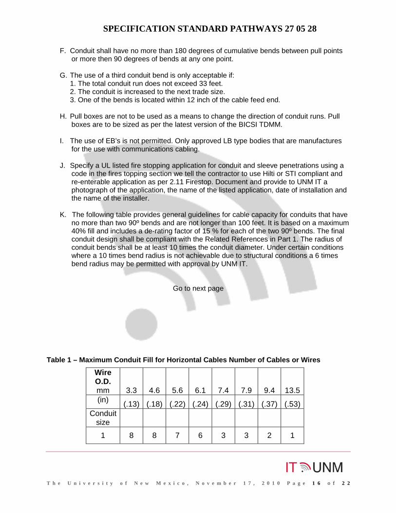
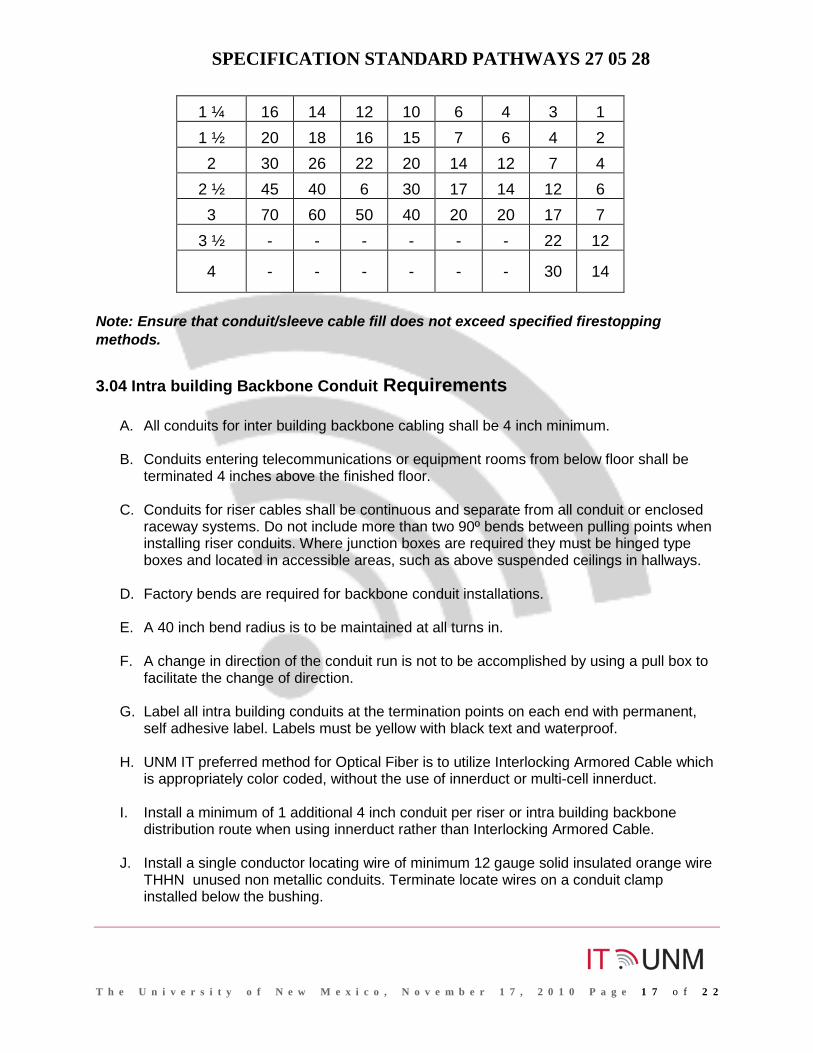
K. The following table provides general guidelines for cable capacity for conduits that have
no more than two 90º bends and are not longer than 100 feet. It is based on a maximum 40% fill and includes a de-rating factor of 15 % for each of the two 90º bends. The final conduit design shall be compliant with the Related References in Part 1. The radius of conduit bends shall be at least 10 times the conduit diameter. Under certain conditions where a 10 times bend radius is not achievable due to structural conditions a 6 times bend radius may be permitted with approval by UNM IT.
Go to next page Table 1 – Maximum Conduit Fill for Horizontal Cables Number of Cables or Wires
Wire O.D. mm 3.3 4.6 5.6 6.1 7.4 7.9 9.4 13.5 (in) (.13) (.18) (.22) (.24) (.29) (.31) (.37) (.53)
Conduit size
1 8 8 7 6 3 3 2 1
SPECIFICATION STANDARD PATHWAYS 27 05 28
T h e U n i v e r s i t y o f N e w M e x i c o , N o v e m b e r 1 7 , 2 0 1 0 P a g e 1 7 o f 2 2
1 ¼ 16 14 12 10 6 4 3 1 1 ½ 20 18 16 15 7 6 4 2 2 30 26 22 20 14 12 7 4
2 ½ 45 40 6 30 17 14 12 6 3 70 60 50 40 20 20 17 7
3 ½ - - - - - - 22 12
4 - - - - - - 30 14
Note: Ensure that conduit/sleeve cable fill does not exceed specified firestopping methods.
3.04 Intra building Backbone Conduit Requirements
A. All conduits for inter building backbone cabling shall be 4 inch minimum.
B. Conduits entering telecommunications or equipment rooms from below floor shall be terminated 4 inches above the finished floor.
C. Conduits for riser cables shall be continuous and separate from all conduit or enclosed raceway systems. Do not include more than two 90º bends between pulling points when installing riser conduits. Where junction boxes are required they must be hinged type boxes and located in accessible areas, such as above suspended ceilings in hallways.
D. Factory bends are required for backbone conduit installations.
E. A 40 inch bend radius is to be maintained at all turns in.
F. A change in direction of the conduit run is not to be accomplished by using a pull box to facilitate the change of direction.
G. Label all intra building conduits at the termination points on each end with permanent, self adhesive label. Labels must be yellow with black text and waterproof.
H. UNM IT preferred method for Optical Fiber is to utilize Interlocking Armored Cable which is appropriately color coded, without the use of innerduct or multi-cell innerduct.
I. Install a minimum of 1 additional 4 inch conduit per riser or intra building backbone distribution route when using innerduct rather than Interlocking Armored Cable.
J. Install a single conductor locating wire of minimum 12 gauge solid insulated orange wire THHN unused non metallic conduits. Terminate locate wires on a conduit clamp installed below the bushing.
SPECIFICATION STANDARD PATHWAYS 27 05 28
T h e U n i v e r s i t y o f N e w M e x i c o , N o v e m b e r 1 7 , 2 0 1 0 P a g e 1 8 o f 2 2
K. Inter duct conduits, where specified by UNM IT, shall have (3) 1.25 inch diameter inner ducts installed in each 4inch conduit assigned for the installation of optical fiber cable.
L. The use on multi-cell innerduct is not permitted unless approved by UNM IT.
M. Where specified by UNM IT install one 1-1/4 inch plenum rated inner ducts for each optical fiber cable specified in all cable tray installations.
N. Label optical fiber inner ducts at each end within six feet of the rack and within one foot of entering or exiting a conduit, label shall be preprinted caution labels that indicate optical fibers cables and describe the size and the termination points of the installed cable. Labels must be yellow with black text and waterproof.
O. Install a single conductor locating wire of minimum 12 gauge solid insulated orange wire THHN for all non metallic optical fiber cables installed in non metallic - conduits, cable trays or other raceways. Do not install locate wire within inner ducts, but rather install them outside the inner ducts and within the conduit. Terminate the locating wire on a conduit clamp or similar device at the conduit termination point below the bushing.
P. All multi-cell conduit and innerducts and multi-cell innerduct shall be rated per NFPA 70 requirements.
Q. Conduits entering entrance, equipment or telecommunications rooms from below grade shall extend 4 inches above finished floor. Location of entrance conduits shall be within 12 inches of room corners.
R. Terminate conduits entering entrance, equipment or telecommunications rooms from above ceiling 4 inches below the finished ceiling or 12 inches above cable tray.
S. Entrance conduits shall be continuous into the building and to the entrance, equipment or telecommunications rooms. Securely fasten all entrance conduits to the building to withstand any cable placing operation.
T. If the entrance conduits exceeds the 180º of total bends limitation, an appropriate sized
junction box, manhole, or handhole is required.
U. All conduits shall have a measured 1320 pull strength mule tape installed and tied off at each end.
3.05 SURFACE MOUNTED RACEWAYS
A. Install sufficient conduit capacity from the cable tray to Surface Mounted Raceways (SMR) to provision the cabling capacity of all outlets in the raceway system.
B. Fit out each outlet in the SMR with all manufacturer specified parts, accessories and
methods necessary for a complete pathway system.

SPECIFICATION STANDARD PATHWAYS 27 05 28
T h e U n i v e r s i t y o f N e w M e x i c o , N o v e m b e r 1 7 , 2 0 1 0 P a g e 1 9 o f 2 2
C. Furnish and install raceway and boxes for renovations and daily work orders when
specified.
D. Ensure there is enough conduit cabling capacity to install all outlets in the system.
E. Do not overfill the capacity of the SMR and ensure space for cable termination and outlets.
F. The minimum cabling capacity of the SMR shall be one inch.
G. Secure raceway system using screws and attachments. Install a minimum of three support screws per raceway section. Do not use adhesive strips as a final means of support.
3.06 CORRIDOR CABLE TRAY SYSTEM
A. Install a complete wall mounted or suspended aluminum or stainless cable tray system
and necessary accessories shall be provided as shown on plans. Install entire cable tray system in accordance with manufacturer’s minimum installation practices and all local governing codes.
B. Coordinate installation of cable tray with other trades to allow a minimum of 12 inches
above, 12 inches in front or at the side rail on one side, and 3 inches below of clearance from piping, conduits, ductwork, etc.
C. Provide submittal drawings, in the form of 8 ½ inch X 11 inch catalog cut sheets, for
the following items: cable tray, fittings, accessories and load data.
D. Cable tray shall not be loaded beyond 40% of manufacturer’s recommended load capacity.
E. Where a new cable tray distribution system encounters an inaccessible area, install sufficient 4 inch EMT sleeves through the area so cabling does not exceed 40% fill ratio.
F. Where cable tray is exposed below ceiling and accessible to the public, install the
appropriate solid bottom and cover inserts to conceal cables or use a 4” conduit system that meets the fill requirements of the corridor cable tray system.
G. Install the cable tray with manufacturer and system compliant waterfalls, turns, T’s
and/or cable exits where cables exit the distribution system.
H. Install one 1-1/4 inch plenum rated inner ducts for each optical fiber cable specified in all cable tray installations, except where Interlocking Armored Optical Fiber is installed.
SPECIFICATION STANDARD PATHWAYS 27 05 28
T h e U n i v e r s i t y o f N e w M e x i c o , N o v e m b e r 1 7 , 2 0 1 0 P a g e 2 0 o f 2 2
I. Label optical fiber inner ducts every start and end points and on each of a wall with preprinted caution labels that indicate the starting and end location optical fibers cables and describe the size and termination points of the installed cable. Labels must be yellow with black text and waterproof.
3.07 INFORMATION TECHNOLOGY ROOM CABLE TRAY SYSTEM
A. Install a complete wall mounted or suspended aluminum or stainless steel cable tray system and the necessary accessories as shown on plans. Install entire cable tray system in accordance with manufacturer’s minimum installation practices and all local governing codes.
B. Install the cable tray with manufacturer and system compliant waterfalls, turns, T’s
and/or cable exits where cables exit the distribution system.
C. TR cable tray shall completely wrap all walls within the room. Cable tray shall extend over all equipment racks.
D. Install cable tray so as not to obstruct lighting, fire suppression or air ducts supply the IT Room.
E. Cable tray shall be a minimum width of 18 inch.
F. Typical cable trays installations will be at nine feet AFF or one foot above equipment racks.
G. Provide submittal drawings, in the form of 8 ½ inch X 11 inch catalog cut sheets, shall be provided for the following items: cable tray, fittings, accessories and load data.
H. Cable tray shall not be loaded beyond 60% of manufacturer’s recommended load capacity.
I. Bond and ground cable tray system to equipment racks using manufacturer approved methods and products. Bond cable tray system to each equipment rack independently.
J. See section 2.08 Cable Trays-Ladder Type
3.08 JUNCTION BOX REQUIRMENTS FOR STATION CONDUITS
A. If the station conduit route exceeds the 180 º of total bends limitation, an appropriate sized junction box is required within a straight section of the conduit run.
B. A junction box shall not be used in place of a bend. All junction boxes in station conduit paths shall be installed within a straight section of the conduit run.
SPECIFICATION STANDARD PATHWAYS 27 05 28
T h e U n i v e r s i t y o f N e w M e x i c o , N o v e m b e r 1 7 , 2 0 1 0 P a g e 2 1 o f 2 2
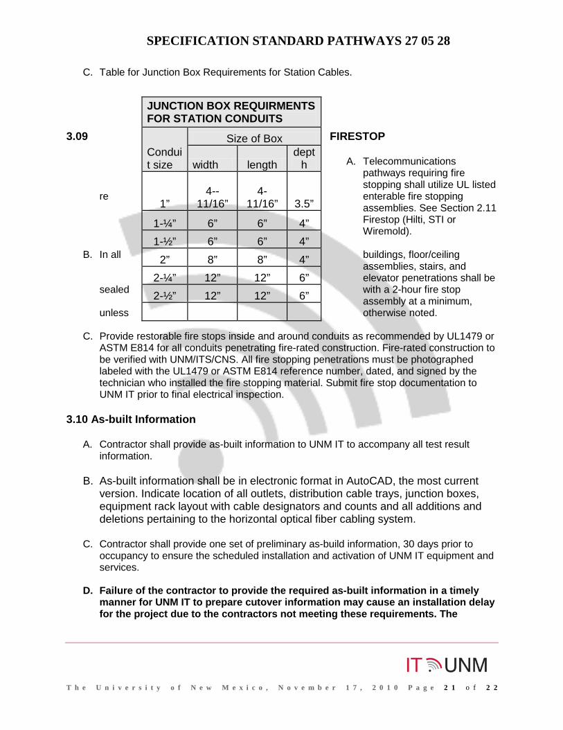
C. Table for Junction Box Requirements for Station Cables.
3.09 FIRESTOP
A. Telecommunications
pathways requiring fire stopping shall utilize UL listed
re enterable fire stopping assemblies. See Section 2.11 Firestop (Hilti, STI or Wiremold).
B. In all buildings, floor/ceiling
assemblies, stairs, and elevator penetrations shall be
sealed with a 2-hour fire stop assembly at a minimum,
unless otherwise noted.
C. Provide restorable fire stops inside and around conduits as recommended by UL1479 or ASTM E814 for all conduits penetrating fire-rated construction. Fire-rated construction to be verified with UNM/ITS/CNS. All fire stopping penetrations must be photographed labeled with the UL1479 or ASTM E814 reference number, dated, and signed by the technician who installed the fire stopping material. Submit fire stop documentation to UNM IT prior to final electrical inspection.
3.10 As-built Information
A. Contractor shall provide as-built information to UNM IT to accompany all test result information.
B. As-built information shall be in electronic format in AutoCAD, the most current version. Indicate location of all outlets, distribution cable trays, junction boxes, equipment rack layout with cable designators and counts and all additions and deletions pertaining to the horizontal optical fiber cabling system.
C. Contractor shall provide one set of preliminary as-build information, 30 days prior to
occupancy to ensure the scheduled installation and activation of UNM IT equipment and services.
D. Failure of the contractor to provide the required as-built information in a timely manner for UNM IT to prepare cutover information may cause an installation delay for the project due to the contractors not meeting these requirements. The
JUNCTION BOX REQUIRMENTS FOR STATION CONDUITS
Conduit size
Size of Box
width length dept
h
1”
4--
11/16” 4-
11/16” 3.5”
1-¼” 6” 6” 4” 1-½” 6” 6” 4”
2” 8” 8” 4” 2-¼” 12” 12” 6” 2-½” 12” 12” 6”

SPECIFICATION STANDARD PATHWAYS 27 05 28
T h e U n i v e r s i t y o f N e w M e x i c o , N o v e m b e r 1 7 , 2 0 1 0 P a g e 2 2 o f 2 2
delivery of the as-built documentation needs to be coordinated with UNM IT as a project milestone.
E. Partial as-builds shall be submitted as additional cabling is completed to meet installation schedules.
F. The Contractor shall provide at substantial completion a list of all uncompleted work and a punch list of open items to the IT Facilities Manager at substantial completion and prior to UNM scheduled activations.
G. If construction drawings are not utilized, contractor shall provide all telecommunications location information on an accurate and electronic formatted scaled floor plan preapproved by UNM IT.
H. Partial as-builds shall be submitted as additional cabling is completed to meet installation schedules. The Contractor shall provide one set of preliminary as-build information including equipment layouts.
I. The final as-built shall be submitted with all corrections made no later than 30 days after
cabling installation is completed.
END OF SECTION