specification of vertical semantic consistency rules of uml class
TRANSCRIPT
SPECIFICATION OF VERTICAL SEMANTIC CONSISTENCY RULES OF UML
CLASS DIAGRAM REFINEMENT USING LOGICAL APPROACH
NURAINI ABDULGANIYYI
A dissertation submitted in partial
fulfillment of the requirement for the award of the
Degree of Master of Computer Science (Software Engineering)
Faculty of Computer Science and Information Technology
Universiti Tun Hussein Onn Malaysia
DECEMBER 2014

v
ABSTRACT
Unified Modelling Language (UML) is the most popular modelling language use for
software design in software development industries with a class diagram being the
most frequently use diagram. Despite the popularity of UML, it is being affected by
inconsistency problems of its diagrams at the same or different abstraction levels.
Inconsistency in UML is mostly caused by existence of various views on the same
system and sometimes leads to potentially conflicting system specifications. In
general, syntactic consistency can be automatically checked and therefore is
supported by current UML Computer-aided Software Engineering (CASE) tools.
Semantic consistency problems, unlike syntactic consistency problems, there exists
no specific method for specifying semantic consistency rules and constraints.
Therefore, this research has specified twenty-four abstraction rules of class‟s relation
semantic among any three related classes of a refined class diagram to semantically
equivalent relations of two of the classes using a logical approach. This research has
also formalized three vertical semantic consistency rules of a class diagram
refinement identified by previous researchers using a logical approach and a set of
formalized abstraction rules. The results were successfully evaluated using hotel
management system and passenger list system case studies and were found to be
reliable and efficient.
vi
ABSTRAK
Unified Modelling Language (UML) merupakan bahasa permodelan yang paling
popular digunakan dalam industri pembangunan perisian. Rajah kelas dalam UML
merupakan rajah yang paling kerap diaplikasikan dalam merekabentuk perisian. Di
sebalik populariti UML, bahasa permodelan ini masih terkesan dengan masalah rajah
tidak konsisten pada tahap peniskalaan yang sama atau berbeza. Masalah ini
disebabkan oleh penghasilan rajah daripada pelbagai sudut pandangan yang berbeza
untuk sesebuah sistem. Masalah ini menghasilkan spesifikasi sistem yang
bercanggah. Secara umumnya, konsistensi sintaktik boleh diperiksa secara automatik
dengan menggunakan alat kejuruteraan perisian berbantukan komputer yang terkini.
Namun begitu, masih belum ada kaedah tertentu untuk menyatakan peraturan dan
kekangan dari segi konsistensi semantik. Oleh yang demikian, kajian ini telah
menyatakan dua puluh empat peraturan peniskalaan bagi menyatakan hubungan
semantik antara tiga kelas dalam rajah kelas kepada hubungan semantik yang setara
antara dua kelas tersebut menggunakan pendekatan logikal. Kajian ini juga telah
menghasilkan spesifikasi formal untuk tiga peraturan konsistensi vertikal yang telah
dinyatakan oleh penyelidik sebelum ini menggunakan pendekatan logikal dan
peraturan peniskalaan formal. Spesifikasi formal yang dihasilkan telah disahkan
dengan menggunakan dua kes ujian iaitu sistem pengurusan hotel dan sistem senarai
penumpang. Hasil ujian telah menunjukkan spesifikasi formal yang dihasilkan adalah
efisien dan boleh dipercayai.

vii
CONTENTS
ACKNOWLEDGEMENT iv
ABSTRACT v
ABSTRAK vi
CONTENTS vii
LIST OF TABLES x
LIST OF FIGURES xi
LIST OF SYMBOLS AND ABBREVIATIONS xii
CHAPTER 1 INTRODUCTION 1
1.1 Problem Statement 4
1.2 Aim and Objectives of the Research 4
1.3 Significance of the Study 5
1.4 Scope of the Study 5
1.5 Report Organization 6
CHAPTER 2 LITERATURE REVIEW 7
2.1 Object Oriented Systems Development Life
Cycle 7
2.1.1 Object Oriented Analysis 8
2.1.2 Object-Oriented Design 9
2.2 Unified Modelling Language 9
2.2.1 UML Model Consistency 10
2.2.2 Class Diagram 12
2.3 Refinement 15
2.4 Formalization 16
2.5 Review of Previous Works 17
2.4 Chapter Summary 20
CHAPTER 3 RESEARCH METHODOLOGY 21

viii
3.1 Vertical Semantic Consistency Rules of Class
Diagram Refinement 21
3.2 Logic and Set 27
3.2.1 Logics and Set Symbols 28
3.3 Research Framework 30
3.3.1 Step 1: Formalization of Class Diagram 30
3.3.2 Step 2: Formalization of Abstraction
Rules of Class‟s Relations and
Cardinality Semantic 30
3.3.3 Step 3: Formalization of Three Vertical
Semantic Consistency Rules of Class
Diagram Refinement 30
3.3.4 Step 4: Evaluation of Class Diagram
Refinement Rules with Two Case
Studies 31
3.4 Chapter Summary 33
CHAPTER 4 FORMALIZATION OF CONSISTENCY RULES 34
4.1 Formalization of Class Diagram 34
4.2 Formalization of Abstraction Rules of Class‟s
Relations Semantics 35
4.2.1 Abstracting Cardinality of class‟s
Relations 38
4.3 Formalization of Vertical Semantic
Consistency Rules of Class diagram
Refinement 39
4.3.1 Formulation of CDRR1 40
4.3.2 Formulation of CDRR2 41
4.3.3 Formulation of CDRR3 43
4.4 Chapter Summary 45
CHAPTER 5 EVALUATION WITH CASE STUDIES 46
5.1 Consistency Checking 46
5.1.1 Evaluation with a Case Study of Hotel
Management System 46
ix
5.1.2 Evaluation with a Case Study of
Passenger List System 53
5.2 Chapter Summary 57
CHAPTER 6 CONCLUSION AND FUTURE WORK 58
6.1 Objectives Achievement 58
6.2 Conclusion 59
6.3 Future Works 59
6.4 Summary 60
REFERENCES 61
VITA 65

x
LIST OF TABLES
2.1 Summary of Literature Review 19
3.1 Logical Terms and Set Symbols Definitions 28

xi
LIST OF FIGURES
1.1 Phases in SDLC 2
2.1 Example of a class 13
2.2 Elements of Class Diagram 14
2.3 Class diagram 15
3.1 Wrong class Diagram refinement violating CDRR1 23
3.2 Successive Class Diagram Refinement in line with CDRR1 23
3.3 Wrong Class Diagram Refinement Violating CDRR2 as class D
not included in the low-level class diagram 25
3.4 A well-refined class diagram in accordance with CDRR1 and
CDRR2 25
3.5 A Well-refine Class Diagram in accordance with CDRR3 26
3.6 Wrong class Diagram Refinement Violating CDRR3 27
3.5 Framework for Formalization of class diagram Refinement
Consistency Rules 32
4.1 Sample of Low-level Class Diagram Dissatisfying CDRR1 40
4.2 Sample of Low-level Class Diagram Dissatisfying CDRR2 42
4.3 Sample of Low-level Class Diagram Dissatisfying CDRR3 44
5.1 High-Level Class Diagram of Hotel Management System 47
5.2 Low-Level Class Diagram of Hotel Management System 47
5.3 High-level class diagram of passenger‟s list system 53
5.4 Low-level class diagram of passenger‟s list system 54

xii
LIST OF SYMBOLS AND ABBREVIATIONS
SDLC - Software Development Life Cycle
UML - Unified Modelling Language
IT - Information Technology
OMG - Object Management Group
CASE - Computer Aided Software Engineering
OOSDLC - Object Oriented Systems Development Life Cycle
SRD - Software Requirement Document
SRS - Software Requirement Specification
OOD - Object-Oriented Design
IS - Information System
OOA - Object-Oriented Analysis
IAC - Integrated Abstraction and Comparison
SAC - Separated Abstraction and Comparison
DL - Description Logic
UCD - Use Case Diagram
AD - Activity Diagram
SD - Sequence Diagram
CD - Class Diagram
LCD - Low-Level Class Diagram
HCD - High-Level Class Diagram
HCLD - Set of Paired classes of High-Level Class Diagram
LCLD - Set of Paired classes of Low-Level Class Diagram
LCL - Low-level Class
HCL - High-Level Class
CLs - Classes
R - Relations

xiii
D - Dependency
G - Generalization
A - Bidirectional Aggregation
A
- Unidirectional Aggregation
S - Association
CL - Class
Attr - Attribute
Opr - Operation
CRule - Cardinality abstraction Rule
CDRR - Vertical Semantic Consistency Rule of Class Diagram
Refinement

1 CHAPTER 1
INTRODUCTION
The increasing dependency on computers and software applications for saving lives,
properties and time, in our contemporary world has escalated to all sectors of human
endeavours. Thereby, led to an increase in the demand of efficiency and reliability of
the computers and the software applications before usage, to avoid claims of what
they were provided to save (that is: lives, properties and time). To ensure efficiency
and reliability of software applications, software experts have agreed to define the
best practice for software development, namely software engineering. The discipline
of software engineering is coined to deal with poor quality of software, get projects
exceeding time and budget under control. It also ensures that software is built
systematically, rigorously, measurably, and within specification. In other words,
software engineering is the study and application of engineering to the design,
development, and maintenance of software from the start to the end of the
development (Laplante, 2007).
In the design phase of software engineering process, Unified Modelling
Language (UML) is one of the modelling languages use for designing software
project. In addition, UML has become an industrially accepted standard for object-
oriented modelling of large, complex systems as well as a basis for software
development methodologies (Lucas et al., 2009). This research is aimed at
addressing the inconsistencies of software at the design stage. Design plays a central
role in the activities that leads to the development or maintenance of good software
by giving an abstract representation of the system prior to development or
maintenance. The consistency of the developed or maintained system with the user
2
requirement specifications depends mostly on the consistency of the design.
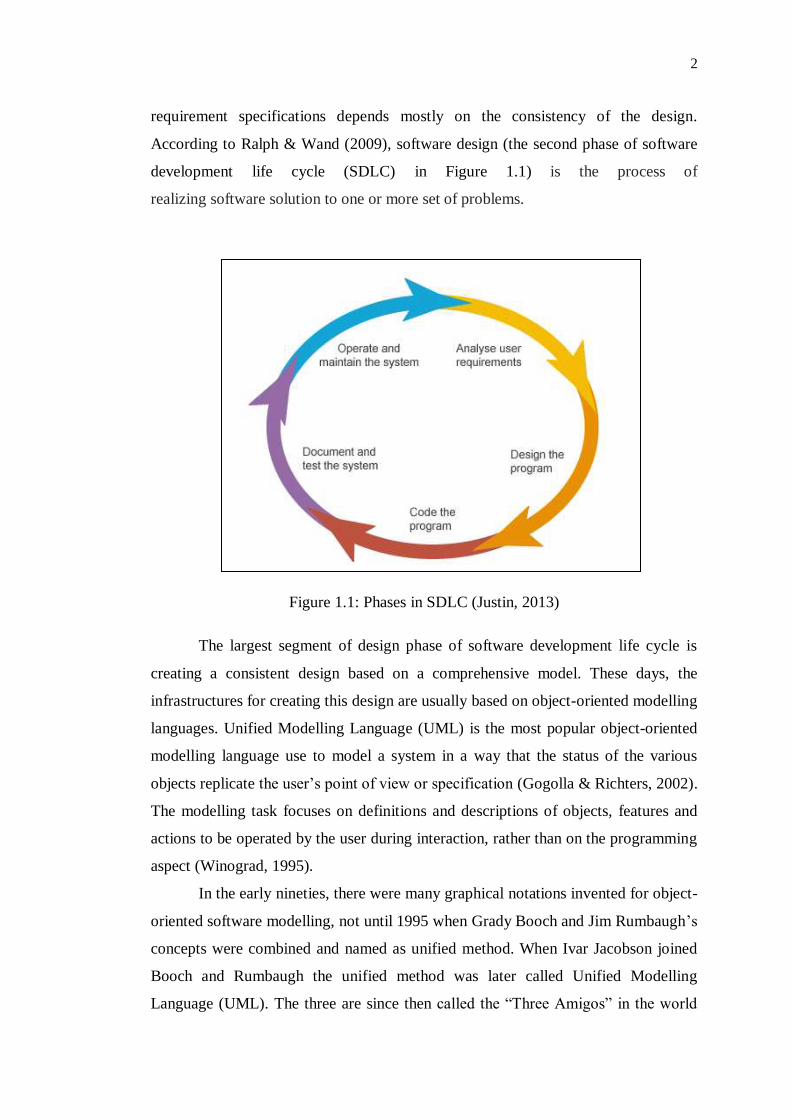
According to Ralph & Wand (2009), software design (the second phase of software
development life cycle (SDLC) in Figure 1.1) is the process of
realizing software solution to one or more set of problems.
Figure 1.1: Phases in SDLC (Justin, 2013)
The largest segment of design phase of software development life cycle is
creating a consistent design based on a comprehensive model. These days, the
infrastructures for creating this design are usually based on object-oriented modelling
languages. Unified Modelling Language (UML) is the most popular object-oriented
modelling language use to model a system in a way that the status of the various
objects replicate the user‟s point of view or specification (Gogolla & Richters, 2002).
The modelling task focuses on definitions and descriptions of objects, features and
actions to be operated by the user during interaction, rather than on the programming
aspect (Winograd, 1995).
In the early nineties, there were many graphical notations invented for object-
oriented software modelling, not until 1995 when Grady Booch and Jim Rumbaugh‟s
concepts were combined and named as unified method. When Ivar Jacobson joined
Booch and Rumbaugh the unified method was later called Unified Modelling
Language (UML). The three are since then called the “Three Amigos” in the world

3
of software engineering and information technology (IT) (Weilkiens & Oestereich,
2010). There are seventeen types of diagrams in UML 2.5 (Ciancarini, 2013 &
Ambler, 2013).
As UML is used to model system from different viewpoints and abstraction
levels, consistency issues need to be taken into consideration as diagrams
representing various aspects of the system are produced. Inconsistency occurs when
the diagrams are not properly related to each other in order to form a reliable
description of the user requirement specifications (Lucas et al., 2009). The benefit of
checking consistency of a UML model at design stage shall never be over
emphasized as quality assurance technique. It often results in better design; earlier
detection of errors, flaws, product delivery within budget and time scheduled.
Moreover, consistent model makes system maintenance, and team works easier even
at different geographic location (Nugroho & Chaudron 2009, Usman et al., 2008).
There are two types of inconsistency problems: vertical and horizontal
consistency problems. Those related to models constructed at the same level of
modelling abstraction are called intra-consistency or horizontal consistency
problems. While those between models built at different levels of abstraction i.e.
between a model and its successive refinement are called inter-consistency or vertical
consistency problems (Huzar et al., 2005). Inconsistency problems occur in a UML
model due to multi-view nature of the UML diagrams and iterative process of
information system development. Other possible sources of inconsistency in UML
include; imprecise semantic nature of the UML diagrams and distributed
development of a system with several developers. The developers may on occasions,
be geographically distributed locally or globally, with various interpretations of both
the requirements and the UML notations (Huzar et al., 2005).
Furthermore, Lucas et al., (2009) classified previous works on consistency
management into syntactic and semantic consistency problems. They also suggested
the use of formal approach to solve inconsistency problems in a way that will
improve feedback of the consistency check with aim of easing modellers‟ task of
identifying and handling problem(s) detected in a model. Therefore, this dissertation
aims at formalizing class diagram elements and vertical semantic consistency rules of
class diagram refinement using a logical approach. This technique will benefit from
the properties of mathematical logic such as transitivity, associativity and
4
commutativity, thereby, making it precise, concise and more efficient than the
previous techniques in terms of accuracy, space and time complexity.
1.1 Problem Statement
Despite the popularity of UML for object-oriented software modeling in software
development industries, UML diagrams are being affected by inconsistency
problems at the same and different modeling abstractions. Inconsistency problems of
UML diagrams are the major setback recorded affecting modeling with UML.
Solving UML inconsistencies have gained the attention of many researchers on how
to handle inconsistency in UML, though there are limited works in UML vertical
semantic inconsistency management (Lucas et al. 2009, Torre & Genero 2014). In
general, syntactic consistency problems can be automatically checked and, therefore,
are supported by current UML CASE tools (Khalil & Dingel 2013). Unlike syntactic
consistency, there is no specific method for specifying semantic consistency rules
and constraints (Khalil et al. 2013). Shen, Wang, & Egyed (2009) identified three
vertical semantic consistency rules of a class diagram refinement and used informal
approaches to manage them. The approaches used were Integrated Abstraction and
Comparison (IAC), and Separated Abstraction and Comparison (SAC). These
techniques require a significant amount of time and memory space in order to handle
inconsistencies of a class diagram refinement. These are due to the large number of
rules check and iterations involved in the algorithms. On the contrary, this research
will formulate the same vertical semantic consistency rules of class diagram
refinement achieved with SAC and IAC in a more effective and efficient manner
using a logical approach.
1.2 Aim and Objectives of the Research
This research aims to formalize class diagram elements and vertical semantic
consistency rules of class diagram refinement using logical approach.

5
The objectives of the research are to:
(i) identify UML class diagram elements for vertical semantic consistency of class
diagram refinement.
(ii) produce a formal specification for the three rules identified by Shen et al.,
(2009).
(iii) validate (ii) using hotel management system and passenger list system case
studies.
1.3 Significance of the Study
Modelling a software system with UML helps to improve productivity and quality of
the software product by ensuring that all stakeholders understand the target system in
a single way. Consequently reduces the defect density in the code and the time
required to fix the defects (Nugroho & Chaudron 2013). However, these advantages
are often challenged by inconsistency of the UML diagrams. Therefore, there is a
need to check consistency of the UML models at design stage to obtain better design,
detect errors and flaws at the early stage of development. Moreover, consistent
design facilitates product delivery within budget, time scheduled, and make
teamwork comfortable even at different geographic locations (Nugroho & Chaudron
2009, Usman et al., 2008). Hence, formalizing class diagram elements and vertical
semantic consistency rules of class diagram refinement will reduce the ambiguity of
UML CASE tool support for vertical semantic inconsistency management of class
diagram refinement (Shen et al., 2009).
1.4 Scope of the Study
This study will be restricted to formalization of class diagram elements and three
vertical semantic consistency rules of class diagram refinement identified by Shen et
al., (2009) using a logical approach. The results will be validated using hotel
management system and passenger list system case studies.

6
1.5 Report Organization
This dissertation is organized as follows: Chapter 2 is the literature review of the
research. It presents a general discussion of the major aspects of the study. It begins
by explaining object-oriented software development life cycle, object-oriented
analysis, and object-oriented design. It further discusses UML for object-oriented
software design and inconsistencies in UML. The chapter then discusses the related
works to the study. Chapter 3 discusses the methodology of the research. It presents
an explanation of three vertical semantic consistency rules of class diagram
refinement, definition of logic and set, logic and set symbol and finally gives
explanation and sketch of the research framework. Chapter 4 will formalize the
vertical semantic consistency rules of class diagram refinement. It presents a
formalization of class diagram elements, class diagram abstraction rules and finally
presents formalization of the three vertical semantic consistency rules of class
diagram refinement. Chapter 5 will evaluate the formalized rules with a case study. It
presents a case study of hotel management system to evaluate the formalized rules.
Finally, Chapter 6 presents conclusion of the research and outlines some future
works.

2 CHAPTER 2
LITERATURE REVIEW
This chapter discusses literature related to this research in order to establish facts
about the problem this study addresses. Section 2.1 and its subsections explain one of
the methodologies of developing quality software in the present state of technology.
Section 2.2 gives a brief history and explanation of Unified Modelling Language
(UML), and Section 2.3 reviews previous works related to this study.
2.1 Object Oriented Systems Development Life Cycle
Object-Oriented Systems Development Life Cycle (OOSDLC) is a process of
developing high-quality software that meets both customer and actual world
requirements. OOSDLC consists of three primary processes: Object-oriented
analysis, Object-oriented design, and Object-oriented implementation. These
processes are seen as a sequence of alteration, where output of one transformation
becomes input for subsequent transformation. Fundamentally, product of object-
oriented analysis is input to object-oriented design; product of object-oriented design
is input to object-oriented implementation of the intended system using object-
oriented programming techniques (Booch, 2007).

8
2.1.1 Object Oriented Analysis
Object-Oriented Analysis (OOA) is a process of analysis that scrutinizes client‟s
requirements from a viewpoint of classes, objects and relationship among them, as
contained in the vocabulary of the problem domain (Booch, 2007). The result of this
analysis includes both functional and non-functional requirements that are document
in a Software Requirement Document (SRD). SRD contains Software Requirement
Specification (SRS) which presents the result of the functional requirement analysis
using Unified Modelling Language (UML) diagrams. SRS is used to set basis for
agreement between a developer and a client on what the software product is to do as
well as what it is not expected to do. Moreover, SRS allows a thorough evaluation of
requirements before design can commence and thus reducing the chances of
redesigning. SRS can also serve as a reasonable basis for estimating a product cost,
risks and schedules (McConnell, 2010).
There are many proven methods for analysis of an object-oriented system to
get various classes and objects from elements of the problem domain. These methods
include classical, behaviour, domain, use case, CRC cards, informal English
description, and structured analysis method (Booch, 2007). For instance, to analyze a
system using the classical analysis method, Shlaer & Mellor (1988) proposed that
candidate classes and objects, should regularly come from one of the following
sources. First, tangible objects such as bicycle, washing machine, telemetry data,
pressure sensors among others. Second, role model such as farmer, engineer, and
doctor. Third, events like landing, packaging, malting, interrupting and requesting.
Fourth, interactions like loan, withdrawal, meeting, and intersection (Booch, 2007).
Moreover, Coad & Yourdon (1991) proposed other sources of potential
objects as follows. First, structures like "Is a" and "part of" relationships. Second,
other external systems with which an application interacts. Third, devices an
application interacts with. Fourth, events that must be recorded. Fifth, roles play by
users in interacting with an application. Sixth, any physical location which is critical
to an application such as classroom, university and hospital. Lastly, organizational
units to which an application users belong. The results obtained from any of the
chosen analysis approaches are modelled using UML and documented in the SRS,
which serves as input to the object-oriented design phase (Booch, 2007).

9
Consequently, this research will present formalization of vertical semantic
consistency rules of class diagram refinement. The formalized rules will be used to
check consistency of a class diagram at object-oriented design phase with a class
diagram obtained at object-oriented analysis phase of software development.
2.1.2 Object-Oriented Design
Object-oriented design (OOD) is a technique of design that deals with object-
oriented breakdown and a notation for representing both logical and physical as well
as static and dynamic aspect of the system under design (Booch, 2007). OOD uses
class and object concepts to structure a system logically while structural design uses
algorithmic concepts. The objective of OOD is to design classes (identified during
the analysis phase), graphical user interface classes and add other classes that will
breakdown or refine the classes obtained in the analysis phase. Furthermore, during
this phase, other objects and classes that will support implementation of the user‟s
requirements, may also be identified and defined, such as classes for connection to
the database (Booch, 2007). Consequently, produces a technical description of how
solution to client‟s requirements and expectations can be achieved using the various
diagrams of UML. The following section gives details information on UML,
definition, and notations of a class diagram.
2.2 Unified Modelling Language
The Unified Modelling Language (UML) is a language and notation system use to
specify, construct, visualize, and document models of software systems (OMG,
2005). It provides sets of diagrams to model structural, behavioural, and interaction
aspects of an object-oriented system. Each diagram depicts a particular design aspect
of the system. UML consists of many diagrams depending on the version. For
example, UML version 2.0 has 13 diagrams (OMG, 2005), both UML version 2.2
and 2.4 have 14 diagrams (Zhao, et al., 2011) and UML version 2.5 has 17 diagrams
(Ambler, 2013). These 17 diagrams are divided into three categories. The first
category contains ten diagrams use to represent static structures of an application and

10
are called structure diagrams. These include class, object, component, composite
structure, package, deployment, profile, model, manifestation, and network
architecture diagram. The second category comprises of three diagrams use to
represent general types of behaviours in a software application and are referred to as
behaviour diagrams. Behaviour diagrams include use case, activity and state machine
diagram. The last category contains four diagrams representing different aspects of
interactions of the system underdevelopment and is called interaction diagrams. The
diagrams in this category are all derived from the more general behaviour diagrams.
Interaction diagrams include sequence, communication, timing, and interaction
overview diagram. The presence of many UML diagrams, to model a system, brings
a variety of views that overlap with respect to information depicted in each that can
leave overall system design specification in an inconsistent state.
2.2.1 UML Model Consistency
Consistency in UML model is a state in which the structures, features and elements
that appear in a model are compatible and in alignment with contents of the model
and other related models with respect to requirement being modeled and UML meta-
model (Spanoudakis & Zisman, 2001). For example, the structures, functions and
relations in an initial class diagram obtained during an analysis phase of a software
development must be compatible with a detailed class diagram developed during the
design phase of the software development.
In addition, unambiguous and consistent UML models are necessary for
successful development of quality Information System (IS) (Bansiya & Davis, 2002).
However, UML model is hardly free of inconsistency problems within or with other
models at the same or different abstraction levels. Inconsistency in UML model(s)
usually arose due to analysts or designers viewing the same system from different
points of views. Other possible causes of UML inconsistency are iterative process of
an IS development, lack of UML knowledge or practice, imprecise semantic nature
of the UML diagrams, difference in geographical location of developers, and
multiple interpretations of user‟s requirements and UML notations (Huzar et al.,
2005).

11
Iterative process of an IS development involves UML diagrams abstraction.
Abstraction is the process of creating decomposition of a diagram into simpler and
better understood primitive diagrams. This procedure has many underlying
methodologies. An abstraction can also be used to refer to a model (Burback, 1998).
The process of transforming one abstraction into a more comprehensive abstraction
is called refinement. The abstracted diagram is referred to as a refinement of the
original one (Burback, 1998). Abstractions and its refinements naturally do not
coexist in the same system description. Accurately, what is meant by a more
comprehensive abstraction is not well defined. Therefore, there is a need to support
substitutability of concepts from one abstraction to another (Burback, 1998).
Furthermore, consistency checking must be performed within and between
different UML models to reduce the cost, time, and effort of maintenance (Dam &
Winikoff, 2010). This is principally true in the context of design evolution. There are
two types of consistency problems in UML; vertical and horizontal. Vertical and
horizontal consistency problems are also classified into syntactic and semantic
consistency problems. The definitions of the types and classifications of
consistencies are described as follows.
(i) Vertical Consistency
Vertical consistency in UML is a state of semantic or syntactic compatibility of
models built at different levels of abstraction such as between a model and its
refinement. It is also called inter-consistency (Huzar et al., 2005). For example, an
abstract class diagram developed in the analysis phase of software development must
be semantically and syntactically consistent with a detailed class diagram developed
in the design phase of the software development.
(ii) Horizontal Consistency
Horizontal consistency is a state of semantic or syntactic compatibility of models
built at the same level of modelling abstractions. It is also called intra-consistency
(Huzar et al., 2005). For example, a class diagram describing the static aspects of an
abstract model must be semantically and syntactically consistent with a state machine
diagram describing the dynamic aspects of the classes in the model.

12
(iii) Semantic Consistency
Semantic consistency is a state that requires models‟ behaviours to be semantically
compatible with one another (Engels, et al., 2001). For example, a class diagram and
its refinement must be semantically compatible with each other. Unlike syntactic
consistency, there is no specific method for specifying semantic consistency rules
and constraints (Khalil & Dingel, 2013).
(iv) Syntactic Consistency
Syntactic consistency guarantees that a model conforms to abstract syntax of the
modelling language as specified by its meta-model (Engels et al., 2001). For
example, in a class diagram, the design of each class as well as the relationship
between them must be syntactically correct in accordance with the class diagram
meta-model. In general, syntactic consistency can be automatically checked and
therefore is supported by current UML CASE tools (Khalil & Dingel, 2013).
The inconsistency type depends on whether the inconsistency issue is due to
violation of rule(s) of UML meta-model or compatibility of UML diagrams used in
the modelled system (Engels, Küster, et al., 2001, Lucas et al., 2009). Despite all the
challenges of consistency uncertainty of UML models, UML is also the most widely
used modelling language in object-oriented software development industries. Class
diagram is the most used UML diagram (Dobing & Parsons, 2006). For this reason,
this research will propose a formal specification for three vertical semantic
consistency rules of class diagram refinement identified by Shen et al., (2009) using
a logical approach. The following section will dwell on a class diagram and its
properties.
2.2.2 Class Diagram
A class diagram is the most fundamental and broadly used UML diagram. It
illustrates the static view of a system, consisting of classes, their interrelationships,
operations and attributes of the classes (Szlenk, 2006). A Class is the building blocks
of an object-orientated system. It is used to depict the static view of a system or part

13
of the system, describing its attributes and methods (operations) without detailing
how to achieve the methods. A class in UML is represented by a rectangle showing
the name of the class and optionally names of methods and attributes. Partitions are
used to divide the class name, attributes and operations. The top partition of a class
contains the class name, the second partition contains attributes of the class, and the
third partition contains operations in the class and their parameters if any. The
notation that precedes the attribute‟s or method‟s name indicates the visibility of the
element. If “+” (plus) symbol is used, the attribute or method, has a public level of
visibility. If “–”(minus) symbol is used, the attribute or method, is private.
Furthermore, “#” symbol allows a method or attribute, to be defined as protected
while “~” symbol indicates package visibility (Weilkiens & Oestereich, 2010).
Figure 2.1 shows an example of class, named Rectangle.
Figure 2.1: Example of a class (Coates, 2012).
Furthermore, a class diagram illustrates relationships between classes and
interfaces. Generalizations, aggregations, and associations are all precious in
reflecting inheritance, composition or usage, and connections, respectively between
classes (Weilkiens & Oestereich, 2010). A generalization is an abstraction principle
use to organize semantics of a model hierarchically. It shows the relationship
between a general class and a particular class. The particular class posses all the
characteristics of the general class, and other special features and behaves in a way
well-suited to the general class. An association expresses a tuple of typed instances.
It is represented by a straight line, and at least two properties take part in the
association. Multiplicity of an association states how many objects of the associated
14
classes can participate in the association. If this number is a variable, a range is stated
that is, the minimum and maximum value. A minimum of “0” means that the
relationship is optional: the relationship exists, but the number of elements involved
in the association may be 0. Dependency is used to describe dependency between
two elements of a system. An aggregation is an association extended by a
semantically noncommittal comment that participating classes have no equal-ranking
relationship. Instead, they represent a whole-parts hierarchy. An aggregation is used
to illustrate how something whole is logically composed of its parts. A composition
is a strict form of aggregation, where the existence of its parts depends on the whole.
The whole is the owner of its parts. The composition also describes how something
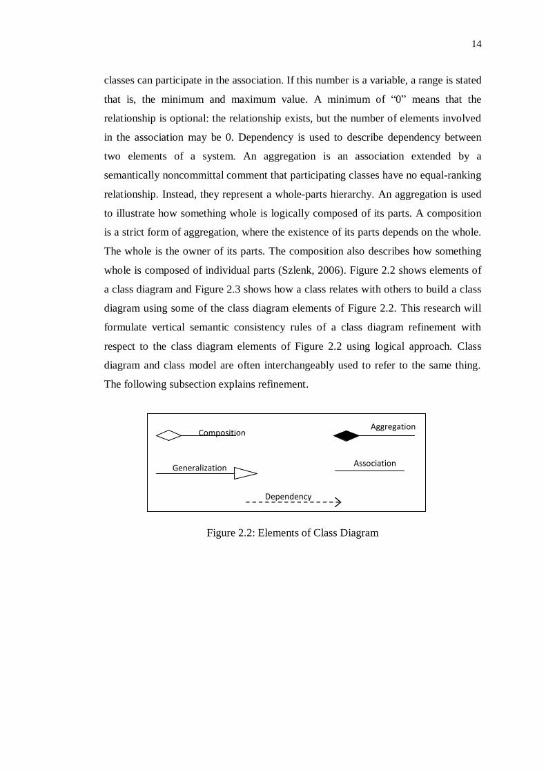
whole is composed of individual parts (Szlenk, 2006). Figure 2.2 shows elements of
a class diagram and Figure 2.3 shows how a class relates with others to build a class
diagram using some of the class diagram elements of Figure 2.2. This research will
formulate vertical semantic consistency rules of a class diagram refinement with
respect to the class diagram elements of Figure 2.2 using logical approach. Class
diagram and class model are often interchangeably used to refer to the same thing.
The following subsection explains refinement.
Figure 2.2: Elements of Class Diagram
Composition
Aggregation
Association Generalization
Dependency

15
Figure 2.3: Class diagram (Coates, 2012)
2.3 Refinement
Refinement is a procedure of transforming a model into a more comprehensive
model. The new model is referred to as a refinement of the original model (Burback,
1998). According to Hnatkowska et al., (2004), refinement is a relationship that
represents a more detailed specification of something that has previously been
specified at a certain level of detail. For example, a design phase class diagram is a
refinement of the analysis phase class diagram. Models and their refinements
naturally do not coexist in the same s ystem description. Precisely, what is meant by
a more comprehensive model is not well defined. Thus, there is a need to get support
for substitutability of concepts from one model to another (Burback, 1998).
Moreover, relationships between elements in different models have no
semantic impact on the contents of the models because of the self-containment of the
models. However, they are useful for tracing refinements and for keeping track of
requirements between models (Hnatkowska et al., 2004).

16
2.4 Formalization
This research will use a logical approach to formalize vertical semantic consistency
rules of class diagram refinement. In mathematics, the study of logic deals with
statements or propositions. A statement is a sentence that is either true or false, but
not both. For example, it rained yesterday. Logical investigation conveys clearly the
required relationships between facts about the real world and show where possibly
unwarranted assumptions enter into them. Mathematically, logic is referred to as a
tool for working with complex compound statements which involves using formal
language for expressing them, concise notation for writing them and a methodology
for objectively reasoning about their truth or falsity. Also, logic is the basis for
stating formal proofs in all branches of mathematics (Shoenfield, 1967).
Set theory is a natural extension of logic and provides further useful notation
as well as some interesting insights of its own. Set is a well-defined collection of
objects. Even though any object can be collected into a set, set theory is applied most
often to objects that are relevant to mathematics. The language of set theory can be
used in the definitions of nearly all mathematical objects (Stoll, 2012). This research
will identify elements of a class diagram and formalized it using set theory. The
formal definition of class diagram will then be used to logically formalize abstraction
rules and cardinality semantics of class‟s relations. Finally, the formalized definition
of class diagram, abstraction rules and cardinality semantics of class‟s relation will
be used to formally specify three vertical semantic consistency rules of class diagram
refinement.
Besides, logical approach has been considered sufficient for checking and
managing inconsistency in UML diagrams. Lucas et al. (2009) found that 75% of the
techniques used in 44 proposals from 2001 to 2007 for detecting and handling
inconsistency problems were formal methods and 21% of the procedures were
logical approach. The authors concluded that this high percentage disclosed, that use
of formal methods, offer advantages in dealing with consistency problems, even
though none of the formal methods used standout above the others. The authors
thereby recommended using a formal technique to handle inconsistency problems of
UML diagrams in future works.
17
2.5 Review of Previous Works
Although there are many proposals for enhancing modelling with UML, only a few
works on UML semantic consistency management (Lucas et al., 2009; Torre &
Genero, 2014). While some of the proposals used formal methods to enhance UML
modelling and software development process, others used informal methods. Lima et
al., (2009) proposed a formal verification and validation (V&V) technique to check
semantic consistency of a sequence diagram. The proposed technique generate
PROMELA-based model from interactions expressed in a given sequence diagram.
SPIN model checker is then used to simulate the execution and to confirm sequence
diagram properties are written in Linear Temporal Logic (LTL). The technique was
implemented as an Eclipse plug-in, with human understandable feedback to the
developer. The following semantic rules of a sequence diagram were addressed;
lifeline that performed the last action, the last completed action (sent or received),
message used in the final action, and lifeline to/from which a message was
sent/received. This technique is difficult to extend to static components of UML
diagrams. According to Holzmann & Gerard (2007), PROMELA is a process
modelling language which intended use is to verify the logic of parallel systems. In
other words, PROMELA can be highly suitable for modelling dynamic properties but
not static features.
Shen, Wang, & Egyed (2009) presented two informal methods for checking
consistency between a class diagram and its refinement at different levels of
modelling abstractions. The presented techniques were Integrated Abstraction and
Comparison (IAC), and Separated Abstraction and Comparison (SAC). The authors
further demonstrated that SAC is highly favourable for consistency checking of
software models than IAC. The techniques addressed three semantic consistency
rules of class diagram refinement. The addressed rules are stated as follows; (1)
every low-level class refines at most one high-level class, (2) every high-level class
has at least one low-level class, which refines the high-level class, and (3) the group
of relationships between any two high-level classes must be identical with the group
of relationships between their corresponding low-level classes. The methods were
implemented and integrated with IBM Rational Rose design tool.
18
He et al. (2013) proposed a method of ontology-based semantics confirmation
of UML behaviour diagrams. The authors divided semantics of behaviour diagrams
into static and dynamic semantics. The static semantics are defined as the notations
and constraints in UML behavioural diagrams while the dynamic semantics are
defined as the semantic relations among the instances of the notations while
interacting. The static semantics of behavioural diagrams are transformed into
ontology web language description logic (OWL DL) by converting UML behaviour
diagrams and their meta-models into a DL knowledge base. While the dynamic
semantics are specified in DL-Safe rules that are then expressed by SWRL (Semantic
Web Rule Language) and added to the OWL DL ontology. The OWL DL is then
used to check both vertical and horizontal semantic consistency of activity, sequence,
and state diagrams.
Knapp, Mossakowski, & Roggenbach (2014) proposed a technique called
institution based heterogeneous approach for checking semantic consistency among
UML diagrams. The proposed framework can be used to verify consistency of
different UML diagrams both horizontally and vertically. The vertical semantic
consistency addressed in the proposal checks whether the state machine satisfies an
OCL invariant or an OCL pre-/post-condition.
However, there are still issues with UML consistency checking and
management, due to ambiguity of some of the proposed rules, unconformity to meta-
model of the UML diagram(s), in-extensibility of some of the techniques, sometimes
meaningless consistency rules proposals as well as impractical applicability of the
proposed rules (Lucas et al., 2009). Table 2.1 summarises the previous works on
semantic consistency in UML diagrams.
19
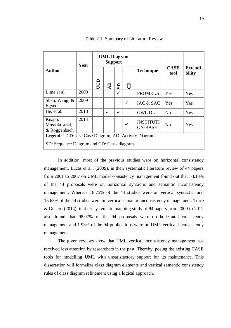
Table 2.1: Summary of Literature Review
Author
Year
UML Diagram
Support
Technique CASE
tool
Extendi
bility
UC
D
AD
SD
CD
Lima et al. 2009 PROMELA Yes Yes
Shen, Wang, &
Egyed
2009 IAC & SAC Yes Yes
He, et al. 2013 OWL DL No Yes
Knapp,
Mossakowski,
& Roggenbach
2014
INSTITUTI
ON-BASE No Yes
Legend: UCD: Use Case Diagram, AD: Activity Diagram
SD: Sequence Diagram and CD: Class diagram
In addition, most of the previous studies were on horizontal consistency
management. Lucas et al., (2009), in their systematic literature review of 44 papers
from 2001 to 2007 on UML model consistency management found out that 53.13%
of the 44 proposals were on horizontal syntactic and semantic inconsistency
management. Whereas 18.75% of the 44 studies were on vertical syntactic, and
15.63% of the 44 studies were on vertical semantic inconsistency management. Torre
& Genero (2014), in their systematic mapping study of 94 papers from 2000 to 2012
also found that 98.07% of the 94 proposals were on horizontal consistency
management and 1.93% of the 94 publications were on UML vertical inconsistency
management.
The given reviews show that UML vertical inconsistency management has
received less attention by researchers in the past. Thereby, posing the existing CASE
tools for modelling UML with unsatisfactory support for its maintenance. This
dissertation will formalize class diagram elements and vertical semantic consistency
rules of class diagram refinement using a logical approach.

20
2.4 Chapter Summary
This chapter has reviewed object-oriented system development life cycle, object-
oriented analysis and object-oriented design and their relationship to this study. This
chapter further discussed Unified Modelling Language (UML), consistency in UML,
types of consistencies, classification of consistencies, class diagram and finally
reviewed previous works related to the study. The next chapter presents a
methodology of this research.

3 CHAPTER 3
RESEARCH METHODOLOGY
This chapter explains the systematic methodology of this research in order to check
inconsistency problems between two-class diagrams at different levels of
abstractions. Further, this study will use elementary set theory and logic to check the
inconsistency problems. Section 3.1 will state the rules to be addressed by the
research. Section 3.2 will define and give examples of set symbols and logical terms
that will be use to formalize a class diagram and check the rules stated in Section 3.1.
Section 3.3 presents a framework of how the formalization will be used to check
inconsistency between class diagrams at different levels of abstractions. The last
Section 3.4 will present summary of the chapter.
3.1 Vertical Semantic Consistency Rules of Class Diagram Refinement
This section discusses three (3) vertical semantic consistency rules of a class
diagram refinement identified by Shen et al., (2009). Refinement occurs when an
initial class diagram obtained during the analysis phase of a software development is
broken-down to a detailed class diagram during design phase of the software
development. This research shall refer to the initial class diagram obtained at analysis
phase as high-level class diagram and detailed class diagram obtained at design
phase as low-level class diagram.

22
According to Shen et al., (2009), two-class diagrams at different levels of
abstractions are said to be consistent with each other if the following consistency
rules (CDRR) are satisfied:
(i) CDRR1: Every class of a low-level class diagram (LCD) refines at most one
class of the high-level class diagram (HCD): ensures that a low-level class refines at
most one high-level class. This means that a low-level class can be a subclass of at
most one high-level class: specialization.
Refinement is a procedure of transforming one class into simpler and more
understood primitive classes (Burback, 1998). Specialization means creating new
subclasses from an existing class. Generalization is a process of extracting shared
characteristics from two or more classes and combining them into a generalized
super class. Shared characteristics can be attributes, associations, or methods.
Figure 3.1 explains CDRR1 using a high-level class diagram and a low-level
class diagram. The high-level class diagram consists of three classes; A, B and C. The
low-level class diagram consists of all classes in the high-level class diagram
probably with additional properties or attributes (i.e. class A´, B´ and C´). The low-
level class diagram also contained class D and E. Applying CDRR1 to Figure 3.1
reveals that: the low-level class diagram is a wrong refinement of the high-class
diagram due to class E refining two classes that are part of the high-level class
diagram, thereby violating CDRR1.
Another example of CDRR1 is shown in Figure 3.2 which consists of a high-
level class diagram and a low-level class diagram. The high-level class diagram
consists of three classes A, B and C. The low-level class diagram consists of all
classes in the high-level class diagram with perhaps additional properties or attributes
(i.e. class A´, B´ and C´) and additional two classes, D and E. The low-level class
diagram is a successive refinement of the high-level class diagram with class D
specializing class A, and class E generalizing classes B and C.

23
Figure 3.1: Wrong class Diagram refinement violating CDRR1
Figure 3.2: Successive Class Diagram Refinement in line with CDRR1
High-Level Class Diagram
Low-Level Class Diagram
A B C
A´ B´
C´
D E
A B C
A´ B´ C´
D E
High-Level Class Diagram
Low-Level Class Diagram

24
(ii) CDRR2: Every high-level class has at least one low-level class, which refines
it: ensures that every high-level class is refined or present in the low-level class
diagram since a class is a refinement of itself. In another world, every high-level
class must be present in the low-level class diagram with either further refinement or
no refinement.
CDRR2 is illustrated in Figure 3.3 and 3.4. The low-level class diagram of
Figure 3.3 consists of class A, B, C and D and the high-level class diagram consists of
class A´, B´, C´, E, F, G, H, I, and J. Class D of the high-level class diagram is
missing in the low-level class diagram and that violate CDRR2 because class D does
not refine itself nor another class in the low-level class diagram. Moreover, class F
and J refined or specialized class A, class E refined or specialized class B, and lastly
class G, H and I refined class C.
Figure 3.4 consists of high-level class diagram and low-level class diagram.
The high-level consists of class A, B, C and D while the low-level class diagram
consists of class A´, B´, C´, D´, E, F, G, H, I, and J. The low-level class diagram is
a successive refinement of the high-level class diagram. Class G, H and I refined or
specialized class D, class E generalized class C, class F and J refined or specialized
class B and finally the class A refined itself.

61
REFERENCES
Alexander, S., Gerhard, F., & Marina, P. (2015). Constructing Class Diagrams.
SourceMaking. Retrieved on January 25, 2015, from http://sourcemaking.com/
uml/modeling-it-systems/structural-view/constructing-class-diagrams.
Ambler, S. W. (2013). UML 2.5: Do You Even Care? Dr Dobb’s. Retrieved on
March 24, 2014, from http://www.drdobbs.com/architecture-and-design/uml-
25-do-you-even-care/240163702.
Bansiya, J., & Davis, C. G. (2002). A Hierarchical Model for Object-Oriented
Design Quality Assessment. IEEE Transactions on Software Engineering,
28(1), pp. 4–17.
Booch, G. (2007). Object-Oriented Analysis and Design with Applications. Quality
Assurance. Addison-Wesley.
Burback, R. (1998). Software Engineering Methodology: The Watersluice. Stanford
University.
Ciancarini, P. (2013). UML Basics. University of Bologna. Retrieved on May 02,
2014, from http://www.cs.unibo.it/cianca/wwwpages/ids/uml.pdf.
Coad, P., & Yourdon, E. (1990). Object-oriented analysis. Englewood Cliffs, New
Jersey: Yourdon Press Prentice Hall.
Coates, C. (2012). UML 2 Class Diagram Tutorial. Sparx Systems. Retrieved on May
02, 2014, from http://www.sparxsystems.com/resources/uml2_tutorial/
uml2_classdiagram.html.
Dam, H. K. D. H. K., & Winikoff, M. (2010). Supporting change propagation in
UML models. Software Maintenance (ICSM), 2010 IEEE International
Conference on.
Dobing, B., & Parsons, J. (2006). How UML is used. Communications of the ACM,
49(5), pp. 109–114.
Engels, G., Küster, J. M., Heckel, R., & Groenewegen, L. (2001). A Methodology
for Specifying and Analyzing Consistency of Object-Oriented Behavioral
Models. ACM SIGSOFT Software Engineering Notes, 26, pp. 186–195.
62
Gogolla, M., & Richters, M. (2002). Expressing UML Class Diagrams Properties
with OCL. In Object Modeling with the OCL (pp. 85–114). Springer-Verlag
Berlin Heidelberg.
He, H., Wang, Z., Dong, Q., Zhang, W., & Zhu, W. (2013). Ontology-Based
Semantic Verification for Uml Behavioral Models. International Journal of
Software Engineering and Knowledge Engineering, 23(02), pp. 117–145.
Hnatkowska, B., Huzar, Z., Kuźniarz, L., & Tuzinkiewicz., L. (2004). On
understanding of refinement relationship. Consistency Problems in UML-based
Software Development: Understanding and Usage of Dependency, 7. (pp. 7–
17).
Holzmann, G. J., & Gerard, J. (1990). Design and Validation of Computer Protocols.
Prentice-Hall, Inc. Upper Saddle River, NJ, USA.
Huzar, Z., Kuzniarz, L., Reggio, G., & Sourrouille, J. L. (2005). Consistency
Problems in UML-Based Software Development. UML Modeling Languages
and Applications, pp. 1–12.
Justin. (2013). What is the Software Development Life Cycle. Retrieved on February
24, 2014, from https://airbrake.io/blog/insight/what-is-the-software-
development-life-cycle.
Khalil, A., & Dingel, J. (2013). Khalil, A., & Dingel, J. (2013). Supporting the
evolution of UML models in model driven software development: A Survey.
Technical Report, School of Computing, Queen’s University, Canada.
Knapp, A., Mossakowski, T., & Roggenbach, M. (2014). An Institutional Framework
for Heterogeneous Formal Development in UML. ArXiv, pp. 1–15.
Laplante, P. A. (2007). What Every Engineer Should Know about Software
Engineering. CRC Press.
Lima, V., Talhi, C., Mouheb, D., Debbabi, M., Wang, L., & Pourzandi, M. (2009).
Formal Verification and Validation of UML 2.0 Sequence Diagrams using
Source and Destination of Messages. Electronic Notes in Theoretical Computer
Science, 254, pp. 143–160.
Lucas, F. J., Molina, F., & Toval, A. (2009). A systematic review of UML model
consistency management. Information and Software Technology, 51(12), pp.
1631–1645.
McConnell, S. (2010). Rapid Development: Taming Wild Software Schedules.
Microsoft Press (Vol. 6, p. 680). O‟Reilly Media, Inc.
Nugroho, A., & Chaudron, M. R. V. (2009). Evaluating the Impact of UML
Modeling on Software Quality: An Industrial Case Study In Model driven
engineering languages and systems. Springer Berlin Heidelberg, pp. 181–195.

63
Nugroho, A., & Chaudron, M. R. V. (2013). The impact of UML modeling on defect
density and defect resolution time in a proprietary system. Empirical Software
Engineering, pp. 1–29.
OMG. (2005). Introduction To OMG‟s Unified Modeling Language (UML). OMG.
Retrieved on February 08, 2014, from http://www.omg.org/gettingstarted/
what_is_uml.htm
OMG. (2011). UML Infrastructure Specification, v2.4.1. OMG. Retrieved on
February 08, 2014, from http://www.omg.org/spec/UML/2.4.1/Infrastructure/
PDF/
Ralph, P., & Wand, Y. (2009). A proposal for a formal definition of the design
concept. In Design requirements engineering: A ten-year perspective (Vol. 14,
pp. 103–136). Springer Berlin Heidelberg.
Shen, W. S. W., Wang, K. W. K., & Egyed, A. (2009). An Efficient and Scalable
Approach to Correct Class Model Refinement. IEEE Transactions on Software
Engineering, 35(4), pp. 515–533.
Shlaer, S., & Mellor, S. J. (1988). Object-oriented systems analysis. Modeling the
world in data (c1988, 1st ed.). Yourdon Press computing series, Englewood
Cliffs, NJ: Yourdon Press.
Shoenfield, J. R. (1967). Mathematical logic. Natick, Massachusetts: Association for
Symbolic Logic A K Peters, Ltd.
Spanoudakis, G., & Zisman, A. (2001). Inconsistency management in software
engineering: Survey and open research issues. In Handbook of software
engineering and knowledge engineering (Vol. 1, pp. 329–380). World Science
Publisher.
Stoll, R. R. (2012). Set Theory and Logic. Courier Dover Publications.
Szlenk, M. (2006). Formal Semantics and Reasoning about UML Class Diagram. In
Dependability of Computer Systems, 2006. DepCos-RELCOMEX’06.
International Conference on IEEE (pp. 51–59). IEEE.
Torre, D., & Genero, M. (2014). UML Consistency Rules : A Systematic Mapping
Study (pp. 1–28).
Usman, M., Nadeem, A., Kim, T. H., & Cho, E. S. (2008). A survey of consistency
checking techniques for UML models. In Proceedings of the 2008 Advanced
Software Engineering and its Applications, ASEA 2008 (pp. 57–62). IEEE.
Weilkiens, T., & Oestereich, B. (2010). UML 2 Certification Guide: Fundamental &
Intermediate Exams. Morgan Kaufmann.

64
Winograd, T. (1995). From Programming Environments to Environments for
Designing. Communications of the ACM, 38(6), pp. 65–74.
Zhao, Y., Brown, R., Kramer, T. R., & Xu, X. (2011). Information Modeling for
Interoperable Dimensional Metrology. London: Springer London.