special elite engineers webinar sequence an insider’s...
TRANSCRIPT

Special Elite Engineers Webinar Sequence An Insider’s Perspective
Special Elite Engineers Webinar Sequence
Wednesday, July 15th, 2015
3:00 PM – 4:00 PM EST
Our Elite Engineer of the Month: Daniel Baxter, P.E., S.E.
An Insider’sPerspective

Special Elite Engineers Webinar Sequence An Insider’s Perspective
This presentation is protected by US and International Copyright laws.
Reproduction, distribution, display and use of the presentation without written
permission of the speaker is prohibited.
© MIDASoft Inc.,2013
Copyright Materials

Special Elite Engineers Webinar Sequence An Insider’s Perspective
Daniel Baxter, P.E., S.E.Senior Bridge Engineer | Michael Baker International
• MS, Structural Engineering, Washington University in St. Louis
• BS, Civil Engineering, Washington University in St. Louis
• BA, Carleton College
E D U C AT I O N
• Winona Bridge and Cleveland Innerbelt Bridge Truss Rehabilitations
• Milton Madison Bridge New Truss Structure
• Multiple post-tensioned concrete and steel arch, box, and I girder bridges
PA S T P R O J E C T
Speaker Information

Special Elite Engineers Webinar Sequence An Insider’s Perspective
At the end of the this course, participants will be able to
understand:
1. Analysis and Modeling methods of Truss Bridges
2. Determining appropriate fixity conditions for truss members
3. When to use different modeling and analysis approaches
4. Application of FEA for specific regions of truss bridges
Learning Objectives

Analysis and Modeling Approaches for Truss Bridges 7/15/15
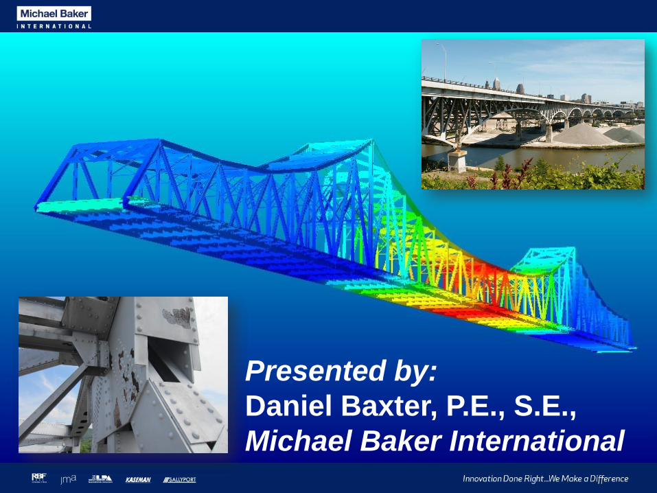
Presented by:
Daniel Baxter, P.E., S.E.,
Michael Baker International
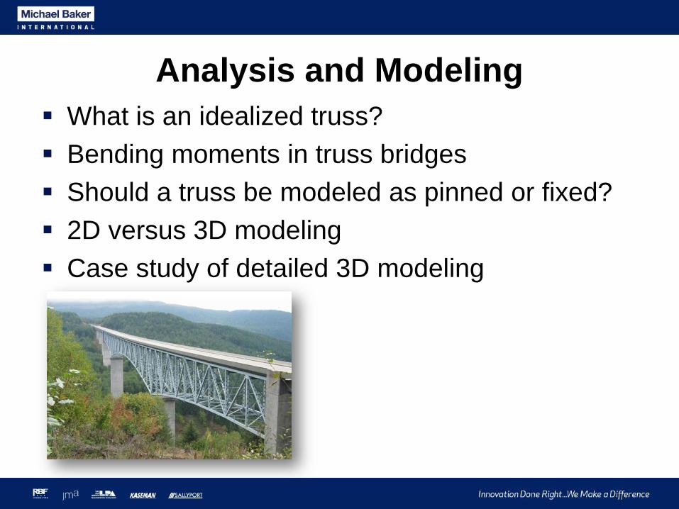
What is an idealized truss?
Bending moments in truss bridges
Should a truss be modeled as pinned or fixed?
2D versus 3D modeling
Case study of detailed 3D modeling
Analysis and Modeling?

What is an idealized truss? A truss is a structure composed of members joined
together at their endpoints. The members are joined
together by smooth pins and all loadings are applied
at the joints.
Each truss member acts as an axial force member,
subject to either axial tension or compression.
Source: Hibbeler, Structural Analysis, Fourth Edition, pp. 74.
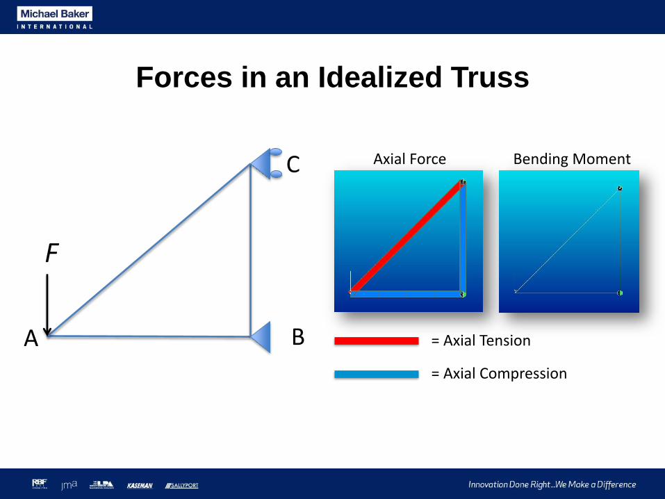
Forces in an Idealized Truss
F
A B
C
= Axial Tension
= Axial Compression
Axial Force Bending Moment

What happens when load is applied away
from a joint?
F
A B
C
= Axial Tension
= Axial Compression
Axial Force Bending Moment
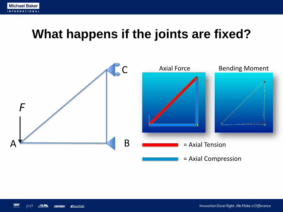
What happens if the joints are fixed?
F
A B
C
= Axial Tension
= Axial Compression
Axial Force Bending Moment

Primary Moments Primary moments are bending moments that the
truss members must develop to remain in equilibrium
while carrying load.
Since the truss is loaded away from the work point of
a joint, it is said to be eccentrically loaded.

Sources of Primary Moments
Worklines that don’t meet at a
single point
Centroid does not coincide with
the workline
Loads applied away from panel
points
Member self-weight

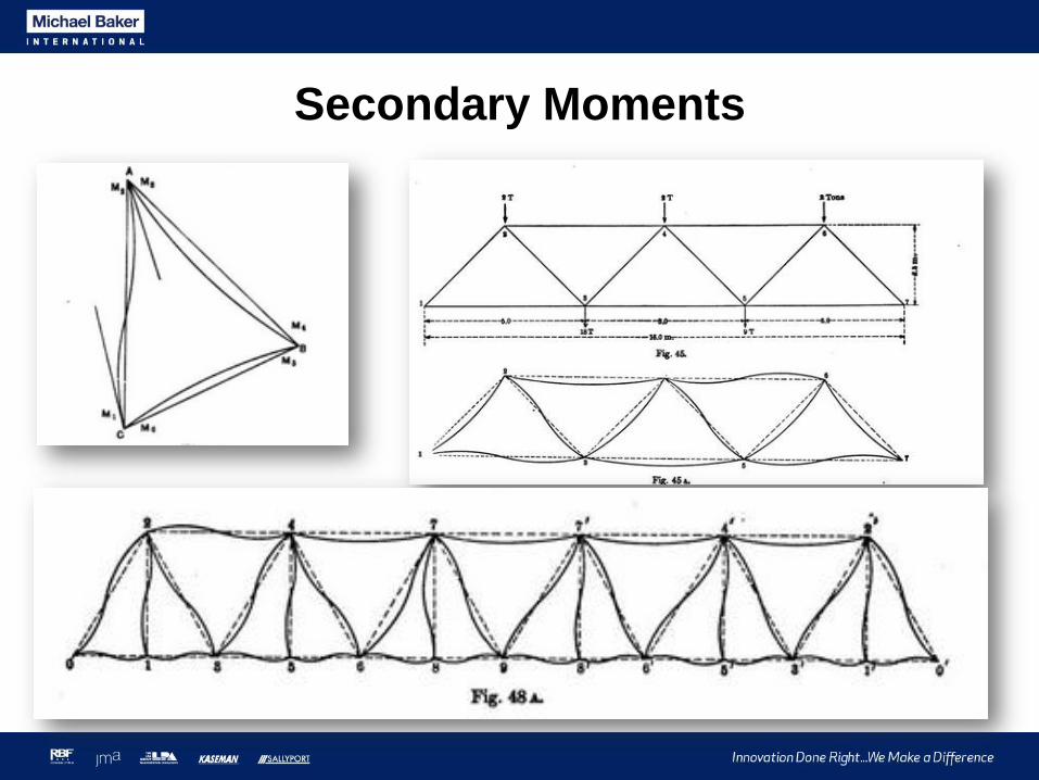
Secondary Moments Bending forces in truss members that are not
required to satisfy equilibrium are termed secondary
moments, or secondary stresses.
These are not the same as second order moments,
which are caused by axial forces applied to
compression members in their deflected position.

Sources of Secondary Moments
Rigid connections between members
Pinned Rigid
Secondary Moments

Should secondary moments be
considered for truss analysis?
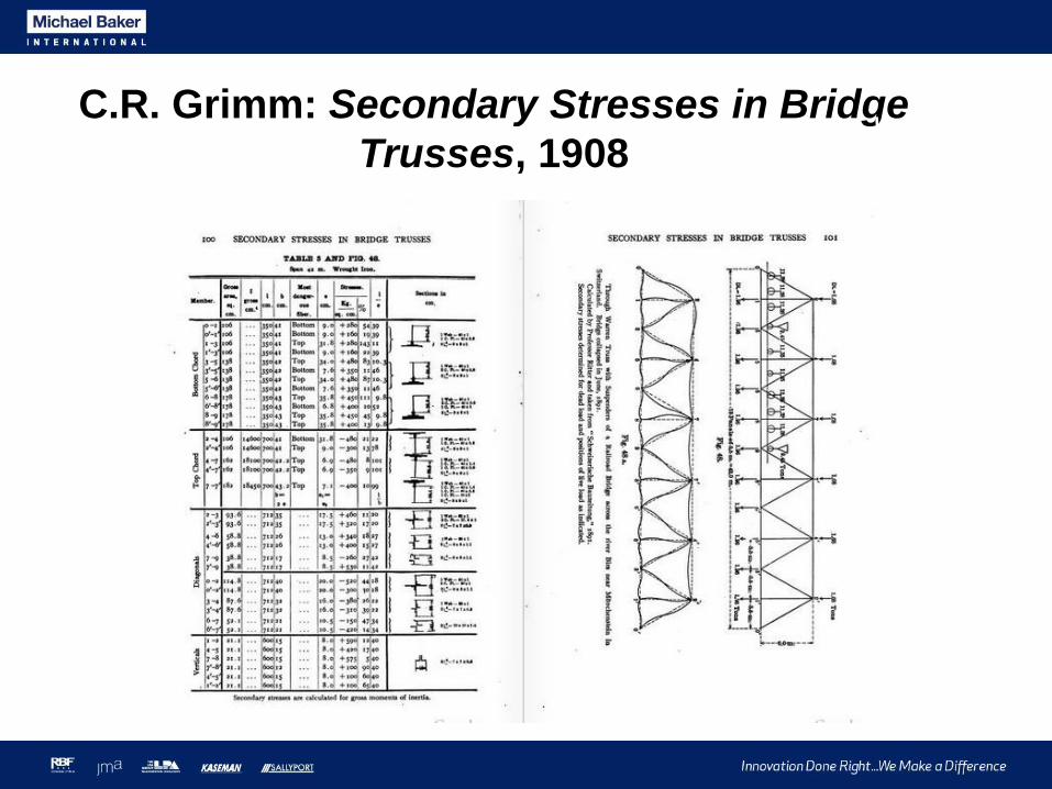
C.R. Grimm: Secondary Stresses in Bridge
Trusses, 1908

C.R. Grimm: Secondary Stresses in Bridge
Trusses, 1908
“In common cases there is no necessity for such
calculations, yet in particular cases secondary
stresses should be investigated;…where [they
are] of great magnitude, or where a bridge has to
carry much greater loads than those for which it
has been designed.”
“The writer suggests that readers who take a
particular interest in this subject…examine
trusses and publish their results”.

Sciotoville Bridge, 1916
Gustav Lindenthal
David Steinman
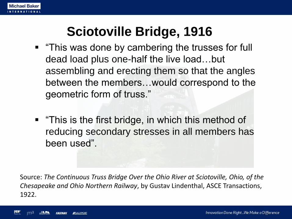
Sciotoville Bridge, 1916 “This was done by cambering the trusses for full
dead load plus one-half the live load…but
assembling and erecting them so that the angles
between the members…would correspond to the
geometric form of truss.”
“This is the first bridge, in which this method of
reducing secondary stresses in all members has
been used”.
Source: The Continuous Truss Bridge Over the Ohio River at Sciotoville, Ohio, of the Chesapeake and Ohio Northern Railway, by Gustav Lindenthal, ASCE Transactions, 1922.

J. Parcel and E. Murer: Effect of Secondary
Stresses Upon Ultimate Strength, 1934
J. Parcel and E. Murer: Effect of Secondary Stresses Upon Ultimate Strength, 1934
General analysis and laboratory tests
“For most bridge members…the ultimate strength is practically unaffected, even by high secondary stresses”.
“It is evident that the secondary bending was relieved by the plastic condition on the compressive face…A complete re-adjustment resulting in a nearly uniform distribution over the section was the final state of stress.”

R.M Korol, et al., On Primary and Secondary
Stresses in Triangulated Trusses, 1986
General analysis and laboratory tests
“It appears that Parcel and Murer’s work was
taken by the profession as the final word on the
subject of secondary stresses in steel trusses”.
“Continuity at the joints added 5% and 7% to the
carrying capacity of two trusses as computed by
simple statics”.

R.M Korol, et al., On Primary and Secondary
Stresses in Triangulated Trusses, 1986
Strength of pin-ended member with no eccentricity (no primary moment)
Strength of fixed-ended member with no eccentricity (no primary moment)
Strength decreases as eccentricity (primary moment) increases
Failure loads with no eccentricity

Current Practice “Where loads, other than the self-weight of the
members and wind loads there on, are transmitted to the truss at panel points, the truss may be analyzed as a pin-connected assembly”-AASHTO LRFD 4.6.2.4
“Stresses due to the dead load moment of the member shall be considered, as shall those caused by eccentricity of joints or working lines. Secondary stress due to truss distortion or floorbeamdeflection need not be considered in any member whose width measured parallel to the plane of distortion is less than one-tenth of its length.”-AASHTO LRFD 6.14.2.3
Current Practice
“[Secondary stresses] have little effect on the buckling strength (and tensile strength) of truss members.
Because of local yielding of extreme fibers of the members near the joints, the secondary moments gradually dissipate as the truss is loaded to its ultimate strength. They can therefore be neglected in the buckling analysis”
-Guide to Stability Design Criteria of Metal Structures, 6th
Edition, Page 50

Should trusses be modeled as pinned or fixed?
Pinned = secondary moments neglected
Fixed = secondary moments included
Recommend pinned for strength limit state, fixed for fatigue and service limit state
Include primary moments for all limit states
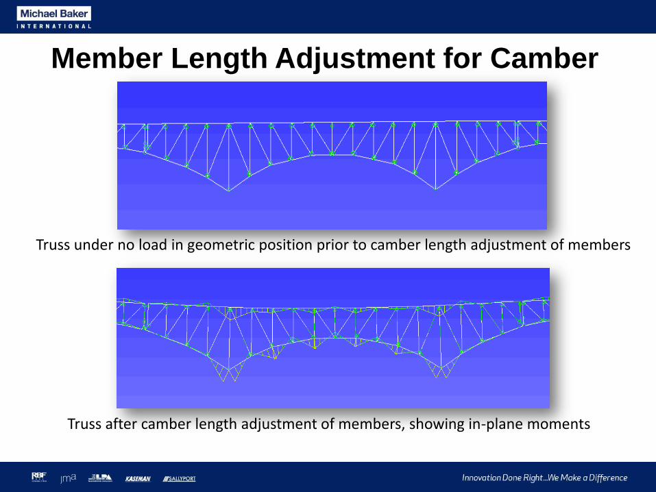
Member Length Adjustment for Camber
Truss under no load in geometric position prior to camber length adjustment of members
Truss after camber length adjustment of members, showing in-plane moments

How complex should the model be?
How complex should the model be?
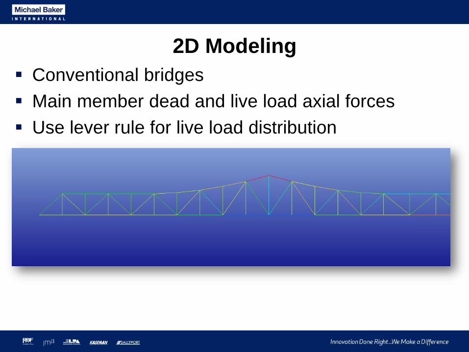
2D Modeling
Conventional bridges
Main member dead and live load axial forces
Use lever rule for live load distribution

3D Modeling
Wind analysis
Floor systems
Changes to structural configuration of original bridge
Detailed FEA of specific regions

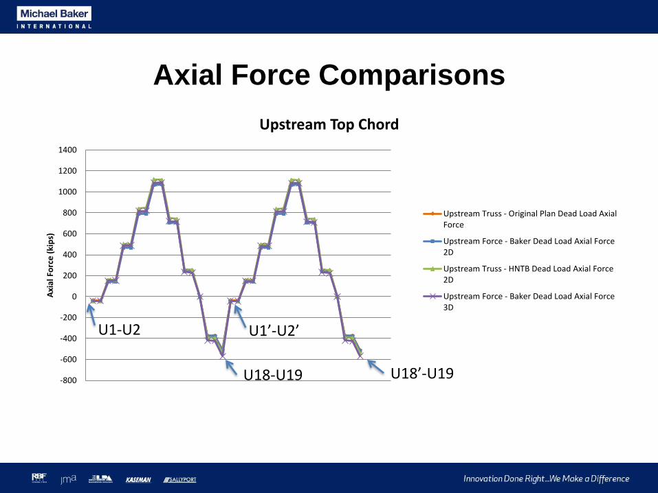
Axial Force Comparisons
Baker
Previous 2D Rating
Original Plan Forces
-800
-600
-400
-200
0
200
400
600
800
1000
1200
1400
Axi
al F
orc
e (
kip
s)
Upstream Top Chord
Upstream Truss - Original Plan Dead Load AxialForce
Upstream Force - Baker Dead Load Axial Force2D
Upstream Truss - HNTB Dead Load Axial Force2D
Upstream Force - Baker Dead Load Axial Force3D
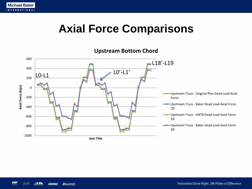
Axial Force Comparisons
U1-U2 U1’-U2’
U18-U19 U18’-U19
-1000
-800
-600
-400
-200
0
200
400
600
Axi
al F
orc
e (
kip
s)
Axis Title
Upstream Bottom Chord
Upstream Truss - Original Plan Dead Load AxialForce
Upstream Truss - Baker Dead Load Axial Force2D
Upstream Truss - HNTB Dead Load Axial Force2D
Upstream Truss - Baker Dead Load Axial Force3D
L0-L1L0’-L1’
L18’-L19
Axial Force Comparisons

Wind Load Moments
-2376 k-ft -3125 k-ft
-1920 k-ft -2703 k-ft
-3125 / -2376 = 1.32
-2703 / -1920 = 1.41
Linear Results Geometric Nonlinear Results

Floor Systems in 3D

Floor System Deformations
Floorbeam
Stringers
Tie Girder
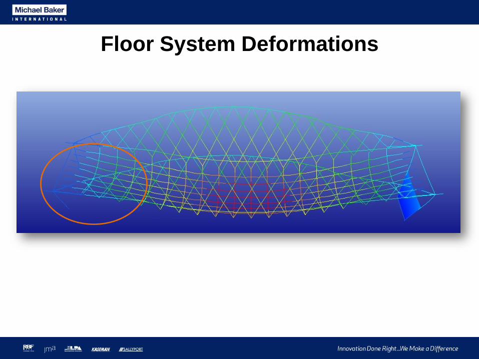
Floor System Deformations
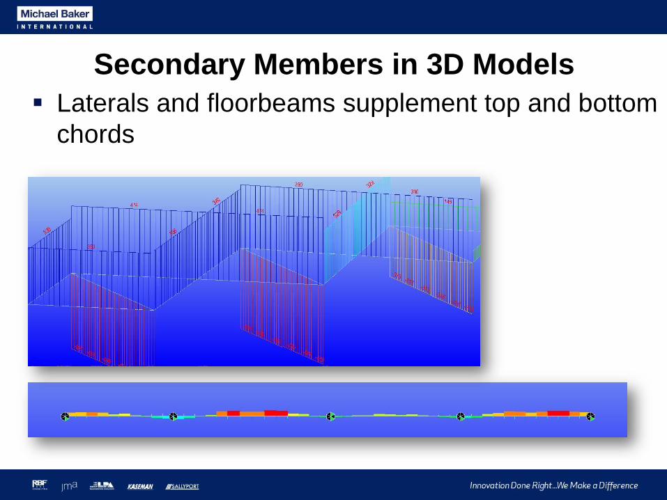
Secondary Members in 3D Models
Laterals and floorbeams supplement top and bottom
chords

Boundary Conditions in 3D Models
Consider ability of actual connections to transfer
moments
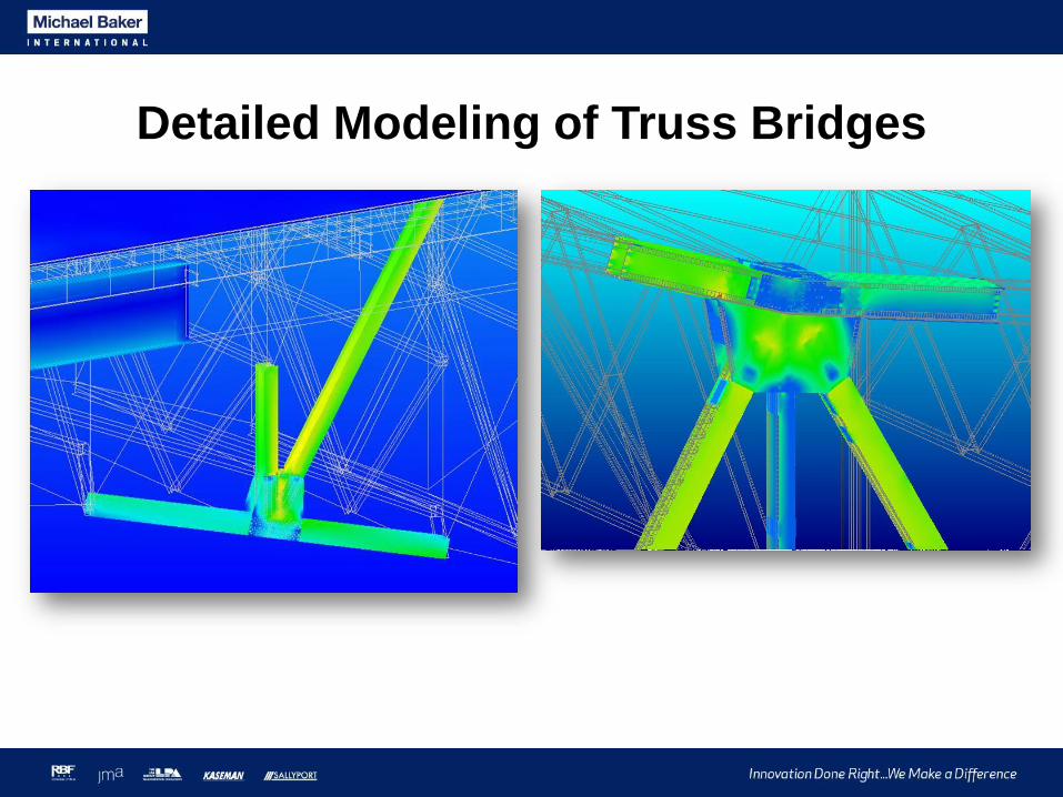
Detailed Modeling of Truss Bridges

Detailed Modeling Case Study:
Winona Bridge

U13-L14, adjoining connections and members
modeled with shell elements
High-strength bars for U13-L14 modeled with
truss elements
Rivets modeled with beam elements and
multilinear links

U13
L14
Questions:• What are the demand/capacity ratios in adjacent
members after one channel fractures?
• Will there be large differential displacements between the end of the member and the connection?
• Will rivets in the gusset plates fail due to large differential displacements between the member and connection?
• Will the high-strength bars engage to carry load after one channel fractures?

Three analysis conditions:
• 1.25DC + 1.5DW + 1.30(90% Double Truck LL + IM)
[Extreme III] before fracture
• Extreme III after one U13-L14 channel fractures
• Extreme III after both channels fracture

U13
L140, 0
0.05, 22
0.2, 30 0.25, 30.5
0
5
10
15
20
25
30
35
0 0.05 0.1 0.15 0.2 0.25 0.3
She
ar (
kip
s)
Deformation (in)
Shear Versus Deformation for A-141 Rivets
Source: The Static Strength of Rivets Subjected to Combined Tension and Shear, Munse, et. al., University of Illinois Bulletin, 1956
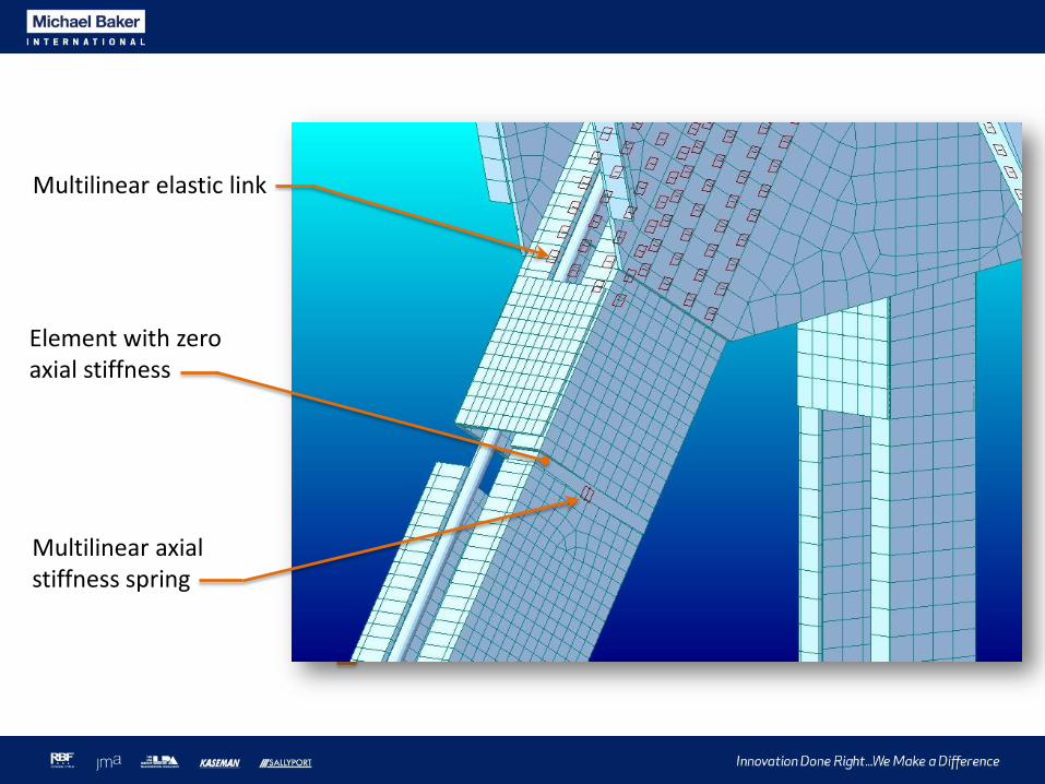
U13
L14
Element with zero axial stiffness
Multilinear axial stiffness spring
Multilinear elastic link
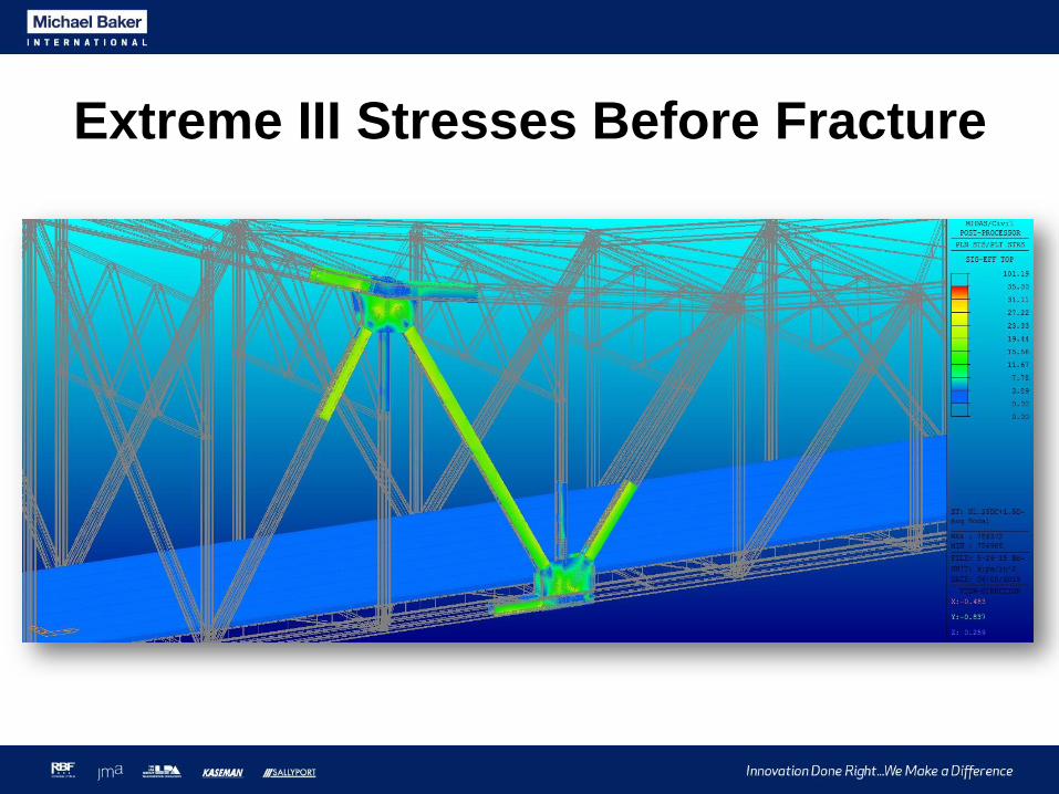
Extreme III Stresses Before Fracture
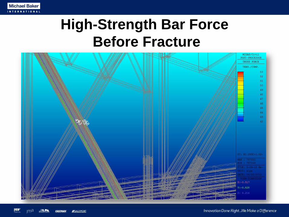
High-Strength Bar Force
Before Fracture

0, 0
0.05, 22
0.2, 30 0.25, 30.5
0
5
10
15
20
25
30
35
0 0.05 0.1 0.15 0.2 0.25 0.3
She
ar (
kip
s)
Deformation (in)
Rivet Shear Versus Deformation Before Fracture
Maximum rivet shear = 18.7 kips

Extreme III Stresses After Fracture

Extreme III Stresses After Fracture
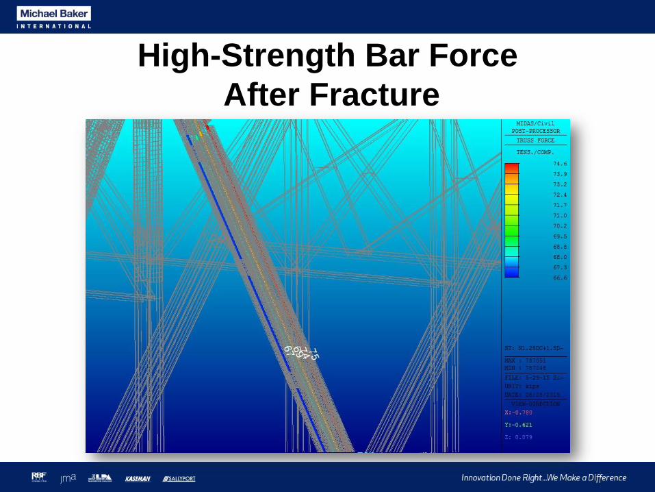
High-Strength Bar Force
After Fracture

Axial Force Distribution After Fracture
High Strength Bars Remaining Channel
Force 285 kips 500 kips
Percent of Total Force
36% 64%
Percent of Total Area
31% 69%

Deformations After Fracture

Deformations After Fracture

0, 0
0.05, 22
0.2, 30 0.25, 30.5
0
5
10
15
20
25
30
35
0 0.05 0.1 0.15 0.2 0.25 0.3
She
ar (
kip
s)
Deformation (in)
Rivet Shear Versus Deformation After Fracture
Maximum rivet shear = 21.9 kips
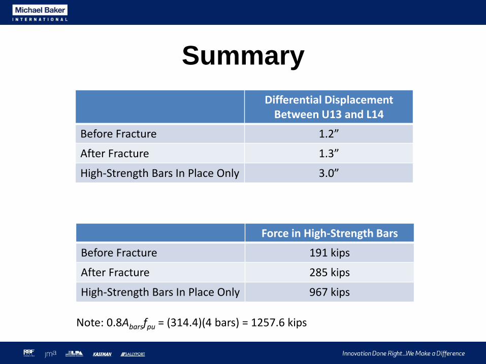
Summary
Differential Displacement Between U13 and L14
Before Fracture 1.2”
After Fracture 1.3”
High-Strength Bars In Place Only 3.0”
Force in High-Strength Bars
Before Fracture 191 kips
After Fracture 285 kips
High-Strength Bars In Place Only 967 kips
Note: 0.8Abarsfpu = (314.4)(4 bars) = 1257.6 kips

Summary
U13-L14 Longitudinal Strain
Before Fracture 0.0007
After Fracture 0.001
High-Strength Bars In Place Only 0.003
Note: (0.8fpu) / Ebar = 0.004

Summary

Summary
Maximum Rivet Force
Maximum Rivet Displacement
Before Fracture 18.7 kips 0.042”
After Fracture 21.9 kips 0.050”
High Strength Bars In Place Only 16.5 kips 0.037”
0, 0
0.05, 22
0.2, 30 0.25, 30.5
0
5
10
15
20
25
30
35
0 0.05 0.1 0.15 0.2 0.25 0.3
She
ar (
kip
s)
Deformation (in)
Shear Versus Deformation for A-141 Rivets
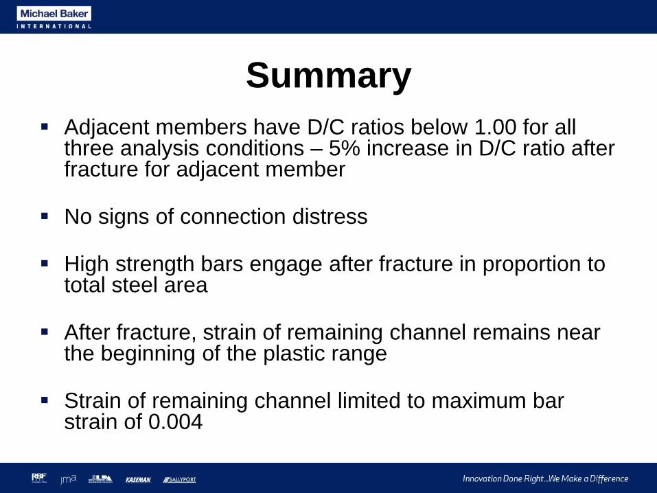
Summary
Adjacent members have D/C ratios below 1.00 for all three analysis conditions – 5% increase in D/C ratio after fracture for adjacent member
No signs of connection distress
High strength bars engage after fracture in proportion to total steel area
After fracture, strain of remaining channel remains near the beginning of the plastic range
Strain of remaining channel limited to maximum bar strain of 0.004

Conclusions
Use pinned ends for the strength limit state
Consider primary moments
2D analysis is sufficient for main members of most
truss bridges
Use 3D when appropriate
Be consistent with analysis and design in 3D!
Consider detailed modeling in 3D when needed

Special Elite Engineers Webinar Sequence An Insider’s Perspective
To receive your PDH credit send an email to the address
below with the subject header ‘July Webinar PDH’.
PDH Credit

Special Elite Engineers Webinar Sequence An Insider’s Perspective
For any additional inquiries and interest in trying out midas Civil please contact us at:
Questions?

Special Elite Engineers Webinar Sequence An Insider’s Perspective
For any additional inquiries and interest in trying out midas Civil please contact us:
MIDASoft
Thank you!