spec-tech-sales october, 27, 2015
TRANSCRIPT

Page 1 of 5
Operations & Maintenance Manuals
HWBT-1 Heating Water System Buffer Tank Specification Section # 23 2113 – Hydronic Specialties
Project Name and Owner: Kelly Walsh High School 3500 East 12’th Street Natrona County School District # 1 Casper, Wyoming 82609 Architect: RB+B Architects Fort Collins, Colorado Mechanical Engineer: Engineering Design Associates Casper, Wyoming Mechanical Contractor: KK Mechanical Roy, Utah Sheet Metal Contractor: North Star HVAC West Haven, Utah Controls Contractor: Johnson Controls Casper, Wyoming Wholesale Distributor: Ferguson Enterprises Mills, Wyoming
Spec-Tech-Sales October, 27, 2015 Integrated Boiler Room Solutions Commercial Technical Sales and Service For the Rocky Mountain Region 14652 West Vassar Drive
Lakewood, CO 80228 Colorado Phone 720-259-0718 Fax 720-204-2274
Wyoming Phone 307-222-7559 Fax 307-200-4068
Website: www.spec-tech-sales.com

Page 2 of 5
Green Boiler Technologies Heating Water Buffer Tank
Specified – Basis of Design BASED UPON 100% FINAL CONSTRUCTION DRAWINGS & SPECIFICATIONS
100% Construction Drawings & Documents Issue Date May 12, 2014 Schedule Tag: HWBT-1 Heating Water Buffer Tank Specification Section # 23 2113 Hydronic Specialties Also Reference: Specification Section # 23 5225 Gas Fired Packaged Condensing Boilers – Separate Submittal Package Specification Section # 22 3000 Plumbing Equipment – Separate Submittal Package Specification Section # 23 5100 Vent Stacks – Separate Submittal Package -And- Specification Section # 01 1600 Product Requirements Specification Section # 23 0593 Testing Adjusting & Balancing Specification Section # 23 0800 Commissioning of HVAC System Specification Section # 23 0900 Building Automation System Specification Section # 23 2500 HVAC Water Treatment Specification Section # 23 2113 Hydronic Piping Specification Section # 23 2114 Hydronic Specialties – Other Material Specification Section # 23 2123 Hydronic Pumps Scope Primarily Provided By Others - Listed For Coordination Purposes
Green Boiler Technologies Heating Water Buffer Tank – Scope of Supply
Tag: HWBT-1_Heating Water Boiler Side Buffer Tank Assembly
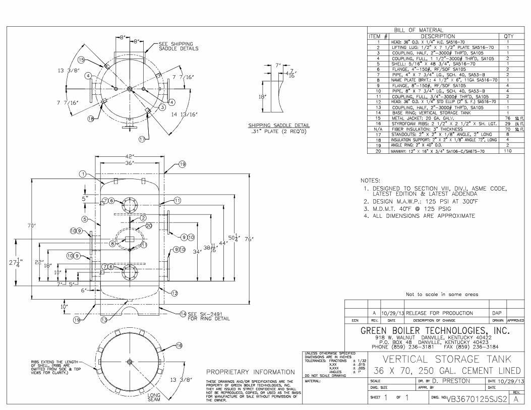
Lot package consisting of (1) each Green Boiler Technologies model # VB36701250JSL heating system cement lined steel lined buffer tank assembly vertical jacketed and insulated 250-gallon capacity ASME section VIII division 1 listing and certification for maximum allowable 125-PSI operating pressure as required. Tank shall be manufactured and MODIFIED with (6) each total flanged supply and return connections between (2) each 8” diameter 150 # flanged supply and return boiler loop side, (2) each 8” diameter 150 # flanged supply and return system loop side and (2) each 4” diameter 150 # flanged supply and return domestic loop side water with applicable controls and sensors. The buffer tank to also include: internal tank baffle assembly. The buffer tank to also include applicable tank tapping’s for the included (1) each Patterson-Kelley operating temperature sensor for connection back to the defined Master Patterson-Kelley MACH C-4000 boiler - to be daisy chained together with the other 3 boilers – NOTE: Must explore alternate strategy if the Heat Timer Multi-Mod Platinum with BACnet boiler staging / sequencing control panel assembly (must confirm intent reference mechanical controls drawing # 6.M900 – building heating water system control diagram and sequence of operation). Package to include deep well for lead / lag staging and rotation control of set point temperature. Lot package to also include (1) each high limit aquastat with manual reset, (1) each tank air vent, (1) each tank drain, and (1) each tank thermometer to be field installed by others.

Page 3 of 5
NOTE: Must add for and coordinate installation with the BP-1 thru BP-4 scheduled self-
contained variable speed drive boiler pumps, HWP-1 and HWP-2 scheduled variable
speed system pumps with VSD’s, GP-1 scheduled glycol pump and RCP-1, RCP-2 and
RCP-3 domestic side pumps and applicable ET-1.1, ET-1.2, ET-2 heating system
expansion tanks, ET-3 domestic side expansion tank, miscellaneous air separation / air
vents, thermostatic mixing valves etc… which are NOT part of this scope of supply.
We would recommend a heat trap / heat sink on the boiler side piping loop between the HWBT-1 buffer tank along with either a weighted gravity style check valve or a spring loaded check valve – provided and installed by others to help prevent any potential migrant heat from the buffer tank loop inadvertently drifting through the HX-1 and HX-2 domestic water heat exchangers / hot water generator assemblies.
All interconnecting piping – valves and additional accessories not listed to be provided and field installed by others.
Project Specific Wiring for HX-1 & HX-2 Patterson Kelley Duration Water Heater
Modified Customer Electrical Connections – PRELIMINARY SUBJECT TO CHANGE
TERMINAL # FU1- Connect Line 1 from single phase 208-240. Jumper from TERMINAL # FU1 to
TERMINAL # FU2. Jumper downstream from Fuse#1 to TERMINAL # 9.
TERMINAL #FU3- Connect Line 2 from single phase 208-240.
TERMINAL #1- Connect Neutral line from single phase 208-240 with Jumper from TERMINAL # 1
to TERMINAL # 6.
TERMINAL # 3- Connect Ground from single phase 208-240.
TERMINAL #7- Jumper from TERMINAL #7 to TERMINAL #8.
Green Boiler Technologies / Sellers diversified manufacturer of high and low pressure steam
and water fire tube and immersion fired boilers, dearators – boiler feed systems, surge - transfer tanks,
condensate return units, blow down separators, high efficiency and high performance condensing
boilers and direct fired water heaters, stack economizers / heat recovery units, indirect domestic water
storage heaters, semi-instantaneous domestic water heaters, and boiler and chilled water buffer
tanks for a broad range of light commercial, and commercial heating, institutional, process, and
domestic water heating applications.
Direct immersion fired - individual nozzles high pressure and low pressure steam and water fire tube ( XID rifled fire tube option ) 1 or 2-pass boilers for superior performance – rugged & low maintenance
Page 4 of 5
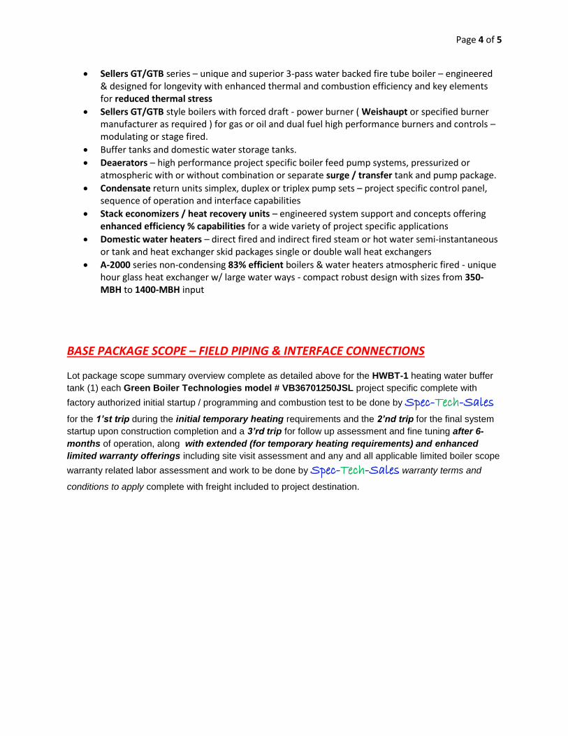
Sellers GT/GTB series – unique and superior 3-pass water backed fire tube boiler – engineered & designed for longevity with enhanced thermal and combustion efficiency and key elements for reduced thermal stress
Sellers GT/GTB style boilers with forced draft - power burner ( Weishaupt or specified burner manufacturer as required ) for gas or oil and dual fuel high performance burners and controls – modulating or stage fired.
Buffer tanks and domestic water storage tanks.
Deaerators – high performance project specific boiler feed pump systems, pressurized or atmospheric with or without combination or separate surge / transfer tank and pump package.
Condensate return units simplex, duplex or triplex pump sets – project specific control panel, sequence of operation and interface capabilities
Stack economizers / heat recovery units – engineered system support and concepts offering enhanced efficiency % capabilities for a wide variety of project specific applications
Domestic water heaters – direct fired and indirect fired steam or hot water semi-instantaneous or tank and heat exchanger skid packages single or double wall heat exchangers
A-2000 series non-condensing 83% efficient boilers & water heaters atmospheric fired - unique hour glass heat exchanger w/ large water ways - compact robust design with sizes from 350-MBH to 1400-MBH input
BASE PACKAGE SCOPE – FIELD PIPING & INTERFACE CONNECTIONS Lot package scope summary overview complete as detailed above for the HWBT-1 heating water buffer
tank (1) each Green Boiler Technologies model # VB36701250JSL project specific complete with
factory authorized initial startup / programming and combustion test to be done by Spec-Tech-Sales
for the 1’st trip during the initial temporary heating requirements and the 2’nd trip for the final system
startup upon construction completion and a 3’rd trip for follow up assessment and fine tuning after 6-
months of operation, along with extended (for temporary heating requirements) and enhanced
limited warranty offerings including site visit assessment and any and all applicable limited boiler scope
warranty related labor assessment and work to be done by Spec-Tech-Sales warranty terms and
conditions to apply complete with freight included to project destination.
Page 5 of 5
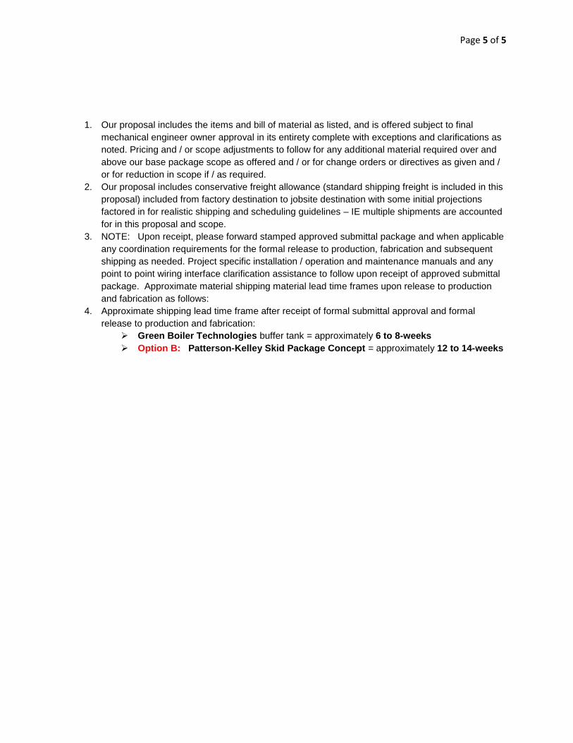
1. Our proposal includes the items and bill of material as listed, and is offered subject to final
mechanical engineer owner approval in its entirety complete with exceptions and clarifications as
noted. Pricing and / or scope adjustments to follow for any additional material required over and
above our base package scope as offered and / or for change orders or directives as given and /
or for reduction in scope if / as required.
2. Our proposal includes conservative freight allowance (standard shipping freight is included in this
proposal) included from factory destination to jobsite destination with some initial projections
factored in for realistic shipping and scheduling guidelines – IE multiple shipments are accounted
for in this proposal and scope.
3. NOTE: Upon receipt, please forward stamped approved submittal package and when applicable
any coordination requirements for the formal release to production, fabrication and subsequent
shipping as needed. Project specific installation / operation and maintenance manuals and any
point to point wiring interface clarification assistance to follow upon receipt of approved submittal
package. Approximate material shipping material lead time frames upon release to production
and fabrication as follows:
4. Approximate shipping lead time frame after receipt of formal submittal approval and formal
release to production and fabrication:
Green Boiler Technologies buffer tank = approximately 6 to 8-weeks
Option B: Patterson-Kelley Skid Package Concept = approximately 12 to 14-weeks
Submittal data sheets can ONLY be ordered as a “Submittal Data Sheet Pack”, using MC# 4400. They are not available to order on an individual basis, however each data sheet is available on the AMTROL Web Site and can be downloaded and printed for use as needed. For the most updated technical specifications, please download sheet at www.amtrol.com
Rev. 04/11
Job Name ____________________________________________
Location ____________________________________________
____________________________________________
____________________________________________
Engineer ____________________________________________
Contractor ___________________________________________
Contractor P.O. No. __________________________________
Sales Representative __________________________________
Model No. Ordered __________________________________
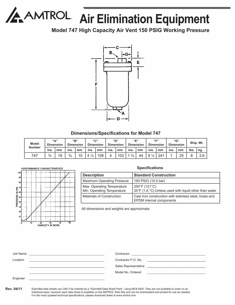
Air Elimination EquipmentModel 747 High Capacity Air Vent 150 PSIG Working Pressure
Model Number
“A” Dimension
“B” Dimension
“C” Dimension
“D” Dimension
“E” Dimension
“F” Dimension
“G” Dimension Ship. Wt.
ins. mm ins. mm ins. mm ins. mm ins. mm ins. mm ins. mm lbs. kg.
747 ¾ 19 ⅜ 10 4 ¼ 108 4 102 1 ¾ 44 9 ½ 241 1 25 8 3.6
Description Standard ConstructionMaximum Operating Pressure 150 PSIG (10.5 bar)Max. Operating Temperature Min. Operating Temperature
250°F (121°C) 35°F (1.6.°C) Unless used with liquid other than water
Materials of Construction Cast Iron construction with stainless steel, brass and EPDM internal components
All dimensions and weights are approximate.
Dimensions/Specifications for Model 747
Specifications

PRODUCT DATA
60-2104�10
L4006,7,8; L6006,7,8 Aquastat® Controllers
GENERALAquastat® Controllers are immersion type devices for limiting or regulating the temperature of liquids in boilers, storage tanks, and other applications where temperature control is required.
FEATURES� L4006, 7, and 8 provide Spst switching for high or low
limit or circulator control.� L4006G includes two Spst switches that provide high
limit and circulator control.� L4006,7; L6006,7 models are available for insertion in:
vertical or horizontal immersion well, vertical or horizontal direct immersion, and surface mounting.
� L4008, L6008 include remote bulb for mounting controller at a location away from the sensing element.
� Totally enclosed Micro Switch� snap-acting switches operate on temperature rise to set point.
� Models calibrated for high limit use are also suitable for low limit control if a separate high limit controller is used.
� Visible control point scale and external adjustment screw, permit easy setting.
� Remote bulb models may be used to sense air temperature in ducts and in outside air sensing applications.
FOR VERTICALMOUNTING ANDHORIZONTALSENSORINSERTION
FOR SURFACEMOUNTING WITH REMOTE BULB
ContentsGeneral ............................................................................. 1Features ........................................................................... 1Specifications ................................................................... 2Ordering Information ........................................................ 2Installation ........................................................................ 8Operation .......................................................................... 14Adjustments ...................................................................... 15Checkout .......................................................................... 17Material Safety Data Sheet .............................................. 18

L4006,7,8; L6006,7,8 AQUASTAT® CONTROLLERS
60-2104�10 2
ORDERING INFORMATIONWhen purchasing replacement and modernization products from your TRADELINE® wholesaler or distributor, refer to the TRADELINE® Catalog or price sheets for complete ordering number.
If you have additional questions, need further information, or would like to comment on our products or services, please write or phone:
1. Your local Honeywell Automation and Control Products Sales Office (check white pages of your phone directory).2. Honeywell Customer Care
1885 Douglas Drive NorthMinneapolis, Minnesota 55422-4386
In Canada�Honeywell Limited/Honeywell Limitée, 35 Dynamic Drive, Scarborough, Ontario M1V 4Z9.International Sales and Service Offices in all principal cities of the world. Manufacturing in Australia, Canada, Finland, France, Germany, Japan, Mexico, Netherlands, Spain, Taiwan, United Kingdom, U.S.A.
SPECIFICATIONSIMPORTANT
The specifications given in this publication do not include normal manufacturing tolerances. Therefore, this unit may not exactly match the listed specifications. Also, this product is tested and calibrated under closely controlled conditions, and some minor differences in performance can be expected if those conditions are changed.
SUPER TRADELINE®/TRADELINE MODELSSUPER TRADELINE controls offer features not available on TRADELINE or standard models, and are designed to replace a wide range of Honeywell and competitive controls.
TRADELINE models are selected and packaged to provide ease of stocking, ease of handling, and maximum replacement value. Specifications of SUPER TRADELINE and TRADELINE controls are the same as those of standard models except as noted below.
SUPER TRADELINE Model: L6006A Aquastat Controller.
SUPER TRADELINE Features:SUPER TRADELINE package with cross reference label and
special instructions.Factory-set stop at 240° F (116° C).Vertical or horizontal mount.Tube of heat-conductive compound.Insulation: 1-1/2 in. to 3 in. (38 mm to 76 mm).
TRADELINE Models: L4006A,B,E; L4008E; L6006C; L6008A Aquastat Controllers.
TRADELINE Features Available:TRADELINE package with cross reference label and special
instructions.Some TRADELINE models include immersion well.Factory-set stops at 180° F, 240° F, or 250° F (82° C, 116° C,
or 121° C).Vertical or horizontal mount.Tube of heat-conductive compound.Insulation depths of 1-1/2 in. or 3 in. (38 or 76 mm).
NOTE: The following specifications are standard. Variances, available as options, are listed in Tables 1 and 2.
Electrical Ratings (A):Models with 2° F (1° C) fixed differential:
Models with 5° F (3° C) fixed differential or 5° F to 30° F (3° C to 17° C) adjustable differential:
a L6008G only.
Switching:L4006, L4007, L4008: Spst.L6006, L6007, L6008: Spdt (breaks R-B and makes R-W on
temperature rise at setpoint).
Pressure Rating: Capillary Bulb (Direct Immersion): 200 psi (1379 kPa). Immersion Well: 255 psi (1758 kPa).
Sensing Bulb Material: Copper.
Sensing Bulb Fill: Liquid�toluene or silicone oil.
Sensing Bulb Dimensions: 2-7/8 in. (73 mm) long, 3/8 in. (10 mm) diameter.
Wiring: Screw terminals.
Maximum Ambient Temperature: 150° F (66° C).
120 Vac 240 VacFull Load 2.6 1.3Locked Rotor 15.6 7.8
110/120 Vac 200/240 Vac 277 Vaca
Full Load 8.0 5.1 4.2Locked Rotor 48.0 30.6 25.2Millivoltage 0.25 at 0.25 to 12 Vdc
L4006,7,8; L6006,7,8 AQUASTAT® CONTROLLERS
3 60-2104�10
Approvals:Underwriters Laboratories Inc:Remote bulb devices and well-mounted devices shipped
without well are component recognized: File No. MP466, Guide No. MBPR2.
L4006A shipped with well, L4006G, L4007A,B; L6006C for surface mounting, L6006B for direct immersion mounting, and L6007A are listed: File No. MP466, Guide No. MBPR.
L6008G is listed: File No. E4436, Guide No. XAPX.Canadian Standards Association: File No. LR1620,
Guide No. 400-E-O.
ANSI Miswiring: Models with 1/4 in. (6.35 mm) tab terminal meet ANSI Appliance Miswiring Standard.
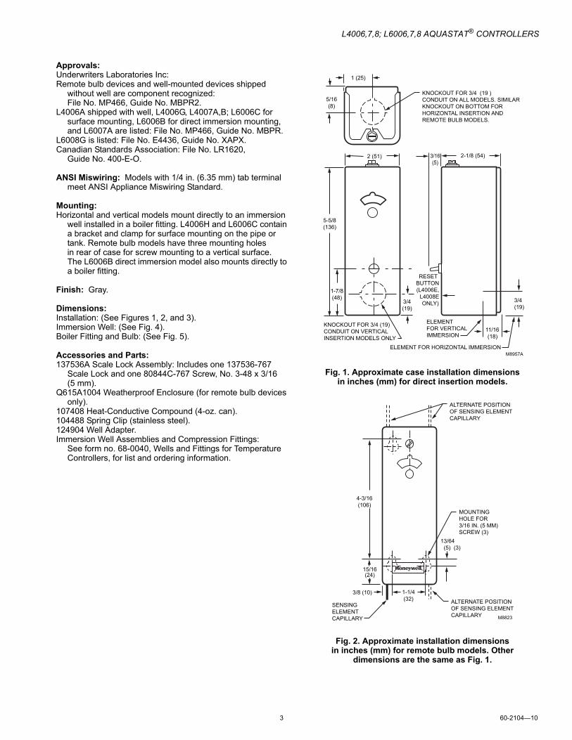
Mounting: Horizontal and vertical models mount directly to an immersion
well installed in a boiler fitting. L4006H and L6006C contain a bracket and clamp for surface mounting on the pipe or tank. Remote bulb models have three mounting holes in rear of case for screw mounting to a vertical surface. The L6006B direct immersion model also mounts directly to a boiler fitting.
Finish: Gray.
Dimensions:Installation: (See Figures 1, 2, and 3).Immersion Well: (See Fig. 4).Boiler Fitting and Bulb: (See Fig. 5).
Accessories and Parts: 137536A Scale Lock Assembly: Includes one 137536-767
Scale Lock and one 80844C-767 Screw, No. 3-48 x 3/16(5 mm).
Q615A1004 Weatherproof Enclosure (for remote bulb devices only).
107408 Heat-Conductive Compound (4-oz. can).104488 Spring Clip (stainless steel). 124904 Well Adapter.Immersion Well Assemblies and Compression Fittings:
See form no. 68-0040, Wells and Fittings for Temperature Controllers, for list and ordering information.
Fig. 1. Approximate case installation dimensions in inches (mm) for direct insertion models.
Fig. 2. Approximate installation dimensions in inches (mm) for remote bulb models. Other
dimensions are the same as Fig. 1.
M8957A
KNOCKOUT FOR 3/4 (19 )CONDUIT ON ALL MODELS. SIMILARKNOCKOUT ON BOTTOM FOR HORIZONTAL INSERTION AND REMOTE BULB MODELS.
1 (25)
5/16(8)
2 (51) 2-1/8 (54)
5-5/8(136)
1-7/8(48)
3/16(5)
RESET BUTTON(L4006E,
L4008EONLY)
KNOCKOUT FOR 3/4 (19) CONDUIT ON VERTICAL INSERTION MODELS ONLY
ELEMENT FOR HORIZONTAL IMMERSION
3/4(19)
ELEMENT FOR VERTICAL IMMERSION
11/16(18)
3/4(19)
SENSINGELEMENTCAPILLARY
3/8 (10) 1-1/4(32) ALTERNATE POSITION
OF SENSING ELEMENTCAPILLARY
13/64 (5) (3)
MOUNTINGHOLE FOR3/16 IN. (5 MM)SCREW (3)
15/16(24)
4-3/16(106)
ALTERNATE POSITIONOF SENSING ELEMENTCAPILLARY
M8823

L4006,7,8; L6006,7,8 AQUASTAT® CONTROLLERS
60-2104�10 4
Fig. 3. Approximate installation dimensions in inches (mm) for surface mount models.
Fig. 4. Approximate immersion well dimensions in inches (mm) for all models except L4006C and L6006B.
Fig. 5. Approximate boiler fitting and bulb dimensions in inches (mm) for L4006C and L6006B.
M8958A
7/8 IN. (22 MM) STANDARDKNOCKOUT (2)
1 (25)
2 (51)
5-5/8(136)
2-3/4 (70)2 (51)
CL
1/2 — 14 IN. NPT
7/16(11)
3 (76)1-1/2 (38) M8789A
1/2 OR 3/4 — 14 IN. NPT
3/8(10)
3 (76)1-5/16 (33) M8799A
L4006,7,8; L6006,7,8 AQUASTAT® CONTROLLERS
5 60-2104�10
Standard Models:L4006,A,B,C,E,G; L4007,A,B; L4008A,B.E; L6006A,B,C; L6007A, L6008,A,G,H
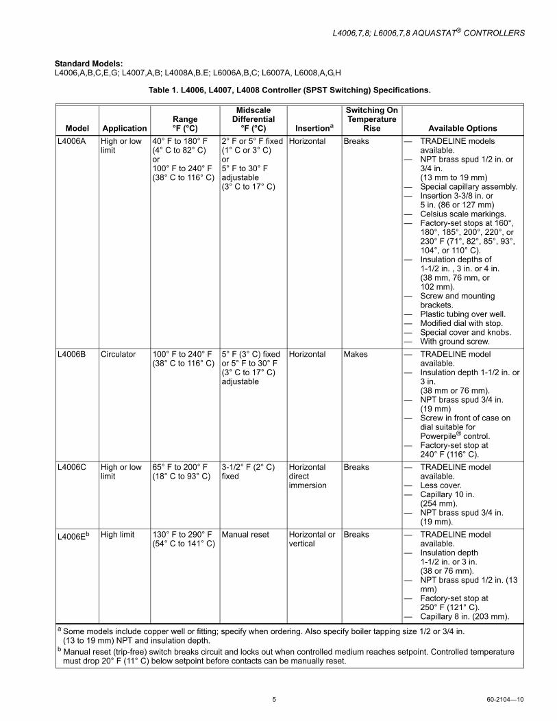
Table 1. L4006, L4007, L4008 Controller (SPST Switching) Specifications.
Model ApplicationRange°F (°C)
Midscale Differential
°F (°C) Insertiona
Switching On Temperature
Rise Available OptionsL4006A High or low
limit40° F to 180° F(4° C to 82° C)or100° F to 240° F(38° C to 116° C)
2° F or 5° F fixed (1° C or 3° C)or5° F to 30° Fadjustable(3° C to 17° C)
Horizontal Breaks � TRADELINE models available.
� NPT brass spud 1/2 in. or 3/4 in. (13 mm to 19 mm)
� Special capillary assembly.� Insertion 3-3/8 in. or
5 in. (86 or 127 mm)� Celsius scale markings.� Factory-set stops at 160°,
180°, 185°, 200°, 220°, or 230° F (71°, 82°, 85°, 93°, 104°, or 110° C).
� Insulation depths of 1-1/2 in. , 3 in. or 4 in. (38 mm, 76 mm, or 102 mm).
� Screw and mounting brackets.
� Plastic tubing over well.� Modified dial with stop.� Special cover and knobs.� With ground screw.
L4006B Circulator 100° F to 240° F (38° C to 116° C)
5° F (3° C) fixed or 5° F to 30° F (3° C to 17° C) adjustable
Horizontal Makes � TRADELINE model available.
� Insulation depth 1-1/2 in. or 3 in. (38 mm or 76 mm).
� NPT brass spud 3/4 in. (19 mm)
� Screw in front of case on dial suitable for Powerpile® control.
� Factory-set stop at 240° F (116° C).
L4006C High or low limit
65° F to 200° F (18° C to 93° C)
3-1/2° F (2° C) fixed
Horizontal direct immersion
Breaks � TRADELINE model available.
� Less cover.� Capillary 10 in.
(254 mm).� NPT brass spud 3/4 in.
(19 mm).
L4006Eb High limit 130° F to 290° F (54° C to 141° C)
Manual reset Horizontal or vertical
Breaks � TRADELINE model available.
� Insulation depth 1-1/2 in. or 3 in. (38 or 76 mm).
� NPT brass spud 1/2 in. (13 mm)
� Factory-set stop at 250° F (121° C).
� Capillary 8 in. (203 mm).a Some models include copper well or fitting; specify when ordering. Also specify boiler tapping size 1/2 or 3/4 in.
(13 to 19 mm) NPT and insulation depth.b Manual reset (trip-free) switch breaks circuit and locks out when controlled medium reaches setpoint. Controlled temperature
must drop 20° F (11° C) below setpoint before contacts can be manually reset.

L4006,7,8; L6006,7,8 AQUASTAT® CONTROLLERS
60-2104�10 6
L4006G High limit and circulator control
100° F to 200° F (38° C to 93° C)
10° F (6° C) fixed Horizontal Two switches break simultaneously
� External adjustment knob.� Insulation depth 4 in.
(102 mm).� Factory-set stop at
160° F (71° C).� Celsius scale markings.� Without well.
L4007A High or low limit
100° F to 240° F (38° C to 116° C)
2° F or 5° F (1° C or 3° C) fixed, 5° F to 30° F (3° C to 17° C) adjustable
Horizontal or vertical
Breaks � Insulation depth 1-1/2 in. or 3 in. (38 mm or 76 mm).
L4007B Circulator 100° F to 240° F (38° C to 116° C)
5° F (3° C) fixed or 5° F to 30° F (3° C to 17° C) adjustable
Vertical Makes � Celsius scale markings.
L4008A High or low limit
100° F to 240° F (38° C to 116° C) or130° F to 270° F (54° C to 132° C)
5° F (3° C) fixed, 5° F to 30° F (3° C to 17° C) adjustable
Remote bulb direct immersion
Breaks � Remote capillary 5-1/2 ft (1.7 m), 8-1/2 ft (2.6 m) or 10 ft (3.0 m).
� Factory-set scale stops at 120°, 170°, or 200° F (49°, 77°, or 93° C)
� Celsius scale markings.� Front cover screw.
L4008B Circulator 100° F to 240° F (38° C to 116° C)
5° F (3° C) fixed or 5° F to 30° F (3° C to 17° C) adjustable
Remote bulb direct immersion
Makes � Capillary 5-1/2 ft (1.7 m).
L4008Eb High limit 40° F to 80° F (4° C to 27° C) or 130° F to 270° F (54° C to 132° C)
Manual reset Remote bulb Breaks � Factory-set scale stops at 140°, 200°, or 250° F (60°, 93°, or 121° C).
� Capillary 5-1/2 ft or 20 ft (1.7m or 6.1 m).
Table 1. L4006, L4007, L4008 Controller (SPST Switching) Specifications. (Cont.)
Model ApplicationRange°F (°C)
Midscale Differential
°F (°C) Insertiona
Switching On Temperature
Rise Available Options
a Some models include copper well or fitting; specify when ordering. Also specify boiler tapping size 1/2 or 3/4 in. (13 to 19 mm) NPT and insulation depth.
b Manual reset (trip-free) switch breaks circuit and locks out when controlled medium reaches setpoint. Controlled temperature must drop 20° F (11° C) below setpoint before contacts can be manually reset.
L4006,7,8; L6006,7,8 AQUASTAT® CONTROLLERS
7 60-2104�10
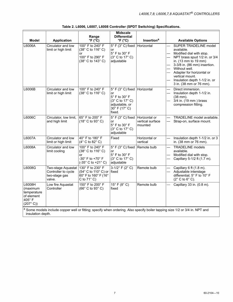
Table 2. L6006, L6007, L6008 Controller (SPDT Switching) Specifications.
Model ApplicationRange °F (°C)
Midscale Differential
°F (°C) Insertiona Available OptionsL6006A Circulator and low
limit or high limit100° F to 240° F (38° C to 116° C) or 100° F to 290° F(38° C to 143° C)
5° F (3° C) fixed or 5° F to 30° F (3° C to 17° C) adjustable
Horizontal � SUPER TRADELINE model available.
� Modified dial with stop.� NPT brass spud 1/2 in. or 3/4
in. (13 mm to 19 mm)� 3-3/8 in. (86 mm) insertion.� Without well.� Adapter for horizontal or
vertical mount.� Insulation depth 1-1/2 in. or
3 in. (38 mm or 76 mm).L6006B Circulator and low
limit or high limit100° F to 240° F (38° C to 116° C)
5° F (3° C) fixed or 5° F to 30° F (3° C to 17° C) adjustable, or 30° F (17° C) fixed.
Horizontal � Direct immersion.� Insulation depth 1-1/2 in.
(38 mm).� 3/4 in. (19 mm ) brass
compression fitting.
L6006C Circulator, low limit, and high limit
65° F to 200° F (18° C to 93° C)
5° F (3° C) fixed or 5° F to 30° F (3° C to 17° C) adjustable
Horizontal or vertical surface mounted
� TRADELINE model available.� Strap-on, surface mount.
L6007A Circulator and low limit or high limit
40° F to 180° F (4° C to 82° C)
Fixed Horizontal or vertical
� Insulation depth 1-1/2 in. or 3 in. (38 mm or 76 mm).
L6008A Circulator and low limit cooling
100° F to 240° F (38° C to 116° C) or -30° F to +70° F (-35° C to +21° C)
5° F (3° C) fixed or 5° F to 30° F (3° C to 17° C) adjustable
Remote bulb � TRADELINE models available.
� Modified dial with stop.� Capillary 5-1/2 ft (1.7 m).
L6008G Two-stage Aquastat Controller to cycle two-stage gas valve.
130° F to 230° F (54° C to 110° C) or 60° F to 160° F (16° C to 71° C)
3-1/2° F (2° C) fixed
Remote bulb � Capillary 6 ft (1.8 m).� Adjustable interstage
differential; 5° F to 10° F (2° C to 6° C).
L6008H (maximum temperature of element 405° F (207° C))
Low fire Aquastat Controller
150° F to 200° F (66° C to 93° C)
15° F (8° C) fixed
Remote bulb � Capillary 33 in. (0.8 m).
a Some models include copper well or fitting; specify when ordering. Also specify boiler tapping size 1/2 or 3/4 in. NPT and insulation depth.

L4006,7,8; L6006,7,8 AQUASTAT® CONTROLLERS
60-2104�10 8
INSTALLATION
When Installing This Product�1. Read these instructions carefully. Failure to follow them
could damage the product or cause a hazardous condition.
2. Check the ratings given in the instructions and on the product to make sure the product is suitable for your application.
3. Installer must be a trained, experienced service technician.
4. After installation is complete, check product operation as provided in these instructions.
WARNINGExplosion Hazard.Can cause serious injury, death or property damage.This product is intended for use only in systems with a pressure relief valve.
WARNINGElectrical Shock Hazard.Can cause serious injury or death.Disconnect power supply before beginning installation to prevent electrical shock or equipment damage.
CAUTIONEquipment Damage Hazard.Use of incorrect device or improper installation can damage the system.1. Do not replace immersion-type Aquastat Controller
with strap-on Aquastat Controller.2. Do not secure draw nut so tightly that retainer clamp
can collapse tubing.
IMPORTANT1. Terminals on these Aquastat relays are approved for
copper wire only.2. Controller may be used with or without immersion
well. If used, well must snugly fit sensing bulb for best thermal response. Insert bulb until it rests against the bottom of the well. Use well of correct length and bend the tubing, if necessary, to provide enough force to hold the bulb against the bottom of the well. Avoid making a sharp bend in the tubing as it can produce a break in the tubing and cause loss of fill. This condition causes the High and Low Limit controls to be made continuously.
3. If well does not snugly fit on bulb, use the heat-conductive compound, included with Super Tradeline and Tradeline models, as follows: Fold the plastic bag of compound lengthwise and twist gently. Snip the end of the bag and insert into the well. Slowly pull out the bag while squeezing firmly to distribute compound evenly in the well. Insert the bulb into the well. Bend the tubing, if necessary, to provide force to hold the bulb against the bottom of the well and to hold the outer end of the bulb firmly in contact with the side of the well. Wipe off excess compound.
The manufacturer usually provides a tapping for insertion of the controller sensing element. This tapping is located at a point where typical water temperature can be measured. Depending on the model, the element is inserted in an immersion well, through a boiler fitting, or directly immersed.
Installation should be made by a qualified service technician. Follow the instructions furnished by the system manufacturer, if available. Otherwise, refer to appropriate procedure listed below.
Mounting Immersion Well and Direct Immersion Models (L4006A,B,C,E,G; L4007A,B; L6006A,B; L6007A)
Installing Immersion Well Models (L4006A,B,E,G; L4007A,B; L6006A; L6007A)On an existing installation, shut off the power and remove the old control. If the old immersion well appears suitable, and if the adapter clamp on the Aquastat Controller fits the old well spud, this well does not need to be replaced.
To replace the well:1. If the system is filled, drain the system to a point below
the boiler tapping.2. Remove the old well from the boiler tapping.3. Install the immersion well included with the controller. If
the boiler tapping is greater than 1/2 in. (13 mm), use a reduction fitting to adapt the boiler opening to the 1/2 in. (13 mm) threads that are standard with the well or fitting. Fittings with 3/4 in. (19 mm) threads are also available.
4. Fill the system. Make sure that the well is screwed in tightly enough to prevent leakage. Do not use the case as a handle to tighten the well after the controller is secured to the well.
To install the controller:1. Loosen the screw (at the top of the case, above the
scale setting), and remove the cover. Loosen the two screws that secure the adapter clamp. (See Fig. 6).
2. Insert the sensing element into the immersion well.3. Fasten the case of the Aquastat Controller to the well
with the adapter clamp. Make certain that the clamp is properly positioned over the groove of the well spud. Also, be sure the flange at the opening of the well fits snugly into the opening of the case. The sensing bulb must bottom in the well.
NOTE: Some models include up to 3 in. (76 mm) extra capil-lary tubing inside the case. In these models, pull out the extra tubing, if needed.

L4006,7,8; L6006,7,8 AQUASTAT® CONTROLLERS
9 60-2104�10
Fig. 6. Internal view of L6006A.
Installing Direct Immersion Models (L4006C, L6006B)Models that provide for direct immersion of the sensing element into the boiler include a bulb compression fitting assembly instead of an immersion well. Install the fitting in the boiler tapping as follows:
1. Be sure the sealing washer is in place as shown in Fig. 7. Make sure that the spud of the bulb compression fitting is screwed in tightly enough to prevent leaking.
Fig. 7. Direct immersion model with fitting partially removed.
2. Insert the immersion sensing bulb through the bulb compression fitting. Adjust the adapter clamp so that the clamp fits over the groove at the opening of the bulb compression fitting.
3. Tighten the adapter clamp screws so that the Aquastat Controller is firmly attached to the bulb compression fitting.
Mounting Remote Bulb Models (L4008A,B,E; L6008A,G,H)The remote temperature-sensing bulb can either be installed in an immersion well (See Fig. 8) that extends into the boiler or tank, or it can be directly immersed in the controlled medium (See Fig. 9). For installations that do not use a well, secure the remote bulb with a bulb compression fitting (See Fig. 10), or capillary compression fitting. (See Fig. 11).
Order well, well adapter, bulb compression fitting or capillary compression fitting separately. See form no. 68-0040, Wells and Fittings for Temperature Controllers. If used, well must snugly fit sensing bulb for the best thermal response. Insert bulb until it rests against the bottom of the well. Hold it there while tightening the tubing clamp. (See Fig. 8).
The boiler manufacturer usually provides a tapping for the insertion of the Aquastat Controller sensing element. This tapping should be located at a point where typical water temperature can be measured. Never locate the bulb or protecting immersion well close to a hot or cold water inlet or a steam coil.
If the system is filled, drain system to a point below the boiler tapping, or wherever the sensing bulb is to be installed.
The bulb can also be installed in the supply line of an indirect water heater, in the direct water heater itself, or in the feed riser, about 6 in. (153 mm) above the boiler. If the riser is valved, the bulb can be installed between the boiler and the valve.
NOTE: Do not make sharp bends or kinks in the capillary. Make bends no sharper than 1 in. (25 mm) radius.
After installing the controller, carefully coil the excess capillary at the bottom of the controller case.
Mounting Immersion Well 1. Screw the well into the boiler, tank, or pipe tapping.2. Insert the bulb in the well, pushing the tubing until the
bulb bottoms in the well.3. Attach the retainer clamp to the end of the well spud.
Loosen the draw nut and spread the jaws of the clamp with the screwdriver if necessary. (See Fig. 8).
4. With the retainer clamp attached to the well spud (be sure the jaws of the clamp hook over the ridge at the end of the spud, as shown at points A in Fig. 8), adjust the tubing to fit through the retainer clamp groove, as shown at point B in Fig. 8.
5. Tighten the draw nut so that the retainer clamp is firmly attached to the well spud and the tubing is held securely in place.
M8806A
SETPOINTINDICATING DIAL
DIFFERENTIALADJUSTMENTWHEEL
ADAPTER CLAMPSCREWS
INSERTIONELEMENT
WITH VERTICAL MOUNTING OFIMMERSION WELL, ELEMENT IS ATTACHED TO BOTTOM OF THE CASE.
SELECT MODELS HAVE SCREW TERMINAL, NOT TAB TERMINAL.
1
2
2
1
M8774ASENSING BULB
BULB COMPRESSIONFITTING
SEALING WASHER
ADAPTER CLAMPSFIT OVER GROOVE
SPLIT SLEEVE
ADAPTER CLAMP

L4006,7,8; L6006,7,8 AQUASTAT® CONTROLLERS
60-2104�10 10
Fig. 8. Immersion well fitting.
Fig. 9. Internal view of L4008L or L6008G.
Mounting With Bulb Compression Fitting1. Screw the fitting into the boiler or pipe tapping.2. Slide the sealing washer onto the bulb.3. Insert the bulb into the fitting until the bulb bottoms.4. Slide the split sleeve into the fitting. (See Fig. 10).
Fig. 10. Bulb compression fitting.Use with L4006A,B; L6008A.
5. Place clamps A and B on the assembly so that the sleeve is drawn into the fitting when the screws are tightened.
NOTE: Make sure that the nub on clamp A engages the space between the sleeve and the clamp.
6. Tighten the clamp screws evenly.
Mounting With Capillary Compression Fitting1. Screw the fitting into the boiler or pipe tapping.2. Place the packing nut on the tubing.3. Slide the bulb completely through the fitting.4. Place the composition disk and four slotted brass
washers on the tubing in the order shown in Fig. 11. Turn the brass washers so the slots are 180 degrees apart.
Fig. 11. Capillary compression fitting. Use with L4008.
5. Slide the seal assembly into the fitting and tighten the packing nut.
Duct Mounting1. Drill a 3/4 in. (19 mm) hole in the duct wall large enough
to admit the sensing bulb into the holder.2. Using the holder as a template, mark and drill holes for
the bulb holder mounting screws. (See Fig. 12).
M8777A
WELLBULB
SPUDMOUNTINGCLAMP
A
DRAW NUT
TUBING
B
MOUNTING CLAMP
SCREWDRIVER
SPREAD JAWSTO FIT OVERRIDGE ON WELL SPUD
JAWS
220
240
100
120140
160
180
200
MOUNTING HOLES (3)
RIGHT SNAPSWITCH (NO. 1)
LEFT SNAP SWITCH(NO. 2)
NOTCHES FOR CAPILLARY TUBE (4)
7/8 IN. (22 MM) DIAMETERKNOCKOUT BOTH ENDS
27-1/2 IN. (70 MM)SENSOR
10 FT. (3.0 M)CAPILLARY TUBE
M4673A
1
1 SELECT MODELS HAVE SIX TERMINALS.
M8815A
CLAMP B
CLAMP ACLAMP SCREWS (2)
BULB COMPRESSION FITTING SEALING
WASHER
BULB
INSERTION LENGTHAPPROX. 3-3/16 IN. (81 MM)
SPLIT SLEEVE
COMPOSITION DISK(SLOTTED)
BOILER PLUG
CAPILLARY TUBING
EXAMPLE OF SLOTTED WASHERS ASSEMBLED IN PAIRS:PACKING NUT M8816A
IMMERSIONBULB

L4006,7,8; L6006,7,8 AQUASTAT® CONTROLLERS
11 60-2104�10
Fig. 12. Bulb support.
3. Break the holder to the desired length. (See Fig. 13).
NOTE: The holder must be long enough to hold the sensing bulb in freely circulating air away from the duct wall. Neatly coil the excess capillary at the controller case or at the bulb holder.
Fig. 13. Removing excess bulb support.
Fig. 14. Securing capillary in bulb holder.
4. Place the capillary in the bulb holder channel. Pinch the top edges of the holder together at each segment. (See Fig. 14).
5. Insert the bulb holder into the controlled area through the hole prepared in step 1.
6. Fasten the bulb holder to the duct wall with the screws provided.
Mounting Remote Bulb Models For Outdoor Air SensingThese models have a 5 ft (1.5 m) capillary that establishes the maximum distance between the case and the outdoor mounting.
Install the bulb on the outside of the building in the shield provided (See Fig. 15) where it can be exposed to representative air temperature, but not to direct sunlight. Mount the bulb high enough so that accumulated snow, leaves, or other debris cannot obstruct circulation of air around it, and where children cannot reach it. Avoid vents from the building.
Install the case at the indoor location selected, fastening the screws through holes in the back of the case. Bring out the bulb and tubing through a 3/4 in. (19 mm) hole in the outside wall, avoiding sharp bends or kinks. Leave excess tubing coiled near the case. Do not make sharp bends near the case or bulb.
Slip the bulb through the supports in the shield. Pinch the split supporting clip until it holds the bulb firmly in position. If the seal-off tube protrudes from under the shield, bend it under as shown in Fig. 15.
Hold the shield over the mounting position and form a small-radius bend in the tubing. Place the split plug around the tubing and move the shield into the mounting location as a unit. Push the split plug into the hole until it is wedged securely in place. Fasten the shield in place on the wall with the screws provided.
NOTE: If the tubing is properly shaped and the split plug installed as directed, the shield will cover the split plug, and the hole in the wall will be hidden from sight.
Fig. 15. Mounting bulb in shield outside building.
Mounting L6008A Remote Bulb Controller
Mounting with Guard BracketMount the bulb in the guard bracket as shown in Fig. 16. Locate the bulb and bracket combination, in freely circulating air, in the controlled area. With screws provided, fasten the bracket in place.
M8970A
M7216A
PINCH TOP EDGES OFHOLDER TOGETHERAT EACH SEGMENT
CAPILLARYTUBING
SENSINGBULB
BE SURE EXTENSION TUBE IS UNDER BULB HOLDER, AS SHOWN M7217A
M8800A
INSERT BULBIN CLAMP
OUTDOORSENSINGBULB
SEAL-OFFTUBE
34886ABULBSHIELD
CAPILLARYTUBING
SPLIT WOOD PLUG
3/4 IN. (19 MM)HOLE IN WALL

L4006,7,8; L6006,7,8 AQUASTAT® CONTROLLERS
60-2104�10 12
Mounting on Suction Line1. In cooling units with more than one suction line, place
the sensing bulb on the common line.2. Make certain the bulb is at least 2 ft (0.6 m) from the
point at which the suction line leaves the cooler. This prevents the outside temperature from being transmitted to the remote bulb through the copper tubing of the suction line.
3. Place the remote sensing bulb on the side of the horizontal suction line between the coil and trap (not on the trap).
4. Attach the sensing bulb to the suction line with clips or straps. (See Fig. 17).
5. Coil the excess length of capillary tubing near the L6008A case.
Fig. 16. Securing remote bulb in clipwhen mounting with guard bracket.
Fig. 17. Attaching remote bulb to horizontal suction line.
Mounting Surface Mount ModelsThe L4006H and L6006C are designed for surface mounting on piping or tanks. Mount the controller directly on the tank surface using the adjustable mounting bracket as shown in Fig. 18. The controller can be mounted in any position.
When mounting the L4006H or L6006C on piping, the pipe should be 1 in. (25 mm) diameter or larger for accurate temperature sensing. Remove any insulation from the pipe. Thoroughly scrape off all scale, rust, or paint. Mount the controller using adjustable bracket provided. Turn on power.
WiringDisconnect power supply before beginning installation to prevent electrical shock or equipment damage.
All wiring must comply with local codes and ordinances regarding wire size, type of insulation, enclosure, etc.
Figures 19 through 28 show typical hookups.
When wiring a switch equipped with a 1/4 in. (19 mm) tab terminal connector, use 18 AWG to 22 AWG (0.8 mm2 to 0.3 mm2) gauge wire with an AMP Inc. part no. 2-520129-2 fully insulated flag receptable connector or equivalent.
Fig. 18. Mounting L4006H or L6006C directly on surface.
Fig. 19. Typical gas-fired system with domestic hot water.
M8791A
SUPPORTING CLIP
SENSOR
M8805A
L6008ACIRCULATORLOW LIMITCONTROLLER
CAPILLARY REMOTE BULB
SUCTIONLINE
BULB CLIPSTO SUCTION LINE
COIL
COOLERWALL
SUCTION LINELEAVES COOLER
M8771B
ENCLOSEDSENSING BULB
PIPE
12 IN.ADJUSTABLEPIPE STRAP
AQUASTATCONTROLLER CASE
MOUNTINGBRACKET
®
POWER SUPPLY. PROVIDE DISCONNECT MEANS ANDOVERLOAD PROTECTION AS REQUIRED.
USE L4006E FOR MANUAL RESET.
1
2 M2856B
2
L1 (HOT)L2
1
24 VOLTTHERMOSTAT
LOW WATERCUTOFF
PRESSURE CONTROL
L4006A ORL4007ALOW LIMITAQUASTATCONTROLLER
GASVALVE
PILOTSTATCONTROL®

L4006,7,8; L6006,7,8 AQUASTAT® CONTROLLERS
13 60-2104�10
Fig. 20. Typical oil-fired gravity system.
Fig. 21. L6008A used to control cooling equipment and indicating light.
Fig. 22. Typical oil-fired hydronic system with domestic hot water.
Fig. 23. Typical oil-fired hydronic heating system that provides year-round domestic hot water using RA832A.
Fig. 24. Typical connection diagram for an oil-fired, hydronic heating system that provides year-round
domestic hot water using RA817A.
L1 (HOT)
L2
1
1 POWER SUPPLY. PROVIDE DISCONNECT MEANS AND OVERLOAD PROTECTION AS REQUIRED.
PROTECTORELAYCONTROL
L4006A OR L4007A HIGH LIMIT CONTROLLER
IGNITION24 VOLTTHERMOSTAT
BURNERMOTOR
OIL VALVE(IF USED)
M1054B
1
2
3
4
T
T
L1 (HOT)
L2
1
1 POWER SUPPLY. PROVIDE DISCONNECT MEANS AND OVERLOAD PROTECTION AS REQUIRED.
L6008ACIRCULATOR ANDLOW LIMIT CONTROLLER
R
W
B
M8780A
COOLINGEQUIPMENT
INDICATINGLIGHT
L1 (HOT)
L2
1
3 4
2
1
2
3
4
POWER SUPPLY. PROVIDE DISCONNECT MEANS AND OVERLOAD PROTECTION AS REQUIRED.
L6006C USED AS HIGH LIMIT CONTROL.
L6006C USED AS AN OPERATING CONTROL.
R-B OPENS, R-W CLOSES ON TEMPERATURE RISE. M8960B
PROTECTORELAYCONTROL HIGH LIMIT
CONTROLLER
CIRCULATORAND LOWLIMIT CONTROL
W
R
B
1
2
4
3
T
T
IGNITION
BURNERMOTOR
24VTHERMOSTAT
SWITCHING RELAY
CIRCULATOR
LINE VOLTAGELOW VOLTAGE
1
2
3
4
T
T
IGNITION
BURNER
L4006B OR L4007BCIRCULATORAQUASTATCONTROLLER
CIRCULATOR
L4006A OR L4007A LOW LIMITAQUASTAT CONTROLLER
L1(HOT)
L2L4006A OR L4007AHIGH LIMITAQUASTATCONTROLLER
24 VOLTTHERMOSTAT
RA832ASWITCHING RELAY
PROTECTORELAYCONTROL
POWER SUPPLY. PROVIDE DISCONNECT MEANS ANDOVERLOAD PROTECTION AS REQUIRED.
USE L4006E FOR MANUAL RESET.
1
2 M2855B
T T
X X 4
2
1
1
2
®
®
®
L1 (HOT)
L21
1
2
POWER SUPPLY. PROVIDE DISCONNECT MEANS AND OVERLOAD PROTECTION AS REQUIRED.
SELECT MODELS HAVE 1/4 IN. (6) TAB TERMINAL FOR W TERMINAL.
L4008A OR EHIGH LIMIT CONTROLLER
L6008A CIRCULATORLOW LIMIT CONTROLLER
RW BCIRCULATOR IGNITIONTRANSFORMER
RA89A RELAY
RA817APROTECTORELAYCONTROL
BURNER MOTOR24V THERMOSTAT
2 1 3 4
T T
1
2
3
4
M8785B
2
L4006,7,8; L6006,7,8 AQUASTAT® CONTROLLERS
60-2104�10 14
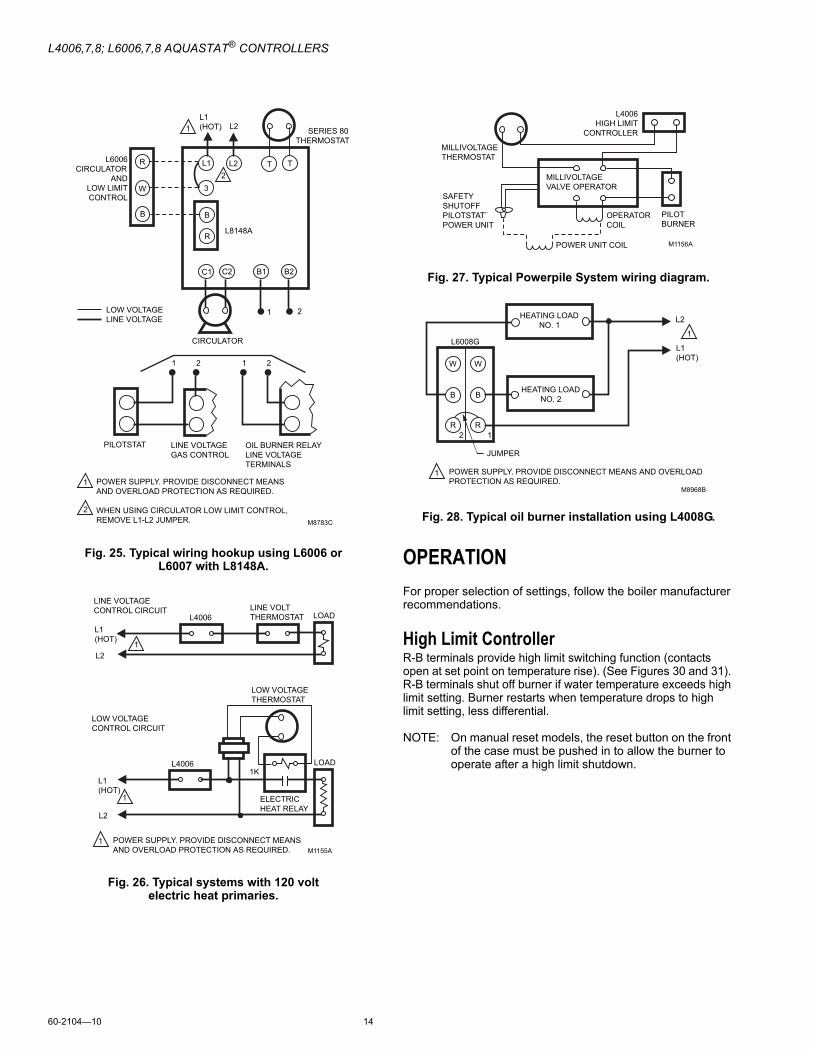
Fig. 25. Typical wiring hookup using L6006 orL6007 with L8148A.
Fig. 26. Typical systems with 120 voltelectric heat primaries.
Fig. 27. Typical Powerpile System wiring diagram.
Fig. 28. Typical oil burner installation using L4008G.
OPERATIONFor proper selection of settings, follow the boiler manufacturer recommendations.
High Limit ControllerR-B terminals provide high limit switching function (contacts open at set point on temperature rise). (See Figures 30 and 31). R-B terminals shut off burner if water temperature exceeds high limit setting. Burner restarts when temperature drops to high limit setting, less differential.
NOTE: On manual reset models, the reset button on the front of the case must be pushed in to allow the burner to operate after a high limit shutdown.
L1 (HOT) L21
1
2
POWER SUPPLY. PROVIDE DISCONNECT MEANS AND OVERLOAD PROTECTION AS REQUIRED.
WHEN USING CIRCULATOR LOW LIMIT CONTROL, REMOVE L1-L2 JUMPER.
2
L6006CIRCULATOR
ANDLOW LIMITCONTROL
L1 L2
3
T TR
W
B B
R
C1 C2 B1 B2
SERIES 80 THERMOSTAT
L8148A
CIRCULATOR
PILOTSTAT LINE VOLTAGEGAS CONTROL
OIL BURNER RELAYLINE VOLTAGETERMINALS
1
1
2
21 2
M8783C
LOW VOLTAGELINE VOLTAGE
L1 (HOT)
L21
L1 (HOT)
L2
1
1 POWER SUPPLY. PROVIDE DISCONNECT MEANS AND OVERLOAD PROTECTION AS REQUIRED.
LINE VOLTAGECONTROL CIRCUIT
L4006LINE VOLTTHERMOSTAT LOAD
LOW VOLTAGECONTROL CIRCUIT
L4006
LOW VOLTAGETHERMOSTAT
1K
ELECTRICHEAT RELAY
LOAD
M1155A
MILLIVOLTAGETHERMOSTAT
L4006HIGH LIMIT
CONTROLLER
MILLIVOLTAGEVALVE OPERATOR
SAFETYSHUTOFFPILOTSTAT¨POWER UNIT
POWER UNIT COIL
OPERATORCOIL
PILOTBURNER
M1156A
L1 (HOT)
L2
1
1 POWER SUPPLY. PROVIDE DISCONNECT MEANS AND OVERLOAD PROTECTION AS REQUIRED.
JUMPER
M8968B
HEATING LOADNO. 2
HEATING LOADNO. 1
R R
B B
W W
2 1
L6008G
L4006,7,8; L6006,7,8 AQUASTAT® CONTROLLERS
15 60-2104�10
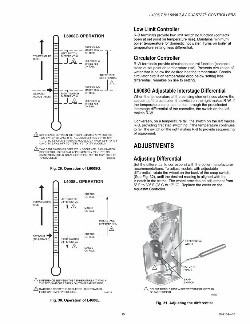
Fig. 29. Operation of L6008G.
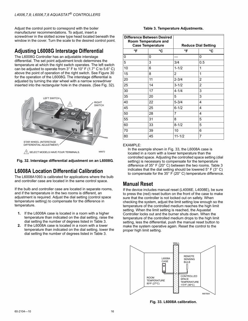
Fig. 30. Operation of L4008L.
Low Limit ControllerR-B terminals provide low limit switching function (contacts open at set point on temperature rise). Maintains minimum boiler temperature for domestic hot water. Turns on boiler at temperature setting, less differential.
Circulator ControllerR-W terminals provide circulation control function (contacts close at set point on temperature rise). Prevents circulation of water that is below the desired heating temperature. Breaks circulator circuit on temperature drop below setting less differential; remakes on rise to setting.
L6008G Adjustable Interstage DifferentialWhen the temperature at the sensing element rises above the set point of the controller, the switch on the right makes R-W. If the temperature continues to rise through the preselected interstage differential of the controller, the switch on the left makes R-W.
Conversely, on a temperature fall, the switch on the left makes R-B, providing first step switching. If the temperature continues to fall, the switch on the right makes R-B to provide sequencing of equipment.
ADJUSTMENTS
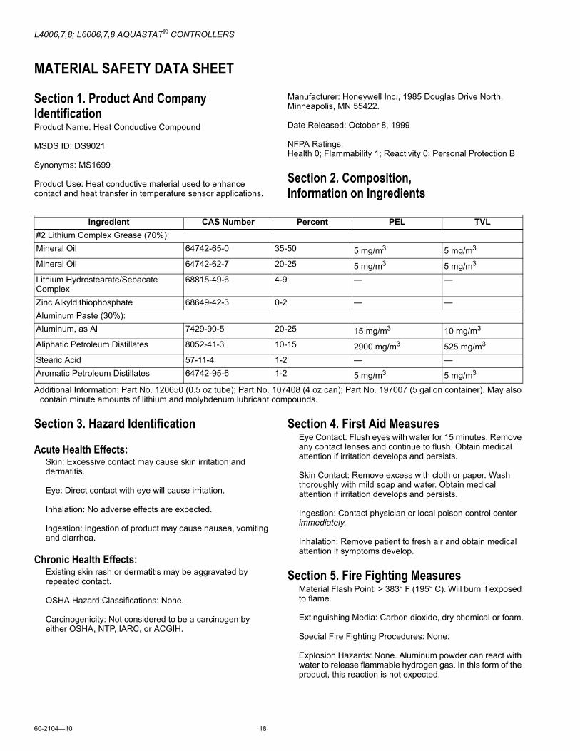
Adjusting DifferentialSet the differential to correspond with the boiler manufacturer recommendations. To adjust models with adjustable differential, rotate the wheel on the back of the snap switch, (See Fig. 32), until the desired reading is aligned with the V notch in the frame. The wheel provides an adjustment from 5° F to 30° F (3° C to 17° C). Replace the cover on the Aquastat Controller.
Fig. 31. Adjusting the differential.
TEMPERATURERISE
SETPOINT(ADJUSTABLE)
LEFT SWITCHDIFFERENTIAL
RIGHT SWITCHDIFFERENTIAL
BREAKS R-BMAKES R-WON RISE
BREAKS R-BMAKES R-WON RISE
BREAKS R-WMAKES R-BON FALL
BREAKS R-WMAKES R-BON FALL
INTERSTAGE DIFFERENTIAL
DIFFERENCE BETWEEN THE TEMPERATURES AT WHICH THE TWO SWITCHES MAKE R-W. ADJUSTABLE FROM 3°F TO 10°F (1.7°C TO 5.6°C) ON STANDARD MODELS, OR FROM 3.6°F TO 12°F (2.0°C TO 6.7°C); 55°F TO 175°F (13°C TO 79°C) MODELS.
TWO SPDT SWITCHES OPERATE IN SEQUENCE. EACH SWITCHDIFFERENTIAL IS FIXED AT APPROXIMATELY 3°F (1.7°C) ONSTANDARD MODELS, OR AT 3.6°F (2.0°C); 55°F TO 175°F (13°C TO79°C) MODELS.
1
2
1
2
2
M2999B
TEMPERATURERISE
SETPOINT(ADJUSTABLE)
LEFT SWITCHDIFFERENTIAL
RIGHT SWITCHDIFFERENTIAL
BREAKSON RISE
BREAKSON RISE
MAKESON FALL
MAKESON FALL
INTERSTAGE DIFFERENTIAL
DIFFERENCE BETWEEN THE TEMPERATURES AT WHICH THE TWO SWITCHES BREAK ON TEMPERATURE RISE.
SWITCHES OPERATE IN SEQUENCE. RIGHT SWITCH FIRST-ON TEMPERATURE RISE.
1
2
1
2
2
M4671AM8969
DIFFERENTIALWHEEL
NOTCH INFRAME
SNAPSWITCH
SELECT MODELS HAVE A SCREW TERMINAL INSTEAD OF TAB TERMINAL.
1
1
L4006,7,8; L6006,7,8 AQUASTAT® CONTROLLERS
60-2104�10 16
Adjust the control point to correspond with the boiler manufacturer recommendations. To adjust, insert a screwdriver in the slotted screw type head located beneath the window in the cover. Turn the scale to the desired control point.
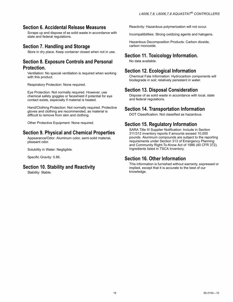
Adjusting L6008G Interstage DifferentialThe L6008G Controller has an adjustable interstage differential. The set point adjustment knob determines the temperature at which the right switch operates. The left switch can be adjusted to operate from 3° F to 10° F (1.7° C to 5.6° C) above the point of operation of the right switch. See Figure 30 for the operation of the L6008G. The interstage differential is adjusted by turning the star wheel with a narrow screwdriver inserted into the rectangular hole in the chassis. (See Fig. 32).
Fig. 32. Interstage differential adjustment on an L6008G.
L6008A Location Differential CalibrationThe L6008A1093 is calibrated for applications where the bulb and controller case are located in the same control space.
If the bulb and controller case are located in separate rooms, and if the temperature in the two rooms is different, an adjustment is required. Adjust the dial setting (control space temperature setting) to compensate for the difference in temperature.
1. If the L6008A case is located in a room with a higher temperature than indicated on the dial setting, raise the dial setting the number of degrees listed in Table 3.
2. If the L6008A case is located in a room with a lower temperature than indicated on the dial setting, lower the dial setting the number of degrees listed in Table 3.
Table 3. Temperature Adjustments.
EXAMPLE:In the example shown in Fig. 33, the L6008A case is located in a room with a lower temperature than the controlled space. Adjusting the controlled space setting (dial setting) is necessary to compensate for the temperature difference of 35° F (20° C) between the two rooms. Table 3 indicates that the dial setting should be lowered 5° F (3° C) to compensate for the 35° F (20° C) temperature difference.
Manual ResetIf the device includes manual reset (L4006E, L4008E), be sure to press the (red) reset button on the front of the case to make sure that the controller is not locked out on safety. When checking the system, adjust the limit setting low enough so the temperature of the controlled medium reaches the high limit setting. When the limit setting is reached, the Aquastat Controller locks out and the burner shuts down. When the temperature of the controlled medium drops to the high limit setting, less the differential, push the manual reset button to make the system operative again. Reset the control to the proper high limit setting.
Fig. 33. L6008A calibration.
M8972
RIGHTSWITCH
LEFT SWITCH
STAR WHEEL (INTERSTAGEDIFFERENTIAL ADJUSTMENT)
1
1
SELECT MODELS HAVE FOUR TERMINALS.
Difference Between Desired Room Temperature and
Case Temperature Reduce Dial Setting°F °C °F °C
0 0 � 05 3 3/4 0.510 6 1-1/2 115 8 2 120 11 2-3/4 225 14 3-1/2 230 17 4-1/4 335 20 5 340 22 5-3/4 445 25 6-1/2 450 28 7 455 31 8 560 33 8-1/2 570 39 10 680 45 11-1/2 7
M8790A
WALL
L6008ACASE
REMOTESENSING BULB
CONTROLLEDSPACETEMPERATURE115oF (46oC)
ROOM TEMPERATURE80oF (27oC)

L4006,7,8; L6006,7,8 AQUASTAT® CONTROLLERS
17 60-2104�10
CHECKOUT
WARNINGExplosion Hazard.Can cause serious injury, death or property damage.This product is intended for use only in systems with a pressure relief valve.
Check to make certain that the Aquastat Controller is properly installed and adjusted. Put the system into operation and observe the action of the controller through several cycles to make certain it provides proper control of the system as described in the OPERATION section. Make any additional adjustments necessary for assuring comfort requirements.
L4006,7,8; L6006,7,8 AQUASTAT® CONTROLLERS
60-2104�10 18
MATERIAL SAFETY DATA SHEET
Section 1. Product And Company IdentificationProduct Name: Heat Conductive Compound
MSDS ID: DS9021
Synonyms: MS1699
Product Use: Heat conductive material used to enhance contact and heat transfer in temperature sensor applications.
Manufacturer: Honeywell Inc., 1985 Douglas Drive North, Minneapolis, MN 55422.
Date Released: October 8, 1999
NFPA Ratings:Health 0; Flammability 1; Reactivity 0; Personal Protection B
Section 2. Composition, Information on Ingredients
Additional Information: Part No. 120650 (0.5 oz tube); Part No. 107408 (4 oz can); Part No. 197007 (5 gallon container). May also contain minute amounts of lithium and molybdenum lubricant compounds.
Section 3. Hazard Identification
Acute Health Effects:Skin: Excessive contact may cause skin irritation and dermatitis.
Eye: Direct contact with eye will cause irritation.
Inhalation: No adverse effects are expected.
Ingestion: Ingestion of product may cause nausea, vomiting and diarrhea.
Chronic Health Effects:Existing skin rash or dermatitis may be aggravated by repeated contact.
OSHA Hazard Classifications: None.
Carcinogenicity: Not considered to be a carcinogen by either OSHA, NTP, IARC, or ACGIH.
Section 4. First Aid MeasuresEye Contact: Flush eyes with water for 15 minutes. Remove any contact lenses and continue to flush. Obtain medical attention if irritation develops and persists.
Skin Contact: Remove excess with cloth or paper. Wash thoroughly with mild soap and water. Obtain medical attention if irritation develops and persists.
Ingestion: Contact physician or local poison control center immediately.
Inhalation: Remove patient to fresh air and obtain medical attention if symptoms develop.
Section 5. Fire Fighting MeasuresMaterial Flash Point: > 383° F (195° C). Will burn if exposed to flame.
Extinguishing Media: Carbon dioxide, dry chemical or foam.
Special Fire Fighting Procedures: None.
Explosion Hazards: None. Aluminum powder can react with water to release flammable hydrogen gas. In this form of the product, this reaction is not expected.
Ingredient CAS Number Percent PEL TVL#2 Lithium Complex Grease (70%):Mineral Oil 64742-65-0 35-50 5 mg/m3 5 mg/m3
Mineral Oil 64742-62-7 20-25 5 mg/m3 5 mg/m3
Lithium Hydrostearate/Sebacate Complex
68815-49-6 4-9 � �
Zinc Alkyldithiophosphate 68649-42-3 0-2 � �Aluminum Paste (30%):Aluminum, as Al 7429-90-5 20-25 15 mg/m3 10 mg/m3
Aliphatic Petroleum Distillates 8052-41-3 10-15 2900 mg/m3 525 mg/m3
Stearic Acid 57-11-4 1-2 � �Aromatic Petroleum Distillates 64742-95-6 1-2 5 mg/m3 5 mg/m3
L4006,7,8; L6006,7,8 AQUASTAT® CONTROLLERS
19 60-2104�10
Section 6. Accidental Release MeasuresScrape up and dispose of as solid waste in accordance with state and federal regulations.
Section 7. Handling and StorageStore in dry place. Keep container closed when not in use.
Section 8. Exposure Controls and Personal Protection.
Ventilation: No special ventilation is required when working with this product.
Respiratory Protection: None required.
Eye Protection: Not normally required. However, use chemical safety goggles or faceshield if potential for eye contact exists, especially if material is heated.
Hand/Clothing Protection: Not normally required. Protective gloves and clothing are recommended, as material is difficult to remove from skin and clothing.
Other Protective Equipment: None required.
Section 9. Physical and Chemical PropertiesAppearance/Odor: Aluminum color, semi-solid material, pleasant odor.
Solubility in Water: Negligible.
Specific Gravity: 0.86.
Section 10. Stability and ReactivityStability: Stable.
Reactivity: Hazardous polymerization will not occur.
Incompatibilities: Strong oxidizing agents and halogens.
Hazardous Decomposition Products: Carbon dioxide, carbon monoxide.
Section 11. Toxicology Information.No data available.
Section 12. Ecological InformationChemical Fate Information: Hydrocarbon components will biodegrade in soil; relatively persistent in water.
Section 13. Disposal ConsiderationDispose of as solid waste in accordance with local, state and federal regulations.
Section 14. Transportation InformationDOT Classification: Not classified as hazardous.
Section 15. Regulatory InformationSARA Title III Supplier Notification: Include in Section 311/312 inventory reports if amounts exceed 10,000 pounds. Aluminum compounds are subject to the reporting requirements under Section 313 of Emergency Planning and Community Right-To-Know Act of 1986 (40 CFR 372). Ingredients listed in TSCA Inventory.
Section 16. Other InformationThis information is furnished without warranty, expressed or implied, except that it is accurate to the best of our knowledge.

Automation and Control SolutionsHoneywell International Inc. Honeywell Limited-Honeywell Limitée1985 Douglas Drive North 35 Dynamic DriveGolden Valley, MN 55422 Toronto, Ontario M1V 4Z9customer.honeywell.com
L4006,7,8; L6006,7,8 AQUASTAT® CONTROLLERS
® U.S. Registered Trademark© 2006 Honeywell International Inc.60-2104�10 J.I. Rev. 12-06
Ther
mom
eter
s
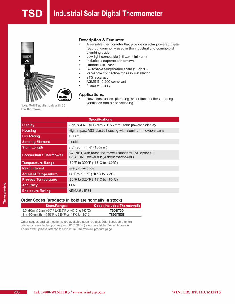
TSD Industrial Solar Digital Thermometer
208 Tel: 1-800-WINTERS / www.winters.com WINTERS INSTRUMENTS
Description & Features:• Aversatilethermometerthatprovidesasolarpowereddigital readoutcommonlyusedintheindustrialandcommercial plumbingtrade• Lowlightcompatible(16Luxminimum)• Includesaseparablethermowell• DurableABScase• Switchabletemperaturescale(°For°C)• Vari-angleconnectionforeasyinstallation• ±1%accuracy• ASMEB40.200compliant• 5yearwarranty
Applications:• Newconstruction,plumbing,waterlines,boilers,heating, ventilationandairconditioning
SpecificationsDisplay 2.55”x4.67”(63.7mmx116.7mm)solarpowereddisplayHousing HighimpactABSplastichousingwithaluminummovablepartsLux Rating 16LuxSensing Element LiquidStem Length 3.5”(90mm),6”(150mm)
Connection / Thermowell 3/4”NPT,withbrassthermowellstandard,(SSoptional)1-1/4”UNFswivelnut(withoutthermowell)
Temperature Range -50°Fto320°F(-45°Cto160°C)Read Interval Every6secondsAmbient Temperature 14°Fto150°F(-10°Cto65°C)Process Temperature -50°Fto320°F(-45°Cto160°C)Accuracy ±1%Enclosure Rating NEMA5/IP54
Note:RoHSappliesonlywithSSTIWthermowell
Order Codes (products in bold are normally in stock)Stem/Ranges Code (Includes Thermowell)
3.5” (90mm) Stem (-50°F to 320°F or -45°C to 160°C) TSD9ITSD6” (150mm) Stem (-50°F to 320°F or -45°C to 160°C) TSD9ITSD6
Otherrangesandconnectionsizesavailableuponrequest.Ductflangeandunionconnectionavailableuponrequest.6”(150mm)stemavailable.ForanIndustrialThermowell,pleaserefertotheIndustrialThermowellproductpage.
Thermom
eters
209WINTERS INSTRUMENTS Tel: 1-800-WINTERS / www.winters.com
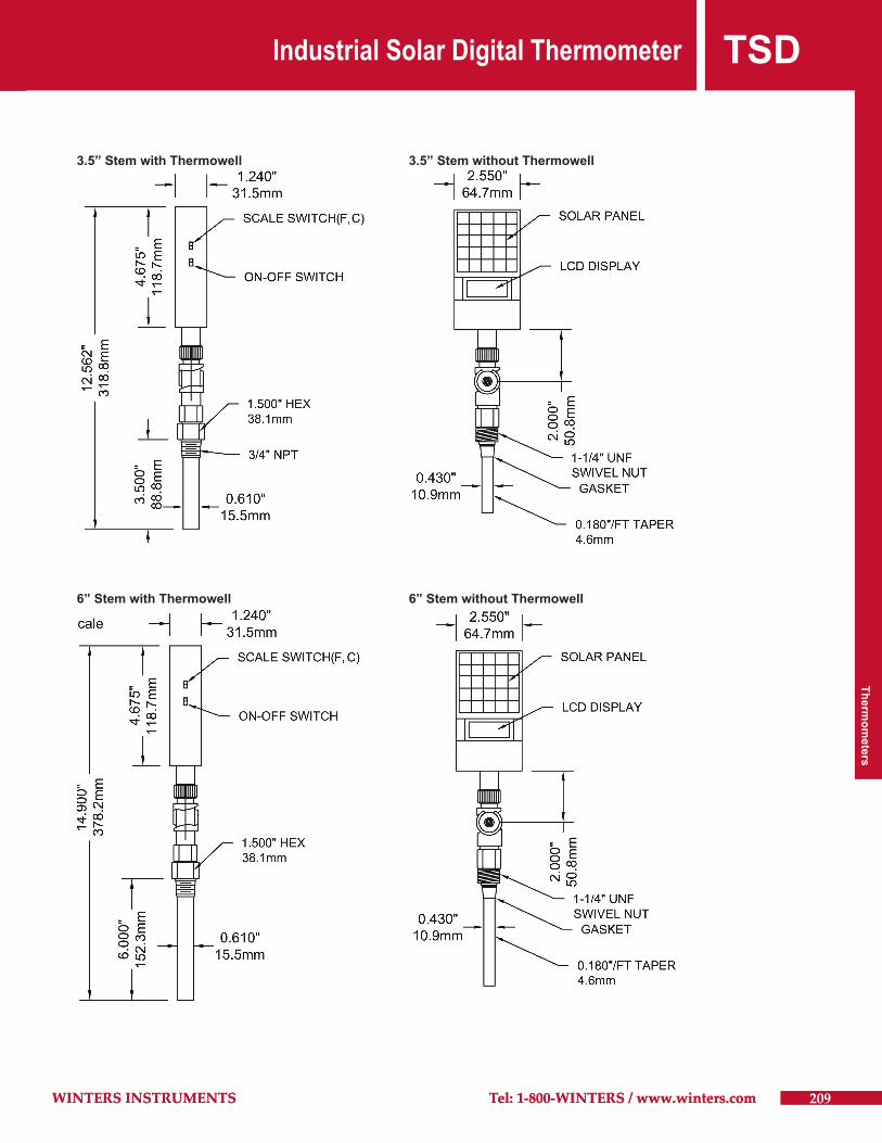
TSDIndustrial Solar Digital Thermometer
209WINTERS INSTRUMENTS Tel: 1-800-WINTERS / www.winters.com
3.5” Stem with Thermowell 3.5” Stem without Thermowell
6” Stem with Thermowell 6” Stem without Thermowell