spe 66343 parallel computing techniques for large-scale reservoir...
TRANSCRIPT
Copyright 2001, Society of Petroleum Engineers Inc.
This paper was prepared for presentation at the SPE Reservoir Simulation Symposium held inHouston, Texas, 11–14 February 2001.
This paper was selected for presentation by an SPE Program Committee following review ofinformation contained in an abstract submitted by the author(s). Contents of the paper, aspresented, have not been reviewed by the Society of Petroleum Engineers and are subject tocorrection by the author(s). The material, as presented, does not necessarily reflect anyposition of the Society of Petroleum Engineers, its officers, or members. Papers presented atSPE meetings are subject to publication review by Editorial Committees of the Society ofPetroleum Engineers. Electronic reproduction, distribution, or storage of any part of this paperfor commercial purposes without the written consent of the Society of Petroleum Engineers isprohibited. Permission to reproduce in print is restricted to an abstract of not more than 300words; illustrations may not be copied. The abstract must contain conspicuousacknowledgment of where and by whom the paper was presented. Write Librarian, SPE, P.O.Box 833836, Richardson, TX 75083-3836, U.S.A., fax 01-972-952-9435.
AbstractMassively parallel computing techniques can overcomelimitations of problem size and space resolution for reservoirsimulation on single-processor machine. This paper reports onour work to parallelize a widely used numerical simulator,known as TOUGH2, for nonisothermal flows of multi-component, multiphase fluids in three-dimensional porous andfractured media. We have implemented the TOUGH2 packageon a Cray T3E-900, a distributed-memory massively parallelcomputer with 695 processors. For the simulation of large-scale multicomponent, multiphase fluid flow, the requirementsfor computer memory and computing time are extensive.Because of the limitation of computer memory in each PE(processing element), we distribute not only computing timebut also the memory requirement to different PEs. In thisstudy, the METIS software package for partitioningunstructured graph and meshes is adopted for domainpartitioning, and the Aztec linear solver package is used forsolving linear equation systems. The efficiency of the code isinvestigated through the modeling of a three-dimensionalvariably saturated flow problem, which involves more thanone million gridblocks. The execution time and speedup areevaluated through comparing the performance of differentnumbers of processors. The results indicate that the parallelcode can significantly improve capacity and efficiency forlarge-scale simulations.
IntroductionTOUGH21, 2 is a general-purpose numerical simulationprogram for multi-dimensional, multiphase, multicomponentheat and fluid flows in porous and fractured media. The codeis written in standard ANSI FORTRAN 77. Since its release in
1991, the program has been used worldwide in geothermalreservoir engineering, nuclear waste isolation, environmentalassessment and remediation, and modeling flow and transportin variably saturated media. The numerical scheme of theTOUGH2 code is based on the integral finite difference (IFD)method. The conservation equations involving mass of air,water, chemical components and thermal energy arediscretized in space using the IFD method. Time is discretizedfully implicitly using a first-order backward finite differencescheme. The discretized nonlinear system of finite differenceequations for mass and energy balances are solvedsimultaneously using the Newton/Raphson iterative scheme.For the basic version (i.e., single CPU), the code is equippedwith both direct and iterative solvers.3
The development of parallel computers has made itpossible to conduct large-scale reservoir simulations. In thepast decade, the total number of gridblocks used in a typicalreservoir simulation increased from thousands to millions.4
One of the most popular parallel computer architectures is thedistributed-memory machine, the massively parallel processor(MPP) computer, which can be made up of hundreds tothousands of processors. Elmroth et al.5 developed a parallelprototype scheme for the TOUGH2 code and implemented thecomputing time distribution on MPP computer. Theirinvestigation indicates that a parallel code can dramaticallyenhance computational efficiency.
The present work presents the further progress in reducingmemory requirement and improving computation efficiency,including the optimization for solving extremely largereservoir simulation problems. The parallelization of theTOUGH2 code was implemented on a Cray T3E-900, an MPPcomputer. The parallel code was developed from the originalTOUGH2 code by introducing the message-passing interface(MPI) library.6 MPI is a standard procedure for messagepassing that allows data transfer from one processor toanother. The parallel implementation first partitions anunstructured simulation domain using the METIS graphpartitioning programs.7 The spatially discretized nonlinearequations describing the flow system are then set up for eachpartitioned part at each time step. These equations are solvedwith the Newton iteration method. In each Newton step, anonsymmetric linear equation system is formed for each partof the domain and is then solved using a preconditioned
SPE 66343
Parallel Computing Techniques for Large-Scale Reservoir Simulation of Multi-Component and Multiphase Fluid FlowK. Zhang, Y. S. Wu, SPE, C. Ding, K. Pruess, SPE, and E. Elmroth, Lawrence Berkeley National Laboratory
2 K. Zhang, Y. S. Wu, SPE, C. Ding, K. Pruess, SPE, and E. Elmroth SPE 66343
iterative solver selected from the Aztec linear solver package.8
During each Newton iteration, the linearized equation systemsmust be updated with the updating in primary variables.Updating the left-hand side Jacobian matrix requirescommunication between different processors for dataexchange across the partitioning borders. By distributing thecomputation time and memory requirement to processors, theparallel TOUGH2 code allows more accurate representation ofreservoirs because of its ability to include more detailedinformation on a refined grid system.
The significant enhancement on computational efficiencyin the parallel TOUGH2 code is demonstrated throughmodeling of a field flow problem. The code has been used todevelop a three-dimensional (3-D) model of multiphase fluidflow in variably saturated fractured rocks. The 3-D model usesmore than 106 gridblocks and 4×10⁶ connections (interfaces)to represent the unsaturated zone of the highly heterogeneous,fractured tuffs of Yucca Mountain, Nevada, a potentialunderground repository for high-level radioactive wastes.Numerical simulation of the unsaturated zone flow system atYucca Mountain has become a standard tool in site-characterization investigation.9 However, the 3-D, site-scaleunsaturated flow models, developed since the early 1990s,10 ingeneral use very coarse numerical grids primarily because oflimitation in computational capacity.
In this paper, we discuss the main issues addressed in theimplementing TOUGH2 on the massively parallel T3E-900machine. We then present an example problem for unsaturatedflow at the Yucca Mountain site, Nevada, which has morethan 1 million grid blocks. This problem is used to evaluatespeedup from code parallelization, and to confirm the solutionaccuracy of the massively parallel code by comparison withresults from a single-processor machine.
Parallel ImplementationAs discussed above, the TOUGH2 code using an IFDmethod11, 12 solves mass and energy balance equations of fluidand heat flow in a multiphase, multicomponent system. TheIFD approach avoids any reference to a global system ofcoordinates and thus offers the advantages of being applicableto regular or irregular discretization in multiple dimensions.However, the flexibility in IFD formation gridding makes amodel grid that intrinsically unstructured, which must be takeninto account by a parallelization scheme.
In the basic version of the TOUGH2 code, thediscretization in space and time using the IFD leads to a set ofstrongly coupled nonlinear algebraic equations, which islinearized by the Newton method. Within each Newtoniteration, the Jacobian matrix is first calculated by numericaldifferentiation, the resulting system of linear equations thensolved using an iterative linear solver with preconditioning.Time steps can be automatically adjusted (increased ordecreased) during a simulation run, depending on theconvergence rate of the iteration process. For a TOUGH2simulation, the most time-consuming steps of the execution
consist of two parts: (1) solving the linear system of equationsand (2) assembling the Jacobian matrix. Consequently, one ofthe most important aims of the parallel TOUGH2 code is todistribute computing time for these two parts. The mainschemes implemented in the parallel code include gridpartitioning, grid reordering, optimizing data input, assemblyof the Jacobian matrix, and solving the linear system. The firststage of the work was summarized by Elmroth et al.5 Thefollowing sections give an overview of the most importantparallel implementation procedures.
Grid Partitioning and Gridblock Reordering. Efficient andeffective methods for partitioning unstructured grid domainsare critical for successful parallel computing schemes. Large-scale numerical simulations on parallel computers require thedistribution of gridblocks to different processing elements.This distribution must be carried out such that the number ofgridblocks assigned to each PE is the same and the number ofadjacent blocks duplicated and copied to each PEs isminimized. The goal of the first condition is to balance thecomputation efforts among the PEs; the goal of the secondcondition is to minimize the time-consuming communicationresulting from the placement of adjacent blocks to differentprocessors.
In a TOUGH2 simulation, a model domain is representedby a set of gridblocks (elements), and the interfaces betweenevery two gridblocks are represented by connections. Theentire connection system of gridblocks is defined throughinput data. From the connection information, an adjacencymatrix can be constructed. The adjacency structure of themodel meshes is stored using a compressed storage format(CSR). In this format, the adjacency structure of a domainwith n gridblocks and m connections is represented using twoarrays, xadj and adj. The xadj array has a size of n+1 whereasthe adj array has a size of 2m.
The adjacency structure of the model grids is stored in acompressed format which can be described as follows.Assuming that element numbering starts from 1, then theadjacency list of element i is stored in an array adj, starting atindex xadj( i) and ending at index xadj(i+1)-1. That is, foreach element i, its adjacency list is stored in consecutivelocations in the array adj, and the array xadj is used to point towhere it begins and where it ends. Figure 1a shows theconnection of a 12-elements domain and Figure 1b illustratesits corresponding CSR format arrays.
We use three partitioning algorithms implemented in theMETIS package version 4.07. The three algorithms are heredenoted the K-way, the VK-way, and the Recursivepartitioning algorithm. K-way is used for partitioning a graphinto a large number of partitions (greater than 8). Theobjective of this algorithm is to minimize the number of edgesthat straddle different partitions. If a small number ofpartitions are desired, the Recursive partitioning method, arecursive bisection algorithm, should be used. VK-way is amodification of K-way and its objective is to minimize thetotal communication volume. Both K-way and VK-way aremultilevel partitioning algorithms.

SPE 66343 Parallel Computing Techniques for Large-Scale Reservoir Simulation of Multi-Component and Multiphase Fluid Flow 3
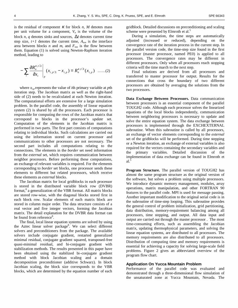
Figure 1a shows a scheme of partitioning a sample domaininto three parts. Gridblocks are assigned to particularprocessors through partitioning methods and reordered byeach processor to a local ordering. Elements corresponding tothese blocks are explicitly stored on the processor and aredefined by a set of indices referred to as the processor’supdate set. The update set is further divided into two subsets:internal and border. Vector elements of the internal set areupdated using only information on the current processor. Theborder set consists of blocks with at least one edge to a blockassigned to another processor. The border set includes blocksthat would require values from other processors to be updated.The set of blocks that are not in the current processor, butneeded to update components in the border set, is referred toas an external set. Table 1 shows the partitioning results andone of the local numbering schemes for the sample problempresented in Figure 1a.
The local numbering of gridblocks is done to facil itate thecommunication between processors. The numbering sequenceis internal blocks followed by border blocks and finall y by theexternal set. In addition, all external blocks from the sameprocessor are in consecutive order.
Similar to vectors, a subset of matrix with non-zero entriesis stored on each processor, In particular, each processor storesonly those rows, that correspond to its update set. These rowsform a submatrix whose entries correspond to variables ofboth the update set and the external set defined on thisprocessor.
Input Data Organization. The input data for reservoirsimulations include hydrogeologic parameters and constitutiverelations of porous media, such as absolute and relativepermeability, porosity, capillary pressure, thermophysicalproperties of fluid and rock, as well as initial and boundaryconditions of the system. In addition, a numerical coderequires specification of space-discretized geometricinformation (grid) and various program options such ascomputational parameters and time-stepping information. Fora typical, large-scale, three-dimensional model, computermemory of several gigabytes is generally required. Therefore,the need arises to distribute the memory requirement to allprocessors.
Each processor has a limited space of memory available.To make efficient use of the memory of each processor, theinput data files of the TOUGH2 code are organized insequential format. There are two groups of large data blockswithin a TOUGH2 mesh file: one with dimensions equal to thenumber of grid blocks, the other with dimensions equal to thenumber of connections (interfaces). Large data blocks are readone by one through a temporary full -size array and thendistributed to PEs one by one. This method avoids storing allinput data in a single processor and greatly enhances the I/Oefficiency. The I/O efficiency is further improved by storingthe input data in binary files. The data input procedures can beschematically outlined as follows:
In PE0:
Open a data file Read first parameter for all blocks (total NEL blocks)
into array Temp(NEL) Do i=1,TotalPEs Call MPI_SEND(…) to send the appropriate part of
Temp(NEL) to PEi. End do Read second parameter for all blocks into array
Temp(NEL) Do i=1,TotalPEs Call MPI_SEND(…) to send the appropriate part of
Temp(NEL) to PEi.End do ……. Repeat for all parameters that need to be read from data
file for all gridblocks. Read first parameter for all connections (NCON) into
array Temp(NCON) Do i=1,TotalPEs Call MPI_SEND(…) to send the appropriate part of
Temp(NCON) to PEi. End doRead second parameter all connections into Temp(NCON) Do i=1,TotalPEs Call MPI_SEND(…) to send the appropriate part of
Temp(NCON) to PEi. End do.…….Repeat for all parameters that need to be read from data
file for all connections.Close data file.
In PE1, PE2, ……, PEn: Allocate required memory space for current PE . Call MPI_RECV(…) to receive the part of data that
belongs to current PE from PE0.
Certain parts of the parallel code require full-connectioninformation, such as for domain partitioning and local-connection index searching. These parts can be the bottleneckof memory requirement for solving a large problem. Since thefull -connection information is used only once at the beginningof a simulation, it may be better handled in a preprocessingprocedure.
Assembly and Solution of Linear Equation Systems. Thediscrete mass and energy balance equations solved by theTOUGH2 code can be written in residual form:1,2
})({
)()()(
1,1
11
++
++
+∆−−=
∑ tnn
tnm
mnm
n
tn
tn
tn
qVxFAV
t
xMxMxR
κκ
κκκ
………….….…….(1)
where the vector xt consists of primary variables at time t, κnR
4 K. Zhang, Y. S. Wu, SPE, C. Ding, K. Pruess, SPE, and E. Elmroth SPE 66343
is the residual of component κ for block n, M denotes massper unit volume for a component, Vn is the volume of theblock n, q denotes sinks and sources, t∆ denotes current timestep size, t+1 denotes the current time, Anm is the interfacearea between blocks n and m, and Fnm is the flow betweenthem. Equation (1) is solved using Newton-Raphson iterationmethod, leading to
)()( ,1,
,1,
1,
pit
npipi
pi i
tn xRxxx
R ++
+
=−∂
∂− ∑ κ
κ
……(2)
where xi,p represents the value of ith primary variable at pthiteration step. The Jacobian matrix as well as the right-handside of (2) needs to be recalculated at each Newton iteration.The computational efforts are extensive for a large simulationproblem. In the parallel code, the assembly of linear equationsystem (2) is shared by all the processors. Each processor isresponsible for computing the rows of the Jacobian matrix thatcorrespond to blocks in the processor’s update set.Computation of the elements in the Jacobian matrix isperformed in two parts. The first part consists of computationsrelating to individual blocks. Such calculations are carried outusing the information stored on current processor andcommunications to other processors are not necessary. Thesecond part includes all computations relating to theconnections. The elements in the border set need informationfrom the external set, which requires communication betweenneighbor processors. Before performing these computations,an exchange of relevant variables is required. For the elementscorresponding to border set blocks, one processor sends theseelements to different but related processors, which receivethese elements as external blocks.
The Jacobian matrix for local gridblocks in each processoris stored in the distributed variable block row (DVBR)format,8 a generalization of the VBR format. All matrix blocksare stored row-wise, with the diagonal blocks stored first ineach block row. Scalar elements of each matrix block arestored in column major order. The data structure consists of areal vector and five integer vectors, forming the Jacobianmatrix. The detail explanation for the DVBR data format canbe found from reference8.
The final, local l inear equation systems are solved by usingthe Aztec linear solver package8. We can select differentsolvers and preconditioners from the package. The availablesolvers include conjugate gradient, restarted generalizedminimal residual, conjugate gradient squared, transposed-freequasi-minimal residual, and bi-conjugate gradient withstabil ization methods. The results presented in this paper havebeen obtained using the stabil ized bi–conjugate gradientmethod with block Jacobian scaling and a domaindecomposition preconditioner (additive Schwarz). In blockJacobian scaling, the block size corresponds to the VBRblocks, which are determined by the equation number of each
gridblock. Detailed discussions on preconditioning and scalingscheme were presented by Elmroth et al.5
During a simulation, the time steps are automaticall yadjusted (increased or reduced), depending on theconvergence rate of the iteration process in the current step. Inthe parallel version code, the time-step size found in the firstprocessor (master processor, named PE0) is applied to allprocessors. The convergence rates may be different indifferent processors. Only when all processors reach stoppingcriteria will the time march to the next step.
Final solutions are derived from all processors andtransferred to master processor for output. Results for theconnections that cross the boundary of two differentprocessors are obtained by averaging the solutions from thetwo processors.
Data Exchange Between Processors. Data communicationbetween processors is an essential component of the parallelTOUGH2 code. Although each processor solves the linearizedequations of the local blocks independently, communicationbetween neighboring processors is necessary to update andsolve the entire equation system. The data exchange betweenprocessors is implemented through the EXCHEXTERNALsubroutine. When this subroutine is called by all processors,an exchange of vector elements corresponding to the externalset of the gridblocks will be performed. During time steppingor a Newton iteration, an exchange of external variables is alsorequired for the vectors containing the secondary variables andthe primary variables. Detailed discussion of theimplementation of data exchange can be found in Elmroth etal.5
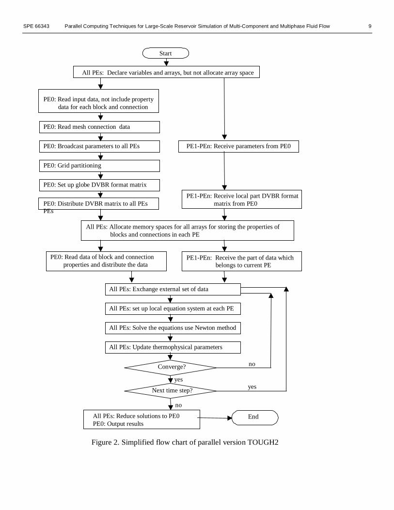
Program Structure. The parallel version of TOUGH2 hasalmost the same program structure as the original version ofthe software, but solves a problem using multiple processors.We introduce dynamic memory management, modules, arrayoperations, matrix manipulation, and other FORTRAN 90features to the parallel code. MPI is used for message passing.Another important modification to the original serial code is inthe subroutine of time-step looping. This subroutine providesthe general control of problem initialization, grid partitioning,data distribution, memory-requirement balancing among allprocessors, time stepping, and output. All data input andoutput are carried out through the master processor . The mosttime-consuming efforts, such as assembling the Jacobianmatrix, updating thermophysical parameters, and solving thelinear equation systems, are distributed to all processors. Thememory requirements are also distributed to all processors.Distribution of computing time and memory requirements isessential for achieving a capacity for solving large-scale fieldproblems. Figure 2 gives an abbreviated overview of theprogram flow chart.
Application On Yucca Mountain ProblemPerformance of the parallel code was evaluated anddemonstrated through a three-dimensional flow simulation ofthe unsaturated zone at Yucca Mountain, Nevada. The

SPE 66343 Parallel Computing Techniques for Large-Scale Reservoir Simulation of Multi-Component and Multiphase Fluid Flow 5
problem is based on the site-scale model developed forinvestigations of the unsaturated zone at Yucca Mountain,Nevada.9,10 It concerns unsaturated flow through fracturedrock using a 3-D, unstructured grid and a dual permeabil ityconceptualization for handling fracture-matrix interactions.The unsaturated zone of Yucca Mountain is being investigatedas a potential subsurface repository for storage of high-levelradioactive wastes. The model domain of the unsaturated zoneencompasses approximately 40 km2 of the Yucca Mountainarea, is between 500 and 700 m thick, and overlies a relativelyflat water table.
The 3-D model domain as well as a 3-D irregularnumerical grid used for this example is shown for a plan viewin Figure 3. The model grid uses relatively refined gridding inthe middle, repository area, and includes several nearlyvertical faults. The grid has about 9,800 blocks per layer forfracture and matrix continua, respectively, and about 60computational grid layers in the vertical direction, resulting ina total of 1,075,522 gridblocks and 4,047,209 connections. Adistributed-memory Cray T3E-900 computer equipped with695 processors has been used for the simulation. Eachprocessor has about 244 MB available memory and is capableof performing 900 milli on floating operations per second(MFLOPS).
The ground surface is taken as the top model boundary,and the water table is regarded as the bottom boundary. Bothtop and bottom boundaries of the model are assumedDirichlet-type conditions. In addition, on the top boundary, aspatially varying infiltration is applied to describe the netwater recharge, with an average infiltration rate of 4.6 mm/yrover the model domain.10 The properties used for rock matrixand fractures for the dual permeability model, including two-phase flow parameters of fractures and matrix, were estimatedbased on field tests and model calibration efforts, assummarized in Wu et al. 9
The linear equation system arising from the Newtoniteration of the Yucca Mountain problem is solved by thestabil ized bi-conjugate gradient method. A domaindecomposition-based preconditioner with ILUT incompleteLU factorization has been selected for preconditioning, andthe K-way partitioning algorithm has been selected forpartitioning the problem domain. The stopping criteria usedfor the iterative linear solver is
4
2
2 10−≤b
r…………………………………(3)
where ∑ ==
n
i irn1
2
2)/1(. , n is the total number of
unknowns, and r and b are the residual and right-hand side,respectively.
Two types of tests were run (1) to examine the accuracy ofthe parallel code, and (2) to evaluate the code performance andparallelization gains for different numbers of processors. Thefirst test simulates the flow system to steady state. The
simulation results for steady state flux through the repositoryand bottom layer are compared to results previously obtainedfrom simulations on a single-processor machine. The secondtest used different numbers of processors to simulate theunsaturated flow system for 200 time steps.
Steady State Test. The test problem was designed to test theaccuracy of solutions. We have verified the modeling resultsfrom the parallel code by comparing the solutions for asmaller grid model using a one-dimensional vertical column.The solutions for the smaller problem were obtained using theoriginal, single-CPU version and the parallel version of theTOUGH2 code. The test presented here provides a furtherverification of the code for large-scale simulations.
The 3-D test problem was run on 64 processors for 3,684time steps to reach steady state, recognized when the fluxesgoing into and leaving the flow system are equal (within anarrow difference). Because of the time limitation of thecomputer batch system, the whole simulation is divided intofive stages. Each stage runs about 700 time steps in less thanfour hours. The length of a total simulation time is about 1011
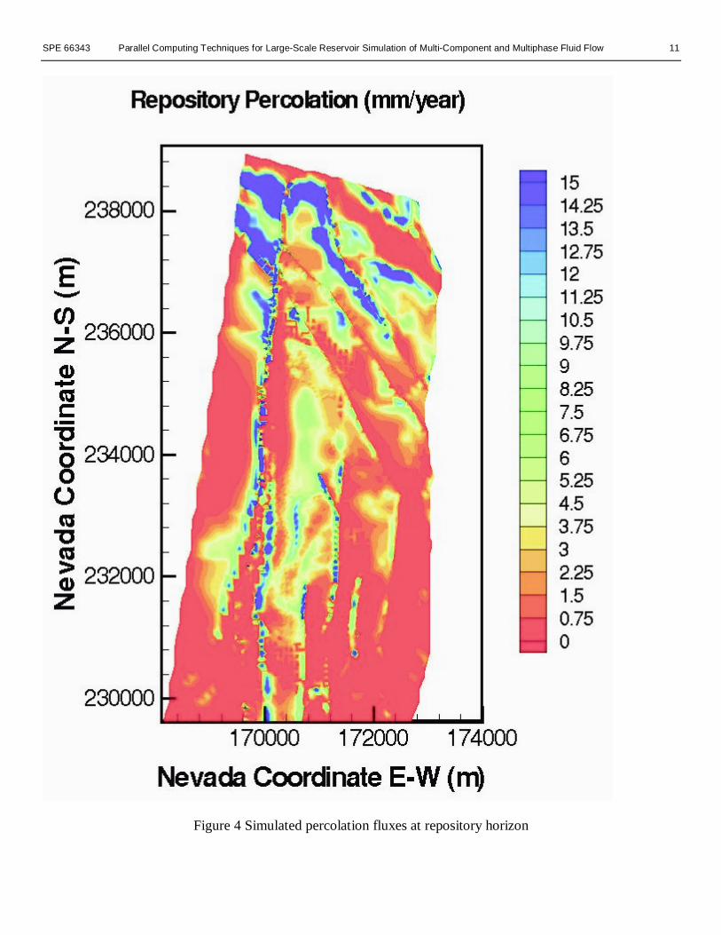
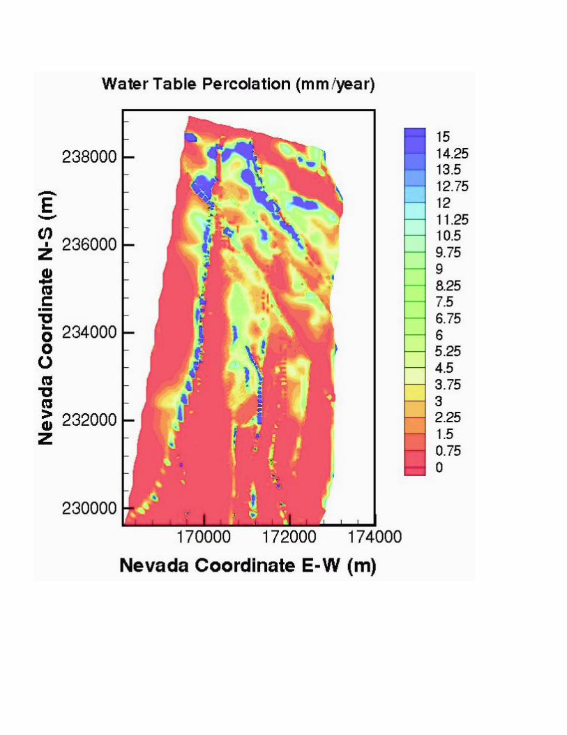
years when steady state is obtained.The percolation flux through the repository horizon and
below is one of the most important factors considered inevaluation of repository performance. Figures 4 and 5 showthe flux distributions along the repository horizon and at thebottom of the simulation domain (the water table). The darkcolor indicates higher values of percolation fluxes. The flux isdefined in the figures as total mass flux through both fracturesand matrix. Comparison of the simulation results (Figures 4and 5) against those using coarse-grid models10 indicates thatthe refined-grid model produces results with much higherresolution and more accurate flow distributions at therepository level as well as the water table. In particular, thecurrent, refined model predicts more significant lateral flow inthe upper part of the unsaturated zone, above the repositoryhorizon, due to using finer vertical grid spacings in theselayers. These modeling results wil l have direct impact onassessing repository performance. Further simulation resultswill be reported elsewhere.
Performance Test. In the second test, the problem was solvedusing 32, 64, 128, 256, and 512 processors, respectively.Because of the automatic time-step adjustment, based even onthe same convergence rate of the iteration process, the lengthof simulation times over 200 time steps using differentnumbers of processors may be different. However, thecomputational targets are similar, and comparing theperformance of different numbers of processors with the samenumber of time steps is reasonable for evaluating the parallelcode.
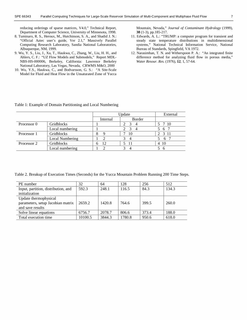
Table 2 shows the reduction in the total execution timewith an increase numbers of processors. The simulation wasrun on from 32 processors up to 512 processors byconsecutively doubling the number of processors. The resultsclearly indicate that the execution time is significantlyreduced, as the number of processors increases. Table 2 also

6 K. Zhang, Y. S. Wu, SPE, C. Ding, K. Pruess, SPE, and E. Elmroth SPE 66343
shows the time required for different computational tasksusing different numbers of processors. When less than 128processors are used, doubling the processor number willreduce the total execution time by more than half. From thetable, we can find that the best parallel performance is insolving-linear equation systems. Data input and output of theprogram are carried out through a single processor, which wil llimit the performance of the parallel code for those parts.
Figure 6 illustrates the speedup of the parallel code. Thespeedup is defined based on the performance of 32 processorsas 32T32/Tp, where Tp denotes the total execution time using pprocessors. The speedups from 32 to 64, 128, 256, and 512processors increase by factors of 2.63, 2.16, 1.87 and 1.54,respectively. Super-linear speedup appears during theprocessor number doubling from 32 to 64, and to 128 with aspeedup of 2.63 and 2.16. The overall speedup for 512processors is 523. The super-linear speedup is mostly due tothe preconditioner in solving linear equation system where thetime requirement is proportional to n2, with n being thenumber of gridblocks in each processor.
In contrast, the time requirement for the startup phase(input, partition, distribution, and initialization) in Table 2increases when the processor number is doubled from 256 to512 (instead of decreasing). It indicates that a saturation pointhas reached. This results from the increase of communicationoverhead when increasing the number of processors, whichcancels the time saving by requiring more processors in thisrange.
The partitioning algorithm can also significantly impactparallel code performance. The ideal case is that thegridblocks can be evenly distributed among the processorswith not only approximately the same number of internalgridblocks, but also roughly the same number of externalblocks per processor. For unstructured grids, this idealsituation may be difficult to achieve in practice. However, inour problem gridblocks are almost evenly divided amongprocessors. For example, on 128 processors, the averagenumber of internal blocks is 8,402 at each processor, themaximum number is 8,657 and minimum number is 8,156. Itis only about 6% different between the maximum andminimum number. A considerable imbalance arises for theexternal blocks. In this problem, the average number ofexternal blocks is 2,447, while the maximum number is aslarge as 3,650 and the minimum as small as 918. This largerange indicates that the communication volume can be fourtimes higher for one processor than another. The imbalance incommunication volume results in a considerable amount oftime wasted on waiting for certain processors to complete theirjobs during the solving of equation systems.
In general, the memory capacity of a single processor maybe too small to solve a problem with more than one milliongridblocks. The distribution of memory requirement among allthe processors will solve the storage problem of input data.For the Yucca Mountain one-milli on block problem, theparallel-computing performance is satisfactory for bothcomputation time and memory requirement.
ConclusionsMassive parallel computing technology has been implementedinto the TOUGH2 code for application to large-scale reservoirsimulations. In the parallel code, both computing efforts andmemory requirements are distributed among and shared by allprocessors of a multi-CPU computer. This parallel computingscheme makes it possible to solve large simulation problemsusing a parallel processor computer. The METIS graphpartitioning program was adopted for the grid partitioning, andthe Aztec package was used for solving the linear equationsystems.
The parallel TOUGH2 code has been tested on a Cray T3Esystem with 512 processors. Its performances are evaluatedthrough modeling flow in the unsaturated zone at YuccaMountain using different numbers of processors with morethan a million gridblocks. The total execution time is reducedfrom 10,101 seconds on 32 processors to 618 seconds on 512processors for the field-scale variably saturated flow problem.A super-linear speedup of 523 for 512 processors has beenreached. Test results indicate that the overall performance ofthe parallel code shows significant improvement in bothefficiency and abil ity for large-scale reservoir simulations.The major benefits of the code are that it (1) allows accuraterepresentation of reservoirs with suff icient resolution in space,(2) allows adequate description of reservoir heterogeneities,and (3) enhances the speed of simulation.
AcknowledgmentThe authors would li ke to thank Jianchun Liu and DanHawkes for their review of this paper. The authors are gratefulto Lehua Pan for his help in designing the 3-D grid used forthe test problem. This work was supported by the LaboratoryDirected Research and Development (LDRD) program ofLawrence Berkeley National Laboratory. The support isprovided to Berkeley Lab through the U. S. Department ofEnergy Contract No. DE-AC03-76SF00098.
References1. Pruess, K.: “TOUGH2 – A general-purpose numerical simulator
for multiphase fluid and heart flow,” Lawrence BerkeleyLaboratory Report LBL-29400, Berkeley, CA, 1991.
2. Pruess, K. Oldenburg, C., and Moridis, G.: “TOUGH2 User’sGuide, V2.0,” Lawrence Berkeley National Laboratory, Berkeley,CA, 1999.
3. Moridis, G. and Pruess, K.: “An enhanced package of solvers forthe TOUGH2 family of reservoir simulation codes,” Geothermics(1998) 27, No.4, 415-444.
4. Dogru, A. H.: “Megacell reservoir simulation,” JPT (MAY 2000),54-60.
5. Elmroth, E., Ding, C., and Wu, Y.: “High performancecomputations for large scale simulations of subsurface multiphasefluid and heat flow,” accepted by The Journal of Supercomputing,1999.
6. Message Passing Formum: “A message-passing interfacestandard,” International Journal of Supercomputing Applicationsand High performance Computing, 8(3-4), 1994.
7. Karypsis, G. and Kumar, V.: “A software package for partitioningunstructured graphs, partitioning meshes, and computing fill-
SPE 66343 Parallel Computing Techniques for Large-Scale Reservoir Simulation of Multi-Component and Multiphase Fluid Flow 7
reducing orderings of sparse matrices, V4.0,” Technical Report,Department of Computer Science, University of Minnesota, 1998.
8. Tuminaro, R. S., Heroux, M., Hutchinson, S. A., and Shadid J. N.:“Off icial Aztec user’s guide, Ver 2.1,” Massively ParallelComputing Research Laboratory, Sandia National Laboratories,Albuquerque, NM, 1999.
9. Wu, Y. S., Liu, J., Xu, T., Haukwa, C., Zhang, W., Liu, H. H., andAhlers, C. F.: “UZ Flow Models and Submodels,” Report MDL-NBS-HS-000006, Berkeley, Cali fornia: Lawrence BerkeleyNational Laboratory, Las Vegas, Nevada, CRWMS M&O, 2000
10. Wu, Y.S., Haukwa, C., and Bodvarsson, G. S.: “A Site-ScaleModel for Fluid and Heat Flow in the Unsaturated Zone of Yucca
Mountain, Nevada,” Journal of Contaminant Hydrology (1999),38 (1-3), pp.185-217.
11. Edwards, A. L.: “TRUMP: a computer program for transient andsteady state temperature distributions in multidimensionalsystems,” National Technical Information Service, NationalBureau of Standards, Spingfield, VA 1972.
12. Narasimhan, T. N. and Witherspoon P. A.: “An integrated finitedifference method for analyzing fluid flow in porous media,”Water Resour. Res. (1976), 12, 1, 57-64.
Table 1: Example of Domain Partitioning and Local Numbering
Update ExternalInternal Border
Gridblocks 1 2 3 4 5 7 10Processor 0Local numbering 1 2 3 4 5 6 7Gridblocks 8 9 7 10 2 3 11Processor 1Local Numbering 1 2 3 4 5 6 7Gridblocks 6 12 5 11 4 10Processor 2Local numbering 1 2 3 4 5 6
Table 2. Breakup of Execution Times (Seconds) for the Yucca Mountain Problem Running 200 Time Steps.
PE number 32 64 128 256 512Input, partition, distribution, andinitialization
592.3 248.1 116.5 84.3 134.3
Update thermophysicalparameters, setup Jacobian matrixand save results
2659.2 1420.8 764.6 399.5 260.0
Solve linear equations 6756.7 2078.7 806.6 373.4 188.0Total execution time 10100.5 3844.3 1780.8 950.6 618.0

8 K. Zhang, Y. S. Wu, SPE, C. Ding, K. Pruess, SPE, and E. Elmroth SPE 66343
1
2 3
4 5
6
7
89
10 11
12
(a) A 12-elements domain partitioning on 3 processors
(b) CSR format
Processor 0
Processor 2
Processor 1
Figure 1. An example of domain partitioning and CSR format for storing connections
Elements 1 2 3 4 5 6 7 8 9 10 11 12xadj 1 2 5 8 10 12 14 16 18 20 23 26 27adj 2 1,3,7 2,4,10 3,5 4,6 5,11 2,8 7,9 8,10 3,9,11 6,10,12 11
0
1 0 0
2 0 0
3 0 0
4 0 0
5 0 0
6 0 0
0 1 0 0 2 0 0 3 0 0 4 0 0 5 0 0 6 0 0
Nu m b e r o f p r o c e s s o r s
Spe
ed
up
F ig u re 6 . S p e ed u p fo r th e ap p lica tio n ex am p le o n th e C ray T 3 E -9 0 0
SPE 66343 Parallel Computing Techniques for Large-Scale Reservoir Simulation of Multi-Component and Multiphase Fluid Flow 9
All PEs: Declare variables and arrays, but not allocate array space
Start
PE0: Read input data, not include property data for each block and connection
PE0: Read mesh connection data
PE0: Broadcast parameters to all PEs PE1-PEn: Receive parameters from PE0
PE0: Grid partitioning
PE0: Set up globe DVBR format matrix
PE0: Distribute DVBR matrix to all PEsPEs
All PEs: Allocate memory spaces for all arrays for storing the properties of blocks and connections in each PE
PE1-PEn: Receive local part DVBR format matrix from PE0
PE0: Read data of block and connection properties and distribute the data
PE1-PEn: Receive the part of data which belongs to current PE
All PEs: Exchange external set of data
All PEs: set up local equation system at each PE
All PEs: Solve the equations use Newton method
All PEs: Update thermophysical parameters
Converge?
Next time step?
All PEs: Reduce solutions to PE0PE0: Output results
End
yes
no
no
yes
Figure 2. Simplified flow chart of parallel version TOUGH2

10 K. Zhang, Y. S. Wu, SPE, C. Ding, K. Pruess, SPE, and E. Elmroth SPE 66343
Figure 3 Plan view of the 3D simulation domain, gird and incorporated major faults
170000 172000 174000
230000
232000
234000
236000
238000
SeverWash
Fault
PaganyW
ashFaultD
rillholeW
ashFault
So
litar
ioC
anyo
nF
ault
Gho
stD
ance
Fau
lt
Imb
rica
teF
ault
Du
ne
Was
hF
ault
SPE 66343 Parallel Computing Techniques for Large-Scale Reservoir Simulation of Multi-Component and Multiphase Fluid Flow 11
Figure 4 Simulated percolation fluxes at repository horizon
12 K. Zhang, Y. S. Wu, SPE, C. Ding, K. Pruess, SPE, and E. Elmroth SPE 66343
Figure 5 Simulated percolation fluxes at bottom of the domain