spau 330 c overvoltage, undervoltage and … spau 330 c overvoltage, undervoltage and residual...
TRANSCRIPT

IRF
0008
A
[ ]s>t
0.5
0.05 1.0
50
10
0.5
0.05 1.0
2
10
20
STEP
RESET
SG1
0 1
12345678
STEP
>U >>U
SPCU 1C6
>>
[ ]s>>t
U o
nU>U o
nUUo 80
o o
[ ]%
[ ]%
U
∞
12 IRF
>U
23U 31UU
0013
A
[ ]sk
>t0.5
0.05 1.0
0.8
0.4
5.0
1.0 12
0.8
1.2
1.6
STEP
RESET
SG1
0 1
12345678
STEP
<U
nU>U
<t [ ]s
>U <U
SPCU 3C14
nU<U
1.2
>
SPCR 8C27
RESET
STEP
IRF
0035
A
TRIGGED / READY
U aux
Ser.No.
SPAU 330 C
80...265 V
18...80 V
2
5
0075
B
SGR
0 1
~–
U1 U2 U3
–
RS 613
Un=100V / 110V (U0 )
Un=100V / 110V (U )fn= 50Hz
60Hz
12345678
SPCU 1C6
12345
n )(U o>
/ >tt %[ ]>>/tt %[ ]
/ nU Uo %[ ]
>>n )(U o
SPCU 3C14
12345678
/ >tt %[ ]</tt %[ ]
n )(U >n )(U <
/ nU Umin
/ nU U<
/ nU U>
/ nU Umax
SPCR 8C27
STATUS
/ nU U12/ nU U23
/ nU U31
/ nU Uo %[ ]
n/II L1( )n/II L2( )n/II L3( )
n/II o %[ ]( )
123456789
0 0 00 0 0 00 0 0 00
SPAU 330 COvervoltage, undervoltageand residual voltage relay
User´s manual and Technical description

2
SPAU 330 COvervoltage,
undervoltage andresidual voltage relay
Contents Features .......................................................................................................................... 3Application ..................................................................................................................... 3Description of operation ................................................................................................. 4Connections ................................................................................................................... 5Operation indicators and push-buttons .......................................................................... 8Signal flow diagram and configuration switches .............................................................. 9Power supply module .................................................................................................... 11Output relay module .................................................................................................... 12Technical data (modified 2002-04) ................................................................................ 13Maintenance and repair ................................................................................................ 15Spare parts .................................................................................................................... 16Delivery alternatives ..................................................................................................... 16Dimension drawings and mounting.............................................................................. 17Order numbers and ordering information .................................................................... 18
The complete manual for the voltage measuring relay SPAU 330 C includesthe following submanuals:
Overvoltage, undervoltage and residual voltage relay manual,General part 1MRS 750508-MUM ENResidual overvoltage relay module SPCU 1C6 1MRS 750509-MUM ENOver- and undervoltage relay module SPCU 3C14 1MRS 750510-MUM ENDisturbance recorder module SPCR 8C27 1MRS 750511-MUM ENGeneral characteristics of C-type relay modules 1MRS 750328-MUM EN
1MRS 750508-MUM EN
Issued 1996-10-30Modified 2002-04-26Version B (replaces 34 SPAU 11 EN1)Checked MKApproved OL
Data subject to change without notice

3
Features Supervision and protection relay primarily usedfor supervision of substation busbar voltages
General-use voltage relay for applications requir-ing overvoltage or undervoltage supervision
Optional disturbance recorder module used forverifying the correct operation of the protec-tion relay and for analysing network operationquantities
Flexible selection of appropriate operational fea-tures in various applications
Local numerical display of setting values, meas-ured values, recorded fault values, auto-diagnos-tic fault codes, etc.
Serial interface for two-way data communicationwith substation level equipment via fibre-optic bus
Powerful software support for setting and moni-toring of the relay via a portable computer
Continuous self-supervision of relay hardwareand software with autodiagnosis for enhansedsystem reliability and availability
Robust aluminium relay case with IP54 degreeof protection by enclosure
High immunity to electrical and electromag-netic interference
CE marking according to the EC directive forEMC
Application The voltage measuring relay SPAU 330 C isintended for supervision and recording of phase-to-phase and residual voltages in substationbusbar sytems. The relay forms an integratedprotection scheme which includes two measur-ing modules and a disturbance recorder mod-ule. The residual voltage of the busbar system ismeasured by the two-stage residual overvoltagerelay module SPCU 1C6. The phase-to-phasevoltages are supervised by the overvoltage and
undervoltage relay module SPCU 3C14. Fur-thermore, the protection relay package can beprovided with a disturbance recorder module,type SPCR 8C27, which records the voltagesmeasured by the relay and the starting condi-tions of the separate relay modules and stages.By means of an optional bus connection mod-ule the relay can be connected to the fibre-opticSPA-bus for serial data communication withsubstation level equipment.

4
Description ofoperation
When the residual voltage of the busbar systemexceeds the setting value of the low-set stage ofthe residual overvoltage relay module SPCU1C6, the overvoltage stage starts and simulta-neously starts the corresponding timing circuit.When the timing circuit has timed out, the re-lay module delivers a tripping signal to the out-put relays. The high-set stage of the residualovervoltage relay module operates in the sameway. When the setting value of the stage is ex-ceeded, it starts, simultaneously starting its tim-ing circuit, and when the set operating time haselapsed, it performs tripping.
When one of the phase-to-phase voltages of thebusbar system measured by the over- and und-ervoltage relay module SPCU 3C14 exceeds thesetting value of the overvoltage stage, the over-voltage stage starts and performs tripping whenthe set operating time has elapsed. Correspond-ingly, if one the phase-to-phase voltages meas-ured by the relay module falls below the settingvalue of the undervoltage stage, the timing cir-
cuit of the undervoltage stage starts. When thecircuit has timed out, the undervoltage stageperforms tripping.
To prevent unwanted operations during an auto-reclose sequence, the starting and tripping ofthe undervoltage stage of the over- and under-voltage relay module SPCU 3C14 can beblocked by turning switch SG1/6 on the frontpanel of the relay module into the position 1.This prevents any operation of the undervolt-age stage U< if the measured voltage falls to avalue below 0.2 x Un (see fig. 1).
Tripping of the undervoltage stage alone maybe blocked by applying an external blocking sig-nal on the relay.
NOTE!To enable this blocking function, switch 5 ofswitchgroup SGB on the PC-board of the over-and undervoltage relay module SPCU 3C14must be in the position 1.
Fig. 1. Operation diagram for the over- and undervoltage relay module SPCU 3C14 when thestarting of the undervoltage stage is blocked by switch SG1/6 = 1.
Explanations:U>/Un Setting of the overvoltage stageU</Un Setting of the undervoltage stageSS1 Starting of the overvoltage stageTS1 Tripping of the overvoltage stageSS2 Starting of the undervoltage stageTS2 Tripping of the undervoltage stage
In a fault situation the disturbance recordermodule SPCR 8C27 records the curve forms ofthe residual voltage and the phase-to-phase volt-age, and the startings of the protection stages ofthe relay modules. The recording operation ofthe module may be preset to start when certain
triggering conditions are fulfilled. Recordingmay take place both prior to a fault situationand after the fault has occured. The fault dataare made accessible either over the RS 232 Cserial port on the front panel of the recordermodule or over the SPA bus.

5
Connections
Fig. 2. Connection diagram for the overvoltage, undervoltage and residual voltage relay SPAU 330 C.
Uaux Auxiliary supply voltageA, B...F Output relaysIRF Self-supervision alarmSS1, SS2 Output signals for startingTS1, TS2 Output signals for trippingBS1 Blocking input signalSGR Switchgroup for programming of starting and tripping signalsU1 Residual overvoltage relay module SPCU 1C6U2 Over- and undervoltage relay module SPCU 3C14U3 Disturbance recorder module SPCR 8C27U4 Output relay module SPTR 6B3U5 Power supply moduleU6 Energizing input module SPTE 4B9SPA-ZC_ Bus connection moduleRx/Tx Optical fibre receiver (Rx) and transmitter (Tx) of the bus connection module

6
Fig. 3. Rear wiew of the overvoltage, undervoltage and residual voltage relay SPAU 330 C.

7
Specification of input and output terminals
Terminal Functionnumber
13-14 Phase-to-phase voltage U12 (100 V)13-15 Phase-to-phase voltage U12 (110 V)
NOTE!If the over- and undervoltage relay module SPCU 3C14 is programmed for single-phase operation, the voltage to be measured has to be connected to terminals13-14-15.
16-17 Phase-to-phase voltage U23 (100 V)16-18 Phase-to-phase voltage U23 (110 V)
19-20 Phase-to-phase voltage U31 (100 V)19-21 Phase-to-phase voltage U31 (110 V)
28-29 Residual voltage U0 (100 V)28-30 Residual voltage U0 (110 V)
10-11 External blocking signal BS1
61-62 Auxiliary supply voltage. The positive pole (+) of the DC supply is connected toterminal 61. The auxiliary supply voltage range is marked on the system frontplate of the relay.
63 Protection earth (PE)
65-66 Tripping output relay A (heavy-duty) for all stages, U0>, U0>>, U> and U<
67-68-69 Alarm signal output relay B for stages U0>>, U> and U<73-74-75 Alarm signal output relay C for stage U>76-77-78 Alarm signal output relay D for stage U<79-80-81 Alarm signal output relay E for stage U0>70-71-72 Self-supervision output relay F. In normal service conditions the contact gap 70-72 is
closed. In a fault situation the contact gap 71-72 closes.
NOTE!Detailed information about the programming of starting and tripping signals inswitchgroups SGB and SGR is given in the section "Intermodular control signalexchange".
The overvoltage, undervoltage and residualvoltage relay SPAU 330 C is connected to theoptical fibre communication bus by means of a9-pole D-type connector located in the centreof the rear panel of the relay and a matchingbus connection module SPA-ZC_. The opto-
connectors of the optical fibres are plugged intothe counter connectors Rx and Tx of the busconnection module and the optical fibres arelinked from one protection relay to another andto the control data communicator.

8
Operationindicators andpush-buttons
and set values of the module and for presen-tation of the values concerned on the displayof the module. The RESET push-button isused for resetting locally the red operationindicators for tripping. An unreset operationindicator does not affect the operation of therelay module and thus, the module isconstantely operative.
4. The front panel of the disturbance recordermodule is provided with a numerical display,two push-buttons marked STEP and RESET,a 25-pole RS 232 C port connector and a LEDoperation indicator. The parameters meas-ured by this module can be scanned and setby means of the STEP and RESET push-buttons, in the same way as with the othermeasuring relay modules. Normally the op-eration indicator of the disturbance recorderis dark. When the module is recording infor-mation, the operation indicator is lit with agreen light and when the recording is com-pleted and data is stored in the memory, theoperation indicator turns red. The red op-eration indicator is lit as long as there is datastored in the recording memory of the mod-ule. The recorded data is made accessible ei-ther over the RS 232 C serial port on thefront panel of the recorder module or overthe SPA bus.
5. The front panels of the relay modules andthe disturbance recorder module are providedwith a red LED used as a self-supervisionalarm indicator IRF which indicates that theself-supervision system has detected a perma-nent fault in the protection relay. Further, therelay modules are provided with separateLED indicators on the front panel for indi-cation of the measured residual and phase-to-phase voltages.
6. The cover of the protection relay case is madeof transparent, UV-stabilized polycarbonatepolymer and provided with three push-but-tons for scanning of the relay parameters bymeans of the separate displays of the mod-ules and the STEP push-buttons inside thecover. To enable resetting of the modules bymeans of the RESET push-buttons, the coverof the relay case must be opened using thelocking screws for the case.
Detailed operation instructions are given in themanuals describing the individual relay mod-ules and in the document "General characteris-tics of C-type relay modules".
Fig. 4. System front panel of the overvoltage,undervoltage and residual voltage relay SPAU330 C.
1. The green LED Uaux on the system panel islit when the power supply of the relay is op-erating.
2. The relay modules are provided with twooperating stages and each stage has its ownyellow/red LED operation indicator. The op-eration indicator goes on with a yellow lightwhen the operation stage starts and with ared light if the stage delivers a tripping signalas well. The LED indicators can be given self-reset or manual reset mode of operation. Nor-mally, when the stage resets, the red opera-tion indicator remains lit after being switchedon to indicate by whitch stage the trippingwas initiated.
3. The front panels of both relay modules areprovided with a numerical display for indi-cation of measured and set values, two push-buttons marked STEP and RESET, a pro-gramming switchgroup SG1 for selection ofrelay functions and four setting knobs for op-eration values. The STEP push-button canbe used for scanning through the measured
U aux
Ser.No.
SPAU 330 C
80...265 V
18...80 V
2
5
0075
B
SGR
0 1
~–
U1 U2 U3
–
RS 613
Un=100V / 110V (U0 )
Un=100V / 110V (U )fn= 50Hz
60Hz
12345678
SPCU 1C6
12345
n )(U o>
/ >tt %[ ]>>/tt %[ ]
/ nU Uo %[ ]
>>n )(U o
SPCU 3C14
12345678
/ >tt %[ ]</tt %[ ]
n )(U >n )(U <
/ nU Umin
/ nU U<
/ nU U>
/ nU Umax
SPCR 8C27
STATUS
/ nU U12/ nU U23
/ nU U31
/ nU Uo %[ ]
n/II L1( )n/II L2( )n/II L3( )
n/II o %[ ]( )
123456789
0 0 00 0 0 00 0 0 00

9
Signal flowdiagram andconfigurationswitches
The internal signals of the overvoltage, under-voltage and residual voltage relay SPAU 330 Cand the configuration switches are illustrated infig. 5.
In certain applications it may be necessary toalter the factory settings of the configurationswitches to obtain the required control signalsand function of the protection relay.
BS
1
Uo
23
45
67
81
Uo>
Uo>
>
t>t>
>
TS
1T
S2
23
45
67
81
t>
SS
1S
S2
TS
1T
S2
U> k>
U< t<
SG
BS
GB
SPCU 1C6 (U1)
SPCU 3C14 (U2)
SPCR 8C27 (U3)
SG
R
1 2 3 4 5 6 7 8
B C D EA
U12
,U
23,
U31
ST
6
ST
1
ST
3
ST
2
Fig. 5. Internal control signals between the relay modules of the overvoltage, undervoltage andresidual voltage relay SPAU 330 C.

10
Configurationswitches
Part of the starting and tripping signals fromthe relay modules are permanently connectedto control the output relays, whereas part of thecontrol signals are linked through the configu-ration switches of switchgroup SGR on the sys-tem panel of the relay. The programming ismade through the opening in the system panel.
The switchgroups SGB on the PC-boards of therelay modules SPCU 1C6 and SPCU 3C14 areused for programming of the external blockingsignals to the relay modules and the starting sig-nals connected to the disturbance recorder mod-ule SPCR 8C27.
The functions of the switchgroups SGB andSGR are described in the tables as follows:
Switchgroup SGR on relay system panel
Switch Function Factorysetting
SGR/1 Tripping signal from stage U> of SPCU 3C14 to output relay A 1SGR/2 Tripping signal from stage U< of SPCU 3C14 to output relay A 1SGR/3 Tripping signal from stage U0> of SPCU 1C6 to output relay A 1SGR/4 Tripping signal from stage U0>> of SPCU 1C6 to output relay A 1SGR/5 Tripping signal from stage U> of SPCU 3C14 to output relay B 1SGR/6 Tripping signal from stage U< of SPCU 3C14 to output relay B 1SGR/7 Starting signal from stage U> of SPCU 3C14 to output relay C 1SGR/8 Starting signal from stage U< of SPCU 3C14 to output relay D 1
Switchgroup SGB on PC-board in residual overvoltage relay module SPCU 1C6
Switch Function Factorysetting
SGB/1 Starting signal from stage U0> to input ST2 of disturbance recordermodule SPCR 8C27 1
SGB/2 Starting signal from stage U0>> to input ST2 of disturbance recordermodule SPCR 8C27 0
SGB/3 Starting signal from stage U0>> to input ST3 of disturbance recordermodule SPCR 8C27 0
SGB/4 Blocking signal BS1 for blocking of U0>-tripping 0SGB/5 Blocking signal BS1 for blocking of U0>>-tripping 0SGB/6 Not in use 0SGB/7 Not in use 0SGB/8 Not in use 0
Switchgroup SGB on PC-board in over- and undervoltage relay module SPCU 3C14
Switch Function Factorysetting
SGB/1 Starting signal from stage U> to input ST1 of disturbance recordermodule SPCR 8C27 1
SGB/2 Starting signal from stage U< to input ST1 of disturbance recordermodule SPCR 8C27 0
SGB/3 Starting signal from stage U< to input ST3 of disturbance recordermodule SPCR 8C27 1
SGB/4 Not in use 0SGB/5 Blocking signal BS1 for blocking of U<-tripping 1SGB/6 Not in use 0SGB/7 Not in use 0SGB/8 Not in use 0

11
Power supplymodule
The power supply module is located behind thesystem front panel of the relay together withthe output relay module. The supply module isa separate relay module and can be withdrawnafter removal of the system front panel. Thepower supply module produces the voltages re-quired by the relay modules from the auxiliarysupply voltage.
There are two types of power supply modules,differing only in input voltage:
SPGU 240 A1:Nominal voltage Un = 110/120/230/240 V ac
Un = 110/125/220 V dcOperative range U = 80...265 V ac/dc
SPGU 48 B2:Nominal voltage Un = 24/48/60 V dcOperative range U = 18...80 V dc
The power supply type is marked on the systemfront panel.
The power supply module is a transformer con-nected, i.e. galvanically separated primary andsecondary circuits, flyback type rectifier. Theprimary circuit is protected by a fuse F1, 1A(slow) in SPGU 240 A1 and 4A (fast) in SPGU48 B2, which are located on the printed circuitboard of the module.
When the power supply is on, a green LED in-dicator Uaux is lit on the system panel. The su-pervision of the supply voltages for the electron-ics is located on the regulating modules. Theself-supervision alarm is given if any of the sec-ondary voltages differ more than 25% from thenominal value. Also, if the power supply mod-ule is missing, or if there is no auxiliary supplyto the voltage regulator at all, an alarm is given.

12
Output relaymodule
The output relay module SPTR 6B3 is locatedbehind the system front panel of the relay to-gether with the power supply module. The out-put relay module forms its own withdrawablerelay module after removal of the system front
plate. The module contains all output relays,A...F, the control circuits of the relays as well asthe electronic circuitry of the external controlinputs.
Fig. 6. Block diagram for the output relay module SPTR 6B3.
TS1/U1 Tripping signal of U0>-stageTS2/U1 Tripping signal of U0>>-stageSS1/U2 Starting signal of U>-stageTS1/U2 Tripping signal of U>-stageSS2/U2 Starting signal of U<-stageTS2/U2 Tripping signal of U<-stageBS1 External blocking input signal to U<-stageA Tripping output relay A (heavy-duty) for all stages, U0>, U0>>, U> and U<B Alarm signal output relay B for stages U0>>, U> and U<C Alarm signal output relay C for stage U>D Alarm signal output relay D for stage U<E Alarm signal output relay E for stage U0>F Self-supervision output relay FIRF Self-supervision input signalSGR Switchgroup for programming of starting and tripping signalsENA Enable output signal from control circuits
The input and output signals of the output re-lay module are related to the fixed positions ofthe relay modules which cannot be changed inthe relay housing. The output signals from eachrelay module and PC-board location are wiredindividually to the output relay module. It must
be pointed out that the relay modules have tobe plugged into the relay case as illustrated inthe figure on the front page in order to securethat the connection diagram drawn for the re-lay assembly also would correspond to the physi-cal function of the protective device.

13
Technical data(modified 2002-04)
Energizing inputsRated voltage Un 100 V 110 VTerminal numbers- phase-to-phase voltage U12 13-14 13-15- phase-to-phase voltage U23 16-17 16-18- phase-to phase voltage U31 19-20 19-21- residual voltage U0 28-29 28-30Continuous voltage withstand 2 x UnRated burden at rated voltage Un <0.5 VARated frequency fn according to order 50 Hz or 60 Hz
External control inputsTerminal numbers 10-11External control voltage 18...265 V dc or 80...265 V acCurrent drain, typically 2...15 mA
Contact outputsTripping outputsTerminal numbers- trip relay A 65-66Rated voltage 250 V ac and dcContinuous current carrying capacity 5 AMake and carry for 0.5 s 30 AMake and carry for 3 s 15 ABreaking capacity for dc when the control circuittime constant L/R ≤40 ms at 48/110/220 V dc 5 A / 3 A / 1 ASignalling outputsTerminal numbers- alarm relay B 67-68-69- alarm relay C 73-74-75- alarm relay D 76-77-78- alarm relay E 79-80-81- self-supervision relay F 70-71-72Rated voltage 250 V ac and dcContinuous current carrying capacity 5 AMake and carry for 0.5 s 10 AMake and carry for 3 s 8 ABreaking capacity for dc when the control circuittime constant L/R ≤40 ms at 48/110/220 V dc 1 A / 0.25 A / 0.15 A
Auxiliary power supplyVoltage range of power supply modules:SPGU 240 A1- Nominal voltage Un 110/120/230/240 V ac
110/125/220 V dc- Operative range 80...265 V ac/dcSPGU 48 B2- Nominal voltage Un 24/48/60 V dc- Operative range 18...80 V dcPower consumption under quiescent/operation conditions 10 W / 15 W

14
Residual overvoltage relay module SPCU 1C6See "Technical data" in the document 1MRS 750509-MUM EN for the relay module.
Over- and undervoltage relay module SPCU 3C14See "Technical data" in the document 1MRS 750510-MUM EN for the relay module.
Disturbance recorder module SPCR 8C27See "Technical data" in the document 1MRS 750511-MUM EN for the recorder module.
Data communicationTransmission mode Fibre-optic serial busCoding ASCIIData transfer rate, selectable 300, 1200, 2400, 4800 or 9600 BdOptical bus connection module powered fromthe host relay- for plastic-core cables SPA-ZC 21 BB- for glass-fibre cables SPA-ZC 21 MMOptical bus connection module powered fromthe host relay or from an external power source- for plastic-core cables SPA-ZC 17 BB- for glass-fibre cables SPA-ZC 17 MM
Insulation Tests *)Dielectric test IEC 60255-5 2 kV, 50 Hz, 1 minImpulse voltage test IEC 60255-5 5 kV, 1.2/50 µs, 0.5 JInsulation resistance measurement IEC 60255-5 >100 MΩ, 500 Vdc
Electromagnetic Compatibility Tests *)High-frequency (1 MHz) burst disturbance testIEC 60255-22-1- common mode 2.5 kV- differential mode 1.0 kVElectrostatic discharge test IEC 60255-22-2 andIEC 61000-4-2- contact discharge 6 kV- air discharge 8 kVFast transient disturbance test IEC 60255-22-4and IEC 61000-4-4- power supply 4 kV- I/O ports 2 kV

15
Emission testsRadiated and conducted emission accordingto EN 55011 Class A
EMC testsCE approved and tested according toEN 50081-2 and EN 50082-2
Environmental conditionsService temperature range -10...+55°CTemperature dependence <0.2%/°CTransport and storage temperature rangeaccording to IEC 60068-2-8 -40...+70°CDamp heat test according to IEC 60068-2-30 ≤95%, 55°C, 6 cyclesDegree of protection by enclosure of flush mountingrelay case according to IEC 60529 IP54Weight of fully equipped relay 5.5 kg
*) The tests do not apply to the serial port, which is used exclusively for the bus connection module.
Maintenanceand repair
When the overvoltage, undervoltage and re-sidual voltage relay SPAU 330 C is operatingunder the conditions specified in "Technicaldata", the relay requires practically no mainte-nance. The voltage relay includes no parts orcomponents that are sensitive to physical or elec-trical wear under normal operating conditions.
Should the temperature and humidity at theoperating site differ from the values specified,or the atmosphere contain chemically activegases or dust, the relay should be visually in-spected in association with the secondary test-ing of the relay. This visual inspection shouldfocus on:
- Signs of mechanical damage to relay case andterminals
- Collection of dust inside the relay case; removewith compressed air
- Signs of corrosion on terminals, case or insidethe relay
If the relay malfunctions or the operating val-ues differ from those specified, the relay shouldbe overhauled. Minor measures can be taken bythe customer but any major repair involving theelectronics has to be carried out by the manu-facturer. Please contact the manufacturer or hisnearest representative for further informationabout checking, overhaul and recalibration ofthe relay.
The protection relay contains circuits sensitiveto electrostatic discharge. If you have to with-draw a relay module, ensure that you are at thesame potential as the module, for instance, bytouching the case.
Note!Protective relays are measuring instruments andshould be handled with care and protectedagainst moisture and mechanical stress, espe-cially during transport.

16
Spare parts Residual overvoltage relay module SPCU 1C6Over- and undervoltage relay module SPCU 3C14Disturbance recorder module SPCR 8C27Power supply modules- Uaux = 80...265 V ac/dc (operative range) SPGU 240 A1- Uaux = 18...80 V dc (operative range) SPGU 48 B2Output relay module SPTR 6B3Interface module SPTE 4B9Case (including connection module) SPTK 4B9Bus connection module SPA-ZC 17_ or SPA-ZC 21_
Deliveryalternatives
Type Equipment SPCU SPCU SPCR1C6 3C14 8C27
SPAU 330 C Basic version, all relay modules included x x x
SPAU 330 C1 Basic version, disturbance recorder module x xexcluded
SPAU 330 C2 Basic version, over- and undervoltage relay x xmodule excluded
SPAU 330 C3 Basic version, over-and undervoltage relay xmodule and disturbance recorder module excluded
SPAU 330 C4 Basic version, residual overvoltage relay module x xexcluded
SPAU 330 C5 Basic version, residual overvoltage relay module xand disturbance recorder module excluded
SPAU 330 C6 Basic version, residual overvoltage relay module xand over- and undervoltage relay module excluded
Delivery alternatives of overvoltage, undervoltage and residual voltage relay SPAU 330 C.

17
Dimensiondrawingsand mounting
The basic model of the protection relay case isdesigned for flush-mounting. When required,the mounting depth of the case can be reducedby using raising frames: type SPA-ZX 301 re-duces the depth by 40 mm, type SPA-ZX 302
by 80 mm and type SPA-ZX 303 by 120 mm.When projecting mounting is preferred a relaycase type SPA-ZX 306 is used. The relay casefor projecting mounting is provided with frontconnectors.
Raising frame
SPA-ZX 301SPA-ZX 302SPA-ZX 303
219179139
74114154
a b
226
162
136
229
293259
3034
a b
Panel cut-out
214 ±1
139
±1
Fig. 7. Dimension and mounting drawings for overvoltage, undervoltage and residual voltagerelay SPAU 330 C.
The relay case is made of profile aluminium andfinished in beige.
The rubber gasket fitted to the mounting collarprovides an IP54 degree of protection by enclo-sure between the relay case and the mountingbase.
The hinged cover of the case is made of trans-parent, UV-stabilized polycarbonate polymerand provided with two sealable locking screws.The rubber gasket of the cover provides an IP54degree of protection between the case and thecover.
The required input and output connections aremade to the multi-pole terminal blocks on the
rear panel. Each screw terminal is dimensionedfor one or two wires of maximum 2.5 mm2. Aconnection diagram adjacent to the terminalblocks illustrates the connection of the termi-nals.
The 9-pole D-type connector is intended forserial communication of the relay. A 25-pole D-type connector is used for connecting the dis-turbance recorder module via the RS 232 C porton the front panel to an output device.
The bus connection modules (SPA-ZC 17_ orSPA-ZC 21_) and fibre-optic cables recom-mended by the manufacturer should always beused for the serial communication.

18
Order numbersand orderinginformation
Overvoltage, undervoltage and residual voltage relay
SPAU 330 C RS 613 020 - AA, CA, DA, FASPAU 330 C1 RS 613 021 - AA, CA, DA, FASPAU 330 C2 RS 613 022 - AA, CA, DA, FASPAU 330 C3 RS 613 023 - AA, CA, DA, FASPAU 330 C4 RS 613 024 - AA, CA, DA, FASPAU 330 C5 RS 613 025 - AA, CA, DA, FA
The letter combinations of the order number denote the rated frequency fn andthe operative range of the auxiliary supply voltage:
AA: fn = 50 Hz, Uaux = 80...265 V ac/dcCA: fn = 50 Hz, Uaux = 18...80 V dcDA: fn = 60 Hz, Uaux = 80...265 V ac/dcFA: fn = 60 Hz, Uaux = 18...80 V dc
Ordering example:
1. Number and type designation 5 pcs SPAU 330 C2. Order number RS 613 020 - AA3. Rated frequency fn = 50 Hz4. Auxiliary voltage Uaux = 110 V dc5. Accessories 5 raising frames SPA-ZX 301
5 bus connection modules SPA-ZC 17 MM2A6. Special requirements –

IRF
1310
[ ]s>t
0.5
0.05 1.0
50
10
0.5
0.05 1.0
2
10
20
STEP
RESET
SG1
0 1
12345678
>U >>U
SPCU 1C6
B
>>
[ ]s>>t
U o
nU>U o
nUUo 80
o o
[ ]%
[ ]%
U
STEP
SPCU 1C6Residual overvoltage relay module
User´s manual and Technical description

2
SPCU 1C6Residual overvoltage
relay module
Contents Features .......................................................................................................................... 2Description of operation ................................................................................................. 3Block diagram................................................................................................................. 4Front panel ..................................................................................................................... 5Operation indicators ....................................................................................................... 5Settings ........................................................................................................................... 6Selector switches ............................................................................................................. 6Measured data................................................................................................................. 7Recorded information ..................................................................................................... 8Menu chart ..................................................................................................................... 9Technical data ............................................................................................................... 10Serial communication parameters ................................................................................. 11
Event codes .............................................................................................................. 11Data to be transferred over the serial bus ................................................................. 12
Fault codes .................................................................................................................... 15
Features Low-set residual overvoltage stage U0> withdefinite time operation characteristic, settingranges 2...20% x Un and 10...100% x Un
High-set residual overvoltage stage U0>> withdefinite time operation characteristic, settingranges 10...80% x Un or 2...16% x Un
The operation of the high-set residual over-voltage stage can be set out of function by se-lecting the setting ∞, infinitive
Effective suppression of harmonics of the inputenergizing voltages
Local display of measured and set values as wellas data recorded at the moment of a relay op-eration
Flexible selection of special operational featuresfor particular applications
Continuous self-supervision of hardware andsoftware. At a permanent fault the alarm out-put relay picks up and the other outputs areblocked.
1MRS 750509-MUM EN
Issued 96-12-02Version A (replaces 34 SPCU 2 EN1)Checked L-W UApproved TK
Data subject to change without notice

3
Description ofoperation
The residual overvoltage relay module typeSPCU 1C6 is used in a variety of different pro-tection relay units where it constitutes a non-directional general earth-fault protection mod-ule which measures the residual voltage of theelectrical power system.
The residual overvoltage module contains twoovervoltage stages,that is a low-set stage U0> anda high-set stage U0>>.
The low-set or high-set voltage stage starts ifthe measured voltage exceeds the set start valueof the stage concerned. When starting, the con-cerned stage delivers a starting signal SS1 or SS2and simultaneously the operation indicator ofthe stage is lit with yellow colour. If the over-voltage situation lasts long enough to exceed theset operation delay, the stage that started alsooperates generating a trip signal, TS1 alt. TS2.The operation indicator of the stage that oper-ated turns red. The start and operation indica-tors are provided with memory control, whichmeans that they can be given the self-reset orthe latching mode of operation. The latchingindicators are reset with the RESET push-but-ton on the front panel or by means of the com-mand V101 or V102 via the serial port.
The tripping of the low-set overvoltage stageU0> can be blocked by routing a blocking sig-nal BTS1 to the low-set stage. Similarly, the trip-ping of the high-set stage U0>> is blocked by ablocking signal BTS2. The blocking signals arerouted by means of switchgroup SGB on thePC board of the relay module.
The setting range of the operation time t> ofthe low-set overvoltage stage U0> is selected withswitches SG1/1 and SG1/2. Three setting rangesare available.
Switches SG1/7 and SG1/8 are used for select-ing the setting range for the operation time t>>of the high-set stage U0>>. Three setting rangesare available.
The setting range of the start value of the low-set stage U0> is selected with switch SG1/5. Twosetting ranges are available, that is 2...20% x Unand 10...100% x Un.
The setting range of the start value of the high-set stage U0>> is selected with switch SG1/6. Twosetting ranges are available, that is 2...16% x Unor 10...80% x Un.
The operation of the two operating stages isprovided with a so called latching facility, whichmeans that the operation output is kept alerted,although the signal which caused the operationdisappears. The latching function is selectedwith switch SG1/4. The latched output and theoutput relay can be reset in three different ways;(i) by pressing push buttons STEP and RESETsimultaneously, (ii) via the serial inter-face us-ing the command V101 or (iii) via the serialinterface using the command V102. When al-ternative (ii) is used all recorded information ismaintained but if the alternatives (i) or (iii) isused the recorded information is erased.
The residual voltage signal input is providedwith an effective filter by means of whichhamonics of the measured residual voltage issuppressed, see Fig. 1.
dB 10
0
-10
-20
-30
-40
-50
-600 1 2 3 4 5 6 7 f / fn
Fig. 1. Filter characteristics of the residual volt-age input circuit.

4
Block diagram
Fig. 2. Block schematic diagram of the residual overvoltage relay module SPCU 1C6.
U0 Measured residual voltageBS1, BS2, BS3 Incoming external blocking signalsBTS1 Blocking of tripping of stage U0>BTS2 Blocking of tripping of stage U0>>SG1 Selector switchgroup on the relay module front panelSG2 Function selector switchgroup for the operation indicatorsSGB Selector switchgroup on the PC board for blocking signalsSS1 Start signal of stage U0>TS1 Trip signal of stage U0>SS2 Start signal of stage U0>>TS2 Trip signal of stage U0>>Y Yellow indicator, startingR Red indicator, tripping
NOTE!All input and output signals of the relay mod-ule are not necessarily wired to the terminals ofevery protection relay unit utilizing this mod-
ule. The signals wired to the terminals are shownin the signal diagram in the manual of the con-cerned protection relay unit.

5
Front panel
Voltage measurement indicator
Start voltage setting knoband indicator of stage U0>
Operation time setting knoband indicator of stage U0>
Start voltage setting knob andindicator of stage U0>>
Operation time setting knoband indicator of stage U0>>
IRF
1310
[ ]s>t
0.5
0.05 1.0
50
10
0.5
0.05 1.0
2
10
20
STEP
RESET
SG1
0 1
12345678
>U >>U
SPCU 1C6
B
>>
[ ]s>>t
U o
nU>U o
nUUo 80
o o
[ ]%
[ ]%
U
STEP
Simplified device symbol
Self-supervision alarmindicator
Display for set andmeasured values
Display step push-button
Selector switchgroup
Switchgroup indicator
Reset push-button
Operation indicators
Relay module typedesignation
Fig. 3. Front panel of the residual overvoltage relay module SPCU 1C6.
Operationindicators
Both voltage stages have their own yellow/redLED indicators. Yellow light indicates startingof the concerned overvoltage stage and red lightindicates that the overvoltage stage has operated.
The four LED indicators can, independently ofone another, be given a non-latching or a latch-ing mode of operation. The latching modemeans that the indicator remains lit after beingswitched on, although the overvoltage stage,which controls the indicator, resets. If, for in-stance, the yellow start indicator is given thelatching mode and the red indicator the non-latching mode, the yellow indicator is lit, whenthe stage starts, which then turns red if and whenthe stage operates. When the overvoltage stageresets only the yellow indicator remains lit. Theindicators, which have been given the latchingmode, are reset locally by pushing the RESETpush-button or by remote control over the SPAbus using the command V102.
An unreset operation indicator does not affectthe protective functions of the relay module.
The self-supervision alarm indicator IRF indi-cates that the self-supervision system has de-tected a permanent internal relay fault. The in-dicator is lit with red light shortly after the faulthas been detected. At the same time the relaymodule puts forward a control signal to the self-supervision system output relay of the protec-tion relay unit.
Additionally, in most fault cases, a fault codeshowing the nature of the fault appears on thedisplay of the module. The fault code, consist-ing of a red number one (1) and a green three-digit code number, indicates what type of in-ternal fault that has been detected. When a faultmessage appears, the fault code should be noteddown for later use when relay overhaul or re-pair is to be carried out.

6
Settings The setting values are shown by the threerightmost digits of the display. A LED indica-
tor below the setting knob shows, when lit,which setting value is presented on the display.
U0>/Un Start voltage value of the U0> stage, expressed as a percentage of the rated voltageof the energizing input used. The setting range is 2...20% x Un when SG1/5 = 0,and 10...100% x Un when SG1/5 = 1.
t> [s] Operate time of the U0> stage, expressed in seconds. The setting range is deter-mined by the position of switches SG1/1 and SG1/2. Selectable operate time set-ting ranges 0.05...1.00 s, 0.5...10.0 s and 5...100 s.
U0>>/Un Start voltage value of the U0>> stage, expressed as a percentage of the rated voltageof the energizing input used. The setting range is 10...80% x Un when SG1/6 = 0,and 2...16% x Un when SG1/6 = 1. The setting ∞, infinite, (displayed as - - -) setsthe high-set stage U0>> out of operation.
t>> [s] Operate time of the U0>> stage, expressed in seconds. The required setting range,0.05...1.00 s, 0.5...10.0 s or 5.00...100 s, is selected with switches SG1/7 andSG1/8.
Further, the checksum of the selector switch-group SG1 is shown on the display when theLED indicator below the switchgroup is lit. Bymeans of the displayed checksum and thechecksum manually calculated the proper op-
eration of the switchgroup SG1 can be verified.An example of how the checksum is calculatedis shown in the manual "General characteristicsof C type relay modules".
Selector switches Additional functions required by individualapplications are selected by means of the func-tion selector switches of switchgroup SG1 lo-cated on the front panel. The numbering of the
switches, 1...8, as well as the switch positions 0and 1 are marked on the relay module frontpanel.
Switch Function
SG1/1 Selection of setting range for the operate time t> of low-set stage U0>.SG1/2
SG1/1 SG1/2 Operate time t>
0 0 0.05...1.00 s1 0 0.5...10.0 s0 1 0.5...10.0 s1 1 5...100 s
SG1/3 Not in use. Has to be set in position 0.
SG1/4 Selection of latching function for the tripping signals TS1 and TS2.
When SG1/4 = 0, the trip signals reset to the initial state (= the output relay drops off ),when the measuring signal causing the operation falls below the set start voltage level.When SG1/4 = 1, the trip signals remain activated (= the output relay remains pickedup), although the measuring signal falls below the set start voltage level. Then the tripsignals are reset by pressing the push-buttons STEP and RESET simultaneously orwith the commands V101 or V102 via the serial port.
SG1/5 Selection of setting range for the start voltage value of the low-set stage U0>.
When SG1/5 = 0, the setting range is 2...20% x Un.When SG1/5 = 1, the setting range is 10...100% x Un.

7
Switch Function
SG1/6 Selection of setting range for the start voltage value of the high-set stage U0>>.
When SG1/6 = 0, the setting range is 10...80% x Un and ∞, infinite.When SG1/6 = 1, the setting range is 2...16% x Un and ∞, infinite.
SG1/7 Selection of setting range for the operate time t>> of the high-set stage U0>>.SG1/8
SG1/7 SG1/8 Operate time t>>
0 0 0.05...1.00 s1 0 0.5...10.0 s0 1 0.5...10.0 s1 1 5...100 s
Switchgroup SG2 is a so called software switch-group, which is located in the third submenuof switchgroup SG1. The mode of operation,i.e. self-reset or manually reset, of the LED in-dicators U0> and U0>> is determined by theswitches of switchgroup SG2. The mode of op-
eration can be separately set for each indicator.The mode of operation is set by means of thechecksum, which can be calculated from thefollowing table. Normally the start indicationsare self-reset and the operation indicationsmanually reset.
Indicator Manually reset Factory default
Start indicator U0> 1 0Operation indicator U0> 2 2Start indicator U0>> 4 0Operation indicator U0>> 8 8
Checksum 15 10
The PC board of the relay module contains aswitchgroup SGB including switches 1...8. Theswitches 1...3 are used for selecting the startingsignals, whereas switches 4...8 are used for rout-ing the blocking signals to the voltage module
in various protection relay units. Instructionsfor setting of switchgroup SGB are given in theuser's manual of the different protection relayunits.
Measured data The measured values are displayed by the threerightmost digits on the display. The measured
data to be displayed are indicated by a lit LEDindicator.
Indicator Measured data
U0 Residual voltage measured by the relay module, expressed as a percentage of therated voltage of the energizing input used.

8
Recordedinformation
The leftmost red digit displays the addressnumber of the register, the rightmost three greendigits display the recorded data.
Register/ Recorded dataSTEP
1 Maximum residual voltage measured by the module, as a percentage of the ratedvoltage Un of the used energizing input. If the module operates, the voltage value atthe moment of operation is stored in the memory. Any new operation erases the oldvalue and updates the register with the new value. The same thing happens if themeasured voltage exceeds a previously recorded maximum value.
2 Number of starts of the low-set overvoltage stage U0>, n (U0>) = 0...255.
3 Number of starts of the high-set overvoltage stage U0>>, n (U0>>) = 0...255.
4 Duration of the latest start situation of stage U0> as a percentage of the set operatetime t>. Any new start resets the counter, which then starts counting from zero.When the stage has operated, the counter reading is 100.
5 Duration of the latest start situation of stage U0>> as a percentage of the set operatetime t>>. Any new start resets the counter, which then starts recounting from zero.When the stage has operated, the counter reading is 100.
0 Display of blocking signals and other external control signals. The rightmost digitindicates the state of the blocking inputs of the relay module. The following statesmay be indicated:0 = no blockings1 = operation of the U0> stage blocked2 = operation of the U0>> stage blocked3 = operation of both stages blocked
In this register the second digit from he right is constantly zero. The leftmost digitindicates the state of the remote reset control input, if applicable. The followingstates may be indicated:0 = remote reset control input not energized1 = remote reset control input energized
From this register it is possible to move on to the TEST mode, where the start andoperation signals of the module can be activated one by one. For further details seemanual "General characteristics of C type relay modules".
A The address code of the protection relay module in the serial communication sys-tem. The serial communication is broken if the relay module is given the addresscode 0 (zero). Register A is provided with the following subregisters:1. Selection of data transfer rate for the serial communication. Selectable values
300, 1200, 2400, 4800 and 9600 Bd. Default value 9600 Bd.2. Bus communication monitor. If the relay module is connected to a serial com-
munication system and the serial communication system is in operation the coun-ter of the bus communication monitor will show the value 0 (zero). If the com-munication is broken the numbers 0…255 are scrolling in the counter.
3. Password required when changing relay module settings via remote control
Registers 1...5 are set to zero by pressing thepush buttons STEP and RESET simultaneouslyor by remote control using the command V102.The register values are also erased if the auxil-iary power supply of the module is interrupted.The address code of the relay module, the set
data transfer rate of the serial communicationand the password are not erased by a supplyvoltage interruption. Instructions for setting theaddress code and the data transfer rate are givenin the manual "General characteristics of C typerelay modules".

9
Menu chart
Display off. Normal state SUBMENUFORWARD STEP 1 sBACKWARD STEP 0.5 s
MAIN MENU
STEP
BACKWARD
.5s
STEP FORWARD
1s
MAIN MENU SUBMENU
STEP 0.5 s RESET 1 s
0 000 SS1 TS1 TS2IRF SS2
Residual voltage U
Remotely setpercentage p1
Alerted start voltage, stage
Remotely set startvoltage x p1
Remotely setpercentage p2
Alerted operation time t>, stage
Remotely set ope-ration time t> x p2
Remotely setpercentage p3
Alerted start voltage, stage
Remotely set start voltage x p3
Remotely setpercentage p4
Alerted operation time t>>, stage
Remotely set ope-ration time t>> x p4
Alerted checksum,switchgroup SG1
Remotely set checksum of SG1
Remotely set checksum of SG1
Chechsumof SG2
Recorded maximum value of the residual voltage
Number of starts of the residual voltage stage
Number of starts of the residual voltage stage
Duration of the latest start event stage
1
2
3
4
Duration of the latest start event of stage 5
Incoming blocking signals0
Relay module address code
Data transfer rate (Bd)
Bus communication monitor 0 ... 255 Password A
= Value that can be set in the setting mode0
U >0
U >>0
U >0
U >>0
U 0
U >0
U >>0
U >0
U >>0
U >>0
U >0
Fig. 4. Main menu and submenus of the residual overvoltage relay module SPCU 1C6.
The procedure for entering a submenu or a set-ting mode and configuring the module is de-
scribed in detail in "General characteristics ofC type relay modules".

10
Technical data Low-set overvoltage stage U0>Start voltage U0> 2...20% x Un or 10...100% x UnStart time, typically 70 msOperate time 0.05...1.00 s, 0.5...10.0 s or 5...100 sReset time <100 msDrop-off/pick-up ratio, typically 0.96Operate time accuracy ±2% of set value or ±40 msOperation accuracy- 10...100% x Un ±3% of set value- 2...20% x Un ±5% of set value
High-set overvoltage stage U0>>Start voltage U0>> 10...80% x Un and ∞, infinite or
2...16% x Un and ∞, infiniteStart time, typically 70 msOperate time 0.05...1.00 s, 0.5...10.0 s or 5...100 sReset time <100 msDrop-off/pick-up ratio, typically 0.96Operate time accuracy ±2% of set value or ±40 msOperation accuracy- 10...80% x Un ±3% of set value- 2...16% x Un ±5% of set value

11
Serialcommunicationparameters
Event codes
The substation level control data communica-tor is able to read, over the SPA serial bus, theevent messages of the relay module, e.g. startand trip messages, from the residual overvoltagerelay module SPCU 1C6. The events can beprinted out in the format: time (ss.sss) and eventcode. The event codes of the relay module areE1...E8 , E50 and E51. Additional event codesrelating to the data communication are gener-ated by the data communication equipment.
The event codes E1...E8 and the events repre-sented by these can be included in or excludedfrom the event reporting by writing, via the SPAbus, an event mask (V155) to the relay module.The event mask is a binary number coded to adecimal number. The event codes E1...E8 arerepresented by the numbers 1, 2, 4...128. The
event mask is formed by multiplying the abovenumbers either with 0, event not included or 1,event included in reporting and by adding theproducts, see instructions for checksum calcu-lation.
The event mask may take a value within therange 0...255. The default value of the residualovervoltage relay module SPCU 1C6 is 85,which means that any start or operation eventis included in the reporting, but no resettings.The event codes E50...E54 and the events rep-resented by these cannot be excluded from thereporting.
Event codes of residual voltage relay moduleSPCU 1C6:
Code Event Weighting Defaultcoefficient setting
E1 Starting of stage U0> 1 1E2 Starting of stage U0> reset 2 0E3 Tripping of stage U0> 4 1E4 Operation of stage U0> reset 8 0E5 Starting of stage U0>> 16 1E6 Starting of stage U0>> reset 32 0E7 Tripping of stage U0>> 64 1E8 Operation of stage U0>> reset 128 0
Default value of event mask V155 85
E50 Restart of microprocessor * -E51 Overflow of event register * -E52 Temporary interruption in the data communication * -E53 No response from the relay module over the data
communication bus * -E54 The relay module responds again over the data
communication bus * -
0 not included in the event reporting1 included in the event reporting* no code number, always included in event reporting- cannot be set
NOTE!In the SPACOM system the event codes E52...E54 are generated by the station level controldata communicator, e.g. type SRIO 1000M.

12
Data to betransferred overthe serial bus
In addition to the event code data transfer, theinput data (I data), output data (O data), set-ting values (S), memorized data (V data) andsome other data can be read from the relay
module over the serial communication bus.Further, part of the data can be changed overthe SPA bus by separate commands. All datainformation is available in channel 0.
Data Code Data Valuesdirect.
Input data
Energizing input voltage I1 R 0...250% x UnBlocking of operation of stage U0> I2 R 0 = no blocking
1 = operation of stage U0>blocked
Blocking of operation of stage U0>> I3 R 0 = no blocking1 = operation of stage I0>>
blocked
Output data
Starting of stage U0> O1 R 0 = stage U0> not started1 = stage U0> started
Operation of stage U0> O2 R 0 = stage U0> not tripped1 = stage U0> tripped
Starting of stage Uo>> O3 R 0 = stage U0>> not started1 = stage U0>> started
Operation of stage U0>> O4 R 0 = stage U0>> not tripped1 = stage U0>> tripped
Setting values
Alerted start value of stage U0> S1 R 2...100% x UnAlerted operate time of stage U0> S2 R 0.05...100 sAlerted start value of stage U0>> S3 R 2...80% x Un
999 = ∞, infiniteAlerted operate time of stage U0>> S4 R 0.05...100 sAlerted checksum of switchgroup SG1 S5 R 0...255
Start value of stage U0>, S11 R 2...100% x Unset with the setting knobOperate time of stage U0>, S12 R 0.05...100 sset with the setting knobStart value of stage U0>>, S13 R 2...80% x Unset with the setting knob 999 = ∞, infiniteOperate time of stage U0>>, S14 R 0.05...100 sset with the setting knobChecksum of switchgroup SG1, S15 R 0...255set with the switches
Remotely setting percentage of the S21 R, W 0...999%start value of stage U0>Remotely setting percentage of the operate S22 R, W 0...999%time of stage U0> or time multiplierRemotely set percentage for the S23 R, W 0...999%start value of stage U0>>Remotely setting percentage for the S24 R, W 0...999%operate time of stage U0>>Remotely set checksum of switchgroup SG1 S25 R, W 0...255

13
Data Code Data Valuesdirect.
Remotely set start value of stage U0> S31 R 2...100% x UnRemotely set operate time of stage U0> S32 R 0.05...100 sRemotely set start value of stage U0>> S33 R 2...80% x Un
999 = ∞, infiniteRemotely set operate time of stage U0>> S34 R 0.05...100 sRemotely set checksum of switchgroup SG1 S35 R 0...255
Max. measured voltage or voltage V1 R 0...250% x Unat operationNumber of starts of stage U0> V2 R 0...255Number of starts of stage U0>> V3 R 0...255Duration of the latest start V4 R 0...100%situation of stage U0>Duration of the latest start V5 R 0...100%situation of stage U0>>
Resetting of output relays and V101 W 1 = output relays andoperation indicators operation indicators resetResetting of output relays and operation V102 W 1 = output relays andindicators and erasing of recorded data operation indicators
reset and registers(codes V1…V5) erased
Remote control of settings V150 R, W 0 = setting with knobsS11...S15 activated
1 = remote settingsS31...S35 activated
Event mask word V155 R, W 0...255, see section"Event codes"
Manual reset or self-reset mode of V156 R, W 0…15, see sectionoperation of the LED indicators "Selector switches"
Opening of password for remote settings V160 W 1...999Changing or closing of password V161 W 0...999for remote settings
Activation of self-supervision function V165 W 1 = self-supervision outputis activated and the IRFindicator turns on inabout 5 seconds, where-after the self-supervisionsystem and the IRFindicator reset
Internal fault code V169 R 0…255
Data communication address of V200 R 1...254the relay module
Program version V205 R 070_

14
Data Code Data Valuesdirect.
Type designation of the relay module F R SPCU 1C6
Reading of event register L R Time, channel numberand event code
Re-reading of event register B R Time, channel numberand event code
Reading of module status data C R 0 = normal state1 = module been subject
to automatic reset2 = overflow of event register3 = events 1 and 2 together
Resetting of module status data C W 0 = resetting
Time reading or setting T R, W 00.000...59.999 s
R = data to be read from the moduleW = data to be written to the module
The data transfer codes L, B, C and T have beenreserved for the event data transfer between therelay module and the control data communi-cator.
The event register can be read by the L com-mand only once. Should a fault occur, for ex-ample, in the data transfer, it is possible, by us-ing the B command, to re-read the contents ofthe event register once already read by means ofthe L command. When required, the B com-mand can be repeated.
The setting values S1...S5 are the alerted setvalues currently used by the protection relaymodule. These values are set either by remotecontrol or by means of the setting knobs. Thevalues S11...S15 are set with the setting knobsand the selector switches. Variables S21...S25are set as percentage values via remote control.
The settings S21...S25 allow reading or writ-ing. A condition for writing is that the pass-word V160, for remote setting has been opened.The variables S31...S35 contain the remote set-ting values.
When the values of the variables S21...S24 areto be changed, the variables can be given a per-centage factor within the range 0...999. It ispossible to alter a setting value beyond the set-ting ranges specified in the technical data of therelay module. However, the validity of the set-ting values are guaranteed only within the set-ting ranges specified in the technical data.
Activation of the self-supervision function(V165) prevents the relay module from operat-ing as long as the self-supervision output is ac-tivated and the IRF indicator is lit.

15
Fault codes Once the self-supervision system has detected apermanent relay fault, the IRF LED on the frontpanel of the module is lit, and at the same timethe normally operated signal relay of the self-supervision system drops off.
In most fault situations an auto-diagnostic faultcode is shown on the relay display. The faultcode cannot be reset. The fault code consists of
a red digit one (1) and a green code numberthat indicates the fault type. The fault codeshould be recorded and stated when service isordered.
The fault codes of the residual overvoltage relaymodule SPCU 1C6 are explained in the follow-ing table:
Fault code Explanation
4 Faulty output relay path or missing output relay card30 Faulty program memory (ROM)50 Faulty working memory (RAM)
195 Too low a value in reference channel with multiplier 1131 Too low a value in reference channel with multiplier 5
67 Too low a value in reference channel with multiplier 25203 Too high a value in reference channel with multiplier 1139 Too high a value in reference channel with multiplier 5
75 Too high a value in reference channel with multiplier 25253 No interruptions from the A/D-converter


12 IRF
>U
23U 31UU
1315
[ ]sk
>t0.5
0.05 1.0
0.8
0.4
5.0
1.0 12
0.8
1.2
1.6
STEP
RESET
SG1
0 1
12345678
<U
nU>U
<t [ ]s
>U <U
SPCU 3C14
B
nU<U
1.2
STEP
SPCU 3C14Combined overvoltage and undervoltagerelay module
User´s manual and Technical description

2
SPCU 3C14Combined overvoltage
and undervoltagerelay module
Contents Features .......................................................................................................................... 2Description of operation ................................................................................................. 3Block diagram................................................................................................................. 4Front panel ..................................................................................................................... 5Start and operation indicators ......................................................................................... 5Settings ........................................................................................................................... 6Selector switches (Modified 99-12) ................................................................................. 6Measured data ................................................................................................................ 8Recorded information ..................................................................................................... 8Menu chart ................................................................................................................... 10Voltage/time characteristic (Modified 99-10) ................................................................ 11Technical data .............................................................................................................. 12Serial communication parameters ................................................................................. 13
Event codes ............................................................................................................. 13Data to be transferred over the serial bus (Modified 99-12) ..................................... 14
Fault codes .................................................................................................................... 17
Features Three-phase voltage measuring relay modulewhich also can be programmed for use in single-phase applications
Overvoltage stage with definite time or inversedefinite minimum time characteristic
Two sets of voltage/time curves selectable atinverse time operation
Undervoltage stage with definite time charac-teristic
External blocking of the undervoltage stage viabuilt-in control input
Automatic blocking of the undervoltage stageon loss of energizing voltage
Digital display of measured values, set valuesand recorded fault values
Serial communication capability for extensiveexchange of data with substation level equip-ment
Continuous self-supervision of hardware andsoftware for enhanced reliability and availability
Auto-diagnostic fault codes generated by themodule on detection of a permanent internalfault
1MRS 750510-MUM EN
Issued 96-12-02Modified 99-12-20Version D (replaces 34 SPCU 7 EN1)Checked KJApproved MN
Data subject to change without notice

3
Description ofoperation
The combined overvoltage and undervoltagemodule SPCU 3C14 is a three-phase relay mod-ule, which can be programmed for single-phaseoperation by means of switch SG1/1 on thefront panel. The module contains an overvoltagestage and an undervoltage stage. The overvoltagestage can be given either definite time or inversetime characteristic, whereas the operation of theundervoltage stage is based on definite timecharacteristic only.
If one of the voltages measured by the moduleexceeds the set start value of the U> stage, themodule delivers a start signal SS1 after the setstart time has expired. The start time of the U>stage is selected by means of switch SG1/2, andtwo alternative values are available. After thepreset operate time t>, or at inverse time charac-teristic, after a time depending on the level of theovervoltage, the overvoltage stage operates de-livering a trip signal TS1.
The operation characteristic of the U> stage, i.e.definite time or inverse time characteristic, isselected with switch SG1/3. At definite timecharacteristic the setting range of the operating
time is programmed with switches SG1/4 and 5.At inverse time characteristic two different setsof voltage/time curves, called A and B, can beselected by means of switch SG1/4. At inversetime characteristic switch SG1/5 has no func-tion.
If one of the voltages measured by the modulefalls below the set start value of the U< stage, themodule delivers a start signal SS2 after the setoperate time has expired. The start time of theU< stage is selected by means of switch SG1/7,and two alternative values are available.
After the preset operate time t<, a trip signal TS2is delivered by the undervoltage stage. The set-ting range of the operate time is selected withswitch SG1/8.
To avoid unwanted operations, for instanceduring an auto-reclose sequence, starting andtripping of the undervoltage stage can be blockedby turning switch SG1/6 into the position 1.The blocking function is activated if the meas-ured signal falls to a value below 0.2 x Un. Thisfunction is illustrated in Fig. 1.
Fig. 1. Operation of the combined overvoltage and undervoltage relay module SPCU 3C14 whenthe function of the undervoltage stage is internally blocked (SG1/6 = 1).
Tripping (TS2) of the U< stage alone, may beblocked by applying a blocking signal BTS2 onthe stage. The blockings are programmed indi-vidually for the various relay assemblies by meansof the switchgroup SGB on the relay module.
Programming instructions for the SGB switch-group are given in the user's manual of theconcerned protection relay unit. Also see thesignal diagram of the concerned protection relayunit.

4
Block diagram
Fig. 2. Block diagram for combined overvoltage and undervoltage relay module SPCU 3C14.
U12, U23, U31 Measured phase-to-phase voltagesBS1, BS2, BS3 Blocking signalsBTS2 Blocking of the tripping of the U< stageSG1 Front panel programming switchgroupSG2 Software selector switchgroup for defining the mode of function of the
start and operation indicatorsSGB Selector switchgroup for configuration of blockings (on the PC-board)SS1 Start signal of the U> stageTS1 Trip signal of the U> stageSS2 Start signal of the U< stageTS2 Trip signal of the U< stageY Yellow indicatorR Red indicator
NOTE!All input and output signals of the relay moduleare not necessarily wired to the terminals ofevery protection relay unit including the over-voltage and undervoltage relay module.
The signals wired to the terminals are shown inthe signal diagram of the concerned protectionrelay unit, see user's manual.

5
Front panel
Fig. 3. Front panel of the combined overvoltage and undervoltage relay module SPCU 3C14.
12 IRF
>U
23U 31UU
1315
[ ]sk
>t0.5
0.05 1.0
0.8
0.4
5.0
1.0 12
0.8
1.2
1.6
STEP
RESET
SG1
0 1
12345678
<U
nU>U
<t [ ]s
>U <U
SPCU 3C14
B
nU<U
1.2
STEP
Indicators for measured voltages
Setting knob and indicator forstarting value of stage U>
Setting knob and indicator foroperate time t> or time multiplier k>of stage U>
Setting knob and indicator forstarting value of stage U<
Setting knob and indicator foroperate time t< of stage U<
Simplified module symbol
Self-supervision alarmindicator
Numerical display
Display step push-button
Selector switchgroup SG1
Indicator for switchgroupsSG1, SG2 and SG3
Reset push-button
Operation indicatorsType designation ofthe relay module
Start andoperationindicators
Each stage has its own yellow/red operationindicator. Yellow light indicates starting of theoperation stage and red light indicates that thestage has delivered a tripping signal.
The four LED indicators can, independently ofone another, be given self-reset or manual resetmode of operation with switches in switchgroupSG2. The manual reset mode means that theindicator remains lit after being switched on,although the stage, which controls the indica-tor, resets. If, for instance, the yellow startindicator has been given self-reset mode ofoperation and the red operation indicatormanual-reset mode of operation, the yellowindicator is lit, when the stage starts and it turnsred if the stage operates. When the stage resetsafter operation the red indication remains lit. Ifthe stage starts but does not operate the yellowindicator is lit during the starting and resetautomatically when the stage resets. The indica-tors, which have been given the manual reset
mode, are reset locally by pushing the RESETpush-button on the front panel or by remotecontrol over the SPA bus using the commandV101 or V102. See also table (for switchgroupSG3) on page 7 in chapter "Selector switches".
An unreset operation indicator does not affectthe protective functions of the relay module.The relay module is constantly operative, re-gardless of the indicators have been reset or not.
The self-supervision alarm indicator IRF indi-cates that the self-supervision system has de-tected a permanent fault. The indicator is litwith red light shortly after a permanent internalfault has been detected. At the same time acontrol signal is put forward to the output relayof the self-supervision system. Additionally, inmost fault cases, a fault code indicating type offault appears on the display of the relay module.The fault code is to be recorded to serve thesubsequent fault location and repair actions.

6
Settings The setting values are shown by the threerightmost green digits of the display. The LEDindicator below the setting knob shows, when
lit, the setting value currently being shown onthe display.
U>/Un Start value of the U> stage as a multiple of the rated voltage of the relay energizinginput. Setting range 0.8...1.6 x Un.
t> [s] Operate time of the U> stage, expressed in seconds, at definite time mode of k>operation. The required setting range, 0.05...1.00 s, 0.5...10.0 s or 5...100 s, is selectedwith switches SG1/4 and 5. At IDMT mode of operation the setting range of themultiplier k> is 0.05...1.00.
U</Un Start value of the U< stage as a multiple of the rated voltage of the relay energizinginput. Setting range 0.4...1.2 x Un.
t< [s] Operate time of the U< stage expressed in seconds. The setting range is selected withswitch SG1/8, alternatives 1...12 s and 10...120 s.
Further, the checksum of the programmingswitchgroup SG1 is indicated on the displaywhen the indicator under the switchgroup isglowing. In this way a check can be made to prove
that the switches have been set and that theywork properly. An example of calculating thechecksum is given in the description "Generalcharacteristics of C-type relay modules".
Selector switches(Modified 99-12)
When the module has been given single-phaseoperation, only U12 is measured. Additionalrelay functions required in various applicationsare selected by means of the selector switches of
switchgroup SG1 located on the front panel ofthe relay module. The numbering of the switches,1...8, and the switch positions, 0 and 1, aremarked on the front panel.
Switch Function
SG1/1 Selection of three-phase or single-phase operation.
Three-phase operation when SG1/1 = 0.Single-phase operation when SG1/1 = 1.
SG1/2 Start time selection for the overvoltage stage U>.
When SG1/2 = 0, the start time is 0.1 s.When SG1/2 = 1, the start time is 30 s.
SG1/3 Selection of definite time or IDMT mode of operation for the U> stage. At definiteSG1/4 time mode of operation switches 4 and 5 are used for selecting the setting range of theSG1/5 operate time t>. At IDMT mode of operation switch 4 is used for selecting the inverse
time curve, switch 5 has no function.
SG1/3 SG1/4 SG1/5 Mode of Operate time t> oroperation characteristic curve
0 0 0 Definite time 0.05...1.00 s0 0 1 Definite time 0.5...10.0 s0 1 0 Definite time 0.5...10.0 s0 1 1 Definite time 5...100 s1 0 0 Inverse time Curve A1 0 1 Inverse time Curve A1 1 0 Inverse time Curve B1 1 1 Inverse time Curve B

7
Switch Function
SG1/6 Selection of automatic blocking of starting and tripping of the undervoltage stage U<.
When SG1/6 = 0, the undervoltage stage always operates when a measured voltage fallsbelow the setting value.When SG1/6 = 1, starting and tripping of the undervoltage stage are blocked if one ofthe measured voltages, falls to a value below 0.2 x Un.
This feature can be used for preventing unnecessary startings and trippings duringauto-reclose sequences.
SG1/7 Start time selection for the undervoltage stage U<.
When SG1/7 = 0, the start time is 0.1 s.When SG1/7 = 1, the start time is 30 s.
SG1/8 Selection of the setting range for the operate time t< of the undervoltage stage U<.
When SG1/8 = 0, the setting range of the operate time is 1.0...12.0 s.When SG1/8 = 1, the setting range of the operate time is 10...120 s.
Switchgroup SG2 is a so called software switch-group, which is located in the third submenu ofthe checksum register of switchgroup SG1. Themode of operation, i.e. self-reset or manuallyreset, of the LED indicators U> and U< isdetermined by the switches of switchgroup SG2.
The mode of operation can be separately set foreach indicator. The mode of operation is set bymeans of the checksum, which can be calculatedfrom the following table. Normally the startindications are self-reset and the operation indi-cations manually reset.
Indicator Manually reset Factory default
Start indicator U> 1 0Operation indicator U> 2 2Start indicator U< 4 0Operation indicator U< 8 8
Checksum 15 10
Switchgroup SG3 is a so called software switch-group, which is located in the fourth submenuof switchgroup SG1. The front panel push-
buttons STEP and RESET can be programmedwith switch SG3/1. Switches SG3/2…8 are notin use. The default value for SG3 is 0.
SG3/1 Push-button Clear start/trip LED's Erase memorized values
STEP0 RESET x
STEP & RESET x x
STEP x1 RESET x
STEP & RESET x x
The PC-board of the relay module contains aswitchgroup SGB with eight switches. Theswitches 1...3 are used for configuring the startsignals going from the module, whereas theswitches 5, 7 and 8 are used for configuring theblocking signals applied on the undervoltage
stage in various protection relay units. Switches4 and 6 have no function in the relay moduleSPCU 3C14. Instructions for setting the switch-group SGB are given in the user's manual of theprotection relay unit and in the signal diagramof the relay.

8
Measured data The measured values are presented with therightmost three green digits on the display. The
data being presented are indicated by LEDindicators on the front panel.
Indicator Measured data
U12 The U12 voltage measured by the module expressed as a multiple of the rated voltageof the relay energizing input.
U23 The U23 voltage measured by the module expressed as a multiple of the rated voltageof the relay energizing input.
U31 The U31 voltage measured by the module expressed as a multiple of the rated voltageof the relay energizing input.
Recordedinformation
The leftmost red digit on the display indicatesthe register address and the three rightmostdigits the recorded information.
Register/ Recorded informationSTEP
1 The highest voltage value measured during the start sequence as a multiple of therated voltage of the relay energizing input. Any overvoltage stage start erases the oldvalue and starts a new recording sequence. The recording sequence is stopped onoperation of the overvoltage stage and the highest value during the start sequence isfound in the register.
2 The highest voltage value measured as a multiple of the rated voltage of the relayenergizing input. The register value is updated as soon as the measured value exceedsthe value alredy in the register. Register 2 is erased with a command via the serial portor by pushing the STEP and RESET push-buttons simultaneously. The registeredvalue is also erased on loss of auxiliary supply.
3 The lowest voltage value measured during the start sequence as a multiple of the ratedvoltage of the relay energizing input. Any undervoltage stage start erases the old valueand starts a new recording sequence. The recording sequence is stopped on operationof the undervoltage stage and the lowest value during the start sequence is found inthe register.
4 The lowest voltage value measured as a multiple of the rated voltage of the relayenergizing input. The register value is updated as soon as the measured value fallsbelow the value already in the register. Register 4 is erased with a command via theserial port or by pushing the STEP and RESET push-buttons simultaneously. Theregistered value is also erased on loss of auxiliary supply.
5 Number of starts of the overvoltage stage, n (U>) = 0...255.
6 Number of starts of the undervoltage stage, n (U<) = 0...255.
7 Duration of the latest start event of the overvoltage stage, expressed as a percentageof the set operate time t>, or, at IDMT mode of operation, of the calculated operatetime. A new start resets the counter which starts recounting from zero. If the stagehas tripped, the counter reading is 100.
8 Duration of the latest start event of the undervoltage stage, expressed as a percentageof the set operate time t<. A new start resets the counter which starts recounting fromzero. If the stage has tripped, the counter reading is 100.
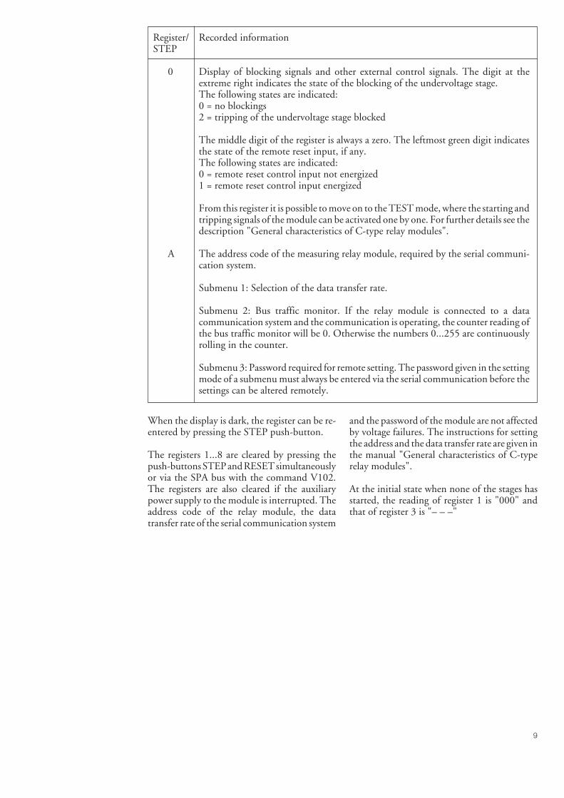
9
Register/ Recorded informationSTEP
0 Display of blocking signals and other external control signals. The digit at theextreme right indicates the state of the blocking of the undervoltage stage.The following states are indicated:0 = no blockings2 = tripping of the undervoltage stage blocked
The middle digit of the register is always a zero. The leftmost green digit indicatesthe state of the remote reset input, if any.The following states are indicated:0 = remote reset control input not energized1 = remote reset control input energized
From this register it is possible to move on to the TEST mode, where the starting andtripping signals of the module can be activated one by one. For further details see thedescription "General characteristics of C-type relay modules".
A The address code of the measuring relay module, required by the serial communi-cation system.
Submenu 1: Selection of the data transfer rate.
Submenu 2: Bus traffic monitor. If the relay module is connected to a datacommunication system and the communication is operating, the counter reading ofthe bus traffic monitor will be 0. Otherwise the numbers 0...255 are continuouslyrolling in the counter.
Submenu 3: Password required for remote setting. The password given in the settingmode of a submenu must always be entered via the serial communication before thesettings can be altered remotely.
When the display is dark, the register can be re-entered by pressing the STEP push-button.
The registers 1...8 are cleared by pressing thepush-buttons STEP and RESET simultaneouslyor via the SPA bus with the command V102.The registers are also cleared if the auxiliarypower supply to the module is interrupted. Theaddress code of the relay module, the datatransfer rate of the serial communication system
and the password of the module are not affectedby voltage failures. The instructions for settingthe address and the data transfer rate are given inthe manual "General characteristics of C-typerelay modules".
At the initial state when none of the stages hasstarted, the reading of register 1 is "000" andthat of register 3 is "– – –"

10
Menu chart
Display off. Normal state
21
Remotely setvalue t< x p4
Set operate time t< of stage U< 21
Checksum of switchgroup SG1
Remotely setpercentage p4
1
Set start voltage U<
Set operate time t> or time multiplier k of stage U>
SUBMENUSTEP FORWARD 1 sSTEP BACKWARD 0,5 s
MAIN MENU SUBMENU
STEP 0,5 s RESET 1 s
1
2
Max. voltage measured during the last start of U>1
Voltage U12 measured
Voltage U23 measured
Voltage U31 measured
Set start voltage U>
2 Remotely setchecksum1 Remotely set
checksum 3 Checksum of switchgroup SG2
2
Remotely setvalue U< x p3
Remotely setvalue U> x p1
Remotely setpercentage p3
Remotely setpercentage p2
Remotely setpercentage p1
Max. voltage measured after reset2
3
Min. voltage measured after reset
5
4
Min. voltage measured during the last start of U<
Number of starts of overvoltage stage
Remotely setvalue t> x p2
Incomingblockings0
A
0 000
1
SS1 TS1 TS2IRF SS2
2 3
= parameter that can be set in the setting mode
6
Duration of the latest start event of stage U>
8
7
Number of starts of undervoltage stage
Duration of the latest start event of stage U<
STEP
BACKWARD
.5s
STEP FORWARD
1s
MAIN MENU
Relay module address code
Data transfer rate (Bd)
Bus communication monitor 0 ... 255
Password
4 Checksum of switchgroup SG3
Fig. 4. Main menus and submenus of the combined overvoltage and undervoltage relay moduleSPCU 3C14.
The procedure for entering a submenu or a set-ting mode and configuring the module is de-
scribed in detail in "General characteristics ofC type relay modules".

11
Voltage/timecharacteristic(Modified 99-10)
At inverse time characteristic the operate timeof the overvoltage stage will be shorter thegreater the deviation from the setting value.
The operation of the U> stage is based on inversetime characteristic, when the selector switchSG1/3 on the front panel is in position 1. Therelationship between time and voltage at inversetime characteristic can be expressed as follows:
t = + c (b x - 0.5)
where t = operate time [s]k> = time multiplierU = measured voltage [V]U> = set start voltage [V]a = constant 480b = constant 32c = constant 0.035p = constant
At an IDMT mode of operation the recording ofthe tripping time of the overvoltage stage doesnot start until the voltage exceeds the settingvalue by 6%. The operating time accuracy statedin the technical data applies when the voltageexceeds the setting value by 10%. The overvoltagestage includes two characteristics with differentinversities. The characteristic is selected withthe programming switch SG1/4. The degree ofinversity is determined by the factor p as follows:
Characteristic p (constant)
A 2B 3
k> x a
1000
100
1 0
1
0,1
0,011,1 1,2 1,3 1,4 1,5 U/U>
0,05
0,2
0,4
0,71,0
k>
t / s
1,0
Fig. 5. Characteristic curve set A of overvoltage stage U>.
U - U>U>
p

12
0,050,20,40,71,0
k>
U/U>1,51,41,31,21,11,00,01
0,1
1
1 0
100
1000
t / s
Fig. 6. Characteristic curve set B of overvoltage stage U>.
Technical data Overvoltage stage U>Start voltage U> 0.8...1.6 x UnStart time 0.1 s or 30 sOperate time at definite time mode of operation 0.05...1.00 s, 0.5...10.0 s or 5...100 sTime multiplier k> at inverse time characteristic 0.05...1.00Reset time, typically 60 msDrop-off/pick-up ratio, typically 0.97Operate time accuracy at definite timemode of operation and start time accuracy ± 2% of set value or ± 25 msOperate time accuracy at inverse time characteristic ± 25 ms or the inaccuracy appearing
when the measured voltage varies ± 3%Operation accuracy ± 3% of set value
Undervoltage stage U<Start voltage U< 0.4...1.2 x UnStart time 0.1 s or 30 sOperate time at definite time characteristic 1...12 s or 10...120 sReset time, typically 60 msDrop-off/pick-up ratio, typically 1.03Operate time accuracy and start time accuracy ± 2% of set value or ± 25 msOperation accuracy ± 3% of set value

13
Serialcommunicationparameters
Event codes
The substation level control data communica-tor is able to read, over the SPA serial bus, theevent data of the module, e.g. starting andtripping, from the over-/undervoltage relaymodule SPCU 3C14. Event information calledfor are printed out in the format: time (ss.sss)and event code. The event codes of the moduleare E1...E8, E50 and E51. Furthermore, thesubstation level control data communicator isable to form event codes relating to e.g. the datacommunication.
The codes E1...E8 and the events represented bythese can be included in or excluded from theevent reporting by writing, over the SPA bus, aso called event mask (V155) to the module. Theevent mask is a binary number coded to adecimal number. The event codes E1...E8 are
represented by the numbers 1, 2, 4...128. Theevent mask is formed by multiplying abovenumbers either by 0 (event not included inreporting) or 1 (event included in reporting)and adding up the numbers received (comparecalculation of checksum).
The event mask may have a value in the range0...255. The default value of the over-/under-voltage relay module SPCU 3C14 is 85, whichmeans that all startings and trippings are in-cluded in the reporting, but not the resetting.The codes E50...E54 and the events representedby these cannot be excluded from the reporting.
Event codes for over-/undervoltage relay mod-ule SPCU 3C14:
Code Event Weighting Defaultcoefficient setting
E1 Starting of overvoltage stage U> 1 1E2 Starting of overvoltage stage U> reset 2 0E3 Tripping of overvoltage stage U> 4 1E4 Tripping of overvoltage stage U> reset 8 0E5 Starting of undervoltage stage U< 16 1E6 Starting of undervoltage stage U< reset 32 0E7 Tripping of undervoltage stage U< 64 1E8 Tripping of undervoltage stage U< reset 128 0
Default value of event mask V155 85
E50 Restart of microprocessor * -E51 Overflow of event register * -E52 Temporary interruption in data communication * -E53 No response from the relay module over the data
communication bus * -E54 The module responds again over the data
communication bus * -
0 not included in event reporting1 included in event reporting* no code number, always included in event reporting- cannot be set
NOTE!In the SPACOM system the event codes E52...E54 are generated by the station level controldata communicator, e.g. type SRIO 1000M.

14
Data to betransferred overthe serial bus(Modified 99-12)
In addition to the event code data transfer, theinput data (I data), output data (O data), set-ting values (S), memorized data (V data) andsome other data can be read from the relay
module over the serial communication bus.Further, part of the data can be changed overthe SPA bus by separate commands. All datainformation is available in channel 0.
Data Code Data Valuesdirect.
Measured voltage U12 I1 R 0...9.99 x UnMeasured voltage U23 I2 R 0...9.99 x UnMeasured voltage U31 I3 R 0...9.99 x UnBlocking of tripping of under- I4 R 0 = no blockingvoltage stage 1 = tripping of stage U<
blocked
Starting of overvoltage stage U> O1 R 0 = U> stage not started1 = U> stage started
Tripping of overvoltage stage U> O2 R 0 = U> stage not tripped1 = U> stage tripped
Starting of undervoltage stage U< O3 R 0 = U< stage not started1 = U< stage started
Tripping of undervoltage stage U< O4 R 0 = U< stage not tripped1 = U< stage tripped
Activated start value for stage U> S1 R 0.8...1.6 x UnActivated operate time t> or time S2 R 0.05...100 s ormultiplier k for stage U> 0.05...1.00Activated start value for stage U< S3 R 0.4...1.2 x UnActivated operate time for stage U< S4 R 1...120 sActivated checksum of switch- S5 R 0...255group SG1
Start value for stage U>, S11 R 0.8...1.6 x Unset with the setting knobOperate time or time multiplier for S12 R 0.05...100 s orstage U>, set with the setting knob 0.05...1.00Start value for stage U<, S13 R 0.4...1.2 x Unset with the setting knobOperate time for stage U<, S14 R 1...120 sset with the setting knobChecksum of switchgroup SG1 S15 R 0...255(set with the switches)
Remote setting percentage of the S21 R, W 0...999%start value for stage U>Remote setting percentage of S22 R, W 0...999%operate time or time multiplierfor stage U>Remote setting percentage of S23 R, W 0...999%start value for stage U<Remote setting percentage of S24 R, W 0...999%operate time for stage U<Remotely set checksum of S25 R, W 0...255switchgroup SG1

15
Data Code Data Valuesdirect.
Remotely set start value for stage U> S31 R 0.8...1.6 x UnRemotely set operate time or time S32 R 0.05...100 s ormultiplier for stage U> 0.05...1.00Remotely set start value for stage U< S33 R 0.4...1.2 x UnRemotely set operate time for stage U< S34 R 1...120 sRemotely set checksum of S35 R 0...255switchgroup SG1
Max. voltage measured when V1 R 0...9.99 x Unstage U> startedMax. voltage measured after resetting V2 R 0...9.99 x UnMin. voltage measured when V3 R 0...9.99 x Unstage U< startedMin. voltage measured after resetting V4 R 0...9.99 x UnNumber of starts of overvoltage stage V5 R 0...255Number of starts of undervoltage stage V6 R 0...255Duration of the latest start V7 R 0...100%event of stage U>Duration of the latest start V8 R 0...100%event of stage U<
Resetting of output relays and V101 W 1 = output relays and operationoperation indicators indicators resetResetting of output relays, operation V102 W 1 = output relays, operationindicators and erasing of recorded data indicators reset and registerssimultaneously (codes V1…V8) erased
Remote control of settings V150 R, W 0 = setting with knobsS11...S15 activated
1 = remote settingsS31...S35 activated
Event mask word V155 R, W 0...255, see section"Event codes"
Manual reset or self-reset mode of V156 R, W 0…15, see sectionoperation of the LED indicators (SG2) "Selector switches"Programming push-buttons (SG3) V157 R, W 0…1, see section
"Selector switches"
Opening of password for V160 W 1...999remote settingsChanging or closing of password V161 W 0...999for remote settings
Activation of self-supervision function V165 W 1 = self-supervision output isactivated and IRF indicatorturns on in about 5 seconds,whereafter the self-super-vision system and the IRFindicator reset
Internal fault code V169 R 0…255
Data communication address V200 W 1...254of the relay module
Program version V205 R 072_

16
Data Code Data Valuesdirect.
Type designation of the relay module F R SPCU 3C14
Reading of event register L R Time, channel numberand event code
Re-reading of event register B R Time, channel numberand event code
Reading of module status data C R 0 = normal state1 = module been subject
to automatic reset2 = overflow of event register3 = events 1 and 2 together
Resetting of module status data C W 0 = resetting
Time reading or setting T R, W 00.000...59.999 s
R = data to be read from the moduleW = data to be written to the module
The data transfer codes L, B, C and T have beenreserved for the event data transfer between therelay module and the control data communi-cator.
The event register can be read by the L com-mand only once. Should a fault occur, for ex-ample, in the data transfer, it is possible, by us-ing the B command, to re-read the contents ofthe event register once already read by means ofthe L command. When required, the B com-mand can be repeated.
The setting values S1...S5 are the alerted setvalues currently used by the protection relaymodule. These values are set either by remotecontrol or by means of the setting knobs. Thevalues S11...S15 are set with the setting knobsand the selector switches. Variables S21...S25are set as percentage values via remote control.
The settings S21...S25 allow reading or writ-ing. A condition for writing is that the pass-word V160, for remote setting has been opened.The variables S31...S35 contain the remote set-ting values.
When the values of the variables S21...S24 areto be changed, the variables can be given a per-centage factor within the range 0...999. It ispossible to alter a setting value beyond the set-ting ranges specified in the technical data of therelay module. However, the validity of the set-ting values are guaranteed only within the set-ting ranges specified in the technical data.
Activation of the self-supervision function(V165) prevents the relay module from operat-ing as long as the self-supervision output is ac-tivated and the IRF indicator is lit.

17
Fault codes Once the self-supervision system has detected apermanent relay fault, the IRF LED on the frontpanel of the module is lit, and at the same timethe normally operated signal relay of the self-supervision system drops off.
In most fault situations an auto-diagnostic faultcode is shown on the relay display. The faultcode cannot be reset. The fault code consists of
a red digit one (1) and a green code numberthat indicates the fault type. The fault codeshould be recorded and stated when service isordered.
The fault codes of the over-/undervoltage relaymodule SPCU 3C14 are explained in the fol-lowing table:
Fault code Explanation
4 Faulty output relay path or missing output relay card30 Faulty program memory (ROM)50 Faulty working memory (RAM)
195 Too low a value in reference channel with multiplier 1131 Too low a value in reference channel with multiplier 5
67 Too low a value in reference channel with multiplier 25203 Too high a value in reference channel with multiplier 1139 Too high a value in reference channel with multiplier 5
75 Too high a value in reference channel with multiplier 25253 No interruptions from the A/D-converter


SPCR 8C27
RESET
STEP
IRF00
35A
TRIGGED / READY
SPCR 8C27Disturbance recorder
User´s manual and Technical description

2
SPCR 8C27Disturbance recorder
Contents Features .......................................................................................................................... 3Application ..................................................................................................................... 3Description of operation ................................................................................................. 4
Triggering.................................................................................................................. 4Recording .................................................................................................................. 4Recording of maximum and minimum values ........................................................... 4Event register ............................................................................................................. 5Unloading of recordings ............................................................................................ 5Serial port .................................................................................................................. 6
Operating modes ............................................................................................................ 6Start-up ..................................................................................................................... 6Setting mode ............................................................................................................. 6Measuring mode ........................................................................................................ 7Unload mode............................................................................................................. 7
Front panel ..................................................................................................................... 8Indicators........................................................................................................................ 8Menu chart ..................................................................................................................... 9Displayed data .............................................................................................................. 10
Measured data ......................................................................................................... 10Status signals ........................................................................................................... 10Data communication parameters ............................................................................. 10
PC programs................................................................................................................. 11Technical data .............................................................................................................. 12Connection of measuring signals .................................................................................. 13Programming with W_ jumpers or PC poard ............................................................... 13Connection cables ........................................................................................................ 15Event codes ................................................................................................................... 17Short parameter specification ........................................................................................ 18
Programming mode ................................................................................................. 18Instantaneous values ................................................................................................ 18Maximum and minimum values supervision ........................................................... 18Triggering conditions .............................................................................................. 18Periodical triggering ................................................................................................ 18Remote triggering .................................................................................................... 19Recording from triggering ....................................................................................... 19Event reporting........................................................................................................ 19Range selections....................................................................................................... 19Rated values ............................................................................................................. 20Management of recording resources ........................................................................ 20Recorder mode ........................................................................................................ 20Unloading of recordings .......................................................................................... 20Data included into recordings ................................................................................. 21Communication settings.......................................................................................... 21Other parameters ..................................................................................................... 21Setting example ....................................................................................................... 22
Remote transfer data ..................................................................................................... 23Maintenance ................................................................................................................. 27
1MRS 750511-MUM EN
Issued 96-12-02Version A (replaces 34 SPCR 2 EN1)Checked L-W UApproved TK
Data subject to change without notice
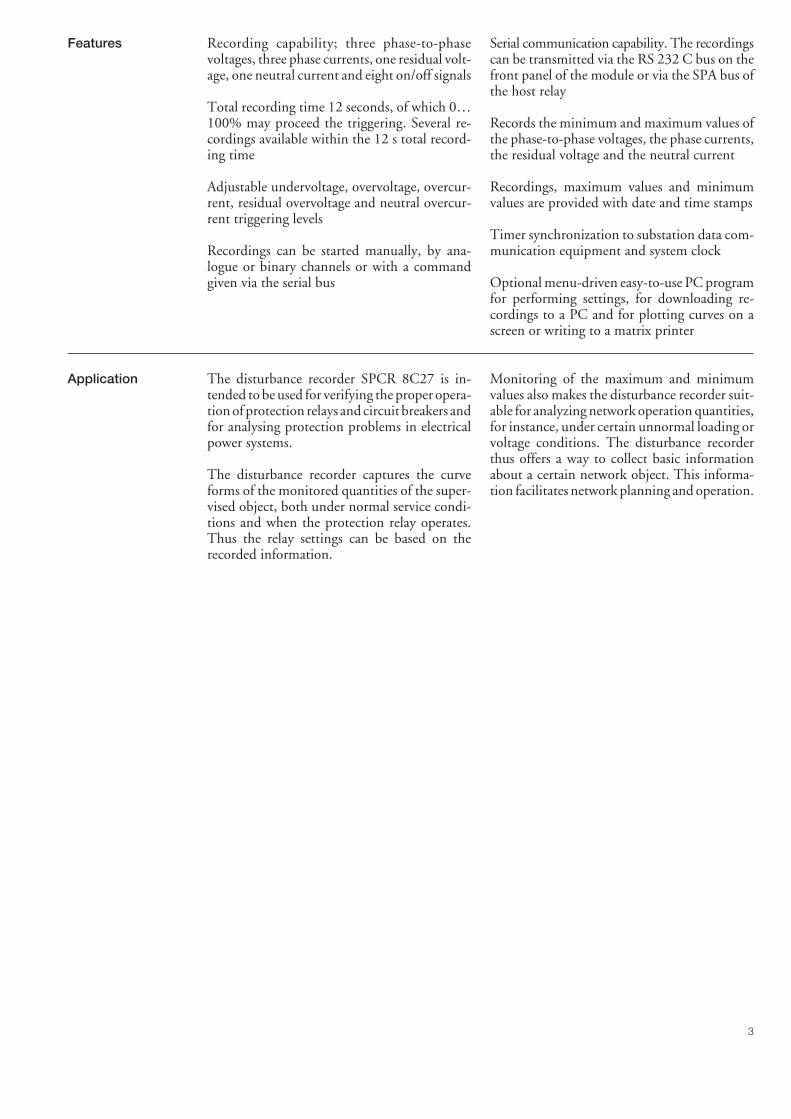
3
Features Recording capability; three phase-to-phasevoltages, three phase currents, one residual volt-age, one neutral current and eight on/off signals
Total recording time 12 seconds, of which 0…100% may proceed the triggering. Several re-cordings available within the 12 s total record-ing time
Adjustable undervoltage, overvoltage, overcur-rent, residual overvoltage and neutral overcur-rent triggering levels
Recordings can be started manually, by ana-logue or binary channels or with a commandgiven via the serial bus
Serial communication capability. The recordingscan be transmitted via the RS 232 C bus on thefront panel of the module or via the SPA bus ofthe host relay
Records the minimum and maximum values ofthe phase-to-phase voltages, the phase currents,the residual voltage and the neutral current
Recordings, maximum values and minimumvalues are provided with date and time stamps
Timer synchronization to substation data com-munication equipment and system clock
Optional menu-driven easy-to-use PC programfor performing settings, for downloading re-cordings to a PC and for plotting curves on ascreen or writing to a matrix printer
Application The disturbance recorder SPCR 8C27 is in-tended to be used for verifying the proper opera-tion of protection relays and circuit breakers andfor analysing protection problems in electricalpower systems.
The disturbance recorder captures the curveforms of the monitored quantities of the super-vised object, both under normal service condi-tions and when the protection relay operates.Thus the relay settings can be based on therecorded information.
Monitoring of the maximum and minimumvalues also makes the disturbance recorder suit-able for analyzing network operation quantities,for instance, under certain unnormal loading orvoltage conditions. The disturbance recorderthus offers a way to collect basic informationabout a certain network object. This informa-tion facilitates network planning and operation.

4
as the protection relay modules. The numberand type of signals to be recorded depend on theprotection relay into which the disturbancerecorder module has been inserted.
Description ofoperation
The disturbance recorder SPCR 8C27 is de-signed to be inserted into any unoccupied relaymodule location of a SPACOM relay case. Thusthe recorder module measures the same signals
Triggering The recorder module may be triggered by phaseovercurrent, undervoltage, overvoltage, residualovervoltage or neutral overcurrent. Further itcan be triggered by on/off input signals, manualcontrol, automatically and periodically or by acommand via the serial bus.
The length of the recording can be selectedseparately for each of the triggering conditions.When the recorder module triggers, a recordingis made and an event message is generatedaccording to the settings made. The recording ofthe parameters and the generation of an eventcan be enabled or disabled separately for eachtriggering condition.
When at least two successive measurementsexceed the preset start value, the triggering con-dition is fulfilled. The undervoltage condition isfulfilled if the value of the two last half cyclesfalls below the preset undervoltage start valueand the undervoltage is not due to a high-speedauto-reclosure going on in the network or anyother circuit-breaker operation. If, during twohalf cycles, the measured voltage falls below
20% of the rated voltage of the relay, the situa-tion is considered to be a circuit-breaker opera-tion and the undervoltage condition is not ful-filled.
The on/off triggering signals are obtained fromthe internal bus of the host relay. The triggeringsignals are formed by start and operate signals ofthe relay modules or by certain external controlsignals. A change of the status of a monitoredsignal triggers the recorder according to the setconfiguration.
The recorder may also be triggered periodicallywhich means that the recorder automaticallymakes a recording at certain time intervals.
The recorder may also be triggered manuallywith the push-buttons on the front panel.
The parameters defining the triggering condi-tions are set via the SPA port of the host relay orvia the RS 232 C port on the front panel of therecorder module.
Recording When the triggering conditions are fulfilled, arecording is made the length of which is max. 12seconds when all channels are used. 0…100% ofthe recording may precede the triggering. Therecording memory is divided into 0.5 secondsblocks. When the shortest possible recordingtime, i.e. 0.5 seconds, is used, there is enoughmemory for 24 consecutive recordings.
The recording memory is used as a buffer stor-age. When the available recording capacity hasbeen exceeded no further recordings are made,
unless the recorder module has been otherwiseconfigured.
The clock and the recording memory of thedisturbance recorder module have been pro-vided with a ten years battery back-up to main-tain information over an auxiliary voltage out-age.
The sampling rate for each recording channel is500 Hz.
Recording of maxi-mum and minimumvalues
The module records the maximum and mini-mum values of the measured phase-to-phasevoltages and the associated time stamps. In thesame way the module records the max. values ofthe phase currents and the associated time stamps.Further, the module records the maximum valueof the residual voltage and the maximum valueof the neutral current, and their associated timestamps. For status signals the time of the laststatus change is recorded. For analog signals the
recorded value and time change once a newmaximum or minimum value is detected.
The recording of the maximum value is basedon instantaneous values and therefore possiblespikes and the dc component of the measuredsignal appear in the recording. The recordedmaximum and minimum values can be read viathe RS 232 C port or the SPA bus.

5
and any event register overflow situation arealso recorded as events. The register also holdsdate and time stamps of the recorded events.
the serial buses or manually by means of thepush-buttons on the front panel.
Printer
SUBSTATION
Printer
NETWORK CONTROL CENTRE
SPACOM Series protection relay with disturbance recorder type SPCR 8C27
Incoming measuring, blocking and status signals
PC
SUBSTATIONSPACOM Series protection relay with disturbance recorder type SPCR 8C27
Incoming measuring, blocking and status signals
Modem
Publictelephone network
Modem
PC
Incoming measuring, blocking and status signals
SUBSTATION
PrinterPCRS 232C
SPA bus
a) b)
c)
SPACOM Series protection relay with disturbance recorder type SPCR 8C27
Fig. 1. Connection of the disturbance recorder SPCR 8C27 to its environment.a) Direct connection to a PC via the RS 232 C port on the front panel.b) Connection to a PC in the control room via the RS 232 C port on the front panel
and a modem.c) Connection to a local substation PC via the SPA bus.
Event register The event register is a log-book containing a listof the events generated. The events, which are tobe recorded are selected separately in an eventlog mask. Any start-up of the recorder module
Unloading ofrecordings
The recordings can be unloaded via the serialbuses. The recordings can be erased, even beforethey have been unloaded, with a command via

6
An available optional menu-driven PC programfacilitates setting of the module and downloadingand plotting of the records. The program fea-tures versatile possibilities for plotting the re-corded signals. An ordinary matrix writer can beused as a hard copy output device.
The PC support program incorporates featuresfacilitating the use of the program and makingit easy to change and update recorder param-eters. The recorder parameters and the plotparameters can be recorded in a file, a featurethat facilitates work that may occur repeatedly.
Following both a warm start-up and a cold start-up the recorder performs a display test by switch-ing on the digits from zero to nine in eachelement of the display. The numbers are dis-played five times.
The module always performs a cold start-upwhen the STEP and RESET push-buttons arepressed during start-up.
After the start-up the recorder enters the meas-uring mode and the display turns dark. In thismode the measuring signals and the communi-cation parameters of the module can be scannedand set by means of the STEP and RESET push-buttons, in the same way as the SPC type relaymodules are set.
the recorder responds to commands coming viathe SPA bus.
If a device providing a DSR handshaking signalhas been connected to the RS port of the re-corder module, the recorder automaticallychanges for communication via RS-bus. Therecorder module cannot receive messages fromboth buses at the same time.
An optional menu-driven PC program consid-erably facilitates the setting procedure. The set-tings can also be saved on a floppy disk for lateruse.
The push-buttons on the front panel of themodule can only be used for setting the datacommunication parameters. In the setting modethe recorder module performs no measurements.
Serial port The RS 232 C port on the front panel of themodule and the SPA-bus is used for unloadingrecordings, for setting module parameters andfor an extended use of the module.
The serial port on the front panel is intended tobe used for the connection of a data communi-cation modem, or if the distance is short, for theconnection of an IBM compatible PC.
When the module recordings are unloaded intoa PC the data can be processed later. A modemconnection allows the recordings to be un-loaded via a telephone line to the control roomor any other place.
Operating modes
Start-up
When the auxiliary supply has been connectedthe recorder module can be started in two ways,that is by performing a warm start-up or a coldstart-up.
Normally the event recorder performs a warmstart-up. But if the module memory contentshave been lost because of a supply failure, themodule perfoms a cold start-up, which meansthat the the memory will be initialized withdefault values. At a cold start-up the moduleloses any earlier set values and any recordedinformation, if any.
At a cold start-up the leftmost red display ele-ment initially indicates "-" and the rightmostgreen display element shows a number withinthe range 01…15 as long as the module isstarting up.
Setting mode In the setting mode e.g. the triggering condi-tions are specified for the module. The settingsare made via the SPA bus or via the RS 232 Cport. The setting mode is entered with thecommand V17:1 via the serial bus. A flashingindication "- - - -" on the display indicates thatthe recorder module is in the setting mode. Exitfrom the setting mode is obtained with com-mand V17:0.
The module performs no measurements as longas it is in the setting mode. Therefore, it isimportant to leave the setting mode when thesetting procedure has been finished. The displaycannot be scanned in the setting mode.
When the settings have been made, the PCconnected to the RS 232 C port can be movedto another place. If no modem or PC is con-nected to the RS 232 C port on the front panel,

7
until the history has been completely collected,the history part of the recording would be inac-curate.
Normally the operation indicator of the re-corder is dark. When the module makes a re-cording, the operation indicator turns green.When the recording has been finished, the op-eration indicator turns red. Then the module isstill in the measuring mode. If there is an oldrecording in the memory and the module istriggered again, the indicator is lit with both redand green colour.
The contents of the recording memory, therecorded maximum and minimum values, thedate and time information of the recordingsremain in the memory. However, all informa-tion is lost at a cold start-up.
Measuring mode The recorder module is normally in the measur-ing mode. It enters the measuring mode afterstart-up. The module also automatically entersthe measuring mode, when an output deviceconnected to the RS 232 C port is disconnected.
In the measuring mode the recorder measuresthe input signals, monitors the triggering condi-tions and records data. Data, that is the curveforms of the supervised signals are constantlyrecorded into the history memory of the re-corder. As the module triggers, a specified partof the history recording preceding the triggeringis moved into the recording memory and thepost-triggering recording starts.
When the measuring mode is left the historymemory is erased. After the module has beenswitched over into the measuring mode a newhistory is collected. Should the module triggers
Each line of measured data (= one measuredvalue per signal) forms a separate message. Theunloading of a recording ends with an emptymessage. The unloading can be interrupted bytransmitting any message to the recorder.
At a 1200 baud data transfer rate via the RS 232C port, unloading of a one second recordingtakes about 5 minutes. The same data transfertakes about 40 s at a data transfer rate of 9600baud.
The unloading via the SPA bus is made in the socalled SPA unloading mode (V20). Then therecords are unloaded piece by piece by readingone line of measured data at a time. Thus theSPA bus is occupied for unloading recordingsonly for short periods at a time.
In the SPA-unloading mode the recorder meas-ures the input signals but performs no record-ings.
The same command as with the RS 232 C portis used for removing the oldest recording.
The optional PC program makes it possible toread the recordings, display them grafically on amonitor or to produce hard copy outputs. Withthe PC program signals can be expanded andshifted in time and value to show all informationin detail. It is also possible to save the records ona floppy disk.
Unload mode In the unload mode the curve forms of thesignals stored in the recording memory are trans-mitted from the recorder via the SPA bus or theRS 232 C port. This mode is indicated by aflashing "U" in the rightmost element of thedisplay.
The recordings are always unloaded startingfrom the oldest one. Access to the youngerrecordings is admitted only after removing theolder ones.
The recordings are unloaded and erased in thesetting mode using the commands V15, "un-loading of the oldest recording" or V16, "eras-ing of the oldest recording", which are transmit-ted over the RS bus. In this state the recorderperforms no measurement or recording func-tions.
When data is unloaded via the RS 232 C portthe information is transmitted in the form ofmessages of max. 80 characters each, accordingto the SPA protocol. The entire recording istransmitted after command V15, i.e. "unload-ing of the oldest recording". Proceeding themeasured data a few lines of information aboutthe recording is transmitted, such as an outputinformation heading, a code of the event caus-ing triggering, input headings, rated values etc.The sample values are related to the peak valueof the sinusoidal signal, that is the peak value ofthe nominal sinusoidal signal equals 1. RMSvalues can be calculated from individual samplevalues by multiplying the values by the factor√2.

8
tion associated with the operation states of themodule is also displayed on the front panel.
Front panel From the front panel it is possible to check themeasured values and to do certain settings re-quired for the data communication. Informa-
SPCR 8C27
RESET
STEP
IRF
0035
A
TRIGGED / READY
Simplified device symbol
Self-supervision alarm indicator
Digital display for measured values
Display STEP push-button
9-pin female D-type connector ofthe RS 232 C port
RESET push-button
Operation indicator
Module type designation
Fig. 2. Front panel of the disturbance recorder SPCR 8C27.
When the self-supervision system detects aninternal fault an automatic self-recovery attemptis made. If the self-recovery attempt provesunsuccessful a renewed start-up or a cold start-up should be performed.
The following fault codes may appear on thedisplay on detection of an internal fault:
Fault code Explanation
1 Random Access Memory(RAM) fault
2 Program memory(EPROM) fault
3 Stack overflow4 Parameter memory
(EEPROM) fault
Indicators The state of the recorder is shown by the LEDindicator in the right-hand bottom corner of thefront panel. The operation indicator shows thatthe module has triggered (Trig) and is making orhas already made a recording. Under normalservice conditions the indicator is dark indicat-ing that the recorder is prepared for recording(Ready) and that there are no recordings in thememory.
The red light will remain on until all the record-ings have been read and/or erased. The red lightdoes not prevent the recording function.
The self-supervision alarm indicator IRF in theupper right-hand corner of the front panel is litwhen the self-supervision system has detected apermanent hardware or software fault in therecorder module. In most fault situations anauto-diagnostic fault code appears on the dis-play. The fault code consists of a red number "1"and a green code number.
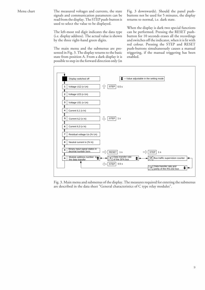
9
Fig. 3 downwards). Should the panel push-buttons not be used for 5 minutes, the displayreturns to normal, i.e. dark state.
When the display is dark two special functionscan be performed. Pressing the RESET push-button for 10 seconds erases all the recordingsand switches off the indicator, when it is lit withred colour. Pressing the STEP and RESETpush-buttons simultaneously causes a manualtriggering, if the manual triggering has beenenabled.
Menu chart The measured voltages and currents, the statesignals and communication parameters can beread from the display. The STEP push-button isused to select the value to be displayed.
The left-most red digit indicates the data type(i.e. display address). The actual value is shownby the three right-hand green digits.
The main menu and the submenus are pre-sented in Fig. 3. The display returns to the basicstate from position A. From a dark display it ispossible to step in the forward direction only (in
Display switched off
Data transfer rate of the SPA bus
1Module address number inthe data transferA
9 Binary input signal states in decimal number form
Current IL3 (x In)
Current IL1 (x In)
Current IL2 (x In)
Residual voltage Uo (% Un)7
8 Neutral current Io (% In)
5
6
4
Voltage U23 (x Un)2
Voltage U31 (x Un)3
1 Voltage U12 (x Un)
Bus traffic supervision counter2
Data transfer rate and parity of the RS-232 bus3
= Value adjustable in the setting mode
STEP 0.5 s
STEP 1 s
RESET 1 s
STEP
STEP 1 s
0.5 s
Fig. 3. Main menu and submenus of the display. The measures required for entering the submenusare described in the data sheet "General characteristics of C type relay modules".

10
age value function forms the measured value tobe displayed. This method yields a more stabledisplay but, consequently, the display does notfully respond to rapid changes.
The measured data are presented as relativevalues of the set rated values interpreted fromthe maximum value that has occurred during ahalf cycle. For sinusoidal input signals the dis-play ratio factor also corresponds to the relativeRMS value of the input signal.
The phase-to-phase voltages and the phase cur-rents are presented as multiples of the ratedvoltage (x Un) or the rated current (x In). Themeasured values of the residual voltage channeland the neutral current channel are presented aspercentages of the rated voltage Un and the ratedcurrent In.
The numbers representing the different statusdata are shown in the table below.
Status data Number representingthe status data
Status data 1 1Status data 2 2Status data 3 4Status data 4 8Status data 5 16Status data 6 32Status data 7 64Status data 8 128
Displayed data
Measured data
There are eight analog input signals: for threephase-to-phase voltages, three main currents,one residual voltage and one neutral current.The data are displayed in the display addresslocations 1…8, see Fig. 3.
When the recorder module is plugged into athree-phase differential relay for power trans-formers all the six phase currents, that is three onthe high-voltage side and three on the low-voltage side of the transformer can be measured.This can be done after the phase-to-phase volt-age inputs have been changed from voltageinputs to current inputs by means of jumpers onthe PC board of the recorder module. (See W 3,4, 5 in Fig. 5, 6 and 7).
The measured data are not updated at the samerate as the measurements would allow. An aver-
Status signals The eight status signals are coded to decimalnumbers within the range 0…255 and pre-sented on the display in the address location 9.The number is formed by adding the values,representing the different states, in the same wayas the checksum of switchgroup SG1 of the relaymodules is calculated. The same coding is usedfor the status data read over the serial communi-cation.
By splitting the displayed number into the ele-ments which form the number, the relevantstatus data are retrieved. The coding method isbased on the principle of presenting positiveintegers in binary form. This method makes itpossible to use a calculator capable of decimal-binary conversions for retrieving the states.
The modules’ address code, which is the sameon the SPA bus and the RS 232 bus, is shown inaddress A. The address code may have a valuewithin the range 001…899. The default codeafter a cold start-up is 001. The address code ofthe recorder module is set in the setting mode,one number at a time, starting from the rightmostdigit.
The data transfer rate for the SPA bus, the bustraffic monitor value and the data transfer rateand the parity of the RS 232 C bus are to befound in the submenues of address location A.
The data transfer rate of the SPA bus, which isconnected to the D-type connector on the rearplate, is expressed in thousand bits/second (kBd).Alternative values are 0.3 kBd, 1.2 kBd, 2.4 kBd,4.8 kBd and 9.6 kBd. Even parity is always usedand shown as a number 2 in front of the datatransfer rate value.
The bus traffic monitor shows whether therecorder module receives messages via the com-munication buses or not. The counter runs from0 to 255, one step a second. Any messagereceived resets the counter. If the counter valueremains 0, it indicates that messages are arrivingat a rate higher than once a second.
The parity of the RS 232 C bus is presented asa number in front of its data transfer rate value.The number may be 0 (parity none) or 2 (parityeven). The number of data bits is 8. The re-corder does not approve of odd parity.
After a cold start-up the RS 232 C bus has noparity and the data transfer rate is 1.2 kBd. Theother available baud rates are the same as thoseof the SPA bus. The data transfer rate is set in thesame way as for the SPA bus.
Data communica-tion parameters

11
PC programs Two PC programs for MS-DOS or PC-DOSbased microcomputers have been developed forthe use together with the disturbance recorder.The programs facilitate parametrization of themodule and unloading of recordings either viathe RS 232 C port on the front panel or via theSPA bus. The PC programs are not part of therecorder delivery but they are available on re-quest as optional products. The SPCR EVALtype designation includes the English languageversions of both programs and a 3 m cable whichconnects the recorder module to a PC.
The first program is a easy-to-use communica-tion program for operating the recorder mod-ule. The program runs using SPA protocolcommands recognised by the recorder module.The program also transmits and receives mes-sages based on the SPA protocol.
The second menu-driven program facilitatesparameter setting and downloading of record-ings. In addition, this program allows the curveforms unloaded from the recorder module to bepresented on the PC screen, written down onpaper or recorded on a disk.
The current versions of the two programs re-quire a microcomputer with the following fea-tures:
- microcomputer IBM/PC, IBM/XT, IBM/ATor compatible
- at least 384 kB conventional RAM- at least 1 MB XMS or free hard disk space- display drivers:
- EGA, VGA or SVGA colour display- Hercules single-colour display- Toshiba T2100/T3100 plasma display- AT & T single-colour display
(Olivetti single-colour display)- MikroMikko 3 single-colour display- Wyse GDA single-colour display
- operating system MS-DOS 2.11 or laterversion.
Should a printer be used, it has to be a 9-pinIBM compatible or a 24-pin Epson LQ-2500compatible version. Most of the 24-pin printerson the market are compatible with the EpsonLQ-2500 printer.
MS-DOS is a registered trade mark of Microsoft Corp. IBM is aregistered trade mark of International Business Machines Corp. PC-DOS, IBM/PC, IBM/XT, IBM/AT are registered trade marks ofInternational Business Machines Corp.
Fig. 4. Example of the curve display made by SPCR EVAL software.

12
Technical data Number of input channels 8 analogue inputs8 on/off inputs
Sampling frequency/channel 500 Hz (default)A/D converter 11 bitTime difference between samplingof adjacent input channels 250 µs (default)Recording capacity- 1 MB SRAM Max. 24 recordings
Max. 224 blocks- 4 MB SRAM (option) Max. 26 recordings
Max. 992 blocks(1 block = 1 recorded channel x 0.5 s)
Analogue channelsMeasuring ranges- Phase-to-phase voltages;
analogue inputs 1…3 0.0…2.5 x Un or 0.0…21 x Un- Phase currents;
analogue inputs 4…6 0.0…2 x In or 0.0…20 x In- Residual voltage;
analogue input 7 0.0…102% Un- Neutral current,
analogue input 8 0.0…20% In or 0.0…102% InMeasuring accuracy of individual samples ±2%(value >0.2 x range, f = 0…60 Hz)
Triggering limits:- Undervoltage condition;
for analogue inputs 1…3 0.2…overvoltage condition x Un- Overvoltage condition;
for analogue inputs 1…3 Undervoltage condition……21 x Un
- Overcurrent condition;for analogue inputs 4…6 0.0…20.4 x In
- Residual voltage condition;for analogue input 7 0.0…102% Un
- Neutral current condition;for analogue input 8 0.0…102% In
- Status signal inputs Triggering on rising or falling edgeClock resolution 5 msClock accuracy <1 min/monthOptional PC program SPCR EVAL (3 1/2" disk)Ambient temperature -10…+55°CStorage temperature -40…+70°C
EMC-TestsFast transients IEC 255-22-4 2 kV, 5/50 nsElectrostatic discharge IEC 255-22-2, class III- air discharge 8 kV- contact discharge 6 kV

13
same as those used in the instruction manualsfor the SPACOM relays.
Input Terminal Name of signal in the SPACOM systemnumber
Analogue input 1 4a(8a) Phase-to-phase voltage U12 (or IL1')Analogue input 2 5a(8c) Phase-to-phase voltage U23 (or IL2')Analogue input 3 6a(9a) Phase-to-phase voltage U31 (or IL3')Analogue input 4 4c Phase current IL1Analogue input 5 5c Phase current IL2Analogue input 6 6c Phase current IL3Analogue input 7 7a Residual voltage U0Analogue input 8 7c Neutral current I0Status signal inputs
Status data 1 9c Autoreclose initiation via AR2Status data 2 10a Autoreclose initiation via AR3Status data 3 10c Autoreclose initiation via AR1Status data 4 11a Autoreclose blocking and interruption via ARINHStatus data 5 11c *) Circuit-breaker position via CBPOSStatus data 6 12aStatus data 7 12c *) Blocking of circuit-breaker closing via CBINHStatus data 8 13a Selection of basic angle for E/F relays via BACTRLStatus data 5x 13cStatus data 6x 14a *) Blocking signal BS1Status data 7x 14cStatus data 8x 15a *) Blocking signal BS2
Connection ofmeasuring signals
The pins of the PCB connector of the SPCR8C27 module have been designated accordingto the table below. The signal names are the
5x…8x alternatives to status datas 5…8. Pro-gramming is made with resistors R49 (a, b, c, d)
and R50 (a, b, c, d), see fig. 6 and 7. *) Factoryprogramming.
Programming withW_ jumpers or PCpoard
Fig. 5. Programming using the W_ jumpers.
EPROM size = 64 kByte = 512 kBit(factory default setting)
W1
W2
W3
W4
W5
EPROM size = 32 kByte = 256 kBit
Alarm from self diagnostics i.e. IRF-signal is disabled to output relay(factory default setting)
Alarm from self diagnostics i.e. IRF-signal is enabled to output relay
Channel 1 = U12 phase-to-phase voltage (e.g. in relay SPAU 330)(factory default setting)
Channel 1 = IL1' secondary current (e.g. in relay SPAD 330)
Channel 2 = U23 phase-to-phase voltage (e.g. in relay SPAU 330)(factory default setting)
Channel 2 = IL2' secondary current (e.g. in relay SPAD 330)
Channel 3 = U31 phase-to-phase voltage (e.g. in relay SPAU 330)(factory default setting)
Channel 3 = IL3' secondary current (e.g. in relay SPAD 330)

14
Fig. 6. Signal block diagram of the SPCR 8C27 recorder module.
W3
W4
W5
EPROMPLD
CPUW2
W1
D9S
abcdR50
abcdR49
R9
EPROM
RAM
Battery/clock circuitDS 1216E (Dallas)
Battery circuitDS 1213D (Dallas)
Fig. 7. PC board lay-out showing the location of jumpers and resistors.
MUX
~~~~~~
DISPLAY
SPA BUS
RS 232
Binarychannels
W5U31
IL3'
W4U23
IL2'
W3U12
IL1'
IL1
IL2
IL3
Uo
Io
IRFW2
abcd
R49
R50abcd
R49 a, R49 b, R49 c, R49 d, R50 a, R50 b, R50 c, R50 d = programming resistors
123456785x6x7x8x

15
SPCR 8C27
9-pin Signal and directionconnector
1 DCD<---2 RxD <---3 TxD --->4 DTR/+11 V--->5 GND6 DSR <---7 RTS --->8 CTS <---9 No connection
IBM PC-AT or corresp. IBM PC or correspond. Modem
9-pin Signal and 25-pin Signal and 25-pin Signal andconnector direction connector direction connector direction
- - -2 - - -> RxD 3 - - -> RxD 2 - - -> TxD3 <- - - TxD 2 <- - - TxD 3 <- - - RxD8 - - -> CTS 5 - - -> CTS 4 - - -> RTS7 <- - - RTS 4 <- - - RTS 5 <- - - CTS1, 4 <- - - DCD, DTR 8, 20 <- - - DCD, DTR 6 <- - - DSR5 GND 7 GND 7 GND6 <- - - DSR 6 <- - - DSR 8 <- - - DCD6 - - -> DSR 6 - - -> DSR 20 - - -> DTR
A 9-pin male D-type connector is always usedon the disturbance recorder side. When thedisturbance recorder is connected to an IBMPC-AT or a compatible device, a 9-pin femaleD-type connector is normally used on the PCside. Correspondingly, a 25-pin femaleconnectoris used for an IBM PC or a compatible device,and a 25-pin male connector for connecting thecable to a modem.
Examples of cables to be used between a modemand a PC are given in the table below. The leftcolumn refers to the connection of the cable inthe cable on the modem side and the othercolumns to the connection of the cable on theoutput device side. The pins not mentioned areto be left unconnected.
Modem IBM PC-AT or corresp. IBM PC or corresp.
25-pin Signal and 9-pin Signal and 25-pin Signal andconnector direction connector direction connector direction
1 - -2 TxD <- - - 3 <- - - TxD 2 <- - - TxD3 RxD - - -> 2 - - -> RxD 3 - - -> RxD4 RTS <- - - 7 <- - - RTS 4 <- - - RTS5 CTS - - -> 8 - - -> CTS 5 - - -> CTS6 DSR - - -> 6 - - -> DSR 6 - - -> DSR7 GND 5 GND 7 GND8 DCD - - -> 1 - - -> DCD 8 - - -> DCD
20 DTR <- - - 6 <- - - DSR 20 <- - - DTR
Connection cables Cables suited for connecting the disturbancerecorder SPCR 8C27 to the output device, viathe RS 232 C port of the front panel, are listedin the table below. The left column refers to theconnection of the cable connector on the distur-bance recorder side and the other columns to theconnection of the output device or modem sideconnector. The pins not mentioned in the tableare left unconnected.

16
A 25-pin male D-type connector is always usedin the cable end towards the modem, whereas a9-pin female D-type connector is normally usedfor the cable end connecting an IBM PC-AT ora compatible device. A 25-pin female D-typeconnector is used for the cable end connecting
an IBM PC or a compatible device.
A cable type SPA-ZP17A_ is available for con-nection of the recorder module to a PC providedwith a 9-pin D-type connector.
1
23
4
5
6
78
9
1
23
4
5
6
78
9
Blue
Red
Yellow
Black
RxD
TxD
DTR
GND
RTS
CTS
RxD
TxD
DSR
GND
DCD
CTS
9-pins D-connector/malerecorder end
9-pins D-connector/femalePC-End
Fig. 8. Connection cable type SPA-ZP17A_.

17
event mask is formed by multiplying the abovenumbers either by 0 (event not included in thereporting) or 1 (event included) and adding upthe numbers received (cf. the calculation of thechecksum).
The event mask may take a value in the range0…65535. The default value of the disturbancerecorder is 65535, which means that all theevents that have caused triggering are includedin the event reporting. The events E52…E54are included only in the data communicationover the SPA bus. These codes are formed by thesubstation control data communicator and can-not be excluded from the event reporting.
The event codes of the disturbance recorderSPCR 8C27 are as follows:
Event codes The event monitoring functions of the distur-bance recorder memorize the code of each eventand the time at which the event occurred. Thetriggerings of the recorder are regarded as events.On request the module prints out the event dataover the SPA bus in the format: time (ss.sss, a socalled short clock time) and event code. Theevent data transmitted over an RS 232 C busincludes the event code and a long-clock time(yy-mm-dd hh.mm; ss.sss).
The event codes of the module are E1…E16 andE50 and E51. The codes E1…E16 and the eventsrepresented by these can be included in orexcluded from the event reporting by writing anevent mask (V155) to the module. The eventmask is a binary number coded to a decimalnumber. The event codes E1…E16 are repre-sented by the numbers 1, 2, 4…32768. The
Code Event Weighting Defaultcoefficient setting
E1 Triggering on overcurrent (IL1, IL2 or IL3) 1 1E2 Triggering on residual voltage (U0) 2 1E3 Triggering on neutral current (I0) 4 1E4 Triggering on overvoltage (U12, U23 or U31) 8 1E5 Triggering on undervoltage (U12, U23 or U31) 16 1E6 Triggering on change of signal 1 status 32 1E7 Triggering on change of signal 2 status 64 1E8 Triggering on change of signal 3 status 128 1E9 Triggering on change of signal 4 status 256 1E10 Triggering on change of signal 5 status 512 1E11 Triggering on change of signal 6 status 1024 1E12 Triggering on change of signal 7 status 2048 1E13 Triggering on change of signal 8 status 4096 1E14 Manual triggering or triggering on external control signal 8192 1E15 Triggering on remote command (V21) 16384 1E16 Automatic periodical triggering (V22, V23) 32768 1
Defalt value of event mask V155 65535
E50 Unacknowledged reset (status word = 1) * -E51 Overflow of event register (status word = 2) * -E52 Temporary interruption in data communication * -E53 No response from the relay module over the data
communication bus * -E54 The relay module responds again over the data
communication bus * -
0 not included in event reporting1 included in event reporting* no code number, always included in event reporting- cannot be set
Note!In the SPACOM system the event codesE52…E54 are generated by the substation datacommunicator.

18
Short parameterspecification
The parameters readable and settable via serialcommunication can be grouped in the follow-ing way:
mode is entered and exit using parameter V17,see chapter "Setting mode" in the manual, (page5).
Programming mode The parameters can be read while the recorder isin the measuring mode, but the parameters arechiefly set in the setting mode. The settting
values dating to the moment of measurementand scaled to the rated values In and Un. Thescaling factors can be altered using parametersM36 and M37, see passage "Rated values".
Instantaneous values The signals measured by the recorder module,i.e. the currents, voltages and status signals, areread using parameters I1…I8 and I10. Thevalues obtained from the recorder module are
its peak value. Only one value can be written forthe different phase-to-phase voltages and thephase currents. When a new value is written, allthe old values are reset. Writing always resets thetime. If the search for a maximum and mini-mum value is to be started all over, the desiredstart level must be written to the variable.
The status channel contains only the time recordof the last change. According to parameters S1and S10, writing of any permitted character tovariables V7…V14 will erase the time record.
Maximum andminimum valuessupervision
The recorder module continuously searches forand records the max. and min. values of themonitored signals. The limit values can be readusing parameters V2…V14. The values are scaledto the corresponding rated values.
A value or a value and a time tag are obtained onreading. The three phase-to-phase voltages andthe three phase currents refer to the same meas-uring moment, i.e. for voltages when one of thevoltages reaches its maximum or minimum valueor for currents when one of the currents reaches
The triggering conditions for the status signalsare given as binary coded values, all eight signalswith one parameter as described in chapter"Displayed data/Status signals" of the manual,(page 9).
Triggering from a status signal can be obtainedfrom the rising edge or the falling edge of a statussignal as defined with parameter S10. Parametervalue 0 = triggering on falling edge and param-eter value 1 = triggering on rising edge. Thetriggering conditions for all the eight channels1, 2, 3,…8 are given in the same parameter oneby one after each other. The setting 00001111,for instance, means that the channels 1…4 aretriggered on a falling edge and the channels5…8 on a rising edge.
Triggeringconditions
For the recorder module to make a recording,the following conditions must be fulfilled:
- the recorder module is in the measuring mode- enough unused recording memory is available- a triggering condition is fulfilled- a recording from the particular triggering con-
dition is permitted, see variable V24- the length of the recording from the particular
triggering condition has been set greater than0 blocks using parameter M27.
The triggering conditions are set with param-eters S1…S6 and S10.
The triggering conditions for the analog signalsare defined directly as current and voltage val-ues.
re-established and the backwards counting startsagain. The counter value can be read fromparameter V23. The counter value can be al-tered by writing a new value to parameter V23.
If the value of parameter V22 is 0, no periodicaltriggering is obtained.
Periodicaltriggering
The recorder module can be set to automaticallyexecute triggerings at certain time intervals, i.e.a so called periodical triggering. The requiredtime interval in seconds is written to variableV22. When a new value is written to parameterV22, the timer starts counting seconds from theset value backwards. When the counter reacheszero, a triggering occures, the counter setting is

19
Remote triggering The recorder module can be triggered via theserial bus using parameter V21. The parameter
is first given the value 0 which then is changedto 1.
Ex, where A denotes the history length in blocks,B denotes the length of the recording in blocks,counted from the triggering moment and Ex isthe code of the concerned triggering. For in-stance, by writing 1 5 E1 the recorder module isprogrammed to make a six block recordingincluding one history block on triggering onovercurrent (E1). Further it must be noted thatthe values A and B together must not exceed themaximum recording capacity of the recordermodule.
If a recording has been made from one of thetriggerings E1…E5 of the analog channels, anew triggering of the same channel is preventedfor a time interval defined by parameter M35.However, any other triggering than the onewhich started the last recording, starts an imme-diate recording.
Recording fromtriggering
The triggerings from which a recording is per-mitted are selected with parameter V24. Theparameter is set in the same way as para-meterV155, the setting of which is described inchapter "Event codes" (page 17).
The length of the recording is defined withparameter M27, separately for each triggering.Note! The history part of each recording has thesame length for all triggerings. If attempts aremade to set history parts of different lengths, therecorder module, however, equalizes the historyparts for the different triggerings. The length ofthe history part is determined by the last settingvalue. When parameter M27 is read the lengthsof all triggerings are obtained at the same time,but when new values are written the values mustbe given separately for each triggering. Themessage to be written shall have the form: A B
command. If, for instance, a fault arises in thecommunication system, the contents of theevent register once read with the L commandcan be re-read by using the B command. Ifrequired, the B command can be repeated.
Event reporting The triggerings which are to be included in theevent reporting are defined with parameter V155,i.e. the event mask parameter. This parameterdoes not affect the recording procedure. Theevent register can be read once with the L
phases of the voltage channels and the currentchannels cannot be given different measuringranges. If the recorder module is going to beplugged into a differential relay the voltagechannels are transformed into current channelsby means of jumpers, in which case Ux deter-mines the measuring range for the low-voltageside phase currents.
Range selections Each analogue quantity, except for the residualvoltage, have two selectable measuring ranges,which are selected with parameter M34. If thesignal to be measured exceeds the measuringrange, the measured signal will be cut. The formof the parameter is Ix Io Ux, where Ix denotesthe ranges of the phase current channels, Io therange of the residual current channel and Ux theranges of the voltage channels. The different
M34 Phase currents (Ix) I0 current (I0) Phase-to-phase voltages (Ux)
0 0 0 0…20 x In 0…20% In 0…2.5 x Un0 0 1 0…20 x In 0…20% In 0…21 x Un0 1 0 0…20 x In 0…102% In 0…2.5 x Un0 1 1 0…20 x In 0…102% In 0…21 x Un1 0 0 0…2 x In 0…20% In 0…2.5 x Un1 0 1 0…2 x In 0…20% In 0…21 x Un1 1 0 0…2 x In 0…102% In 0…2.5 x Un1 1 1 0…2 x In 0…102% In 0…21 x Un

20
corresponding range of M34 = 1). The valuescorrespond to the value of the A/D converter ata 100% input signal level. By changing thesevalues only the scaling of the measuring range isaffected and changes are not to be recommended.
Rated values The rated values used for scaling the recordermodule can be altered with parameters M36 andM37. The values of parameter M36 function onthe normal ranges (the corresponding range ofM34 = 0) and M37 on the alternative ranges (the
ing headers. Each recording needs one record-ing header. CHA denotes the number of freechannel headers. Each recording requires asmany channel headers as the number of moni-tored channels (all channels = 9 pcs). BLOdenotes the number of recording blocks. Thenumber of recording blocks needed per channelis defined with parameter M27.
Note! The recording resources needed for col-lecting history parts are not seen in parameterM32, unless the recorder module is in the set-ting mode. Therefore the recorder module maybe able to perform a recording, although therecording resource seems to be zero.
Managementof recordingresources
The default setting of the recorder module per-mits no further recordings, when the capacity ofthe recording memory has been fully used. Withparameter M38 the recorder module can, how-ever, be given a mode of function, where therecorder module automatically creates the nec-essary amount of free recording capacity byerasing the oldest recordings from the memory.
The currently available amount of free record-ing memory of the recorder module can be readwith parameter M32.
Both parameters have the form: REC CHABLO, where REC is the number of free record-
show the number of recordings still in thememory.
With parameter V25 the state of the recordermodule can be read. The V25 parameter showswhether the recorder module is in the measuringmode, whether the recorder module has suc-ceeded in collecting the necessary number ofhistory parts and whether the recorder modulecurrently is making a recording. The collection ofhistory recordings is explained in chapter "Meas-uring mode" (page 6).
Recorder mode Parameter C can be used for determining, if therecorder module has performed an unreset startor if the event register is full (overflow). Bothstates are also seen in the reading of the eventbuffer. The states are reset by writing 0 to theparameter.
The number of recordings made by the recordermodule (cumulative counter) and the numberof recordings currently in the memory can beread with parameter V1. Any value written tothe parameter makes the cumulative counter
The recordings are maintained in the memoryof the recorder module after they have beenunloaded. The recordings are erased with para-meter V16.
Unloading ofrecordings
The recordings are unloaded via the bus inter-face on the front panel using parameters V20and V15. The recordings are unloaded via theSPA bus using parameters V20, M28…M31.

21
Further, among other things the followingsettable data are part of the recording:
- Main heading of the recording (M21)- headings of the measuring channels (M22)- primary values of the measured quantities
(M23…M25)
These values are not utilized by the recordermodule and they do not affect the function ofthe recorder module in any other way than thatthey are included in the recordings. ParametersM21 and M22 define the heading of the record-ing and the headings of the various channels(quantities). When parameter M22 is read allthe channel headings are obtained at once, butwhen the headings are written the headings ofthe channels are preferrably written one by one.The write message should be composed of thechannel number and the channel heading. Ex-ample: 4 L1, which means that channel 4 willobtain the heading L1. The characters < > : / nor &must not be included in the headings written byparameters M21 and M22. The primary valuesof the corresponding quantities are written withparameters M23…M25.
Data includedinto recordings
The monitored quantities of the recorder mod-ule which are to be included in the recording aredetermined with parameter M33. The defaultsetting is that all the measured quantities (chan-nels) are included in the recording. Those chan-nels which are not used (no measurement) canbe excluded from the recording with parameterM33. Any excluded channel will obtain a fixedvalue of zero, which will increase the recordingcapacity of the module. If, for instance, only halfof the channels are included in the recording therecording capacity is doubled. The parametervalue is written in binary form as follows:
Channel Weightingcoefficient
1 (U12) 12 (U23) 23 (U31) 44 (I1) 85 (I2) 166 (I3) 327 (U0) 648 (I0) 1289 (8 status channels) 256
front panel port and the SPA port). ParameterV201 affects only the settings of the communi-cation port used for setting, while the other portremains unchanged.
Communicationsettings
The communication address of the recordermodule is given with V200 and the data transferrate with parameter V201. The same parametersare used for both communication ports (the
Parameter F can be used for reading the typedesignation and parameter V205 for reading theprogram version indicator of the recorder mod-ule.
Parameters T and D are used for setting the dateand time of the recorder module.
Other parameters Parameter V102 can be used for restarting therecorder module.
Parameter V165 can be used for testing the self-supervision function (IRF) of the recorder mod-ule.

22
Setting example The recorder module has been inserted into thefeeder terminal type SPAC 531 C.
Parameter Parameter specification
S1 7 Status signals 1…3 are used for triggeringV24 224 Recording permitted from triggering of status signals 1…3
(32 + 64 + 128 = 224)M21 K5 plant Main heading of recording (cubicle name)M22 4 I1 Channel heading of recordingM22 5 I2 Channel heading of recordingM22 6 I3 Channel heading of recordingM22 7 U0 Channel heading of recordingM22 8 I0 Channel heading of recordingM23 20 Primary value of voltage (kV)M24 1000 Primary value of current (A)M25 70 Primary value of earth-fault current (A)M27 1 4 E6 Length of recordingM27 1 4 E7 Length of recordingM27 1 1 E8 Length of recordingM33 504 Selection of channels (the voltage channels are excluded)M34 0 1 0 For channel I0 the bigger range is selectedM35 10 Dead time between triggeringsM38 2 12 60 Old recordings are deleated so that capacity is always available for
two new recordings
In the above example the recorder module hasbeen inserted into a feeder terminal type SPAC531 C. On operation the protection relay mod-ules initiate autoreclose functions via the start-ing signals AR1…AR3. By programming therecorder module to be triggered via these signals(status signals 1…3) a recording is obtained anytime the relay operates.
The lengths of the recordings triggered with theAR2 and AR3 signals are set to be 2.5 s of which0.5 s is history. This time normally reaches overone high-speed autoreclosure. The length of therecording triggered with the AR1 signal is shorter
(0.5 s + 0.5 s) because the AR1 signal is (nor-mally) obtained from the high-set stage of theovercurrent protection module.
The phase-to-phase voltages are not measured,which increased the available recording capacitywith approx. 30%. Thus the total recordingcapacity will be 37 blocks, that is max. 7 record-ings. Further only the last five recordings arekept in the recording memory, as selected withparameter M38. The recorder module alwaysprovides recording capacity for two recordings,i.e. 2 x 6 channels x 5 blocks = 60 blocks.

23
All information cannot be read or written overboth buses. The table shows the bus over whichreading or writing is permitted.
All data are available on the SPA protocol basedchannel 0, except for the unloading of record-ings over the SPA bus.
Data Code Data Bus Valuesdirect.
Measured value of the U12 voltage I1 R SPA/RS 0…2.558 x Un or0…21.3 x Un
Measured value of the U23 voltage I2 R SPA/RS 0…2.558 x Un or0…21.3 x Un
Measured value of the U31 voltage I3 R SPA/RS 0…2.558 x Un or0…21.3 x Un
Measured value of the IL1 current I4 R SPA/RS 0…20.46 x In or0…2.046 x In
Measured value of the IL2 current I5 R SPA/RS 0…20.46 x In or0…2.046 x In
Measured value of the IL3 current I6 R SPA/RS 0…20.46 x In or0…2.046 x In
Measured value of the U0 voltage I7 R SPA/RS 0…102.3% x UnMeasured value of the I0 current I8 R SPA/RS 0…20.46% x In or
0…102.3% In
States of the binary inputs, I10 R SPA/RS 0…255binary coded decimals
Binary input condition mask, S1 R, W SPA/RS 0…255. Determines thebinary coded decimals channels which are to
be used for triggering.Default value: 255
Overvoltage condition S2 R, W SPA/RS [S3]…999.999 x UnDefault value: 1.20 x UnS2 and S3 cannot becross-set
Undervoltage condition S3 R, W SPA/RS 0.201…[S2] x UnDefault value: 0.80 x Un
Overcurrent condition S4 R, W SPA/RS 0…999.9 x InDefault value 2.00 x In
Residual overvoltage condition S5 R, W SPA/RS 0…999.9% x UnDefault value: 20.0 % x Un
Neutral overcurrent condition S6 R, W SPA/RS 0…999.9% x InDefault value: 5.0% x In
Triggering of the binary input S10 R, W SPA/RS XXXXXXXX, where the Xchannels letters stand for the binary
input channels 1…8.X = 1 trig. on rising edgeX = 0 trig. on falling edgeDefault value: 11111111
Total number of recordings V1 R, X SPA/RS AB, whereA = total number of
recordings madeB = number of recordings
currently in memoryWriting any value makesA = B in the device
Remote transferdata
In addition to the event codes it is possible toread over the SPA or RS 232 C bus all the inputdata (I data), setting values (S data), recordeddata (V data) and some other data of the distur-bance recorder. Further, part of the informationcan be altered with commands given over theSPA bus.

24
Data Code Data Bus Valuesdirect.
Supervision of the maximum value V2 R, X SPA/RS U12, U23, U31 date timeof the phase-to-phase voltage Voltage notation x Un
Date: yy-mm-ddTime: hh.mm;ss.sss
Supervision of the minimum value V3 R, X SPA/RS U12, U23, U31 date timeof the phase-to-phase voltage Also see command V2Supervision of the maximum V4 R, X SPA/RS IL1, IL2, IL3 date timevalue of the phase current Current notation x In
Also see command V2Supervision of the maximum V5 R, X SPA/RS U0 date timevalue of the residual voltage Voltage notation % Un
Also see command V2Supervision of the maximum V6 R, X SPA/RS I0 date timevalue of the neutral current Current notation x In
Also see command V2Time of activation of binary input V7… R, X SPA/RS Date timechannels 1…8 V14 Writing clears date and
timeUnloading of oldest recording V15 R RS Writes the oldest
recording to theRS 232 C port
Erasing of oldest recording V16 W SPA/RS When V16 changes from0 to 1, the oldest recordingis deleted
Selection of setting mode V17 X SPA/RS 0 = exit setting mode1 = enter setting mode
Selection of unloading mode V20 R, X SPA 0 = no unloading via theSPA bus
1 = unloading via the SPAbus using commandsM28…M31.
After initiation of unloadingthe variables M29 andM30 are reset
Remote triggering V21 R, X SPA/RS Change from 0 to 1causes triggering viaevent E15
Setting of time interval for V22 R, X SPA/RS 0…40 000 000 secondsperiodical recording 0 = triggering disabledTimer for the periodical triggering V23 R, X SPA/RS 1…40 000 000 seconds
The timer counts down-wards.
Selection of events that are V24 R, X SPA/RS 0…65535, see chapterto trigger recordings "Event codes"Measurement status V25 R SPA/RS 0…65535
0 = inoperative (not inmeasuring mode)
1 = measuring mode,history collectingnot ready
3 = measuring mode,history collected
5 = currently recording,uncollected history
7 = currently recording

25
Data Code Data Bus Valuesdirect.
Resetting of recorder V102 X SPA/RS 1 = warm start-up2 = cold start-up
Event mask word for event logging V155 R, W SPA/RS 0…65535, see chapter"Event codes"
Activation of self-supervision V165 X SPA/RS 0 = reset of outputoutput (IRF) 1 = activation of output
Recorder module address V200 W SPA/RS 001…899
Data transfer rate V201 W SPA 20.3, 21.2, 22.4, 24.8 or29.6 kBd using 7 databits, even parity and onestop bit. The first figuremeans even parity.
W RS 0.3, 1.2, 2.4, 4.8, 9.6 or19.2 kBd using 8 databits, no parity and onestop bit.
W RS 20.3, 21.2, 22.4, 24.8,29.6 or 219.2 kBd using8 data bits, even parityand one stop bit. The firstfigure means even parity.
Program version code V205 R SPA/RS E.g. NDR110
Main heading of recording M21 R, X SPA/RS Character string; max.64 characters.Warning!Do not use charactersreserved by the SPAprotocol.
Channel headings M22 R, X SPA/RS When read, the channeltitles are sent in a rowseparated by slashes.Max. title length is 6characters.When written, the datafield contains channelnumber and titleseparated by a blank.One title can be set foreach message.
Rated voltage (kV), peak value M23 R, X SPA/RS 0…9999.999Rated current (A), peak value M24 R, X SPA/RS 0…9999.999Rated neutral current (A), M25 R, X SPA/RS 0…9999.999peak value Also see M23
Length of the recordings M27 R, W SPA/RS A B Ex, whereA = history length in blocksB = recording length after
triggering in blocks.Event codes E1…E16

26
Data Code Data Bus Valuesdirect.
Reading of the recording headline M28 R SPA Ex B C date time, whereof the oldest recording Ex = letter E and event
numberB = history length [blocks]C =rec. length [blocks]date = yy-mm-ddtime = hh.min;ss.sssAlso see command V20.
Block index for unloading of M29 R, X SPA 1…blocks in recordingrecording via the SPA busLine index for unloading of M30 R, X SPA 1…250 data sample linesrecording via the SPA busReading of recording line M31 R SPA Example:
>1 R1/10 M31:xx1/10 = channels 1 to 10Channels 1…8 = analoguesignalsChannel 9 = emptyChannel 10 = 8 pcsbinary signals
Available free recording memory M32 R SPA/RS REC CHA BLOSelection of channels to be M33 R, W SPA/RS 0…511, used as bitmaskmonitoredGain setting for the analogue channels M34 R, W SPA/RS Ixgain Iogain Uxgain
Three blank separatedboolean numbers (0/1).Default value 0 0 0
Dead time between triggerings M35 R,X SPA/RS 0…1000 secondsof the same triggering source Default setting: 120 sRated value factor for the M36 R,W SPA/RS 8 blank separatedanalogue channels numbers at range
1…65535.Channel order in the vectoris U12, U23, U31, IL1, IL2,IL3, U0 and I0
Alternative rated value factor M37 R,W SPA/RS See M36 commandfor the analogue channelsRecording resource reserver M38 R,W SPA/RS REC CHA BLO
This command is used toset the minimum amountof recording memory thatthe recorder tries to main-tain available.
Sampling rate of recording M40 R SPA/RS Rate of each channelcommandSee M31 command
Type designation of F R SPA/RS SPCR 8C27the recorder module
Short time setting T X SPA/RS 00.000…59.999 sOnly to transmissionaddress 900

27
Data Code Data Bus Valuesdirect.
Long time reading or setting T R, X SPA/RS date = yy-mm-ddtime = hh.min;ss.sssTo the recorder’s ownaddress
Long time setting D X SPA/RS Equal to variable TTo transmission address900 of all modules
Reading of event register L R SPA/RS Time (short/long),channel number andevent codeExample:34.630 0E7/10.780 0E1This is in long format whenreading via the RS bus(date included)
Re-reading of event register B R SPA/RS See previous code (L)
Reading of module status data C R SPA/RS 0 = normal state1 = module has restarted2 = overflow of event
register3 = events 1and 2 together
Resetting of module status data C X SPA/RS 0 = resetting
Explanation of the direction codes:R = data to be read from the moduleW = data to be written in the setting mode (V17 = 1)X = data to be written (does not require setting mode)
Maintenance The batteries are mounted on IC sockets.
Clock back-up battery type Dallas DS 1216 EData memory battery type Dallas DS 1213 D
The recorder module is provided with batterysupport for the clock circuit and the datamemory. The calculated life time for the batter-ies is 10 years but proper operation of therecorder module is guaranteed if the batteriesare replaced every fifth year.


L1 IRF
>I
L2I L3II
1309
[ ]sk
>t0.5
0.05 1.0
13
2.5
0.5
0.04 1.0
0.5
1.5
2.5
STEP
RESET
SG1
0 1
1234567820
STEP
>>I
nI>I
nI>>I
>>t [ ]s
>I >>I
SPCJ 3C3
B
Indicators for measured values
Setting knob 1with indicator
Stage 1
Setting knob 2with indicator
Setting knob 3with indicator
Stage 2
Setting knob 4with indicator
Self-supervision alarm indicator(Internal Relay Fault)
Display, 1 + 3 digits
Step push-button (STEP)
Programming switches SG1
Switchgroup indicator
Reset push-button (RESET)
Start/operation indicators
General characteristics ofC-type relay modules
User´s manual and Technical description

2
General characteristics ofC-type relay modules
Contents Push-buttons .................................................................................................................. 2Programming switches SG1 ............................................................................................ 2Setting knobs .................................................................................................................. 3Display ........................................................................................................................... 3
Display main menu ................................................................................................... 3Display submenu ....................................................................................................... 4Setting mode ............................................................................................................. 4Example: Operation in setting mode ......................................................................... 5Stored information .................................................................................................... 6Trip-test mode........................................................................................................... 7Example: Trip-test function ...................................................................................... 8
Operation indicators ....................................................................................................... 9Fault codes ...................................................................................................................... 9
Push-buttons The front panel of the relay module containstwo push-buttons. The STEP button is used forstepping forward in the display and the RESETbutton for resetting the red indicators. Addi-tionally, the push-buttons are used for certain
settings, e.g. for setting the address of the relaymodule and the data transfer rate for the serialcommunication when the modules are used inrelay packages provided with this quality. (Seesection Display).
Programmingswitches SG1
Part of the settings and the selections of theoperating characteristics for the relay modulesin various applications are made with the pro-gramming switches SG1 on the front panel. Theindicator of the switchgroup glows when the
checksum of the switchgroup is shown on thedisplay. The checksum can be used for checkingthat the switches are properly set. Fig. 2 gives anexample of calculating the checksum.
Fig. 2. Example of calculating the checksum of programming switchgroup SG1.
When the checksum calculated according to theexample is equal to the checksum indicated onthe display of the relay module, the switches areproperly set.
The function of the programming switches ofthe individual measuring relay modules is speci-fied in the description of the module concerned.
1MRS 750328-MUM EN
Issued 96-02-19Version A (replaces 34 SPC 2 EN1)Checked L-W UApproved TK
Data subject to change without notice

3
Setting knobs Most of the operating values and operatingtimes are set by means of the setting knobs onthe front panel of the relay module. Each settingknob has its own (LED) indicator which glowswhen the concerned setting value is shown onthe display.
If a setting knob is turned while the display isshowing another measured or set value, thevalue being set automatically appears on thedisplay. Simultaneously, the indicator for theconcerned setting starts glowing.
In addition to the settings made with the settingknobs, most modules allow so called remotesetting. This means that the settings made bymeans of the setting knobs of the module andthe checksum of the programming switchgroupmay be altered through an instruction over theserial communication bus. Remote setting ispossible if the password in the register A isknown, and the remote settings are not acti-vated, i.e. parameter V150=0. The circumstancethat the remote settings are activated is shownwith a flashing light of the indicator of thesetting knob, the value of which currently isbeing displayed.
Display The measured and set values as well as the datarecorded are shown on the display of the meas-uring relay module. The display consists of fourdigits. The three digits (green) to the rightindicate the measured, set or stored value andthe digit at the extreme left (red) the number ofthe register. The measured or set value displayedis indicated by a yellow LED indicator. Thenumber of the register glows only when a storedvalue is displayed.
When the auxiliary voltage is connected to ameasuring relay module, the module initiallytests the display by stepping through the digits1...9 for about 15 seconds. When the test isfinished the display turns dark. The testing canbe interrupted by pressing the STEP button.The protective functions of the module areoperative throughout the testing.
Display main menu All the data required during normal operatingconditions are accessible from the main menuwhich presents the measured values in real-time,the normal setting knob settings as well as themost important memorized data.
The data to be shown in the main menu areselected to the display in a certain sequence bymeans of the STEP button. When pressing theSTEP button for about one second, the displaymoves forward in the display sequence. Whenpressing it for about 0.5 seconds, the displaymoves backwards in the display sequence.
From a dark display only forward movement ispossible. When keeping the STEP button de-pressed, the display is continuously moving inforward direction stopping for a while at thedark point.
Unless the display is switched off by stepping tothe dark point, it remains activated for about 5minutes from the last pressing of the STEPbutton and then goes out.

4
Display submenu Less important values and values not very oftenset are displayed in the submenus. The numberof submenus varies with different relay moduletypes. The submenus are presented in the de-scription of the concerned module.
A submenu is entered from the main menu bypressing the RESET button for about one sec-ond. When the button thereafter is released, thered digit (STEP) of the display starts flashing,indicating that one is in a submenu. Going fromone submenu to another or back to the mainmenu follows the same principle as when mov-ing from the main menu display to another; the
display moves forward when pressing the STEPbutton for one second and backward whenpressing it for 0.5 seconds. The return to themain menu has taken place when the red STEPdisplay turns dark.
When entering a submenu from a measured orset value indicated by a LED indicator, theindicator remains glowing and the address win-dow (STEP) of the display starts flashing. Aflashing address window when no LED indica-tor is lit indicates that the submenu of a registerhas been entered.
Fig. 3. Example of the main and submenus for the settings of the overcurrent relay module SPCJ3C3. The settings made with the setting knobs are in the main menu and they are displayed bypressing the STEP button. In addition to the setting knob settings the main menu contains themeasured current values as well as the registers 1…5, as well as 0 and A. The remote settingpercentage and remote setting value are located in the submenus for the settings and are activatedon the display by pressing the RESET button.
Setting mode The registers of the main menu and the submenusalso contain parameters to be set. The settingsare made in the so called setting mode, which isaccessible from the main menu or a submenu bypressing the RESET button, until the digit atthe extreme right starts flashing (about 10 s).The flashing digit is set by means of the STEPbutton. The flashing is moved on from digit todigit by pressing the RESET button.
A set value is stored in the memory by pressingthe push-buttons STEP and RESET simultane-ously. In practice the RESET button must be
pressed slightly in excess of the STEP button.Return from the setting mode to the main menuor submenu is possible by pressing (for about 10s) the RESET button until the green digits onthe display stop flashing. If the module is left inthe setting mode, it will return automatically tothe start condition after about 5 minutes.
The values to be set in the setting mode are forinstance the address code of the relay moduleand the data transfer rate for the serial commu-nication. Further the percentage values for theremote settings can be changed.

5
Example 1: Function in the setting mode. Manual setting ofthe address code of a relay module and the datatransfer rate for the serial communication. Theinitial value for the address code is 146.
a)Press push-button STEP until register address Aappears on the display.
b)Press the RESET button for about 10 s until theright most digit starts flashing.
c)Press the STEP button repeatedly to set the digitto the value desired.
d)Press the RESET button to make the middle ofthe green digits flash.
e)Set the middle address digit by means of theSTEP button.
f)Press the RESET button to make the left mostgreen digit flash.
g)Set the digit by means of the STEP button.
h)Store the set address number in the memory ofthe relay module by pressing the RESET andSTEP button simultaneously. At the momentthe information enters the memory, the threegreen dashes flash in the display, i.e. A—.
i)Leave the setting mode by pressing the RESETbutton for about 10 s, until the display stopsflashing.
j)Then enter submenu 1 of register A by pressingthe RESET button for approx. one second. Theregister address A is then replaced by a flashing1. This submenu is used for setting the datatransfer rate of the serial communication.
k)The data transfer rate for the serial communica-tion is set and stored in the same way as theaddress, see sections b...i, except that the con-tinuously glowing register address has been re-placed by a flashing 1.
l)After storing the data transfer rate for the serialcommunication you may return to the mainmenu of register A by pressing the STEP buttonfor about 0.5 second.

6
Stored information The parameter values measured at the momentwhen a fault occurs are recorded in the registers,in some modules also the setting values. Therecorded data, except for some setting param-eters, are set to zero by pressing the push-buttons STEP and RESET simul-taneously.The data in normal registers are erased if theauxiliary voltage supply to the relay is disrupted,only the set values and the number ofautoreclosings are maintained in the registers ata voltage failure.
The number of the registers varies with differentmodule types. The function of the registers areillustrated in the descriptions of the separaterelay modules. Additionally, the system panelcontains a simplified list of the data recorded bythe various relay modules of the relay assembly.
All C-type relay modules are provided with twogeneral registers: register 0 and register A.
Register 0 contains, in coded form, the informa-tion about e.g. external blocking signals andstatus information for the circuit breaker. Thecodes are explained in the descriptions of therelay modules.
Register A contains the address code of the relaymodule as required by the serial communicationsystem. Example 1 on page 4 shows how theaddress code is altered. Submenu 1 of register Acontains the data transfer rate value expressed inkilobaud for the serial communication.
Submenu 2 of register A contains a bus trafficmonitor for the SPACOM system. If the protec-tive relay, which contains the relay module, islinked to a system including the control datacommunicator and the data communicationsystem is operating, the counter reading of themonitor will be zero. Otherwise the digits 1...255are continuously rolling in the monitor.
Submenu 3 contains the password required forchanging the remote settings. The address code,the data transfer rate for the serial communica-tion and the password can be set manually or viathe serial communication bus. For manual set-ting see example 1.
The start value for the address code and thepassword is 001 and that for the data transferrate 9.6 kilobaud.

7
Trip-test mode Register 0 also allows access to the so calledTrip-test function, which allows the outputsignals of the relay module to be activated one byone. If the auxiliary relay module of the protec-tion assembly is in place, the auxiliary relays willbe included in the testing.
When pressing the RESET button for about 10seconds, the three green digits to the right startflashing to indicate that the relay module is intest position. The indicators of the setting knobsindicate by flashing which output signal can beactivated. The required output function is se-lected by pressing the RESET button for about1 second, until the following LED indicatorstarts flashing.
The indicators of the setting knobs refer to thefollowing output signals:Setting knob 1 SS1 Starting of stage 1Setting knob 2 TS1 Tripping of stage 1Setting knob 3 SS2 Starting of stage 2Setting knob 4 TS2 Tripping of stage 2No indication IRF Self-supervision
The selected starting or tripping is activated bysimultaneous pressing of the push-buttons STEPand RESET. The signal remains activated aslong as the two push-buttons are being pressed.
The self-supervision output is activated by press-ing the STEP button once when no setting knobindicator is flashing. The IRF output is acti-vated in about 5 seconds after pressing of theSTEP button, and resets after that. Simultane-ously, the display returns to the main menu andperforms the initial testing indicated by rollingdigits 0...9 in the display several times.
The signals are selected in the order illustrated infig. 4.
REGISTER 0IRF SS1 TS1 SS2 TS2
STEP STEP+RESET
STEP+RESET
STEP+RESET
STEP+RESET
RESET10 s
RESET1 s
RESET1 s
RESET1 s
RESET1 s
RESET1 s
Fig. 4. Sequence order for selecting the output signals in the Trip-test mode.
If e.g. the indicator of the setting knob 2 (secondfrom the top) is flashing, and the push-buttonsSTEP and RESET are being pressed, the signalTS1 (tripping of stage 1) is activated. Return tothe main menu is possible at any stage of the
Trip-test sequence scheme, by pressing theRESET button for about 10 seconds. If themodule is left in the Trip-test mode, it willreturn automatically after approx. 5 minutes.

8
Example 2: Trip-test function. Forced activation of the out-puts is made as follows:
a)Step forward on the display to register 0.
b)Press the RESET button for about 10 secondsuntil the three green digits to the right and theLED indicator of the uppermost setting knobstart flashing.
c)Press the push-buttons RESET and STEP si-multaneously. Then the starting of stage 1 (e.g.the I>-stage of the overcurrent module SPCJ3C3) is activated and, simultaneously, the indi-cator of the stage starts glowing yellow.
d)Press the RESET button for about 1 seconduntil the indicator of the second setting knobstarts flashing.
e)Press the push-buttons RESET and STEP si-multaneously to activate tripping of stage 1 (e.g.the I>-stage of the overcurrent module SPCJ3C3). The indicator of the concerned stagestarts glowing red.
f)Starting and tripping of the second stage isactivated in the same way as stage 1. The indica-tor of the third or fourth setting starts flashing toindicate that the concerned stage has been acti-vated.
g)To activate the self-supervision output step to-wards the test position, where no indicator isflashing. Press the STEP button once. In about5 seconds the red IRF indicator starts glowingand the IRF output is activated. Shortly thereaf-ter the indicator goes out and the output auto-matically resets. At the same time the moduleleaves the test position.
h)It is possible to leave the trip test mode at anystep of the sequence scheme by pressing theRESET button for about 10 seconds until thethree digits to the right stop flashing.

9
Operationindicators
A measuring relay module is provided with twoseparate operating stages, each of which with itsown yellow/red operation indicator on the lowerpart of the front plate of the relay module.
The operation indicator starts glowing yellowwhen the operating stage starts and red when adelayed tripping operates. The functions of thestart and operation indicators are described indetail in the different protection relay modulemanuals.
Fault codes In addition to the protective functions the relaymodule is provided with a self-supervision sys-tem which continuously supervises the functionof the microprocessor, its program executionand the electronics.
When the self-supervision system has detected apermanent fault in the relay module, the redIRF indicator on the panel starts glowing soonafter the fault was discovered. At the same timethe module puts forward a signal to the self-supervision contact of the relay assembly.
In most fault situations a fault code, indicatingthe nature of the fault, appears on the display ofthe module. The fault code, which consists of ared digit (1) and a three digit green code number,cannot be removed from the display by reset-ting. When a fault occurs, the fault code shouldbe recorded and stated when service is ordered.

1MR
S 7
5050
8-M
UM
E
N
ABB OySubstation AutomationP.O.Box 699FIN-65101 VAASAFinlandTel. +358 (0)10 22 11Fax.+358 (0)10 22 41094www.abb.com/substationautomation