sparibs geometry parameterization for wings with … · · 2017-01-26sparibs geometry...
TRANSCRIPT
SpaRibs Geometry Parameterization for Wings with Multiple Sections using Single Design Space
Shuvodeep De1, Mohamed Jrad2, Davide Locatelli3 and Rakesh K. Kapania4
Virginia Polytechnic Institute and State University, Blacksburg, VA, 24061-0203
Myles Baker
M4 Engineering, Inc., Long Beach, California 90807
Chan-gi Pak
NASA Armstrong Flight Research Center, Edwards, California 93523
Abstract:
The SpaRibs topology of an aircraft wing has a significant effect on its structural behavior and stability as well
as the flutter performance. The development of additive manufacturing techniques like Electron Beam Free
Form Fabrication (EBF3) has made it feasible to manufacture aircraft wings with curvilinear spars, ribs
(SpaRibs) and stiffeners. In this article a new global-local optimization framework for wing with multiple
sections using curvilinear SpaRibs is described. A single design space is used to parameterize the SpaRibs
geometry. This method has been implemented using MSC-PATRAN to create a broad range of SpaRibs
topologies using limited number of parameters. It ensures C0 and C1 continuities in SpaRibs geometry at the
junction of two wing sections with airfoil thickness gradient discontinuity as well as mesh continuity between
all structural components. This method is advantageous in complex multi-disciplinary optimization due to its
potential to reduce the number of design variables. For the global-local optimization the local panels are
generated by an algorithm which is totally based on a set algebra on the connectivity matrix data. The great
advantage of this method is that it is completely independent of the coordinates of the nodes of the finite element
model. It is also independent of the order in which the elements are distributed in the FEM. The code is verified
by optimizing of the CRM Baseline model at trim condition at Mach number equal to 0.85 for five different
angle of attack (-2°, 0°,2°,4° and 6°). The final weight of the wing is 19,090.61 lb. This value is comparable to
that obtained by Qiang et al. 6 (19,269 lb)
1 Graduate Research Assistant, Department of Biomedical Engineering and Mechanics 2 Post-Doctoral Fellow, Department of Aerospace and Ocean Engineering 3 Senior Research Scientist, Department of Aerospace and Ocean Engineering 4 Mitchell Professor of Aerospace and Ocean Engineering, Affiliate Professor, Engineering Science and Mechanics,
Associate Fellow AIAA
https://ntrs.nasa.gov/search.jsp?R=20170000460 2018-06-27T21:22:47+00:00Z
I. Introduction
The design and optimization of an aircraft structure is a challenging task which involves many disciplines, each
characterized by its own set of requirements, constraints and objectives. The multi-disciplinary optimization of
structures can be traced back to the work of Schmit 1,2,3 where numerical optimization techniques have been integrated
with finite element analysis. Since 1970, multi-disciplinary design optimization is increasingly gaining popularity in
the aircraft industry, especially due to the exponential increase in computational power. Haftka 4,5,6, Sobieszczanski-
Sobieski 7 and their colleagues performed optimization of aircraft wing considering multiple constraints, such as
strength, flutter velocity and buckling.
Recently, Taminger et al.8 at NASA Langley Research Center developed a novel additive manufacturing
technique known as electron-beam-free-form-fabrication (EBF3), which enables the manufacture of metallic structures
of arbitrary curvature. This new technology was leveraged by Kapania and his group at Virginia Tech 9, 10, 11 for
developing a family of frameworks to optimize the shape of the internal structure of an aircraft wing with curvilinear
stiffening members. Joe et al 12 at M4-Engineering Inc. also developed a set of tools and techniques for modeling and
optimizing the structure of a wing with curvilinear SpaRibs. It has already been proven 13, 14, 15 that curvilinear stiffeners
can improve the buckling resistance of arbitrary shaped panels. Locatelli et al. 11 optimized an aircraft wing structure
using curvilinear spars and ribs (SpaRibs) and showed their potential to minimize the weight of a supersonic civil
transport vehicle. While their studies didn’t take into account the aero-elastic performances, Jutte et al. 16 performed
extensive parametric study using the NASA Common Research Model varying the number, location and curvature of
the stiffening members, i.e. spars, ribs and stiffeners, and demonstrated that configurations characterized by weight
lower than the baseline aircraft and higher flutter speed exist. Mallik et al 17 studied the penalty imposed on the
minimum take-off weight and fuel-consumption due to higher flutter constraint.
The following work is part of the development of the EBF3WingOpt framework intended to represent the
SpaRibs geometry using minimum number of parameters and optimize the structure for a wide range of aircraft wings.
A reduction in the number of design variable reduces the computational cost in the multi-disciplinary optimization
problem.
II. Geometry parameterization and Finite Element modeling
One can define a set of parameters for specifying the topology of each of the ribs and each of the spars.
Although this makes the topology definition very flexible, the main disadvantages are that firstly, the number of design
variables becomes very large which leads to high computational cost of the optimization process and secondly, the
number of spars and the number of ribs cannot change during the optimization. Using the linked-shape approach 11,
SpaRibs can be defined with a small number of parameters. In fact, with this approach a maximum of six parameters
are needed to define a set of curvilinear SpaRibs in each of the wing sections, however their shape is not independent
from each other.
As shown in Figure 1 the curves defining the shape of the SpaRibs are first created in the normalized space
and then transformed to the physical space using MSC-PATRAN geometry generation module. Each of the curves is
created using a third order B-spline. The control points of the set of B-splines in the wing-box lines lie on the same
line segment (known as the control-line). As listed in Table 1, the number of SpaRibs is specified by design variable
P1 while the variables P2 and P3 define the position of the control point line. The start and end points of the control-
line are on two specific edges of the wing-box. Spacing between the start points, the control points and the end points
are computed with a geometric series. The three variables: r1, r2 and r3 are the ratios of first spacing and last spacing
between adjacent points.
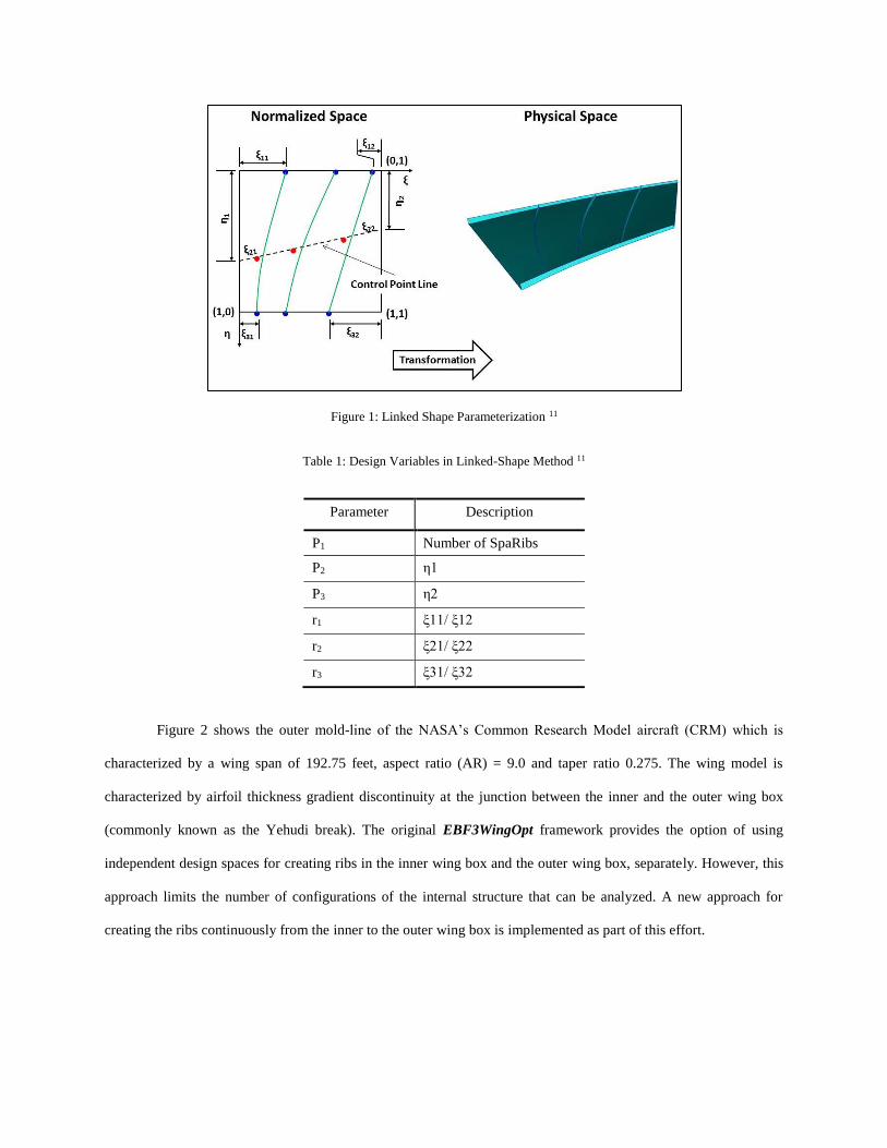
Figure 1: Linked Shape Parameterization 11
Table 1: Design Variables in Linked-Shape Method 11
Parameter Description
P1 Number of SpaRibs
P2 η1
P3 η2
r1 ξ11/ ξ12
r2 ξ21/ ξ22
r3 ξ31/ ξ32
Figure 2 shows the outer mold-line of the NASA’s Common Research Model aircraft (CRM) which is
characterized by a wing span of 192.75 feet, aspect ratio (AR) = 9.0 and taper ratio 0.275. The wing model is
characterized by airfoil thickness gradient discontinuity at the junction between the inner and the outer wing box
(commonly known as the Yehudi break). The original EBF3WingOpt framework provides the option of using
independent design spaces for creating ribs in the inner wing box and the outer wing box, separately. However, this
approach limits the number of configurations of the internal structure that can be analyzed. A new approach for
creating the ribs continuously from the inner to the outer wing box is implemented as part of this effort.
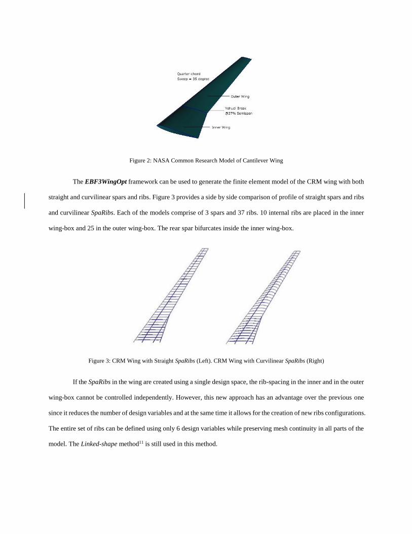
Figure 2: NASA Common Research Model of Cantilever Wing
The EBF3WingOpt framework can be used to generate the finite element model of the CRM wing with both
straight and curvilinear spars and ribs. Figure 3 provides a side by side comparison of profile of straight spars and ribs
and curvilinear SpaRibs. Each of the models comprise of 3 spars and 37 ribs. 10 internal ribs are placed in the inner
wing-box and 25 in the outer wing-box. The rear spar bifurcates inside the inner wing-box.
Figure 3: CRM Wing with Straight SpaRibs (Left). CRM Wing with Curvilinear SpaRibs (Right)
If the SpaRibs in the wing are created using a single design space, the rib-spacing in the inner and in the outer
wing-box cannot be controlled independently. However, this new approach has an advantage over the previous one
since it reduces the number of design variables and at the same time it allows for the creation of new ribs configurations.
The entire set of ribs can be defined using only 6 design variables while preserving mesh continuity in all parts of the
model. The Linked-shape method11 is still used in this method.
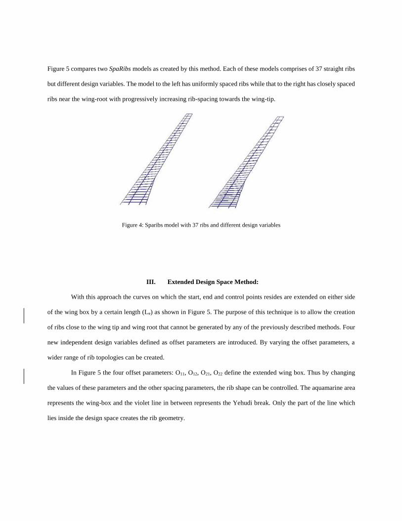
Figure 5 compares two SpaRibs models as created by this method. Each of these models comprises of 37 straight ribs
but different design variables. The model to the left has uniformly spaced ribs while that to the right has closely spaced
ribs near the wing-root with progressively increasing rib-spacing towards the wing-tip.
Figure 4: Sparibs model with 37 ribs and different design variables
III. Extended Design Space Method:
With this approach the curves on which the start, end and control points resides are extended on either side
of the wing box by a certain length (Le) as shown in Figure 5. The purpose of this technique is to allow the creation
of ribs close to the wing tip and wing root that cannot be generated by any of the previously described methods. Four
new independent design variables defined as offset parameters are introduced. By varying the offset parameters, a
wider range of rib topologies can be created.
In Figure 5 the four offset parameters: O11, O12, O21, O22 define the extended wing box. Thus by changing
the values of these parameters and the other spacing parameters, the rib shape can be controlled. The aquamarine area
represents the wing-box and the violet line in between represents the Yehudi break. Only the part of the line which
lies inside the design space creates the rib geometry.
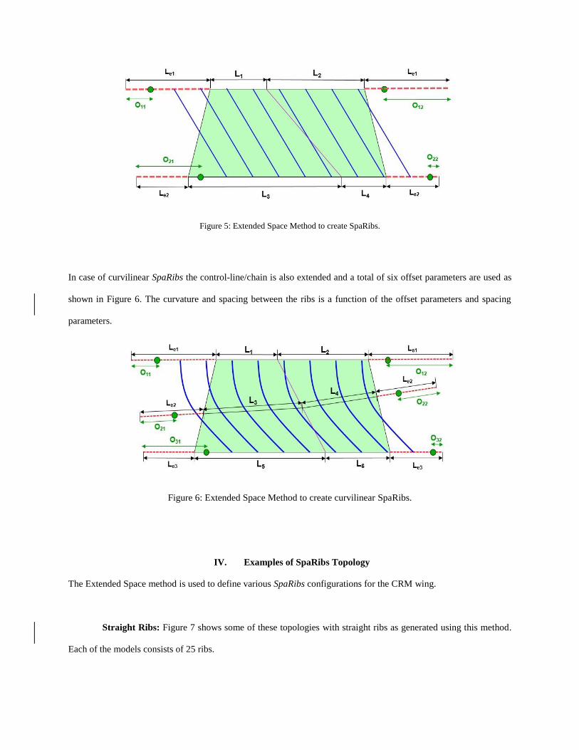
Figure 5: Extended Space Method to create SpaRibs.
In case of curvilinear SpaRibs the control-line/chain is also extended and a total of six offset parameters are used as
shown in Figure 6. The curvature and spacing between the ribs is a function of the offset parameters and spacing
parameters.
Figure 6: Extended Space Method to create curvilinear SpaRibs.
IV. Examples of SpaRibs Topology
The Extended Space method is used to define various SpaRibs configurations for the CRM wing.
Straight Ribs: Figure 7 shows some of these topologies with straight ribs as generated using this method.
Each of the models consists of 25 ribs.
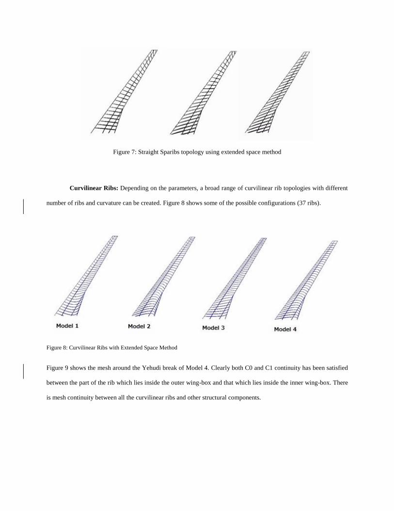
Figure 7: Straight Sparibs topology using extended space method
Curvilinear Ribs: Depending on the parameters, a broad range of curvilinear rib topologies with different
number of ribs and curvature can be created. Figure 8 shows some of the possible configurations (37 ribs).
Figure 8: Curvilinear Ribs with Extended Space Method
Figure 9 shows the mesh around the Yehudi break of Model 4. Clearly both C0 and C1 continuity has been satisfied
between the part of the rib which lies inside the outer wing-box and that which lies inside the inner wing-box. There
is mesh continuity between all the curvilinear ribs and other structural components.
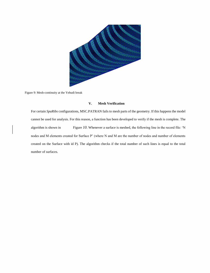
Figure 9: Mesh-continuity at the Yehudi break
V. Mesh Verification
For certain SpaRibs configurations, MSC.PATRAN fails to mesh parts of the geometry. If this happens the model
cannot be used for analysis. For this reason, a function has been developed to verify if the mesh is complete. The
algorithm is shown in Figure 10. Whenever a surface is meshed, the following line in the record file: ‘N
nodes and M elements created for Surface P’ (where N and M are the number of nodes and number of elements
created on the Surface with id P). The algorithm checks if the total number of such lines is equal to the total
number of surfaces.
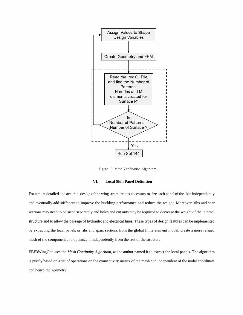
Figure 10: Mesh Verification Algorithm
VI. Local Skin Panel Definition
For a more detailed and accurate design of the wing structure it is necessary to size each panel of the skin independently
and eventually add stiffeners to improve the buckling performance and reduce the weight. Moreover, ribs and spar
sections may need to be sized separately and holes and cut outs may be required to decrease the weight of the internal
structure and to allow the passage of hydraulic and electrical lines. These types of design features can be implemented
by extracting the local panels or ribs and spars sections from the global finite element model, create a more refined
mesh of the component and optimize it independently from the rest of the structure.
EBF3WingOpt uses the Mesh Continuity Algorithm, as the author named it to extract the local panels. The algorithm
is purely based on a set of operations on the connectivity matrix of the mesh and independent of the nodal coordinate
and hence the geometry.
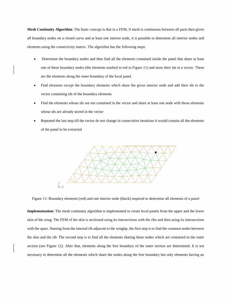
Mesh Continuity Algorithm: The basic concept is that in a FEM, if mesh is continuous between all parts then given
all boundary nodes on a closed curve and at least one interior node, it is possible to determine all interior nodes and
elements using the connectivity matrix. The algorithm has the following steps:
Determine the boundary nodes and then find all the elements contained inside the panel that share at least
one of these boundary nodes (the elements marked in red in Figure 11) and store their ids in a vector. These
are the elements along the outer boundary of the local panel.
Find elements except the boundary elements which share the given interior node and add their ids to the
vector containing ids of the boundary elements
Find the elements whose ids are not contained in the vector and share at least one node with those elements
whose ids are already stored in the vector
Repeated the last step till the vector do not change in consecutive iterations it would contain all the elements
of the panel to be extracted
Figure 11: Boundary elements (red) and one interior node (black) required to determine all elements of a panel
Implementation: The mesh continuity algorithm is implemented to create local panels from the upper and the lower
skin of the wing. The FEM of the skin is sectioned using its intersections with the ribs and then using its intersections
with the spars. Starting from the internal rib adjacent to the wingtip, the first step is to find the common nodes between
the skin and the rib. The second step is to find all the elements sharing these nodes which are contained in the outer
section (see Figure 12). After that, elements along the free boundary of the outer section are determined. It is not
necessary to determine all the elements which share the nodes along the free boundary but only elements having an
edge along it is sufficient. These boundary elements are used to find all elements of the outer section of the FEM using
the mesh continuity algorithm.
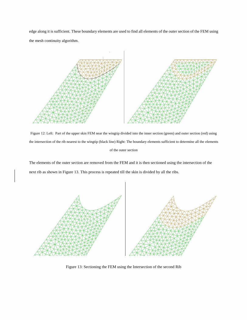
Figure 12: Left: Part of the upper skin FEM near the wingtip divided into the inner section (green) and outer section (red) using
the intersection of the rib nearest to the wingtip (black line) Right: The boundary elements sufficient to determine all the elements
of the outer section
The elements of the outer section are removed from the FEM and it is then sectioned using the intersection of the
next rib as shown in Figure 13. This process is repeated till the skin is divided by all the ribs.
Figure 13: Sectioning the FEM using the Intersection of the second Rib

The entire process is carried out using the family of spars. The set of nodes and set of elements common to each of
the segments formed using the ribs’ intersection and the segments formed using the spars’ intersection if not null is
used to form the FEM of a local panels as shown in Figure 14.
The boundary nodes for each of the segment is already determined in the process. Thus the nodes in the union of set
of boundary nodes of the segment formed by the ribs and set of boundary nodes of the segment formed by the spars
that are shared by elements of the local panel are its boundary nodes.
Figure 14: (1) Section of skin by ribs (2) Section of skin by spars (3) Common elements i.e. a local panel bounded by sparibs
(enlarged view provided in adjacent box)
The advantage of this method is that it is completely based on set operation on the connectivity data of the FEM and
independent of the coordinates of the nodes of the finite element model. It is also independent of the order in which
the elements are distributed in the FEM. Thus this method can be used to create local panels no matter where the
Sparibs start and where they end inside the wing. The local panels can have three, four or more number of edges.
Figure 15 shows an example where a five-edged local panel is created out of a wing FEM.
Another advantage of this method is that the boundary nodes of each of the local panels is already determined and the
information is stored to be used to impose boundary conditions during the optimization process.
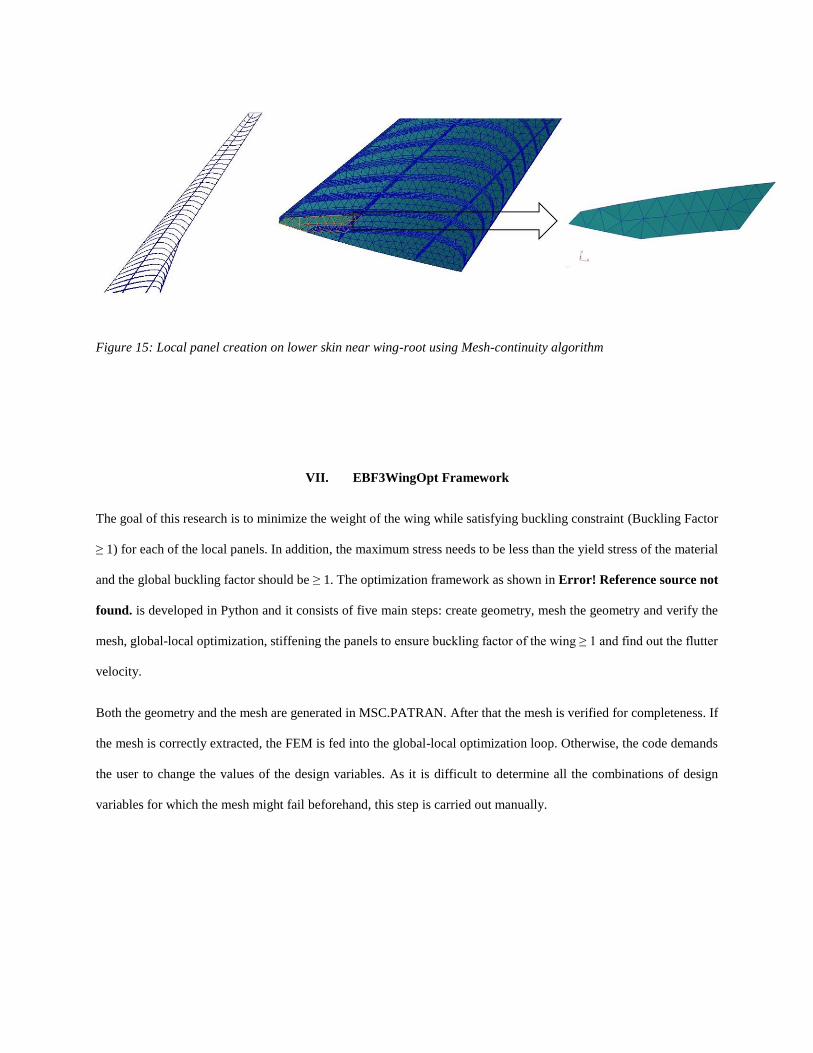
Figure 15: Local panel creation on lower skin near wing-root using Mesh-continuity algorithm
VII. EBF3WingOpt Framework
The goal of this research is to minimize the weight of the wing while satisfying buckling constraint (Buckling Factor
≥ 1) for each of the local panels. In addition, the maximum stress needs to be less than the yield stress of the material
and the global buckling factor should be ≥ 1. The optimization framework as shown in Error! Reference source not
found. is developed in Python and it consists of five main steps: create geometry, mesh the geometry and verify the
mesh, global-local optimization, stiffening the panels to ensure buckling factor of the wing ≥ 1 and find out the flutter
velocity.
Both the geometry and the mesh are generated in MSC.PATRAN. After that the mesh is verified for completeness. If
the mesh is correctly extracted, the FEM is fed into the global-local optimization loop. Otherwise, the code demands
the user to change the values of the design variables. As it is difficult to determine all the combinations of design
variables for which the mesh might fail beforehand, this step is carried out manually.
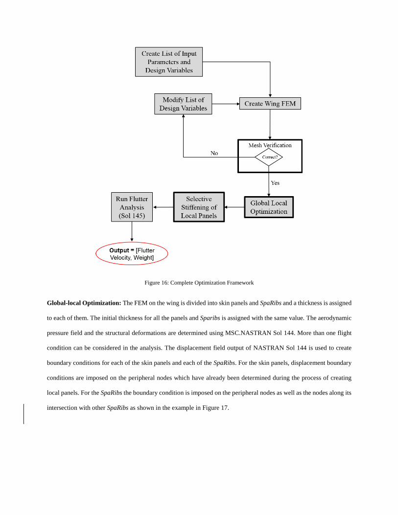
Figure 16: Complete Optimization Framework
Global-local Optimization: The FEM on the wing is divided into skin panels and SpaRibs and a thickness is assigned
to each of them. The initial thickness for all the panels and Sparibs is assigned with the same value. The aerodynamic
pressure field and the structural deformations are determined using MSC.NASTRAN Sol 144. More than one flight
condition can be considered in the analysis. The displacement field output of NASTRAN Sol 144 is used to create
boundary conditions for each of the skin panels and each of the SpaRibs. For the skin panels, displacement boundary
conditions are imposed on the peripheral nodes which have already been determined during the process of creating
local panels. For the SpaRibs the boundary condition is imposed on the peripheral nodes as well as the nodes along its
intersection with other SpaRibs as shown in the example in Figure 17.

Figure 17: Boundary Conditions. The cyan dots represent nodes where boundary conditions are imposed. (Top: Skin panel,
Middle: Rib, Bottom: Spar)
The thickness of each of the local component is optimized thereafter by running NASTRAN Sol 200 and the thickness
is updated in the respective .bdf file. A new .bdf file of the global wing is created by merging .bdf files of all the local
components and NASTRAN Sol 144 is run using the new .bdf file. As the thickness of the elements have been changed,
this will output a different displacement field than the one obtained previously. New boundary conditions are imposed
on the local components and they are re-optimized followed by updating the thickness in the .bdf files. This process
continues in an iterative way till the maximum specified number of iterations is reached. The global-local optimization
framework is shown in Figure 18.
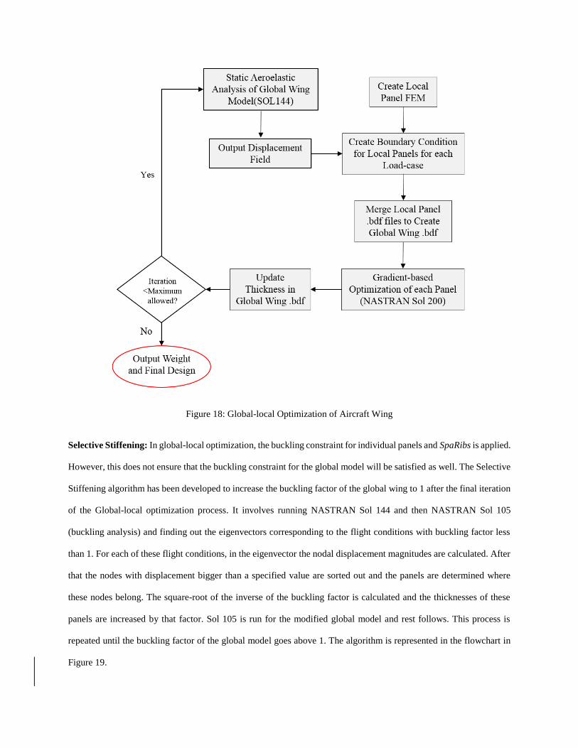
Figure 18: Global-local Optimization of Aircraft Wing
Selective Stiffening: In global-local optimization, the buckling constraint for individual panels and SpaRibs is applied.
However, this does not ensure that the buckling constraint for the global model will be satisfied as well. The Selective
Stiffening algorithm has been developed to increase the buckling factor of the global wing to 1 after the final iteration
of the Global-local optimization process. It involves running NASTRAN Sol 144 and then NASTRAN Sol 105
(buckling analysis) and finding out the eigenvectors corresponding to the flight conditions with buckling factor less
than 1. For each of these flight conditions, in the eigenvector the nodal displacement magnitudes are calculated. After
that the nodes with displacement bigger than a specified value are sorted out and the panels are determined where
these nodes belong. The square-root of the inverse of the buckling factor is calculated and the thicknesses of these
panels are increased by that factor. Sol 105 is run for the modified global model and rest follows. This process is
repeated until the buckling factor of the global model goes above 1. The algorithm is represented in the flowchart in
Figure 19.
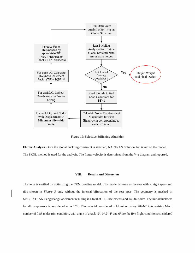
Figure 19: Selective Stiffening Algorithm
Flutter Analysis: Once the global buckling constraint is satisfied, NASTRAN Solution 145 is run on the model.
The PKNL method is used for the analysis. The flutter velocity is determined from the V-g diagram and reported.
VIII. Results and Discussion
The code is verified by optimizing the CRM baseline model. This model is same as the one with straight spars and
ribs shown in Figure 3 only without the internal bifurcation of the rear spar. The geometry is meshed in
MSC.PATRAN using triangular element resulting in a total of 31,510 elements and 14,587 nodes. The initial thickness
for all components is considered to be 0.2in. The material considered is Aluminum alloy 2024-T.3. A cruising Mach
number of 0.85 under trim condition, with angle of attack -2°, 0°,2°,4° and 6° are the five flight conditions considered
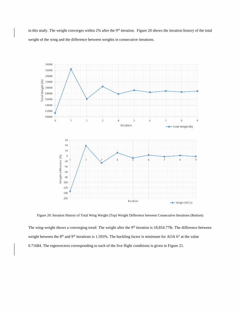
in this study. The weight converges within 2% after the 9th iteration. Figure 20 shows the iteration history of the total
weight of the wing and the difference between weights in consecutive iterations.
Figure 20: Iteration History of Total Wing Weight (Top) Weight Difference between Consecutive Iterations (Bottom)
The wing-weight shows a converging trend. The weight after the 9th iteration is 18,854.77lb. The difference between
weight between the 8th and 9th iterations is 1.593%. The buckling factor is minimum for AOA 6° at the value
0.71684. The eigenvectors corresponding to each of the five flight conditions is given in Figure 21.
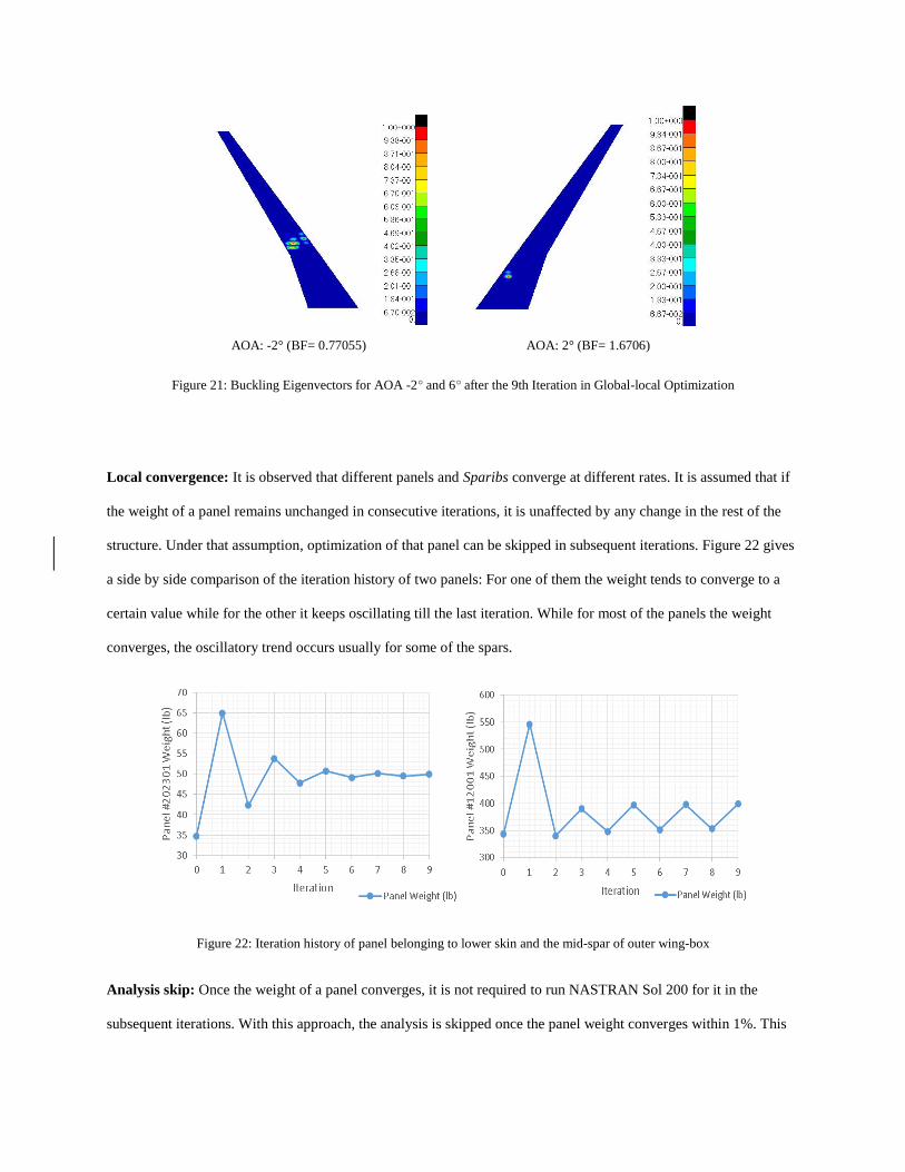
Figure 21: Buckling Eigenvectors for AOA -2° and 6° after the 9th Iteration in Global-local Optimization
Local convergence: It is observed that different panels and Sparibs converge at different rates. It is assumed that if
the weight of a panel remains unchanged in consecutive iterations, it is unaffected by any change in the rest of the
structure. Under that assumption, optimization of that panel can be skipped in subsequent iterations. Figure 22 gives
a side by side comparison of the iteration history of two panels: For one of them the weight tends to converge to a
certain value while for the other it keeps oscillating till the last iteration. While for most of the panels the weight
converges, the oscillatory trend occurs usually for some of the spars.
Figure 22: Iteration history of panel belonging to lower skin and the mid-spar of outer wing-box
Analysis skip: Once the weight of a panel converges, it is not required to run NASTRAN Sol 200 for it in the
subsequent iterations. With this approach, the analysis is skipped once the panel weight converges within 1%. This
AOA: -2° (BF= 0.77055) AOA: 2° (BF= 1.6706)
has resulted in significant decrease in the computational cost. The total computation time decreased from 21hr 42
min to 13hr 45 min (36.6% reduction).
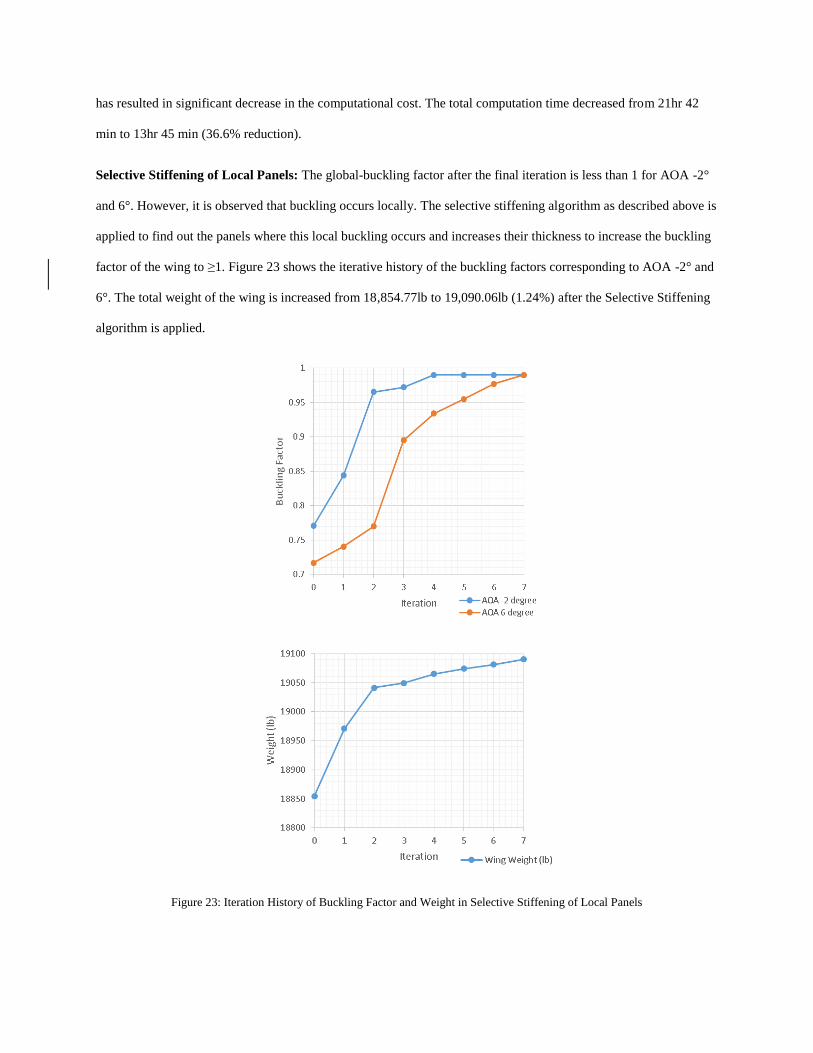
Selective Stiffening of Local Panels: The global-buckling factor after the final iteration is less than 1 for AOA -2°
and 6°. However, it is observed that buckling occurs locally. The selective stiffening algorithm as described above is
applied to find out the panels where this local buckling occurs and increases their thickness to increase the buckling
factor of the wing to ≥1. Figure 23 shows the iterative history of the buckling factors corresponding to AOA -2° and
6°. The total weight of the wing is increased from 18,854.77lb to 19,090.06lb (1.24%) after the Selective Stiffening
algorithm is applied.
Figure 23: Iteration History of Buckling Factor and Weight in Selective Stiffening of Local Panels
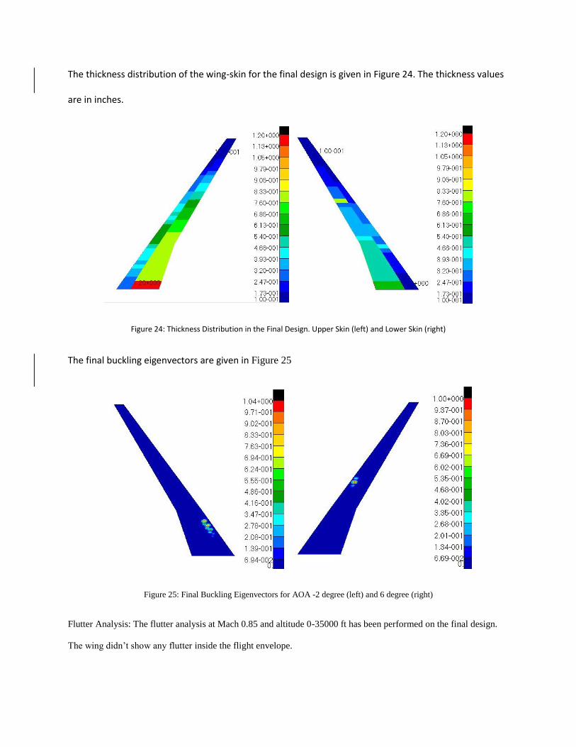
The thickness distribution of the wing-skin for the final design is given in Figure 24. The thickness values
are in inches.
Figure 24: Thickness Distribution in the Final Design. Upper Skin (left) and Lower Skin (right)
The final buckling eigenvectors are given in Figure 25
Figure 25: Final Buckling Eigenvectors for AOA -2 degree (left) and 6 degree (right)
Flutter Analysis: The flutter analysis at Mach 0.85 and altitude 0-35000 ft has been performed on the final design.
The wing didn’t show any flutter inside the flight envelope.
IX. Conclusion
This study is a step towards the development of the EBF3WingOpt software by Kapania et al. at Virginia Tech that
will exhibit multi-disciplinary multi-objective optimization capability as well as a provision for creating Sparibs
geometry for a wide range of aircraft wings. In future this optimization framework will be integrated into a Multi-
objective, Particle Swarm Optimization code to optimize Sparibs topology to reduce weight and maximize flutter
velocity. The creation of Sparibs using limited number of parameters will reduce the required number of design
variables and hence will be of a great advantage in this computationally intensive multi-objective multi-disciplinary
optimization problem. The code has been generalized enough to take into consideration Sparibs which do not
necessarily start at the leading spar and ends in the trailing spar, thus will increase the design space.
X. Acknowledgement
This effort was funded by the NASA SBIR/STTR program, under contracts NNX14CD16P and NNX15CD08C.
XI. References
1 L. A. Schmit, "Structural Synthesis: Its Genesis and Development," AIAA Journal, vol. 19, no. 10, p. 1249–1263,
1981.
2 L. A. Schmit and R. K. Ramanathan, "Multilevel Approach to Minimum Weight Design Including Buckling
Constraints," AIAA Journal, vol. 16, no. 2, p. 97–104, 1978.
3 L. A. Schmit, "Structural Design by Systematic Synthesis," Pittsburg, 1960.
4 R. T. Haftka, J. H. Starnes Jr., F. W. Barton and S. C. Dixon, "Comparison of Two Types of Optimization Procedures
for Flutter Requirements," AIAA Journal, vol. 13, no. 10, p. 1333–1339, 1975.
5 R. T. Haftka, "Optimization of Flexible Wing Structures Subject to Strength and Induced Drag Constraints," AIAA
Journal, vol. 15, no. 8, pp. 1101-1106, 1977.
6 J. H. Starnes Jr. and R. T. Haftka, "Preliminary Design of Composite Wings for Buckling, Strength, and
Displacement Constraints," Journal of Aircraft, vol. 16, no. 8, p. 564–570, 1979.
7 R. E. Fulton, J. Sobieszczanski, 0. Storaasli, E. J. Landrum and D. Loendor, "Application of Computer-Aided Aircraft
Design in a Multidisciplinary Environment," Journal of Aircraft, vol. 11, no. 7, p. 369–370, 1974.
8 K. M. Taminger and R. A. Hafley, Electron Beam Freeform Fabrication for Cost Effective Near-Net Shape
Manufacturing, Hampton, VA: NATO/RTOAVT-139 specialists’ meeting on cost effective manufacture via net shape
processing. Amsterdam (The Netherlands): NATO; , 2006.
9 D. Locatelli, S. B. Mulani and R. K. Kapania, "Wing-Box Weight Optimization Using Curvilinear Spars and Ribs
(SpaRibs)," Journal of Aircraft, vol. 48, no. 5, pp. 1671-1684, 2011.
10 Q. Liu, M. Jrad, S. B. Mulani and R. K. Kapania, "Global/Local Optimization of Aircraft Wing Using Parallel
Processing," AIAA Journal, vol. 54, no. 11, pp. 3338-3348, 2016.
11 D. Locatelli, A. Y. Tamijani, S. B. Mulani and R. K. Kapania, "Multidisciplinary Optimization of Supersonic Wing
Structures Using Curvilinear Spars and Ribs (SpaRibs)," in 54th AIAA/ASME/ASCE/AHS/ASC Structures, Structural
Dynamics, and Materials Conference, Structures, Structural Dynamics, and Materials and Co-located Conferences,
AIAA 2013-1931, Boston, Massachusetts, 2013.
12 A. Dubois, C. Farhat and A. H. Abukhwejah, "Parameterization Framework for Aeroelastic Design Optimization of
Bio-Inspired Wing Structural Layouts," in 57th AIAA/ASCE/AHS/ASC Structures, Structural Dynamics, and Materials
Conference, AIAA 2016-0485, San Diego, California, 2016.
13 S. B. Mulani, D. Locatelli and R. K. Kapania, "Algorithm Development for Optimization of Arbitrary Geometry
Panels using Curvilinear Stiffeners," in 1st AIAA/ASME/ASCE/AHS/ASC Structures, Structural Dynamics and
Materials Conf., AIAA Paper 2010-2674, 2010.
14 S. B. Mulani, W. C. H. Slemp and R. K. Kapania, "EBF3PanelOpt: An Optimization Framework for Curvilinear Blade-
Stiffened Panels," Thin-Walled Structures, vol. 63, p. 13–26, 2013.

15 M. Jrad, S. B. Mulani and R. K. Kapania, "A Framework for Damage Tolerance and Optimization of Stiffened
Panels," in International workshop on structural health monitoring, Stanford University, Stanford, CA, 2015.
16 C. V. Jutte, B. K. Stanford and C. D. Wieseman, "Internal Structural Design of the Common, Research Model Wing
Box for Aeroelastic, Tailoring," 2015.
[17] Wrik Mallik, Rakesh K. Kapania, Joseph A. Schetz , Effect of Flutter on the Multidisciplinary Design
Optimization of Truss-Braced-Wing Aircraft. Journal of Aircraft, 2015.
[18] Sierra M. R., Coello C.A. C. , Multi-Objective Particle Swarm Optimizers: A Survey of the State-of-the-Art. 3,
2006, International Journal of Computational Intelligence Research, Vol. 2, pp. 287-308.