spare parts list return line filter rfm - hydac-na.com parts list return line filter rfm ... item...
TRANSCRIPT
Spare Parts ListReturn Line Filter RFMFlow rates up to 850 l/minPressure range up to 10 barMaterial: Aluminium/Steel/Synthetic
2
1. MAINTENANCEINSTRUCTIONS
1.1. SAFETY INSTRUCTIONS
This pressure unit must onlybe operated in conjunctionwith a machine or a system.
The pressure unit must only beused in accordance with therequirements of the operatinginstructions of the machine orsystem.
This pressure unit must onlybe operated using hydraulic orlubricating fluid.
The user must take appropriateaction (e.g. venting) to preventthe formation of air pockets.
Repair, maintenance work andcommissioning must only becarried out by trainedpersonnel.Ensure the pressure unit hascooled down before handling.The stipulations of theoperating instructions of themachine or the system must befollowed.
Information
Information
Caution
Caution
Information
Caution: pressure unit! Beforeany work is carried out on thepressure unit, ensure thepressure chamber concerned(filter housing) isdepressurized.
On no account must anyalterations (welding, drilling, oropening by force…) be carriedout on the pressure unit.
It is the responsibility of theoperator to comply with thewater regulations of thecountry concerned.
Statutory accident preventionregulations, safety regulationsand safety data sheets forfluids must be observed.
When working on, or in thevicinity of, hydraulic systems,naked flames, spark generationand smoking are forbidden.
Hydraulic oils and waterpolluting fluids must not beallowed to enter the soil orwatercourses or seweragesystems. Please ensure safeand environmentally friendlydisposal of hydraulic oils andfluids. The relevantregulations in the countryconcerned with regard toground water pollution, usedoil and waste must becomplied with.
Caution
Caution
Caution
Information
Whenever work is carried outon the filter, be prepared forhot oil to escape which cancause injury or scalding due tohigh pressure or hightemperature.
Filter housings must beearthed.
When using electrical cloggingindicators, the electrical powersupply to the system must beswitched off before removingthe clogging indicatorconnector.
Caution
Caution
Danger
Danger
Danger
3
1.2. INSTALLATION
Before fitting the filter into the system, check that thepermissible operating pressure of the system does notexceed the operating pressure of the filter.
Refer to the type code label on the filter!
1.3. COMMISSIONING
Check that the correct filter element is fitted. Screw oncover plate, or replace cover plate and then tighten the4 cover plate bolts alternately.
Switch on hydraulic system and check filter for leakage.Vent filter at an appropriate point in the system.
1.4. TOOLS REQUIRED FOR MAINTENANCE
Size Allen key for max.cover plate torquebolts
RFM 75 – 15 Nm
RFM 90/150 – 10 Nm
RFM 165/185 – 15 Nm
RFM 210/270 – 30 Nm
RFM 330/500 SW 8 35 Nm
RFM 661/851 SW 10 35 Nm
1.5. TORQUE VALUES FOR CLOGGING INDICATORS
Type max. torqueVR... 30 Nm
VMF... 15 Nm
1.6. WARNING NOTES
– If a pipe extension is to be fitted to the outlet of the two-piece filter housing, the pipe must be made of syntheticmaterial or thin-wall aluminium.
– Extensions must be protected by fitting a bulkhead orother means of protection so that no forces can betransmitted to the filter housing or the extension.
– The filter can normally only be used for tank-mounting
– The filter must be fitted absolutely vertically, or, afterconsultation with the manufacturer, only within thetolerances specified.
– The filter must not be used as a suction filter.
– Components (e.g. coolers) must not be fitted after thefilter.
– Special models on request.
1.7. SERVICE ADDRESSES
Oil service:HYDAC InternationalServicetechnik, Werk 6IndustriegebietD-66280 Sulzbach/SaarTel.: 06897/509-333Fax.: 06897/509-846
Customer service:HYDAC InternationalZentraler Kundendienst, Werk 6IndustriegebietD-66280 Sulzbach/SaarTel.: 06897/509-412Fax.: 06897/509-634
Or at all national and international HYDAC sales andservice centres.
4
2. MAINTENANCE2.1. GENERAL
This section describes maintenance work which mustbe carried out periodically. The operational safety andlife expectancy of the filter, and whether it is ready foruse, depend to a large degree on regular and carefulmaintenance.
2.2. MAINTENANCE MEASURES
– Spare parts must fulfil the technical requirementsspecified by the manufacturer. This is alwaysguaranteed for HYDAC original spare parts
– Keep tools, working area and equipment clean.
– After disassembling the filter, clean all parts, check fordamage or wear and replace parts if necessary.
– When changing a filter element a high level ofcleanliness must be observed!
2.3. INTERVAL BETWEEN CHANGING ELEMENTS
We recommend fitting the filter with a clogging indicator(visual and/or electric or electronic) to monitor the filterelement.
If the clogging indicator responds, it is necessary tochange or to clean the filter element without delay.
If no clogging indicator is fitted, we recommendchanging the elements after specified intervals, aftermax. 1 year (changing the filter element depends on thedesign of the filter and the conditions). Higher dynamicloads across the element might necessitate shorterintervals between changes. Shorter intervals can alsobe expected during commissioning, repairs, oil changesetc. on the hydraulic system.
The standard clogging indicators only respond whenfluid is flowing through the filter. With electricalindicators the signal can also be converted into acontinuous display on the control panel. In this case thecontinuous display must be switched off during a coldstart or after changing the element.
If the clogging indicator responds during a cold startonly, it is possible that the element does not need to bechanged yet.
5
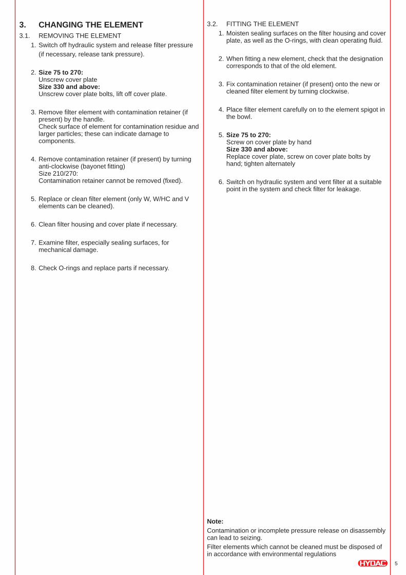
3. CHANGING THE ELEMENT3.1. REMOVING THE ELEMENT
1. Switch off hydraulic system and release filter pressure
(if necessary, release tank pressure).
2. Size 75 to 270:Unscrew cover plateSize 330 and above:Unscrew cover plate bolts, lift off cover plate.
3. Remove filter element with contamination retainer (ifpresent) by the handle.Check surface of element for contamination residue andlarger particles; these can indicate damage tocomponents.
4. Remove contamination retainer (if present) by turninganti-clockwise (bayonet fitting)Size 210/270:Contamination retainer cannot be removed (fixed).
5. Replace or clean filter element (only W, W/HC and Velements can be cleaned).
6. Clean filter housing and cover plate if necessary.
7. Examine filter, especially sealing surfaces, formechanical damage.
8. Check O-rings and replace parts if necessary.
3.2. FITTING THE ELEMENT
1. Moisten sealing surfaces on the filter housing and coverplate, as well as the O-rings, with clean operating fluid.
2. When fitting a new element, check that the designationcorresponds to that of the old element.
3. Fix contamination retainer (if present) onto the new orcleaned filter element by turning clockwise.
4. Place filter element carefully on to the element spigot inthe bowl.
5. Size 75 to 270:Screw on cover plate by handSize 330 and above:Replace cover plate, screw on cover plate bolts byhand; tighten alternately
6. Switch on hydraulic system and vent filter at a suitablepoint in the system and check filter for leakage.
Note:Contamination or incomplete pressure release on disassemblycan lead to seizing.
Filter elements which cannot be cleaned must be disposed ofin accordance with environmental regulations
6
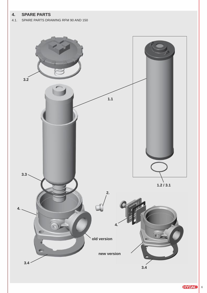
4. SPARE PARTS4.1. SPARE PARTS DRAWING RFM 90 AND 150
1.1
3.4
3.2
1.2 / 3.1
2.
3.3
4.
3.4
4.
old version
new version
7
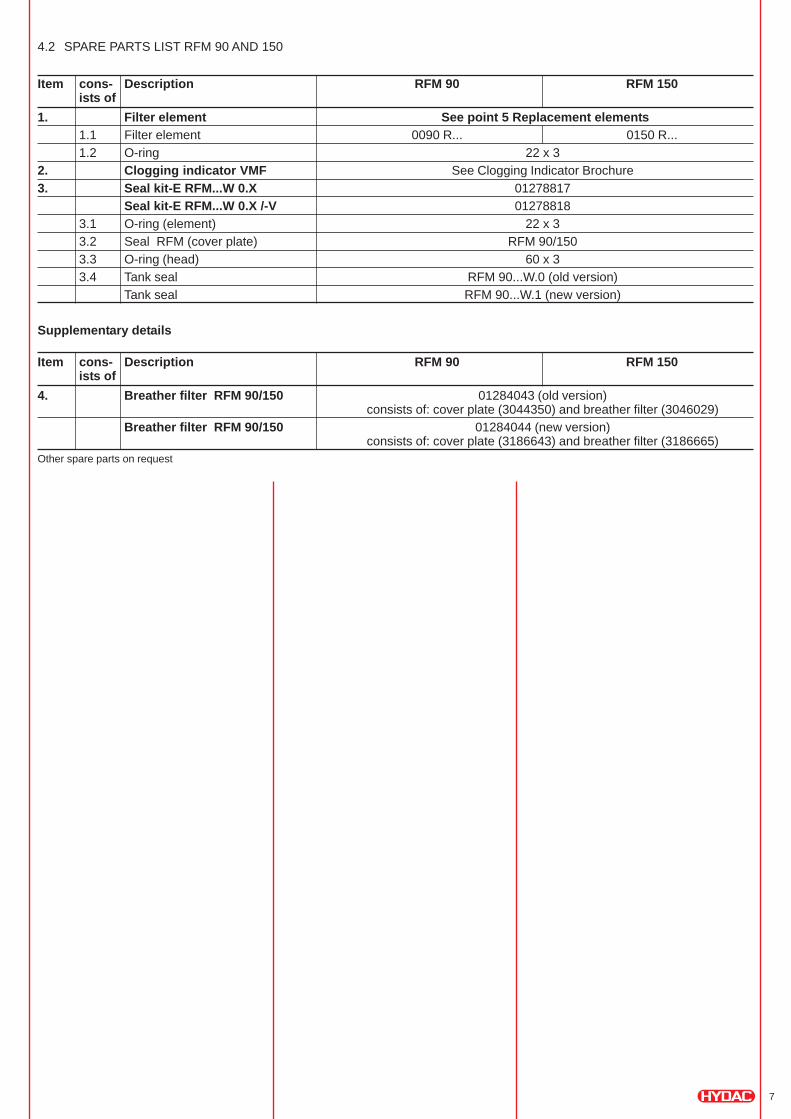
4.2 SPARE PARTS LIST RFM 90 AND 150
Item cons- Description RFM 90 RFM 150ists of
1. Filter element See point 5 Replacement elements1.1 Filter element 0090 R... 0150 R...
1.2 O-ring 22 x 3
2. Clogging indicator VMF See Clogging Indicator Brochure
3. Seal kit-E RFM...W 0.X 01278817
Seal kit-E RFM...W 0.X /-V 01278818
3.1 O-ring (element) 22 x 3
3.2 Seal RFM (cover plate) RFM 90/150
3.3 O-ring (head) 60 x 3
3.4 Tank seal RFM 90...W.0 (old version)
Tank seal RFM 90...W.1 (new version)
Supplementary details
Item cons- Description RFM 90 RFM 150ists of
4. Breather filter RFM 90/150 01284043 (old version)consists of: cover plate (3044350) and breather filter (3046029)
Breather filter RFM 90/150 01284044 (new version)consists of: cover plate (3186643) and breather filter (3186665)
Other spare parts on request
8
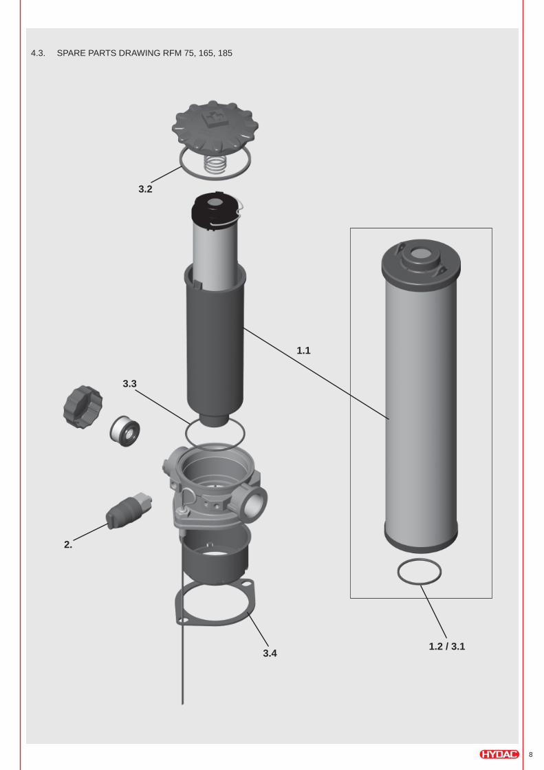
4.3. SPARE PARTS DRAWING RFM 75, 165, 185
1.1
2.
3.2
3.4
3.3
1.2 / 3.1
9
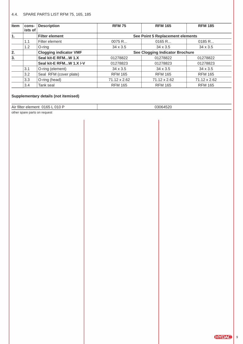
4.4. SPARE PARTS LIST RFM 75, 165, 185
Item cons- Description RFM 75 RFM 165 RFM 185ists of
1. Filter element See Point 5 Replacement elements1.1 Filter element 0075 R... 0165 R... 0185 R...
1.2 O-ring 34 x 3.5 34 x 3.5 34 x 3.5
2. Clogging indicator VMF See Clogging Indicator Brochure3. Seal kit-E RFM...W 1.X 01278822 01278822 01278822
Seal kit-E RFM...W 1.X /-V 01278823 01278823 01278823
3.1 O-ring (element) 34 x 3.5 34 x 3.5 34 x 3.5
3.2 Seal RFM (cover plate) RFM 165 RFM 165 RFM 165
3.3 O-ring (head) 71.12 x 2.62 71.12 x 2.62 71.12 x 2.62
3.4 Tank seal RFM 165 RFM 165 RFM 165
Supplementary details (not itemised)
Air filter element 0165 L 010 P 03064520other spare parts on request
10
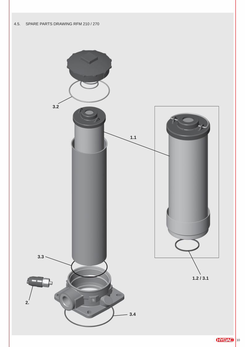
1.2 / 3.1
4.5. SPARE PARTS DRAWING RFM 210 / 270
1.1
2.
3.2
3.4
3.3
11
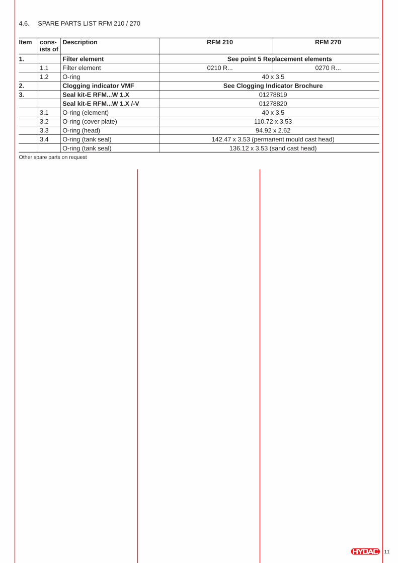
4.6. SPARE PARTS LIST RFM 210 / 270
Item cons- Description RFM 210 RFM 270ists of
1. Filter element See point 5 Replacement elements1.1 Filter element 0210 R... 0270 R...
1.2 O-ring 40 x 3.5
2. Clogging indicator VMF See Clogging Indicator Brochure3. Seal kit-E RFM...W 1.X 01278819
Seal kit-E RFM...W 1.X /-V 01278820
3.1 O-ring (element) 40 x 3.5
3.2 O-ring (cover plate) 110.72 x 3.53
3.3 O-ring (head) 94.92 x 2.62
3.4 O-ring (tank seal) 142.47 x 3.53 (permanent mould cast head)
O-ring (tank seal) 136.12 x 3.53 (sand cast head)Other spare parts on request
12
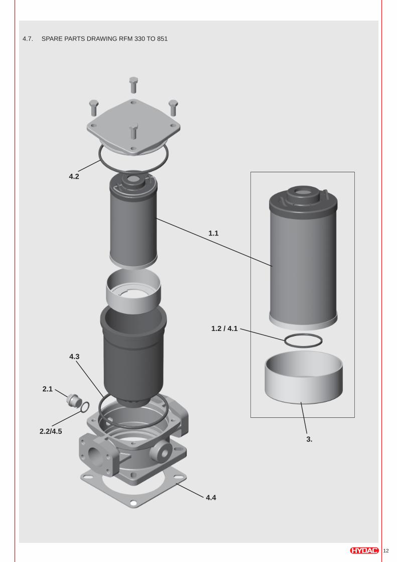
4.7. SPARE PARTS DRAWING RFM 330 TO 851
1.1
2.2/4.5
4.2
3.
4.4
4.3
1.2 / 4.1
2.1
13
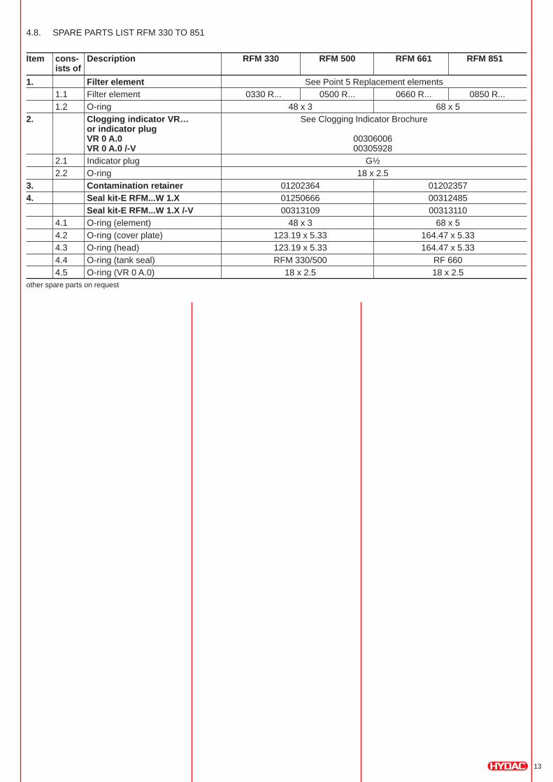
4.8. SPARE PARTS LIST RFM 330 TO 851
Item cons- Description RFM 330 RFM 500 RFM 661 RFM 851ists of
1. Filter element See Point 5 Replacement elements
1.1 Filter element 0330 R... 0500 R... 0660 R... 0850 R...
1.2 O-ring 48 x 3 68 x 5
2. Clogging indicator VR… See Clogging Indicator Brochureor indicator plugVR 0 A.0 00306006VR 0 A.0 /-V 00305928
2.1 Indicator plug G½
2.2 O-ring 18 x 2.5
3. Contamination retainer 01202364 01202357
4. Seal kit-E RFM...W 1.X 01250666 00312485
Seal kit-E RFM...W 1.X /-V 00313109 00313110
4.1 O-ring (element) 48 x 3 68 x 5
4.2 O-ring (cover plate) 123.19 x 5.33 164.47 x 5.33
4.3 O-ring (head) 123.19 x 5.33 164.47 x 5.33
4.4 O-ring (tank seal) RFM 330/500 RF 660
4.5 O-ring (VR 0 A.0) 18 x 2.5 18 x 2.5other spare parts on request
14
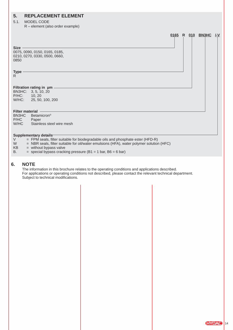
5. REPLACEMENT ELEMENT5.1. MODEL CODE
R – element (also order example)
0165 R 010 BN3HC /-V
Size0075, 0090, 0150, 0165, 0185,0210, 0270, 0330, 0500, 0660,0850
TypeR
Filtration rating in µmBN3HC: 3, 5, 10, 20P/HC: 10, 20W/HC: 25, 50, 100, 200
Filter materialBN3HC Betamicron®
P/HC PaperW/HC Stainless steel wire mesh
Supplementary detailsV = FPM seals, filter suitable for biodegradable oils and phosphate ester (HFD-R)W = NBR seals, filter suitable for oil/water emulsions (HFA), water polymer solution (HFC)KB = without bypass valveB. = special bypass cracking pressure (B1 = 1 bar, B6 = 6 bar)
6. NOTEThe information in this brochure relates to the operating conditions and applications described.For applications or operating conditions not described, please contact the relevant technical department.Subject to technical modifications.

15
NOTES: