sparc international, inc. · the sparc architecture manual version 9 sparc international, inc. san...
TRANSCRIPT
32
The SPARC Architecture Manual
Version 9
SPARC International, Inc.San Jose, California
David L. Weaver / Tom Germond
Editors
SAV09R1459912
PT R Prentice Hall, Englewood Cliffs, New Jersey 076

n anyt the
tor
SPARC® is a registered trademark of SPARC International, Inc.
The SPARC logo is a registered trademark of SPARC International, Inc.
UNIX® is a registered trademark of UNIX System Laboratories, Inc.
Copyright © 1994 SPARC International, Inc.
Published by PTR Prentice HallPrentice-Hall, Inc.A Paramount Communications CompanyEnglewood Cliffs, New Jersey 07632
The publisher offers discounts on this book when ordered in bulk quantities. For moreinformation, contact:
Corporate Sales DepartmentPT R Prentice Hall113 Sylvan AvenueEnglewood Cliffs, NJ 07632
Phone: (201) 592-2863Fax: (201) 592-2249
All rights reserved.
No part of this publication may be reproduced, stored in a retrieval system, or transmitted iform or by any means, electronic, mechanical, photocopying, recording or otherwise, withouprior permission of the copyright owners.
Restricted rights legend: use, duplication, or disclosure by the U. S. Government is subjectrestrictions set forth in subparagraph (c)(1)(ii) of the Rights in Technical Data and ComputeSoftware clause atDFARS 52.227-7013 and in similar clauses in theFAR andNASA FAR Sup-plement.
Printed in the United States of America
10 9 8 7 6 5 4 3 2 1
ISBN 0-13-825001-4
PRENTICE-HALL INTERNATIONAL (UK) LIMITED, LondonPRENTICE-HALL OF AUSTRALIA PTY. LIMITED, SydneyPRENTICE-HALL CANADA INC., TorontoPRENTICE-HALL HISPANOAMERICANA, S.A.,MexicoPRENTICE-HALL OF INDIA PRIVATE LIMITED, New DelhiPRENTICE-HALL OF JAPAN, INC., Tokyo

SIMON & SCHUSTER ASIA PTE. LTD., SingaporeEDITORA PRENTICE-HALL DO BRASIL, LTDA., Rio de Janeiro
Contents
Introduction ............................................................................................................. xiii0.1 SPARC .................................................................................................... xiii0.2 Processor Needs for the 90s and Beyond ................................................ xiv0.3 SPARC-V9: A Robust RISC for the Next Century ................................ xiv
0.3.1 64-bit Data and Addresses ....................................................... xiv0.3.2 Improved System Performance ................................................ xv0.3.3 Advanced Optimizing Compilers ............................................ xvi0.3.4 Advanced Superscalar Processors ............................................ xvii0.3.5 Advanced Operating Systems .................................................. xvii0.3.6 Fault Tolerance ........................................................................ xviii0.3.7 Fast Traps and Context Switching ........................................... xviii0.3.8 Big- and Little-Endian Byte Orders ......................................... xix
0.4 Summary ................................................................................................. xix
Editors’ Notes .......................................................................................................... xxiAcknowledgments ............................................................................................... xxiPersonal Notes .................................................................................................... xxi
1 Overview ............................................................................................................ 11.1 Notes About this Book ............................................................................ 1
1.1.1 Audience .................................................................................. 11.1.2 Where to Start .......................................................................... 11.1.3 Contents ................................................................................... 11.1.4 Editorial Conventions .............................................................. 3
1.2 The SPARC-V9 Architecture ................................................................. 41.2.1 Features .................................................................................... 41.2.2 Attributes .................................................................................. 51.2.3 System Components ................................................................ 61.2.4 Binary Compatibility ............................................................... 61.2.5 Architectural Definition ........................................................... 71.2.6 SPARC-V9 Compliance .......................................................... 7
2 Definitions .......................................................................................................... 9
3 Architectural Overview .................................................................................... 153.1 SPARC-V9 Processor ............................................................................. 15
3.1.1 Integer Unit (IU) ...................................................................... 153.1.2 Floating-Point Unit (FPU) ...................................................... 16
3.2 Instructions .............................................................................................. 163.2.1 Memory Access ....................................................................... 17

3.2.2 Arithmetic/Logical/Shift Instructions ...................................... 193.2.3 Control Transfer ....................................................................... 193.2.4 State Register Access ............................................................... 203.2.5 Floating-Point Operate ............................................................. 203.2.6 Conditional Move .................................................................... 203.2.7 Register Window Management ................................................ 20
3.3 Traps ....................................................................................................... 21
4 Data Formats ..................................................................................................... 234.1 Signed Integer Byte ................................................................................. 234.2 Signed Integer Halfword ......................................................................... 244.3 Signed Integer Word ............................................................................... 244.4 Signed Integer Double ............................................................................ 244.5 Signed Extended Integer ......................................................................... 244.6 Unsigned Integer Byte ............................................................................ 244.7 Unsigned Integer Halfword ..................................................................... 244.8 Unsigned Integer Word ........................................................................... 254.9 Unsigned Integer Double ........................................................................ 254.10 Unsigned Extended Integer ..................................................................... 254.11 Tagged Word .......................................................................................... 254.12 Floating-Point Single Precision .............................................................. 254.13 Floating-Point Double Precision ............................................................. 264.14 Floating-Point Quad Precision ................................................................ 26
5 Registers............................................................................................................. 295.1 Nonprivileged Registers .......................................................................... 30
5.1.1 General Purposer Registers ..................................................... 305.1.2 Specialr Registers ................................................................... 345.1.3 IU Control/Status Registers ..................................................... 355.1.4 Floating-Point Registers .......................................................... 365.1.5 Condition Codes Register (CCR) ............................................ 405.1.6 Floating-Point Registers State (FPRS) Register ...................... 425.1.7 Floating-Point State Register (FSR) ........................................ 435.1.8 Address Space Identifier Register (ASI) ................................. 505.1.9 TICK Register (TICK) ............................................................. 50
5.2 Privileged Registers ................................................................................ 515.2.1 Processor State Register (PSTATE) ........................................ 515.2.2 Trap Level Register (TL) ......................................................... 545.2.3 Processor Interrupt Level (PIL) ............................................... 545.2.4 Trap Program Counter (TPC) .................................................. 555.2.5 Trap Next Program Counter (TNPC) ....................................... 55
5.2.6 Trap State (TSTATE) .............................................................. 565.2.7 Trap Type Register (TT) .......................................................... 565.2.8 Trap Base Address (TBA) ....................................................... 575.2.9 Version Register (VER) ........................................................... 575.2.10 Register-Window State Registers ............................................ 585.2.11 Ancillary State Registers (ASRs) ............................................. 605.2.12 Floating-Point Deferred-Trap Queue (FQ) .............................. 615.2.13 IU Deferred-Trap Queue .......................................................... 61
6 Instructions ........................................................................................................ 636.1 Instruction Execution .............................................................................. 636.2 Instruction Formats ................................................................................. 63
6.2.1 Instruction Fields ..................................................................... 666.3 Instruction Categories ............................................................................. 68
6.3.1 Memory Access Instructions .................................................... 696.3.2 Memory Synchronization Instructions ..................................... 766.3.3 Integer Arithmetic Instructions ................................................ 766.3.4 Control-Transfer Instructions (CTIs) ....................................... 776.3.5 Conditional Move Instructions ................................................ 806.3.6 Register Window Management Instructions ............................ 826.3.7 State Register Access ............................................................... 846.3.8 Privileged Register Access ...................................................... 846.3.9 Floating-Point Operate (FPop) Instructions ............................. 846.3.10 Implementation-Dependent Instructions .................................. 856.3.11 Reserved Opcodes and Instruction Fields ................................ 85
6.4 Register Window Management ............................................................... 856.4.1 Register Window State Definition ........................................... 856.4.2 Register Window Traps ........................................................... 86
7 Traps .................................................................................................................. 897.1 Overview ................................................................................................. 897.2 Processor States, Normal and Special Traps ........................................... 90
7.2.1 RED_state ................................................................................ 907.2.2 Error_state ................................................................................ 94
7.3 Trap Categories ....................................................................................... 947.3.1 Precise Traps ............................................................................ 957.3.2 Deferred Traps ......................................................................... 957.3.3 Disrupting Traps ...................................................................... 967.3.4 Reset Traps ............................................................................... 977.3.5 Uses of the Trap Categories ..................................................... 97
7.4 Trap Control ............................................................................................ 99
7.4.1 PIL Control .............................................................................. 997.4.2 TEM Control ............................................................................ 100
7.5 Trap-Table Entry Addresses ................................................................... 1007.5.1 Trap Table Organization .......................................................... 1017.5.2 Trap Type (TT) ........................................................................ 1017.5.3 Trap Priorities .......................................................................... 104
7.6 Trap Processing ....................................................................................... 1057.6.1 Normal Trap Processing ......................................................... 1067.6.2 Special Trap Processing ........................................................... 108
7.7 Exception and Interrupt Descriptions ..................................................... 113
8 Memory Models ................................................................................................ 1198.1 Introduction ............................................................................................. 1198.2 Memory, Real Memory, and I/O Locations ............................................ 1208.3 Addressing and Alternate Address Spaces ............................................. 1218.4 The SPARC-V9 Memory Model ............................................................ 123
8.4.1 The SPARC-V9 Program Execution Model ............................ 1238.4.2 The Processor/Memory Interface Model ................................. 1258.4.3 The MEMBAR Instruction ...................................................... 1268.4.4 Memory Models ....................................................................... 1288.4.5 Mode Control ........................................................................... 1298.4.6 Hardware Primitives for Mutual Exclusion ............................. 1308.4.7 Synchronizing Instruction and Data Memory .......................... 131
A Instruction Definitions (Normative) ................................................................ 133A.1 Overview ................................................................................................. 133A.2 Add .......................................................................................................... 137A.3 Branch on Integer Register with Prediction (BPr) ................................. 138A.4 Branch on Floating-Point Condition Codes (FBfcc) .............................. 140A.5 Branch on Floating-Point Condition Codes with Prediction (FBPfcc) ... 143A.6 Branch on Integer Condition Codes (Bicc) ............................................. 146A.7 Branch on Integer Condition Codes with Prediction (BPcc) ................... 148A.8 Call and Link ........................................................................................... 151A.9 Compare and Swap ................................................................................. 152A.10 Divide (64-bit / 32-bit) ............................................................................ 154A.11 DONE and RETRY ................................................................................. 157A.12 Floating-Point Add and Subtract ............................................................ 158A.13 Floating-Point Compare .......................................................................... 159A.14 Convert Floating-Point to Integer ........................................................... 161A.15 Convert Between Floating-Point Formats .............................................. 162A.16 Convert Integer to Floating-Point ........................................................... 163

A.17 Floating-Point Move ............................................................................... 164A.18 Floating-Point Multiply and Divide ........................................................ 165A.19 Floating-Point Square Root ......................................................... 166A.20 Flush Instruction Memory ...................................................................... 167A.21 Flush Register Windows ........................................................................ 169A.22 Illegal Instruction Trap ........................................................................... 170A.23 Implementation-Dependent Instructions ................................................. 171A.24 Jump and Link ......................................................................................... 172A.25 Load Floating-Point ................................................................................ 173A.26 Load Floating-Point from Alternate Space ............................................. 176A.27 Load Integer ............................................................................................ 178A.28 Load Integer from Alternate Space ......................................................... 180A.29 Load-Store Unsigned Byte ...................................................................... 182A.30 Load-Store Unsigned Byte to Alternate Space ....................................... 183A.31 Logical Operations .................................................................................. 184A.32 Memory Barrier ...................................................................................... 186A.33 Move Floating-Point Register on Condition (FMOVcc) ........................ 188A.34 Move F-P Register on Integer Register Condition (FMOVr) ................. 192A.35 Move Integer Register on Condition (MOVcc) ...................................... 194A.36 Move Integer Register on Register Condition (MOVR) ......................... 198A.37 Multiply and Divide (64-bit) ................................................................... 199A.38 Multiply (32-bit) ..................................................................................... 200A.39 Multiply Step .......................................................................................... 202A.40 No Operation ........................................................................................... 204A.41 Population Count .................................................................................... 205A.42 Prefetch Data ........................................................................................... 206
A.42.1 Prefetch Variants ...................................................................... 207A.42.2 General Comments ................................................................... 209
A.43 Read Privileged Register ......................................................................... 211A.44 Read State Register ................................................................................. 214A.45 RETURN ................................................................................................. 216A.46 SAVE and RESTORE ............................................................................. 217A.47 SAVED and RESTORED ....................................................................... 219A.48 SETHI ..................................................................................................... 220A.49 Shift ......................................................................................................... 221A.50 Software-Initiated Reset .......................................................................... 223A.51 Store Barrier ............................................................................................ 224A.52 Store Floating-Point ................................................................................ 225A.53 Store Floating-Point into Alternate Space .............................................. 227A.54 Store Integer ............................................................................................ 229

A.55 Store Integer into Alternate Space .......................................................... 231A.56 Subtract ................................................................................................... 233A.57 Swap Register with Memory .................................................................. 234A.58 Swap Register with Alternate Space Memory ........................................ 235A.59 Tagged Add ............................................................................................ 237A.60 Tagged Subtract ...................................................................................... 238A.61 Trap on Integer Condition Codes (Tcc) .................................................. 240A.62 Write Privileged Register ........................................................................ 242A.63 Write State Register .................................................................... 244
B IEEE Std 754-1985 Requirements for SPARC-V9 (Normative).................. 247B.1 Traps Inhibit Results ............................................................................... 247B.2 NaN Operand and Result Definitions ..................................................... 248
B.2.1 Untrapped Result in Different Format from Operands ............ 248B.2.2 Untrapped Result in Same Format as Operands ...................... 248
B.3 Trapped Underflow Definition (UFM = 1) ............................................. 249B.4 Untrapped Underflow Definition (UFM = 0) ......................................... 249B.5 Integer Overflow Definition ................................................................... 250B.6 Floating-Point Nonstandard Mode .......................................................... 250
C SPARC-V9 Implementation Dependencies (Normative).............................. 251C.1 Definition of an Implementation Dependency ........................................ 251C.2 Hardware Characteristics ........................................................................ 251C.3 Implementation Dependency Categories ................................................ 252C.4 List of Implementation Dependencies .................................................... 252
D Formal Specification of the Memory Models (Normative)........................... 261D.1 Processors and Memory .......................................................................... 261D.2 An Overview of the Memory Model Specification ................................ 262D.3 Memory Transactions ............................................................................. 263
D.3.1 Memory Transactions .............................................................. 263D.3.2 Program Order ......................................................................... 263D.3.3 Dependence Order ................................................................... 264D.3.4 Memory Order ......................................................................... 265
D.4 Specification of Relaxed Memory Order (RMO) ................................... 265D.4.1 Value Atomicity ....................................................................... 265D.4.2 Store Atomicity ........................................................................ 266D.4.3 Atomic Memory Transactions ................................................. 266D.4.4 Memory Order Constraints ...................................................... 266D.4.5 Value of Memory Transactions ............................................... 266D.4.6 Termination of Memory Transactions ..................................... 267
D.4.7 Flush Memory Transaction ...................................................... 267D.5 Specification of Partial Store Order (PSO) ............................................. 267D.6 Specification of Total Store Order (TSO) ............................................... 267D.7 Examples Of Program Executions .......................................................... 267
D.7.1 Observation of Store Atomicity ............................................... 267D.7.2 Dekker’s Algorithm ................................................................. 269D.7.3 Indirection Through Processors ............................................... 269D.7.4 PSO Behavior ........................................................................... 270D.7.5 Application to Compilers ......................................................... 271D.7.6 Verifying Memory Models ...................................................... 272
E Opcode Maps (Normative)............................................................................... 273E.1 Overview ................................................................................................. 273E.2 Tables ...................................................................................................... 273
F SPARC-V9 MMU Requirements (Informative) ........................................... 281F.1 Introduction ............................................................................................. 281
F.1.1 Definitions ................................................................................ 281F.2 Overview ................................................................................................. 281F.3 The Processor-MMU Interface ............................................................... 282
F.3.1 Information the MMU Expects from the Processor ................. 283F.3.2 Attributes the MMU Associates with Each Mapping .............. 284F.3.3 Information the MMU Sends to the Processor ........................ 284
F.4 Components of the SPARC-V9 MMU Architecture .............................. 285F.4.1 Virtual-to-Physical Address Translation .................................. 285F.4.2 Memory Protection .................................................................. 286F.4.3 Prefetch and Non-Faulting Load Violation .............................. 286F.4.4 Contexts ................................................................................... 286F.4.5 Fault Status and Fault Address ................................................ 287F.4.6 Referenced and Modified Statistics ......................................... 288
F.5 RED_state Processing ............................................................................. 288F.6 Virtual Address Aliasing ......................................................................... 288F.7 MMU Demap Operation ......................................................................... 288F.8 SPARC-V9 Systems without an MMU .................................................. 289
G Suggested Assembly Language Syntax (Informative).................................. 291G.1 Notation Used ......................................................................................... 291
G.1.1 Register Names ........................................................................ 291G.1.2 Special Symbol Names ............................................................ 292G.1.3 Values ...................................................................................... 294G.1.4 Labels ....................................................................................... 295

G.1.5 Other Operand Syntax .............................................................. 295G.1.6 Comments ................................................................................ 296
G.2 Syntax Design ......................................................................................... 296G.3 Synthetic Instructions ............................................................................. 297
H Software Considerations (Informative) ......................................................... 301H.1 Nonprivileged Software .......................................................................... 301
H.1.1 Registers ................................................................................... 301H.1.2 Leaf-Procedure Optimization .................................................. 304H.1.3 Example Code for a Procedure Call ......................................... 306H.1.4 Register Allocation within a Window ..................................... 307H.1.5 Other Register-Window-Usage Models .................................. 308H.1.6 Self-Modifying Code .............................................................. 308H.1.7 Thread Management ................................................................ 309H.1.8 Minimizing Branch Latency .................................................... 309H.1.9 Prefetch .................................................................................... 310H.1.10 Nonfaulting Load ..................................................................... 313
H.2 Supervisor Software ................................................................................ 315H.2.1 Trap Handling .......................................................................... 315H.2.2 Example Code for Spill Handler .............................................. 316H.2.3 Client-Server Model ................................................................. 316H.2.4 User Trap Handlers .................................................................. 317
I Extending the SPARC-V9 Architecture (Informative) ................................ 321I.1 Addition of SPARC-V9 Extensions ....................................................... 321
I.1.1 Read/Write Ancillary State Registers (ASRs) ......................... 321I.1.2 Implementation-Dependent and Reserved Opcodes ................ 321
J Programming With the Memory Models (Informative) .............................. 323J.1 Memory Operations ................................................................................ 323J.2 Memory Model Selection ....................................................................... 324J.3 Processors and Processes ........................................................................ 324J.4 Higher-Level Programming Languages and Memory Models ............... 325J.5 Portability And Recommended Programming Style ............................... 325J.6 Spin Locks .............................................................................................. 327J.7 Producer-Consumer Relationship ........................................................... 327J.8 Process Switch Sequence ........................................................................ 329J.9 Dekker’s Algorithm ................................................................................ 330J.10 Code Patching ......................................................................................... 330J.11 Fetch_and_Add ....................................................................................... 333J.12 Barrier Synchronization .......................................................................... 333
J.13 Linked List Insertion and Deletion ......................................................... 335J.14 Communicating With I/O Devices .......................................................... 335
J.14.1 I/O Registers With Side Effects ............................................... 337J.14.2 The Control and Status Register (CSR) ................................... 337J.14.3 The Descriptor ......................................................................... 338J.14.4 Lock-Controlled Access to a Device Register ......................... 338
K Changes From SPARC-V8 to SPARC-V9 (Informative) ............................. 339K.1 Trap Model .............................................................................................. 339K.2 Data Formats ........................................................................................... 340K.3 Little-Endian Support .............................................................................. 340K.4 Registers .................................................................................................. 340K.5 Alternate Space Access ........................................................................... 341K.6 Little-Endian Byte Order ........................................................................ 341K.7 Instruction Set ......................................................................................... 341K.8 Memory Model ....................................................................................... 344
Bibliography ............................................................................................................ 345General References ............................................................................................. 345Memory Model References ................................................................................. 346Prefetching .......................................................................................................... 347
Index ......................................................................................................................... 349

t wasber of
y theit isuring a
panyate onee has
en theetitors.rchi-expectoming
es-emberPARCom-
rams.ery
e sameight to
1980s.struc-early
Introduction
Welcome to SPARC-V9, the most significant change to the SPARC architecture since iannounced in 1987. SPARC-V9 extends the addresses of SPARC to 64 bits and adds a numnew instructions and other enhancements to the architecture.1
SPARC-V9, like its predecessor SPARC-V8, is a microprocessor specification created bSPARC Architecture Committee of SPARC International. SPARC-V9 is not a specific chip;an architectural specification that can be implemented as a microprocessor by anyone seclicense from SPARC International.
SPARC International is a consortium of computer makers, with membership open to any comin the world. Executive member companies each designate one voting member to participthe SPARC Architecture Committee. Over the past several years, the architecture committbeen hard at work designing the next generation of the SPARC architecture.
Typically, microprocessors are designed and implemented in secret by a single company. Thcompany spends succeeding years defending its proprietary rights in court against its compWith SPARC, it is our intention to make it easy for anyone to design and implement to this atectural specification. Several SPARC-V9 implementations are already underway, and wemany more companies to design systems around this microprocessor standard in the cyears.
0.1 SPARC
SPARC stands for aScalableProcessorARChitecture. SPARC has been implemented in procsors used in a range of computers from laptops to supercomputers. SPARC International mcompanies have implemented over a dozen different compatible microprocessors since Swas first announced—more than any other microprocessor family with this level of binary cpatibility. As a result, SPARC today boasts over 8000 compatible software application progSPARC-V9 maintains upwards binary compatibility for application software, which is a vimportant feature.
Throughout the past six years, the SPARC architecture has served our needs well. But at thtime, VLSI technology, compiler techniques and users’ needs have changed. The time is rupgrade SPARC for the coming decade.
0.2 Processor Needs for the 90s and Beyond
The design of Reduced Instruction Set Processors (RISC) began in earnest in the earlyEarly RISC processors typically were characterized by a load-store architecture, single intion-per-cycle execution, and 32-bit addressing. The instruction set architecture of these
1.For a complete list of changes between SPARC-V8 and SPARC-V9, see Appendix K.
80s,
ore fornd yeto theplat-rfaces.eads,liably
tionaces orngedht tolong
tury.plicit
s. Allal newn be
s com-ade
RISC chips was well matched to the level of computer optimization available in the early 19and provided a minimal interface for the UNIX™ operating system.
The computer industry has grown significantly in the last decade. Computer users need mthe 1990s than these early RISCs provided; they demand more powerful systems today, athey continue to want their systems to have good performance growth and compatibility intfuture.The applications of the future—highly interactive and distributed across multipleforms—will require larger address spaces and more sophisticated operating system inteTomorrow’s architectures must provide better support for multiprocessors, lightweight thrand object oriented programming. Modern computer systems must also perform more rethan in the past.
It is interesting to observe the evolution of RISC architectures. Without sufficient instrucencoding, some microprocessors have been unable to provide for either larger address spnew instruction functionality. Others have provided 64-bit addressing, but still have not chamuch from the RISCs of the 1980s. Fortunately, SPARC’s designers had sufficient foresigallow for all of the changes we felt were needed to keep SPARC a viable architecture for theterm.
0.3 SPARC-V9: A Robust RISC for the Next Century
SPARC-V9 is a robust RISC architecture that will remain competitive well into the next cenThe SPARC-V9 architecture delivers on this promise by enhancing SPARC-V8 to provide exsupport for:
— 64-bit virtual addresses and 64-bit integer data
— Improved system performance
— Advanced optimizing compilers
— Superscalar implementations
— Advanced operating systems
— Fault tolerance
— Extremely fast trap handling and context switching
— Big- and little-endian byte orders
0.3.1 64-bit Data and Addresses
SPARC-V9 directly supports 64-bit virtual addresses and integer data sizes up to 64 bitSPARC-V8 integer registers have been extended from 32 to 64 bits. There are also severinstructions that explicitly manipulate 64-bit values. For example, 64-bit integer values caloaded and stored directly with the LDX and STX instructions.
Despite these changes, 64-bit SPARC-V9 microprocessors will be able to execute programpiled for 32-bit SPARC-V8 processors. The principles of two’s complement arithmetic m

eci-its ofoces-s willpre-2-bitss. For
ilities,f thell of the
We’veer per-isters,
s togisters..
ortedne byoulde newting-
ity of
ction.ntial
t we
upward compatibility straightforward to accomplish. Arithmetic operations, for example, spfied arithmetic on registers, independent of the length of the register. The low order 32-barithmetic operations will continue to generate the same values they did on SPARC-V8 prsors. Since SPARC-V8 programs paid attention to only the low order 32-bits, these programexecute compatibly. Compatibility for SPARC-V9 was accomplished by making sure that allviously existing instructions continued to generate exactly the same result in the low order 3of registers. In some cases this meant adding new instructions to operate on 64-bit valueexample, shift instructions now have an additional 64-bit form.
In order to take advantage of SPARC-V9’s extended addressing and advanced capabSPARC-V8 programs must be recompiled. SPARC-V9 compilers will take full advantage onew features of the architecture, extending the addressing range and providing access to aadded functionality.
0.3.2 Improved System Performance
Performance is one of the biggest concerns for both computer users and manufacturers.changed some basic things in the architecture to allow SPARC-V9 systems to achieve highformance. The new architecture contains 16 additional double-precision floating-point regbringing the total to 32. These additional registers reduce memory traffic, allowing programrun faster. The new floating-point registers are also addressable as eight quad-precision reSPARC-V9’s support for a 128-bit quad floating-point format is unique for microprocessors
SPARC-V9 supports four floating-point condition code registers, where SPARC-V8 supponly one. SPARC-V9 processors can provide more parallelism for a Superscalar machilaunching several instructions at a time. With only one condition code register, instructions whave a serial dependence waiting for the single condition code register to be updated. Thfloating-point condition code registers allow SPARC-V9 processors to initiate up to four floapoint compares simultaneously.
We’ve also extended the instruction set to increase performance by adding:
— 64-bit integer multiply and divide instructions.
— Load and store floating-point quadword instructions.
— Software settable branch prediction, which gives the hardware a greater probabilkeeping the processor pipeline full.
— Branches on register value, which eliminate the need to execute a compare instruThis provides the appearance of multiple integer condition codes, eliminating a potebottleneck and creating similar possibilities for parallelism in integer calculations thaobtained from multiple floating-point condition codes.
— Conditional move instructions, which allow many branches to be eliminated.
ludedance.moryde to
program
e waycisiontures,load.
se theligned,t the
his net
tionsloads-out-of-to makelarly
fore the
one ofturnn theces-etterxam-
hers upneck.s, andand
0.3.3 Advanced Optimizing Compilers
We expect to see many new optimizing compilers in the coming decade, and we have incfeatures in SPARC-V9 that these compilers will be able to use to provide higher performSPARC-V9 software can explicitly prefetch data and instructions, thus reducing the melatency, so a program need not wait as long for its code or data. If compilers generate coprefetch code and data far enough in advance, the data can be available as soon as theneeds to use it, reducing cache miss penalties and pipeline stalls.
SPARC-V9 has support for loading data not aligned on “natural” boundaries. Because of ththe FORTRAN language is specified, compilers often cannot determine whether double-prefloating-point data is aligned on doubleword boundaries in memory. In many RISC architecFORTRAN compilers generate two single-precision loads instead of one double-precisionThis can be a severe performance bottleneck. SPARC-V9 allows the compiler to always umost efficient load and store instructions. On those rare occasions when the data is not athe underlying architecture provides for a fast trap to return the requested data, withouencumbrances of providing unaligned accesses directly in the memory system hardware. Teffect is higher performance on many FORTRAN programs.
SPARC-V9 also supports non-faulting loads, which allow compilers to move load instrucahead of conditional control structures that guard their use. The semantics of non-faultingare the same as for other loads, except when a nonrecoverable fault such as an addressrange error occurs. These faults are ignored, and hardware and system software cooperatethe load appear to complete normally, returning a zero result. This optimization is particuuseful when optimizing for superscalar processors. Consider this C program fragment:
if (p != NULL) x = *p + y;
With non-faulting loads, the load of*p can be moved up by the compiler to before the checkp != NULL , allowing overlapped execution. A normal load on many processors would causprogram to be aborted if this optimization was performed andp wasNULL. The effect is equiva-lent to this transformation:
temp_register = *p;
if ( p != NULL ) x = temp_register + y;
Imagine a superscalar processor that could execute four instructions per cycle, but onlywhich could be a load or store. In a loop of eight instructions containing two loads, it mightout that without this transformation it would not be possible to schedule either of the loads ifirst group of four instructions. In this case a third or possibly fourth clock cycle might be nesary for each loop iteration instead of the minimal two cycles. Improving opportunities for binstruction scheduling could have made a factor of two difference in performance for this eple. Good instruction scheduling is critical.
Alias detection is a particularly difficult problem for compilers. If a compiler cannot tell whettwo pointers might point to the same value in memory, then it is not at liberty to move loadpast previous store instructions. This can create a difficult instruction scheduling bottleSPARC-V9 contains specific instructions to enable the hardware to detect pointer aliaseoffers the compiler a simple solution to this difficult problem. Two pointers can be compared
xam-his
ed upll pro-
gisterperfor-
ers arethree
eightade
nstru-ARC’s
lend
ads,All ofwe’vepecify
upportthose
hine.ftware;ompila-
esign.well.thanr win-ide at switchr sup-ss dif-spaces
the results of this comparison stored in an integer register. The FMOVRZ instruction, for eple, will conditionally move a floating-point register based on the result of this prior test. Tinstruction can be used to correct aliasing problems and allow load instructions to be movpast stores. As with the previous example, this can make a significant difference in overagram performance.
Finally, we’ve added a TICK register, which is incremented once per machine cycle. This recan be read by a user program to make simple and accurate measurements of programmance.
0.3.4 Advanced Superscalar Processors
SPARC-V9 includes support for advanced Superscalar processor designs. CPU designlearning to execute more instructions per cycle every year with new pipelines. Two toinstructions at a time is becoming commonplace. We eventually expect to be able to executeto sixteen instructions at a time with the SPARC architecture. To accomplish this, we’ve menhancements to provide better support for Superscalar execution.
Many of these changes were driven by the experience gained from implementing Texas Iments’ SuperSPARC and Ross Technologies’ HyperSPARC, both Superscalar chips. SPsimple-to-decode, fixed-length instructions, and separate integer and floating-point unitsthemselves to Superscalar technology.
In addition, SPARC-V9 provides more floating-point registers, support for non-faulting lomultiple condition codes, branch prediction, and branches on integer register contents.these features allow for more parallelism within the processor. For the memory system,added a sophisticated memory barrier instruction, which allows system programmers to sthe minimum synchronization needed to ensure correct operation.
0.3.5 Advanced Operating Systems
The operating system interface has been completely redesigned in SPARC-V9 to better soperating systems of the 1990s. There are new privileged registers and a new structure toregisters, which makes it much simpler to access important control information in the macRemember, the change in the operating system interface has no effect on application souser-level programs do not see these changes, and thus, are binary compatible without rection.
Several changes were made to support the new microkernel style of operating system dNested trap levels allow more modular structuring of code, and are more efficient asSPARC-V9 provides improved support for lightweight threads and faster context switchingwas possible in previous SPARC architectures. We’ve accomplished this by making registedows more flexible than they were in earlier SPARC processors, allowing the kernel to provseparate register bank to each running process. Thus, the processor can perform a contexwith essentially no overhead. The new register window implementation also provides betteport for object-oriented operating systems by speeding up interprocess communication acroferent domains. There is a mechanism to provide efficient server access to client address

perating
veryel wemorypera-
gisterdataent a
and, but
First,t fea-
covertraps
rophicess is
. Wevery
has ae it canonse
ine tocauseom onement,
using user address space identifiers. The definition of a nucleus address space allows the osystem to exist in a different address space than that of the user program.
Earlier SPARC implementations supported multiprocessors; now we’ve added support forlarge-scale multiprocessors, including a memory barrier instruction and a new memory modcall relaxed memory order (RMO). These features allow SPARC-V9 CPUs to schedule meoperations to achieve high performance, while still doing the synchronization and locking otions needed for shared-memory multiprocessing.
Finally we’ve added architectural support that helps the operating system provide “clean” rewindows to its processes. A clean window is guaranteed to contain zeroes initially, and onlyor addresses generated by the process during its lifetime. This makes it easier to implemsecure operating system, which must provide absolute isolation between its processes.
0.3.6 Fault Tolerance
Most existing microprocessor architectures do not provide explicit support for reliabilityfault-tolerance. You might build a reliable and fault-tolerant machine without explicit supportproviding it saves a lot of work, and the machine will cost less in the long run.
We’ve incorporated a number of features in SPARC-V9 to address these shortcomings.we’ve added a compare-and-swap instruction. This instruction has well-known fault-tolerantures and is also an efficient way to do multiprocessor synchronization.
We’ve also added support for multiple levels of nested traps, which allow systems to regracefully from various kinds of faults, and to contain more efficient trap handlers. Nestedare described in the next section.
Finally, we’ve added a special new processor state called RED_state, short forReset,Error andDebug state. It fully defines the expected behavior when the system is faced with catasterrors, and during reset processing when it is returning to service. This level of robustnrequired to build fault-tolerant systems.
0.3.7 Fast Traps and Context Switching
We have also worked hard to provide very fast traps and context switching in SPARC-V9have re-architected the trap entry mechanism to transfer control into the trap handlersquickly. We’ve also added eight new registers called “alternate globals,” so the trap handlerfresh register set to use immediately upon entry; the software need not store registers beforbegin to do its work. This allows very fast instruction emulation and very short interrupt resptimes.
We have also added support for multiple levels of nested traps. It is very useful for the machallow a trap handler to generate a trap. SPARC-V8 trap handlers were not allowed toanother trap. With support for nested traps, we have seen some trap handlers reduced frhundred instructions to less than twenty. Obviously, this creates a big performance improvebut it also allows a much simpler operating system design.

rocessty bitsified
80x86little-moderder
ed 64-ancedr mod-lica-
stel-has
9, we
We’ve also found a way to reduce the number of registers saved and restored between pexecutions, which provides faster context switching. The architecture provides separate dirfor the original (lower) and the new (upper) floating-point registers. If a program has not modany register in one of the sets, there is no need to save that set during a context switch.
0.3.8 Big- and Little-Endian Byte Orders
Finally, we have provided support for data created on little-endian processors such as thefamily. The architecture allows both user and supervisor code to explicitly access data inendian byte order. It is also possible to change the default byte order to little-endian in useronly, in supervisor mode only, or in both. This allows SPARC-V9 to support mixed byte osystems.
0.4 Summary
As you can see, SPARC-V9 is a significant advance over its predecessors. We have providbit data and addressing, support for fault tolerance, fast context switching, support for advcompiler optimizations, efficient design for Superscalar processors, and a clean structure foern operating systems. And we’ve done it all with 100% upwards binary compatibility for apption programs. We believe that this is a significant achievement.
In the future, we envision superior SPARC-V9 implementations providing high performance,lar reliability, and excellent cost efficiency—just what computer users are asking for. SPARCbeen the RISC leader for the last five years. With the changes we have made in SPARC-Vexpect it to remain the RISC leader well into the next century.
Speaking for the Committee members, we sincerely hope that you profit from our work.
— David R. Ditzel
Chairman, SPARC Architecture Committee
overmitteeavidson,
l for
ugh-rac-ng,uckSteveann, J.
“Ace”ion.
book
ief!)
archi-of theterests,yave
mentalecifi-tless
s openithout
Editors’ Notes
Acknowledgments
The members of SPARC International’s Architecture Committee devoted a great deal of timea period of three years designing the SPARC-V9 architecture. As of Summer 1993, the commembership was: Dennis Allison, Hisashige Ando, Jack Benkual, Joel Boney (vice-chair), DDitzel (chair), Hisakazu Edamatsu, Kees Mage, Steve Krueger, Craig Nelson, Chris ThomDavid Weaver, and Winfried Wilcke.
Joel Boney wrote the original “V9 Delta Documents” that supplied much of the new materiathis specification.
Others who have made significant contributions to SPARC-V9 include Greg Blanck, Jeff Broton (former vice-chair), David Chase, Steve Chessin, Bob Cmelik, David Dill, Kourosh Ghahorloo, David Hough, Bill Joy, Ed Kelly, Steve Kleiman, Jaspal Kohli, Les Kohn, Shing KoPaul Loewenstein, Guillermo “Matute” Maturana, Mike McCammon, Bob Montoye, ChNarad, Andreas Nowatzyk, Seungjoon Park, David Patterson, Mike Powell, John Platko,Richardson, Robert Setzer, Pradeep Sindhu, George Taylor, Marc Tremblay, Rudolf UsselmJ. Whelan, Malcolm Wing, and Robert Yung.
Joel Boney, Dennis Allison, Steve Chessin, and Steve Muchnick deserve distinction asreviewers. They performed meticulous reviews, eliminating countless bugs in the specificat
Our thanks to all of the above people for their support, critiques, and contributions to thisover the last three years!
Personal Notes
Three years — that’s a long time to be in labor! It is with a great deal of pride (and frankly, relthat I see this book go to print.
The SPARC Architecture Committee comprised roughly a dozen people, all top computertects in the industry, from diverse companies. Yet — and this was the most incredible partwhole process — this group was able to set aside personal egos and individual company inand work not just as a committee, but as a realTeam. This kind of cooperation and synergdoesn’t happen every day. Years from now, I’ll look back at this work and still be proud to hbeen a part of this group, and of what we created. . . . “Way to go, gang — we done good!”
Special kudos are due Tom Germond, whose expertise and sharp eye for detail were instruin preparing this book. He fearlessly performed a complex but accurate conversion of this spcation from one document-preparation system to a wildly different one. Tom made counimprovements to the specification’s substance and style, and tenaciously followed numeroutechnical issues through to resolution. This book would simply not have been the same whim. Thanks for being there, Tom.
— David Weaver, Editor

ll-been
specialstanttails.itor at
cre-th all
Well, it’s three o’clock in the morning and I’m in the middle of yet another SPARC-V9 anighter. I haven’t lost this much sleep since my firstborn was first born. But I must say, it’sgreat fun bringing this baby to life.
My deepest gratitude to every member of our team, and a tiny extra measure of thanks to afew. To Joel Boney for his generous and unwavering support. To Dennis Allison for his constriving for excellence and clarity. To Steve Muchnick for his astonishing mastery of the deTo Steve Chessin for always going to the heart of the issues. And to Jane Bonnell, our edPrentice-Hall, for helping us turn a technical specification into a real book.
And finally,warm thanks to Dave Weaver, a good friend and an easy person to work for. Youated the opportunity for me to join the team, and you got me through the rough times withose great movie-and-hot-tub parties. Until next time....
— Tom Germond, Co-editor

tible, buttion
puterggers,ftware
, thenou.
en-ng
.
l fea-
ion,
1 OverviewThis specification defines a 64-bit architecture called SPARC-V9, which is upward-compawith the existing 32-bit SPARC-V8 microprocessor architecture. This specification includesis not limited to, the definition of the instruction set, register model, data types, instrucopcodes, trap model, and memory model.
1.1 Notes About this Book
1.1.1 Audience
Audiences for this specification include implementors of the architecture, students of comarchitecture, and developers of SPARC-V9 system software (simulators, compilers, debuand operating systems, for example). Software developers who need to write SPARC-V9 soin assembly language will also find this information useful.
1.1.2 Where to Start
If you are new to the SPARC architecture, read Chapter 2 and Chapter 3 for an overviewlook into the subsequent chapters and appendixes for more details in areas of interest to y
If you are already familiar with SPARC-V8, you will want to review the list of changes in Appdix K, “Changes From SPARC-V8 to SPARC-V9.” For additional detail, review the followichapters:
— Chapter 5, “Registers,” for a description of the register set.
— Chapter 6, “Instructions,” for a description of the new instructions.
— Chapter 7, “Traps,” for a description of the trap model.
— Chapter 8, “Memory Models,” for a description of the memory models.
— Appendix A, “Instruction Definitions,” for descriptions of new or changed instructions
1.1.3 Contents
The manual contains these chapters:
— Chapter 1, “Overview,” describes the background, design philosophy, and high-levetures of the architecture.
— Chapter 2, “Definitions,” defines some of the terms used in the specification.
— Chapter 3, “Architectural Overview,” is an overview of the architecture: its organizatinstruction set, and trap model.
— Chapter 4, “Data Formats,” describes the supported data types.
— Chapter 5, “Registers,” describes the register set.
s,struc-
ion
out
ion
RC-
tionsts syn-ce of
ider-
an
m-
ces
— Chapter 6, “Instructions,” describes the instruction set.
— Chapter 7, “Traps,” describes the trap model.
— Chapter 8, “Memory Models,” describes the memory models.
These appendixes follow the chapters:
— Appendix A, “Instruction Definitions,” contains definitions of all SPARC-V9 instructionincluding tables showing the recommended assembly language syntax for each intion.
— Appendix B, “IEEE Std 754-1985 Requirements for SPARC-V9,” contains informatabout the SPARC-V9 implementation of the IEEE 754 floating-point standard.
— Appendix C, “SPARC-V9 Implementation Dependencies,” contains information abfeatures that may differ among conforming implementations.
— Appendix D, “Formal Specification of the Memory Models,” contains a formal descriptof the memory models.
— Appendix E, “Opcode Maps,” contains tables detailing the encoding of all opcodes.
— Appendix F, “SPARC-V9 MMU Requirements,” describes the requirements that SPAV9 imposes on Memory Management Units.
— Appendix G, “Suggested Assembly Language Syntax,” defines the syntactic convenused in the appendixes for the suggested SPARC-V9 assembly language. It also listhetic instructions that may be supported by SPARC-V9 assemblers for the convenienassembly language programmers.
— Appendix H, “Software Considerations,” contains general SPARC-V9 software consations.
— Appendix I, “Extending the SPARC-V9 Architecture,” contains information on howimplementation can extend the instruction set or register set.
— Appendix J, “Programming With the Memory Models,” contains information on programing with the SPARC-V9 memory models.
— Appendix K, “Changes From SPARC-V8 to SPARC-V9,” describes the differenbetween SPARC-V8 and SPARC-V9.
A bibliography and an index complete the book.
. For
omestruc-
he
. Notephen.
“r[0]
ithin
ing
ent. For
tationinen-
1.1.4 Editorial Conventions
1.1.4.1 Fonts and Notational Conventions
Fonts are used as follows:
— Italic font is used for register names, instruction fields, and read-only register fieldsexample: “Thers1 field contains....”
— Typewriter font is used for literals and for software examples.
— Bold font is used for emphasis and the first time a word is defined. For example: “Apre-cise trap is induced....”
— UPPER CASE items are acronyms, instruction names, or writable register fields. Scommon acronyms appear in the glossary in Chapter 2. Note that names of some intions contain both upper- and lower-case letters.
— Italic sans serif font is used for exception and trap names. For example, “Tprivileged_action exception....”
— Underbar characters join words in register, register field, exception, and trap namesthat such words can be split across lines at the underbar without an intervening hyFor example: “This is true whenever the integer_condition_code field....”
— Reduced-size font is used in informational notes. See 1.1.4.4, “Informational Notes.”
The following notational conventions are used:
— Square brackets ‘[ ]’ indicate a numbered register in a register file. For example:contains....”
— Angle brackets ‘< >’ indicate a bit number or colon-separated range of bit numbers wa field. For example: “Bits FSR<29:28> and FSR<12> are....”
— Curly braces ‘{ }’ are used to indicate textual substitution. For example, the str“ASI_PRIMARY{_LITTLE}” expands to “ASI_PRIMARY” and“ASI_PRIMARY_LITTLE”.
— The symbol designates concatenation of bit vectors. A comma ‘,’ on the left side of anassignment separates quantities that are concatenated for the purpose of assignmexample, if X, Y, and Z are 1-bit vectors, and the 2-bit vector T equals 112, then
(X, Y, Z) ← 0 T
results in X = 0, Y = 1, and Z = 1.
1.1.4.2 Implementation Dependencies
Definitions of SPARC-V9 architecture implementation dependencies are indicated by the no“ IMPL. DEP. #nn : Some descriptive text.” The numbernn is used to enumerate the dependenciesAppendix C, “SPARC-V9 Implementation Dependencies.” References to SPARC-V9 implem

mbers001char-e pre-
s in a
enta-
ple-
d onper-
“reg-
oper-
egis-used
tation dependencies are indicated by the notation “(impl. dep. #nn).” Appendix C lists the pagenumber on which each definition and reference occurs.
1.1.4.3 Notation for Numbers
Numbers throughout this specification are decimal (base-10) unless otherwise indicated. Nuin other bases are followed by a numeric subscript indicating their base (for example, 12,FFFF 000016). Long binary and hex numbers within the text have spaces inserted every fouracters to improve readability. Within C or assembly language examples, numbers may bceded by “0x” to indicate base-16 (hexadecimal) notation (for example,0xffff0000 ).
1.1.4.4 Informational Notes
This manual provides several different types of information in notes; the information appearreduced-size font. The following are illustrations of the various note types:
Programming Note:These contain incidental information about programming using the SPARC-V9 architecture.
Implementation Note:These contain information that may be specific to an implementation or may differ in different implemtions.
Compatibility Note:These contain information about features of SPARC-V9 that may not be compatible with SPARC-V8 immentations.
1.2 The SPARC-V9 Architecture
1.2.1 Features
SPARC-V9 includes the following principal features:
— A linear address space with 64-bit addressing.
— Few and simple instruction formats: All instructions are 32 bits wide, and are aligne32-bit boundaries in memory. Only load and store instructions access memory andform I/O.
— Few addressing modes: A memory address is given as either “register + register” orister + immediate.”
— Triadic register addresses: Most computational instructions operate on two registerands or one register and a constant, and place the result in a third register.
— A large windowed register file: At any one instant, a program sees 8 global integer rters plus a 24-register window of a larger register file. The windowed registers can beas a cache of procedure arguments, local values, and return addresses.

ruc-it), 32
ead-moryand
l; twoby pro-
sem-ill be
chesce in
tainsmakes
re tohe cor-
-C-V9
ing,
wareand
ARCfromeley
— Floating-point: The architecture provides an IEEE 754-compatible floating-point insttion set, operating on a separate register file that provides 32 single-precision (32-bdouble-precision (64-bit), 16 quad-precision (128-bit) registers, or a mixture thereof.
— Fast trap handlers: Traps are vectored through a table.
— Multiprocessor synchronization instructions: One instruction performs an atomic rthen-set-memory operation; another performs an atomic exchange-register-with-meoperation; another compares the contents of a register with a value in memoryexchanges memory with the contents of another register if the comparison was equaothers are used to synchronize the order of shared memory operations as observedcessors.
— Predicted branches: The branch with prediction instructions allow the compiler or asbly language programmer to give the hardware a hint about whether a branch wtaken.
— Branch elimination instructions: Several instructions can be used to eliminate branaltogether (e.g., move on condition). Eliminating branches increases performansuperscalar and superpipelined implementations.
— Hardware trap stack: A hardware trap stack is provided to allow nested traps. It conall of the machine state necessary to return to the previous trap level. The trap stackthe handling of faults and error conditions simpler, faster, and safer.
— Relaxed memory order (RMO) model: This weak memory model allows the hardwaschedule memory accesses in almost any order, as long as the program computes trect result.
1.2.2 Attributes
SPARC-V9 is a CPUinstruction set architecture (ISA) derived from SPARC-V8; both architectures come from a reduced instruction set computer (RISC) lineage. As architectures, SPARand SPARC-V8 allow for a spectrum of chip and systemimplementationsat a variety of price/performance points for a range of applications, including scientific/engineering, programmreal-time, and commercial.
1.2.2.1 Design Goals
SPARC-V9 is designed to be a target for optimizing compilers and high-performance hardimplementations. SPARC-V9 implementations provide exceptionally high execution ratesshort time-to-market development schedules.
1.2.2.2 Register Windows
SPARC-V9 is derived from SPARC, which was formulated at Sun Microsystems in 1985. SPis based on the RISC I and II designs engineered at the University of California at Berkeley1980 through 1982. SPARC’s “register window” architecture, pioneered in the UC Berk
on in. Forresult
ervisorereby
pro-RC-
returnand
priv-.”
U),fined byr pro-erating
ions.or nond-
tware.ed toiffer-
gedidenti-wn to
t is the
designs, allows for straightforward, high-performance compilers and a significant reductimemory load/store instructions over other RISCs, particularly for large application programslanguages such as C++, where object-oriented programming is dominant, register windowsin an even greater reduction in instructions executed.
Note that supervisor software, not user programs, manages the register windows. The supcan save a minimum number of registers (approximately 24) during a context switch, thoptimizing context-switch latency.
One major difference between SPARC-V9 and the Berkeley RISC I and II is that SPARC-V9vides greater flexibility to a compiler in its assignment of registers to program variables. SPAV9 is more flexible because register window management is not tied to procedure call andinstructions, as it is on the Berkeley machines. Instead, separate instructions (SAVERESTORE) provide register window management. The management of register windows byileged software is very different too, as discussed in Appendix H, “Software Considerations
1.2.3 System Components
The architecture allows for a spectrum of input/output (I/O), memory-management unit (MMand cache system subarchitectures. SPARC-V9 assumes that these elements are best dethe specific requirements of particular systems. Note that they are invisible to nearly all usegrams, and the interfaces to them can be limited to localized modules in an associated opsystem.
1.2.3.1 Reference MMU
The SPARC-V9 ISA does not mandate a single MMU design for all system implementatRather, designers are free to use the MMU that is most appropriate for their application,MMU at all, if they wish. Appendix F, “SPARC-V9 MMU Requirements,” discusses the bouary conditions that a SPARC-V9 MMU is expected to satisfy.
1.2.3.2 Privileged Software
SPARC-V9 does not assume that all implementations must execute identical privileged sofThus, certain traits of an implementation that are visible to privileged software can be tailorthe requirements of the system. For example, SPARC-V9 allows for implementations with dent instruction concurrency and different trap hardware.
1.2.4 Binary Compatibility
The most important SPARC-V9 architectural mandate is binary compatibility of nonprivileprograms across implementations. Binaries executed in nonprivileged mode should behavecally on all SPARC-V9 systems when those systems are running an operating system knoprovide a standard execution environment. One example of such a standard environmenSPARC-V9 Application Binary Interface (ABI).

ates,el. See
pli-
of thising toses of
Theseple-
,”
f anyporta-the
an
onlyivileged
tips,n imple-
n of
RC-tified
anyuser
Although different SPARC-V9 systems may execute nonprivileged programs at different rthey will generate the same results, as long as they are run under the same memory modChapter 8, “Memory Models,” for more information.
Additionally, SPARC-V9 is designed to be binary upward-compatible from SPARC-V8 for apcations running in nonprivileged mode that conform to the SPARC-V8 ABI.
1.2.5 Architectural Definition
The SPARC Version 9 Architecture is defined by the chapters and normative appendixesdocument. A correct implementation of the architecture interprets a program strictly accordthe rules and algorithms specified in the chapters and normative appendixes. Only two clasdeviations are permitted:
(1) Certain elements of the architecture are defined to be implementation-dependent.elements include registers and operations that may vary from implementation to immentation, and are explicitly identified in this document using the notation “IMPL. DEP.#NN: Some descriptive text.” Appendix C, “SPARC-V9 Implementation Dependenciesdescribes each of these references.
(2) Functional extensions are permitted, insofar as they do not change the behavior odefined operation or register. Such extensions are discouraged, since they limit thebility of applications from one implementation to another. Appendix I, “ExtendingSPARC-V9 Architecture,” provides guidelines for incorporating enhancements inimplementation.
This document defines a nonprivileged subset, designated SPARC-V9-NP. This includesthose elements that may be executed or accessed while the processor is executing in nonprmode.
The informative appendixes provide supplementary information such as programmingexpected usage, and assembly language syntax. These appendixes are not binding on amentation or user of a SPARC-V9 system.
The Architecture Committee of SPARC International has sole responsibility for clarificatiothe definitions in this document.
1.2.6 SPARC-V9 Compliance
SPARC International is responsible for certifying that implementations comply with the SPAV9 Architecture. Two levels of compliance are distinguished; an implementation may be cerat either level.
Level 1:The implementation correctly interprets all of the nonprivileged instructions bymethod, including direct execution, simulation, or emulation. This level supportsapplications and is the architecture component of the SPARC-V9 ABI.

s bynta-com-
rrentted in
pectsepen-
om-
st:
licly.
Level 2:The implementation correctly interprets both nonprivileged and privileged instructionany method, including direct execution, simulation, or emulation. A Level 2 implemetion includes all hardware, supporting software, and firmware necessary to provide aplete and correct implementation.
Note that a Level-2-compliant implementation is also Level-1-compliant.
IMPL. DEP. #1: Whether an instruction is implemented directly by hardware, simulated by software, oremulated by firmware is implementation-dependent.
SPARC International publishes a document, <Italic>Implementation Characteristics of CuSPARC-V9-based Products, Revision 9.x, listing which instructions are simulated or emulaexisting SPARC-V9 implementations.
Compliant implementations shall not add to or deviate from this standard except in asdescribed as implementation-dependent. See Appendix C, “SPARC-V9 Implementation Ddencies.”
An implementation may be claimed to be compliant only if it has been
(1) Submitted to SPARC International for testing, and
(2) Issued a Certificate of Compliance by S. I.
A system incorporating a certified implementation may also claim compliance. A claim of cpliance must designate the level of compliance.
Prior to testing, a statement must be submitted for each implementation; this statement mu
— Resolve the implementation dependencies listed in Appendix C
— Identify the presence (but not necessarily the function) of any extensions
— Designate any instructions that require emulation
These statements become the property of SPARC International, and may be released pub
in this
ach
ot be
theddress
lide.
haspleted
storeerwrit-
n-
ting
ni-essor
2 DefinitionsThe following subsections define some of the most important words and acronyms usedmanual
2.1 address space identifier: An eight-bit value that identifies an address space. For einstruction or data access, theinteger unit appends an ASI to the address.See also:implicit ASI .
2.2 ASI: Abbreviation foraddress space identifier.
2.3 application program: A program executed with the processor innonprivileged mode.Note that statements made in this document regarding application programs may napplicable to programs (for example, debuggers) that have access toprivileged processorstate (for example, as stored in a memory-image dump).
2.4 big-endian: An addressing convention. Within a multiple-byte integer, the byte withsmallest address is the most significant; a byte’s significance decreases as its aincreases.
2.5 byte: Eight consecutive bits of data.
2.6 clean window: A register window in which all of the registers contain either zero, a vaaddress from the current address space, or valid data from the current address spac
2.7 completed: A memory transaction is said to be completed when an idealized memoryexecuted the transaction with respect to all processors. A load is considered comwhen no subsequent memory transaction can affect the value returned by the load. Ais considered completed when no subsequent load can return the value that was ovten by the store.
2.8 current window : The block of 24r registersthat is currently in use. The Current WindowPointer (CWP) register points to the current window.
2.9 dispatch: Issue a fetched instruction to one or more functional units for execution.
2.10 doublet: Two bytes (16 bits) of data.
2.11 doubleword: An alignedoctlet. Note that the definition of this term is architecture-depedent and may differ from that used in other processor architectures.
2.12 exception: A condition that makes it impossible for the processor to continue executhe current instruction stream without software intervention.
2.13 extended word: An aligned octlet, nominally containing integer data. Note that the defition of this term is architecture-dependent and may differ from that used in other procarchitectures.

eci-
g-
td
he
-clude
er-
n-
f an
ryin thefrom
-e to the
ed
2.14 f register: A floating-point register. SPARC-V9 includes single- double- and quad- prsionf registers.
2.15 fccn: One of the floating-point condition code fields:fcc0, fcc1, fcc2, or fcc3.
2.16 floating-point exception: An exception that occurs during the execution of a floatinpoint operate (FPop) instruction. The exceptions are:unfinished_FPop,unimplemented_FPop, sequence_error, hardware_error, invalid_fp_register, andIEEE_754_exception.
2.17 floating-point IEEE-754 exception: A floating-point exception, as specified by IEEE S754-1985. Listed within this manual asIEEE_754_exception.
2.18 floating-point trap type : The specific type of floating-point exception, encoded in tFSR.ftt field.
2.19 floating-point operate (FPop) instructions: Instructions that perform floating-point calculations, as defined by the FPop1 and FPop2 opcodes. FPop instructions do not inFBfcc instructions, or loads and stores between memory and thefloating-point unit .
2.20 floating-point unit : A processing unit that contains the floating-point registers and pforms floating-point operations, as defined by this specification.
2.21 FPU: Abbreviation forfloating-point unit .
2.22 halfword : An aligneddoublet. Note that the definition of this term is architecture-depedent and may differ from that used in other processor architectures.
2.23 hexlet: Sixteen bytes (128 bits) of data.
2.24 implementation: Hardware and/or software that conforms to all of the specifications oISA.
2.25 implementation-dependent: An aspect of the architecture that may legitimately vaamong implementations. In many cases, the permitted range of variation is specifiedstandard. When a range is specified, compliant implementations shall not deviatethat range.
2.26 implicit ASI : Theaddress space identifierthat is supplied by the hardware on all instruction accesses, and on data accesses that do not contain an explicit ASI or a referenccontents of the ASI register.
2.27 informative appendix: An appendix containing information that is useful but not requirto create an implementation that conforms to the SPARC-V9 specification.See also: nor-mative appendix.
2.28 initiated . See issued.
dalgo-
es,
on-by this
vice.
to bee com-
hat
theddress
y”
be
of
hens
rivi-privi-
2.29 instruction field: A bit field within an instruction word.
2.30 instruction set architecture (ISA): An ISA defines instructions, registers, instruction andata memory, the effect of executed instructions on the registers and memory, and anrithm for controlling instruction execution. An ISA does not define clock cycle timcycles per instruction, data paths, etc. This specification defines an ISA.
2.31 integer unit: A processing unit that performs integer and control-flow operations and ctains general-purpose integer registers and processor state registers, as definedspecification.
2.32 interrupt request: A request for service presented to the processor by an external de
2.33 IU : Abbreviation forinteger unit.
2.34 ISA: Abbreviation forinstruction set architecture.
2.35 issued: In reference to memory transaction, a load, store, or atomic load-store is saidissued when a processor has sent the transaction to the memory subsystem and thpletion of the request is out of the processor’s control.Synonym: initiated .
2.36 leaf procedure: A procedure that is a leaf in the program’s call graph; that is, one tdoes not call (using CALL or JMPL) any other procedures.
2.37 little-endian: An addressing convention. Within a multiple-byte integer, the byte withsmallest address is the least significant; a byte’s significance increases as its aincreases.
2.38 may: A key word indicating flexibility of choice with no implied preference. Note: “maindicates that an action or operation is allowed, “can” indicates that it is possible.
2.39 must: Synonym: shall.
2.40 next program counter (nPC): A register that contains the address of the instruction toexecuted next, if a trap does not occur.
2.41 non-faulting load: A load operation that will either complete correctly (in the absenceany faults) or will return a value (nominally zero) if a fault occurs.Seespeculative load.
2.42 nonprivileged: An adjective that describes (1) the state of the processor wPSTATE.PRIV = 0, that is,nonprivileged mode; (2) processor state information that iaccessible to software while the processor is in eitherprivileged mode or nonprivilegedmode, for example, nonprivileged registers, nonprivileged ASRs, or, in general, nonpleged state; (3) an instruction that can be executed when the processor is in eitherleged mode or nonprivileged mode.
2.43 nonprivileged mode: The processor mode when PSTATE.PRIV = 0.See also: nonprivi-leged.

an
een
atable.xternal
RIVft-
ters,uted
tly
n-
ter.
1.when
ruc-chi-onliantunde-
served
2.44 normative appendix: An appendix containing specifications that must be met byimplementation conforming to the SPARC-V9 specification.See also: informativeappendix.
2.45 NWINDOWS : The number of register windows present in an implementation.
2.46 octlet: Eight bytes (64 bits) of data. Not to be confused with an “octet,” which has bcommonly used to describe eight bits of data. In this document, the termbyte, rather thanoctet, is used to describe eight bits of data.
2.47 opcode: A bit pattern that identifies a particular instruction.
2.48 prefetchable: An attribute of a memory location which indicates to an MMU thPREFETCH operations to that location may be applied. Normal memory is prefetchNonprefetchable locations include those that, when read, change state or cause eevents to occur.See also: side effect.
2.49 privileged: An adjective that describes (1) the state of the processor when PSTATE.P= 1, that is ,privileged mode; (2) processor state information that is accessible to soware only while the processor is in privileged mode, for example, privileged regisprivileged ASRs, or, in general, privileged state; (3) an instruction that can be execonly when the processor is in privileged mode.
2.50 privileged mode: The processor mode when PSTATE.PRIV = 1.See also: nonprivileged.
2.51 processor: The combination of theinteger unit and thefloating-point unit .
2.52 program counter (PC): A register that contains the address of the instruction currenbeing executed by theIU .
2.53 quadlet: Four bytes (32 bits) of data.
2.54 quadword: An alignedhexlet. Note that the definition of this term is architecture-depedent and may be different from that used in other processor architectures.
2.55 r register: An integer register. Also called a general purpose register or working regis
2.56 RED_state: Reset,Error, andDebug state. The processor state when PSTATE.RED =A restricted execution environment used to process resets and traps that occurTL = MAXTL – 1.
2.57 reserved: Used to describe an instruction field, certain bit combinations within an insttion field, or a register field that is reserved for definition by future versions of the artecture. Reserved instruction fields shall read as zero, unless the implementatisupports extended instructions within the field. The behavior of SPARC-V9-compprocessors when they encounter non-zero values in reserved instruction fields isfined.Reserved bit combinations within instruction fieldsare defined in Appendix A;in all cases, SPARC-V9-compliant processors shall decode and trap on these re
szero
sumel, fig-s and
ess
uchant
a-
pri-n I/Ohaveen a
t is,ula-rent to
s,n-
se toedci-
mple-
combinations.Reserved register fieldsshould always be written by software with valueof those fields previously read from that register, or with zeroes; they should read asin hardware. Software intended to run on future versions of SPARC-V9 should not asthat these field will read as zero or any other particular value. Throughout this manuaures and tables illustrating registers and instruction encodings indicate reserved fieldcombinations with an em dash ‘—’.
2.58 reset trap: A vectored transfer of control to privileged software through a fixed-addrreset trap table. Reset traps cause entry intoRED_state.
2.59 restricted: An adjective used to describe anaddress space identifier(ASI) that may beaccessed only while the processor is operating inprivileged mode.
2.60 rs1, rs2, rd: The integer register operands of an instruction, wherers1 and rs2 are thesource registers andrd is the destination register.
2.61 shall: A key word indicating a mandatory requirement. Designers shall implement all smandatory requirements to ensure interoperability with other SPARC-V9-conformproducts.Synonym: must.
2.62 should: A key word indicating flexibility of choice with a strongly preferred implementtion. Synonym: it is recommended.
2.63 side effect: An operation has a side effect if it induces a secondary effect as well as itsmary effect. For example, access to an I/O location may cause a register value in adevice to change state or initiate an I/O operation. A memory location is deemed toside effects if additional actions beyond the reading or writing of data may occur whmemory operation on that location is allowed to succeed.See also: prefetchable.
2.64 speculative load: A load operation that is issued by the processor speculatively, thabefore it is known whether the load will be executed in the flow of the program. Spective accesses are used by hardware to speed program execution and are transpacode. Contrast withnon-faulting load, which is an explict load that always completeeven in the presence of faults.Warning: some authors confuse speculative loads with nofaulting loads.
2.65 supervisor software: Software that executes when the processor is inprivileged mode.
2.66 trap : The action taken by the processor when it changes the instruction flow in responthe presence of anexception, a Tcc instruction, or an interrupt. The action is a vectortransfer of control tosupervisor softwarethrough a table, the address of which is spefied by the privileged Trap Base Address (TBA) register.
2.67 unassigned: A value (for example, anaddress space identifier), the semantics of whichare not architecturally mandated and may be determined independently by each imentation within any guidelines given.

Soft-d fea-
causenta-
ll note pro-
ent
andorms992.egisteress a
ncyfloat-gister
eged
of theresses
ion for
2.68 undefined: An aspect of the architecture that has deliberately been left unspecified.ware should have no expectation of, nor make any assumptions about, an undefineture or behavior. Use of such a feature may deliver random results, may or may nota trap, may vary among implementations, and may vary with time on a given implemetion. Notwithstanding any of the above, undefined aspects of the architecture shacause security holes such as allowing user software to access privileged state, put thcessor into supervisor mode, or put the processor into an unrecoverable state.
2.69 unrestricted: An adjective used to describe anaddress space identifierthat may be usedregardless of the processor mode, that is, regardless of the value of PSTATE.PRIV.
2.70 user application program: Synonym: application program.
2.71 word: An alignedquadlet. Note that the definition of this term is architecture-dependand may differ from that used in other processor architectures.
3 Architectural Overview
SPARC-V9 is an instruction set architecture (ISA) with 32- and 64-bit integer and 32-, 64-128-bit floating-point as its principal data types. The 32- and 64- bit floating point types confto IEEE Std 754-1985. The 128-bit floating-point type conforms to IEEE Std 1596.5-1SPARC-V9 defines general-purpose integer, floating-point, and special state/status rinstructions, all encoded in 32-bit-wide instruction formats. The load/store instructions addrlinear, 264-byte address space.
3.1 SPARC-V9 Processor
A SPARC-V9 processor logically consists of an integer unit (IU ) and a floating-point unit (FPU),each with its own registers. This organization allows for implementations with concurrebetween integer and floating-point instruction execution. Integer registers are 64 bits wide;ing-point registers are 32, 64, or 128 bits wide. Instruction operands are single registers, repairs, register quadruples, or immediate constants.
The processor can be in either of two modes:privileged or nonprivileged. In privileged mode,the processor can execute any instruction, including privileged instructions. In nonprivilmode, an attempt to execute a privileged instruction causes a trap to privileged software.
3.1.1 Integer Unit (IU)
The integer unit contains the general-purpose registers and controls the overall operationprocessor. The IU executes the integer arithmetic instructions and computes memory addfor loads and stores. It also maintains the program counters and controls instruction executthe FPU.

to 8ble
ssorpec-dows
fieldcess.or lit-nging
sion)hichquad-ingle-quad-nd theingle-ision,loat-
y. The
dardype
ener-
IMPL. DEP. #2: An implementation of the IU may contain from 64 to 528 general-purpose 64-bit r registers.this corresponds to a grouping of the registers into 8 global r registers, 8 alternate global r registers, plus acircular stack of from 3 to 32 sets of 16 registers each, known as register windows. Since the number ofregister windows present (NWINDOWS) is implementation-dependent, the total number of registers isimplementation-dependent.
At a given time, an instruction can access the 8globals (or the 8alternate globals) and a registerwindow into ther registers. The 24-register window consists of a 16-register set — divided inin and 8local registers — together with the 8in registers of an adjacent register set, addressafrom the current window as itsout registers. See figure 2 on page 32.
The current window is specified by the current window pointer (CWP) register. The procedetects window spill and fill exceptions via the CANSAVE and CANRESTORE registers, restively, which are controlled by hardware and supervisor software. The actual number of winin a SPARC-V9 implementation is invisible to a user application program.
Whenever the IU accesses an instruction or datum in memory, it appends anaddress space iden-tifier (ASI), to the address. All instruction accesses and most data accesses append animplictASI, but some instructions allow the inclusion of an explict ASI, either as an immediatewithin the instruction, or from the ASI register. The ASI determines the byte order of the acAll instructions are accessed in big-endian byte order; data can be referenced in either big-tle-endian order. See 5.2.1, “Processor State Register (PSTATE),” for information about chathe default byte order.
3.1.2 Floating-Point Unit (FPU)
The FPU has 32 32-bit (single-precision) floating-point registers, 32 64-bit (double-precifloating-point registers, and 16 128-bit (quad-precision) floating-point registers, some of woverlap. Double-precision values occupy an even-odd pair of single-precision registers, andprecision values occupy a quad-aligned group of four single-precision registers. The 32 sprecision registers, the lower half of the double-precision registers, and the lower half of theprecision registers overlay each other. The upper half of the double-precision registers aupper half of the quad-precision registers overlay each other, but do not overlay any of the sprecision registers. Thus, the floating-point registers can hold a maximum of 32 single-prec32 double-precision, or 16 quad-precision values. This is described in more detail in 5.1.4, “Fing-Point Registers.”
Floating-point load/store instructions are used to move data between the FPU and memormemory address is calculated by the IU. Floating-Pointoperate (FPop) instructions perform thefloating-point arithmetic operations and comparisons.
The floating-point instruction set and 32- and 64-bit data formats conform to the IEEE Stanfor Binary Floating-Point Arithmetic, IEEE Std 754-1985. The 128-bit floating-point data tconforms to the IEEE Standard for Shared Data Formats, IEEE Std 1596.5-1992.
If an FPU is not present or is not enabled, an attempt to execute a floating-point instruction gates anfp_disabled trap. In either case, privileged-mode software must:

onlytASI to
word-, 16-,store
r syn-
uc-es shalldaries.occur,”
— Enable the FPU and reexecute the trapping instruction, or
— Emulate the trapping instruction.
3.2 Instructions
Instructions fall into the following basic categories:
— Memory access
— Integer operate
— Control transfer
— State register access
— Floating-point operate
— Conditional move
— Register window management
These classes are discussed in the following subsections.
3.2.1 Memory Access
Load and store instructions and the atomic operations, CASX, SWAP, and LDSTUB, are theinstructions that access memory. They use twor registers or anr register and a signed 13-biimmediate value to calculate a 64-bit, byte-aligned memory address. The IU appends anthis address.
The destination field of the load/store instruction specifies either one or twor registers, or one,two, or fourf registers, that supply the data for a store or receive the data from a load.
Integer load and store instructions support byte, halfword (16-bit), word (32-bit), and double(64-bit) accesses. Some versions of integer load instructions perform sign extension on 8and 32-bit values as they are loaded into a 64-bit destination register. Floating-point load andinstructions support word, doubleword, and quadword memory accesses.
CAS, SWAP, and LDSTUB are special atomic memory access instructions that are used fochonization and memory updates by concurrent processes.
3.2.1.1 Memory Alignment Restrictions
Halfword accesses shall bealigned on 2-byte boundaries; word accesses (which include instrtion fetches) shall be aligned on 4-byte boundaries; extended-word and doubleword accessbe aligned on 8-byte boundaries; and quadword quantities shall be aligned on 16-byte bounAn improperly aligned address in a load, store, or load-store instruction causes a trap towith the possible exception of cases described in 6.3.1.1, “Memory Alignment Restrictions.

word,ing the
endianddressreas-rocessorian.
y
il-imple-rol, andAddress
TUB,
. Theing arees usein mem-d andtheirilar
uctions,SR,
3.2.1.2 Addressing Conventions
SPARC-V9 uses big-endian byte order by default: the address of a quadword, doubleword,or halfword is the address of its most significant byte. Increasing the address means decreassignificance of the unit being accessed. All instruction accesses are performed using big-byte order. SPARC-V9 also can support little-endian byte order for data accesses only: the aof a quadword, doubleword, word, or halfword is the address of its least significant byte. Incing the address means increasing the significance of the unit being accessed. See 5.2.1, PState Register (PSTATE), for information about changing the implicit byte order to little-end
Addressing conventions are illustrated in figure 35 on page 71 and figure 36 on page 73.
3.2.1.3 Load/Store Alternate
Versions of load/store instructions, theload/store alternateinstructions, can specify an arbitrar8-bit address space identifier for the load/store data access. Access to alternate spaces 0016..7F16
is restricted, and access to alternate spaces 8016..FF16 is unrestricted. Some of the ASIs are avaable for implementation-dependent uses (impl. dep. #29). Supervisor software can use thementation-dependent ASIs to access special protected registers, such as MMU, cache contprocessor state registers, and other processor- or system-dependent values. See 6.3.1.3, “Space Identifiers (ASIs),” for more information.
Alternate space addressing is also provided for the atomic memory access instructions, LDSSWAP, and CASX.
3.2.1.4 Separate I and D Memories
Most of the specifications in this manual ignore the issues of memory mapping and cachinginterpretation of addresses can be unified, in which case the same translations and cachapplied to both instructions and data, or they can be split, in which case instruction referencone translation mechanism and cache and data references another, although the same maory is shared. In such split-memory systems, the coherency mechanism may be unifieinclude both instructions and data, or it may be split. For this reason, programs that modifyown code (self-modifying code) must issue FLUSH instructions, or a system call with a simeffect, to bring the instruction and data memories into a consistent state.
3.2.1.5 Input/Output
SPARC-V9 assumes that input/output registers are accessed via load/store alternate instrnormal load/store instructions, or read/write Ancillary State Register instructions (RDAWRASR).
IMPL. DEP. #123: The semantic effect of accessing input/output (I/O) locations is implementation-depen-dent.
AR.r,”
shiftf twoeption,a 32-
,d.et the
d are ae (
ect, thehed
in log-y.
eif the
IMPL. DEP. #6: Whether the I/O registers can be accessed by nonprovileged code is implementation-dependent.
IMPL. DEP. #7: The addresses and contents of I/O registers are implementation-dependent.
3.2.1.6 Memory Synchronization
Two instructions are used for synchronization of memory operations: FLUSH and MEMBTheir operation is explained in A.20, “Flush Instruction Memory,” and A.32, “Memory Barrierespectively.
3.2.2 Arithmetic/Logical/Shift Instructions
The arithmetic/logical/shift instructions perform arithmetic, tagged arithmetic, logical, andoperations. With one exception, these instructions compute a result that is a function osource operands; the result is either written into a destination register or discarded. The excSETHI, may be used in combination with another arithmentic or logical instruction to createbit constant in anr register.
Shift instructions are used to shift the contents of anr register left or right by a given count. Theshift distance is specified by a constant in the instruction or by the contents of anr register.
The integer multiply instruction performs a 64× 64 → 64-bit operation. The integer divisioninstructions perform 64÷ 64 → 64-bit operations. In addition, for compatibility with SPARC-V832 × 32 → 64-bit multiply, 64÷ 32 → 32-bit divide, and multiply step instructions are includeDivision by zero causes a trap. Some versions of the 32-bit multiply and divide instructions scondition codes.
The tagged arithmetic instructions assume that the least-significant two bits of each operandata-type tag. The nontrapping versions of these instructions set the integer condition codicc)and extended integer condition code (xcc) overflow bits on 32-bit (icc) or 64-bit (xcc) arithmeticoverflow. In addition, if any of the operands’ tag bits are nonzero,icc is set. Thexccoverflow bitis not affected by the tag bits.
3.2.3 Control Transfer
Control-transfer instructions (CTI s) include PC-relative branches and calls, register-indirjumps, and conditional traps. Most of the control-transfer instructions are delayed; that isinstruction immediately following a control-transfer instruction in logical sequence is dispatcbefore the control transfer to the target address is completed. Note that the next instructionical sequence may not be the instruction following the control-transfer instruction in memor
The instruction following a delayed control-transfer instruction is called adelay instruction. A bitin a delayed control-transfer instruction (theannul bit ) can cause the delay instruction to bannulled (that is, to have no effect) if the branch is not taken (or in the “branch always” case,branch is taken).

nulledif it is
andtarget
dis-dis-nt ofr toledo an
get
visiblegedsoft--
egis-/shiftpecific.
ationinte-
.
Compatibility Note:SPARC-V8 specified that the delay instruction was always fetched, even if annulled, and that an aninstruction could not cause any traps. SPARC-V9 does not require the delay instruction to be fetchedannulled.
Branch and CALL instructions use PC-relative displacements. The jump and link (JMPL)return (RETURN) instructions use a register-indirect target address. They compute theiraddresses as either the sum of twor registers, or the sum of anr register and a 13-bit signedimmediate value. The branch on condition codes without prediction instruction provides aplacement of±8 Mbytes; the branch on condition codes with prediction instruction provides aplacement of±1 Mbyte; the branch on register contents instruction provides a displaceme±128 Kbytes, and the CALL instruction’s 30-bit word displacement allows a control transfeany address within±2 gigabytes (±231 bytes). Note that when 32-bit address masking is enab(see 5.2.1.7, “PSTATE_address_mask (AM)”), the CALL instruction may transfer control tarbitrary 32-bit address. The return from privileged trap instructions (DONE and RETRY)their target address from the appropriate TPC or TNPC register.
3.2.4 State Register Access
The read and write state register instructions read and write the contents of state registersto nonprivileged software (Y, CCR, ASI, PC, TICK, and FPRS). The read and write privileregister instructions read and write the contents of state registers visible only to privilegedware (TPC, TNPC, TSTATE, TT, TICK, TBA, PSTATE, TL, PIL, CWP, CANSAVE, CANRESTORE, CLEANWIN, OTHERWIN, WSTATE, FPQ, and VER).
IMPL. DEP. #8: Software can use read/write ancillary state register instructions to read/write implementa-tion-dependent processor registers (ASRs 16..31).
IMPL. DEP. #9: Which if any of the implementation-dependent read/write ancillary state register instruc-tions (for ASRS 16..31) is privileged is implementation-dependent.
3.2.5 Floating-Point Operate
Floating-point operate (FPop) instructions perform all floating-point calculations; they are rter-to-register instructions that operate on the floating-point registers. Like arithmetic/logicalinstructions, FPops compute a result that is a function of one or two source operands. Sfloating-point operations are selected by a subfield of the FPop1/FPop2 instruction formats
3.2.6 Conditional Move
Conditional move instructions conditionally copy a value from a source register to a destinregister, depending on an integer or floating-point condition code or upon the contents of anger register. These instructions increase performance by reducing the number of branches

nprivi-causesD are
con-ressTBA).of thee trapsarchi-
causesATEl to theister,mally,ed to
ducedt-excep-eption
3.2.7 Register Window Management
These instructions are used to manage the register windows. SAVE and RESTORE are noleged and cause a register window to be pushed or popped. FLUSHW is nonprivileged andall of the windows except the current one to be flushed to memory. SAVED and RESTOREused by privileged software to end a window spill or fill trap handler.
3.3 Traps
A trap is a vectored transfer of control to privileged software through a trap table that maytain the first eight instructions (thirty-two for fill/spill traps) of each trap handler. The base addof the table is established by software in a state register (the Trap Base Address register,The displacement within the table is encoded in the type number of each trap and the leveltrap. One half of the table is reserved for hardware traps; one quarter is reserved for softwargenerated by trap (Tcc) instructions; the final quarter is reserved for future expansion of thetecture.
A trap causes the current PC and nPC to be saved in the TPC and TNPC registers. It alsothe CCR, ASI, PSTATE, and CWP registers to be saved in TSTATE. TPC, TNPC, and TSTare entries in a hardware trap stack, where the number of entries in the trap stack is equanumber of trap levels supported (impl. dep. #101). A trap also sets bits in the PSTATE regone of which can enable an alternate set of global registers for use by the trap handler. Northe CWP is not changed by a trap; on a window spill or fill trap, however, the CWP is changpoint to the register window to be saved or restored.
A trap may be caused by a Tcc instruction, an asynchronous exception, an instruction-inexception, or aninterrupt request not directly related to a particular instruction. Before execuing each instruction, the processor behaves as though it determines if there are any pendingtions or interrupt requests. If any are pending, the processor selects the highest-priority excor interrupt request and causes a trap.
See Chapter 7, “Traps,” for a complete description of traps.
4 Data Formats
The SPARC-V9 architecture recognizes these fundamental data types:
— Signed Integer: 8, 16, 32, and 64 bits
— Unsigned Integer: 8, 16, 32, and 64 bits
— Floating Point: 32, 64, and 128 bits
The widths of the data types are:
— Byte: 8 bits
— Halfword: 16 bits

suratevaluesh theirrith-g; the
rmats.4, theof theables 2
— Word: 32 bits
— Extended Word: 64 bits
— Tagged Word: 32 bits (30-bit value plus 2-bit tag)
— Doubleword: 64 bits
— Quadword: 128 bits
The signed integer values are stored as two’s-complement numbers with a width commenwith their range. Unsigned integer values, bit strings, boolean values, strings, and otherrepresentable in binary form are stored as unsigned integers with a width commensurate witrange. The floating-point formats conform to the IEEE Standard for Binary Floating-Point Ametic, IEEE Std 754-1985. In tagged words, the least significant two bits are treated as a taremaining 30 bits are treated as a signed integer.
Subsections 4.1 through 4.11 illustrate the signed integer, unsigned integer, and tagged foSubsections 4.12 through 4.14 illustrate the floating-point formats. In 4.4, 4.9, 4.13, and 4.1individual subwords of the multiword data formats are assigned names. The arrangementsubformats in memory and processor registers based on these names is shown in table 1. Tthrough 5 define the integer and floating-point formats.
4.1 Signed Integer Byte
4.2 Signed Integer Halfword
4.3 Signed Integer Word
7 6 0
S
15 14 0
S
31 30 0
S

4.4 Signed Integer Double
4.5 Signed Extended Integer
SX
4.6 Unsigned Integer Byte
4.7 Unsigned Integer Halfword
4.8 Unsigned Integer Word
31 30 0
S signed_dbl_integer[62:32]
SD–0
SD–1
31 0
signed_dbl_integer[31:0]
63 62 0
S signed_ext_integer
7 0
15 0
31 0

4.9 Unsigned Integer Double
4.10 Unsigned Extended Integer
UX
4.11 Tagged Word
4.12 Floating-Point Single Precision
4.13 Floating-Point Double Precision
31 0
unsigned_dbl_integer[63:32]
UD–0
UD–1
31 0
unsigned_dbl_integer[31:0]
63 0
unsigned_ext_integer
31 0
tag
2 1
31 30 0
S exp[7:0] fraction[22:0]
2223
31 30 0
S exp[10:0] fraction[51:32]
1920
FD–0
FD–131 0
fraction[31:0]

t
4.14 Floating-Point Quad Precision
† Although a floating-point doubleword is only required to be word-aligned in memory, it is recommendedthat it be doubleword-aligned (i.e., the address of its FD-0 word should be 0mod 8).
‡ Although a floating-point quadword is only required to be word-aligned in memory, it is recommended thait be quadword-aligned (i.e., the address of its FQ-0 word should be 0mod 16).
Table 1—Double- and Quadwords in Memory & Registers
SubformatName Subformat Field
RequiredAddress
Alignment
MemoryAddress
RegisterNumber
Alignment
RegisterNumber
SD-0 signed_dbl_integer[63:32] 0mod 8 n 0 mod 2 r
SD-1 signed_dbl_integer[31:0] 4mod 8 n + 4 1mod 2 r + 1
SX signed_ext_integer[63:0] 0mod 8 n — r
UD-0 unsigned_dbl_integer[63:32] 0mod 8 n 0 mod 2 r
UD-1 unsigned_dbl_integer[31:0] 4mod 8 n + 4 1mod 2 r + 1
UX unsigned_ext_integer[63:0] 0mod 8 n — r
FD-0 s:exp[10:0]:fraction[51:32] 0mod 4 † n 0 mod 2 f
FD-1 fraction[31:0] 0mod 4 † n + 4 1mod 2 f + 1
FQ-0 s:exp[14:0]:fraction[111:96] 0mod 4 ‡ n 0 mod 4 f
FQ-1 fraction[95:64] 0mod 4 ‡ n + 4 1mod 4 f + 1
FQ-2 fraction[63:32] 0mod 4 ‡ n + 8 2mod 4 f + 2
FQ-3 fraction[31:0] 0mod 4 ‡ n + 12 3mod 4 f + 3
31 30 0
S exp[14:0] fraction[111:96]
1516
FQ–0
FQ–1
FQ–2
FQ–3
31 0
fraction[95:64]
31 0
fraction[63:32]
31 0
fraction[31:0]

Table 2—Signed Integer, Unsigned Integer, and Tagged Format Ranges
Data type Width (bits) Range
Signed integer byte 8 −27 to 27 − 1
Signed integer halfword 16 −215 to 215 − 1
Signed integer word 32 −231 to 231 − 1
Signed integer tagged word 32 −229 to 229 − 1
Signed integer double 64 −263 to 263− 1
Signed extended integer 64 −263 to 263 − 1
Unsigned integer byte 8 0 to 28 − 1
Unsigned integer halfword 16 0 to 216 − 1
Unsigned integer word 32 0 to 232 − 1
Unsigned integer tagged word 32 0 to 230 − 1
Unsigned integer double 64 0 to 264 − 1
Unsigned extended integer 64 0 to 264 − 1
Table 3—Floating-Point Single-Precision Format Definition
s = sign (1 bit)
e = biased exponent (8 bits)
f = fraction (23 bits)
u = undefined
Normalized value (0 < e < 255): (−1)s × 2e−127× 1.f
Subnormal value (e = 0): (−1)s × 2−126× 0.f
Zero (e = 0) (−1)s × 0
Signalling NaN s =u; e = 255 (max); f = .0uu--uu(At least one bit of the fraction must be nonzero)
Quiet NaN s =u; e = 255 (max); f = .1uu--uu
− ∞ (negative infinity) s = 1; e = 255 (max); f = .000--00
+ ∞ (positive infinity) s = 0; e = 255 (max); f = .000--00

regis-
5 Registers
A SPARC-V9 processor includes two types of registers: general-purpose, or working dataters, and control/status registers.
Working registers include:
— Integer working registers (r registers)
— Floating-point working registers (f registers)
Control/status registers include:
— Program Counter register (PC)
— Next Program Counter register (nPC)
Table 4—Floating-Point Double-Precision Format Definition
s = sign (1 bit)
e = biased exponent (11 bits)
f = fraction (52 bits)
u = undefined
Normalized value (0 < e < 2047): (−1)s × 2e−1023× 1.f
Subnormal value (e = 0): (−1)s × 2−1022× 0.f
Zero (e = 0) (−1)s × 0
Signalling NaN s =u; e = 2047 (max); f = .0uu--uu(At least one bit of the fraction must be nonzero)
Quiet NaN s =u; e = 2047 (max); f = .1uu--uu
− ∞ (negative infinity) s = 1; e = 2047 (max); f = .000--00
+ ∞ (positive infinity) s = 0; e = 2047 (max); f = .000--00
Table 5—Floating-Point Quad-Precision Format Definition
s = sign (1 bit)
e = biased exponent (15 bits)
f = fraction (112 bits)
u = undefined
Normalized value (0 < e < 32767): (-1)s × 2e−16383× 1.f
Subnormal value (e = 0): (-1)s × 2−16382× 0.f
Zero (e = 0) (-1)s × 0
Signalling NaN s =u; e = 32767 (max); f = .0uu--uu(At least one bit of the fraction must be nonzero)
Quiet NaN s =u; e = 32767 (max); f = .1uu--uu
− ∞ (negative infinity) s = 1; e = 32767 (max); f = .000--00
+ ∞ (positive infinity) s = 0; e = 32767 (max); f = .000--00

4)
ny bitszeroesusly
— Processor State register (PSTATE)
— Trap Base Address register (TBA)
— Y register (Y)
— Processor Interrupt Level register (PIL)
— Current Window Pointer register (CWP)
— Trap Type register (TT)
— Condition Codes Register (CCR)
— Address Space Identifier register (ASI)
— Trap Level register (TL)
— Trap Program Counter register (TPC)
— Trap Next Program Counter register (TNPC)
— Trap State register (TSTATE)
— Hardware clock-tick counter register (TICK)
— Savable windows register (CANSAVE)
— Restorable windows register (CANRESTORE)
— Other windows register (OTHERWIN)
— Clean windows register (CLEANWIN)
— Window State register (WSTATE)
— Version register (VER)
— Implementation-dependent Ancillary State Registers (ASRs) (impl. dep. #8)
— Implementation-dependent IU Deferred-Trap Queue (impl. dep. #16)
— Floating-Point State Register (FSR)
— Floating-Point Registers State register (FPRS)
— Implementation-dependent Floating-Point Deferred-Trap Queue (FQ) (impl. dep. #2
For convenience, some registers in this chapter are illustrated as fewer than 64 bits wide. Anot shown are reserved for future extensions to the architecture. Such reserved bits read asand, when written by software, should always be written with the values of those bits previoread from that register, or with zeroes.

user-
ure 1.
n-
gisters.the
e AG
soft-privi-
5.1 Nonprivileged Registers
The registers described in this subsection are visible to nonprivileged (application, or “mode”) software.
5.1.1 General Purpose r Registers
At any moment, general-purpose registers appear to nonprivileged software as shown in fig
An implementation of the IU may contain from 64 to 528 general-purpose 64-bitr registers. Theyare partitioned into 8global registers, 8alternate globalregisters, plus an implementation-depedent number of 16-register sets (impl. dep. #2). A register window consists of the current 8in reg-isters, 8local registers, and 8out registers. See table 6.
5.1.1.1 Global r Registers
Registersr[0]..r[7] refer to a set of eight registers called the global registers (g0..g7). At anytime, one of two sets of eight registers is enabled and can be accessed as the global reWhich set of globals is currently enabled is selected by the AG (alternate global) field inPSTATE register. See 5.2.1, “Processor State Register (PSTATE),” for a description of thfield.
Global register zero (g0) always reads as zero; writes to it have no program-visible effect.
Compatibility Note:Since the PSTATE register is only writable by privileged software, existing nonprivileged SPARC-V8ware will operate correctly on a SPARC-V9 implementation if supervisor software ensures that nonleged software sees a consistent set of global registers.
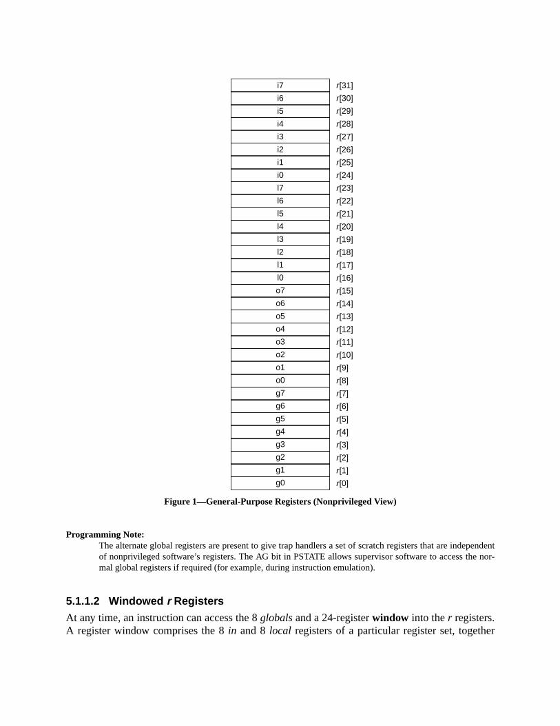
pendentnor-
er
Figure 1—General-Purpose Registers (Nonprivileged View)
Programming Note:The alternate global registers are present to give trap handlers a set of scratch registers that are indeof nonprivileged software’s registers. The AG bit in PSTATE allows supervisor software to access themal global registers if required (for example, during instruction emulation).
5.1.1.2 Windowed r Registers
At any time, an instruction can access the 8globalsand a 24-registerwindow into ther registers.A register window comprises the 8in and 8local registers of a particular register set, togeth
i7 r[31]
i6 r[30]
i5 r[29]
i4 r[28]
i3 r[27]
i2 r[26]
i1 r[25]
i0 r[24]
r[23]
r[22]
r[21]
r[20]
r[19]
r[18]
r[17]
r[16]
r[15]
r[14]
r[13]
r[12]
r[11]
r[10]
r[9]
r[8]
r[7]
r[6]
r[5]
r[4]
r[3]
r[2]
r[1]
r[0]
l7
l6
l5
l4
l3
l2
l1
l0
o7
o6
o5
o4
o3
o2
o1
o0
g7
g6
g5
g4
g3
g2
g1
g0

indow
ese
with the 8in registers of an adjacent register set, which are addressable from the current wasout registers. See figure 2 and table 6.
Figure 2—Three Overlapping Windows and the Eight Global Registers
The number of windows or register sets,NWINDOWS, is implementation-dependent and rangfrom 3 to 32 (impl. dep. #2). The total number ofr registers in a given implementation is 8 (for th
Window (CWP – 1)
r[31]
r[24]
ins..
r[23]
r[16]
locals..
r[15]
r[ 8]
outs..
Window (CWP )
r[31]
r[24]
ins..
r[23]
r[16]
locals..
r[15]
r[ 8]
outs..
Window (CWP + 1)
r[31]
r[24]
ins..
r[23]
r[16]
locals..
r[15]
r[ 8]
outs..
r[ 7]
r[ 1]
globals..
r[ 0] 0
63 0

the
er.ction.via
ver-
ss-
nted
called
ber of
e thatexe-
SAVEAN-
globals), plus 8 (for the alternateglobals), plus the number of sets times 16 registers/set. Thus,minimum number ofr registers is 64 (3 sets plus the 16globalsand alternateglobals) and themaximum number is 528 (32 sets plus the 16globals and alternateglobals).
The current window into ther registers is given by the current window pointer (CWP) registThe CWP is decremented by the RESTORE instruction and incremented by the SAVE instruWindow overflow is detected via the CANSAVE register and window underflow is detectedthe CANRESTORE register, both of which are controlled by privileged software. A window oflow (underflow) condition causes a window spill (fill) trap.
5.1.1.3 Overlapping Windows
Each window shares itsins with one adjacent window and itsouts with another. Theouts of theCWP–1 (modulo NWINDOWS) window are addressable as theins of the current window, and theouts in the current window are theins of the CWP+1 (modulo NWINDOWS) window. Thelocalsare unique to each window.
An r register with addresso, where 8≤ o ≤ 15, refers to exactly the same register as (o+16) doesafter the CWP is incremented by 1 (modulo NWINDOWS). Likewise, a register with addrei,where 24≤ i ≤ 31, refers to exactly the same register as address (i −16) does after the CWP is decremented by 1 (modulo NWINDOWS). See figures 2 and 3.
Since CWP arithmetic is performed modulo NWINDOWS, the highest numbered implemewindow overlaps with window 0. Theouts of window NWINDOWS−1 are theins of window 0.Implemented windows must be numbered contiguously from 0 through NWINDOWS−1.
Programming Note:Since the procedure call instructions (CALL and JMPL) do not change the CWP, a procedure can bewithout changing the window. See H.1.2, “Leaf-Procedure Optimization.”
Because the windows overlap, the number of windows available to software is one less than the numimplemented windows, or NWINDOWS−1. When the register file is full, theouts of the newest window arethe ins of the oldest window, which still contains valid data.
The local andout registers of a register window are guaranteed to contain either zeroes or an old valubelongs to the current context upon reentering the window through a SAVE instruction. If a programcutes a RESTORE followed by a SAVE, the resulting window’slocals andouts may not be valid after theSAVE, since a trap may have occurred between the RESTORE and the SAVE. However, if theclean_windowprotocol is being used, system software must guarantee that registers in the current window after awill always contain only zeroes or valid data from that context. See 5.2.10.6, “Clean Windows (CLEWIN) Register.”
Table 6—Window Addressing
Windowed Register Address r Register Address
in[0] – in[7] r[24] – r[31]
local[0] – local[7] r[16] – r[23]
out[0] – out[7] r[ 8] – r[15]
global[0] – global[7] r[ 0] – r[ 7]

isters
Subsection 6.4, “Register Window Management,” describes how the windowed integer regare managed.Figure 3—The Windowedr Registers for NWINDOWS = 8
5.1.2 Special r Registers
The usage of two of ther registers is fixed, in whole or in part, by the architecture:
— The value ofr[0] is always zero; writes to it have no program-visible effect.
CWP = 0(current window pointer)
w1 outs
w2 outs
w3 outs
w4 outs
w5 outs
w6 outs
w7 outs
w0 outsw0 locals
w0 ins
w1 locals
w1 ins
w3 locals
w3 ins
w5 locals
w5 ins
w4 locals
w4 ins
w6 locals
w2 locals
w2 ins
w7 locals
w7 ins
RESTORESAVE
w6 ins
(Overlap)
OTHERWIN = 2
CANRESTORE = 1
CANSAVE = 3
CANSAVE + CANRESTORE + OTHERWIN = NWINDOWS – 2
The current window (window 0) and the overlap window (window 4) account for the two windowsin the right-hand side of the equation. The “overlap window” is the window that must remainunused because its ins and outs overlap two other valid windows.
32-
ned
,
he 32-tate
holdso bits
on isnsferelayts to
fcc,
— The CALL instruction writes its own address into registerr[15] (out register 7).
5.1.2.1 Register-Pair Operands
LDD, LDDA, STD, and STDA instructions access a pair of words in adjacentr registers andrequire even-odd register alignment. The least-significant bit of anr register number in theseinstructions is reserved, and should be supplied as zero by software.
When ther[0] – r[1] register pair is used as a destination in LDD or LDDA, onlyr[1] is modified.When ther[0] – r[1] register pair is used as a source in STD or STDA, a zero is written to thebit word at the lowest address and the least significant 32 bits ofr[1] are written to the 32-bit wordat the highest address (in big-endian mode).
An attempt to execute an LDD, LDDA, STD, or STDA instruction that refers to a misalig(odd) destination register number causes anillegal_instruction trap.
5.1.2.2 Register Usage
See H.1.1, “Registers,” for information about the conventional usage of ther registers.
In figure 3, NWINDOWS = 8. The 8globals are not illustrated. CWP = 0, CANSAVE = 3OTHERWIN = 2, and CANRESTORE = 1. If the procedure using windoww0 executes aRESTORE, windoww7becomes the current window. If the procedure using windoww0executesa SAVE, windoww1 becomes the current window.
5.1.3 IU Control/Status Registers
The nonprivileged IU control/status registers include the program counters (PC and nPC), tbit multiply/divide (Y) register (and possibly optional) implementation-dependent Ancillary SRegisters (ASRs) (impl. dep. #8).
5.1.3.1 Program Counters (PC, nPC)
The PC contains the address of the instruction currently being executed by the IU. The nPCthe address of the next instruction to be executed, if a trap does not occur. The low-order twof PC and nPC always contain zero.
For a delayed control transfer, the instruction that immediately follows the transfer instructiknown as the delay instruction. This delay instruction is executed (unless the control trainstruction annuls it) before control is transferred to the target. During execution of the dinstruction, the nPC points to the target of the control transfer instruction, while the PC pointhe delay instruction. See Chapter 6, “Instructions.”
The PC is used implicitly as a destination register by CALL, Bicc, BPcc, BPr, FBfcc, FBPJMPL, and RETURN instructions. It can be read directly by an RDPC instruction.
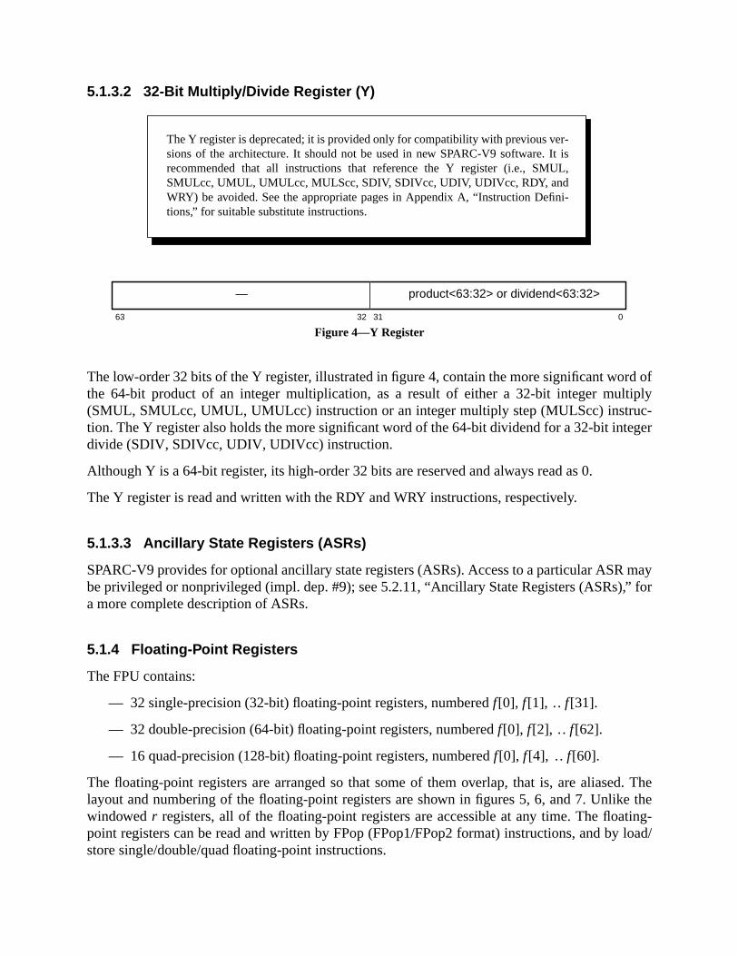
d ofiply-
eger
may,” for
d. Thee theting-load/
5.1.3.2 32-Bit Multiply/Divide Register (Y)
Figure 4—Y Register
The low-order 32 bits of the Y register, illustrated in figure 4, contain the more significant worthe 64-bit product of an integer multiplication, as a result of either a 32-bit integer mult(SMUL, SMULcc, UMUL, UMULcc) instruction or an integer multiply step (MULScc) instruction. The Y register also holds the more significant word of the 64-bit dividend for a 32-bit intdivide (SDIV, SDIVcc, UDIV, UDIVcc) instruction.
Although Y is a 64-bit register, its high-order 32 bits are reserved and always read as 0.
The Y register is read and written with the RDY and WRY instructions, respectively.
5.1.3.3 Ancillary State Registers (ASRs)
SPARC-V9 provides for optional ancillary state registers (ASRs). Access to a particular ASRbe privileged or nonprivileged (impl. dep. #9); see 5.2.11, “Ancillary State Registers (ASRs)a more complete description of ASRs.
5.1.4 Floating-Point Registers
The FPU contains:
— 32 single-precision (32-bit) floating-point registers, numberedf[0], f [1], .. f[31].
— 32 double-precision (64-bit) floating-point registers, numberedf[0], f[2], .. f[62].
— 16 quad-precision (128-bit) floating-point registers, numberedf[0], f [4], .. f[60].
The floating-point registers are arranged so that some of them overlap, that is, are aliaselayout and numbering of the floating-point registers are shown in figures 5, 6, and 7. Unlikwindowedr registers, all of the floating-point registers are accessible at any time. The floapoint registers can be read and written by FPop (FPop1/FPop2 format) instructions, and bystore single/double/quad floating-point instructions.
The Y register is deprecated; it is provided only for compatibility with previous ver-sions of the architecture. It should not be used in new SPARC-V9 software. It isrecommended that all instructions that reference the Y register (i.e., SMUL,SMULcc, UMUL, UMULcc, MULScc, SDIV, SDIVcc, UDIV, UDIVcc, RDY, andWRY) be avoided. See the appropriate pages in Appendix A, “Instruction Defini-tions,” for suitable substitute instructions.
63 032 31
— product<63:32> or dividend<63:32>
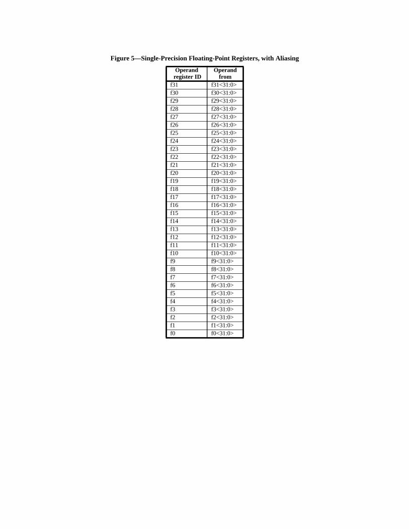
Figure 5—Single-Precision Floating-Point Registers, with Aliasing
Operand register ID
Operandfrom
f31 f31<31:0>f30 f30<31:0>f29 f29<31:0>f28 f28<31:0>f27 f27<31:0>f26 f26<31:0>f25 f25<31:0>f24 f24<31:0>f23 f23<31:0>f22 f22<31:0>f21 f21<31:0>f20 f20<31:0>f19 f19<31:0>f18 f18<31:0>f17 f17<31:0>f16 f16<31:0>f15 f15<31:0>f14 f14<31:0>f13 f13<31:0>f12 f12<31:0>f11 f11<31:0>f10 f10<31:0>f9 f9<31:0>f8 f8<31:0>f7 f7<31:0>f6 f6<31:0>f5 f5<31:0>f4 f4<31:0>f3 f3<31:0>f2 f2<31:0>f1 f1<31:0>f0 f0<31:0>

Figure 6—Double-Precision Floating-Point Registers, with Aliasing
Operand register ID
Operandfield
Fromregister
f62 <63:0> f62<63:0>f60 <63:0> f60<63:0>f58 <63:0> f58<63:0>f56 <63:0> f56<63:0>f54 <63:0> f54<63:0>f52 <63:0> f52<63:0>f50 <63:0> f50<63:0>f48 <63:0> f48<63:0>f46 <63:0> f46<63:0>f44 <63:0> f44<63:0>f42 <63:0> f42<63:0>f40 <63:0> f40<63:0>f38 <63:0> f38<63:0>f36 <63:0> f36<63:0>f34 <63:0> f34<63:0>f32 <63:0> f32<63:0>
f30<31:0> f31<31:0><63:32> f30<31:0>
f28<31:0> f29<31:0><63:32> f28<31:0>
f26<31:0> f27<31:0><63:32> f26<31:0>
f24<31:0> f25<31:0><63:32> f24<31:0>
f22<31:0> f23<31:0><63:32> f22<31:0>
f20<31:0> f21<31:0><63:32> f20<31:0>
f18<31:0> f19<31:0><63:32> f18<31:0>
f16<31:0> f17<31:0><63:32> f16<31:0>
f14<31:0> f15<31:0><63:32> f14<31:0>
f12<31:0> f13<31:0><63:32> f12<31:0>
f10<31:0> f11<31:0><63:32> f10<31:0>
f8<31:0> f9<31:0><63:32> f8<31:0>
f6<31:0> f7<31:0><63:32> f6<31:0>
f4<31:0> f5<31:0><63:32> f4<31:0>
f2<31:0> f3<31:0><63:32> f2<31:0>
f0<31:0> f1<31:0><63:32> f0<31:0>
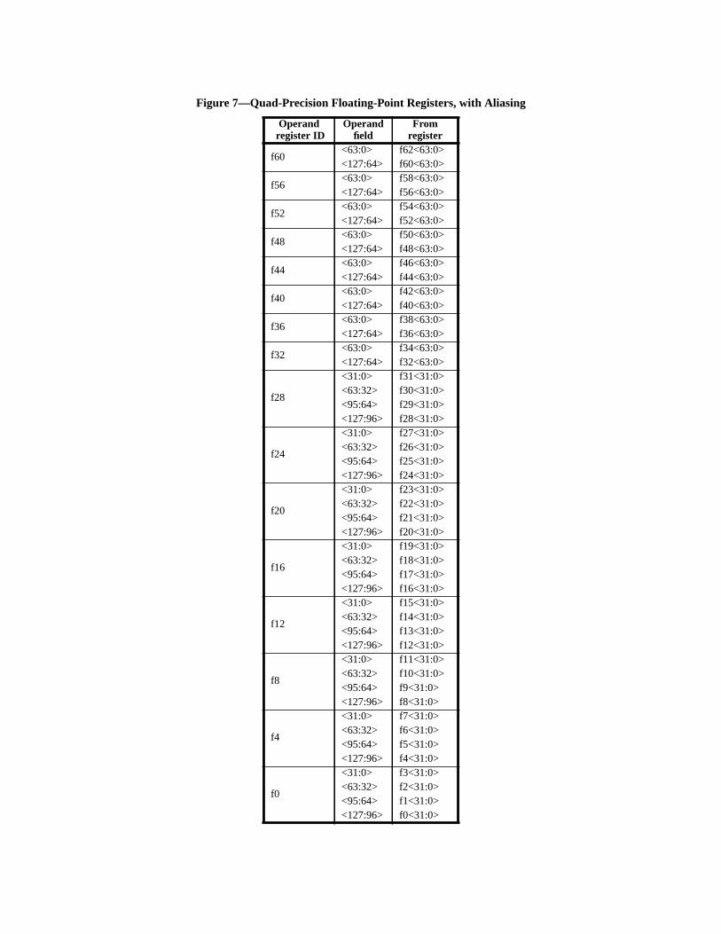
Figure 7—Quad-Precision Floating-Point Registers, with Aliasing
Operand register ID
Operandfield
Fromregister
f60<63:0> f62<63:0><127:64> f60<63:0>
f56<63:0> f58<63:0><127:64> f56<63:0>
f52<63:0> f54<63:0><127:64> f52<63:0>
f48<63:0> f50<63:0><127:64> f48<63:0>
f44<63:0> f46<63:0><127:64> f44<63:0>
f40<63:0> f42<63:0><127:64> f40<63:0>
f36<63:0> f38<63:0><127:64> f36<63:0>
f32<63:0> f34<63:0><127:64> f32<63:0>
f28
<31:0> f31<31:0><63:32> f30<31:0><95:64> f29<31:0><127:96> f28<31:0>
f24
<31:0> f27<31:0><63:32> f26<31:0><95:64> f25<31:0><127:96> f24<31:0>
f20
<31:0> f23<31:0><63:32> f22<31:0><95:64> f21<31:0><127:96> f20<31:0>
f16
<31:0> f19<31:0><63:32> f18<31:0><95:64> f17<31:0><127:96> f16<31:0>
f12
<31:0> f15<31:0><63:32> f14<31:0><95:64> f13<31:0><127:96> f12<31:0>
f8
<31:0> f11<31:0><63:32> f10<31:0><95:64> f9<31:0><127:96> f8<31:0>
f4
<31:0> f7<31:0><63:32> f6<31:0><95:64> f5<31:0><127:96> f4<31:0>
f0
<31:0> f3<31:0><63:32> f2<31:0><95:64> f1<31:0><127:96> f0<31:0>

regis-led:
float-
to beenta-
res an
n, 16file,
res of
moryctions.
erand
5.1.4.1 Floating-Point Register Number Encoding
Register numbers for single, double, and quad registers are encoded differently in the 5-bitter number field in a floating-point instruction. If the bits in a register number field are labeb<4>..b<0> (where b<4> is the most-significant bit of the register number), the encoding ofing-point register numbers into 5-bit instruction fields is as given in table 7.
Compatibility Note:In SPARC-V8, bit 0 of double and quad register numbers encoded in instruction fields was requiredzero. Therefore, all SPARC-V8 floating-point instructions can run unchanged on a SPARC-V9 implemtion using the encoding in table 7.
5.1.4.2 Double and Quad Floating-Point Operands
A single f register can hold one single-precision operand, a double-precision operand requialigned pair off registers, and a quad-precision operand requires an aligned quadruple off regis-ters. At a given time, the floating-point registers can hold a maximum of 32 single-precisiodouble-precision, or 8 quad-precision values in the lower half of the floating-point registerplus an additional 16 double-precision or 8 quad-precision values in the upper half, or mixtuthe three sizes.
Programming Note:Data to be loaded into a floating-point double or quad register that is not doubleword-aligned in memust be loaded into the lower 16 double registers (8 quad registers) using single-precision LDF instruIf desired, it can then be copied into the upper 16 double registers (8 quad registers).
An attempt to execute an instruction that refers to a misaligned floating-point register op(that is, a quad-precision operand in a register whose 6-bit register number is not 0mod 4) shallcause anfp_exception_other trap, with FSR.ftt = 6 (invalid_fp_register).
Programming Note:Given the encoding in table 7, it is impossible to specify a misaligned double-precision register.
5.1.5 Condition Codes Register (CCR)
Figure 8—Condition Codes Register
Table 7—Floating-Point Register Number Encoding
Registeroperand
type 6-bit register number
Encoding in a5-bit register fieldin an instruction
Single f.p. or32-bit integer
0 b<4> b<3> b<2> b<1> b<0> b<4> b<3> b<2> b<1> b<0>
Double f.p. or64-bit integer
b<5> b<4> b<3> b<2> b<1> 0 b<4> b<3> b<2> b<1> b<5>
Quad f.p. b<5> b<4> b<3> b<2> 0 0 b<4> b<3> b<2> 0 b<5>
7 4 03
xcc iccCCR
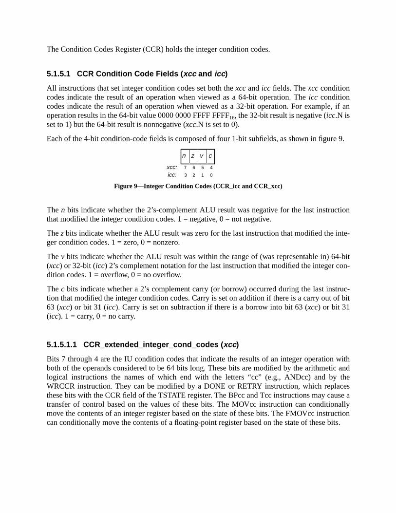
, if an
re 9.
tion
inte-
4-biton-
truc-of bit
withtic andthecesuse anallyructionbits.
The Condition Codes Register (CCR) holds the integer condition codes.
5.1.5.1 CCR Condition Code Fields ( xcc and icc )
All instructions that set integer condition codes set both thexccandicc fields. Thexccconditioncodes indicate the result of an operation when viewed as a 64-bit operation. Theicc conditioncodes indicate the result of an operation when viewed as a 32-bit operation. For exampleoperation results in the 64-bit value 0000 0000 FFFF FFFF16, the 32-bit result is negative (icc.N isset to 1) but the 64-bit result is nonnegative (xcc.N is set to 0).
Each of the 4-bit condition-code fields is composed of four 1-bit subfields, as shown in figu
Figure 9—Integer Condition Codes (CCR_icc and CCR_xcc)
Then bits indicate whether the 2’s-complement ALU result was negative for the last instructhat modified the integer condition codes. 1 = negative, 0 = not negative.
Thez bits indicate whether the ALU result was zero for the last instruction that modified theger condition codes. 1 = zero, 0 = nonzero.
Thev bits indicate whether the ALU result was within the range of (was representable in) 6(xcc) or 32-bit (icc) 2’s complement notation for the last instruction that modified the integer cdition codes. 1 = overflow, 0 = no overflow.
Thec bits indicate whether a 2’s complement carry (or borrow) occurred during the last instion that modified the integer condition codes. Carry is set on addition if there is a carry out63 (xcc) or bit 31 (icc). Carry is set on subtraction if there is a borrow into bit 63 (xcc) or bit 31(icc). 1 = carry, 0 = no carry.
5.1.5.1.1 CCR_extended_integer_cond_codes ( xcc )
Bits 7 through 4 are the IU condition codes that indicate the results of an integer operationboth of the operands considered to be 64 bits long. These bits are modified by the arithmelogical instructions the names of which end with the letters “cc” (e.g., ANDcc) and byWRCCR instruction. They can be modified by a DONE or RETRY instruction, which replathese bits with the CCR field of the TSTATE register. The BPcc and Tcc instructions may catransfer of control based on the values of these bits. The MOVcc instruction can conditiomove the contents of an integer register based on the state of these bits. The FMOVcc instcan conditionally move the contents of a floating-point register based on the state of these
7 5 4
0
6
13 2
xcc:icc:
cvn z
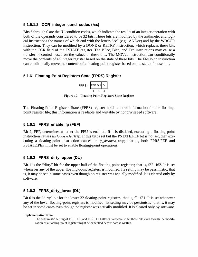
withd logi-CRbits
se anallyructionbits.
ting-
pointe-
d
et; thatnly by
vermayftware.
modifi-
5.1.5.1.2 CCR_integer_cond_codes ( icc )
Bits 3 through 0 are the IU condition codes, which indicate the results of an integer operationboth of the operands considered to be 32 bits. These bits are modified by the arithmetic ancal instructions the names of which end with the letters “cc” (e.g., ANDcc) and by the WRCinstruction. They can be modified by a DONE or RETRY instruction, which replaces thesewith the CCR field of the TSTATE register. The BPcc, Bicc, and Tcc instructions may cautransfer of control based on the values of these bits. The MOVcc instruction can conditiomove the contents of an integer register based on the state of these bits. The FMOVcc instcan conditionally move the contents of a floating-point register based on the state of these
5.1.6 Floating-Point Registers State (FPRS) Register
Figure 10—Floating-Point Registers State Register
The Floating-Point Registers State (FPRS) register holds control information for the floapoint register file; this information is readable and writable by nonprivileged software.
5.1.6.1 FPRS_enable_fp (FEF)
Bit 2, FEF, determines whether the FPU is enabled. If it is disabled, executing a floating-instruction causes anfp_disabled trap. If this bit is set but the PSTATE.PEF bit is not set, then excuting a floating-point instruction causes anfp_disabled trap; that is, both FPRS.FEF anPSTATE.PEF must be set to enable floating-point operations.
5.1.6.2 FPRS_dirty_upper (DU)
Bit 1 is the “dirty” bit for the upper half of the floating-point registers; that is, f32..f62. It is swhenever any of the upper floating-point registers is modified. Its setting may be pessimisticis, it may be set in some cases even though no register was actually modified. It is cleared osoftware.
5.1.6.3 FPRS_dirty_lower (DL)
Bit 0 is the “dirty” bit for the lower 32 floating-point registers; that is, f0..f31. It is set wheneany of the lower floating-point registers is modified. Its setting may be pessimistic; that is, itbe set in some cases even though no register was actually modified. It is cleared only by so
Implementation Note:The pessimistic setting of FPRS.DL and FPRS.DU allows hardware to set these bits even though thecation of a floating-point register might be cancelled before data is written.
012
DLFEF DUFPRS

. Theits of
se bitse bits,
areeec-andtruc-
gis-
5.1.7 Floating-Point State Register (FSR)
The FSR register fields, illustrated in figure 11, contain FPU mode and status informationlower 32 bits of the FSR are read and written by the STFSR and LDFSR instructions; all 64 bthe FSR are read and written by the STXFSR and LDXFSR instructions, respectively. Thever, ftt,andreserved fields are not modified by LDFSR or LDXFSR.
Figure 11—FSR Fields
Bits 63..38, 29..28, 21..20, and 12 are reserved. When read by an STXFSR instruction, theshall read as zero. Software should only issue LDXFSR instructions with zero values in thesunless the values of these bits are exactly those derived from a previous STFSR.
Subsections 5.1.7.1 through 5.1.7.10.5 describe the remaining fields in the FSR.
5.1.7.1 FSR_fp_condition_codes ( fcc0 , fcc1 , fcc2 , fcc3 )
There are four sets of floating-point condition code fields, labeledfcc0, fcc1, fcc2, andfcc3.
Compatibility Note:SPARC-V9’sfcc0 is the same as SPARC-V8’sfcc.
The fcc0field consists of bits 11 and 10 of the FSR,fcc1consists of bits 33 and 32,fcc2consistsof bits 35 and 34, and fcc3 consists of bits 37 and 36. Execution of a floating-point compinstruction (FCMP or FCMPE) updates one of thefccn fields in the FSR, as selected by thinstruction. Thefccn fields are read and written by STXFSR and LDXFSR instructions, resptively. Thefcc0field may also be read and written by STFSR and LDFSR, respectively. FBfccFBPfcc instructions base their control transfers on these fields. The MOVcc and FMOVcc instions can conditionally copy a register based on the state of these fields.
In table 8,frs1 andfrs2 correspond to the single, double, or quad values in the floating-point reters specified by a floating-point compare instruction’srs1 andrs2 fields. The question mark (‘?’)indicates an unordered relation, which is true if eitherfrs1 or frs2 is a signalling NaN or quiet NaN.If FCMP or FCMPE generates anfp_exception_ieee_754 exception, thenfccn is unchanged.
63 3235 34 3338 37
31 141923 13 12 11 5 4 091017 162730 29 28 22 21 20
36
fcc3 fcc2 fcc1—
RD — TEM NS — ver ftt qne — fcc0 aexc cexc

754-
t cantof the
e-
ating-itted
of thebit of
n 9.x,d in
5.1.7.2 FSR_rounding_direction (RD)
Bits 31 and 30 select the rounding direction for floating-point results according to IEEE Std1985. Table 9 shows the encodings.
5.1.7.3 FSR_trap_enable_mask (TEM)
Bits 27 through 23 are enable bits for each of the five IEEE-754 floating-point exceptions thabe indicated in the current_exception field (cexc). See figure 12 on page 67. If a floating-poinoperate instruction generates one or more exceptions and the TEM bit corresponding to anyexceptions is 1, anfp_exception_ieee_754 trap is caused. A TEM bit value of 0 prevents the corrsponding exception type from generating a trap.
5.1.7.4 FSR_nonstandard_fp (NS)
IMPL. DEP. #18: When set to 1, bit 22 causes the FPU to produce implementation-defined results thatmay not correspond to IEEE Std 754-1985.
For instance, to obtain higher performance, implementations may convert a subnormal flopoint operand or result to zero when FSR.NS is set. SPARC-V9 implementations are permbut not encouraged to deviate from IEEE 754 requirements when the nonstandard mode bitFSR is 1. For implementations in which no nonstandard floating-point mode exists, the NSthe FSR should always read as 0, and writes to it should be ignored.
See <Italic>Implementation Characteristics of Current SPARC-V9-based Products, Revisioa document available from SPARC International, for a description of how this field is useexisting implementations.
Table 8—Floating-Point Condition Codes (fccn) Fields of FSR
Content offccn Indicated relation
0 frs1 = frs2
1 frs1 < frs2
2 frs1 > frs2
3 frs1 ? frs2 (unordered)
Table 9—Rounding Direction (RD) Field of FSR
RD Round toward
0 Nearest (even if tie)
1 0
2 + ∞3 − ∞

ationller is, Revi-f this
n trapoint-
FSR
R) to
-
7” is
5.1.7.5 FSR_version ( ver)
IMPL. DEP. #19: Bits 19 through 17 identify one or more particular implementations of the FPU architec-ture.
For each SPARC-V9 IU implementation (as identified by its VER.impl field), there may be one ormore FPU implementations, or none. This field identifies the particular FPU implementpresent. Version number 7 is reserved to indicate that no hardware floating-point contropresent. See <Italic>Implementation Characteristics of Current SPARC-V9-based Productssion 9.x, a document available from SPARC International, for a description of the values ofield in existing implementations.
Thever field is read-only; it cannot be modified by the LDFSR and LDXFSR instructions.
5.1.7.6 FSR_floating-point_trap_type ( ftt )
Several conditions can cause a floating-point exception trap. When a floating-point exceptiooccurs,ftt (bits 16 through 14 of the FSR) identifies the cause of the exception, the “floating-ptrap type.” After a floating-point exception occurs, theftt field encodes the type of the floatingpoint exception until an STFSR or an FPop is executed.
The ftt field can be read by the STFSR and STXFSR instructions. The LDFSR and LDXinstructions do not affectftt.
Privileged software that handles floating-point traps must execute an STFSR (or STXFSdetermine the floating-point trap type. STFSR and STXFSR shall zeroftt after the store completeswithout error. If the store generates an error and does not complete,ftt shall remain unchanged.
Programming Note:Neither LDFSR nor LDXFSR can be used for this purpose, since both leaveftt unchanged. However, executing a nontrapping FPop such as “fmovs %f0,%f0 ” prior to returning to nonprivileged mode will zeroftt.Theftt remains valid until the next FPop instruction completes execution.
The ftt field encodes the floating-point trap type according to table 10. Note that the value “reserved for future expansion.
Table 10—Floating-Point Trap Type (ftt) Field of FSR
ftt Trap type
0 None
1 IEEE_754_exception
2 unfinished_FPop
3 unimplemented_FPop
4 sequence_error
5 hardware_error
6 invalid_fp_register
7 —
ofs. In
regis-
nalled,
sing
n-r
m-
le to. In the
ded
e-
The sequence_error and hardware_error trap types are unlikely to arise in the normal coursecomputation. They are essentially unrecoverable from the point of view of user applicationcontrast,IEEE_754_exception, unfinished_FPop, andunimplemented_FPop will likely arise occasion-ally in the normal course of computation and must be recoverable by system software.
When a floating-point trap occurs, the following results are observed by user software:
(1) The value ofaexc is unchanged.
(2) The value ofcexcis unchanged, except that for anIEEE_754_exception a bit correspondingto the trapping exception is set. Theunfinished_FPop, unimplemented_FPop, sequence_error,andinvalid_fp_register floating-point trap types do not affectcexc.
(3) The source registers are unchanged (usually implemented by leaving the destinationters unchanged).
(4) The value offccn is unchanged.
The foregoing describes the result seen by a user trap handler if an IEEE exception is sigeither immediately from anIEEE_754_exception or after recovery from anunfinished_FPop orunimplemented_FPop. In either case,cexcas seen by the trap handler reflects the exception cauthe trap.
In the cases ofunfinished_FPop andunimplemented_FPop exceptions that do not subsequently geerate IEEE traps, the recovery software should definecexc, aexc, and the destination registers ofccs, as appropriate.
5.1.7.6.1 ftt = IEEE_754_exception
The IEEE_754_exception floating-point trap type indicates that a floating-point exception conforing to IEEE Std 754-1985 has occurred. The exception type is encoded in thecexcfield. Note thataexc, thefccs, and the destinationf register are not affected by anIEEE_754_exception trap.
5.1.7.6.2 ftt = unfinished_FPop
Theunfinished_FPop floating-point trap type indicates that an implementation’s FPU was unabgenerate correct results, or that exceptions as defined by IEEE Std 754-1985 have occurredlatter case, thecexc field is unchanged.
5.1.7.6.3 ftt = unimplemented_FPop
Theunimplemented_FPop floating-point trap type indicates that an implementation’s FPU decoan FPop that it does not implement. In this case, thecexc field is unchanged.
Programming Note:For theunfinished_FPop andunimplemented_FPop floating-point traps, software should emulate or reexcute the exception-causing instruction and update the FSR, destinationf register(s), andfccs.

the
men-
ble toee, the
DPR
con-.
rnal
te to
; thatn
ter athat
5.1.7.6.4 ftt = sequence_error
Thesequence_error floating-point trap type indicates one of three abnormal error conditions inFPU, all caused by erroneous supervisor software:
— An attempt was made to read the floating-point deferred-trap queue (FQ) on an impletation without an FQ.
Implementation Note:IMPL. DEP #25: On implementations without a floating-point queue, an attempt to read the fq withan RDPR instruction shall cause either an illegal_instruction exception or an fp_exception_otherexception with FSR.ftt set to 4 (sequence_error).
— An attempt was made to execute a floating-point instruction when the FPU was unaaccept one. This type ofsequence_error arises from a logic error in supervisor softwarthat has caused a previous floating-point trap to be incompletely serviced (for examplfloating-point queue was not emptied after a previous floating-point exception).
— An attempt was made to read the floating-point deferred-trap queue (FQ) with a Rinstruction when the FQ was empty; that is, when FSR.qne= 0. Note that generation ofsequence_error is recommended but not required in this case.
Programming Note:If a sequence_error floating-point exception occurs while executing user code due to any of the aboveditions, it may not be possible to recover sufficient state to continue execution of the user application
5.1.7.6.5 ftt = hardware_error
Thehardware_error floating-point trap type indicates that the FPU detected a catastrophic inteerror, such as an illegal state or a parity error on anf register access.
Programming Note:If a hardware_error occurs while executing user code, it may not be possible to recover sufficient stacontinue execution of the user application.
5.1.7.6.6 ftt = invalid_fp_register
The invalid_fp_register trap indicates that one (or more) operands of an FPop are misalignedis, a quad-precision register number is not 0mod 4. An implementation shall generate afp_exception_other trap with FSR.ftt = invalid_fp_register in this case.
5.1.7.7 FSR_FQ_not_empty ( qne)
Bit 13 indicates whether the optional floating-point deferred-trap queue (FQ) is empty afdeferred floating-point exception trap or after a read privileged register (RDPR) instructionreads the queue has been executed. Ifqne= 0, the queue is empty; ifqne= 1, the queue is notempty.

FSR
ns zero
tions, the
accu-
ed byespond-
ution
n
s
defini-
The qne bit can be read by the STFSR and STXFSR instructions. The LDFSR and LDXinstructions do not affectqne. However, executing successive “RDPR %fpq” instructions will(eventually) cause the FQ to become empty (qne= 0). If an implementation does not provide aFQ, this bit shall read as zero. Supervisor software must arrange for this bit to always read ato user-mode software.
5.1.7.8 FSR_accrued_exception ( aexc)
Bits 9 through 5 accumulate IEEE_754 floating-point exceptions while floating-point exceptraps are disabled using the TEM field. See figure 13 on page 68. After an FPop completeTEM andcexcfields are logically ANDed together. If the result is nonzero,aexcis left unchangedand anfp_exception_ieee_754 trap is generated; otherwise, the newcexcfield is ORed into theaexcfield and no trap is generated. Thus, while (and only while) traps are masked, exceptions aremulated in theaexc field.
5.1.7.9 FSR_current_exception ( cexc )
Bits 4 through 0 indicate that one or more IEEE_754 floating-point exceptions were generatthe most recently executed FPop instruction. The absence of an exception causes the corring bit to be cleared. See figure 14 on page 68.
Thecexcbits are set as described in 5.1.7.10, “Floating-Point Exception Fields,” by the execof an FPop that either does not cause a trap or causes anfp_exception_ieee_754 trap withFSR.ftt = IEEE_754_exception. An IEEE_754_exception that traps shall cause exactly one bit iFSR.cexc to be set, corresponding to the detected IEEE Std 754-1985 exception.
In the case of an overflow (underflow)IEEE_754_exception that doesnot trap (because neitherOFM (UFM) nor NXM is set), more than one bit incexcis set: such an overflow (underflow) setbothofc (ufc) andnxc. An overflow (underflow)IEEE_754_exception thatdoestrap (because OFM(UFM) or NXM or both are set) shall setofc (ufc), but notnxc.
If the execution of an FPop causes a trap other than anfp_exception_ieee_754 due to an IEEE Std754-1985 exception, FSR.cexc is left unchanged.
5.1.7.10 Floating-Point Exception Fields
The current and accrued exception fields and the trap enable mask assume the followingtions of the floating-point exception conditions (per IEEE Std 754-1985):
Figure 12—Trap Enable Mask (TEM) Fields of FSR
24 2327 26 25
NVM OFM UFM DZM NXM
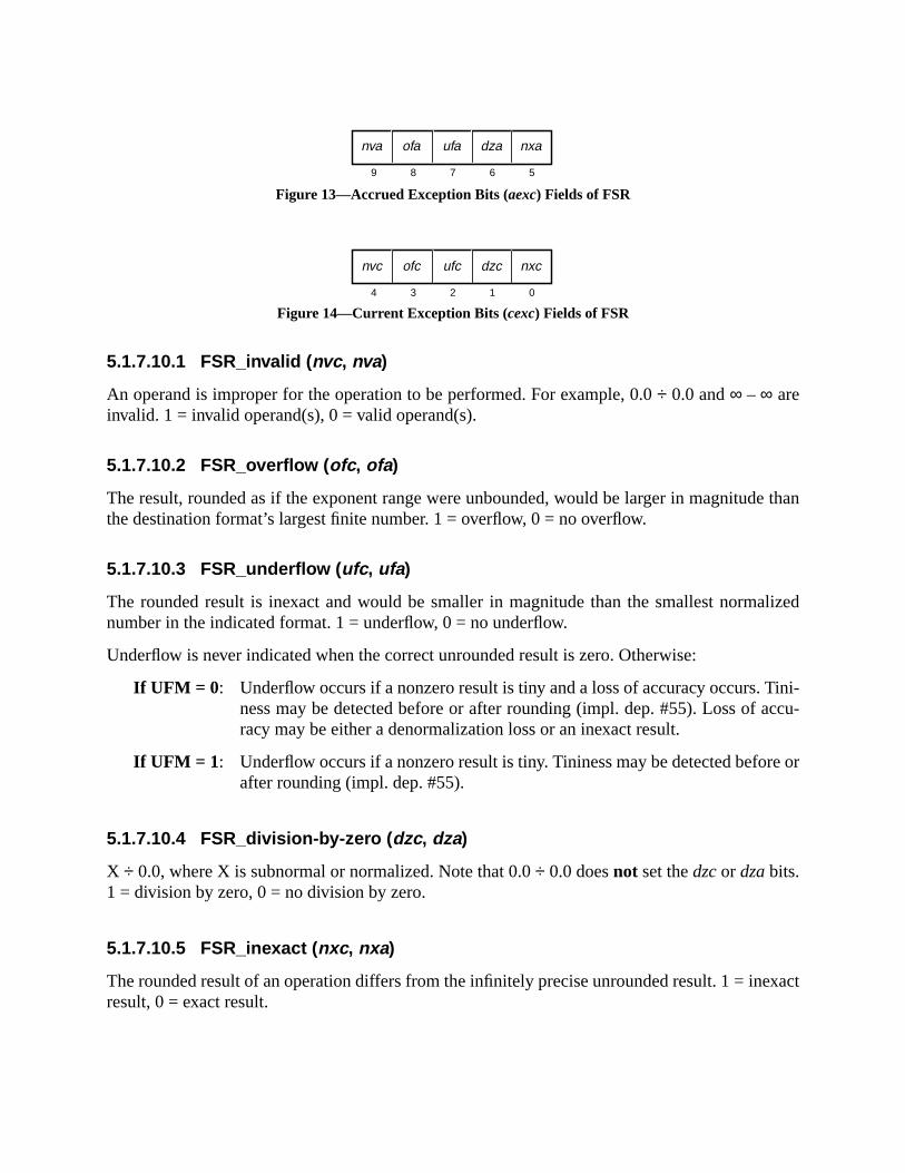
e than
alized
ini-ccu-
re or
exact
Figure 13—Accrued Exception Bits (aexc) Fields of FSR
Figure 14—Current Exception Bits (cexc) Fields of FSR
5.1.7.10.1 FSR_invalid ( nvc , nva)
An operand is improper for the operation to be performed. For example, 0.0÷ 0.0 and∞ – ∞ areinvalid. 1 = invalid operand(s), 0 = valid operand(s).
5.1.7.10.2 FSR_overflow ( ofc , ofa)
The result, rounded as if the exponent range were unbounded, would be larger in magnitudthe destination format’s largest finite number. 1 = overflow, 0 = no overflow.
5.1.7.10.3 FSR_underflow ( ufc , ufa)
The rounded result is inexact and would be smaller in magnitude than the smallest normnumber in the indicated format. 1 = underflow, 0 = no underflow.
Underflow is never indicated when the correct unrounded result is zero. Otherwise:
If UFM = 0 : Underflow occurs if a nonzero result is tiny and a loss of accuracy occurs. Tness may be detected before or after rounding (impl. dep. #55). Loss of aracy may be either a denormalization loss or an inexact result.
If UFM = 1 : Underflow occurs if a nonzero result is tiny. Tininess may be detected befoafter rounding (impl. dep. #55).
5.1.7.10.4 FSR_division-by-zero ( dzc, dza)
X ÷ 0.0, where X is subnormal or normalized. Note that 0.0÷ 0.0 doesnot set thedzcor dzabits.1 = division by zero, 0 = no division by zero.
5.1.7.10.5 FSR_inexact ( nxc , nxa)
The rounded result of an operation differs from the infinitely precise unrounded result. 1 = inresult, 0 = exact result.
6 59 8 7
nva ofa ufa dza nxa
1 04 3 2
nvc ofc ufc dzc nxc

5.
value
ey an
ularlue
the
ternatereSIs.0, a
” for
5.1.7.11 FSR Conformance
IMPL. DEP. #22: An implementation may choose to implement the TEM, cexc, and aexc fields in hardwarein either of two ways (both of which comply with IEEE Std 754-1985):
(1) Implement all three fields conformant to IEEE Std 754-1985.
(2) Implement the NXM,nxa, andnxcbits of these fields conformant to IEEE Std 754-198Implement each of the remaining bits in the three fields either
(a) Conformant to IEEE Std 754-1985, or
(b) As a state bit that may be set by software that calculates the IEEE Std 754-1985of the bit. For any bit implemented as a state bit:
[1] The IEEE exception corresponding to the state bit mustalwayscause an exception(specifically, anunfinished_FPop exception). During exception processing in thtrap handler, the bit in the state field can be written to the appropriate value bLDFSR or LDXFSR instruction.
[2] The state bit must be implemented in such a way that if it is written to a particvalue by an LDFSR or LDXFSR instruction, it will be read back as the same vaby a subsequent STFSR or STXFSR.
Programming Note:Software must be capable of simulating the operation of the FPU in order to handleunimplemented_FPop, unfinished_FPop, andIEEE_754_exception floating-point trap types properly. Thus, auser application program always sees an FSR that is fully compliant with IEEE Std 754-1985.
5.1.8 Address Space Identifier Register (ASI)
Figure 15—ASI Register
The ASI register specifies the address space identifier to be used for load and store alinstructions that use the “rs1 + simm13” addressing form. Nonprivileged (user-mode) softwamay write any value into the ASI register; however, values with bit 7 = 0 indicate restricted AWhen a nonprivileged instruction makes an access that uses an ASI with bit 7 =privileged_action exception is generated. See 6.3.1.3, “Address Space Identifiers (ASIs),details.
5.1.9 TICK Register (TICK)
Figure 16—TICK Register
7 0
ASI
063 62
TICK NPT counter

ofisterr thethe
PTister
one. Thember ofunts of
curacyread
ode;and
of the
Thecounterfield of the TICK register is a 63-bit counter that counts CPU clock cycles. Bit 63the TICK register is the Nonprivileged Trap (NPT) bit, which controls access to the TICK regby nonprivileged software. Privileged software can always read the TICK register with eitheRDPR or RDTICK instruction. Privileged software can always write the TICK register withWRPR instruction; there is no WRTICK instruction.
Nonprivileged software can read the TICK register using the RDTICK instruction; TICK.Nmust be 0. When TICK.NPT = 1, an attempt by nonprivileged software to read the TICK regcauses aprivileged_action exception. Nonprivileged software cannot write the TICK register.
TICK.NPT is set to 1 by a power-on reset trap. The value of TICK.counteris undefined after apower-on reset trap.
After the TICK register is written, reading the TICK register returns a value incremented (byor more) from the last value written, rather than from some previous value of the counternumber of counts between a write and a subsequent read need not accurately reflect the nuprocessor cycles between the write and the read. Software may only rely on read-to-read cothe TICK register for accurate timing, not on write-to-read counts.
IMPL. DEP. #105: The difference between the values read from the TICK register on two reads shouldreflect the number of processor cycles executed between the reads. If an accurate count cannot always bereturned, any inaccuracy should be small, bounded, and documented. An implementation may implementfewer than 63 bits in TICK.counter; however, the counter as implemented must be able to count for at least10 years without overflowing. Any upper bits not implemented must read as zero.
Programming Note:TICK.NPT may be used by a secure operating system to control access by user software to high-actiming information. The operation of the timer might be emulated by the trap handler, which couldTICK.counter and “fuzz” the value to lower accuracy.
5.2 Privileged Registers
The registers described in this subsection are visible only to software running in privileged mthat is, when PSTATE.PRIV = 1. Privileged registers are written using the WRPR instructionread using the RDPR instruction.
5.2.1 Processor State Register (PSTATE)
Figure 17—PSTATE Fields
The PSTATE register holds the current state of the processor. There is only one instancePSTATE register. See Chapter 7, “Traps,” for more details.
4 0
PSTATE PEF AM PRIV IE AG
3 2 16 5
MM RED
7
TLECLE
9 8
PID0PID1
11 10
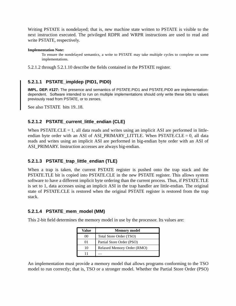
thed and
some
ttle-taI of
d thetem.TLEiginaltrap
TSOPSO)
Writing PSTATE is nondelayed; that is, new machine state written to PSTATE is visible tonext instruction executed. The privileged RDPR and WRPR instructions are used to reawrite PSTATE, respectively.
Implementation Note:To ensure the nondelayed semantics, a write to PSTATE may take multiple cycles to complete onimplementations.
5.2.1.2 through 5.2.1.10 describe the fields contained in the PSTATE register.
5.2.1.1 PSTATE_impldep (PID1, PID0)
IMPL. DEP. #127: The presence and semantics of PSTATE.PID1 and PSTATE.PID0 are implementation-dependent. Software intended to run on multiple implementations should only write these bits to valuespreviously read from PSTATE, or to zeroes.
See also TSTATE bits 19..18.
5.2.1.2 PSTATE_current_little_endian (CLE)
When PSTATE.CLE = 1, all data reads and writes using an implicit ASI are performed in liendian byte order with an ASI of ASI_PRIMARY_LITTLE. When PSTATE.CLE = 0, all dareads and writes using an implicit ASI are performed in big-endian byte order with an ASASI_PRIMARY. Instruction accesses are always big-endian.
5.2.1.3 PSTATE_trap_little_endian (TLE)
When a trap is taken, the current PSTATE register is pushed onto the trap stack anPSTATE.TLE bit is copied into PSTATE.CLE in the new PSTATE register. This allows syssoftware to have a different implicit byte ordering than the current process. Thus, if PSTATEis set to 1, data accesses using an implicit ASI in the trap handler are little-endian. The orstate of PSTATE.CLE is restored when the original PSTATE register is restored from thestack.
5.2.1.4 PSTATE_mem_model (MM)
This 2-bit field determines the memory model in use by the processor. Its values are:
An implementation must provide a memory model that allows programs conforming to themodel to run correctly; that is, TSO or a stronger model. Whether the Partial Store Order (
Value Memory model
00 Total Store Order (TSO)
01 Partial Store Order (PSO)
10 Relaxed Memory Order (RMO)
11 —

ndent
tting
state.o setsby
and
ded thatnewPR in
nagee set.
der 32o-bit
L, andmen-trap
model or the Relaxed Memory Ordering (RMO) model is supported is implementation-depe(impl. dep. #113).
The current memory model is determined by the value of PSTATE.MM. The effect of sePSTATE.MM to an unsupported value is implementation-dependent (impl. dep. #119).
5.2.1.5 PSTATE_RED_state (RED)
When PSTATE.RED is set to 1, the processor is operating in RED (Reset, Error, and Debug)See 7.2.1, “RED_state.” The IU sets PSTATE.RED when any hardware reset occurs. It alsPSTATE.RED when a trap is taken while TL = (MAXTL – 1). Software can exit RED_stateone of two methods:
(1) Execute a DONE or RETRY instruction, which restores the stacked copy of PSTATEclears PSTATE.RED if it was 0 in the stacked copy.
(2) Write a 0 to PSTATE.RED with a WRPR instruction.
Programming Note:Changing PSTATE.RED may cause a change in address mapping on some systems. It is recommenwrites of PSTATE.RED be placed in the delay slot of a JMPL; the target of this JMPL should be in theaddress mapping. The JMPL sets the nPC, which becomes the PC for the instruction that folows the Wits delay slot. The effect of the WPR instruction is immediate.
5.2.1.6 PSTATE_enable_floating-point (PEF)
When set to 1, this bit enables the floating-point unit, which allows privileged software to mathe FPU. For the floating-point unit to be usable, both PSTATE.PEF and FPRS.FEF must bOtherwise, a floating-point instruction that tries to reference the FPU will cause anfp_disabledtrap.
5.2.1.7 PSTATE_address_mask (AM)
When PSTATE.AM = 1, both instruction and data addresses are interpreted as if the high-orbits were masked to zero before being presented to the MMU or memory system. Thirty-twapplication software must run with this bit set.
Branch target addresses (sent to the nPC) and addresses sent to registers by CALL, JMPRDPC instructions are always 64-bit values, but the value of the high-order 32-bits are impletation-dependent. Similarly, the value of the high-order 32-bits of TPC and TNPC after ataken while PSTATE.AM = 1 is implementation-dependent.
IMPL. DEP. #125: When PSTATE.AM = 1, the value of the high-order 32-bits of the PC transmitted to thespecified destination register(s) by CALL, JMLP, RDPC, and on a trap is implementation-dependent.
5.2.1.8 PSTATE_privileged_mode (PRIV)
When PSTATE.PRIV = 1, the processor is in privileged mode.

..7 asteger
oper-e thattrap
ple-
not
pt aninter-ies.
seman-other
5.2.1.9 PSTATE_interrupt_enable (IE)
When PSTATE.IE = 1, the processor can accept interrupts.
5.2.1.10 PSTATE_alternate_globals (AG)
When PSTATE.AG = 0, the processor interprets integer register numbers in the range 0referring to the normal global register set. When PSTATE.AG = 1, the processor interprets inregister numbers in the range 0..7 as referring to the alternate global register set.
5.2.2 Trap Level Register (TL)
Figure 18—Trap Level Register
The trap level register specifies the current trap level. TL = 0 is the normal (nontrap) level ofation. TL > 0 implies that one or more traps are being processed. The maximum valid valuthe TL register may contain is “MAXTL.” This is always equal to the number of supportedlevels beyond level 0. See Chapter 7, “Traps,” for more details about the TL register. An immentation shall support at least four levels of traps beyond level 0; that is, MAXTL shall be≥ 4.
IMPL. DEP. #101: How many additional trap levels, if any, past level 4 are supported is implementation-dependent.
The remainder of this subsection assumes that there are four trap levels beyond level 0.
Programming Note:Writing the TL register with awrpr %tl instruction does not alter any other machine state; that is, it isequivalent to taking or returning from a trap.
5.2.3 Processor Interrupt Level (PIL)
Figure 19—Processor Interrupt Level Register
The processor interrupt level (PIL) is the interrupt level above which the processor will acceinterrupt. Interrupt priorities are mapped such that interrupt level 2 has greater priority thanrupt level 1, and so on. See table 15 on page 103 for a list of exception and interrupt priorit
Compatibility Note:On SPARC-V8 processors, the level 15 interrupt is considered to be nonmaskable, so it has differenttics from other interrupt levels. SPARC-V9 processors do not treat level 15 interrupts differently from
2 0
TL TL
3 0
PIL PIL

t is
e arecur-
e. An
e arecur-
e. An
interrupt levels. See 7.6.2.4, “Externally Initiated Reset (XIR) Traps,” for a facility in SPARC-V9 thasimilar to a nonmaskable interrupt.
5.2.4 Trap Program Counter (TPC)
Figure 20—Trap Program Counter Register
The TPC register contains the program counter (PC) from the previous trap level. TherMAXTL instances of the TPC (impl. dep. #101), but only one is accessible at any time. Therent value in the TL register determines which instance of the TPC register is accessiblattempt to read or write the TPC register when TL = 0 shall cause anillegal_instruction exception.
5.2.5 Trap Next Program Counter (TNPC)
Figure 21—Trap Next Program Counter Register
The TNPC register is the next program counter (nPC) from the previous trap level. TherMAXTL instances of the TNPC (impl. dep. #101), but only one is accessible at any time. Therent value in the TL register determines which instance of the TNPC register is accessiblattempt to read or write the TNPC register when TL = 0 shall cause anillegal_instruction exception.
TPC1 PC from trap while TL = 0
2
00
63 1 0
TPC2 PC from trap while TL = 1 00
TPC3 PC from trap while TL = 2 00
TPC4 PC from trap while TL = 3 00
TNPC1 nPC from trap while TL = 0
2
00
63 1 0
TNPC2 nPC from trap while TL = 1 00
TNPC3 nPC from trap while TL = 2 00
TNPC4 nPC from trap while TL = 3 00

, ASI,f theeter-ister
t trapte Trappro-xcep-
at acessi-
5.2.6 Trap State (TSTATE)
Figure 22—Trap State Register
TSTATE contains the state from the previous trap level, comprising the contents of the CCRCWP, and PSTATE registers from the previous trap level. There are MAXTL instances oTSTATE register, but only one is accessible at a time. The current value in the TL register dmines which instance of TSTATE is accessible. An attempt to read or write the TSTATE regwhen TL = 0 causes anillegal_instruction exception.
TSTATE bits 19 and 18 are implementation-dependent.IMPL.DEP. #127: If PSTATE bit 11 (10) isimplemented, TSTATE bit 19 (18) shall be implemented and contain the state of PSTATE bit 11 (10) fromthe previous trap level. If PSTATE bit 11 (10) is not implemented, TSTATE bit 19 (18) shall read as zero.Software intended to run on multiple implementations should only write these bits to values previously readfrom PSTATE, or to zeroes.
5.2.7 Trap Type Register (TT)
Figure 23—Trap Type Register
The TT register normally contains the trap type of the trap that caused entry to the currenlevel. On a reset trap the TT field contains the trap type of the reset (see 7.2.1.1, “RED_staTable”), except when a watchdog (WDR) or externally initiated (XIR) reset occurs while thecessor is in error_state. When this occurs, the TT register will contain the trap type of the etion that caused entry into error_state.
There are MAXTL instances of the TT register (impl. dep. #101), but only one is accessibletime. The current value in the TL register determines which instance of the TT register is acble. An attempt to read or write the TT register when TL = 0 shall cause anillegal_instructionexception.
39 0
TSTATE1 CCR from TL = 0 CWP from TL = 0ASI from TL = 0 PSTATE from TL = 0— —
432 31 24 23 20 8 7 519
TSTATE2 CCR from TL = 1 CWP from TL = 1ASI from TL = 1 PSTATE from TL = 1— —
TSTATE3 CCR from TL = 2 CWP from TL = 2ASI from TL = 2 PSTATE from TL = 2— —
TSTATE4 CCR from TL = 3 CWP from TL = 3ASI from TL = 3 PSTATE from TL = 3— —
TT1 Trap type from trap while TL = 0
8 0
TT2 Trap type from trap while TL = 1
TT3 Trap type from trap while TL = 2
TT4 Trap type from trap while TL = 3
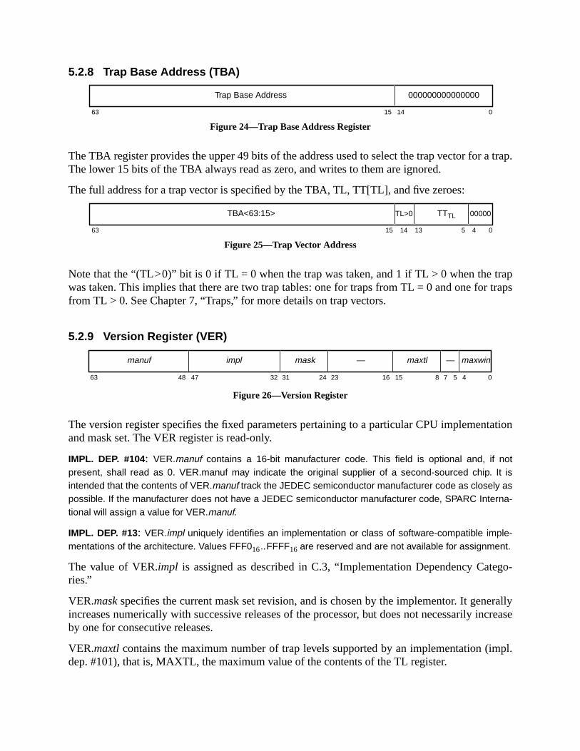
a trap.
aptraps
tation
ego-
erallyincrease
mpl.
5.2.8 Trap Base Address (TBA)
Figure 24—Trap Base Address Register
The TBA register provides the upper 49 bits of the address used to select the trap vector forThe lower 15 bits of the TBA always read as zero, and writes to them are ignored.
The full address for a trap vector is specified by the TBA, TL, TT[TL], and five zeroes:
Figure 25—Trap Vector Address
Note that the “(TL>0)” bit is 0 if TL = 0 when the trap was taken, and 1 if TL > 0 when the trwas taken. This implies that there are two trap tables: one for traps from TL = 0 and one forfrom TL > 0. See Chapter 7, “Traps,” for more details on trap vectors.
5.2.9 Version Register (VER)
Figure 26—Version Register
The version register specifies the fixed parameters pertaining to a particular CPU implemenand mask set. The VER register is read-only.
IMPL. DEP. #104: VER.manuf contains a 16-bit manufacturer code. This field is optional and, if notpresent, shall read as 0. VER.manuf may indicate the original supplier of a second-sourced chip. It isintended that the contents of VER.manuf track the JEDEC semiconductor manufacturer code as closely aspossible. If the manufacturer does not have a JEDEC semiconductor manufacturer code, SPARC Interna-tional will assign a value for VER.manuf.
IMPL. DEP. #13: VER.impl uniquely identifies an implementation or class of software-compatible imple-mentations of the architecture. Values FFF016..FFFF16 are reserved and are not available for assignment.
The value of VER.impl is assigned as described in C.3, “Implementation Dependency Catries.”
VER.maskspecifies the current mask set revision, and is chosen by the implementor. It genincreases numerically with successive releases of the processor, but does not necessarilyby one for consecutive releases.
VER.maxtlcontains the maximum number of trap levels supported by an implementation (idep. #101), that is, MAXTL, the maximum value of the contents of the TL register.
63 15 14 0
000000000000000Trap Base Address
63 15 14 0
TBA<63:15>
13 45
TL>0 TTTL 00000
63 48 47 24 23 16 15 8 7 05 432 31
maxwin—maxtl—maskimplmanuf
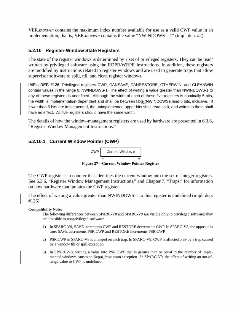
n an
read/sterst allow
n 6.3.6,
sters.tion
dep.
they
site is
aused
ple--
VER.maxwincontains the maximum index number available for use as a valid CWP value iimplementation; that is, VER.maxwin contains the value “NWINDOWS – 1” (impl. dep. #2).
5.2.10 Register-Window State Registers
The state of the register windows is determined by a set of privileged registers. They can bewritten by privileged software using the RDPR/WRPR instructions. In addition, these regiare modified by instructions related to register windows and are used to generate traps thasupervisor software to spill, fill, and clean register windows.
IMPL. DEP. #126: Privileged registers CWP, CANSAVE, CANRESTORE, OTHERWIN, and CLEANWINcontain values in the range 0..NWINDOWS-1. The effect of writing a value greater than NWINDOWS-1 toany of these registers is undefined. Although the width of each of these five registers is nominally 5 bits,the width is implementation-dependent and shall be between log2(NWINDOWS) and 5 bits, inclusive. Iffewer than 5 bits are implemented, the unimplemented upper bits shall read as 0, and writes to them shallhave no effect. All five registers should have the same width.
The details of how the window-management registers are used by hardware are presented i“Register Window Management Instructions.”
5.2.10.1 Current Window Pointer (CWP)
Figure 27—Current Window Pointer Register
The CWP register is a counter that identifies the current window into the set of integer regiSee 6.3.6, “Register Window Management Instructions,” and Chapter 7, “Traps,” for informaon how hardware manipulates the CWP register.
The effect of writing a value greater than NWINDOWS-1 to this register is undefined (impl.#126).
Compatibility Note:The following differences between SPARC-V8 and SPARC-V9 are visible only to privileged software;are invisible to nonprivileged software:
1) In SPARC-V9, SAVE increments CWP and RESTORE decrements CWP. In SPARC-V8, the oppotrue: SAVE decrements PSR.CWP and RESTORE increments PSR.CWP.
2) PSR.CWP in SPARC-V8 is changed on each trap. In SPARC-V9, CWP is affected only by a trap cby a window fill or spill exception.
3) In SPARC-V8, writing a value into PSR.CWP that is greater than or equal to the number of immented windows causes anillegal_instruction exception. In SPARC-V9, the effect of writing an out-ofrange value to CWP is undefined.
4 0
CWP Current Window #
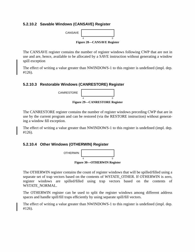
ot inindow
dep.
are innerat-
dep.
g azero,
of
dress
dep.
5.2.10.2 Savable Windows (CANSAVE) Register
Figure 28—CANSAVE Register
The CANSAVE register contains the number of register windows following CWP that are nuse and are, hence, available to be allocated by a SAVE instruction without generating a wspill exception
The effect of writing a value greater than NWINDOWS-1 to this register is undefined (impl.#126).
5.2.10.3 Restorable Windows (CANRESTORE) Register
Figure 29—CANRESTORE Register
The CANRESTORE register contains the number of register windows preceding CWP thatuse by the current program and can be restored (via the RESTORE instruction) without geing a window fill exception.
The effect of writing a value greater than NWINDOWS-1 to this register is undefined (impl.#126).
5.2.10.4 Other Windows (OTHERWIN) Register
Figure 30—OTHERWIN Register
The OTHERWIN register contains the count of register windows that will be spilled/filled usinseparate set of trap vectors based on the contents of WSTATE_OTHER. If OTHERWIN isregister windows are spilled/filled using trap vectors based on the contentsWSTATE_NORMAL.
The OTHERWIN register can be used to split the register windows among different adspaces and handle spill/fill traps efficiently by using separate spill/fill vectors.
The effect of writing a value greater than NWINDOWS-1 to this register is undefined (impl.#126).
4 0
CANSAVE
4 0
CANRESTORE
4 0
OTHERWIN
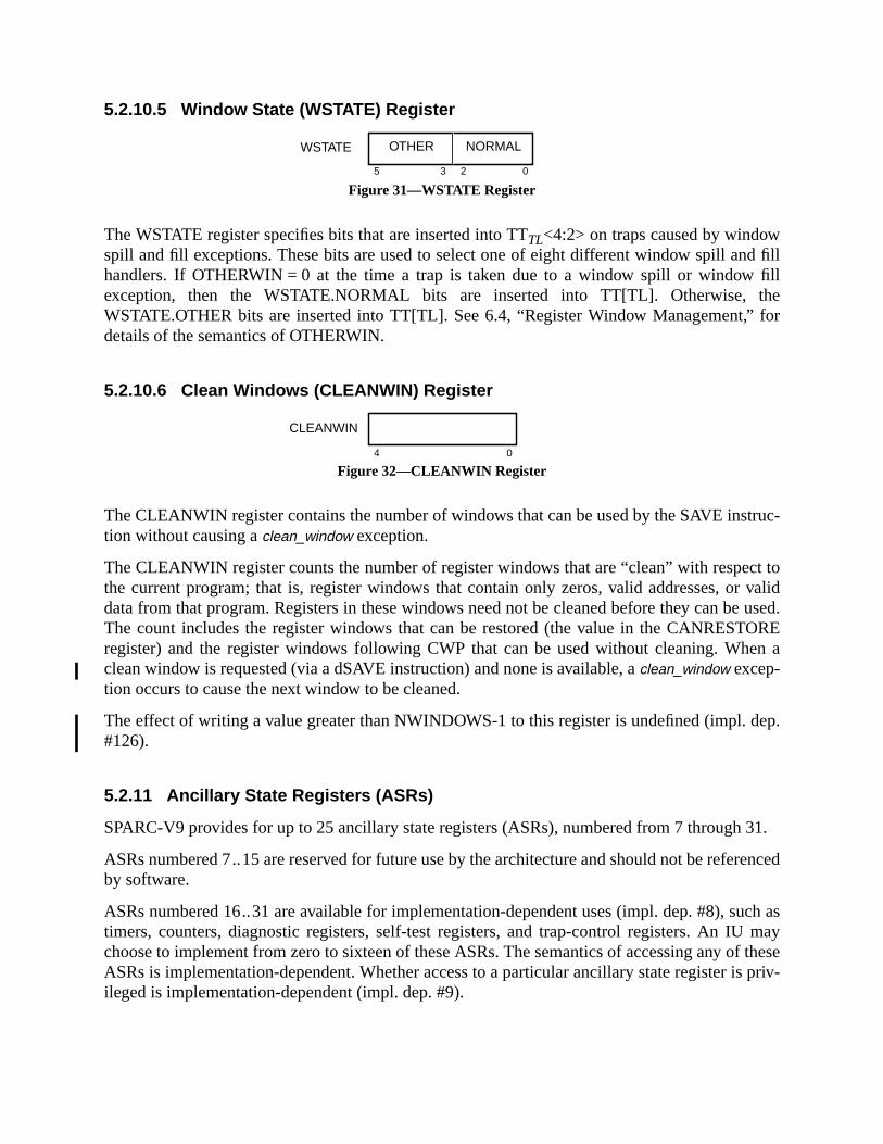
d fillfillhefor
truc-
ct tovalid
e used.OREen a
dep.
31.
renced
uch asmay
f theseis priv-
5.2.10.5 Window State (WSTATE) Register
Figure 31—WSTATE Register
The WSTATE register specifies bits that are inserted into TTTL<4:2> on traps caused by windowspill and fill exceptions. These bits are used to select one of eight different window spill anhandlers. If OTHERWIN = 0 at the time a trap is taken due to a window spill or windowexception, then the WSTATE.NORMAL bits are inserted into TT[TL]. Otherwise, tWSTATE.OTHER bits are inserted into TT[TL]. See 6.4, “Register Window Management,”details of the semantics of OTHERWIN.
5.2.10.6 Clean Windows (CLEANWIN) Register
Figure 32—CLEANWIN Register
The CLEANWIN register contains the number of windows that can be used by the SAVE instion without causing aclean_window exception.
The CLEANWIN register counts the number of register windows that are “clean” with respethe current program; that is, register windows that contain only zeros, valid addresses, ordata from that program. Registers in these windows need not be cleaned before they can bThe count includes the register windows that can be restored (the value in the CANRESTregister) and the register windows following CWP that can be used without cleaning. Whclean window is requested (via a dSAVE instruction) and none is available, aclean_window excep-tion occurs to cause the next window to be cleaned.
The effect of writing a value greater than NWINDOWS-1 to this register is undefined (impl.#126).
5.2.11 Ancillary State Registers (ASRs)
SPARC-V9 provides for up to 25 ancillary state registers (ASRs), numbered from 7 through
ASRs numbered 7..15 are reserved for future use by the architecture and should not be refeby software.
ASRs numbered 16..31 are available for implementation-dependent uses (impl. dep. #8), stimers, counters, diagnostic registers, self-test registers, and trap-control registers. An IUchoose to implement from zero to sixteen of these ASRs. The semantics of accessing any oASRs is implementation-dependent. Whether access to a particular ancillary state registerileged is implementation-dependent (impl. dep. #9).
WSTATE
05 3 2
OTHER NORMAL
4 0
CLEANWIN

SR
sum-
. In aalter-SR,
ausingany
risticsterna-es in
truc-
ns suf-raps,”oint
basedf such
An ASR is read and written with the RDASR and WRASR instructions, respectively. An RDAor WRASR instruction is privileged if the accessed register is privileged.
5.2.12 Floating-Point Deferred-Trap Queue (FQ)
If present in an implementation, the FQ contains sufficient state information to implement reable, deferred floating-point traps.
IMPL. DEP. #23: Floating-point traps may be precise or deferred. If deferred, a floating-point deferred-trapqueue (FQ) shall be present.
The FQ can be read with the read privileged register (RDPR) floating-point queue instructiongiven implementation, it may also be readable or writable via privileged load/store doublenate instructions (LDDA, STDA), or by read/write ancillary state register instructions (RDAWRASR).
IMPL. DEP. #24: The presence, contents of, and operations upon the FQ are implementation-dependent.
If an FQ is present, however, supervisor software must be able to deduce the exception-cinstruction’s opcode (opf), operands, and address from its FQ entry. This also must be true ofother pending floating-point operations in the queue. See <Italic>Implementation Characteof Current SPARC-V9-based Products, Revision 9.x, a document available from SPARC Intional, for a discussion of the formats and operation of implemented floating-point queuexisting SPARC-V9 implementations.
In implementations with a floating-point queue, an attempt to read the FQ with a RDPR instion when the FQ is empty (FSR.qne= 0) shall cause anfp_exception_other trap with FSR.ftt set to4 (sequence_error).In implementations without an FQ, theqne bit in the FSR is always 0.
IMPL. DEP. #25: In implementations without a floating-point queue, an attempt to read the FQ with anRDPR instruction shall cause either an illegal_instruction trap or an fp_exception_other trap with FSR.fttSET TO 4 (sequence_error).
5.2.13 IU Deferred-Trap Queue
An implementation may contain zero or more IU deferred-trap queues. Such a queue contaificient state to implement resumable deferred traps caused by the IU. See 7.3.2, “Deferred Tfor more information. Note that deferred floating-point traps are handled by the floating-pdeferred-trap queue. See <Italic>Implementation Characteristics of Current SPARC-V9-Products, Revision 9.x, a document available from SPARC International, for a discussion oqueues in existing implementations.
IMPL. DEP. #16: The existence, contents, and operation of an IU deferred-trap queue are implementation-dependent; it is not visible to user application programs under normal conditions.
rapped.es.
n exe-. As axt pro-
ssibleeventsterrupt
controln and
unterf thee PClayed-
ss space3.1.3,r use
on con-ter ands docu-
in fig-
6 Instructions
Instructions are accessed by the processor from memory and are executed, annulled, or tInstructions are encoded in four major formats and partitioned into eleven general categori
6.1 Instruction Execution
The instruction at the memory location specified by the program counter is fetched and thecuted. Instruction execution may change program-visible processor and/or memory stateside-effect of its execution, new values are assigned to the program counter (PC) and the negram counter (nPC).
An instruction may generate an exception if it encounters some condition that makes it impoto complete normal execution. Such an exception may in turn generate a precise trap. Othermay also cause traps: an exception caused by a previous instruction (a deferred trap), an inor asynchronous error (a disrupting trap), or a reset request (a reset trap). If a trap occurs,is vectored into a trap table. See Chapter 7, “Traps,” for a detailed description of exceptiotrap processing.
If a trap does not occur and the instruction is not a control transfer, the next program co(nPC) is copied into the PC and the nPC is incremented by 4 (ignoring overflow, if any). Iinstruction is a control-transfer instruction, the next program counter (nPC) is copied into thand the target address is written to nPC. Thus, the two program counters provide for a debranch execution model.
For each instruction access and each normal data access, the IU appends an 8-bit addreidentifier, or ASI, to the 64-bit memory address. Load/store alternate instructions (see 6.“Address Space Identifiers (ASIs),”) can provide an arbitrary ASI with their data addresses, othe ASI value currently contained in the ASI register.
Implementation Note:The time required to execute an instruction is implementation-dependent, as is the degree of executicurrency. In the absence of traps, an implementation should cause the same program-visible regismemory state changes as if a program had executed according to the sequential model implied in thiment. See Chapter 7, “Traps,” for a definition of architectural compliance in the presence of traps.
6.2 Instruction Formats
Instructions are encoded in four major 32-bit formats and several minor formats, as shownures 33 and 34.

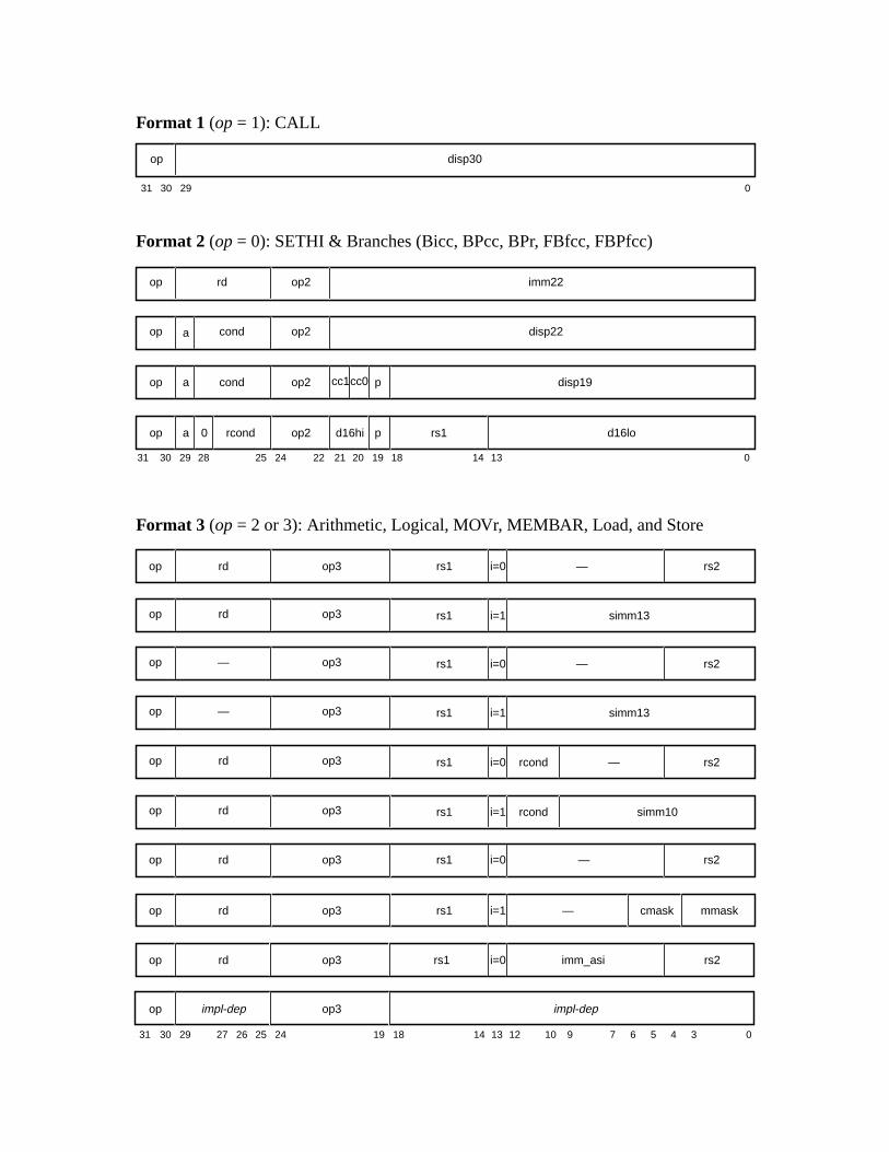
op3rdop rs1 i=1 mmask
31 030 29
disp30op
Format 1 (op= 1): CALL
Format 2 (op= 0): SETHI & Branches (Bicc, BPcc, BPr, FBfcc, FBPfcc)
Format 3 (op= 2 or 3): Arithmetic, Logical, MOVr, MEMBAR, Load, and Store
31 141924 18 13 12 5 4 02530 29
31 2224 21 02530 29
disp22op2condop a
op3rdop —rs1 i=0 rs2
op3rdop rs1 i=1 simm13
disp19op2condop a
d16loop2rcondop a
20 19 1828
0
cc1cc0 p
pd16hi
14 13
rs1
op3rdop rcondrs1 i=0 rs2
op3rdop rs1 i=1 simm10
10 9
rcond
—
—
op3rdop rs1 i=0 rs2—
op3—op —rs1 i=0 rs2
op3—op rs1 i=1 simm13
2627
imm22op2rdop
67
cmask
3
op rd op3 rs1 i=0 imm_asi rs2
op3impl-depop impl-dep

Figure 33—Summary of Instruction Formats: Formats 1, 2, and 3


op3rdop rs1 i=0 rs2
op3rdop rs1 i=1 sw_trap#
cc1cc0 —
cc1cc0
Format 4 (op = 2): MOVcc, FMOVr, FMOVcc, and Tcc
op3rdop rs1 i=1 simm11
31 141924 18 13 12 5 4 02530 29 11 10 9
cc1cc0
7 6
—
op rd op3 cond opf_cc opf_low rs2
op rd op3 0 rcond opf_low rs2rs1
0
17
Format 3 (op = 2 or 3):Continued
31 24 02530 29 19 18
rdop op3 —
14 13 12 5 4
rs1 rs2i=0 x
rdop op3 —rs1 shcnt32i=1 x=0
rdop op3 —rs1 shcnt64i=1 x=1
6
op fcn op3 —
11
op3rdop rs1 —
rdop op3 —cond rs2i=0
rdop op3 cond simm11i=1
cc2
cc2
cc1
cc1
cc0
cc0
op3rdop —
op3rdop rs2opf—
op3rdop rs1 rs2opf
op op3 rs2000 rs1 opfcc1 cc0
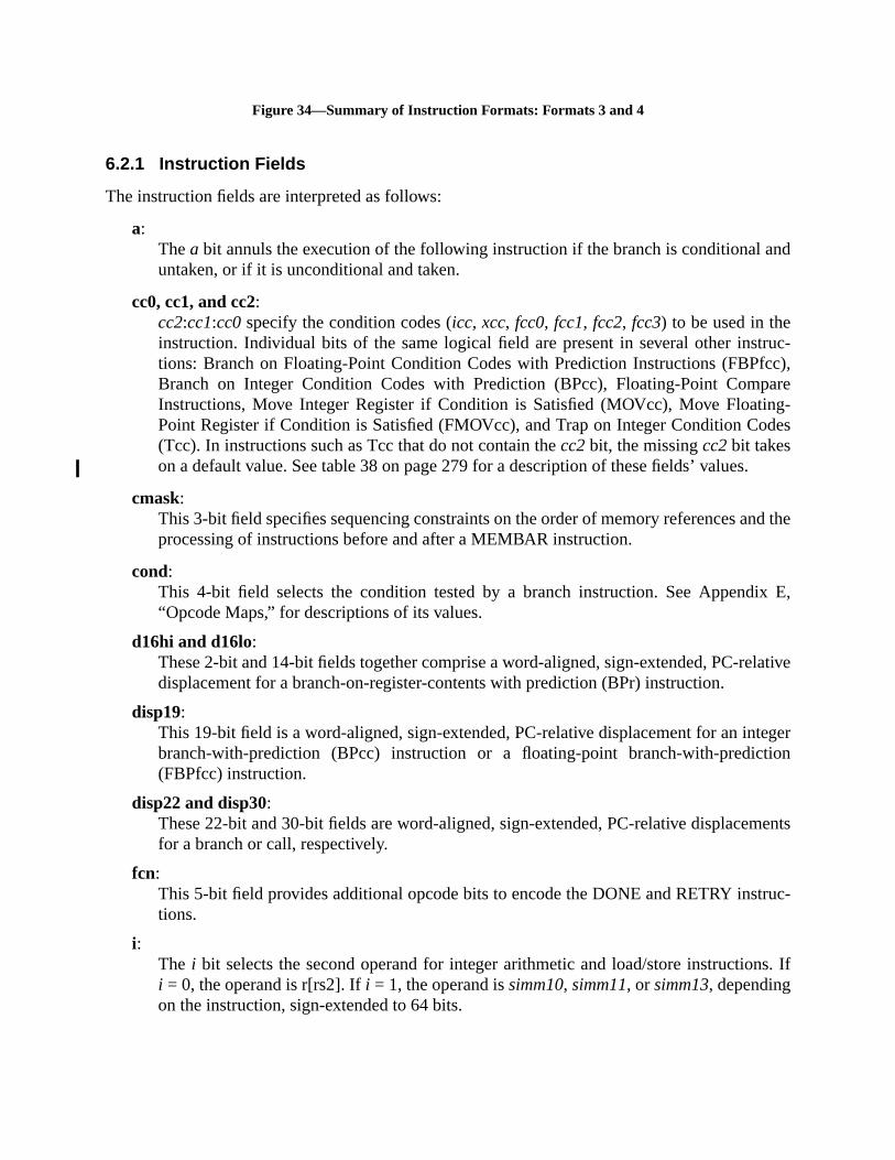
nd
truc-cc),areg-des
.
nd the
ix E,
lative
tegerion
ents
ruc-
ns. If
Figure 34—Summary of Instruction Formats: Formats 3 and 4
6.2.1 Instruction Fields
The instruction fields are interpreted as follows:
a:Thea bit annuls the execution of the following instruction if the branch is conditional auntaken, or if it is unconditional and taken.
cc0, cc1, and cc2:cc2:cc1:cc0specify the condition codes (icc, xcc, fcc0, fcc1, fcc2, fcc3) to be used in theinstruction. Individual bits of the same logical field are present in several other instions: Branch on Floating-Point Condition Codes with Prediction Instructions (FBPfBranch on Integer Condition Codes with Prediction (BPcc), Floating-Point CompInstructions, Move Integer Register if Condition is Satisfied (MOVcc), Move FloatinPoint Register if Condition is Satisfied (FMOVcc), and Trap on Integer Condition Co(Tcc). In instructions such as Tcc that do not contain thecc2bit, the missingcc2bit takeson a default value. See table 38 on page 279 for a description of these fields’ values
cmask:This 3-bit field specifies sequencing constraints on the order of memory references aprocessing of instructions before and after a MEMBAR instruction.
cond:This 4-bit field selects the condition tested by a branch instruction. See Append“Opcode Maps,” for descriptions of its values.
d16hi and d16lo:These 2-bit and 14-bit fields together comprise a word-aligned, sign-extended, PC-redisplacement for a branch-on-register-contents with prediction (BPr) instruction.
disp19:This 19-bit field is a word-aligned, sign-extended, PC-relative displacement for an inbranch-with-prediction (BPcc) instruction or a floating-point branch-with-predict(FBPfcc) instruction.
disp22 and disp30:These 22-bit and 30-bit fields are word-aligned, sign-extended, PC-relative displacemfor a branch or call, respectively.
fcn:This 5-bit field provides additional opcode bits to encode the DONE and RETRY insttions.
i:The i bit selects the second operand for integer arithmetic and load/store instructioi = 0, the operand is r[rs2]. Ifi = 1, the operand issimm10, simm11, or simm13, dependingon the instruction, sign-extended to 64 bits.
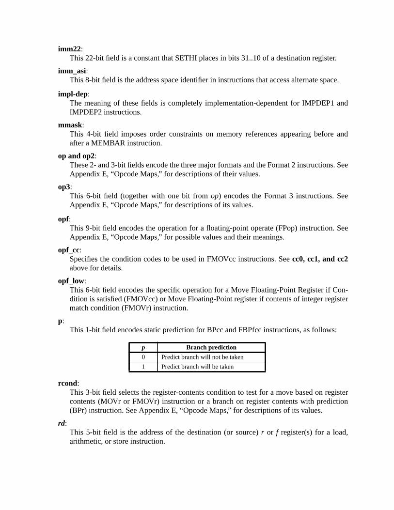
r.
ace.
and
e and
s. See
e
. See
on-ster
s:
gistertion
imm22:This 22-bit field is a constant that SETHI places in bits 31..10 of a destination registe
imm_asi:This 8-bit field is the address space identifier in instructions that access alternate sp
impl-dep:The meaning of these fields is completely implementation-dependent for IMPDEP1IMPDEP2 instructions.
mmask:This 4-bit field imposes order constraints on memory references appearing beforafter a MEMBAR instruction.
op and op2:These 2- and 3-bit fields encode the three major formats and the Format 2 instructionAppendix E, “Opcode Maps,” for descriptions of their values.
op3:This 6-bit field (together with one bit fromop) encodes the Format 3 instructions. SeAppendix E, “Opcode Maps,” for descriptions of its values.
opf:This 9-bit field encodes the operation for a floating-point operate (FPop) instructionAppendix E, “Opcode Maps,” for possible values and their meanings.
opf_cc:Specifies the condition codes to be used in FMOVcc instructions. Seecc0, cc1, and cc2above for details.
opf_low:This 6-bit field encodes the specific operation for a Move Floating-Point Register if Cdition is satisfied (FMOVcc) or Move Floating-Point register if contents of integer regimatch condition (FMOVr) instruction.
p:This 1-bit field encodes static prediction for BPcc and FBPfcc instructions, as follow
rcond:This 3-bit field selects the register-contents condition to test for a move based on recontents (MOVr or FMOVr) instruction or a branch on register contents with predic(BPr) instruction. See Appendix E, “Opcode Maps,” for descriptions of its values.
rd:This 5-bit field is the address of the destination (or source)r or f register(s) for a load,arithmetic, or store instruction.
p Branch prediction
0 Predict branch will not be taken
1 Predict branch will be taken
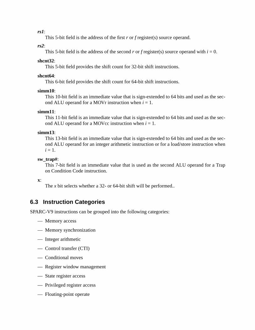
e sec-
e sec-
e sec-hen
Trap
rs1:This 5-bit field is the address of the firstr or f register(s) source operand.
rs2:This 5-bit field is the address of the secondr or f register(s) source operand withi = 0.
shcnt32:This 5-bit field provides the shift count for 32-bit shift instructions.
shcnt64:This 6-bit field provides the shift count for 64-bit shift instructions.
simm10:This 10-bit field is an immediate value that is sign-extended to 64 bits and used as thond ALU operand for a MOVr instruction wheni = 1.
simm11:This 11-bit field is an immediate value that is sign-extended to 64 bits and used as thond ALU operand for a MOVcc instruction wheni = 1.
simm13:This 13-bit field is an immediate value that is sign-extended to 64 bits and used as thond ALU operand for an integer arithmetic instruction or for a load/store instruction wi = 1.
sw_trap#:This 7-bit field is an immediate value that is used as the second ALU operand for aon Condition Code instruction.
x:Thex bit selects whether a 32- or 64-bit shift will be performed..
6.3 Instruction Categories
SPARC-V9 instructions can be grouped into the following categories:
— Memory access
— Memory synchronization
— Integer arithmetic
— Control transfer (CTI)
— Conditional moves
— Register window management
— State register access
— Privileged register access
— Floating-point operate
e onlyer twond
, the
regis-Forory
al, theoca-
.
dou-word,nd CAS
n be
uc-es shallndaries,
s a
ble-
— Implementation-dependent
— Reserved
Each of these categories is further described in the following subsections.
6.3.1 Memory Access Instructions
Load, Store, Prefetch, Load Store Unsigned Byte, Swap, and Compare and Swap are thinstructions that access memory. All of the instructions except Compare and Swap use eithr registers or anr register andsimm13to calculate a 64-bit byte memory address. Compare aSwap uses a singler register to specify a 64-bit byte memory address. To this 64-bit addressIU appends an ASI that encodes address space information.
The destination field of a memory reference instruction specifies ther or f register(s) that supplythe data for a store or receive the data from a load or LDSTUB. For SWAP, the destinationter identifies ther register to be exchanged atomically with the calculated memory location.Compare and Swap, anr register is specified whose value is compared with the value in memat the computed address. If the values are equal, the destination field specifies ther register that isto be exchanged atomically with the addressed memory location. If the values are unequdestination field specifies ther register that is to receive the value at the addressed memory ltion; in this case, the addressed memory location remains unchanged.
The destination field of a PREFETCH instruction is used to encode the type of the prefetch
Integer load and store instructions support byte (8-bit), halfword (16-bit), word (32-bit), andbleword (64-bit) accesses. Floating-point load and store instructions support word, doubleand quadword memory accesses. LDSTUB accesses bytes, SWAP accesses words, aaccesses words or doublewords. PREFETCH accesses at least 64 bytes.
Programming Note:By setting i = 1 andrs1= 0, any location in the lowest or highest 4K bytes of an address space caaccessed without using a register to hold part of the address.
6.3.1.1 Memory Alignment Restrictions
Halfword accesses shall bealigned on 2-byte boundaries, word accesses (which include instrtion fetches) shall be aligned on 4-byte boundaries, extended word and doubleword accessbe aligned on 8-byte boundaries, and quadword accesses shall be aligned on 16-byte bouwith the following exceptions.
An improperly aligned address in a load, store, or load-store instruction causemem_address_not_aligned exception to occur, except:
— An LDDF or LDDFA instruction accessing an address that is word-aligned but not douword-aligned may cause anLDDF_mem_address_not_aligned exception, or may completethe operation in hardware (impl. dep. #109).

uble-
uad-
uad-
datao pos-Regis-
yte’sare illus-
ndian
t bytet byte
(bitst byte
s ared in the
dians to the
— An STDF or STDFA instruction accessing an address that is word-aligned but not doword-aligned may cause anSTDF_mem_address_not_aligned exception or may completethe operation in hardware (impl. dep. #110).
— An LDQF or LDQFA instruction accessing an address that is word-aligned but not qword-aligned may cause anLDQF_mem_address_not_aligned exception or may completethe operation in hardware (impl. dep. #111).
— An STQF or STQFA instruction accessing an address that is word-aligned but not qword aligned may cause anSTQF_mem_address_not_aligned exception or may completethe operation in hardware (impl. dep. #112).
6.3.1.2 Addressing Conventions
SPARC-V9 uses big-endian byte order for all instruction accesses and, by default, foraccesses. It is possible to access data in little-endian format by using selected ASIs. It is alssible to change the default byte order for implicit data accesses. See 5.2.1, “Processor Stateter (PSTATE),” for more information.1
6.3.1.2.1 Big-Endian Addressing Convention
Within a multiple-byte integer, the byte with the smallest address is the most significant; a bsignificance decreases as its address increases. The big-endian addressing conventionstrated in figure 35 and defined as follows:
byte:A load/store byte instruction accesses the addressed byte in both big- and little-emodes.
halfword :For a load/store halfword instruction, two bytes are accessed. The most significan(bits 15..8) is accessed at the address specified in the instruction; the least significan(bits 7..0) is accessed at the address + 1.
word:For a load/store word instruction, four bytes are accessed. The most significant byte31..24) is accessed at the address specified in the instruction; the least significan(bits 7..0) is accessed at the address + 3.
doubleword or extended word:For a load/store extended or floating-point load/store double instruction, eight byteaccessed. The most significant byte (bits 63..56) is accessed at the address specifieinstruction; the least significant byte (bits 7..0) is accessed at the address + 7.For the deprecated integer load/store double instructions (LDD/STD), two big-enwords are accessed. The word at the address specified in the instruction correspond
1.See Cohen, D., “On Holy Wars and a Plea for Peace,”Computer 14:10 (October 1981), pp. 48-54.

e fol-
ificantignifi-
yte’sre illus-
ndian
even register specified in the instruction; the word at address + 4 corresponds to thlowing odd-numbered register.
quadword:For a load/store quadword instruction, sixteen bytes are accessed. The most signbyte (bits 127..120) is accessed at the address specified in the instruction; the least scant byte (bits 7..0) is accessed at the address + 15.
Figure 35—Big-Endian Addressing Conventions
6.3.1.2.2 Little-Endian Addressing Convention
Within a multiple-byte integer, the byte with the smallest address is the least significant; a bsignificance increases as its address increases. The little-endian addressing conventions atrated in figure 36 and defined as follows:
byte:A load/store byte instruction accesses the addressed byte in both big- and little-emodes.
Byte7 0
Halfword15 0
Word31 0
Doubleword /63 32
31 0
78
15 78162324
47 3940485556
15 78162324
0 1
00 01 10 11
Address
Address<0> =
Address<1:0> =
Address<2:0> =
Address<2:0> =
000 001 010 011
100 101 110 111
Quadword127 96
95 64
111 103104112119120
79 7172808788
Address<3:0> =
Address<3:0> =
0000 0001 0010 0011
0100 0101 0110 0111
63 32
31 0
47 3940485556
15 78162324
Address<3:0> =
Address<3:0> =
1000 1001 1010 1011
1100 1101 1110 1111
Extended word

t bytet byte
(bitse (bits
s arein the
diannds to
n the
halfword :For a load/store halfword instruction, two bytes are accessed. The least significan(bits 7..0) is accessed at the address specified in the instruction; the most significan(bits 15..8) is accessed at the address + 1.
word:For a load/store word instruction, four bytes are accessed. The least significant byte7..0) is accessed at the address specified in the instruction; the most significant byt31..24) is accessed at the address + 3.
doubleword or extended word:For a load/store extended or floating-point load/store double instruction, eight byteaccessed. The least significant byte (bits 7..0) is accessed at the address specifiedinstruction; the most significant byte (bits 63..56) is accessed at the address + 7.For the deprecated integer load/store double instructions (LDD/STD), two little-enwords are accessed. The word at the address specified in the instruction + 4 correspothe even register specified in the instruction; the word at the address specified iinstruction corresponds to the following odd-numbered register.
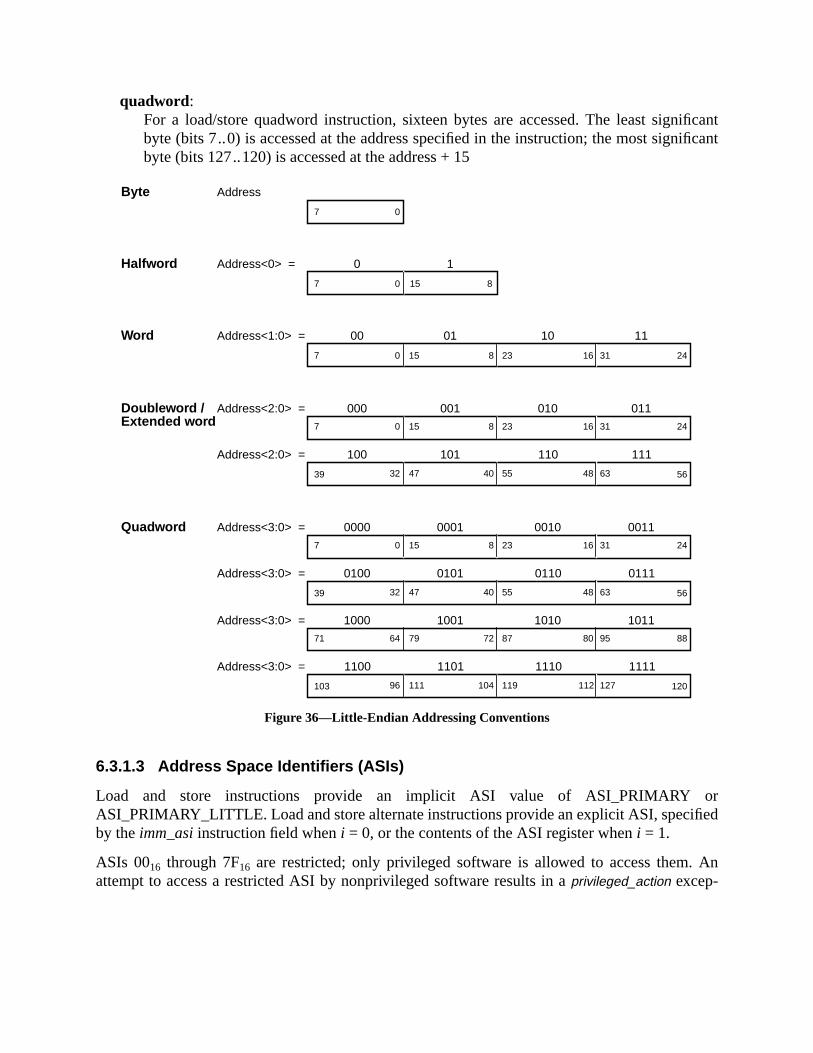
ificantificant
orfied
An
quadword:For a load/store quadword instruction, sixteen bytes are accessed. The least signbyte (bits 7..0) is accessed at the address specified in the instruction; the most signbyte (bits 127..120) is accessed at the address + 15
Figure 36—Little-Endian Addressing Conventions
6.3.1.3 Address Space Identifiers (ASIs)
Load and store instructions provide an implicit ASI value of ASI_PRIMARYASI_PRIMARY_LITTLE. Load and store alternate instructions provide an explicit ASI, speciby theimm_asi instruction field wheni = 0, or the contents of the ASI register wheni = 1.
ASIs 0016 through 7F16 are restricted; only privileged software is allowed to access them.attempt to access a restricted ASI by nonprivileged software results in aprivileged_action excep-
Byte7 0
Halfword7 8
Word7 24
Doubleword /
150
23 31168150
0 1
00 01 10 11
Address
Address<0> =
Address<1:0> =
Address<2:0> =
Address<2:0> =
000 001 010 011
100 101 110 111
Quadword Address<3:0> =
Address<3:0> =
0000 0001 0010 0011
0100 0101 0110 0111
Address<3:0> =
Address<3:0> =
1000 1001 1010 1011
1100 1101 1110 1111
39 5655 6348404732
7 2423 31168150
39 5655 6348404732
7 2423 31168150
103 120119 12711210411196
71 8887 9580727964
Extended word

pro-
ASI,
tion. ASIs 8016 through FF16 are unrestricted; software is allowed to access them whether thecessor is operating in privileged or nonprivileged mode. This is illustrated in table 11.
The required ASI assignments are shown in table 12. In the table, “R” indicates a restrictedand “U” indicates an unrestricted ASI.
IMPL. DEP. #29: These ASI assignments are implementation-dependent: restricted ASIs 0016..0316,0516..0B16, 0D16..0F16, 1216..1716, AND 1A16..7F16; and unrestricted ASIs C016 .. FF16.
IMPL. DEP. #30: An implementation may choose to decode only a subset of the 8-bit ASI specifier; how-ever, it shall decode at least enough of the ASI to distinguish ASI_PRIMARY, ASI_PRIMARY_LITTLE,ASI_AS_IF_USER_PRIMARY, ASI_AS_IF_USER_PRIMARY_LITTLE, ASI_PRIMARY_NOFAULT,ASI_PRIMARY_NOFAULT_LITTLE, ASI_SECONDARY, ASI_SECONDARY_LITTLE,ASI_AS_IF_USER_SECONDARY, ASI_AS_IF_USER_SECONDARY_LITTLE,ASI_SECONDARY_NOFAULT, and ASI_SECONDARY_NOFAULT_LITTLE. If the nucleus context is sup-ported, then ASI_NUCLEUS and ASI_NUCLEUS_LITTLE must also be decoded (impl. dep. #124).Finally, an implementation must always decode ASI bit<7> while PSTATE.PRIV = 0, so that an attempt bynonprivileged software to access a restricted ASI will always cause a privileged_action exception.
Table 11—Allowed Accesses to ASIs
Value Access Type Processor state(PSTATE.PRIV) Result of ASI access
0016..7F16 RestrictedNonprivileged (0) privileged_action exception
Privileged (1) Valid access
8016..FF16 UnrestrictedNonprivileged (0) Valid access
Privileged (1) Valid access
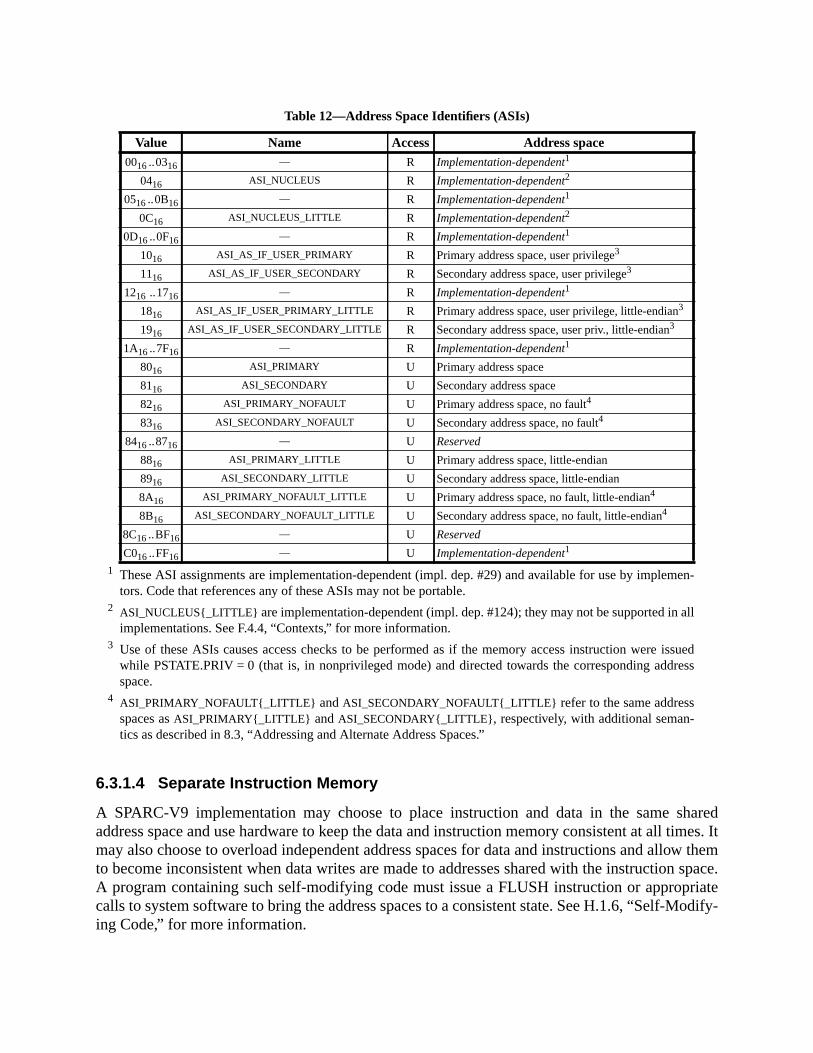
n-
l
ueds
haredtimes. Itw themspace.
riateodify-
1 These ASI assignments are implementation-dependent (impl. dep. #29) and available for use by implemetors. Code that references any of these ASIs may not be portable.
2 ASI_NUCLEUS{_LITTLE} are implementation-dependent (impl. dep. #124); they may not be supported in alimplementations. See F.4.4, “Contexts,” for more information.
3 Use of these ASIs causes access checks to be performed as if the memory access instruction were isswhile PSTATE.PRIV = 0 (that is, in nonprivileged mode) and directed towards the corresponding addresspace.
4 ASI_PRIMARY_NOFAULT{_LITTLE} andASI_SECONDARY_NOFAULT{_LITTLE} refer to the same addressspaces asASI_PRIMARY{_LITTLE} andASI_SECONDARY{_LITTLE}, respectively, with additional seman-tics as described in 8.3, “Addressing and Alternate Address Spaces.”
6.3.1.4 Separate Instruction Memory
A SPARC-V9 implementation may choose to place instruction and data in the same saddress space and use hardware to keep the data and instruction memory consistent at allmay also choose to overload independent address spaces for data and instructions and alloto become inconsistent when data writes are made to addresses shared with the instructionA program containing such self-modifying code must issue a FLUSH instruction or appropcalls to system software to bring the address spaces to a consistent state. See H.1.6, “Self-Ming Code,” for more information.
Table 12—Address Space Identifiers (ASIs)
Value Name Access Address space0016..0316 — R Implementation-dependent1
0416 ASI_NUCLEUS R Implementation-dependent2
0516..0B16 — R Implementation-dependent1
0C16 ASI_NUCLEUS_LITTLE R Implementation-dependent2
0D16..0F16 — R Implementation-dependent1
1016 ASI_AS_IF_USER_PRIMARY R Primary address space, user privilege3
1116 ASI_AS_IF_USER_SECONDARY R Secondary address space, user privilege3
1216 ..1716 — R Implementation-dependent1
1816 ASI_AS_IF_USER_PRIMARY_LITTLE R Primary address space, user privilege, little-endian3
1916 ASI_AS_IF_USER_SECONDARY_LITTLE R Secondary address space, user priv., little-endian3
1A16..7F16 — R Implementation-dependent1
8016 ASI_PRIMARY U Primary address space
8116 ASI_SECONDARY U Secondary address space
8216 ASI_PRIMARY_NOFAULT U Primary address space, no fault4
8316 ASI_SECONDARY_NOFAULT U Secondary address space, no fault4
8416..8716 — U Reserved
8816 ASI_PRIMARY_LITTLE U Primary address space, little-endian
8916 ASI_SECONDARY_LITTLE U Secondary address space, little-endian
8A16 ASI_PRIMARY_NOFAULT_LITTLE U Primary address space, no fault, little-endian4
8B16 ASI_SECONDARY_NOFAULT_LITTLE U Secondary address space, no fault, little-endian4
8C16..BF16 — U Reserved
C016..FF16 — U Implementation-dependent1
andets ofl oversub-
n to
mputestina-
s (rison
ct and
hift
tr 10struct
,
6.3.2 Memory Synchronization Instructions
Two forms of memory barrier (MEMBAR) instructions allow programs to manage the ordercompletion of memory references. Ordering MEMBARs induce a partial ordering between sloads and stores and future loads and stores. Sequencing MEMBARs exert explicit controcompletion of loads and stores. Both barrier forms are encoded in a single instruction, withfunctions bit-encoded in an immediate field.
Compatibility Note:The deprecated STBAR instruction is a subcase of the MEMBAR instruction; it is identical in operatiothe STBAR instruction of SPARC-V8, and is included only for compatibility.
6.3.3 Integer Arithmetic Instructions
The integer arithmetic instructions are generally triadic-register-address instructions that coa result which is a function of two source operands. They either write the result into the detion registerr[rd] or discard it. One of the source operands is always r[rs1]. The other sourceoperand depends on thei bit in the instruction; ifi = 0, the operand isr[rs2]; if i = 1, the operandis the constantsimm10, simm11, orsimm13 sign-extended to 64 bits.
Note that the value ofr[0] always reads as zero, and writes to it are ignored.
6.3.3.1 Setting Condition Codes
Most integer arithmetic instructions have two versions; one sets the integer condition codeiccand xcc) as a side effect; the other does not affect the condition codes. A special compainstruction for integer values is not needed, since it is easily synthesized using the “subtraset condition codes” (SUBcc) instruction. See G.3, “Synthetic Instructions,” for details.
6.3.3.2 Shift Instructions
Shift instructions shift anr register left or right by a constant or variable amount. None of the sinstructions changes the condition codes.
6.3.3.3 Set High 22 Bits of Low Word
The “set high 22 bits of low word of anr register” instruction (SETHI) writes a 22-bit constanfrom the instruction into bits 31 through 10 of the destination register. It clears the low-ordebits and high-order 32 bits, and does not affect the condition codes. Its primary use is to conconstants in registers.
6.3.3.4 Integer Multiply/Divide
The integer multiply instruction performs a 64× 64 → 64-bit operation; the integer divideinstructions perform 64÷ 64 → 64-bit operations. For compatibility with SPARC-V8

o low-metic
-
Bc-
nPC)nPC).rol is. The
nnul,takenthey
fter abit canloop.n “if-condi-that an
grams that
32 × 32 → 64-bit multiply instructions, 64÷ 32 → 32-bit divide instructions, and the multiplystep instruction are provided. Division by zero causes adivision_by_zero exception.
6.3.3.5 Tagged Add/Subtract
The tagged add/subtract instructions assume tagged-format data, in which the tag is the tworder bits of each operand. If either of the two operands has a nonzero tag, or if 32-bit arithoverflow occurs, tag overflow is detected. TADDcc and TSUBcc set the CCR.icc.V bit if tag over-flow occurs; they set the CCR.xcc.V bit if 64-bit arithmetic overflow occurs. The trapping versions (TADDccTV, TSUBccTV) of these instructions cause atag_overflow trap if tag overflowoccurs. If 64-bit arithmetic overflow occurs but tag overflow does not, TADDccTV and TSUcTV set the CCR.xcc.V bit but do not trap.
6.3.4 Control-Transfer Instructions (CTIs)
These are the basic control-transfer instruction types:
— Conditional branch (Bicc, BPcc, BPr, FBfcc, FBPfcc)
— Unconditional Branch
— Call and Link (CALL)
— Jump and Link (JMPL, RETURN)
— Return from trap (DONE, RETRY)
— Trap (Tcc)
A control-transfer instruction functions by changing the value of the next program counter (or by changing the value of both the program counter (PC) and the next program counter (When only the next program counter, nPC, is changed, the effect of the transfer of contdelayed by one instruction. Most control transfers in SPARC-V9 are of the delayed varietyinstruction following a delayed control transfer instruction is said to be in thedelay slot of thecontrol transfer instruction. Some control transfer instructions (branches) can optionally athat is, not execute, the instruction in the delay slot, depending upon whether the transfer isor not-taken. Annulled instructions have no effect upon the program-visible state nor cancause a trap.
Programming Note:The annul bit increases the likelihood that a compiler can find a useful instruction to fill the delay slot abranch, thereby reducing the number of instructions executed by a program. For example, the annulbe used to move an instruction from within a loop to fill the delay slot of the branch that closes theLikewise, the annul bit can be used to move an instruction from either the “else” or “then” branch of athen-else” program block to the delay slot of the branch that selects between them. Since a full set oftions are provided, a compiler can arrange the code (possibly reversing the sense of the condition) soinstruction from either the “else” branch or the “then” branch can be moved to the delay slot.
Table 13 below defines the value of the program counter and the value of the next procounter after execution of each instruction. Conditional branches have two forms: branche
hat is,howntruc-
. The
diateace-
ignifi-fis
bys of
L] or
nulledif it is
controls com-
test a condition, represented in the table by “Bcc,” and branches that are unconditional, talways or never taken, represented in the table by “B.” The effect of an annulled branch is sin the table through explicit transfers of control, rather than by fetching and annulling the instion.
The effective address, EA in table 13, specifies the target of the control transfer instructioneffective address is computed in different ways, depending on the particular instruction:
PC-relative Effective Address:A PC-relative effective address is computed by sign extending the instruction’s immefield to 64-bits, left-shifting the word displacement by two bits to create a byte displment, and adding the result to the contents of the PC.
Register-Indirect Effective Address:A register-indirect effective address computes its target address as either r[rs1]+r [rs2] if i= 0, or r[rs1]+sign_ext(simm13) if i = 1 .
Trap Vector Effective Address:A trap vector effective address first computes the software trap number as the least scant seven bits ofr[rs1]+r [rs2] if i = 0 , or as the least significant seven bits or[rs1]+sw_trap# if i = 1 . The trap level, TL, is incremented. The hardware trap typecomputed as 256 +sw_trap#and stored in TT[TL]. The effective address is generatedconcatenating the contents of the TBA register, the “TL>0” bit, and the contentTT[TL]. See 5.2.8, “Trap Base Address (TBA),” for details.
Trap State Effective Address:A trap state effective address is not computed, but is taken directly from either TPC[TTNPC[TL].
Compatibility Note:SPARC-V8 specified that the delay instruction was always fetched, even if annulled, and that an aninstruction could not cause any traps. SPARC-V9 does not require the delay instruction to be fetchedannulled.
Compatibility Note:SPARC-V8 left as undefined the result of executing a delayed conditional branch that had a delayedtransfer in its delay slot. For this reason, programmers should avoid such constructs when backwardpatibility is an issue.
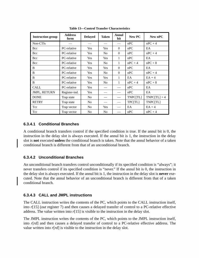
theelayken
”; itn in
aken
elf,ctive
self,. The
6.3.4.1 Conditional Branches
A conditional branch transfers control if the specified condition is true. If the annul bit is 0,instruction in the delay slot is always executed. If the annul bit is 1, the instruction in the dslot isnot executedunlessthe conditional branch is taken. Note that the annul behavior of a taconditional branch is different from that of an unconditional branch.
6.3.4.2 Unconditional Branches
An unconditional branch transfers control unconditionally if its specified condition is “alwaysnever transfers control if its specified condition is “never.” If the annul bit is 0, the instructiothe delay slot is always executed. If the annul bit is 1, the instruction in the delay slot isneverexe-cuted. Note that the annul behavior of an unconditional branch is different from that of a tconditional branch.
6.3.4.3 CALL and JMPL instructions
The CALL instruction writes the contents of the PC, which points to the CALL instruction itsinto r[15] (out register 7) and then causes a delayed transfer of control to a PC-relative effeaddress. The value written intor[15] is visible to the instruction in the delay slot.
The JMPL instruction writes the contents of the PC, which points to the JMPL instruction itinto r[rd] and then causes a delayed transfer of control to a PC-relative effective addressvalue written intor[rd] is visible to the instruction in the delay slot.
Table 13—Control Transfer Characteristics
Instruction group Addressform Delayed Taken Annul
bit New PC New nPC
Non-CTIs — — — — nPC nPC + 4
Bcc PC-relative Yes Yes 0 nPC EA
Bcc PC-relative Yes No 0 nPC nPC + 4
Bcc PC-relative Yes Yes 1 nPC EA
Bcc PC-relative Yes No 1 nPC + 4 nPC + 8
B PC-relative Yes Yes 0 nPC EA
B PC-relative Yes No 0 nPC nPC + 4
B PC-relative Yes Yes 1 EA EA + 4
B PC-relative Yes No 1 nPC + 4 nPC + 8
CALL PC-relative Yes — — nPC EA
JMPL, RETURN Register-ind. Yes — — nPC EA
DONE Trap state No — — TNPC[TL] TNPC[TL] + 4
RETRY Trap state No — — TPC[TL] TNPC[TL]
Tcc Trap vector No Yes — EA EA + 4
Tcc Trap vector No No — nPC nPC + 4

.
ode.
hese
to thep, thattever
eandBase
s theonlytrap is
e used
isterst iscon-
When PSTATE.AM = 1, the value of the high order 32-bits transmitted tor[15] by the CALLinstruction or tor[rd] by the JMPL instruction is implementation-dependent. (impl. dep #125)
6.3.4.4 RETURN Instruction
The RETURN instruction is used to return from a trap handler executing in nonpriviliged mRETURN combines the control-transfer characteristics of a JMPL instruction withr[0] specifiedas the destination register and the register-window semantics of a RESTORE instruction.
6.3.4.5 DONE and RETRY Instructions
The DONE and RETRY instructions are used by privileged software to return from a trap. Tinstructions restore the machine state to values saved in the TSTATE register.
RETRY returns to the instruction that caused the trap in order to reexecute it. DONE returnsinstruction pointed to by the value of nPC associated with the instruction that caused the trais, the next logical instruction in the program. DONE presumes that the trap handler did whawas requested by the program and that execution should continue.
6.3.4.6 Trap Instruction (Tcc)
The Tcc instruction initiates a trap if the condition specified by itscondfield matches the currentstate of the condition code register specified by itscc field, otherwise it executes as a NOP. If thtrap is taken, it increments the TL register, computes a trap type which is stored in TT[TL],transfers to a computed address in the trap table pointed to by TBA. See 5.2.8, “TrapAddress (TBA).”
A Tcc instruction can specify one of 128 software trap types. When a Tcc is taken, 256 pluseven least significant bits of the sum of the Tcc’s source operands is written to TT[TL]. Thevisible difference between a software trap generated by a Tcc instruction and a hardwarethe trap number in the TT register. See Chapter 7, “Traps,” for more information.
Programming Note:Tcc can be used to implement breakpointing, tracing, and calls to supervisor software. Tcc can also bfor run-time checks, such as out-of-range array index checks or integer overflow checks.
6.3.5 Conditional Move Instructions
6.3.5.1 MOVcc and FMOVcc Instructions
The MOVcc and FMOVcc instructions copy the contents of any integer or floating-point regto a destination integer or floating-point register if a condition is satisfied. The condition to tespecified in the instruction and may be any of the conditions allowed in conditional delayedtrol-transfer instructions. This condition is tested against one of the six condition codes (icc, xcc,fcc0, fcc1, fcc2, andfcc3) as specified by the instruction. For example:
fmovdg %fcc2, %f20, %f22
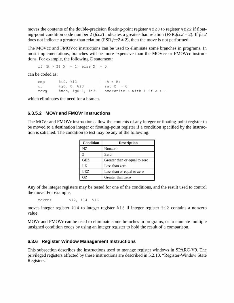
s. Intruc-
r totruc-
ontrol
ltiple
9. TheState
moves the contents of the double-precision floating-point register%f20 to register%f22 if float-ing-point condition code number 2 (fcc2) indicates a greater-than relation (FSR.fcc2= 2). If fcc2does not indicate a greater-than relation (FSR.fcc2≠ 2), then the move is not performed.
The MOVcc and FMOVcc instructions can be used to eliminate some branches in programmost implementations, branches will be more expensive than the MOVcc or FMOVcc instions. For example, the following C statement:
if (A > B) X = 1; else X = 0;
can be coded as:
cmp %i0, %i2 ! (A > B)or %g0, 0, %i3 ! set X = 0movg %xcc, %g0,1, %i3 ! overwrite X with 1 if A > B
which eliminates the need for a branch.
6.3.5.2 MOVr and FMOVr Instructions
The MOVr and FMOVr instructions allow the contents of any integer or floating-point registebe moved to a destination integer or floating-point register if a condition specified by the instion is satisfied. The condition to test may be any of the following:
Any of the integer registers may be tested for one of the conditions, and the result used to cthe move. For example,
movrnz %i2, %l4, %l6
moves integer register%l4 to integer register%l6 if integer register%i2 contains a nonzerovalue.
MOVr and FMOVr can be used to eliminate some branches in programs, or to emulate muunsigned condition codes by using an integer register to hold the result of a comparison.
6.3.6 Register Window Management Instructions
This subsection describes the instructions used to manage register windows in SPARC-Vprivileged registers affected by these instructions are described in 5.2.10, “Register-WindowRegisters.”
Condition Description
NZ Nonzero
Z Zero
GEZ Greater than or equal to zero
LZ Less than zero
LEZ Less than or equal to zero
GZ Greater than zero
w by
, andone
win-
regis-
NRE-in-
to a
and
isterossi-,
ion. Aess foro the
r in anWin-
l has
6.3.6.1 SAVE Instruction
The SAVE instruction allocates a new register window and saves the caller’s register windoincrementing the CWP register.
If CANSAVE = 0, execution of a SAVE instruction causes awindow_spill exception.
If CANSAVE ≠ 0, but the number of clean windows is zero, that is:
(CLEANWIN – CANRESTORE) = 0
then SAVE causes aclean_window exception.
If SAVE does not cause an exception, it performs an ADD operation, decrements CANSAVEincrements CANRESTORE. The source registers for the ADD are from the old window (theto which CWP pointed before the SAVE), while the result is written into a register in the newdow (the one to which the incremented CWP points).
6.3.6.2 RESTORE Instruction
The RESTORE instruction restores the previous register window by decrementing the CWPter.
If CANRESTORE = 0, execution of a RESTORE instruction causes awindow_fill exception.
If RESTORE does not cause an exception, it performs an ADD operation, decrements CASTORE, and increments CANSAVE. The source registers for the ADD are from the “old” wdow (the one to which CWP pointed before the RESTORE), while the result is written inregister in the “new” window (the one to which the decremented CWP points).
Programming Note:The following describes a common convention for use of register windows, SAVE, RESTORE, CALL,JMPL instructions.
A procedure is invoked by executing a CALL (or a JMPL) instruction. If the procedure requires a regwindow, it executes a SAVE instruction. A routine that does not allocate a register window of its own (pbly a leaf procedure) should not modify any windowed registers exceptout registers 0 through 6. See H.1.2“Leaf-Procedure Optimization.”
A procedure that uses a register window returns by executing both a RESTORE and a JMPL instructprocedure that has not allocated a register window returns by executing a JMPL only. The target addrthe JMPL instruction is normally eight plus the address saved by the calling instruction, that is, tinstruction after the instruction in the delay slot of the calling instruction.
The SAVE and RESTORE instructions can be used to atomically establish a new memory stack pointer register and switch to a new or previous register window. See H.1.4, “Register Allocation within adow.”
6.3.6.3 SAVED Instruction
The SAVED instruction should be used by a spill trap handler to indicate that a window spilcompleted successfully. It increments CANSAVE:
AVED
has
pace
), so
N-
per-p ifdows
hasillbeen
CANSAVE ← (CANSAVE + 1)
If the saved window belongs to a different address space (OTHERWIN≠ 0), it decrements OTH-ERWIN:
OTHERWIN ← (OTHERWIN – 1)
Otherwise, the saved window belongs to the current address space (OTHERWIN = 0), so Sdecrements CANRESTORE:
CANRESTORE← (CANRESTORE – 1)
6.3.6.4 RESTORED Instruction
The RESTORED instruction should be used by a fill trap handler to indicate that a windowbeen filled successfully. It increments CANRESTORE:
CANRESTORE← (CANRESTORE+ 1)
If the restored window replaces a window that belongs to a different address s(OTHERWIN ≠ 0), it decrements OTHERWIN:
OTHERWIN ← (OTHERWIN – 1)
Otherwise, the restored window belongs to the current address space (OTHERWIN = 0RESTORED decrements CANSAVE:
CANSAVE ← (CANSAVE – 1)
If CLEANWIN is less than NWINDOWS-1, the RESTORED instruction increments CLEAWIN:
if (CLEANWIN < (NWINDOWS-1))then CLEANWIN ← (CLEANWIN + 1)
6.3.6.5 Flush Windows Instruction
The FLUSHW instruction flushes all of the register windows except the current window, byforming repetitive spill traps. The FLUSHW instruction is implemented by causing a spill traany register window (other than the current window) has valid contents. The number of winwith valid contents is computed as
NWINDOWS – 2 – CANSAVE
If this number is nonzero, the FLUSHW instruction causes a spill trap. Otherwise, FLUSHWno effect. If the spill trap handler exits with a RETRY instruction, the FLUSHW instruction wcontinue causing spill traps until all the register windows except the current window haveflushed.
. These-
le only
tions.in one
d
f
d doesload/
s do
for
tion
n.
n.rate
s
6.3.7 State Register Access
The read/write state register instructions access program-visible state and status registersinstructions read/write the state registers into/fromr registers. A read/write Ancillary State Register instruction is privileged only if the accessed register is privileged.
6.3.8 Privileged Register Access
The read/write privileged register instructions access state and status registers that are visibto privileged software. These instructions read/write privileged registers into/fromr registers. Theread/write privileged register instructions are privileged.
6.3.9 Floating-Point Operate (FPop) Instructions
Floating-point operate instructions (FPops) are generally triadic-register-address instrucThey compute a result that is a function of one or two source operands and place the resultor more destinationf registers. The exceptions are:
— Floating-point convert operations, which use one source and one destination operan
— Floating-point compare operations, which do not write to anf register, but update one othefccn fields of the FSR instead
The term “FPop” refers to those instructions encoded by the FPop1 and FPop2 opcodes annot include branches based on the floating-point condition codes (FBfcc and FBPfcc) or thestore floating-point instructions.
The FMOVcc instructions function for the floating-point registers as the MOVcc instructionfor the integer registers. See 6.3.5.1, “MOVcc and FMOVcc Instructions.”
The FMOVr instructions function for the floating-point registers as the MOVr instructions dothe integer registers. See 6.3.5.2, “MOVr and FMOVr Instructions.”
If there is no floating-point unit present or if PSTATE.PEF = 0 or FPRS.FEF = 0, any instructhat attempts to access an FPU register, including an FPop instruction, generates anfp_disabledexception.
All FPop instructions clear theftt field and set thecexcfield, unless they generate an exceptioFloating-point compare instructions also write one of thefccn fields. All FPop instructions thatcan generate IEEE exceptions set thecexcand aexcfields, unless they generate an exceptioFABS(s,d,q), FMOV(s,d,q), FMOVcc(s,d,q), FMOVr(s,d,q), and FNEG(s,d,q) cannot geneIEEE exceptions, so they clearcexcand leaveaexcunchanged. FMOVcc and FMOVr instructionclear these FSR fields regardless of the value of the conditional predicate.
IMPL. DEP. #3: An implementation may indicate that a floating-point instruction did not produce a correctIEEE STD 754-1985 result by generating a special unfinished_FPop or unimplemented_FPop exception.Privileged-mode software must emulate any functionality not present in the hardware.

and
pecifi-
e anthe
istersy theware
true:
uation.
ustcount
houtd in
via thefig-
ddressin a
6.3.10 Implementation-Dependent Instructions
SPARC-V9 provides two instructions that are entirely implementation-dependent, IMPDEP1IMPDEP2 (impl. dep. #106).
Compatibility Note:The IMPDEPn instructions replace the CPopn instructions in SPARC-V8.
See A.23, “Implementation-Dependent Instructions,” for more information.
6.3.11 Reserved Opcodes and Instruction Fields
An attempt to execute an opcode to which no instruction is assigned shall cause a trap. Scally, attempting to execute a reserved FPop causes anfp_exception_other trap (withFSR.ftt = unimplemented_FPop); attempting to execute any other reserved opcode shall causillegal_instruction trap. See Appendix E, “Opcode Maps,” for a complete enumeration ofreserved opcodes.
6.4 Register Window Management
The state of the register windows is determined by the contents of the set of privileged regdescribed in 5.2.10, “Register-Window State Registers.” Those registers are affected binstructions described in 6.3.6, “Register Window Management Instructions.” Privileged softcan read/write these state registers directly by using RDPR/WRPR instructions.
6.4.1 Register Window State Definition
In order for the state of the register windows to be consistent, the following must always be
CANSAVE + CANRESTORE+ OTHERWIN = NWINDOWS – 2
Figure 3 on page 34 shows how the register windows are partitioned to obtain the above eqIn figure 3, the partitions are as follows:
— The current window and the window that overlaps two other valid windows and so mnot be used (in the figure, windows 0 and 4, respectively) are always present and acfor the 2 subtracted from NWINDOWS in the right-hand side of the equation.
— Windows that do not have valid contents and can be used (via a SAVE instruction) witcausing a spill trap. These windows (windows 1, 2 and 3 in the figure) are counteCANSAVE.
— Windows that have valid contents for the current address space and can be used (RESTORE instruction) without causing a fill trap. These windows (window 7 in theure) are counted in CANRESTORE.
— Windows that have valid contents for an address space other than the current aspace. An attempt to use these windows via a SAVE (RESTORE) instruction results
tion.
ing
state ofspill-dowroying
s, to
w issave
gistered
t ine.
con-indow
ftware
urrenttoredn beed by
spill (fill) trap to a separate set of trap vectors, as discussed in the following subsecThese windows (windows 5 and 6 in the figure) are counted in OTHERWIN.
In addition,
CLEANWIN ≥ CANRESTORE
since CLEANWIN is the sum of CANRESTORE and the number of clean windows followCWP.
In order to use the window-management features of the architecture as described here, thethe register windows must be kept consistent at all times, except in trap handlers for windowing, filling, and cleaning. While handling window traps the state may be inconsistent. Winspill/fill strap handlers should be written such that a nested trap can be taken without deststate.
6.4.2 Register Window Traps
Window traps are used to manage overflow and underflow conditions in the register windowsupport clean windows, and to implement the FLUSHW instruction.
6.4.2.1 Window Spill and Fill Traps
A window overflow occurs when a SAVE instruction is executed and the next register windooccupied (CANSAVE = 0). An overflow causes a spill trap that allows privileged software tothe occupied register window in memory, thereby making it available for use.
A window underflow occurs when a RESTORE instruction is executed and the previous rewindow is not valid (CANRESTORE = 0). An underflow causes a fill trap that allows privilegsoftware to load the registers from memory.
6.4.2.2 Clean-Window Trap
SPARC-V9 provides theclean_window trap so that software can create a secure environmenwhich it is guaranteed that register windows contain only data from the same address spac
A clean register window is one in which all of the registers, including uninitialized registers,tain either zero or data assigned by software executing in the address space to which the wbelongs. A clean window cannot contain register values from another process, that is, sooperating in a different address space.
Supervisor software specifies the number of windows that are clean with respect to the caddress space in the CLEANWIN register. This includes register windows that can be res(the value in the CANRESTORE register) and the register windows following CWP that caused without cleaning. Therefore, the number of clean windows that are available to be usthe SAVE instruction is
CLEANWIN – CANRESTORE

t-
ec-
to ans kept
ows
theide.
bespaceld
ndler,
er-
AN-illed
The SAVE instruction causes aclean_window trap if this value is zero. This allows supervisor sofware to clean a register window before it is accessed by a user.
6.4.2.3 Vectoring of Fill/Spill Traps
In order to make handling of fill and spill traps efficient, SPARC-V9 provides multiple trap vtors for the fill and spill traps. These trap vectors are determined as follows:
— Supervisor software can mark a set of contiguous register windows as belongingaddress space different from the current one. The count of these register windows iin the OTHERWIN register. A separate set of trap vectors (fill_n_other andspill_n_other) isprovided for spill and fill traps for these register windows (as opposed to register windthat belong to the current address space).
— Supervisor software can specify the trap vectors for fill and spill traps by presettingfields in the WSTATE register. This register contains two subfields, each three bits wThe WSTATE.NORMAL field is used to determine one of eight spill (fill) vectors toused when the register window to be spilled (filled) belongs to the current address(OTHERWIN = 0). If the OTHERWIN register is nonzero, the WSTATE.OTHER fieselects one of eightfill_n_other (spill_n_other) trap vectors.
See Chapter 7, “Traps,” for more details on how the trap address is determined.
6.4.2.4 CWP on Window Traps
On a window trap the CWP is set to point to the window that must be accessed by the trap haas follows (note that all arithmetic on CWP is done modulo NWINDOWS):
— If the spill trap occurs due to a SAVE instruction (when CANSAVE = 0), there is an ovlap window between the CWP and the next register window to be spilled
CWP← (CWP+ 2) mod NWINDOWS
If the spill trap occurs due to a FLUSHW instruction, there can be unused windows (CSAVE) in addition to the overlap window, between the CWP and the window to be sp
CWP← (CWP+ CANSAVE + 2) mod NWINDOWS
Implementation Note:All spill traps can use:
CWP← (CWP+ CANSAVE + 2) mod NWINDOWS
since CANSAVE is zero whenever a trap occurs due to a SAVE instruction.
— On a fill trap, the window preceding CWP must be filled
CWP← (CWP – 1)mod NWINDOWS
— On a clean_window trap, the window following CWP must be cleaned. Then
CWP← (CWP+ 1) mod NWINDOWS

dgisterAN-da-
ills.
lls.
it
Spill
ns thef ther. TheOne-gener-
e trap
tion, aticularction, itexcep-equest
cutingpro-
6.4.2.5 Window Trap Handlers
The trap handlers for fill, spill andclean_window traps must handle the trap appropriately anreturn using the RETRY instruction, to reexecute the trapped instruction. The state of the rewindows must be updated by the trap handler, and the relationship among CLEANWIN, CSAVE, CANRESTORE, and OTHERWIN must remain consistent. The following recommentions should be followed:
— A spill trap handler should execute the SAVED instruction for each window that it sp
— A fill trap handler should execute the RESTORED instruction for each window that it fi
— A clean_window trap handler should increment CLEANWIN for each window thatcleans:
CLEANWIN ← (CLEANWIN + 1)
Window trap handlers in SPARC-V9 can be very efficient. See H.2.2, “Example Code forHandler,” for details and sample code.
7 Traps7.1 Overview
A trap is a vectored transfer of control to supervisor software through a trap table that contaifirst eight (thirty-two for fill/spill traps) instructions of each trap handler. The base address otable is established by supervisor software, by writing the Trap Base Address (TBA) registedisplacement within the table is determined by the trap type and the current trap level (TL).half of the table is reserved for hardware traps; one-quarter is reserved for software trapsated by Tcc instructions; the remaining quarter is reserved for future use.
A trap behaves like an unexpected procedure call. It causes the hardware to
(1) Save certain processor state (program counters, CWP, ASI, CCR, PSTATE, and thtype) on a hardware register stack
(2) Enter privileged execution mode with a predefined PSTATE
(3) Begin executing trap handler code in the trap vector
When the trap handler has finished, it uses either a DONE or RETRY instruction to return.
A trap may be caused by a Tcc instruction, an SIR instruction, an instruction-induced excepreset, an asynchronous exception, or an interrupt request not directly related to a parinstruction. The processor must appear to behave as though, before executing each instrudetermines if there are any pending exceptions or interrupt requests. If there are pendingtions or interrupt requests, the processor selects the highest-priority exception or interrupt rand causes a trap.
Thus, an exception is a condition that makes it impossible for the processor to continue exethe current instruction stream without software intervention. A trap is the action taken by the

terrupt,
, duestored.resum-
servedand
XTL,
reby the
cessor when it changes the instruction flow in response to the presence of an exception, inor Tcc instruction.
A catastrophic error exception is due to the detection of a hardware malfunction from whichto the nature of the error, the state of the machine at the time of the exception cannot be reSince the machine state cannot be restored, execution after such an exception may not beable. An example of such an error is an uncorrectable bus parity error.
IMPL. DEP. #31: The causes and effects of catastrophic errors are implementation-dependent. They maycause precise, deferred, or disrupting traps.
7.2 Processor States, Normal and Special Traps
The processor is always in one of three discrete states:
— execute_state, which is the normal execution state of the processor
— RED_state (Reset, Error, and Debug state), which is a restricted execution state refor processing traps that occur when TL = MAXTL – 1, and for processing hardware-software-initiated resets
— error_state, which is a halted state that is entered as a result of a trap when TL = MAor due to an unrecoverable error
Traps processed in execute_state are callednormal traps. Traps processed in RED_state acalledspecial traps. Exceptions that cause the processor to enter error_state are recordedhardware and are made available in the TT field after the processor is reset.
Figure 37 shows the processor state diagram.
Figure 37—Processor State Diagram
RED_stateexecute_state error_state
POR,
Including Power Off
Trap or SIR @
Trap @TL = MAXTL
Trap @TL = MAXTL–1,
DONE,
TL = MAXTL
RED = 1
RED = 0RETRY,
WDR,
Any State
Trap or SIR @TL < MAXTL
Trap @TL < MAXTL–1
XIR
Trap or SIR @TL< MAXTL,

ate
is, ifte pro-
state;ecut-egis-e canessored in
y
7.2.1 RED_state
RED_state is an acronym forReset,Error, andDebug state. The processor enters RED_stunder any one of the following conditions:
— A trap is taken when TL = MAXTL–1.
— Any of the four reset requests occurs (POR, WDR, XIR, SIR).
— An implementation-dependent trap,internal_processor_error exception, orcatastrophic_errorexception occurs.
— System software sets PSTATE.RED = 1.
RED_state serves two mutually exclusive purposes:
— During trap processing, it indicates that there are no more available trap levels; thatanother nested trap is taken, the processor will enter error_state and halt. RED_stavides system software with a restricted execution environment.
— It provides the execution environment for all reset processing.
RED_state is indicated by PSTATE.RED. When this bit is set, the processor is in RED_when this bit is clear, the processor is not in RED_state, independent of the value of TL. Exing a DONE or RETRY instruction in RED_state restores the stacked copy of the PSTATE rter, which clears the PSTATE.RED flag if the stacked copy had it cleared. System softwaralso set or clear the PSTATE.RED flag with a WRPR instruction, which also forces the procto enter or exit RED_state, respectively. In this case, the WRPR instruction should be placthe delay slot of a jump, so that the PC can be changed in concert with the state change.
Programming Note:Setting TL = MAXTL with a WRPR instructiondoes notalso set PSTATE.RED = 1; nor does it alter another machine state. The values of PSTATE.RED and TL are independent.

bbrevi-al trap
n
f RST-tance
e val-
U is
led.MMU.
7.2.1.1 RED_state Trap Table
Traps occurring in RED_state or traps that cause the processor to enter RED_state use an aated trap vector. The RED_state trap vector is constructed so that it can overlay the normvector if necessary. Figure 38 illustrates the RED_state trap vector.
†TT = 2 if a watchdog reset occurs while the processor is not in error_state; TT = trap type of the exceptiothat caused entry into error_state if a watchdog reset (WDR) occurs in error_state.
‡TT = 3 if an externally initiated reset (XIR) occurs while the processor is not in error_state; TT = trap typeof the exception that caused entry into error_state if the externally initiated reset occurs in error_state.
* TT = trap type of the exception. See table 14 on page 124.
Figure 38—RED_state Trap Vector Layout
IMPL. DEP. #114: The RED_state trap vector is located at an implementation-dependent address referredto as RSTVaddr.
Implementation Note:The RED_state trap handlers should be located in trusted memory, for example, in ROM. The value oVaddr may be hard-wired in an implementation, but it is suggested that it be externally settable, for insby scan, or read from pins at power-on reset.
7.2.1.2 RED_state Execution Environment
In RED_state the processor is forced to execute in a restricted environment by overriding thues of some processor controls and state registers.
Programming Note:The values are overridden, not set. This is to allow them to be switched atomically.
IMPL. DEP. #115: A processor’s behavior in RED_state is implementation-dependent.
The following are recommended:
(1) Instruction address translation is a straight-through physical map; that is, the MMalways suppressed for instruction access in RED_state.
(2) Data address translation is handled normally; that is, the MMU is used if it is enabHowever, any event that causes the processor to enter RED_state also disables theThe handler executing in RED_state can reenable the MMU.
(3) All references are uncached.
Offset TT Reason
0016 0 Reserved (SPARC-V8 reset)
2016 1 Power-on reset (POR)
4016 2† Watchdog reset (WDR)
6016 3‡ Externally initiated reset (XIR)
8016 4 Software-initiated reset (SIR)
A016 * All other exceptions in RED_state

ogram-abled,ery
(for
ate.
poten-after a.
en.
failing
dler
hes to
trans-
(4) Cache coherence in RED_state is the problem of the system designer and system prmer. Normally, cache enables are left unchanged by RED_state; thus, if a cache is enit will continue to participate in cache coherence until explicitly disabled by recovcode. A cache may be disabled automatically if an error is detected in the cache.
(5) Unessential functional units (for example, the floating-point unit) and capabilitiesexample, superscalar execution) should be disabled.
(6) If a store buffer is present, it should be emptied, if possible, before entering RED_st
(7) PSTATE.MM is set to TSO.
Programming Note:When RED_state is entered due to component failures, the handler should attempt to recover fromtially catastrophic error conditions or to disable the failing components. When RED_state is enteredreset, the software should create the environment necessary to restore the system to a running state
7.2.1.3 RED_state Entry Traps
The following traps are processed in RED_state in all cases
— POR (Power-on reset)
— WDR (Watchdog reset)
— XIR (Externally initiated reset)
In addition, the following trap is processed in RED_state if TL < MAXTL when the trap is takOtherwise it is processed in error_state.
— SIR (Software-initiated Reset)
An implementation also may elect to set PSTATE.RED = 1 after aninternal_processor_error trap(impl. dep. #31), or any of the implementation-dependent traps (impl. dep. #35).
Implementation-dependent traps may force additional state changes, such as disablingcomponents.
Traps that occur when TL = MAXTL – 1 also set PSTATE.RED = 1; that is, any trap hanentered with TL = MAXTL runs in RED_state.
Any nonreset trap that sets PSTATE.RED = 1 or that occurs when PSTATE.RED = 1, branca special entry in the RED_state trap vector at RSTVaddr + A016.
In systems in which it is desired that traps not enter RED_state, the RED_state handler mayfer to the normal trap vector by executing the following code:
! Assumptions:! -- In RED_state handler, therefore we know that! PSTATE.RED = 1, so a WRPR can directly toggle it to 0! and, we don’t have to worry about intervening traps.! -- Registers %g1 and %g2 are available as scratch registers....#define PSTATE_RED 0x0020 ! PSTATE.RED is bit 5
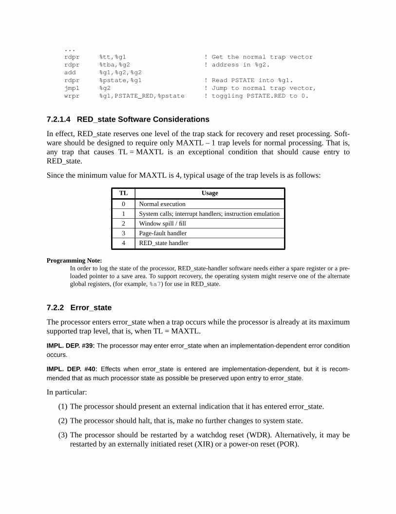
. Soft-at is,y to
r a pre-lternate
ximum
y be
...rdpr %tt,%g1 ! Get the normal trap vectorrdpr %tba,%g2 ! address in %g2.add %g1,%g2,%g2rdpr %pstate,%g1 ! Read PSTATE into %g1.jmpl %g2 ! Jump to normal trap vector,wrpr %g1,PSTATE_RED,%pstate ! toggling PSTATE.RED to 0.
7.2.1.4 RED_state Software Considerations
In effect, RED_state reserves one level of the trap stack for recovery and reset processingware should be designed to require only MAXTL – 1 trap levels for normal processing. Thany trap that causes TL = MAXTL is an exceptional condition that should cause entrRED_state.
Since the minimum value for MAXTL is 4, typical usage of the trap levels is as follows:
Programming Note:In order to log the state of the processor, RED_state-handler software needs either a spare register oloaded pointer to a save area. To support recovery, the operating system might reserve one of the aglobal registers, (for example,%a7) for use in RED_state.
7.2.2 Error_state
The processor enters error_state when a trap occurs while the processor is already at its masupported trap level, that is, when TL = MAXTL.
IMPL. DEP. #39: The processor may enter error_state when an implementation-dependent error conditionoccurs.
IMPL. DEP. #40: Effects when error_state is entered are implementation-dependent, but it is recom-mended that as much processor state as possible be preserved upon entry to error_state.
In particular:
(1) The processor should present an external indication that it has entered error_state.
(2) The processor should halt, that is, make no further changes to system state.
(3) The processor should be restarted by a watchdog reset (WDR). Alternatively, it marestarted by an externally initiated reset (XIR) or a power-on reset (POR).
TL Usage
0 Normal execution
1 System calls; interrupt handlers; instruction emulation
2 Window spill / fill
3 Page-fault handler
4 RED_state handler

ith TLtry intoused
tateditions
nPC
n.
n (PC
ting a
After a reset that brings the processor out of error_state, the processor enters RED_state wset as defined in table 18 on page 130; the trap state describes the state at the time of enerror_state. In particular, for WDR and XIR, TT is set to the value of the original trap that caentry to error_state, not the normal TT value for the WDR or XIR.
7.3 Trap Categories
An exception or interrupt request can cause any of the following trap types:
— A precise trap
— A deferred trap
— A disrupting trap
— A reset trap
7.3.1 Precise Traps
A precise trap is induced by a particular instruction and occurs before any program-visible shas been changed by the trap-inducing instruction. When a precise trap occurs, several conmust be true.
— The PC saved in TPC[TL] points to the instruction that induced the trap, and thesaved in NTPC[TL] points to the instruction that was to be executed next.
— All instructions issued before the one that induced the trap have completed executio
— Any instructions issued after the one that induced the trap remain unexecuted.
Programming Note:Among the actions the trap handler software might take after a precise trap are:
— Return to the instruction that caused the trap and reexecute it, by executing a RETRY instructio
← old PC, nPC← old nPC)
— Emulate the instruction that caused the trap and return to the succeeding instruction by execu
DONE instruction (PC← old nPC, nPC← old nPC + 4)
— Terminate the program or process associated with the trap

rredhangedtions.
ed trapferred
en as
e statetruc-rred-
letedue.
ple-caus-rfluous
cution-rn con-
by aes itcutionexe-
isterter-
7.3.2 Deferred Traps
A deferred trap is also induced by a particular instruction, but unlike a precise trap, a defetrap may occur after program-visible state has been changed. Such state may have been cby the execution of either the trap-inducing instruction itself or by one or more other instruc
If an instruction induces a deferred trap and a precise trap occurs simultaneously, the deferrmay not be deferred past the precise trap, except that a floating-point exception may be depast a precise trap.
Associated with a particular deferred-trap implementation, there must exist:
— An instruction that causes a potentially outstanding deferred-trap exception to be taka trap.
— Privileged instructions that access the deferred-trap queues. This queue contains thinformation needed by supervisor software to emulate the deferred-trap-inducing instion, and to resume execution of the trapped instruction stream. See 5.2.13, “IU DefeTrap Queue.”)
Note that resuming execution may require the emulation of instructions that had not compexecution at the time of the deferred trap, that is, those instructions in the deferred-trap que
IMPL. DEP. #32: Whether any deferred traps (and associated deferred-trap queues) are present is imple-mentation-dependent.
Note that to avoid deferred traps entirely, an implementation would need to execute all immented floating-point instructions synchronously with the execution of integer instructions,ing all generated exceptions to be precise. A deferred-trap queue (e.g., FQ) would be supein such an implementation.
Programming Note:Among the actions software can take after a deferred trap are:
— Emulate the instruction that caused the exception, emulate or cause to execute any other exedeferred instructions that were in an associated deferred-trap state queue, and use RETRY to retutrol to the instruction at which the deferred trap was invoked, or
— Terminate the program or process associated with the trap.
7.3.3 Disrupting Traps
A disrupting trap is neither a precise trap nor a deferred trap. A disrupting trap is causedcondition (e.g., an interrupt), rather than directly by a particular instruction; this distinguishfrom precise and deferred traps. When a disrupting trap has been serviced, program exeresumes where it left off. This differentiates disrupting traps from reset traps, which resumecution at the unique reset address.
Disrupting traps are controlled by a combination of the Processor Interrupt Level (PIL) regand the Interrupt Enable (IE) field of PSTATE. A disrupting trap condition is ignored when in
pec-
exe-rruptrtion ofre the
d trappro-nduceneces-g load
s thathey do
sys-
rupts are disabled (PSTATE.IE = 0) or when the condition’s interrupt level is lower than that sified in PIL.
A disrupting trap may be due to either an interrupt request not directly related to a previouslycuted instruction, or to an exception related to a previously executed instruction. Interequests may be either internal or external. An interrupt request can be induced by the assea signal not directly related to any particular processor or memory state. Examples of this aassertion of an “I/O done” signal or setting external interrupt request lines.
A disrupting trap related to an earlier instruction causing an exception is similar to a deferrein that it occurs after instructions following the trap-inducing instruction have modified thecessor or memory state. The difference is that the condition which caused the instruction to ithe trap may lead to unrecoverable errors, since the implementation may not preserve thesary state. An example of this is an ECC data-access error reported after the correspondininstruction has completed.
Disrupting trap conditions should persist until the corresponding trap is taken.
Programming Note:Among the actions that trap-handler software might take after a disrupting trap are:
— Use RETRY to return to the instruction at which the trap was invoked
(PC← old PC, nPC← old nPC), or
— Terminate the program or process associated with the trap.
7.3.4 Reset Traps
A reset trap occurs when supervisor software or the implementation’s hardware determinethe machine must be reset to a known state. Reset traps differ from disrupting traps, since tnot resume execution of the program that was running when the reset trap occurred.
IMPL. DEP. #37: Some of a processor’s behavior during a reset trap is implementation-dependent. See7.6.2, “Special Trap Processing,” for details.
The following reset traps are defined for SPARC-V9:
Software-initiated reset (SIR):Initiated by software by executing the SIR instruction.
Power-on reset (POR):Initiated when power is applied (or reapplied) to the processor.
Watchdog reset (WDR):Initiated in response to error_state or expiration of a watchdog timer.
Externally initiated reset (XIR) :Initiated in response to an external signal. This reset trap is normally used for criticaltem events, such as power failure.

u-
tions,
ctionphicemoryaccess.
or dis-
inter-
7.3.5 Uses of the Trap Categories
The SPARC-V9trap model stipulates that:
(1) Reset traps, exceptsoftware_initiated_reset traps, occur asynchronously to program exection.
(2) When recovery from an exception can affect the interpretation of subsequent instrucsuch exceptions shall be precise. These exceptions are:
— software_initiated_reset
— instruction_access_exception
— privileged_action
— privileged_opcode
— trap_instruction
— instruction_access_error
— clean_window
— fp_disabled
— LDDF_mem_address_not_aligned
— STDF_mem_address_not_aligned
— tag_overflow
— unimplemented_LDD
— unimplemented_STD
— spill_n_normal
— spill_n_other
— fill_n_normal
— fill_n_other
(3) IMPL. DEP. #33: Exceptions that occur as the result of program execution may be precise ordeferred, although it is recommended that such exceptions be precise. Examples:mem_address_not_aligned, division_by_zero.
(4) An exception caused after the initial access of a multiple-access load or store instru(load-store doubleword, LDSTUB, CASA, CASXA, or SWAP) that causes a catastroexception may be precise, deferred, or disrupting. Thus, a trap due to the second maccess can occur after the processor or memory state has been modified by the first
(5) Implementation-dependent catastrophic exceptions may cause precise, deferred,rupting traps (impl. dep. #31).
(6) Exceptions caused by external events unrelated to the instruction stream, such asrupts, are disrupting.

uction
. Anto
C hasctions.on as
com-ons formayinto
dis-he dis-
traptinationy the
, antore)
hat canrovoke
mighting
For the purposes of this subsection, we must distinguish between the dispatch of an instrand its execution by some functional unit. An instruction is deemed to have beendispatchedwhen the software-visible PC advances beyond that instruction in the instruction streaminstruction is deemed to have beenexecutedwhen the results of that instruction are availablesubsequent instructions.
For most instructions, dispatch and execution appear to occur simultaneously; when the Padvanced beyond the instruction, its results are immediately available to subsequent instruFor floating-point instructions, however, the PC may advance beyond the instruction as sothe IU places the instruction into a floating-point queue; the instruction itself may not havepleted (or even begun) execution, and results may not be available to subsequent instructisome time. In particular, the fact that a floating-point instruction will generate an exceptionnot be noticed by the hardware until additional floating-point instructions have been placedthe queue by the IU. This creates the condition for a deferred trap.
A deferred trap may occur one or more instructions after the trap-inducing instruction ispatched. However, a deferred trap must occur before the execution (but not necessarily tpatch) of any instruction that depends on the trap-inducing instruction. That is, a deferredmay not be deferred past the execution of an instruction that specifies source registers, desregisters, condition codes, or any software-visible machine state that could be modified btrap-inducing instruction.
In the case of floating-point instructions, if a floating-point exception is currently deferredattempt to dispatch a floating-point instruction (FPop, FBfcc, FBPfcc, or floating-point load/sinvokes or causes the outstandingfp_exception_ieee_754 trap.
Implementation Note:To provide the capability to terminate a user process on the occurrence of a catastrophic exception tcause a deferred or disrupting trap, an implementation should provide one or more instructions that pan outstanding exception to be taken as a trap. For example, an outstanding floating-point exceptioncause anfp_exception_ieee_754 trap when any of an FPop, load or store floating-point register (includthe FSR), FBfcc, or FBPfcc instruction is executed.

ister
EF)aps.
trap
per-
rruptrruptsts,
a
7.4 Trap Control
Several registers control how any given trap is processed:
— The interrupt enable (IE) field in PSTATE and the processor interrupt level (PIL) regcontrol interrupt processing.
— The enable floating-point unit (FEF) field in FPRS, the floating-point unit enable (Pfield in PSTATE, and the trap enable mask (TEM) in the FSR control floating-point tr
— The TL register, which contains the current level of trap nesting, controls whether acauses entry to execute_state, RED_state, or error_state.
— PSTATE.TLE determines whether implicit data accesses in the trap routine will beformed using the big- or little-endian byte order.
7.4.1 PIL Control
Between the execution of instructions, the IU prioritizes the outstanding exceptions and interequests according to table 15. At any given time, only the highest priority exception or interequest is taken as a trap.1 When there are multiple outstanding exceptions or interrupt reque
1. The highest priority exception or interrupt is the one with the lowest priority value in table 15. For example,priority 2 exception is processed before a priority 3 exception.

cep-
terruptinter-
-iated
R’s
trap-of TL
ctor.0, are
SPARC-V9 assumes that lower-priority interrupt requests will persist and lower-priority extions will recur if an exception-causing instruction is reexecuted.
For interrupt requests, the IU compares the interrupt request level against the processor inlevel (PIL) register. If the interrupt request level is greater than PIL, the processor takes therupt request trap, assuming there are no higher-priority exceptions outstanding
IMPL. DEP. #34: How quickly a processor responds to an interrupt request and the method by which aninterrupt request is removed are implementation-dependent.
7.4.2 TEM Control
The occurrence of floating-point traps of typeIEEE_754_exception can be controlled with the useraccessible trap enable mask (TEM) field of the FSR. If a particular bit of TEM is 1, the assocIEEE_754_exception can cause anfp_exception_ieee_754 trap.
If a particular bit of TEM is 0, the associatedIEEE_754_exception does not cause anfp_exception_ieee_754 trap. Instead, the occurrence of the exception is recorded in the FSaccrued exception field (aexc).
If an IEEE_754_exception results in anfp_exception_ieee_754 trap, then the destinationf register,fccn, andaexcfields remain unchanged. However, if anIEEE_754_exception does not result in a
trap, then thef register,fccn, andaexc fields are updated to their new values.
7.5 Trap-Table Entry Addresses
Privileged software initializes the trap base address (TBA) register to the upper 49 bits of thetable base address. Bit 14 of the vector address (the “TL>0” field) is set based on the valueat the time the trap is taken; that is, to 0 if TL = 0 and to 1 if TL > 0. Bits 13..5 of the trap veaddress are the contents of the TT register. The lowest five bits of the trap address, bits 4.always 0 (hence each trap-table entry is at least 25 or 32 bytes long). Figure 39 illustrates this.
Figure 39—Trap Vector Address
63 15 14 0
TBA<63:15>
13 45
TL>0 TTTL 00000
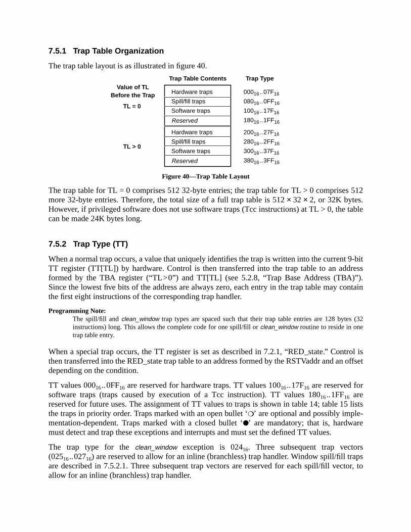
512
table
9-bitress
”).ontain
s (32
trol isn offset
5 lists
sapstor, to
7.5.1 Trap Table Organization
The trap table layout is as illustrated in figure 40.
Figure 40—Trap Table Layout
The trap table for TL = 0 comprises 512 32-byte entries; the trap table for TL > 0 comprisesmore 32-byte entries. Therefore, the total size of a full trap table is 512× 32 × 2, or 32K bytes.However, if privileged software does not use software traps (Tcc instructions) at TL > 0, thecan be made 24K bytes long.
7.5.2 Trap Type (TT)
When a normal trap occurs, a value that uniquely identifies the trap is written into the currentTT register (TT[TL]) by hardware. Control is then transferred into the trap table to an addformed by the TBA register (“TL>0”) and TT[TL] (see 5.2.8, “Trap Base Address (TBA)Since the lowest five bits of the address are always zero, each entry in the trap table may cthe first eight instructions of the corresponding trap handler.
Programming Note:The spill/fill and clean_window trap types are spaced such that their trap table entries are 128 byteinstructions) long. This allows the complete code for one spill/fill orclean_window routine to reside in onetrap table entry.
When a special trap occurs, the TT register is set as described in 7.2.1, “RED_state.” Conthen transferred into the RED_state trap table to an address formed by the RSTVaddr and adepending on the condition.
TT values 00016..0FF16 are reserved for hardware traps. TT values 10016..17F16 are reserved forsoftware traps (traps caused by execution of a Tcc instruction). TT values 18016..1FF16 arereserved for future uses. The assignment of TT values to traps is shown in table 14; table 1the traps in priority order. Traps marked with an open bullet ‘❍’ are optional and possibly imple-mentation-dependent. Traps marked with a closed bullet ‘●’ are mandatory; that is, hardwaremust detect and trap these exceptions and interrupts and must set the defined TT values.
The trap type for theclean_window exception is 02416. Three subsequent trap vector(02516..02716) are reserved to allow for an inline (branchless) trap handler. Window spill/fill trare described in 7.5.2.1. Three subsequent trap vectors are reserved for each spill/fill vecallow for an inline (branchless) trap handler.
Value of TLBefore the Trap
Trap Table Contents Trap Type
TL = 0
Hardware traps
Spill/fill traps
Software traps
Reserved
00016..07F16
08016..0FF16
10016..17F16
18016..1FF16
TL > 0
Hardware traps
Spill/fill traps
Software traps
Reserved
20016..27F16
28016..2FF16
30016..37F16
38016..3FF16

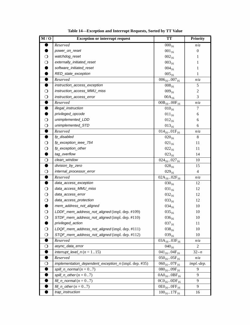
Table 14—Exception and Interrupt Requests, Sorted by TT Value
M / O Exception or interrupt request TT Priority
● Reserved 00016 n/a
● power_on_reset 00116 0
❍ watchdog_reset 00216 1
❍ externally_initiated_reset 00316 1
● software_initiated_reset 00416 1
● RED_state_exception 00516 1
● Reserved 00616..00716 n/a
● instruction_access_exception 00816 5
❍ instruction_access_MMU_miss 00916 2
❍ instruction_access_error 00A16 3
● Reserved 00B16..00F16 n/a
● illegal_instruction 01016 7
● privileged_opcode 01116 6
❍ unimplemented_LDD 01216 6
❍ unimplemented_STD 01316 6
● Reserved 01416..01F16 n/a
● fp_disabled 02016 8
❍ fp_exception_ieee_754 02116 11
❍ fp_exception_other 02216 11
● tag_overflow 02316 14
❍ clean_window 02416..02716 10
● division_by_zero 02816 15
❍ internal_processor_error 02916 4
● Reserved 02A16..02F16 n/a
● data_access_exception 03016 12
❍ data_access_MMU_miss 03116 12
❍ data_access_error 03216 12
❍ data_access_protection 03316 12
● mem_address_not_aligned 03416 10
❍ LDDF_mem_address_not_aligned (impl. dep. #109) 03516 10
❍ STDF_mem_address_not_aligned (impl. dep. #110) 03616 10
● privileged_action 03716 11
❍ LDQF_mem_address_not_aligned (impl. dep. #111) 03816 10
❍ STQF_mem_address_not_aligned (impl. dep. #112) 03916 10
● Reserved 03A16..03F16 n/a
❍ async_data_error 04016 2
● interrupt_level_n (n = 1..15) 04116..04F16 32–n
● Reserved 05016..05F16 n/a
❍ implementation_dependent_exception_n (impl. dep. #35) 06016..07F16 impl.-dep.
● spill_n_normal (n = 0..7) 08016..09F16 9
● spill_n_other (n = 0..7) 0A016..0BF16 9
● fill_n_normal (n = 0..7) 0C016..0DF16 9
● fill_n_other (n = 0..7) 0E016..0FF16 9
● trap_instruction 10016..17F16 16
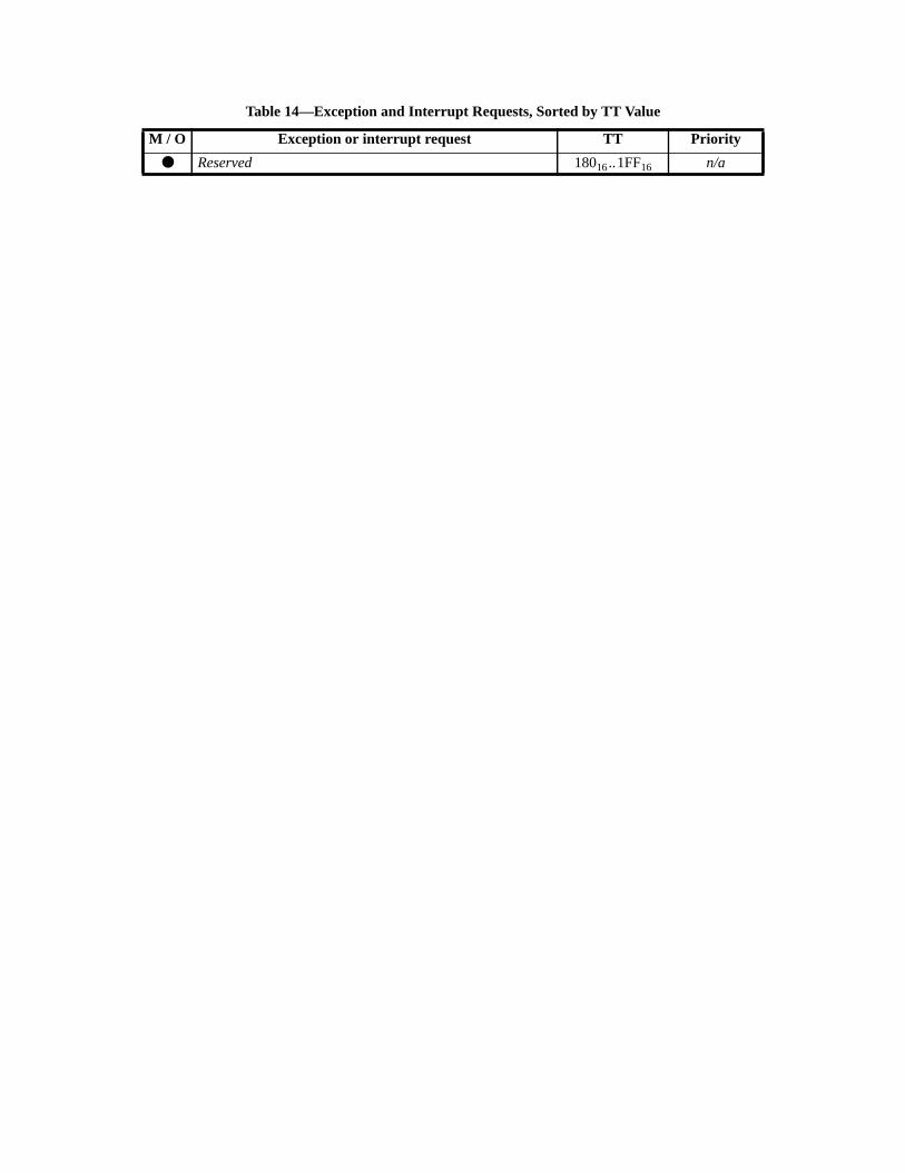
● Reserved 18016..1FF16 n/a
Table 14—Exception and Interrupt Requests, Sorted by TT Value
M / O Exception or interrupt request TT Priority


Table 15—Exception and Interrupt Requests, Sorted by Priority (0 = Highest; 31 = Lowest)
M / O Exception or Interrupt Request TT Priority
● power_on_reset 00116 0
❍ watchdog_reset 00216 1
❍ externally_initiated_reset 00316 1
● software_initiated_reset 00416 1
● RED_state_exception 00516 1
❍ instruction_access_MMU_miss 00916 2
❍ async_data_error 04016 2
❍ instruction_access_error 00A16 3
❍ internal_processor_error 02916 4
● instruction_access_exception 00816 5
● privileged_opcode 01116 6
❍ unimplemented_LDD 01216 6
❍ unimplemented_STD 01316 6
● illegal_instruction 01016 7
● fp_disabled 02016 8
● spill_n_normal (n = 0..7) 08016..09F16 9
● spill_n_other (n = 0..7) 0A016..0BF16 9
● fill_n_normal (n = 0..7) 0C016..0DF16 9
● fill_n_other (n = 0..7) 0E016..0FF16 9
❍ clean_window 02416..02716 10
● mem_address_not_aligned 03416 10
❍ LDDF_mem_address_not_aligned (impl. dep. #109) 03516 10
❍ STDF_mem_address_not_aligned (impl. dep. #110) 03616 10
❍ LDQF_mem_address_not_aligned (impl. dep. #111) 03816 10
❍ STQF_mem_address_not_aligned (impl. dep. #112) 03916 10
❍ fp_exception_ieee_754 02116 11
❍ fp_exception_other 02216 11
● privileged_action 03716 11
● data_access_exception 03016 12
❍ data_access_MMU_miss 03116 12
❍ data_access_error 03216 12
❍ data_access_protection 03316 12
● tag_overflow 02316 14
● division_by_zero 02816 15
● trap_instruction 10016..17F16 16
● interrupt_level_n (n = 1..15) 04116..04F16 32–n
❍ implementation_dependent_exception_n (impl. dep. #35) 06016..07F16 impl.-dep.

h, in ar gen-h this
ses andaddi-
n-
c-
WIN
errupt
ior-
Compatibility Note:Support for some trap types is optional because they are associated with specific instruction(s), whicgiven implementation, might be implemented purely in software. In such a case, hardware would neveerate that type of trap; therefore, support for it would be superfluous. Examples of trap types to whicapplies arefp_exception_ieee_754 and fp_exception_other.
Since the assignment of exceptions and interrupt requests to particular trap vector addresthe priority levels are not visible to a user program, an implementation is allowed to definetional hardware traps.
IMPL. DEP. #35: TT values 06016 TO 07F16 are reserved for implementation-dependent exceptions. Theexistence of implementation_dependent_n traps and whether any that do exist are precise, deferred, ordisrupting is implementation-dependent. See Appendix C, “SPARC-V9 Implementation Dependecies.”
Trap Type values marked “Reserved” in table 14 are reserved for future versions of the architeture.
7.5.2.1 Trap Type for Spill/Fill Traps
The trap type for window spill/fill traps is determined based on the contents of the OTHERand WSTATE registers as follows:
The fields have the following values:
SPILL_OR_FILL :0102 for spill traps; 0112 for fill traps
OTHER :(OTHERWIN≠0)
WTYPE :If (OTHER) then WSTATE.OTHER else WSTATE.NORMAL
7.5.3 Trap Priorities
Table 14 shows the assignment of traps to TT values and the relative priority of traps and intrequests. Priority 0 is highest, priority 31 is lowest; that is, ifX < Y, a pending exception or inter-rupt request with priorityX is taken instead of a pending exception or interrupt request with prity Y.
IMPL. DEP. #36: The priorities of particular traps are relative and are implementation-dependent, becausea future version of the architecture may define new traps, and an implementation may define implementa-tion-dependent traps that establish new relative priorities.
Trap Type
05 2
0SPILL_OR_FILL
1468
0WTYPEOTHER
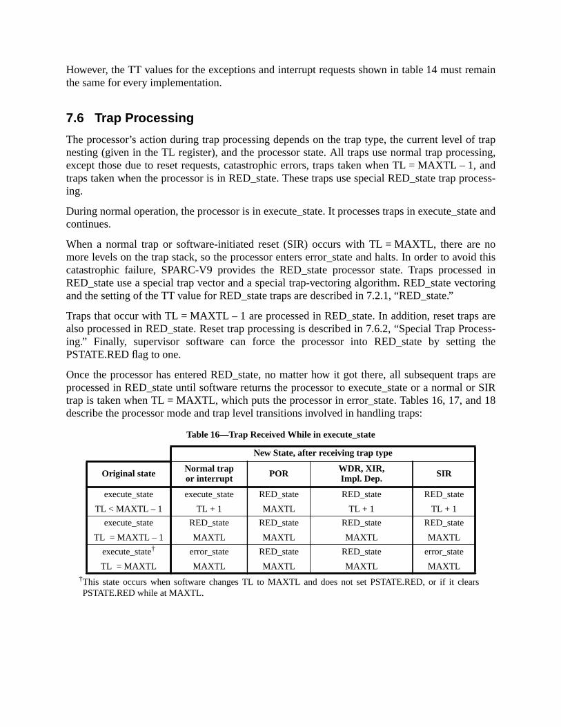
emain
of trapssing,1, androcess-
tate and
nooid thissed inctoring
s arerocess-
the
aps areor SIRd 18
However, the TT values for the exceptions and interrupt requests shown in table 14 must rthe same for every implementation.
7.6 Trap Processing
The processor’s action during trap processing depends on the trap type, the current levelnesting (given in the TL register), and the processor state. All traps use normal trap proceexcept those due to reset requests, catastrophic errors, traps taken when TL = MAXTL –traps taken when the processor is in RED_state. These traps use special RED_state trap ping.
During normal operation, the processor is in execute_state. It processes traps in execute_scontinues.
When a normal trap or software-initiated reset (SIR) occurs with TL = MAXTL, there aremore levels on the trap stack, so the processor enters error_state and halts. In order to avcatastrophic failure, SPARC-V9 provides the RED_state processor state. Traps procesRED_state use a special trap vector and a special trap-vectoring algorithm. RED_state veand the setting of the TT value for RED_state traps are described in 7.2.1, “RED_state.”
Traps that occur with TL = MAXTL – 1 are processed in RED_state. In addition, reset trapalso processed in RED_state. Reset trap processing is described in 7.6.2, “Special Trap Ping.” Finally, supervisor software can force the processor into RED_state by settingPSTATE.RED flag to one.
Once the processor has entered RED_state, no matter how it got there, all subsequent trprocessed in RED_state until software returns the processor to execute_state or a normaltrap is taken when TL = MAXTL, which puts the processor in error_state. Tables 16, 17, andescribe the processor mode and trap level transitions involved in handling traps:
†This state occurs when software changes TL to MAXTL and does not set PSTATE.RED, or if it clearsPSTATE.RED while at MAXTL.
Table 16—Trap Received While in execute_state
New State, after receiving trap type
Original state Normal trapor interrupt POR WDR, XIR,
Impl. Dep. SIR
execute_state
TL < MAXTL – 1
execute_state
TL + 1
RED_state
MAXTL
RED_state
TL + 1
RED_state
TL + 1
execute_state
TL = MAXTL – 1
RED_state
MAXTL
RED_state
MAXTL
RED_state
MAXTL
RED_state
MAXTL
execute_state†
TL = MAXTL
error_state
MAXTL
RED_state
MAXTL
RED_state
MAXTL
error_state
MAXTL

unless
value,and
at its.2.2,
isters
Implementation Note:The processor shall not recognize interrupts while it is in error_state.
7.6.1 Normal Trap Processing
A normal trap causes the following state changes to occur:
— If the processor is already in RED_state, the new trap is processed in RED_stateTL = MAXTL. See 7.6.2.6, “Normal Traps When the Processor is in RED_state.”
— If the processor is in execute_state and the trap level is one less than its maximumthat is, TL = MAXTL–1, the processor enters RED_state. See 7.2.1, “RED_state,”7.6.2.1, “Normal Traps with TL = MAXTL – 1.”
— If the processor is in either execute_state or RED_state, and the trap level is alreadymaximum value, that is, TL = MAXTL, the processor enters error_state. See 7“Error_state.”
Otherwise, the trap uses normal trap processing, and the following state changes occur:
— The trap level is set. This provides access to a fresh set of privileged trap-state regused to save the current state, in effect, pushing a frame on the trap stack.TL ← TL + 1
Table 17—Trap Received While in RED_state
New State, after receiving trap type
Original stateNormal trapor interrupt POR
WDR, XIR,Impl. Dep. SIR
RED_state
TL < MAXTL – 1
RED_state
TL + 1
RED_state
MAXTL
RED_state
TL + 1
RED_state
TL + 1
RED_state
TL = MAXTL – 1
RED_state
MAXTL
RED_state
MAXTL
RED_state
MAXTL
RED_state
MAXTL
RED_state
TL = MAXTL
error_state
MAXTL
RED_state
MAXTL
RED_state
MAXTL
error_state
MAXTL
Table 18—Reset Received While in error_state
New State, after receiving trap type
Original stateNormal trapor interrupt POR
WDR, XIR,Impl. Dep. SIR
error_state
TL < MAXTL – 1—
RED_state
MAXTL
RED_state
TL + 1—
error_state
TL = MAXTL – 1—
RED_state
MAXTL
RED_state
MAXTL—
error_state
TL = MAXTL—
RED_state
MAXTL
RED_state
MAXTL—
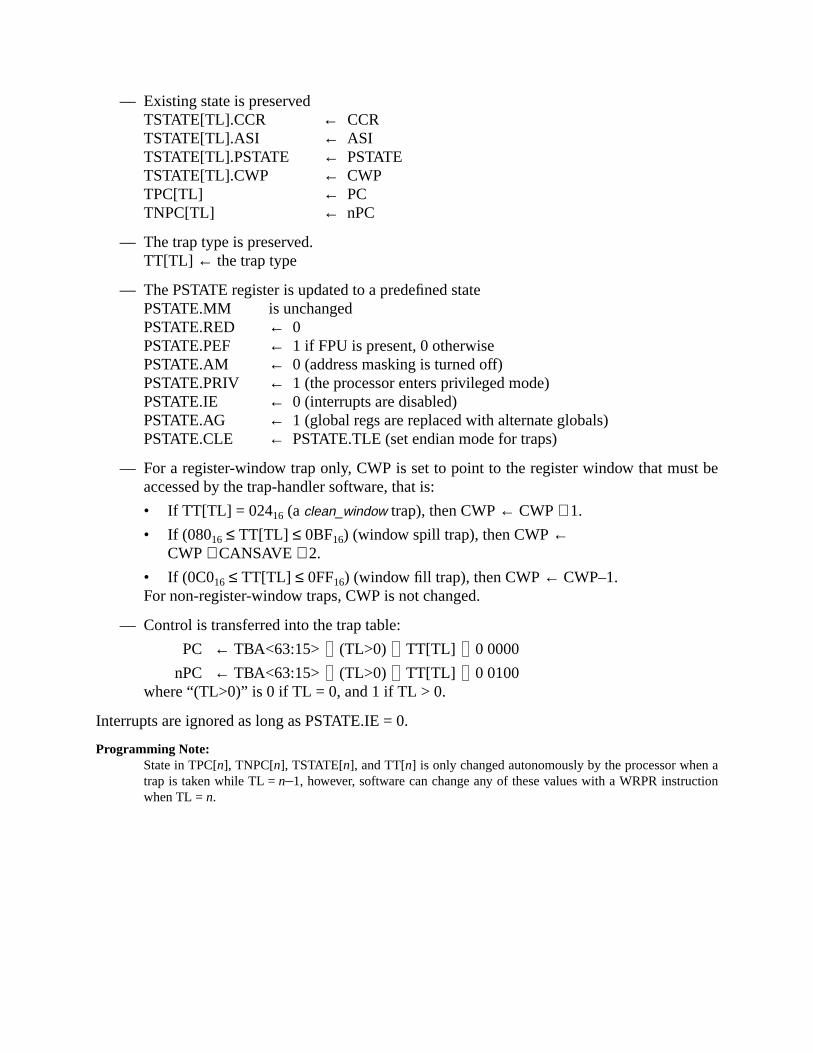
t be
ation
— Existing state is preservedTSTATE[TL].CCR ← CCRTSTATE[TL].ASI ← ASITSTATE[TL].PSTATE ← PSTATETSTATE[TL].CWP ← CWPTPC[TL] ← PCTNPC[TL] ← nPC
— The trap type is preserved.TT[TL] ← the trap type
— The PSTATE register is updated to a predefined statePSTATE.MM is unchangedPSTATE.RED ← 0PSTATE.PEF ← 1 if FPU is present, 0 otherwisePSTATE.AM ← 0 (address masking is turned off)PSTATE.PRIV ← 1 (the processor enters privileged mode)PSTATE.IE ← 0 (interrupts are disabled)PSTATE.AG ← 1 (global regs are replaced with alternate globals)PSTATE.CLE ← PSTATE.TLE (set endian mode for traps)
— For a register-window trap only, CWP is set to point to the register window that musaccessed by the trap-handler software, that is:
• If TT[TL] = 02416 (aclean_window trap), then CWP← CWP+ 1.
• If (08016 ≤ TT[TL] ≤ 0BF16) (window spill trap), then CWP←CWP+ CANSAVE + 2.
• If (0C016 ≤ TT[TL] ≤ 0FF16) (window fill trap), then CWP← CWP–1.For non-register-window traps, CWP is not changed.
— Control is transferred into the trap table:
PC ← TBA<63:15> (TL>0) TT[TL] 0 0000
nPC ← TBA<63:15> (TL>0) TT[TL] 0 0100where “(TL>0)” is 0 if TL = 0, and 1 if TL > 0.
Interrupts are ignored as long as PSTATE.IE = 0.
Programming Note:State in TPC[n], TNPC[n], TSTATE[n], and TT[n] is only changed autonomously by the processor whentrap is taken while TL =n–1, however, software can change any of these values with a WRPR instrucwhen TL =n.

te
7.6.2 Special Trap Processing
The following conditions invoke special trap processing:
— Traps taken with TL = MAXTL – 1
— Power-on reset traps
— Watchdog reset traps
— Externally initiated reset traps
— Software-initiated reset traps
— Traps taken when the processor is already in RED_state
— Implementation-dependent traps
IMPL. DEP. #38: Implementation-dependent registers may or may not be affected by the various resettraps.
7.6.2.1 Normal Traps with TL = MAXTL – 1
Normal traps that occur when TL = MAXTL – 1 are processed in RED_state. The following stachanges occur:
— The trap level is advanced.TL ← MAXTL
— Existing state is preservedTSTATE[TL].CCR ← CCRTSTATE[TL].ASI ← ASITSTATE[TL].PSTATE ← PSTATETSTATE[TL].CWP ← CWPTPC[TL] ← PCTNPC[TL] ← nPC
— The trap type is preserved.TT[TL] ← the trap type
— The PSTATE register is set as follows:PSTATE.MΜ ← 002 (TSO)PSTATE.RED ← 1 (enter RED_state)PSTATE.PEF ← 1 if FPU is present, 0 otherwisePSTATE.AM ← 0 (address masking is turned off)PSTATE.PRIV ← 1 (the processor enters privileged mode)PSTATE.IE ← 0 (interrupts are disabled)PSTATE.AG ← 1 (global regs are replaced with alternate globals)PSTATE.CLE ← PSTATE.TLE (set endian mode for traps)

t be
er-onstate is
— For a register-window trap only, CWP is set to point to the register window that musaccessed by the trap-handler software, that is:
• If TT[TL] = 02416 (aclean_window trap), then CWP← CWP+ 1.
• If (08016 ≤ TT[TL] ≤ 0BF16) (window spill trap), then CWP←CWP+ CANSAVE + 2.
• If (0C016 ≤ TT[TL] ≤ 0FF16)(window fill trap), then CWP← CWP–1.For non-register-window traps, CWP is not changed.
— Implementation-specific state changes; for example, disabling an MMU
— Control is transferred into the RED_state trap table
PC ← RSTVaddr<63:8> 1010 00002
nPC ← RSTVaddr<63:8> 1010 01002
7.6.2.2 Power-On Reset (POR) Traps
Initiated when power is applied to the processor. If the processor is in error_state, a powreset (POR) brings the processor out of error_state and places it in RED_state. Processorundefined after POR, except for the following:
— The trap level is set.TL ← MAXTL
— The trap type is set.TT[TL] ← 00116
— The PSTATE register is set as follows:PSTATE.MM ← 002 (TSO)PSTATE.RED ← 1 (enter RED_state)PSTATE.PEF ← 1 if FPU is present, 0 otherwisePSTATE.AM ← 0 (address masking is turned off)PSTATE.PRIV ← 1 (the processor enters privileged mode)PSTATE.IE ← 0 (interrupts are disabled)PSTATE.AG ← 1 (global regs are replaced with alternate globals)PSTATE.TLE ← 0 (big-endian mode for traps)PSTATE.CLE ← 0 (big-endian mode for non-traps)
— The TICK register is protected.TICK.NPT ← 1 (TICK unreadable by nonprivileged software)
— Implementation-specific state changes; for example, disabling an MMU
— Control is transferred into the RED_state trap table
PC ← RSTVaddr<63:8> 0010 00002
nPC ← RSTVaddr<63:8> 0010 01002

e tod per-
ds andregis-e in ang reset
For any reset when TL = MAXTL, for alln<MAXTL, the values in TPC[n], TNPC[n], andTSTATE[n] are undefined.
7.6.2.3 Watchdog Reset (WDR) Traps
WDR traps are initiated by an external signal. Typically, this is generated in responserror_state or expiration of a watchdog timer. WDR clears error_state and hung states, anforms a system reset; pending and in-progress hardware operations (for example, loastores) may be cancelled or aborted. Architecturally defined registers (e. g., floating-pointters, integer registers, etc.) and state are unchanged from before the WDR, but they may binconsistent state if operations are aborted. If the processor is in error_state, a watchdo(WDR) brings the processor out of error_state and places it in RED_state.
The following state changes occur:
— The trap level is set.TL ← MIN(TL + 1, MAXTL)
— Existing state is preserved.TSTATE[TL].CCR ← CCRTSTATE[TL].ASI ← ASITSTATE[TL].PSTATE ← PSTATETSTATE[TL].CWP ← CWPTPC[TL] ← PCTNPC[TL] ← nPC
— TT[TL] is set as described below.
— The PSTATE register is set as follows:PSTATE.MM ← 002 (TSO)PSTATE.RED ← 1 (enter RED_state)PSTATE.PEF ← 1 if FPU is present, 0 otherwisePSTATE.AM ← 0 (address masking is turned off)PSTATE.PRIV ← 1 (the processor enters privileged mode)PSTATE.IE ← 0 (interrupts are disabled)PSTATE.AG ← 1 (global regs are replaced with alternate globals)PSTATE.CLE ← PSTATE.TLE (set endian mode for traps)
— Implementation-specific state changes; for example, disabling an MMU.
— Control is transferred into the RED_state trap table.
PC ← RSTVaddr<63:8> 0100 00002
nPC ← RSTVaddr<63:8> 0100 01002

of theor in
askedbut-pera-rnally
If a watchdog reset occurs when the processor is in error_state, the TT field gives the typetrap that caused entry into error_state. If a watchdog reset occurs with the processexecute_state, TT is set to 2 (WDR).
For any reset when TL = MAXTL, for alln<MAXTL, the values in TPC[n], TNPC[n], andTSTATE[n] are undefined.
7.6.2.4 Externally Initiated Reset (XIR) Traps
XIR traps are initiated by an external signal. They behave like an interrupt that cannot be mby IE = 0 or PIL. Typically, XIR is used for critical system events such as power failure, resetton pressed, failure of external components that does not require a WDR (which aborts otions), or system-wide reset in a multiprocessor. If the processor is in error_state, an exteinitiated reset (XIR) brings the processor out of error_state and places it in RED_state.
The following state changes occur:
— The trap level is set.TL ← MIN(TL + 1, MAXTL)
— Existing state is preserved.TSTATE[TL].CCR ← CCRTSTATE[TL].ASI ← ASITSTATE[TL].PSTATE ← PSTATETSTATE[TL].CWP ← CWPTPC[TL] ← PCTNPC[TL] ← nPC
— TT[TL] is set as described below.
— The PSTATE register is set as follows:PSTATE.MM ← 002 (TSO)PSTATE.RED ← 1 (enter RED_state)PSTATE.PEF ← 1 if FPU is present, 0 otherwisePSTATE.AM ← 0 (address masking is turned off)PSTATE.PRIV ← 1 (the processor enters privileged mode)PSTATE.IE ← 0 (interrupts are disabled)PSTATE.AG ← 1 (global regs are replaced with alternate globals)PSTATE.CLE ← PSTATE.TLE (set endian mode for traps)
— Implementation-specific state changes; for example, disabling an MMU.
— Control is transferred into the RED_state trap table.
PC ← RSTVaddr<63:8> 0110 00002
nPC ← RSTVaddr<63:8> 0110 01002

hen theXIR
as a
TT is set in the same manner as for watchdog reset. If the processor is in execute_state wexternally initiated reset (XIR) occurs, TT = 3. If the processor is in error_state when theoccurs, TT identifies the exception that caused entry into error_state.
For any reset when TL = MAXTL, for alln<MAXTL, the values in TPC[n], TNPC[n], andTSTATE[n] are undefined.
7.6.2.5 Software-Initiated Reset (SIR) Traps
SIR traps are initiated by executing an SIR instruction. This is used by supervisor softwarepanic operation, or a meta-supervisor trap.
The following state changes occur:
— If TL = MAXTL, then enter error_state. Otherwise, do the following:
— The trap level is set.TL ← TL + 1
— Existing state is preservedTSTATE[TL].CCR ← CCRTSTATE[TL].ASI ← ASITSTATE[TL].PSTATE ← PSTATETSTATE[TL].CWP ← CWPTPC[TL] ← PCTNPC[TL] ← nPC
— The trap type is set.TT[TL] ← 0416
— The PSTATE register is set as follows:PSTATE.MM ← 002 (TSO)PSTATE.RED ← 1 (enter RED_state)PSTATE.PEF ← 1 if FPU is present, 0 otherwisePSTATE.AM ← 0 (address masking is turned off)PSTATE.PRIV ← 1 (the processor enters privileged mode)PSTATE.IE ← 0 (interrupts are disabled)PSTATE.AG ← 1 (global regs are replaced with alternate globals)PSTATE.CLE ← PSTATE.TLE (set endian mode for traps)
— Implementation-specific state changes; for example, disabling an MMU.
— Control is transferred into the RED_state trap table
PC ← RSTVaddr<63:8> 1000 00002
nPC ← RSTVaddr<63:8> 1000 01002

_state,
t be
For any reset when TL = MAXTL, for alln < MAXTL, the values in TPC[n], TNPC[n], andTSTATE[n] are undefined.
7.6.2.6 Normal Traps When the Processor is in RED_state
Normal traps taken when the processor is already in RED_state are also processed in REDunless TL = MAXTL, in which case the processor enters error_state.
The processor state shall be set as follows:
— The trap level is set.TL ← TL + 1
— Existing state is preserved.TSTATE[TL].CCR ← CCRTSTATE[TL].ASI ← ASITSTATE[TL].PSTATE ← PSTATETSTATE[TL].CWP ← CWPTPC[TL] ← PCTNPC[TL] ← nPC
— The trap type is preserved.TT[TL] ← trap type
— The PSTATE register is set as follows:PSTATE.MM ← 002 (TSO)PSTATE.RED ← 1 (enter RED_state)PSTATE.PEF ← 1 if FPU is present, 0 otherwisePSTATE.AM ← 0 (address masking is turned off)PSTATE.PRIV ← 1 (the processor enters privileged mode)PSTATE.IE ← 0 (interrupts are disabled)PSTATE.AG ← 1 (global regs are replaced with alternate globals)PSTATE.CLE ← PSTATE.TLE (set endian mode for traps)
— For a register-window trap only, CWP is set to point to the register window that musaccessed by the trap-handler software, that is:
• If TT[TL] = 02416 (aclean_window trap), then CWP← CWP+ 1.
• If (08016 ≤ TT[TL] ≤ 0BF16) (window spill trap), thenCWP← CWP+ CANSAVE + 2.
• If (0C016 ≤ TT[TL] ≤ 0FF16) (window fill trap), then CWP← CWP – 1.For non-register-window traps, CWP is not changed.
— Implementation-specific state changes; for example, disabling an MMU
— Control is transferred into the RED_state trap table
PC ← RSTVaddr<63:8> 1010 00002
nPC ← RSTVaddr<63:8> 1010 01002

condi-ap type-e-eptioneach
curredn anded the
from
this
ple, a. dep.
e was
pagertual
7.6.2.7 Implementation-Dependent Traps
The operation of the processor forimplementation_dependent_exception_n traps is implementation-dependent (impl. dep. #35).
7.7 Exception and Interrupt Descriptions
The following paragraphs describe the various exceptions and interrupt requests and thetions that cause them. Each exception and interrupt request describes the corresponding tras defined by the trap model. An open bullet ‘❍’ identifies optional and possibly implementationdependent traps; traps marked with a closed bullet ‘●’ are mandatory. Each trap is marked as prcise, deferred, disrupting, or reset. Example exception conditions are included for each exctype. Appendix A, “Instruction Definitions,” enumerates which traps can be generated byinstruction.
❍ async_data_error [tt = 04016] (Disrupting)An asynchronous data error occurred on a data access. Examples: an ECC error ocwhile writing data from a cache store buffer to memory, or an ECC error occurred oMMU hardware table walk. When anasync_data_error occurs, the TPC and TNPC stackeby the trap are not necessarily related to the instruction or data access that causerror; that is,async_data_error causes a disrupting trap.
Compatibility Note:The SPARC-V9async_data_error exception supersedes the less general SPARC-V8data_store_errorexception.
❍ clean_window [tt = 02416..02716] (Precise)A SAVE instruction discovered that the window about to be used contains dataanother address space; the window must be cleaned before it can be used.
IMPL. DEP. #102: An implementation may choose either to implement automatic cleaning of regis-ter windows in hardware, or to generate a clean_window trap, when needed, so that window(s) canbe cleaned by software. If an implementation chooses the latter option, then support fortrap type is mandatory.
❍ data_access_error [tt = 03216] (Precise, Deferred, or Disrupting)A catastrophic error exception occurred on a data access from/to memory (for examparity error on a data cache access, or an uncorrectable ECC memory error) (impl#31).
● data_access_exception [tt = 03016] (Precise or Deferred)An exception occurred on a data access. For example, an MMU indicated that a paginvalid or protected (impl. dep. #33).
❍ data_access_MMU_miss [tt = 03116] (Precise or Deferred)A miss in an MMU occurred on a data access from/to memory. For example, adescriptor cache or translation lookaside buffer did not contain a translation for the viaddress. (impl. dep. #33)

page
power
win-
load/.
nable
nce or’s
ILL-ulderate
parity
❍ data_access_protection [tt = 03316] (Precise or Deferred)A protection fault occurred on a data access; for example, an MMU indicated that thewas write-protected (impl. dep. #33).
● division_by_zero [tt = 02816] (Precise or Deferred)An integer divide instruction attempted to divide by zero (impl. dep. #33).
❍ externally_initiated_reset [tt = 00316] (Reset)An external signal was asserted. This trap is used for catastrophic events such asfailure, reset button pressed, and system-wide reset in multiprocessor systems.
● fill_n_normal [tt = 0C016..0DF16] (Precise)
● fill_n_other [tt = 0E016..0FF16] (Precise)A RESTORE or RETURN instruction has determined that the contents of a registerdow must be restored from memory.
Compatibility Note:The SPARC-V9 fill_n_* exceptions supersede the SPARC-V8window_underflow exception.
● fp_disabled [tt = 02016] (Precise)An attempt was made to execute an FPop, a floating-point branch, or a floating-pointstore instruction while an FPU was not present, PSTATE.PEF = 0, or FPRS.FEF = 0
❍ fp_exception_ieee_754 [tt = 02116] (Precise or Deferred (impl. dep. #23))An FPop instruction generated an IEEE_754_exception and its corresponding trap emask (TEM) bit was 1. The floating-point exception type,IEEE_754_exception, is encodedin the FSR.ftt, and specificIEEE_754_exception information is encoded in FSR.cexc.
❍ fp_exception_other [tt = 02216] (Precise or Deferred (impl. dep. #23))An FPop instruction generated an exception other than anIEEE_754_exception. For exam-ple, the FPop is unimplemented, or the FPop did not complete, or there was a sequehardware error in the FPU. The floating-point exception type is encoded in the FSRfttfield.
● illegal_instruction [tt = 01016] (Precise or Deferred)An attempt was made to execute an instruction with an unimplemented opcode, anTRAP instruction, an instruction with invalid field usage, or an instruction that woresult in illegal processor state. Note that unimplemented FPop instructions genfp_exception_other traps.
❍ implementation_dependent_exception_n [tt = 06016..07F16] (Pre, Def, or Dis)These exceptions are implementation-dependent (impl. dep. #35).
❍ instruction_access_error [tt = 00A16] (Precise, Deferred, or Disrupting)A catastrophic error exception occurred on an instruction access. For example, aerror on an instruction cache access (impl. dep. #31).
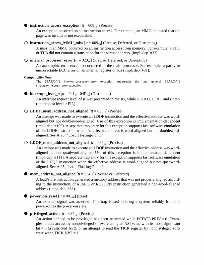
t the
PDC
ity or
V8
r-
word-dent
lationord-
word-dent
lationord-
ccord-ned
the
am-cantoft-
● instruction_access_exception [tt = 00816] (Precise)An exception occurred on an instruction access. For example, an MMU indicated thapage was invalid or not executable.
❍ instruction_access_MMU_miss [tt = 00916] (Precise, Deferred, or Disrupting)A miss in an MMU occurred on an instruction access from memory. For example, aor TLB did not contain a translation for the virtual address. (impl. dep. #33)
❍ internal_processor_error [tt = 02916] (Precise, Deferred, or Disrupting)A catastrophic error exception occurred in the main processor. For example, a paruncorrectable ECC error on an internal register or bus (impl. dep. #31).
Compatibility Note:The SPARC-V9 internal_processor_error exception supersedes the less general SPARC-r_register_access_error exception.
● interrupt_level_n [tt = 04116..04F16] (Disrupting)An interrupt request level ofn was presented to the IU, while PSTATE.IE = 1 and (interupt request level > PIL).
❍ LDDF_mem_address_not_aligned [tt = 03516] (Precise)An attempt was made to execute an LDDF instruction and the effective address wasaligned but not doubleword-aligned. Use of this exception is implementation-depen(impl. dep. #109). A separate trap entry for this exception supports fast software emuof the LDDF instruction when the effective address is word-aligned but not doublewaligned. See A.25, “Load Floating-Point.”
❍ LDQF_mem_address_not_aligned [tt = 03816] (Precise)An attempt was made to execute an LDQF instruction and the effective address wasaligned but not quadword-aligned. Use of this exception is implementation-depen(impl. dep. #111). A separate trap entry for this exception supports fast software emuof the LDQF instruction when the effective address is word-aligned but not quadwaligned. See A.25, “Load Floating-Point.”
● mem_address_not_aligned [tt = 03416] (Precise or Deferred)A load/store instruction generated a memory address that was not properly aligned aing to the instruction, or a JMPL or RETURN instruction generated a non-word-aligaddress (impl. dep. #33).
● power_on_reset [tt = 00116] (Reset)An external signal was asserted. This trap isused to bring a system reliably frompower-off to the power-on state.
● privileged_action [tt = 03716] (Precise)An action defined to be privileged has been attempted while PSTATE.PRIV = 0. Exples: a data access by nonprivileged software using an ASI value with its most signifibit = 0 (a restricted ASI), or an attempt to read the TICK register by nonprivileged sware when TICK.NPT = 1.

-
stem
dow
word-dent
lationord-
word-dent
lationord-
er-
ard-
ard-
● privileged_opcode [tt = 01116] (Precise)An attempt was made to execute a privileged instruction while PSTATE.PRIV = 0.
Compatibility Note:This trap type is identical to the SPARC-V8privileged_instruction trap. The name was changed to distinguish it from the newprivileged_action trap type.
● software_initiated_reset [tt = 00416] (Reset)Caused by the execution of the SIR, Software-Initiated Reset, instruction. It allows sysoftware to reset the processor.
● spill_n_normal [tt = 08016..09F16] (Precise)
● spill_n_other [tt = 0A016..0BF16] (Precise)A SAVE or FLUSHW instruction has determined that the contents of a register winmust be saved to memory.
Compatibility Note:The SPARC-V9 spill_n_* exceptions supersede the SPARC-V8window_overflow exception.
❍ STDF_mem_address_not_aligned [tt = 03616] (Precise)An attempt was made to execute an STDF instruction and the effective address wasaligned but not doubleword-aligned. Use of this exception is implementation-depen(impl. dep. #110). A separate trap entry for this exception supports fast software emuof the STDF instruction when the effective address is word-aligned but not doublewaligned. See A.52, “Store Floating-Point.”
❍ STQF_mem_address_not_aligned [tt = 03916] (Precise)An attempt was made to execute an STQF instruction and the effective address wasaligned but not quadword-aligned. Use of this exception is implementation-depen(impl. dep. #112). A separate trap entry for this exception supports fast software emuof the STQF instruction when the effective address is word-aligned but not quadwaligned. See A.52, “Store Floating-Point.”
● tag_overflow [tt = 02316] (Precise)A TADDccTV or TSUBccTV instruction was executed, and either 32-bit arithmetic ovflow occurred or at least one of the tag bits of the operands was nonzero.
● trap_instruction [tt = 10016..17F16] (Precise)A Tcc instruction was executed and the trap condition evaluated to TRUE.
❍ unimplemented_LDD [tt = 01216] (Precise)An attempt was made to execute an LDD instruction, which is not implemented in hware on this implementation (impl. dep. #107).
❍ unimplemented_STD [tt = 01316] (Precise)An attempt was made to execute an STD instruction which is not implemented in hware on this implementation (impl. dep. #108).
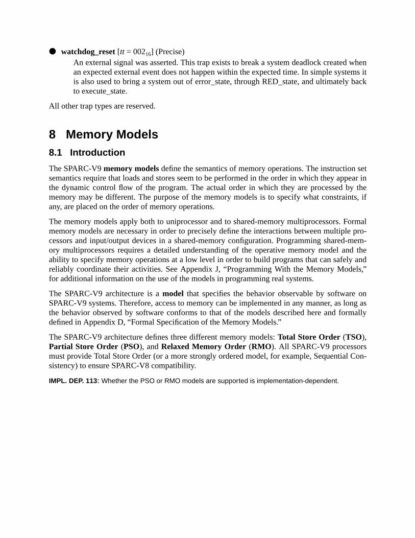
whenems itback
setpear iny thets, if
ormalle pro--mem-nd theandls,”
onlong asrmally
l Con-
● watchdog_reset [tt = 00216] (Precise)An external signal was asserted. This trap exists to break a system deadlock createdan expected external event does not happen within the expected time. In simple systis also used to bring a system out of error_state, through RED_state, and ultimatelyto execute_state.
All other trap types are reserved.
8 Memory Models8.1 Introduction
The SPARC-V9memory modelsdefine the semantics of memory operations. The instructionsemantics require that loads and stores seem to be performed in the order in which they apthe dynamic control flow of the program. The actual order in which they are processed bmemory may be different. The purpose of the memory models is to specify what constrainany, are placed on the order of memory operations.
The memory models apply both to uniprocessor and to shared-memory multiprocessors. Fmemory models are necessary in order to precisely define the interactions between multipcessors and input/output devices in a shared-memory configuration. Programming sharedory multiprocessors requires a detailed understanding of the operative memory model aability to specify memory operations at a low level in order to build programs that can safelyreliably coordinate their activities. See Appendix J, “Programming With the Memory Modefor additional information on the use of the models in programming real systems.
The SPARC-V9 architecture is amodel that specifies the behavior observable by softwareSPARC-V9 systems. Therefore, access to memory can be implemented in any manner, asthe behavior observed by software conforms to that of the models described here and fodefined in Appendix D, “Formal Specification of the Memory Models.”
The SPARC-V9 architecture defines three different memory models:Total Store Order (TSO),Partial Store Order (PSO), andRelaxed Memory Order (RMO ). All SPARC-V9 processorsmust provide Total Store Order (or a more strongly ordered model, for example, Sequentiasistency) to ensure SPARC-V8 compatibility.
IMPL. DEP. 113: Whether the PSO or RMO models are supported is implementation-dependent.

leastly on
rmalmalormal
oryrtialMO,y also
stron-
s-tencyload-
der inquen-nts ansis-
ed inof
bitted bymay be
Figure 41 shows the relationship of the various SPARC-V9 memory models, from therestrictive to the most restrictive. Programs written assuming one model will function correctany included model.
Figure 41—Memory Models from Least Restrictive (RMO) to Most Restrictive (TSO)
SPARC-V9 provides multiple memory models so that:
— Implementations can schedule memory operations for high performance.
— Programmers can create synchronization primitives using shared memory.
These models are described informally in this subsection and formally in Appendix D, “FoSpecification of the Memory Models.” If there is a conflict in interpretation between the infordescription provided here and the formal models, the formal models supersede the infdescription.
There is no preferred memory model for SPARC-V9. Programs written for Relaxed MemOrder will work in Partial Store Order and Total Store Order as well. Programs written for PaStore Order will work in Total Store Order. Programs written for a weak model, such as Rmay execute more quickly, since the model exposes more scheduling opportunities, but marequire extra instructions to ensure synchronization. Multiprocessor programs written for ager model will behave unpredictably if run in a weaker model.
Machines that implementsequential consistency(also called strong ordering or strong consitency) automatically support programs written for TSO, PSO, and RMO. Sequential consisis not a SPARC-V9 memory model. In sequential consistency, the loads, stores, and atomicstores of all processors are performed by memory in a serial order that conforms to the orwhich these instructions are issued by individual processors. A machine that implements setial consistency may deliver lower performance than an equivalent machine that implemeweaker model. Although particular SPARC-V9 implementations may support sequential cotency, portable software must not rely on having this model available.
8.2 Memory, Real Memory, and I/O Locations
Memory is the collection of locations accessed by the load and store instructions (describAppendix A, “Instruction Definitions”). Each location is identified by an address consistingtwo elements: anaddress space identifier(ASI), which identifies an address space, and a 64-address,which is a byte offset into that address space. Memory addresses may be interprethe memory subsystem to be either physical addresses or virtual addresses; addresses
RMO PSO TSO

ntly and
store to
ostd-store
tomicds mayns aree per-rties,
-depen-
y are
th toloca-
ds fol-o theMEM-
re thatrencedsoft-
t in thehoseusing
remapped and values cached, provided that memory properties are preserved transparecoherency is maintained.
When two or more data addresses refer to the same datum, the address is said to bealiased. In thiscase, the processor and memory system must cooperate to maintain consistency; that is, aan aliased address must change all values aliased to that address.
Memory addresses identify either real memory or I/O locations.
Real memory stores information without side effects. A load operation returns the value mrecently stored. Operations are side-effect-free in the sense that a load, store, or atomic loato a location in real memory has no program-observable effect, except upon that location.
I/O locations may not behave like memory and may have side effects. Load, store, and aload-store operations performed on I/O locations may have observable side effects and loanot return the value most recently stored. The value semantics of operations on I/O locationot defined by the memory models, but the constraints on the order in which operations arformed is the same as it would be if the I/O locations were real memory. The storage propecontents, semantics, ASI assignments, and addresses of I/O registers are implementationdent (impl. dep. #6) (impl. dep. #7) (impl. dep. #123).
IMPL. DEP. #118: The manner in which I/O locations are identified is implementation-dependent.
See F.3.2, “Attributes the MMU Associates with Each Mapping,” for example.
IMPL. DEP #120: The coherence and atomicity of memory operations between processors and I/O DMAmemory accesses are implementation-dependent.
Compatibility Note:Operations to I/O locations arenot guaranteed to be sequentially consistent between themselves, as thein SPARC-V8.
SPARC-V9 does not distinguish real memory from I/O locations in terms of ordering. All references, boI/O locations and real memory, conform to the memory model’s order constraints. References to I/Otions may need to be interspersed with MEMBAR instructions to guarantee the desired ordering. Loalowing stores to locations with side effects may return unexpected results due to lookaside intprocessor’s store buffer, which may subsume the memory transaction. This can be avoided by using aBAR #LookAside .
Systems supporting SPARC-V8 applications that use memory mapped I/O locations must ensuSPARC-V8 sequential consistency of I/O locations can be maintained when those locations are refeby a SPARC-V8 application. The MMU either must enforce such consistency or cooperate with systemware and/or the processor to provide it.
IMPL. DEP #121: An implementation may choose to identify certain addresses and use an implementa-tion-dependent memory model for references to them.
For example, an implementation might choose to process addresses tagged with a flag bimemory management unit (see Appendix F, “SPARC-V9 MMU Requirements”), or to treat tthat utilize a particular ASI (see 8.3, “Addressing and Alternate Address Spaces,” below) asa sequentially consistent model.
a 64-lfwordalignedies, andcasesload,ranteedrentrences
lewordd usingnd storeword-rity of
several
to be
ssingerence
mory
eto thess to a
fullyfinedcted
d per-,
8.3 Addressing and Alternate Address SpacesAn address in SPARC-V9 is a tuple consisting of an 8-bit address space identifier (ASI) andbit byte-address offset in the specified address space. Memory is byte-addressed, with haaccesses aligned on 2-byte boundaries, word accesses (which include instruction fetches)on 4-byte boundaries, extended-word and doubleword accesses aligned on 8-byte boundarquadword quantities aligned on 16-byte boundaries. With the possible exception of thedescribed in 6.3.1.1, “Memory Alignment Restrictions,” an improperly aligned address in astore, or load-store instruction always causes a trap to occur. The largest datum that is guato be atomically read or written is an aligned doubleword. Also, memory references to diffebytes, halfwords, and words in a given doubleword are treated for ordering purposes as refeto the same location. Thus, the unit of ordering for memory is a doubleword.
Programming Note:While the doubleword is the coherency unit for update, programmers should not assume that doubfloating-point values are updated as a unit unless they are doubleword-aligned and always updatedouble-precision loads and stores. Some programs use pairs of single-precision operations to load adouble-precision floating-point values when the compiler cannot determine that they are doublealigned. Also, while quad-precision operations are defined in the SPARC-V9 architecture, the granulaloads and stores for quad-precision floating-point values may be word or doubleword.
The processor provides an address space identifier with every address. This ASI may servepurposes:
— To identify which of several distinguished address spaces the 64-bit address offset isinterpreted as addressing
— To provide additional access control and attribute information, for example, the procewhich is to be taken if an access fault occurs or to specify the endian-ness of the ref
— To specify the address of an internal control register in the processor, cache, or memanagement hardware
The memory management hardware can associate an independent 264-byte memory address spacwith each ASI. If this is done, it becomes possible to allow system software easy accessaddress space of the faulting program when processing exceptions, or to implement acceclient program’s memory space by a server program.
The architecturally specified ASIs are listed in table 12 on page 75. ASIs need not bedecoded by the hardware (impl. dep. #30). In particular, specifying an architecturally undeASI value in a memory reference instruction or in the ASI register may produce unexpeimplementation-dependent results.
When TL = 0, normal accesses by the processor to memory when fetching instructions anforming loads and stores implicitly specify ASI_PRIMARY or ASI_PRIMARY_LITTLEdepending on the setting of the PSTATE.CLE bit.
IMPL. DEP. #124: When TL > 0, the implicit ASI for instruction fetches, loads, and stores is implementa-tion-dependent.

o noton-
sses, thefrom
ndentuire
e theirshown
ndft-
strictedictedro-
bebina-om-
uardThe
strophice hard-
result.et to
able toNULL
ultinglts.
C-V9ix F,
Implementation Note:Implementations that support the nucleus context should use ASI_NUCLEUS{_LITTLE}; those that dshould use ASI_PRIMARY{_LITTLE}. See F.4.4, “Contexts,” for more information about the nucleus ctext.
Accesses to other address spaces use the load/store alternate instructions. For these acceASI is either contained in the instruction (for the register-register addressing mode) or takenthe ASI register (for register-immediate addressing).
ASIs are either unrestricted or restricted. An unrestricted ASI is one that may be used indepeof the privilege level (PSTATE.PRIV) at which the processor is running. Restricted ASIs reqthat the processor be in privileged mode for a legal access to occur. Restricted ASIs havhigh-order bit equal to zero. The relationship between processor state and ASI restriction isin table 11 on page 74.
Several restricted ASIs must be provided: ASI_AS_IF_USER_PRIMARY{_LITTLE} aASI_AS_IF_USER_SECONDARY{_LITTLE}. The intent of these ASIs is to give system soware efficient access to the memory space of a program.
The normal address space is primary address space, which is accessed by the unreASI_PRIMARY{_LITTLE}. The secondary address space, which is accessed by the unrestrASI_SECONDARY{_LITTLE}, is provided to allow a server program to access a client pgram’s address space.
ASI_PRIMARY_NOFAULT{_LITTLE} and ASI_SECONDARY_NOFAULT{_LITTLE} sup-port nonfaulting loads. These ASIs are aliased to ASI_PRIMARY{_LITTLE} andASI_SECONDARY{_LITTLE}, respectively, and have exactly the same action. They mayused to color (that is, distinguish into classes) loads in the instruction stream so that, in comtion with a judicious mapping of low memory and a specialized trap handler, an optimizing cpiler can move loads outside of conditional control structures.
Programming Note:Nonfaulting loads allow optimizations that move loads ahead of conditional control structures which gtheir use; thus, they can minimize the effects of load latency by improving instruction scheduling.semantics of nonfaulting load are the same as for any other load, except when non-recoverable catafaults occur (for example, address-out-of-range errors). When such a fault occurs, it is ignored and thware and system software cooperate to make the load appear to complete normally, returning a zeroThe compiler’s optimizer generates load-alternate instructions with the ASI field or register sASI_PRIMARY_NOFAULT{_LITTLE} or ASI_SECONDARY_NOFAULT{_LITTLE} for those loads itdetermines should be nonfaulting. To minimize unnecessary processing if a fault does occur, it is desirmap low addresses (especially address zero) to a page of all zeros, so that references through apointer do not cause unnecessary traps.
Implementation Note:An implementation, through a combination of hardware and system software, must prevent nonfaloads on memory locations that have side effects; otherwise, such accesses produce undefined resu
8.4 The SPARC-V9 Memory Model
The SPARC-V9 processor architecture specifies the organization and structure of a SPARcentral processing unit, but does not specify a memory system architecture. Append
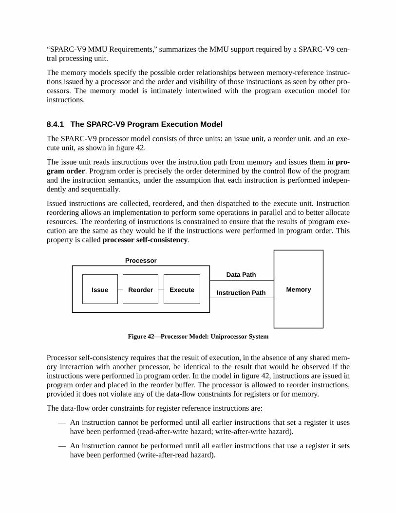
en-
struc-er pro-l for
n exe-
ramdepen-
ructionlocatem exe-. This
d mem-if theed intions,
uses
sets
“SPARC-V9 MMU Requirements,” summarizes the MMU support required by a SPARC-V9 ctral processing unit.
The memory models specify the possible order relationships between memory-reference intions issued by a processor and the order and visibility of those instructions as seen by othcessors. The memory model is intimately intertwined with the program execution modeinstructions.
8.4.1 The SPARC-V9 Program Execution Model
The SPARC-V9 processor model consists of three units: an issue unit, a reorder unit, and acute unit, as shown in figure 42.
The issue unit reads instructions over the instruction path from memory and issues them inpro-gram order. Program order is precisely the order determined by the control flow of the progand the instruction semantics, under the assumption that each instruction is performed indently and sequentially.
Issued instructions are collected, reordered, and then dispatched to the execute unit. Instreordering allows an implementation to perform some operations in parallel and to better alresources. The reordering of instructions is constrained to ensure that the results of progracution are the same as they would be if the instructions were performed in program orderproperty is calledprocessor self-consistency.
Figure 42—Processor Model: Uniprocessor System
Processor self-consistency requires that the result of execution, in the absence of any shareory interaction with another processor, be identical to the result that would be observedinstructions were performed in program order. In the model in figure 42, instructions are issuprogram order and placed in the reorder buffer. The processor is allowed to reorder instrucprovided it does not violate any of the data-flow constraints for registers or for memory.
The data-flow order constraints for register reference instructions are:
— An instruction cannot be performed until all earlier instructions that set a register ithave been performed (read-after-write hazard; write-after-write hazard).
— An instruction cannot be performed until all earlier instructions that use a register ithave been performed (write-after-read hazard).
Processor
Memory
Data Path
Instruction PathIssue Reorder Execute
nam-new
rence
untilrite-
per-have
y pro-valuee storeifferentwritewritery.
d byEM-
ordergram.
g twogs aresistentrequire
uctiontributeds are
ssor exe-by pro-ated by
ng
An implementation can avoid blocking instruction execution in the second case by using a reing mechanism which provides the old value of the register to earlier instructions and thevalue to later uses.
The data-flow order constraints for memory-reference instructions are those for register refeinstructions, plus the following additional constraints:
(1) A memory-reference instruction that sets (stores to) a location cannot be performedall previous instructions that use (load from) the location have been performed (wafter-read hazard).
(2) A memory-reference instruction that uses (loads) the value at a location cannot beformed until all earlier memory-reference instructions that set (store to) the locationbeen performed (read-after-write hazard).
As with the case for registers, implementations can avoid blocking instructions in case (2) bviding an additional mechanism, in this case, a write buffer which guarantees that thereturned by a load is that which would be returned by the most recent store, even though thhas not completed. As a result, the value associated with an address may appear to be dwhen observed from a processor that has written the location and is holding the value in itsbuffer than it would be when observed from a processor that references memory (or its ownbuffer). Moreover, the load that was satisfied by the write buffer never appears at the memo
Memory-barrier instructions (MEMBAR and STBAR) and the active memory model specifiePSTATE.MM also constrain the issue of memory-reference instructions. See 8.4.3, “The MBAR Instruction,” and 8.4.4, “Memory Models,” for a detailed description.
The constraints on instruction execution assert a partial ordering on the instructions in the rebuffer. Every one of the several possible orderings is a legal execution ordering for the proSee Appendix D, “Formal Specification of the Memory Models,” for more information.
8.4.2 The Processor/Memory Interface Model
Each processor in a multiprocessor system is modelled as shown in figure 43; that is, havinindependent paths to memory: one for instructions and one for data. Caches and mappinconsidered to be part of the memory. Data caches are maintained by hardware to be con(coherent). Instruction caches need not be kept consistent with data caches and, therefore,explicit program action to ensure consistency when a program modifies an executing instrstream. Memory is shared in terms of address space, but may be inhomogeneous and disin an implementation. Mapping and caches are ignored in the model, since their functiontransparent to the memory model.1
In real systems addresses may have attributes that the processor must respect. The procecutes loads, stores, and atomic load-stores in whatever order it chooses, as constrainedgram order and the current memory model. The ASI address-couples it generates are transl
1. The model described here is only a model. Implementations of SPARC-V9 systems are unsonstrained so loas their observable behaviors match those of the model.
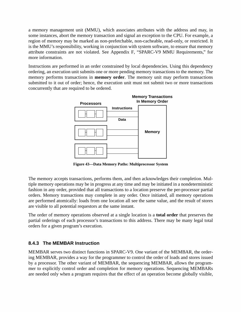
ay, inmple, acted. Itory
” for
dencyy. Thestions
. Mul-inisticpartialtionsstores
al total
er-suedam-
ARsisible,
a memory management unit (MMU), which associates attributes with the address and msome instances, abort the memory transaction and signal an exception to the CPU. For exaregion of memory may be marked as non-prefetchable, non-cacheable, read-only, or restriis the MMU’s responsibility, working in conjunction with system software, to ensure that memattribute constraints are not violated. See Appendix F, “SPARC-V9 MMU Requirements,more information.
Instructions are performed in an order constrained by local dependencies. Using this depenordering, an execution unit submits one or more pending memory transactions to the memormemory performs transactions inmemory order. The memory unit may perform transactionsubmitted to it out of order; hence, the execution unit must not submit two or more transacconcurrently that are required to be ordered.
Figure 43—Data Memory Paths: Multiprocessor System
The memory accepts transactions, performs them, and then acknowledges their completiontiple memory operations may be in progress at any time and may be initiated in a nondetermfashion in any order, provided that all transactions to a location preserve the per-processororders. Memory transactions may complete in any order. Once initiated, all memory operaare performed atomically: loads from one location all see the same value, and the result ofare visible to all potential requestors at the same instant.
The order of memory operations observed at a single location is atotal order that preserves thepartial orderings of each processor’s transactions to this address. There may be many legorders for a given program’s execution.
8.4.3 The MEMBAR Instruction
MEMBAR serves two distinct functions in SPARC-V9. One variant of the MEMBAR, the ording MEMBAR, provides a way for the programmer to control the order of loads and stores isby a processor. The other variant of MEMBAR, the sequencing MEMBAR, allows the progrmer to explicitly control order and completion for memory operations. Sequencing MEMBare needed only when a program requires that the effect of an operation become globally v
Processors
Memory TransactionsIn Memory Order
Memory
Instructions
Data
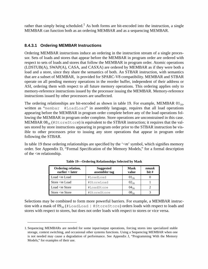
le
ces-d withtionsa
anticsR
ess orly torence
01nss fol-case.al-e vis-order
tion
truc-d
blenery
rather than simply being scheduled.1 As both forms are bit-encoded into the instruction, a singMEMBAR can function both as an ordering MEMBAR and as a sequencing MEMBAR.
8.4.3.1 Ordering MEMBAR Instructions
Ordering MEMBAR instructions induce an ordering in the instruction stream of a single prosor. Sets of loads and stores that appear before the MEMBAR in program order are ordererespect to sets of loads and stores that follow the MEMBAR in program order. Atomic opera(LDSTUB(A), SWAP(A), CASA, and CASXA) are ordered by MEMBAR as if they were bothload and a store, since they share the semantics of both. An STBAR instruction, with semthat are a subset of MEMBAR, is provided for SPARC-V8 compatibility. MEMBAR and STBAoperate on all pending memory operations in the reorder buffer, independent of their addrASI, ordering them with respect to all future memory operations. This ordering applies onmemory-reference instructions issued by the processor issuing the MEMBAR. Memory-refeinstructions issued by other processors are unaffected.
The ordering relationships are bit-encoded as shown in table 19. For example, MEMBAR16,written as “membar #LoadLoad ” in assembly language, requires that all load operatioappearing before the MEMBAR in program order complete before any of the load operationlowing the MEMBAR in program order complete. Store operations are unconstrained in thisMEMBAR 0816 (#StoreStor e) is equivalent to the STBAR instruction; it requires that the vues stored by store instructions appearing in program order prior to the STBAR instruction bible to other processors prior to issuing any store operations that appear in programfollowing the STBAR.
In table 19 these ordering relationships are specified by the ‘<m’ symbol, which signifies memoryorder. See Appendix D, “Formal Specification of the Memory Models,” for a formal descripof the <m relationship.
Selections may be combined to form more powerful barriers. For example, a MEMBAR instion with a mask of 0916 (#LoadLoad | #StoreStore ) orders loads with respect to loads anstores with respect to stores, but does not order loads with respect to stores or vice versa.
1. Sequencing MEMBARs are needed for some input/output operations, forcing stores into specialized stastorage, context switching, and occasional other systems functions. Using a Sequencing MEMBAR when ois not needed may cause a degradation of performance. See Appendix J, “Programming With the MemoModels,” for examples of their use.
Table 19—Ordering Relationships Selected by Mask
Ordering relation,earlier < later
Suggestedassembler tag
Maskvalue
nmaskbit #
Load <m Load #LoadLoad 0116 0
Store <m Load #StoreLoad 0216 1
Load <m Store #LoadStore 0416 2
Store <m Store #StoreStore 0816 3

tro-eding a
areppli-
ideheaytoisters
ncingthe
BARction
uponnsis-fol-
An ordering MEMBAR instruction does not guarantee any completion property; it only induces an ordering constraint. For example, a program should not assume that a store precMEMBAR instruction has completed following execution of the MEMBAR.
8.4.3.2 Sequencing MEMBAR Instructions
A sequencing MEMBAR exerts explicit control over the completion of operations. Therethree sequencing MEMBAR options, each with a different degree of control and a different acation.
Lookaside Barrier:Ensures that loads following this MEMBAR are from memory and not from a lookasinto a write buffer.Lookaside Barrier requires that pending stores issued prior to tMEMBAR be completed before any load from that address following the MEMBAR mbe issued. ALookaside Barrier MEMBAR may be needed to provide lock fairness andsupport some plausible I/O location semantics. See the example in J.14.1, “I/O RegWith Side Effects.”
Memory Issue Barrier:Ensures that all memory operations appearing in program order before the sequeMEMBAR complete before any any new memory operation may be initiated. Seeexample in J.14.2, “The Control and Status Register (CSR).”
Synchronization Barrier:Ensures that all instructions (memory reference and others) preceding the MEMcomplete and the effects of any fault or error have become visible before any instrufollowing the MEMBAR in program order is initiated. ASynchronization BarrierMEMBAR fully synchronizes the processor that issues it.
Table 20 shows the encoding of these functions in the MEMBAR instruction.
8.4.4 Memory Models
The SPARC-V9 memory models are defined below in terms of order constraints placedmemory-reference instruction execution, in addition to the minimal set required for self-cotency. These order constraints take the form of MEMBAR operations implicitly performedlowing some memory-reference instructions.
Table 20—Sequencing Barrier Selected by Mask
Sequencingfunction
Assembler tag Maskvalue
cmaskbit#
Lookaside Barrier #Lookaside 1016 0
Memory Issue Barrier #MemIssue 2016 1
Synchronization Barrier #Sync 4016 2
hoselicitly
o-odel.
AR
ruc-
ro-l.
e of
8
of
8.4.4.1 Relaxed Memory Order (RMO)
Relaxed Memory Order places no ordering constraints on memory references beyond trequired for processor self-consistency. When ordering is required, it must be provided expin the programs using MEMBAR instructions.
8.4.4.2 Partial Store Order (PSO)
Partial Store Order may be provided for compatibility with existing SPARC-V8 programs. Prgrams that execute correctly in the RMO memory model will execute correctly in the PSO m
The rules for PSO are:
— Loads are blocking and ordered with respect to earlier loads.
— Atomic load-stores are ordered with respect to loads.
Thus, PSO ensures that:
— Each load and atomic load-store instruction behaves as if it were followed by a MEMBwith a mask value of 0516.
— Explicit MEMBAR instructions are required to order store and atomic load-store insttions with respect to each other.
8.4.4.3 Total Store Order (TSO)
Total Store Order must be provided for compatibility with existing SPARC-V8 programs. Pgrams that execute correctly in either RMO or PSO will execute correctly in the TSO mode
The rules for TSO are:
— Loads are blocking and ordered with respect to earlier loads.
— Stores are ordered with respect to stores.
— Atomic load-stores are ordered with respect to loads and stores.
Thus, TSO ensures that:
— Each load instruction behaves as if it were followed by a MEMBAR with a mask valu0516.
— Each store instruction behaves as if it were followed by a MEMBAR with a mask of 016.
— Each atomic load-store behaves as if it were followed by a MEMBAR with a mask0D16.
.1.4,
to be
es of
tibil-
d and.
ual-utual
odels.storeem-
men-rim-tion is20).
er to ain a
. Then access
8.4.5 Mode Control
The memory model is specified by the two-bit state in PSTATE.MM, described in 5.2“PSTATE_mem_model (MM).”
Writing a new value into PSTATE.MM causes subsequent memory reference instructionsperformed with the order constraints of the specified memory model.
SPARC-V9 processors need not provide all three memory models; undefined valuPSTATE.MM have implementation-dependent effects.
IMPL. DEP. #119: The effect of writing an unimplemented memory mode designation into PSTATE.MM isimplementation-dependent.
Implementation Note:All SPARC-V9 implementations must provide TSO or a stronger model to maintain SPARC-V8 compaity. An implementation may provide PSO, RMO, or neither.
Except when a trap enters RED_state, PSTATE.MM is left unchanged when a trap is enterethe old value is stacked. When entering RED_state, the value of PSTATE.MM is set to TSO
8.4.6 Hardware Primitives for Mutual Exclusion
In addition to providing memory-ordering primitives that allow programmers to construct mutexclusion mechanisms in software, SPARC-V9 provides three hardware primitives for mexclusion:
— Compare and Swap (CASA, CASXA)
— Load Store Unsigned Byte (LDSTUB, LDSTUBA)
— Swap (SWAP, SWAPA)
Each of these instructions has the semantics of both a load and a store in all three memory mThey are allatomic, in the sense that no other store can be performed between the load andelements of the instruction. All of the hardware mutual exclusion operations conform to the mory models and may require barrier instructions to ensure proper data visibility.
When the hardware mutual-exclusion primitives address I/O locations, the results are impletation-dependent (impl. dep. #123). In addition, the atomicity of hardware mutual-exclusion pitives is guaranteed only for processor memory references and not when the memory locasimultaneously being addressed by an I/O device such as a channel or DMA (impl. dep. #1
8.4.6.1 Compare and Swap (CASA, CASXA)
Compare-and-swap is an atomic operation which compares a value in a processor registvalue in memory, and, if and only if they are equal, swaps the value in memory with the valuesecond processor register. Both 32-bit (CASA) and 64-bit (CASXA) operations are providedcompare-and-swap operation is atomic in the sense that once begun, no other processor ca
s also
prim-finiteto con-
ming
ory.g pro-
has aa wait-
e con-a pro-by acachepecial
refer-ing thee pro-ultiplerformeded to
rget ofs, and
ts as astore
the memory location specified until the compare has completed and the swap (if any) hacompleted and is potentially visible to all other processors in the system.
Compare-and-swap is substantially more powerful than the other hardware synchronizationitives. It has an infinite consensus number; that is, it can resolve, in a wait-free fashion, an innumber of contending processes. Because of this property, compare-and-swap can be usedstruct wait-free algorithms that do not require the use of locks. See Appendix J, “ProgramWith the Memory Models,” for examples.
8.4.6.2 Swap (SWAP)
SWAP atomically exchanges the lower 32 bits in a processor register with a word in memSwap has a consensus number of two; that is, it cannot resolve more than two contendincesses in a wait-free fashion.
8.4.6.3 Load Store Unsigned Byte (LDSTUB)
LDSTUB loads a byte value from memory to a register and writes the value FF16 into theaddressed byte atomically. LDSTUB is the classic test-and-set instruction. Like SWAP, itconsensus number of two and so cannot resolve more than two contending processes infree fashion.
8.4.7 Synchronizing Instruction and Data Memory
The SPARC-V9 memory models do not require that instruction and data memory images bsistent at all times. The instruction and data memory images may become inconsistent ifgram writes into the instruction stream. As a result, whenever instructions are modifiedprogram in a context where the data (that is, the instructions) in the memory and the datahierarchy may be inconsistent with instructions in the instruction cache hierarchy, some sprogrammatic action must be taken.
The FLUSH instruction will ensure consistency between the instruction stream and the dataences across any local caches for a particular doubleword value in the processor executFLUSH. It will ensure eventual consistency across all caches in a multiprocessor system. Thgrammer must be careful to ensure that the modification sequence is robust under mupdates and concurrent execution. Since, in the general case, loads and stores may be peout of order, appropriate MEMBAR and FLUSH instructions must be interspersed as needcontrol the order in which the instruction data is mutated.
The FLUSH instruction ensures that subsequent instruction fetches from the doubleword tathe FLUSH by the processor executing the FLUSH appear to execute after any loads, storeatomic load-stores issued by the processor to that address prior to the FLUSH. FLUSH acbarrier for instruction fetches in the processor that executes it and has the properties of awith respect to MEMBAR operations.

iately
proto-
dationinstruc-
USH,e line.
H maytine forries ofh the
o sub-
that
‘—’rotersg theset.
ed in
te the
FLUSH has no latency on the issuing processor; the modified instruction stream is immedavailable.1
IMPL. DEP. #122: The latency between the execution of FLUSH on one processor and the point at whichthe modified instructions have replaced outdated instructions in a multiprocessor is implementation-depen-dent.
If all caches in a system (uniprocessor or multiprocessor) have a unified cache consistencycol, FLUSH does nothing.
Use of FLUSH in a multiprocessor environment may cause unexpected performance degrain some systems, because every processor that may have a copy of the modified data in itstion cache must invalidate that data. In the worst case naive system,all processors must invalidatethe data. The performance problem is compounded by the doubleword granularity of the FLwhich must be observed even when the actual invalidation unit is larger, for example, a cach
Programming Note:Because FLUSH is designed to act on a doubleword, and because, on some implementations, FLUStrap to system software, it is recommended that system software provide a user-callable service rouflushing arbitrarily sized regions of memory. On some implementations, this routine would issue a seFLUSH instructions; on others, it might issue a single trap to system software that would then flusentire region.
A Instruction Definitions
A.1 Overview
This appendix describes each SPARC-V9 instruction. Related instructions are grouped intsections. Each subsection consists of these parts:
(1) A table of the opcodes defined in the subsection with the values of the field(s)uniquely identify the instruction(s).
(2) An illustration of the applicable instruction format(s). In these illustrations, a dashindicates that the field isreservedfor future versions of the architecture and shall be zein any instance of the instruction. If a conforming SPARC-V9 implementation encounnonzero values in these fields, its behavior is undefined. See Appendix I, “ExtendinSPARC-V9 Architecture,” for information about extending the SPARC-V9 instruction
(3) A list of the suggested assembly language syntax; the syntax notation is describAppendix G, “Suggested Assembly Language Syntax.”
(4) A description of the features, restrictions, and exception-causing conditions.
(5) A list of the exceptions that can occur as a consequence of attempting to execuinstruction(s). Exceptions due to aninstruction_access_error, instruction_access_exception,
1. SPARC-V8 specified a five-instruction latency. Invalidation of instructions in execution in the instructioncache is likely to force an instruction-cache fault.
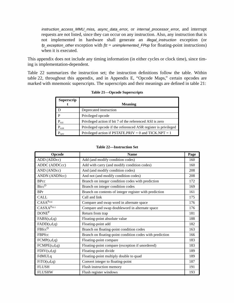
hat is
tim-
ithins areble 21:
instruction_access_MMU_miss, async_data_error, or internal_processor_error, and interruptrequests are not listed, since they can occur on any instruction. Also, any instruction tnot implemented in hardware shall generate anillegal_instruction exception (orfp_exception_other exception withftt = unimplemented_FPop for floating-point instructions)when it is executed.
This appendix does not include any timing information (in either cycles or clock time), sinceing is implementation-dependent.
Table 22 summarizes the instruction set; the instruction definitions follow the table. Wtable 22, throughout this appendix, and in Appendix E, “Opcode Maps,” certain opcodemarked with mnemonic superscripts. The superscripts and their meanings are defined in ta
Table 21—Opcode Superscripts
Superscript Meaning
D Deprecated instruction
P Privileged opcode
PASI Privileged action if bit 7 of the referenced ASI is zero
PASR Privileged opcode if the referenced ASR register is privileged
PNPT Privileged action if PSTATE.PRIV = 0 and TICK.NPT = 1
Table 22—Instruction Set
Opcode Name PageADD (ADDcc) Add (and modify condition codes) 160
ADDC (ADDCcc) Add with carry (and modify condition codes) 160
AND (ANDcc) And (and modify condition codes) 208
ANDN (ANDNcc) And not (and modify condition codes) 208
BPcc Branch on integer condition codes with prediction 172
BiccD Branch on integer condition codes 169
BPr Branch on contents of integer register with prediction 161
CALL Call and link 175
CASAPASI Compare and swap word in alternate space 176
CASXAPAS I Compare and swap doubleword in alternate space 176
DONEP Return from trap 181
FABS(s,d,q) Floating-point absolute value 188
FADD(s,d,q) Floating-point add 182
FBfccD Branch on floating-point condition codes 163
FBPfcc Branch on floating-point condition codes with prediction 166
FCMP(s,d,q) Floating-point compare 183
FCMPE(s,d,q) Floating-point compare (exception if unordered) 183
FDIV(s,d,q) Floating-point divide 189
FdMULq Floating-point multiply double to quad 189
FiTO(s,d,q) Convert integer to floating-point 187
FLUSH Flush instruction memory 191
FLUSHW Flush register windows 193
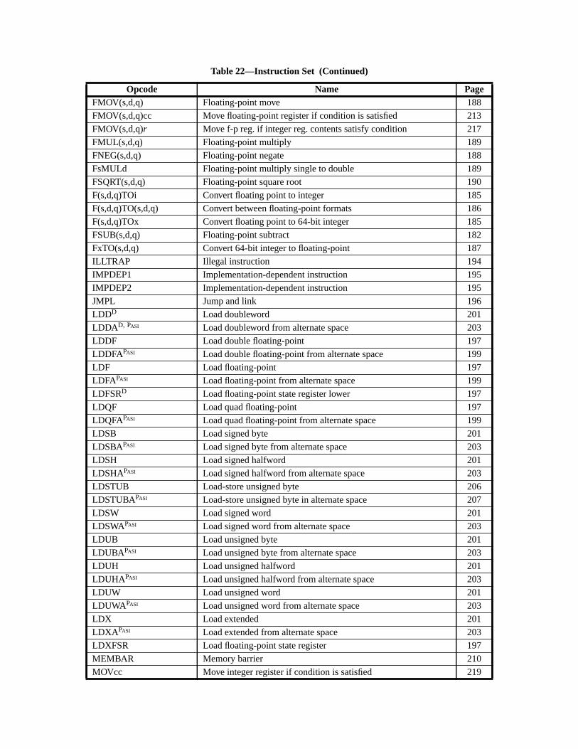
FMOV(s,d,q) Floating-point move 188
FMOV(s,d,q)cc Move floating-point register if condition is satisfied 213
FMOV(s,d,q)r Move f-p reg. if integer reg. contents satisfy condition 217
FMUL(s,d,q) Floating-point multiply 189
FNEG(s,d,q) Floating-point negate 188
FsMULd Floating-point multiply single to double 189
FSQRT(s,d,q) Floating-point square root 190
F(s,d,q)TOi Convert floating point to integer 185
F(s,d,q)TO(s,d,q) Convert between floating-point formats 186
F(s,d,q)TOx Convert floating point to 64-bit integer 185
FSUB(s,d,q) Floating-point subtract 182
FxTO(s,d,q) Convert 64-bit integer to floating-point 187
ILLTRAP Illegal instruction 194
IMPDEP1 Implementation-dependent instruction 195
IMPDEP2 Implementation-dependent instruction 195
JMPL Jump and link 196
LDDD Load doubleword 201
LDDAD, PASI Load doubleword from alternate space 203
LDDF Load double floating-point 197
LDDFAPASI Load double floating-point from alternate space 199
LDF Load floating-point 197
LDFAPASI Load floating-point from alternate space 199
LDFSRD Load floating-point state register lower 197
LDQF Load quad floating-point 197
LDQFAPASI Load quad floating-point from alternate space 199
LDSB Load signed byte 201
LDSBAPASI Load signed byte from alternate space 203
LDSH Load signed halfword 201
LDSHAPASI Load signed halfword from alternate space 203
LDSTUB Load-store unsigned byte 206
LDSTUBAPASI Load-store unsigned byte in alternate space 207
LDSW Load signed word 201
LDSWAPASI Load signed word from alternate space 203
LDUB Load unsigned byte 201
LDUBAPASI Load unsigned byte from alternate space 203
LDUH Load unsigned halfword 201
LDUHAPASI Load unsigned halfword from alternate space 203
LDUW Load unsigned word 201
LDUWAPASI Load unsigned word from alternate space 203
LDX Load extended 201
LDXA PASI Load extended from alternate space 203
LDXFSR Load floating-point state register 197
MEMBAR Memory barrier 210
MOVcc Move integer register if condition is satisfied 219
Table 22—Instruction Set (Continued)
Opcode Name Page
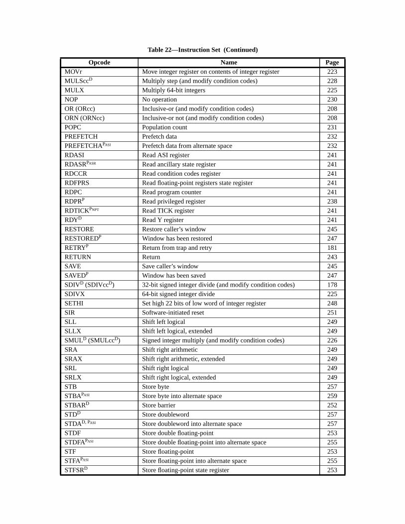
MOVr Move integer register on contents of integer register 223
MULSccD Multiply step (and modify condition codes) 228
MULX Multiply 64-bit integers 225
NOP No operation 230
OR (ORcc) Inclusive-or (and modify condition codes) 208
ORN (ORNcc) Inclusive-or not (and modify condition codes) 208
POPC Population count 231
PREFETCH Prefetch data 232
PREFETCHAPASI Prefetch data from alternate space 232
RDASI Read ASI register 241
RDASRPASR Read ancillary state register 241
RDCCR Read condition codes register 241
RDFPRS Read floating-point registers state register 241
RDPC Read program counter 241
RDPRP Read privileged register 238
RDTICKPNPT Read TICK register 241
RDYD Read Y register 241
RESTORE Restore caller’s window 245
RESTOREDP Window has been restored 247
RETRYP Return from trap and retry 181
RETURN Return 243
SAVE Save caller’s window 245
SAVEDP Window has been saved 247
SDIVD (SDIVccD) 32-bit signed integer divide (and modify condition codes) 178
SDIVX 64-bit signed integer divide 225
SETHI Set high 22 bits of low word of integer register 248
SIR Software-initiated reset 251
SLL Shift left logical 249
SLLX Shift left logical, extended 249
SMULD (SMULccD) Signed integer multiply (and modify condition codes) 226
SRA Shift right arithmetic 249
SRAX Shift right arithmetic, extended 249
SRL Shift right logical 249
SRLX Shift right logical, extended 249
STB Store byte 257
STBAPASI Store byte into alternate space 259
STBARD Store barrier 252
STDD Store doubleword 257
STDAD, PASI Store doubleword into alternate space 257
STDF Store double floating-point 253
STDFAPASI Store double floating-point into alternate space 255
STF Store floating-point 253
STFAPASI Store floating-point into alternate space 255
STFSRD Store floating-point state register 253
Table 22—Instruction Set (Continued)
Opcode Name Page
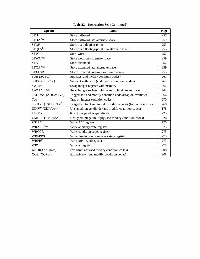
STH Store halfword 257
STHAPASI Store halfword into alternate space 259
STQF Store quad floating-point 253
STQFAPASI Store quad floating-point into alternate space 255
STW Store word 257
STWAPASI Store word into alternate space 259
STX Store extended 257
STXAPASI Store extended into alternate space 259
STXFSR Store extended floating-point state register 253
SUB (SUBcc) Subtract (and modify condition codes) 261
SUBC (SUBCcc) Subtract with carry (and modify condition codes) 261
SWAPD Swap integer register with memory 262
SWAPAD, PASI Swap integer register with memory in alternate space 264
TADDcc (TADDccTVD) Tagged add and modify condition codes (trap on overflow) 266
Tcc Trap on integer condition codes 270
TSUBcc (TSUBccTVD) Tagged subtract and modify condition codes (trap on overflow) 268
UDIVD (UDIVccD) Unsigned integer divide (and modify condition codes) 178
UDIVX 64-bit unsigned integer divide 225
UMULD (UMULccD) Unsigned integer multiply (and modify condition codes) 226
WRASI Write ASI register 275
WRASRPASR Write ancillary state register 275
WRCCR Write condition codes register 275
WRFPRS Write floating-point registers state register 275
WRPRP Write privileged register 273
WRYD Write Y register 275
XNOR (XNORcc) Exclusive-nor (and modify condition codes) 208
XOR (XORcc) Exclusive-or (and modify condition codes) 208
Table 22—Instruction Set (Continued)
Opcode Name Page
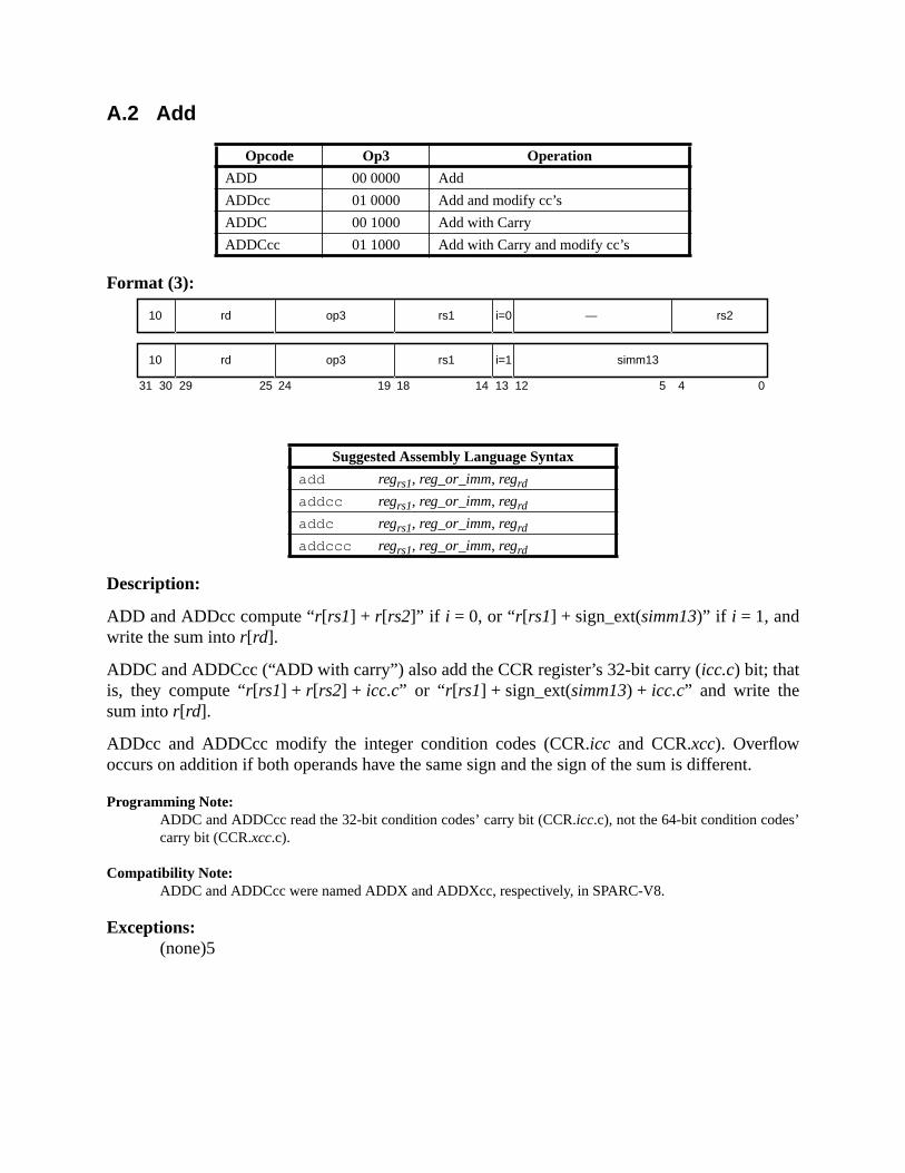
.
A.2 Add
Format (3):
Description:
ADD and ADDcc compute “r[rs1] + r[rs2]” if i = 0, or “r[rs1] + sign_ext(simm13)” if i = 1, andwrite the sum intor[rd].
ADDC and ADDCcc (“ADD with carry”) also add the CCR register’s 32-bit carry (icc.c) bit; thatis, they compute “r[rs1] + r[rs2] + icc.c” or “ r[rs1] + sign_ext(simm13) + icc.c” and write thesum intor[rd].
ADDcc and ADDCcc modify the integer condition codes (CCR.icc and CCR.xcc). Overflowoccurs on addition if both operands have the same sign and the sign of the sum is different
Programming Note:ADDC and ADDCcc read the 32-bit condition codes’ carry bit (CCR.icc.c), not the 64-bit condition codes’carry bit (CCR.xcc.c).
Compatibility Note:ADDC and ADDCcc were named ADDX and ADDXcc, respectively, in SPARC-V8.
Exceptions:(none)5
Opcode Op3 Operation
ADD 00 0000 Add
ADDcc 01 0000 Add and modify cc’s
ADDC 00 1000 Add with Carry
ADDCcc 01 1000 Add with Carry and modify cc’s
Suggested Assembly Language Syntax
add regrs1, reg_or_imm, regrd
addcc regrs1, reg_or_imm, regrd
addc regrs1, reg_or_imm, regrd
addccc regrs1, reg_or_imm, regrd
31 24 02530 29 19 18
rd10 op3 —
14 13 12 5 4
rs1 rs2i=0
rd10 op3 rs1 simm13i=1
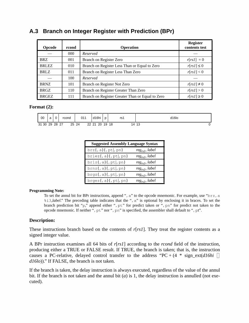
e
a
tion
annul-
A.3 Branch on Integer Register with Prediction (BPr)
Format (2):
Programming Note:To set the annul bit for BPr instructions, append “,a ” to the opcode mnemonic. For example, use “brz,a%i3 ,label.” The preceding table indicates that the “,a ” is optional by enclosing it in braces. To set thbranch prediction bit “p,” append either “,pt ” for predict taken or “,pn ” for predict not taken to theopcode mnemonic. If neither “,pt ” nor “,pn ” is specified, the assembler shall default to “,p t”.
Description:
These instructions branch based on the contents ofr[rs1]. They treat the register contents assigned integer value.
A BPr instruction examines all 64 bits ofr[rs1] according to thercond field of the instruction,producing either a TRUE or FALSE result. If TRUE, the branch is taken; that is, the instruccauses a PC-relative, delayed control transfer to the address “PC + (4 * sign_ext(d16hid16lo)).” If FALSE, the branch is not taken.
If the branch is taken, the delay instruction is always executed, regardless of the value of thebit. If the branch is not taken and the annul bit (a) is 1, the delay instruction is annulled (not executed).
Opcode rcond OperationRegister
contents test
— 000 Reserved —
BRZ 001 Branch on Register Zero r[rs1] = 0
BRLEZ 010 Branch on Register Less Than or Equal to Zero r[rs1] ≤ 0
BRLZ 011 Branch on Register Less Than Zero r[rs1] < 0
— 100 Reserved —
BRNZ 101 Branch on Register Not Zero r[rs1] ≠ 0
BRGZ 110 Branch on Register Greater Than Zero r[rs1] > 0
BRGEZ 111 Branch on Register Greater Than or Equal to Zero r[rs1] ≥ 0
Suggested Assembly Language Syntax
brz { ,a }{ ,pt |,pn } regrs1, label
brlez { ,a }{ ,pt |,pn } regrs1, label
brlz { ,a }{ ,pt |,pn } regrs1, label
brnz { ,a }{ ,pt |,pn } regrs1, label
brgz { ,a }{ ,pt |,pn } regrs1, label
brgez { ,a }{ ,pt |,pn } regrs1, label
31 141924 18 13 027 2530 29 28 22 21 20
00 a 0 rcond 011 d16hi p rs1 d16lo

to bet the
her in
t, the
The predict bit (p) is used to give the hardware a hint about whether the branch is expectedtaken. A 1 in thep bit indicates that the branch is expected to be taken; a 0 indicates thabranch is expected not to be taken.
Annulment, delay instructions, prediction, and delayed control transfers are described furtChapter 6, “Instructions.”
Implementation Note:If this instruction is implemented by tagging each register value with an N (negative) bit and Z (zero) bifollowing table can be used to determine ifrcond is TRUE:
Exceptions:illegal_instruction (if rcond= 0002 or 1002)
Branch Test
BRNZ not Z
BRZ Z
BRGEZ not N
BRLZ N
BRLEZ N or Z
BRGZ not (N or Z)
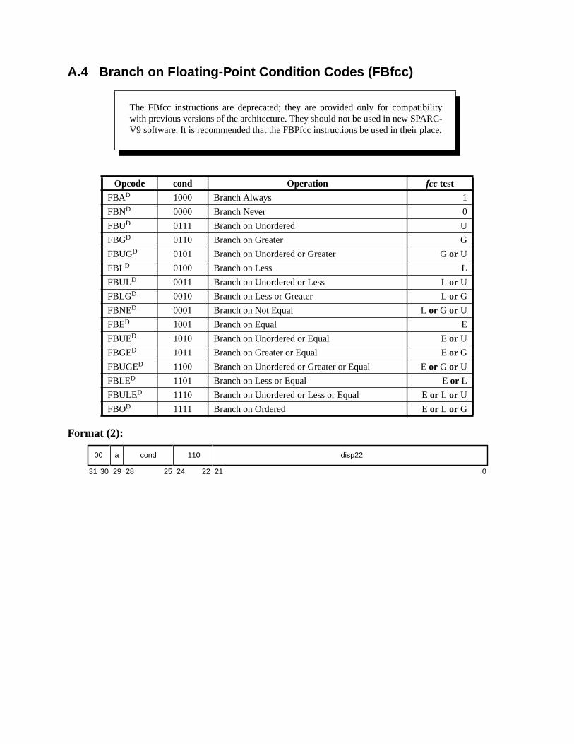
A.4 Branch on Floating-Point Condition Codes (FBfcc)
Format (2):
Opcode cond Operation fcc test
FBAD 1000 Branch Always 1
FBND 0000 Branch Never 0
FBUD 0111 Branch on Unordered U
FBGD 0110 Branch on Greater G
FBUGD 0101 Branch on Unordered or Greater Gor U
FBLD 0100 Branch on Less L
FBULD 0011 Branch on Unordered or Less Lor U
FBLGD 0010 Branch on Less or Greater Lor G
FBNED 0001 Branch on Not Equal Lor G or U
FBED 1001 Branch on Equal E
FBUED 1010 Branch on Unordered or Equal Eor U
FBGED 1011 Branch on Greater or Equal Eor G
FBUGED 1100 Branch on Unordered or Greater or Equal Eor G or U
FBLED 1101 Branch on Less or Equal Eor L
FBULED 1110 Branch on Unordered or Less or Equal Eor L or U
FBOD 1111 Branch on Ordered Eor L or G
The FBfcc instructions are deprecated; they are provided only for compatibilitywith previous versions of the architecture. They should not be used in new SPARC-V9 software. It is recommended that the FBPfcc instructions be used in their place.
31 24 02530 29 28 22 21
cond00 a 110 disp22
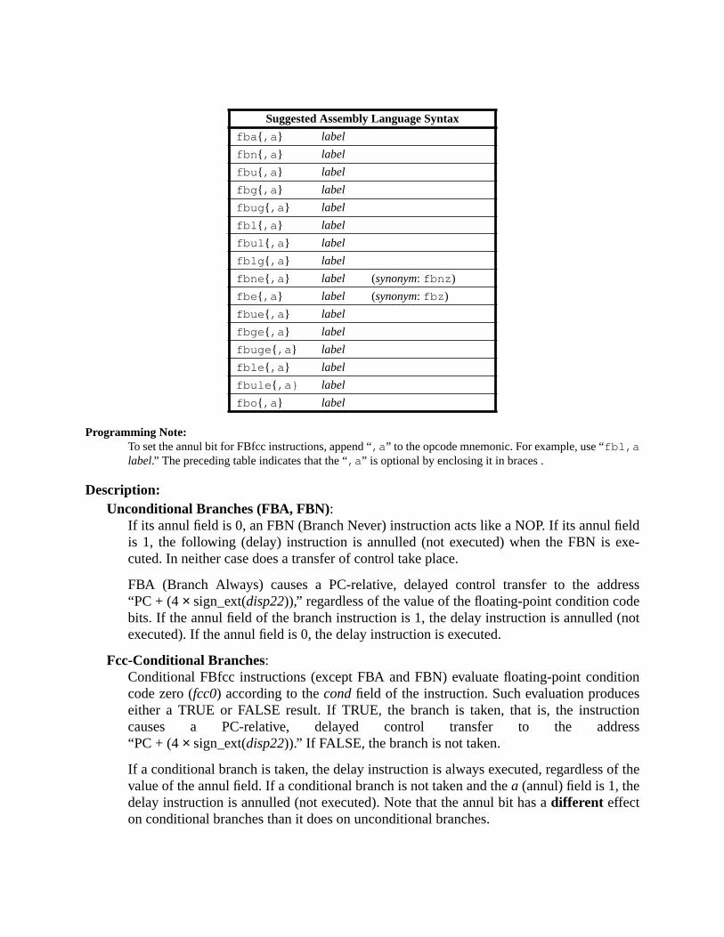
eldxe-
ressde(not
ions
tionress
of the
Programming Note:To set the annul bit for FBfcc instructions, append “,a ” to the opcode mnemonic. For example, use “fbl,alabel.” The preceding table indicates that the “,a ” is optional by enclosing it in braces .
Description:Unconditional Branches (FBA, FBN):
If its annul field is 0, an FBN (Branch Never) instruction acts like a NOP. If its annul fiis 1, the following (delay) instruction is annulled (not executed) when the FBN is ecuted. In neither case does a transfer of control take place.
FBA (Branch Always) causes a PC-relative, delayed control transfer to the add“PC + (4× sign_ext(disp22)),” regardless of the value of the floating-point condition cobits. If the annul field of the branch instruction is 1, the delay instruction is annulledexecuted). If the annul field is 0, the delay instruction is executed.
Fcc-Conditional Branches:Conditional FBfcc instructions (except FBA and FBN) evaluate floating-point conditcode zero (fcc0) according to thecondfield of the instruction. Such evaluation produceeither a TRUE or FALSE result. If TRUE, the branch is taken, that is, the instruccauses a PC-relative, delayed control transfer to the add“PC + (4× sign_ext(disp22)).” If FALSE, the branch is not taken.
If a conditional branch is taken, the delay instruction is always executed, regardlessvalue of the annul field. If a conditional branch is not taken and thea (annul) field is 1, thedelay instruction is annulled (not executed). Note that the annul bit has adifferent effecton conditional branches than it does on unconditional branches.
Suggested Assembly Language Syntax
fba { ,a } label
fbn { ,a } label
fbu { ,a } label
fbg { ,a } label
fbug { ,a } label
fbl { ,a } label
fbul { ,a } label
fblg { ,a } label
fbne { ,a } label (synonym: fbnz )
fbe { ,a } label (synonym: fbz )
fbue { ,a } label
fbge { ,a } label
fbuge { ,a } label
fble { ,a } label
fbule { ,a} label
fbo { ,a } label

er in
ration
not
Annulment, delay instructions, and delayed control transfers are described furthChapter 6, “Instructions.”
Compatibility Note:Unlike SPARC-V8, SPARC-V9 does not require an instruction between a floating-point compare opeand a floating-point branch (FBfcc, FBPfcc).
If FPRS.FEF = 0 or PSTATE.PEF = 0, or if an FPU is not present, the FBfcc instruction isexecuted and instead, generates anfp_disabled exception.
Exceptions:fp_disabled

A.5 Branch on Floating-Point Condition Codes with Prediction(FBPfcc)
Format (2):
Opcode cond Operation fcc test
FBPA 1000 Branch Always 1
FBPN 0000 Branch Never 0
FBPU 0111 Branch on Unordered U
FBPG 0110 Branch on Greater G
FBPUG 0101 Branch on Unordered or Greater Gor U
FBPL 0100 Branch on Less L
FBPUL 0011 Branch on Unordered or Less Lor U
FBPLG 0010 Branch on Less or Greater Lor G
FBPNE 0001 Branch on Not Equal Lor G or U
FBPE 1001 Branch on Equal E
FBPUE 1010 Branch on Unordered or Equal Eor U
FBPGE 1011 Branch on Greater or Equal Eor G
FBPUGE 1100 Branch on Unordered or Greater or Equal Eor G or U
FBPLE 1101 Branch on Less or Equal Eor L
FBPULE 1110 Branch on Unordered or Less or Equal Eor L or U
FBPO 1111 Branch on Ordered Eor L or G
cc1 cc0Condition
code
00 fcc0
01 fcc1
10 fcc2
11 fcc3
31 1924 18 02530 29 28 22 21 20
00 a cond 101 cc1 p disp19cc0

e
ionn is
no
ela-
f the
oat-
heto the
Programming Note:To set the annul bit for FBPfcc instructions, append “,a ” to the opcode mnemonic. For example, us“ fbl,a %fcc3,label .” The preceding table indicates that the “,a ” is optional by enclosing it in braces.To set the branch prediction bit, append either “,pt ” (for predict taken) or “pn” (for predict not taken) tothe opcode mnemonic. If neither “,pt ” nor “ ,pn ” is specified, the assembler shall default to “,p t”. Toselect the appropriate floating-point condition code, include "%fcc0 ", "%fcc1 ", "%fcc2" , or "%fcc3 "before the label.
Description:
Unconditional Branches (FBPA, FBPN):If its annul field is 0, an FBPN (Floating-Point Branch Never with Prediction) instructacts like a NOP. If the Branch Never’s annul field is 0, the following (delay) instructioexecuted; if the annul field is 1, the following instruction is annulled (not executed). Incase does an FBPN cause a transfer of control to take place.
FBPA (Floating-Point Branch Always with Prediction) causes an unconditional PC-rtive, delayed control transfer to the address “PC + (4× sign_ext(disp19)).” If the annulfield of the branch instruction is 1, the delay instruction is annulled (not executed). Iannul field is 0, the delay instruction is executed.
Fcc-Conditional Branches:Conditional FBPfcc instructions (except FBPA and FBPN) evaluate one of the four fling-point condition codes (fcc0, fcc1, fcc2, fcc3) as selected bycc0andcc1, according tothecondfield of the instruction, producing either a TRUE or FALSE result. If TRUE, tbranch is taken, that is, the instruction causes a PC-relative, delayed control transferaddress “PC + (4× sign_ext(disp19)).” If FALSE, the branch is not taken.
Suggested Assembly Language Syntax
fba { ,a }{ ,pt |,pn } %fcc n, label
fbn { ,a }{ ,pt |,pn } %fcc n, label
fbu { ,a }{ ,pt |,pn } %fcc n, label
fbg { ,a }{ ,pt |,pn } %fcc n, label
fbug { ,a }{ ,pt |,pn } %fcc n, label
fbl { ,a }{ ,pt |,pn } %fcc n, label
fbul { ,a }{ ,pt |,pn } %fcc n, label
fblg { ,a }{ ,pt |,pn } %fcc n, label
fbne { ,a }{ ,pt |,pn } %fcc n, label (synonym: fbnz )
fbe { ,a }{ ,pt |,pn } %fcc n, label (synonym: fbz )
fbue { ,a }{ ,pt |,pn } %fcc n, label
fbge { ,a }{ ,pt |,pn } %fcc n, label
fbuge { ,a }{ ,pt |,pn } %fcc n, label
fble { ,a }{ ,pt |,pn } %fcc n, label
fbule { ,a }{ ,pt |,pn } %fcc n, label
fbo { ,a }{ ,pt |,pn } %fcc n, label

of the
ctedtes
er in
not
ration
If a conditional branch is taken, the delay instruction is always executed, regardlessvalue of the annul field. If a conditional branch is not taken and thea (annul) field is 1, thedelay instruction is annulled (not executed). Note that the annul bit has adifferent effecton conditional branches than it does on unconditional branches.
The predict bit (p) is used to give the hardware a hint about whether the branch is expeto be taken. A 1 in thep bit indicates that the branch is expected to be taken. A 0 indicathat the branch is expected not to be taken.
Annulment, delay instructions, and delayed control transfers are described furthChapter 6, “Instructions.”
If FPRS.FEF = 0 or PSTATE.PEF = 0, or if an FPU is not present, an FBPfcc instruction isexecuted and instead, generates anfp_disabled exception.
Compatibility Note:Unlike SPARC-V8, SPARC-V9 does not require an instruction between a floating-point compare opeand a floating-point branch (FBfcc, FBPfcc).
Exceptions:fp_disabled

A.6 Branch on Integer Condition Codes (Bicc)
Format (2):
Opcode cond Operation icc test
BAD 1000 Branch Always 1
BND 0000 Branch Never 0
BNED 1001 Branch on Not Equal not Z
BED 0001 Branch on Equal Z
BGD 1010 Branch on Greater not (Z or (N xor V))
BLED 0010 Branch on Less or Equal Zor (N xor V)
BGED 1011 Branch on Greater or Equal not (N xor V)
BLD 0011 Branch on Less Nxor V
BGUD 1100 Branch on Greater Unsigned not (C or Z)
BLEUD 0100 Branch on Less or Equal Unsigned Cor Z
BCCD 1101 Branch on Carry Clear(Greater than or Equal, Unsigned) not C
BCSD 0101 Branch on Carry Set (Less than, Unsigned) C
BPOSD 1110 Branch on Positive not N
BNEGD 0110 Branch on Negative N
BVCD 1111 Branch on Overflow Clear not V
BVSD 0111 Branch on Overflow Set V
The Bicc instructions are deprecated; they are provided only for compatibility withprevious versions of the architecture. They should not be used in new SPARC-V9software. It is recommended that the BPcc instructions be used in their place.
31 24 02530 29 28 22 21
00 a cond 010 disp22
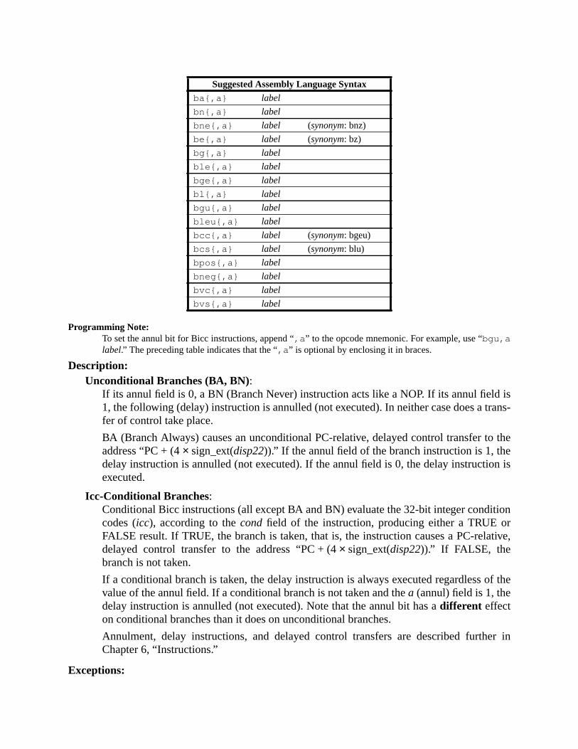
israns-
o theen is
tionrtive,
of the
er in
Programming Note:To set the annul bit for Bicc instructions, append “,a ” to the opcode mnemonic. For example, use “bgu,alabel.” The preceding table indicates that the “,a ” is optional by enclosing it in braces.
Description:Unconditional Branches (BA, BN):
If its annul field is 0, a BN (Branch Never) instruction acts like a NOP. If its annul field1, the following (delay) instruction is annulled (not executed). In neither case does a tfer of control take place.
BA (Branch Always) causes an unconditional PC-relative, delayed control transfer taddress “PC + (4× sign_ext(disp22)).” If the annul field of the branch instruction is 1, thdelay instruction is annulled (not executed). If the annul field is 0, the delay instructioexecuted.
Icc-Conditional Branches:Conditional Bicc instructions (all except BA and BN) evaluate the 32-bit integer condicodes (icc), according to thecond field of the instruction, producing either a TRUE oFALSE result. If TRUE, the branch is taken, that is, the instruction causes a PC-reladelayed control transfer to the address “PC + (4× sign_ext(disp22)).” If FALSE, thebranch is not taken.
If a conditional branch is taken, the delay instruction is always executed regardlessvalue of the annul field. If a conditional branch is not taken and thea (annul) field is 1, thedelay instruction is annulled (not executed). Note that the annul bit has adifferent effecton conditional branches than it does on unconditional branches.
Annulment, delay instructions, and delayed control transfers are described furthChapter 6, “Instructions.”
Exceptions:
Suggested Assembly Language Syntax
ba{,a} label
bn{,a} label
bne{,a} label (synonym: bnz)
be{,a} label (synonym: bz)
bg{,a} label
ble{,a} label
bge{,a} label
bl{,a} label
bgu{,a} label
bleu{,a} label
bcc{,a} label (synonym: bgeu)
bcs{,a} label (synonym: blu)
bpos{,a} label
bneg{,a} label
bvc{,a} label
bvs{,a} label

(none)
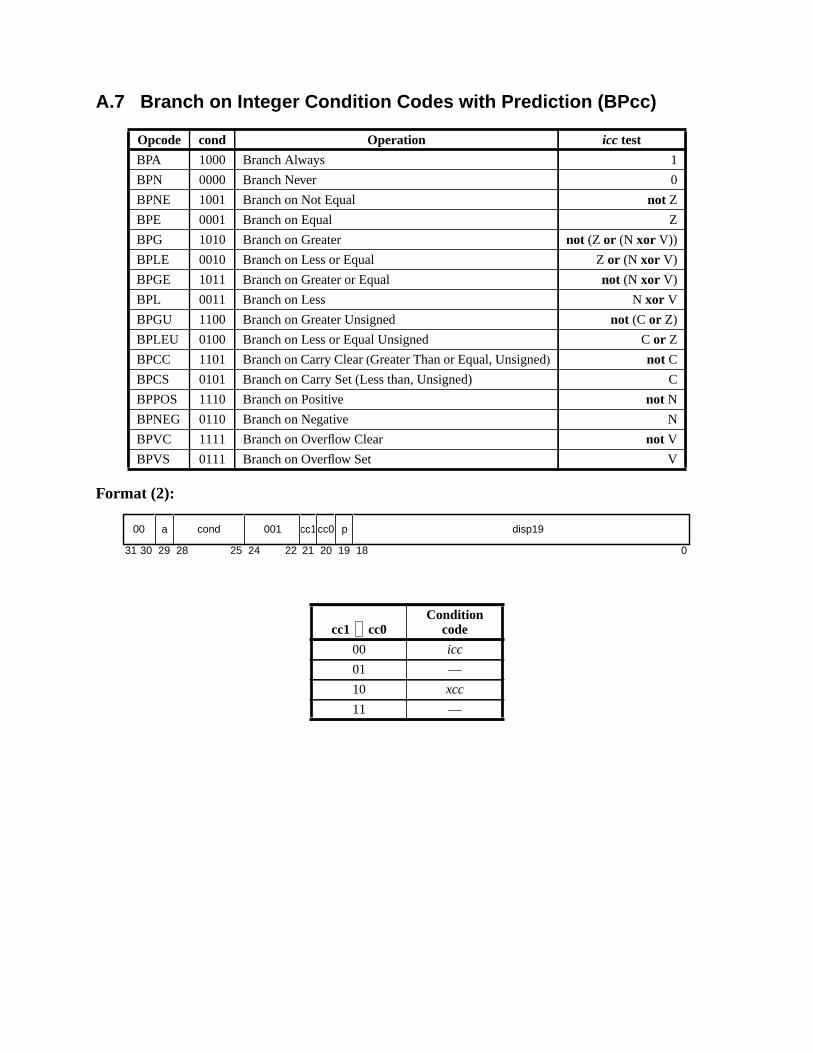
A.7 Branch on Integer Condition Codes with Prediction (BPcc)
Format (2):
Opcode cond Operation icc test
BPA 1000 Branch Always 1
BPN 0000 Branch Never 0
BPNE 1001 Branch on Not Equal not Z
BPE 0001 Branch on Equal Z
BPG 1010 Branch on Greater not (Z or (N xor V))
BPLE 0010 Branch on Less or Equal Zor (N xor V)
BPGE 1011 Branch on Greater or Equal not (N xor V)
BPL 0011 Branch on Less Nxor V
BPGU 1100 Branch on Greater Unsigned not (C or Z)
BPLEU 0100 Branch on Less or Equal Unsigned Cor Z
BPCC 1101 Branch on Carry Clear(Greater Than or Equal, Unsigned) not C
BPCS 0101 Branch on Carry Set (Less than, Unsigned) C
BPPOS 1110 Branch on Positive not N
BPNEG 0110 Branch on Negative N
BPVC 1111 Branch on Overflow Clear not V
BPVS 0111 Branch on Overflow Set V
cc1 cc0Condition
code
00 icc
01 —
10 xcc
11 —
31 1924 18 02530 29 28 22 21 20
00 a cond 001 cc1 p disp19cc0
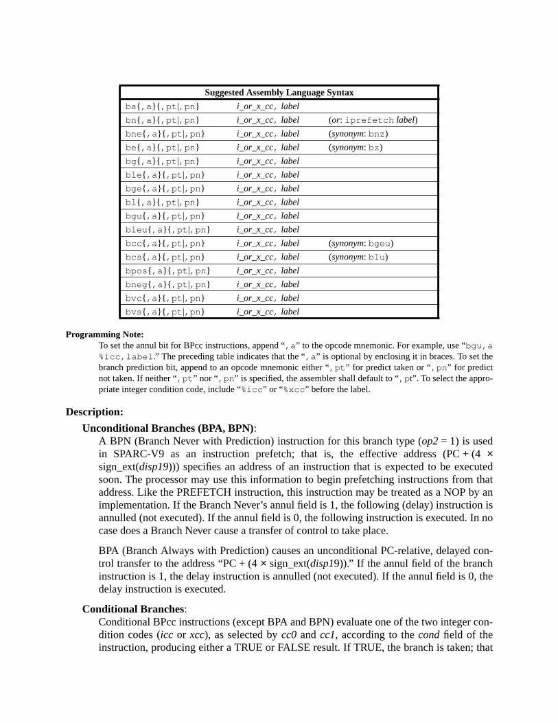
e
4utedthat
by anisno
con-
, the
con-
that
Programming Note:To set the annul bit for BPcc instructions, append “,a ” to the opcode mnemonic. For example, use “bgu,a%icc,label .” The preceding table indicates that the “,a ” is optional by enclosing it in braces. To set thbranch prediction bit, append to an opcode mnemonic either “,pt ” for predict taken or “,pn ” for predictnot taken. If neither “,pt ” nor “ ,pn ” is specified, the assembler shall default to “,p t”. To select the appro-priate integer condition code, include “%icc ” or “%xcc” before the label.
Description:
Unconditional Branches (BPA, BPN):A BPN (Branch Never with Prediction) instruction for this branch type (op2= 1) is usedin SPARC-V9 as an instruction prefetch; that is, the effective address (PC + (×sign_ext(disp19))) specifies an address of an instruction that is expected to be execsoon. The processor may use this information to begin prefetching instructions fromaddress. Like the PREFETCH instruction, this instruction may be treated as a NOPimplementation. If the Branch Never’s annul field is 1, the following (delay) instructionannulled (not executed). If the annul field is 0, the following instruction is executed. Incase does a Branch Never cause a transfer of control to take place.
BPA (Branch Always with Prediction) causes an unconditional PC-relative, delayedtrol transfer to the address “PC + (4× sign_ext(disp19)).” If the annul field of the branchinstruction is 1, the delay instruction is annulled (not executed). If the annul field is 0delay instruction is executed.
Conditional Branches:Conditional BPcc instructions (except BPA and BPN) evaluate one of the two integerdition codes (icc or xcc), as selected bycc0 andcc1, according to thecondfield of theinstruction, producing either a TRUE or FALSE result. If TRUE, the branch is taken;
Suggested Assembly Language Syntax
ba{ ,a }{ ,pt |,pn } i_or_x_cc, label
bn{ ,a }{ ,pt |,pn } i_or_x_cc, label (or: iprefetch label)
bne { ,a }{ ,pt |,pn } i_or_x_cc, label (synonym: bnz )
be{ ,a }{ ,pt |,pn } i_or_x_cc, label (synonym: bz )
bg{ ,a }{ ,pt |,pn } i_or_x_cc, label
ble { ,a }{ ,pt |,pn } i_or_x_cc, label
bge { ,a }{ ,pt |,pn } i_or_x_cc, label
bl { ,a }{ ,pt |,pn } i_or_x_cc, label
bgu { ,a }{ ,pt |,pn } i_or_x_cc, label
bleu { ,a }{ ,pt |,pn } i_or_x_cc, label
bcc { ,a }{ ,pt |,pn } i_or_x_cc, label (synonym: bgeu )
bcs { ,a }{ ,pt |,pn } i_or_x_cc, label (synonym: blu )
bpos { ,a }{ ,pt |,pn } i_or_x_cc, label
bneg { ,a }{ ,pt |,pn } i_or_x_cc, label
bvc { ,a }{ ,pt |,pn } i_or_x_cc, label
bvs { ,a }{ ,pt |,pn } i_or_x_cc, label

+ (4
of the
cted
d fur-
is, the instruction causes a PC-relative, delayed control transfer to the address “PC×sign_ext(disp19)).” If FALSE, the branch is not taken.
If a conditional branch is taken, the delay instruction is always executed regardlessvalue of the annul field. If a conditional branch is not taken and thea (annul) field is 1, thedelay instruction is annulled (not executed). Note that the annul bit has adifferent effectfor conditional branches than it does for unconditional branches.
The predict bit (p) is used to give the hardware a hint about whether the branch is expeto be taken. A 1 in thep bit indicates that the branch is expected to be taken; a 0 indicatesthat the branch is expected not to be taken.
Annulment, delay instructions, prediction, and delayed control transfers are describether in Chapter 6, “Instructions.”
Exceptions:illegal_instruction (cc1 cc0= 012 or 112)

dress
byros to
into
A.8 Call and Link
Format (1):
Description:
The CALL instruction causes an unconditional, delayed, PC-relative control transfer to adPC + (4× sign_ext(disp30)). Since the word displacement (disp30) field is 30 bits wide, the targetaddress lies within a range of –231 to +231 – 4 bytes. The PC-relative displacement is formedsign-extending the 30-bit word displacement field to 62 bits and appending two low-order zeobtain a 64-bit byte displacement.
The CALL instruction also writes the value of PC, which contains the address of the CALL,r[15] (out register 7). The high-order 32-bits of the PC value stored inr[15] are implementation-dependent when PSTATE.AM = 1 (impl. dep. #125). The value written intor[15] is visible to theinstruction in the delay slot.
Exceptions:(none)
Opcode op Operation
CALL 01 Call and Link
Suggested Assembly Language Syntax
call label
31 030 29
01 disp30
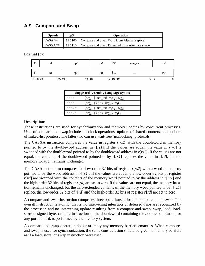
cesses.updates
er
ca-
ap. Theed by, load-ion, or
e-arriers
A.9 Compare and Swap
Format (3):
Description:These instructions are used for synchronization and memory updates by concurrent proUses of compare-and-swap include spin-lock operations, updates of shared counters, andof linked-list pointers. The latter two can use wait-free (nonlocking) protocols.
The CASXA instruction compares the value in registerr[rs2] with the doubleword in memorypointed to by the doubleword address inr[rs1]. If the values are equal, the value inr[rd] isswapped with the doubleword pointed to by the doubleword address inr[rs1]. If the values are notequal, the contents of the doubleword pointed to byr[rs1] replaces the value inr[rd], but thememory location remains unchanged.
The CASA instruction compares the low-order 32 bits of registerr[rs2] with a word in memorypointed to by the word address inr[rs1]. If the values are equal, the low-order 32 bits of registr[rd] are swapped with the contents of the memory word pointed to by the address inr[rs1] andthe high-order 32 bits of registerr[rd] are set to zero. If the values are not equal, the memory lotion remains unchanged, but the zero-extended contents of the memory word pointed to byr[rs1]replace the low-order 32 bits ofr[rd] and the high-order 32 bits of registerr[rd] are set to zero.
A compare-and-swap instruction comprises three operations: a load, a compare, and a swoverall instruction is atomic; that is, no intervening interrupts or deferred traps are recognizthe processor, and no intervening update resulting from a compare-and-swap, swap, loadstore unsigned byte, or store instruction to the doubleword containing the addressed locatany portion of it, is performed by the memory system.
A compare-and-swap operation doesnot imply any memory barrier semantics. When comparand-swap is used for synchronization, the same consideration should be given to memory bas if a load, store, or swap instruction were used.
Opcode op3 Operation
CASAPASI 11 1100 Compare and Swap Word from Alternate space
CASXAPASI 11 1110 Compare and Swap Extended from Alternate space
Suggested Assembly Language Syntax
casa [regrs1] imm_asi, regrs2, regrd
casa [regrs1] %asi , regrs2, regrd
casxa [regrs1] imm_asi, regrs2, regrd
casxa [regrs1] %asi , regrs2, regrd
31 141924 18 13 12 5 4 02530 29
11 rd op3 rs1 i=0 imm_asi rs2
11 rd op3 rs1 i=1 — rs2

ues in
I
mory
though
ble forLittle
hetic
A compare-and-swap operation behaves as if it performs a store, either of a new value fromr[rd]or of the previous value in memory. The addressed location must be writable, even if the valmemory andr[rs2] are not equal.
If i = 0, the address space of the memory location is specified in theimm_asifield; if i = 1, theaddress space is specified in the ASI register.
A mem_address_not_aligned exception is generated if the address inr[rs1] is not properly aligned.CASXA and CASA cause aprivileged_action exception if PSTATE.PRIV = 0 and bit 7 of the ASis zero.
The coherence and atomicity of memory operations between processors and I/O DMA meaccesses are implementation-dependent (impl. dep #120).
Implementation Note:An implementation might cause an exception due to an error during the store memory access, eventhere was no error during the load memory access.
Programming Note:Compare and Swap (CAS) and Compare and Swap Extended (CASX) synthetic instructions are availa“big endian” memory accesses. Compare and Swap Little (CASL) and Compare and Swap Extended(CASXL) synthetic instructions are available for “little endian” memory accesses. See G.3, “SyntInstructions,” for these synthetic instructions’ syntax.
The compare-and-swap instructions do not affect the condition codes.
Exceptions:privileged_actionmem_address_not_aligneddata_access_exceptiondata_access_MMU_missdata_access_protectiondata_access_errorasync_data_error

t are
ion.
A.10 Divide (64-bit / 32-bit)
Format (3):
Description:
The divide instructions perform 64-bit by 32-bit division, producing a 32-bit result. Ifi = 0, theycompute “(Y lower 32 bits of r[rs1]) ÷ lower 32 bits of r[rs2].” Otherwise (i.e., ifi = 1), thedivide instructions compute “(Y lower 32 bits of r[rs1]) ÷ lower 32 bits ofsign_ext(simm13).”In either case, if overflow does not occur, the less significant 32 bits of the integer quotiensign-or zero-extended to 64 bits and are written intor[rd].
The contents of the Y register are undefined after any 64-bit by 32-bit integer divide operat
Unsigned Divide:
Unsigned divide (UDIV, UDIVcc) assumes an unsigned integer doubleword dividend (Ylower32 bits of r[rs1]) and an unsigned integer word divisor (lower 32 bits of r[rs2] or lower 32 bits ofsign_ext(simm13)) and computes an unsigned integer word quotient (r[rd]). Immediate values insimm13 are in the ranges 0..212– 1 and 232– 212..232– 1 for unsigned divide instructions.
Unsigned division rounds an inexact rational quotient toward zero .
Opcode op3 Operation
UDIVD 00 1110 Unsigned Integer Divide
SDIVD 00 1111 Signed Integer Divide
UDIVccD 01 1110 Unsigned Integer Divide and modify cc’s
SDIVccD 01 1111 Signed Integer Divide and modify cc’s
Suggested Assembly Language Syntax
udiv regrs1, reg_or_imm, regrdsdiv regrs1, reg_or_imm, regrdudivcc regrs1, reg_or_imm, regrdsdivcc regrs1, reg_or_imm, regrd
The UDIV, UDIVcc, SDIV, and SDIVcc instructions are deprecated; they are pro-vided only for compatibility with previous versions of the architecture. They shouldnot be used in new SPARC-V9 software. It is recommended that the UDIVX andSDIVX instructions be used in their place.
31 24 02530 29 19 18
rd10 op3 —
14 13 12 5 4
rs1 rs2i=0
rd10 op3 rs1 simm13i=1
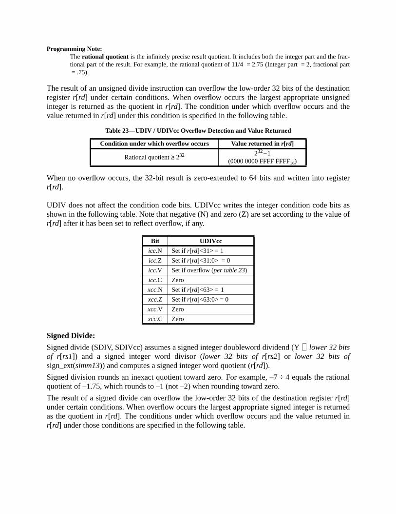
rac-l part
ationgnede
ister
s aslue of
turnedin
Programming Note:The rational quotient is the infinitely precise result quotient. It includes both the integer part and the ftional part of the result. For example, the rational quotient of 11/4 = 2.75 (Integer part = 2, fractiona= .75).
The result of an unsigned divide instruction can overflow the low-order 32 bits of the destinregisterr[rd] under certain conditions. When overflow occurs the largest appropriate unsiinteger is returned as the quotient inr[rd]. The condition under which overflow occurs and thvalue returned inr[rd] under this condition is specified in the following table.
When no overflow occurs, the 32-bit result is zero-extended to 64 bits and written into regr[rd].
UDIV does not affect the condition code bits. UDIVcc writes the integer condition code bitshown in the following table. Note that negative (N) and zero (Z) are set according to the var[rd] after it has been set to reflect overflow, if any.
Signed Divide:
Signed divide (SDIV, SDIVcc) assumes a signed integer doubleword dividend (Ylower 32 bitsof r[rs1]) and a signed integer word divisor (lower 32 bits of r[rs2] or lower 32 bits ofsign_ext(simm13)) and computes a signed integer word quotient (r[rd]).
Signed division rounds an inexact quotient toward zero. For example, –7÷ 4 equals the rationalquotient of –1.75, which rounds to –1 (not –2) when rounding toward zero.
The result of a signed divide can overflow the low-order 32 bits of the destination registerr[rd]under certain conditions. When overflow occurs the largest appropriate signed integer is reas the quotient inr[rd]. The conditions under which overflow occurs and the value returnedr[rd] under those conditions are specified in the following table.
Table 23—UDIV / UDIVcc Overflow Detection and Value Returned
Condition under which overflow occurs Value returned inr[rd]
Rational quotient≥ 232 232−1(0000 0000 FFFF FFFF16)
Bit UDIVcc
icc.N Set ifr[rd]<31> = 1
icc.Z Set ifr[rd]<31:0> = 0
icc.V Set if overflow (per table 23)
icc.C Zero
xcc.N Set ifr[rd]<63> = 1
xcc.Z Set ifr[rd]<63:0> = 0
xcc.V Zero
xcc.C Zero

ister
ts aslue of
When no overflow occurs, the 32-bit result is sign-extended to 64 bits and written into regr[rd].
SDIV does not affect the condition code bits. SDIVcc writes the integer condition code bishown in the following table. Note that negative (N) and zero (Z) are set according to the var[rd] after it has been set to reflect overflow, if any.
Exceptions:division_by_zero
Table 24—SDIV / SDIVcc Overflow Detection and Value Returned
Condition under which overflow occurs Value returned inr[rd]
Rational quotient≥ 231 231−1(0000 0000 7FFF FFFF16)
Rational quotient≤ -231−1−231
(FFFF FFFF 8000 000016)
Bit SDIVcc
icc.N Set ifr[rd]<31> = 1
icc.Z Set ifr[rd]<31:0> = 0
icc.V Set if overflow (per table 24)
icc.C Zero
xcc.N Set ifr[rd]<63]> = 1
xcc.Z Set ifr[rd]<63:0> = 0
xcc.V Zero
xcc.C Zero

, and
ro-
A.11 DONE and RETRY
Format (3):
Description:
The DONE and RETRY instructions restore the saved state from TSTATE (CWP, ASI, CCRPSTATE), set PC and nPC, and decrement TL.
The RETRY instruction resumes execution with the trapped instruction by setting PC←TPC[TL](the saved value of PC on trap) and nPC←TNPC[TL] (the saved value of nPC on trap).
The DONE instruction skips the trapped instruction by setting PC←TNPC[TL] andnPC←TNPC[TL]+4.
Execution of a DONE or RETRY instruction in the delay slot of a control-transfer instruction pduces undefined results.
Programming Note:The DONE and RETRY instructions should be used to return from privileged trap handlers.
Exceptions:privileged_opcodeillegal_instruction (if TL = 0 or fcn= 2..31)
Opcode op3 fcn Operation
DONEP 11 1110 0 Return from Trap (skip trapped instruction)
RETRYP 11 1110 1 Return from Trap (retry trapped instruction)
— 11 1110 2..31 Reserved
Suggested Assembly Language Syntax
done
retry
10 op3fcn —
31 1924 18 02530 29
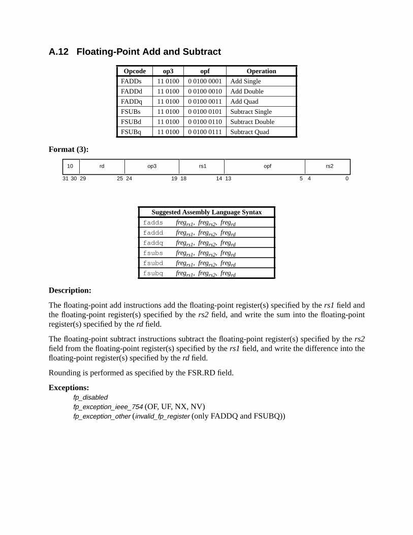
t
e
A.12 Floating-Point Add and Subtract
Format (3):
Description:
The floating-point add instructions add the floating-point register(s) specified by thers1 field andthe floating-point register(s) specified by thers2 field, and write the sum into the floating-poinregister(s) specified by therd field.
The floating-point subtract instructions subtract the floating-point register(s) specified by thrs2field from the floating-point register(s) specified by thers1 field, and write the difference into thefloating-point register(s) specified by therd field.
Rounding is performed as specified by the FSR.RD field.
Exceptions:fp_disabledfp_exception_ieee_754 (OF, UF, NX, NV)fp_exception_other (invalid_fp_register (only FADDQ and FSUBQ))
Opcode op3 opf Operation
FADDs 11 0100 0 0100 0001 Add Single
FADDd 11 0100 0 0100 0010 Add Double
FADDq 11 0100 0 0100 0011 Add Quad
FSUBs 11 0100 0 0100 0101 Subtract Single
FSUBd 11 0100 0 0100 0110 Subtract Double
FSUBq 11 0100 0 0100 0111 Subtract Quad
Suggested Assembly Language Syntax
fadds fregrs1, fregrs2, fregrd
faddd fregrs1, fregrs2, fregrd
faddq fregrs1, fregrs2, fregrd
fsubs fregrs1, fregrs2, fregrd
fsubd fregrs1, fregrs2, fregrd
fsubq fregrs1, fregrs2, fregrd
10 op3 rs2rd rs1
31 141924 18 13 02530 29 4
opf
5
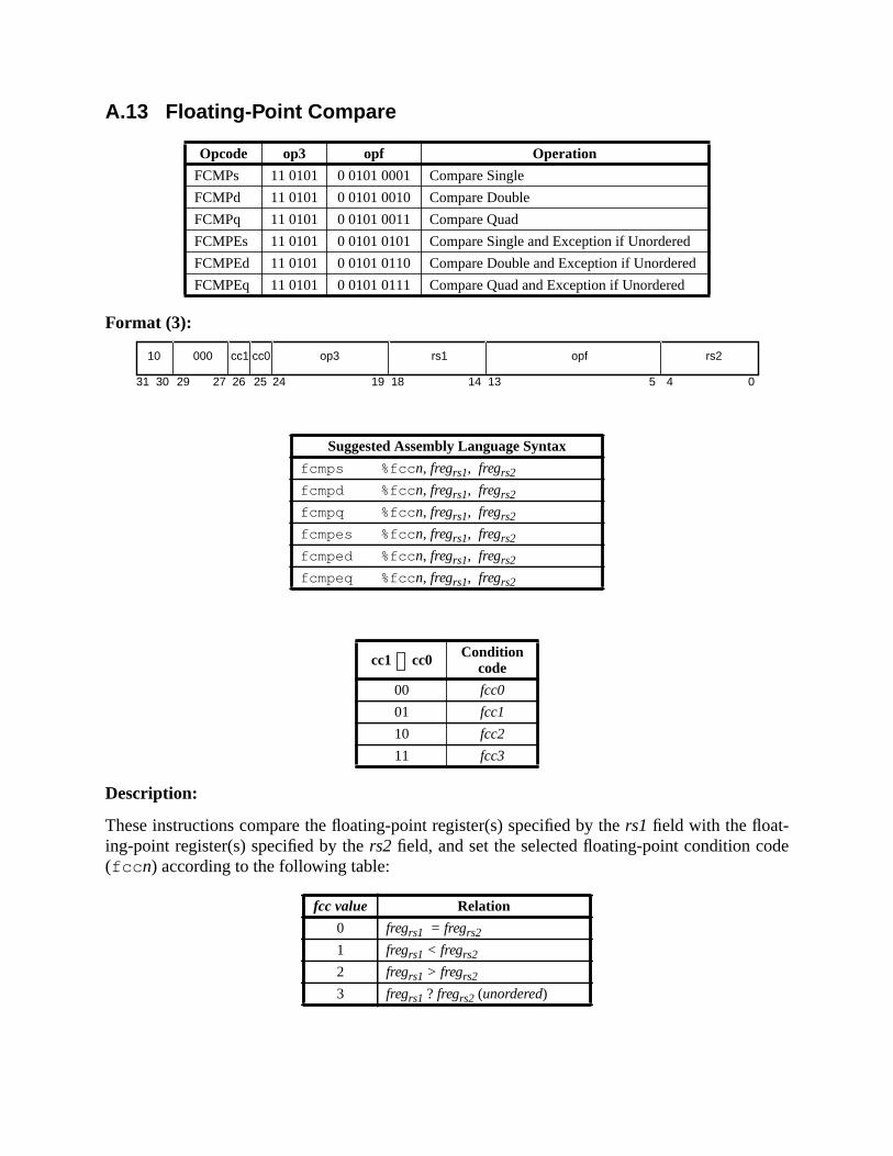
de
A.13 Floating-Point Compare
Format (3):
Description:
These instructions compare the floating-point register(s) specified by thers1 field with the float-ing-point register(s) specified by thers2 field, and set the selected floating-point condition co(fcc n) according to the following table:
Opcode op3 opf Operation
FCMPs 11 0101 0 0101 0001 Compare Single
FCMPd 11 0101 0 0101 0010 Compare Double
FCMPq 11 0101 0 0101 0011 Compare Quad
FCMPEs 11 0101 0 0101 0101 Compare Single and Exception if Unordered
FCMPEd 11 0101 0 0101 0110 Compare Double and Exception if Unordered
FCMPEq 11 0101 0 0101 0111 Compare Quad and Exception if Unordered
Suggested Assembly Language Syntax
fcmps %fcc n, fregrs1, fregrs2
fcmpd %fcc n, fregrs1, fregrs2
fcmpq %fcc n, fregrs1, fregrs2
fcmpes %fcc n, fregrs1, fregrs2
fcmped %fcc n, fregrs1, fregrs2
fcmpeq %fcc n, fregrs1, fregrs2
cc1 cc0 Conditioncode
00 fcc0
01 fcc1
10 fcc2
11 fcc3
fcc value Relation
0 fregrs1 = fregrs2
1 fregrs1 < fregrs2
2 fregrs1 > fregrs2
3 fregrs1 ? fregrs2 (unordered)
10 op3 rs2000 rs1
31 141924 18 13 02530 29 4
opf
52627
cc1 cc0

dition
truc-
ration
RC-
The “?” in the above table indicates that the comparison is unordered. The unordered conoccurs when one or both of the operands to the compare is a signaling or quiet NaN.
The “compare and cause exception if unordered” (FCMPEs, FCMPEd, and FCMPEq) instions cause an invalid (NV) exception if either operand is a NaN.
FCMP causes an invalid (NV) exception if either operand is a signaling NaN.
Compatibility Note:Unlike SPARC-V8, SPARC-V9 does not require an instruction between a floating-point compare opeand a floating-point branch (FBfcc, FBPfcc).
Compatibility Note:SPARC-V8 floating-point compare instructions are required to have a zero in ther[rd] field. In SPARC-V9,bits 26 and 25 of ther[rd] field are used to specify the floating-point condition code to be set. Legal SPAV8 code will work on SPARC-V9 because the zeroes in ther[rd] field are interpreted asfcc0 , and theFBfcc instruction branches based onfcc0 .
Exceptions:fp_disabledfp_exception_ieee_754 (NV)fp_exception_other (invalid_fp_register (FCMPq, FCMPEq only))

er(s)
pec-
FSR
size,int
A.14 Convert Floating-Point to Integer
Format (3):
Description:
FsTOx, FdTOx, and FqTOx convert the floating-point operand in the floating-point registspecified byrs2 to a 64-bit integer in the floating-point register(s) specified byrd.
FsTOi, FdTOi, and FqTOi convert the floating-point operand in the floating-point register(s) sified by rs2 to a 32-bit integer in the floating-point register specified byrd.
The result is always rounded toward zero; that is, the rounding direction (RD) field of theregister is ignored.
If the floating-point operand’s value is too large to be converted to an integer of the specifiedor is a NaN or infinity, an invalid (NV) exception occurs. The value written into the floating-poregister(s) specified byrd in these cases is defined in B.5, “Integer Overflow Definition.”
Exceptions:fp_disabledfp_exception_ieee_754 (NV, NX)fp_exception_other (invalid_fp_register (FqTOi, FqTOx only))
Opcode op3 opf Operation
FsTOx 11 0100 0 1000 0001 Convert Single to 64-bit Integer
FdTOx 11 0100 0 1000 0010 Convert Double to 64-bit Integer
FqTOx 11 0100 0 1000 0011 Convert Quad to 64-bit Integer
FsTOi 11 0100 0 1101 0001 Convert Single to 32-bit Integer
FdTOi 11 0100 0 1101 0010 Convert Double to 32-bit Integer
FqTOi 11 0100 0 1101 0011 Convert Quad to 32-bit Integer
Suggested Assembly Language Syntax
fstox fregrs2, fregrd
fdtox fregrs2, fregrd
fqtox fregrs2, fregrd
fstoi fregrs2, fregrd
fdtoi fregrs2, fregrd
fqtoi fregrs2, fregrd
10 op3 rs2rd —
31 141924 18 13 02530 29 4
opf
5

ed bying-
d NX
aling
rting
A.15 Convert Between Floating-Point Formats
Format (3):
Description:
These instructions convert the floating-point operand in the floating-point register(s) specifirs2 to a floating-point number in the destination format. They write the result into the floatpoint register(s) specified byrd.
Rounding is performed as specified by the FSR.RD field.
FqTOd, FqTOs, and FdTOs (the “narrowing” conversion instructions) can raise OF, UF, anexceptions. FdTOq, FsTOq, and FsTOd (the “widening” conversion instructions) cannot.
Any of these six instructions can trigger an NV exception if the source operand is a signNaN.
B.2.1, “Untrapped Result in Different Format from Operands,” defines the rules for conveNaNs from one floating-point format to another.
Exceptions:fp_disabledfp_exception_ieee_754 (OF, UF, NV, NX)fp_exception_other (invalid_fp_register) (FsTOq, FdTOq, FqTOs, FqTOd)
Opcode op3 opf Operation
FsTOd 11 0100 0 1100 1001 Convert Single to Double
FsTOq 11 0100 0 1100 1101 Convert Single to Quad
FdTOs 11 0100 0 1100 0110 Convert Double to Single
FdTOq 11 0100 0 1100 1110 Convert Double to Quad
FqTOs 11 0100 0 1100 0111 Convert Quad to Single
FqTOd 11 0100 0 1100 1011 Convert Quad to Double
Suggested Assembly Language Syntax
fstod fregrs2, fregrd
fstoq fregrs2, fregrd
fdtos fregrs2, fregrd
fdtoq fregrs2, fregrd
fqtos fregrs2, fregrd
fqtod fregrs2, fregrd
10 op3 rs2rd —
31 141924 18 13 02530 29 4
opf
5
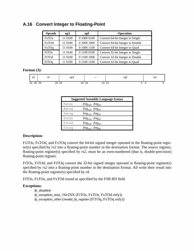
egis-ter,
on)
er(s)to
A.16 Convert Integer to Floating-Point
Format (3):
Description:
FxTOs, FxTOd, and FxTOq convert the 64-bit signed integer operand in the floating-point rter(s) specified byrs2 into a floating-point number in the destination format. The source regisfloating-point register(s) specified byrs2, must be an even-numbered (that is, double-precisifloating-point register.
FiTOs, FiTOd, and FiTOq convert the 32-bit signed integer operand in floating-point registspecified byrs2 into a floating-point number in the destination format. All write their result inthe floating-point register(s) specified byrd.
FiTOs, FxTOs, and FxTOd round as specified by the FSR.RD field.
Exceptions:fp_disabledfp_exception_ieee_754 (NX (FiTOs, FxTOs, FxTOd only))fp_exception_other (invalid_fp_register (FiTOq, FxTOq only))
Opcode op3 opf Operation
FxTOs 11 0100 0 1000 0100 Convert 64-bit Integer to Single
FxTOd 11 0100 0 1000 1000 Convert 64-bit Integer to Double
FxTOq 11 0100 0 1000 1100 Convert 64-bit Integer to Quad
FiTOs 11 0100 0 1100 0100 Convert 32-bit Integer to Single
FiTOd 11 0100 0 1100 1000 Convert 32-bit Integer to Double
FiTOq 11 0100 0 1100 1100 Convert 32-bit Integer to Quad
Suggested Assembly Language Syntax
fxtos fregrs2, fregrd
fxtod fregrs2, fregrd
fxtoq fregrs2, fregrd
fitos fregrs2, fregrd
fitod fregrs2, fregrd
fitoq fregrs2, fregrd
10 op3 rs2rd —
31 141924 18 13 02530 29 4
opf
5
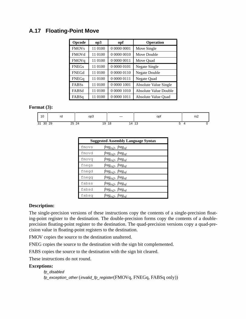
float-uble-d-pre-
A.17 Floating-Point Move
Format (3):
Description:
The single-precision versions of these instructions copy the contents of a single-precisioning-point register to the destination. The double-precision forms copy the contents of a doprecision floating-point register to the destination. The quad-precision versions copy a quacision value in floating-point registers to the destination.
FMOV copies the source to the destination unaltered.
FNEG copies the source to the destination with the sign bit complemented.
FABS copies the source to the destination with the sign bit cleared.
These instructions do not round.
Exceptions:fp_disabledfp_exception_other (invalid_fp_register(FMOVq, FNEGq, FABSq only))
Opcode op3 opf Operation
FMOVs 11 0100 0 0000 0001 Move Single
FMOVd 11 0100 0 0000 0010 Move Double
FMOVq 11 0100 0 0000 0011 Move Quad
FNEGs 11 0100 0 0000 0101 Negate Single
FNEGd 11 0100 0 0000 0110 Negate Double
FNEGq 11 0100 0 0000 0111 Negate Quad
FABSs 11 0100 0 0000 1001 Absolute Value Single
FABSd 11 0100 0 0000 1010 Absolute Value Double
FABSq 11 0100 0 0000 1011 Absolute Value Quad
Suggested Assembly Language Syntax
fmovs fregrs2, fregrd
fmovd fregrs2, fregrd
fmovq fregrs2, fregrd
fnegs fregrs2, fregrd
fnegd fregrs2, fregrd
fnegq fregrs2, fregrd
fabss fregrs2, fregrd
fabsd fregrs2, fregrd
fabsq fregrs2, fregrd
10 op3 rs2rd —
31 141924 18 13 02530 29 4
opf
5

r(s)
isionxact
ified
A.18 Floating-Point Multiply and Divide
Format (3):
Description:
The floating-point multiply instructions multiply the contents of the floating-point registespecified by thers1 field by the contents of the floating-point register(s) specified by thers2 field,and write the product into the floating-point register(s) specified by therd field.
The FsMULd instruction provides the exact double-precision product of two single-precoperands, without underflow, overflow, or rounding error. Similarly, FdMULq provides the equad-precision product of two double-precision operands.
The floating-point divide instructions divide the contents of the floating-point register(s) specby thers1field by the contents of the floating-point register(s) specified by thers2field, and writethe quotient into the floating-point register(s) specified by therd field.
Rounding is performed as specified by the FSR.RD field.
Exceptions:fp_disabledfp_exception_ieee_754 (OF, UF, DZ (FDIV only), NV, NX)fp_exception_other (invalid_fp_register (FMULq, FdMULq, and FDIVq only))
Opcode op3 opf Operation
FMULs 11 0100 0 0100 1001 Multiply Single
FMULd 11 0100 0 0100 1010 Multiply Double
FMULq 11 0100 0 0100 1011 Multiply Quad
FsMULd 11 0100 0 0110 1001 Multiply Single to Double
FdMULq 11 0100 0 0110 1110 Multiply Double to Quad
FDIVs 11 0100 0 0100 1101 Divide Single
FDIVd 11 0100 0 0100 1110 Divide Double
FDIVq 11 0100 0 0100 1111 Divide Quad
Suggested Assembly Language Syntax
fmuls fregrs1, fregrs2, fregrd
fmuld fregrs1, fregrs2, fregrd
fmulq fregrs1, fregrs2, fregrd
fsmuld fregrs1, fregrs2, fregrd
fdmulq fregrs1, fregrs2, fregrd
fdivs fregrs1, fregrs2, fregrd
fdivd fregrs1, fregrs2, fregrd
fdivq fregrs1, fregrs2, fregrd
10 op3 rs2rd rs1
31 141924 18 13 02530 29 4
opf
5
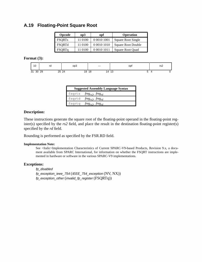
t reg-r(s)
docu-ple-
A.19 Floating-Point Square Root
Format (3):
Description:
These instructions generate the square root of the floating-point operand in the floating-poinister(s) specified by thers2 field, and place the result in the destination floating-point registespecified by therd field.
Rounding is performed as specified by the FSR.RD field.
Implementation Note:See <Italic>Implementation Characteristics of Current SPARC-V9-based Products, Revision 9.x, ament available from SPARC International, for information on whether the FSQRT instructions are immented in hardware or software in the various SPARC-V9 implementations.
Exceptions:fp_disabledfp_exception_ieee_754 (IEEE_754_exception (NV, NX))fp_exception_other (invalid_fp_register (FSQRTq))
Opcode op3 opf Operation
FSQRTs 11 0100 0 0010 1001 Square Root Single
FSQRTd 11 0100 0 0010 1010 Square Root Double
FSQRTq 11 0100 0 0010 1011 Square Root Quad
Suggested Assembly Language Syntax
fsqrts fregrs2, fregrd
fsqrtd fregrs2, fregrd
fsqrtq fregrs2, fregrd
10 op3 rs2rd —
31 141924 18 13 02530 29 4
opf
5
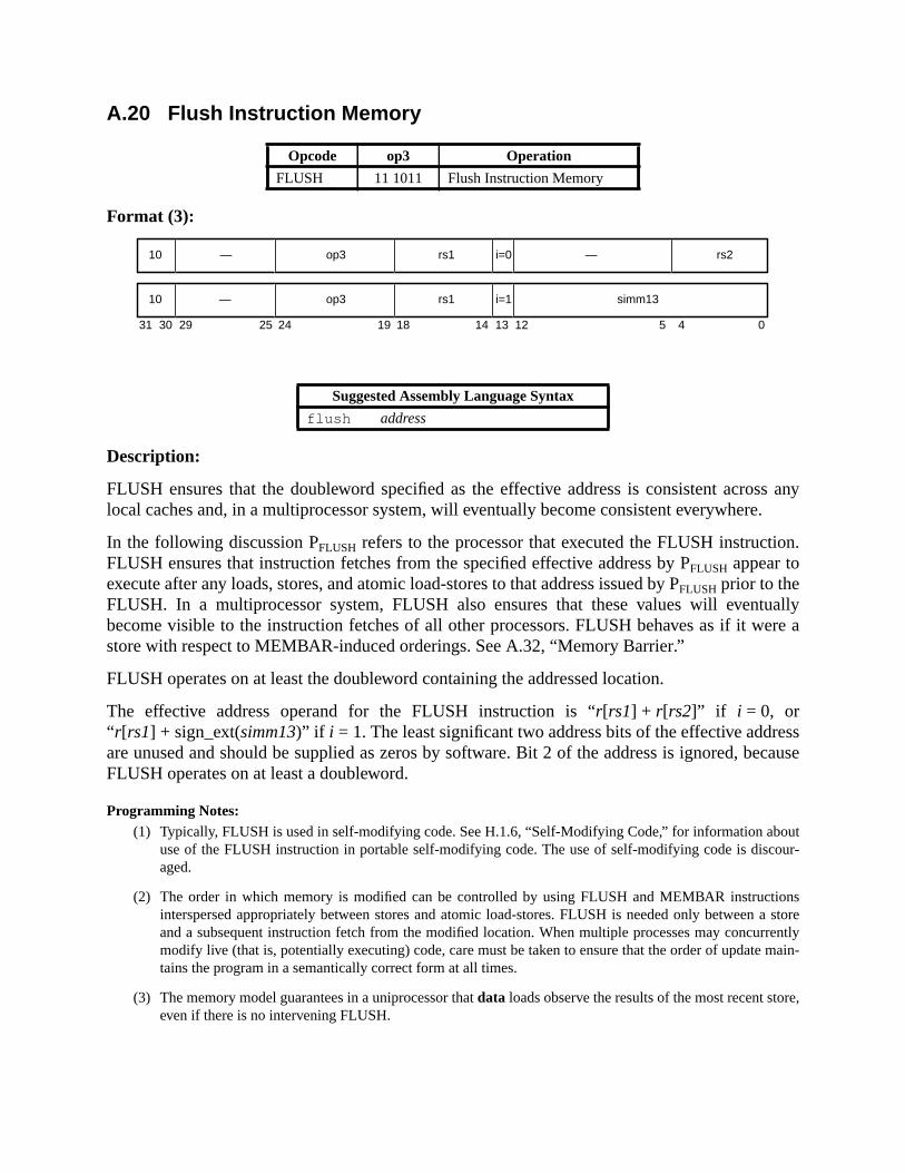
ss anye.
on.
tuallyere a
essecause
outour-
ionsa store
rrentlymain-
re,
A.20 Flush Instruction Memory
Format (3):
Description:
FLUSH ensures that the doubleword specified as the effective address is consistent acrolocal caches and, in a multiprocessor system, will eventually become consistent everywher
In the following discussion PFLUSH refers to the processor that executed the FLUSH instructiFLUSH ensures that instruction fetches from the specified effective address by PFLUSH appear toexecute after any loads, stores, and atomic load-stores to that address issued by PFLUSH prior to theFLUSH. In a multiprocessor system, FLUSH also ensures that these values will evenbecome visible to the instruction fetches of all other processors. FLUSH behaves as if it wstore with respect to MEMBAR-induced orderings. See A.32, “Memory Barrier.”
FLUSH operates on at least the doubleword containing the addressed location.
The effective address operand for the FLUSH instruction is “r[rs1] + r[rs2]” if i = 0, or“ r[rs1] + sign_ext(simm13)” if i = 1. The least significant two address bits of the effective addrare unused and should be supplied as zeros by software. Bit 2 of the address is ignored, bFLUSH operates on at least a doubleword.
Programming Notes:(1) Typically, FLUSH is used in self-modifying code. See H.1.6, “Self-Modifying Code,” for information ab
use of the FLUSH instruction in portable self-modifying code. The use of self-modifying code is discaged.
(2) The order in which memory is modified can be controlled by using FLUSH and MEMBAR instructinterspersed appropriately between stores and atomic load-stores. FLUSH is needed only betweenand a subsequent instruction fetch from the modified location. When multiple processes may concumodify live (that is, potentially executing) code, care must be taken to ensure that the order of updatetains the program in a semantically correct form at all times.
(3) The memory model guarantees in a uniprocessor thatdata loads observe the results of the most recent stoeven if there is no intervening FLUSH.
Opcode op3 Operation
FLUSH 11 1011 Flush Instruction Memory
Suggested Assembly Language Syntax
flush address
31 24 02530 29 19 18
—10 op3 —
14 13 12 5 4
rs1 rs2i=0
10 op3 rs1 simm13i=1—
hard-g the
(impl.
H maytine forries ofh the
-ndent
(4) FLUSH may be time-consuming. Some implementations may trap rather than implement FLUSH inware. In a multiprocessor configuration, FLUSH requires all processors that may be referencinaddressed doubleword to flush their instruction caches, a potentially disruptive activity.
(5) In a multiprocessor system, the time it takes for a FLUSH to take effect is implementation-dependentdep. #122). No mechanism is provided to ensure or test completion.
(6) Because FLUSH is designed to act on a doubleword, and because, on some implementations, FLUStrap to system software, it is recommended that system software provide a user-callable service rouflushing arbitrarily sized regions of memory. On some implementations, this routine would issue a seFLUSH instructions; on others, it might issue a single trap to system software that would then flusentire region.
Implementation Notes:
(1) IMPL. DEP. #42: If FLUSH is not implemented in hardware, it causes an illegal_instruction excep-tion and the function of FLUSH is performed by system software. Whether FLUSH traps is imple-mentation-dependent.
(2) The effect of a FLUSH instruction as observed from PFLUSH is immediate. Other processors in a multiprocessor system eventually will see the effect of the FLUSH, but the latency is implementation-depe(impl. dep. #122).
Exceptions:(none)

moryactivenly
gister
onen isthe
HWdow
A.21 Flush Register Windows
Format (3):
Description:
FLUSHW causes all active register windows except the current window to be flushed to meat locations determined by privileged software. FLUSHW behaves as a NOP if there are nowindows other than the current window. At the completion of the FLUSHW instruction, the oactive register window is the current one.
Programming Note:The FLUSHW instruction can be used by application software to switch memory stacks or examine recontents for previous stack frames.
FLUSHW acts as a NOP if CANSAVE = NWINDOWS – 2. Otherwise, there is more thanactive window, so FLUSHW causes a spill exception. The trap vector for the spill exceptiobased on the contents of OTHERWIN and WSTATE. The spill trap handler is invoked withCWP set to the window to be spilled (that is, (CWP+ CANSAVE + 2) mod NWINDOWS). See6.3.6, “Register Window Management Instructions.”
Programming Note:Typically, the spill handler will save a window on a memory stack and return to reexecute the FLUSinstruction. Thus, FLUSHW will trap and reexecute until all active windows other than the current winhave been spilled.
Exceptions:spill_n_normalspill_n_other
Opcode op3 Operation
FLUSHW 10 1011 Flush Register Windows
Suggested Assembly Language Syntax
flushw
31 24 02530 29 19 18
—10 op3 —
14 13 12
— i=0

A.22 Illegal Instruction Trap
Format (2):
Description:
The ILLTRAP instruction causes anillegal_instruction exception. Theconst22value is ignored bythe hardware; specifically, this field isnot reserved by the architecture for any future use.
Compatibility Note:Except for its name, this instruction is identical to the SPARC-V8 UNIMP instruction.
Exceptions:illegal_instruction
Opcode op op2 Operation
ILLTRAP 00 000 illegal_instruction trap
Suggested Assembly Language Syntax
illtrap const22
00 000 const22—
31 2124 02530 29 22

nding
A.23 Implementation-Dependent Instructions
Format (3):
Description:
IMPL. DEP. #106: The IMPDEP1 and IMPDEP2 instructions are completely implementation-dependent.Implementation-dependent aspects include their operation, the interpretation of bits 29..25 and 18..0 intheir encodings, and which (if any) exceptions they may cause.
See I.1.2, “Implementation-Dependent and Reserved Opcodes,” for information about extethe SPARC-V9 instruction set using the implementation-dependent instructions.
Compatibility Note:These instructions replace the CPopn instructions in SPARC-V8.
Exceptions:illegal_instruction (if the implementation does not define the instructions)implementation-dependent (if the implementation defines the instructions)
Opcode op3 Operation
IMPDEP1 11 0110 Implementation-Dependent Instruction 1
IMPDEP2 11 0111 Implementation-Dependent Instruction 2
10 op3 impl-depimpl-dep
31 1824 02530 29 19

en by
, into
MPL
A.24 Jump and Link
Format (3):
Description:
The JMPL instruction causes a register-indirect delayed control transfer to the address giv“ r[rs1] + r[rs2]” if i field = 0, or “r[rs1] + sign_ext(simm13)” if i = 1.
The JMPL instruction copies the PC, which contains the address of the JMPL instructionregisterr[rd]. The high-order 32-bits of the PC value stored inr[rd] are implementation-depen-dent when PSTATE.AM = 1 (impl. dep. #125). The value written intor[rd] is visible to theinstruction in the delay slot.
If either of the low-order two bits of the jump address is nonzero, amem_address_not_alignedexception occurs.
Programming Note:A JMPL instruction withrd = 15 functions as a register-indirect call using the standard link register.
JMPL with rd = 0 can be used to return from a subroutine. The typical return address is “r[31] + 8,” if anonleaf routine (one that uses the SAVE instruction) is entered by a CALL instruction, or “r[15] + 8” if aleaf routine (one that does not use the SAVE instruction) is entered by a CALL instruction or by a Jinstruction withrd = 15.
Exceptions:mem_address_not_aligned
Opcode op3 Operation
JMPL 11 1000 Jump and Link
Suggested Assembly Language Syntax
jmpl address, regrd
31 24 02530 29 19 18
rd10 op3
14 13 12 5 4
rs1 rs2i=0
rd10 op3 rs1 simm13i=1
—

rom
ory
A.25 Load Floating-Point
† Encoded floating-point register value, as described in 5.1.4.1
Format (3):
Description:
The load single floating-point instruction (LDF) copies a word from memory intof[rd].
The load doubleword floating-point instruction (LDDF) copies a word-aligned doubleword fmemory into a double-precision floating-point register.
The load quad floating-point instruction (LDQF) copies a word-aligned quadword from meminto a quad-precision floating-point register.
Opcode op3 rd Operation
LDF 10 0000
0..31 Load Floating-Point Register
LDDF 10 0011
† Load Double Floating-Point Register
LDQF 10 0010
† Load Quad Floating-Point Register
LDFSRD 10 0001
0 Load Floating-Point State Register Lower
LDXFSR 10 0001
1 Load Floating-Point State Register
— 10 0001
2..31 Reserved
Suggested Assembly Language Syntax
ld [address], fregrd
ldd [address], fregrd
ldq [address], fregrd
ld [address], %fsr
ldx [address], %fsr
The LDFSR instruction is deprecated; it is provided only for compatibility withprevious versions of the architecture. It should not be used in new SPARC-V9 soft-ware. It is recommended that the LDXFSR instruction be used in its place.
31 24 02530 29 19 18 14 13 12 5 4
rd11 op3 rs1 simm13i=1
rd11 op3 rs1 i=0 — rs2

ionslower
thatFSR.
n isload
and
erminelignedly when
The load floating-point state register lower instruction (LDFSR) waits for all FPop instructthat have not finished execution to complete, and then loads a word from memory into the32 bits of the FSR. The upper 32 bits of FSR are unaffected by LDFSR.
The load floating-point state register instruction (LDXFSR) waits for all FPop instructionshave not finished execution to complete, and then loads a doubleword from memory into the
Compatibility Note:SPARC-V9 supports two different instructions to load the FSR; the SPARC-V8 LDFSR instructiodefined to load only the lower 32 bits into the FSR, whereas LDXFSR allows SPARC-V9 programs toall 64 bits of the FSR.
Load floating-point instructions access the primary address space (ASI = 8016). The effectiveaddress for these instructions is “r[rs1] + r[rs2]” if i = 0, or “r[rs1] + sign_ext(simm13)” if i = 1.
LDF, LDFSR, LDDF, and LDQF cause amem_address_not_aligned exception if the effectivememory address is not word-aligned; LDXFSR causes amem_address_not_aligned exception if theaddress is not doubleword-aligned. If the floating-point unit is not enabled (per FPRS.FEFPSTATE.PEF), or if no FPU is present, a load floating-point instruction causes anfp_disabledexception.
IMPL. DEP. #109(1): LDDF requires only word alignment. However, if the effective address is word-alignedbut not doubleword-aligned, LDDF may cause an LDDF_mem_address_not_aligned exception. In thiscase the trap handler software shall emulate the LDDF instruction and return.
IMPL. DEP. #111(1): LDQF requires only word alignment. However, if the effective address is word-alignedbut not quadword-aligned, LDQF may cause an LDQF_mem_address_not_aligned exception. In this casethe trap handler software shall emulate the LDQF instruction and return.
Programming Note:In SPARC-V8, some compilers issued sequences of single-precision loads when they could not detthat double- or quadword operands were properly aligned. For SPARC-V9, since emulation of misaloads is expected to be fast, it is recommended that compilers issue sets of single-precision loads onthey can determine that double- or quadword operands arenot properly aligned.
Implementation Note:IMPL. DEP. #44: If a load floating-point instruction traps with any type of access error, the contentsof the destination floating-point register(s) remain unchanged or are undefined.
Exceptions:async_data_errorillegal_instruction (op3=2116 andrd = 2..31)fp_disabledLDDF_mem_address_not_aligned (LDDF only) (impl. dep. #109)LDQF_mem_address_not_aligned (LDQF only) (impl. dep. #111)fp_exception_other (invalid_fp_register (LDQF only))mem_address_not_aligneddata_access_MMU_missdata_access_exceptiondata_access_errordata_access_protection

em-
ord-
ned
SI) to
hese
andcause
A.26 Load Floating-Point from Alternate Space
† Encoded floating-point register value, as described in 5.1.4.1
Format (3):
Description:
The load single floating-point from alternate space instruction (LDFA) copies a word from mory into f[rd].
The load doubleword floating-point from alternate space instruction (LDDFA) copies a waligned doubleword from memory into a double-precision floating-point register.
The load quad floating-point from alternate space instruction (LDQFA) copies a word-aligquadword from memory into a quad-precision floating-point register.
Load floating-point from alternate space instructions contain the address space identifier (Abe used for the load in theimm_asifield if i = 0, or in the ASI register ifi = 1. The access is privi-leged if bit seven of the ASI is zero; otherwise, it is not privileged. The effective address for tinstructions is “r[rs1] + r[rs2]” if i = 0, or “r[rs1] + sign_ext(simm13)” if i = 1.
LDFA, LDDFA, and LDQFA cause amem_address_not_aligned exception if the effective memoryaddress is not word-aligned; If the floating-point unit is not enabled (per FPRS.FEFPSTATE.PEF), or if no FPU is present, load floating-point from alternate space instructionsan fp_disabled exception. LDFA, LDDFA and LDQFA cause aprivileged_action exception ifPSTATE.PRIV = 0 and bit 7 of the ASI is zero.
Opcode op3 rd Operation
LDFAPASI 11 0000
0..31 Load Floating-Point Register from Alternate space
LDDFAPASI 11 0011
† Load Double Floating-Point Register from Alternate space
LDQFAPASI 11 0010
† Load QuadFloating-Point Register from Alternate space
Suggested Assembly Language Syntax
lda [regaddr] imm_asi, fregrdlda [reg_plus_imm] %asi , fregrd
ldda [regaddr] imm_asi, fregrdldda [reg_plus_imm] %asi , fregrd
ldqa [regaddr] imm_asi, fregrdldqa [reg_plus_imm] %asi , fregrd
31 24 02530 29 19 18
rd11 op3 imm_asi
14 13 12 5 4
rs1 rs2i=0
rd11 op3 rs1 i=1 simm13
erminelignedly when
egis-
IMPL. DEP. #109(2): LDDFA requires only word alignment. However, if the effective address is word-aligned but not doubleword-aligned, LDDFA may cause an LDDF_mem_address_not_aligned exception.In this case the trap handler software shall emulate the LDDF instruction and return.
IMPL. DEP. #111(2): LDQFA requires only word alignment. however, if the effective address is word-aligned but not quadword-aligned, LDQFA may cause an ldqf_mem_address_not_aligned exception. Inthis case the trap handler software shall emulate the LDQF instruction and return.
Programming Note:In SPARC-V8, some compilers issued sequences of single-precision loads when they could not detthat double- or quadword operands were properly aligned. For SPARC-V9, since emulation of mis-aloads is expected to be fast, it is recommended that compilers issue sets of single-precision loads onthey can determine that double- or quadword operands arenot properly aligned.
Implementation Note:If a load floating-point instruction traps with any type of access error, the destination floating-point rter(s) either remain unchanged or are undefined. (impl. dep. #44)
Exceptions:async_data_errorfp_disabledLDDF_mem_address_not_aligned (LDDFA only) (impl. dep. #109)LDQF_mem_address_not_aligned (LDQFA only) (impl. dep. #111)fp_exception_other (invalid_fp_register (LDQFA only))mem_address_not_alignedprivileged_actiondata_access_MMU_missdata_access_exceptiondata_access_errordata_access_protection

word
ctively.
A.27 Load Integer
Format (3):
Description:
The load integer instructions copy a byte, a halfword, a word, an extended word, or a doublefrom memory. All except LDD copy the fetched value intor[rd]. A fetched byte, halfword, orword is right-justified in the destination registerr[rd]; it is either sign-extended or zero-filled onthe left, depending on whether the opcode specifies a signed or unsigned operation, respe
The load doubleword integer instructions (LDD) copy a doubleword from memory into anr-regis-ter pair. The word at the effective memory address is copied into the evenr register. The word at
Opcode op3 Operation
LDSB 00 1001 Load Signed Byte
LDSH 00 1010 Load Signed Halfword
LDSW 00 1000 Load Signed Word
LDUB 00 0001 Load Unsigned Byte
LDUH 00 0010 Load Unsigned Halfword
LDUW 00 0000 Load Unsigned Word
LDX 00 1011 Load Extended Word
LDDD 00 0011 Load Doubleword
Suggested Assembly Language Syntax
ldsb [address], regrd
ldsh [address], regrd
ldsw [address], regrd
ldub [address], regrd
lduh [address], regrd
lduw [address], regrd (synonym: ld )
ldx [address], regrd
ldd [address], regrd
The LDD instruction is deprecated; it is provided only for compatibility with previ-ous versions of the architecture. It should not be used in new SPARC-V9 software.It is recommended that the LDX instruction be used in its place.
31 24 02530 29 19 18 14 13 12 5 4
rd11 op3 rs1 simm13i=1
rd11 op3 rs1 i=0 — rs2
d
ouble-es an
cally.
-st
usegested
pre-
w in
the effective memory address + 4 is copied into the following odd-numberedr register. The upper32 bits of both the even-numbered and odd-numberedr registers are zero-filled. Note that a loadoubleword withrd = 0 modifies onlyr[1]. The least significant bit of therd field in an LDDinstruction is unused and should be set to zero by software. An attempt to execute a load dword instruction that refers to a misaligned (odd-numbered) destination register causillegal_instruction exception.
IMPL. DEP. #107(1): It is implementation-dependent whether LDD is implemented in hardware. If not, anattempt to execute it will cause an unimplemented_ldd exception.
Load integer instructions access the primary address space (ASI = 8016). The effective address is“ r[rs1] + r[rs2]” if i = 0, or “r[rs1] + sign_ext(simm13)” if i = 1.
A successful load (notably, load extended and load doubleword) instruction operates atomi
LDUH and LDSH cause amem_address_not_aligned exception if the address is not halfwordaligned. LDUW and LDSW cause amem_address_not_aligned exception if the effective address inot word-aligned. LDX and LDD cause amem_address_not_aligned exception if the address is nodoubleword-aligned.
Programming Note:LDD is provided for compatibility with SPARC-V8. It may execute slowly on SPARC-V9 machines becaof data path and register-access difficulties. In some systems it may trap to emulation code. It is sugthat programmers and compilers avoid using these instructions.
If LDD is emulated in software, an LDX instruction should be used for the memory access in order toserve atomicity.
Compatibility Note:The SPARC-V8 LD instruction has been renamed LDUW in SPARC-V9. The LDSW instruction is neSPARC-V9.
Exceptions:async_data_errorunimplemented_LDD (LDD only (impl. dep. #107))illegal_instruction (LDD with oddrd)mem_address_not_aligned (all except LDSB, LDUB)data_access_exceptiondata_access_protectiondata_access_MMU_missdata_access_error

A.28 Load Integer from Alternate Space
Format (3):
Description:
Opcode op3 Operation
LDSBAPASI 01 1001 Load Signed Byte from Alternate space
LDSHAPASI 01 1010 Load Signed Halfword from Alternate space
LDSWAPASI 01 1000 Load Signed Word from Alternate space
LDUBAPASI 01 0001 Load Unsigned Byte from Alternate space
LDUHAPASI 01 0010 Load Unsigned Halfword from Alternate space
LDUWAPASI 01 0000 Load Unsigned Word from Alternate space
LDXA PASI 01 1011 Load Extended Word from Alternate space
LDDAD, PASI 01 0011 Load Doubleword from Alternate space
Suggested Assembly Language Syntax
ldsba [regaddr] imm_asi, reg rd
ldsha [regaddr] imm_asi, reg rd
ldswa [regaddr] imm_asi, reg rd
lduba [regaddr] imm_asi, reg rd
lduha [regaddr] imm_asi, reg rd
lduwa [regaddr] imm_asi, reg rd (synonym:lda )
ldxa [regaddr] imm_asi, reg rd
ldda [regaddr] imm_asi, reg rd
ldsba [reg_plus_imm] %asi , reg rd
ldsha [reg_plus_imm] %asi , reg rd
ldswa [reg_plus_imm] %asi , reg rd
lduba [reg_plus_imm] %asi , reg rd
lduha [reg_plus_imm] %asi , reg rd
lduwa [reg_plus_imm] %asi , reg rd (synonym:lda )
ldxa [reg_plus_imm] %asi , reg rd
ldda [reg_plus_imm] %asi , reg rd
The LDDA instruction is deprecated; it is provided only for compatibility with pre-vious versions of the architecture. It should not be used in new SPARC-V9 soft-ware. It is recommended that the LDXA instruction be used in its place.
31 24 02530 29 19 18
rd11 op3 imm_asi
14 13 12 5 4
rs1 rs2i=0
rd11 op3 rs1 i=1 simm13

ended
ed or
fromenered
pt ton reg-
) to be
hese
cally.
-
est is sug-
er to
ew
The load integer from alternate space instructions copy a byte, a halfword, a word, an extword, or a doubleword from memory. All except LDDA copy the fetched value intor[rd]. Afetched byte, halfword, or word is right-justified in the destination registerr[rd]; it is either sign-extended or zero-filled on the left, depending on whether the opcode specifies a signunsigned operation, respectively.
The load doubleword integer from alternate space instruction (LDDA) copies a doublewordmemory into anr-register pair. The word at the effective memory address is copied into the evrregister. The word at the effective memory address + 4 is copied into the following odd-numbr register. The upper 32 bits of both the even-numbered and odd-numberedr registers are zero-filled. Note that a load doubleword withrd = 0 modifies onlyr[1]. The least significant bit of therd field in an LDDA instruction is unused and should be set to zero by software. An attemexecute a load doubleword instruction that refers to a misaligned (odd-numbered) destinatioister causes anillegal_instruction exception.
IMPL. DEP. #107(2): It is implementation-dependent whether LDDA is implemented in hardware. If not, anattempt to execute it will cause an unimplemented_ldd exception.
The load integer from alternate space instructions contain the address space identifier (ASIused for the load in theimm_asifield if i = 0, or in the ASI register ifi = 1. The access is privi-leged if bit seven of the ASI is zero; otherwise, it is not privileged. The effective address for tinstructions is “r[rs1] + r[rs2]” if i = 0, or “r[rs1] + sign_ext(simm13)” if i = 1.
A successful load (notably, load extended and load doubleword) instruction operates atomi
LDUHA, and LDSHA cause amem_address_not_aligned exception if the address is not halfwordaligned. LDUWA and LDSWA cause amem_address_not_aligned exception if the effectiveaddress is not word-aligned; LDXA and LDDA cause amem_address_not_aligned exception if theaddress is not doubleword-aligned.
These instructions cause aprivileged_action exception if PSTATE.PRIV = 0 and bit 7 of the ASI iszero.
Programming Note:LDDA is provided for compatibility with SPARC-V8. It may execute slowly on SPARC-V9 machinbecause of data path and register-access difficulties. In some systems it may trap to emulation code. Igested that programmers and compilers avoid using this instruction.
If LDDA is emulated in software, an LDXA instruction should be used for the memory access in ordpreserve atomicity.
Compatibility Note:The SPARC-V8 instruction LDA has been renamed LDUWA in SPARC-V9. The LDSWA instruction is nin SPARC-V9.
Exceptions:async_data_errorprivileged_actionunimplemented_LDD (LDDA only (impl. dep. #107))illegal_instruction (LDDA with odd rd)mem_address_not_aligned (all except LDSBA and LDUBA)data_access_exceptiondata_access_protection

data_access_MMU_missdata_access_error

n reg-
rredBA,ord
mory
A.29 Load-Store Unsigned Byte
Format (3):
Description:
The load-store unsigned byte instruction copies a byte from memory intor[rd], and then rewritesthe addressed byte in memory to all ones. The fetched byte is right-justified in the destinatioisterr[rd] and zero-filled on the left.
The operation is performed atomically, that is, without allowing intervening interrupts or defetraps. In a multiprocessor system, two or more processors executing LDSTUB, LDSTUCASA, CASXA, SWAP, or SWAPA instructions addressing all or parts of the same doublewsimultaneously are guaranteed to execute them in an undefined but serial order.
The effective address for these instructions is “r[rs1] + r[rs2]” if i = 0, or“ r[rs1] + sign_ext(simm13)” if i = 1.
The coherence and atomicity of memory operations between processors and I/O DMA meaccesses are implementation-dependent (impl. dep #120).
Exceptions:async_data_errordata_access_exceptiondata_access_errordata_access_protectiondata_access_MMU_miss
Opcode op3 Operation
LDSTUB 00 1101 Load-Store Unsigned Byte
Suggested Assembly Language Syntax
ldstub [address], regrd
31 24 02530 29 19 18 14 13 12 5 4
rd11 op3 rs1 simm13i=1
rd11 op3 rs1 i=0 — rs2

y intoed in
rredBA,ord
th-
.
mory
A.30 Load-Store Unsigned Byte to Alternate Space
Format (3):
Description:
The load-store unsigned byte into alternate space instruction copies a byte from memorr[rd], then rewrites the addressed byte in memory to all ones. The fetched byte is right-justifithe destination registerr[rd] and zero-filled on the left.
The operation is performed atomically, that is, without allowing intervening interrupts or defetraps. In a multiprocessor system, two or more processors executing LDSTUB, LDSTUCASA, CASXA, SWAP, or SWAPA instructions addressing all or parts of the same doublewsimultaneously are guaranteed to execute them in an undefined, but serial order.
LDSTUBA contains the address space identifier (ASI) to be used for the load in theimm_asifieldif i = 0, or in the ASI register ifi = 1. The access is privileged if bit seven of the ASI is zero; oerwise, it is not privileged. The effective address is “r[rs1] + r[rs2]” if i = 0, or“ r[rs1] + sign_ext(simm13)” if i = 1.
LDSTUBA causes aprivileged_action exception if PSTATE.PRIV = 0 and bit 7 of the ASI is zero
The coherence and atomicity of memory operations between processors and I/O DMA meaccesses are implementation-dependent (impl. dep #120).
Exceptions:async_data_errorprivileged_actiondata_access_exceptiondata_access_errordata_access_protectiondata_access_MMU_miss
Opcode op3 Operation
LDSTUBAPASI 01 1101 Load-Store Unsigned Byte into Alternate space
Suggested Assembly Language Syntax
ldstuba [regaddr] imm_asi, regrd
ldstuba [reg_plus_imm] %asi , regrd
31 24 02530 29 19 18
rd11 op3 imm_asi
14 13 12 5 4
rs1 rs2i=0
rd11 op3 rs1 i=1 simm13

(
A.31 Logical Operations
Format (3):
Description:
These instructions implement bitwise logical operations. They compute “r[rs1] op r[rs2]” if i = 0,or “r[rs1] op sign_ext(simm13)” if i = 1, and write the result intor[rd].
ANDcc, ANDNcc, ORcc, ORNcc, XORcc, and XNORcc modify the integer condition codesiccandxcc). They seticc.v, icc.c, xcc.v, andxcc.cto zero,icc.n to bit 31 of the result,xcc.nto bit 63
Opcode op3 Operation
AND 00 0001 And
ANDcc 01 0001 And and modify cc’s
ANDN 00 0101 And Not
ANDNcc 01 0101 And Not and modify cc’s
OR 00 0010 Inclusive Or
ORcc 01 0010 Inclusive Or and modify cc’s
ORN 00 0110 Inclusive Or Not
ORNcc 01 0110 Inclusive Or Not and modify cc’s
XOR 00 0011 Exclusive Or
XORcc 01 0011 Exclusive Or and modify cc’s
XNOR 00 0111 Exclusive Nor
XNORcc 01 0111 Exclusive Nor and modify cc’s
Suggested Assembly Language Syntax
and regrs1, reg_or_imm, regrd
andcc regrs1, reg_or_imm, regrd
andn regrs1, reg_or_imm, regrd
andncc regrs1, reg_or_imm, regrd
or regrs1, reg_or_imm, regrd
orcc regrs1, reg_or_imm, regrd
orn regrs1, reg_or_imm, regrd
orncc regrs1, reg_or_imm, regrd
xor regrs1, reg_or_imm, regrd
xorcc regrs1, reg_or_imm, regrd
xnor regrs1, reg_or_imm, regrd
xnorcc regrs1, reg_or_imm, regrd
31 24 02530 29 19 18
rd10 op3 —
14 13 12 5 4
rs1 rs2i=0
rd10 op3 rs1 simm13i=1
the
of the result,icc.zto 1 if bits 31:0 of the result are zero (otherwise to 0), andxcc.zto 1 if all 64 bitsof the result are zero (otherwise to 0).
ANDN, ANDNcc, ORN, and ORNcc logically negate their second operand before applyingmain (AND or OR) operation.
Programming Note:XNOR and XNORcc are identical to the XOR-Not and XOR-Not-cc logical operations, respectively.
Exceptions:(none)

rdercom-the
beforeem-d-re
s to allffect on
scifiable
cannotbecomeng the
in a
con-aring
A.32 Memory Barrier
Format (3):
Description:
The memory barrier instruction, MEMBAR, has two complementary functions: to express oconstraints between memory references and to provide explicit control of memory-referencepletion. Themembar_maskfield in the suggested assembly language is the bitwise OR ofcmask andmmask instruction fields.
MEMBAR introduces an order constraint between classes of memory references appearingthe MEMBAR and memory references following it in a program. The particular classes of mory references are specified by themmaskfield. Memory references are classified as loads (incluing load instructions, LDSTUB(A), SWAP(A), CASA, and CASXA) and stores (including stoinstructions, LDSTUB(A), SWAP(A), CASA, CASXA, and FLUSH). Themmaskfield specifiesthe classes of memory references subject to ordering, as described below. MEMBAR appliememory operations in all address spaces referenced by the issuing processor, but has no ememory references by other processors. When thecmaskfield is nonzero, completion as well aorder constraints are imposed, and the order imposed can be more stringent than that speby themmask field alone.
A load has been performed when the value loaded has been transmitted from memory andbe modified by another processor. A store has been performed when the value stored hasvisible, that is, when the previous value can no longer be read by any processor. In specifyieffect of MEMBAR, instructions are considered to be executed as if they were processedstrictly sequential fashion, with each instruction completed before the next has begun.
Themmaskfield is encoded in bits 3 through 0 of the instruction. Table 25 specifies the orderstraint that each bit ofmmask(selected when set to 1) imposes on memory references appebefore and after the MEMBAR. From zero to four mask bits may be selected in themmask field.
Opcode op3 Operation
MEMBAR 10 1000 Memory Barrier
Suggested Assembly Language Syntax
membar membar_mask
31 141924 18 13 12 02530 29
10 0 op3 0 1111 i=1 —
4 3
mmask
6
4
7
cmask

sing ofthelied.
dixF,els
mory
Thecmaskfield is encoded in bits 6 through 4 of the instruction. Bits in thecmaskfield, illustratedin table 26, specify additional constraints on the order of memory references and the procesinstructions. Ifcmask is zero, then MEMBAR enforces the partial ordering specified bymmaskfield; if cmaskis nonzero, then completion as well as partial order constraints are app
For information on the use of MEMBAR, see 8.4.3, “The MEMBAR Instruction,” and AppenJ, “Programming With the Memory Models.” Chapter 8, “Memory Models,” and Appendix“SPARC-V9 MMU Requirements,” contain additional information about the memory modthemselves.
The encoding of MEMBAR is identical to that of the RDASR instruction, except thatrs1 = 15,rd = 0, and i = 1.
The coherence and atomicity of memory operations between processors and I/O DMA meaccesses are implementation-dependent (impl. dep #120).
Compatibility Note:MEMBAR with mmask= 816 andcmask= 016 (“membar #StoreStore ”) is identical in function to theSPARC-V8 STBAR instruction, which is deprecated.
Table 25—MEMBAR mmask Encodings
Mask bit Name Description
mmask<3> #StoreStore The effects of all stores appearing prior to the MEMBAR instructionmust be visible to all processors before the effect of any stores followingthe MEMBAR. Equivalent to the deprecated STBAR instruction
mmask<2> #LoadStore All loads appearing prior to the MEMBAR instruction must have beenperformed before the effect of any stores following the MEMBAR is vis-ible to any other processor.
mmask<1> #StoreLoad The effects of all stores appearing prior to the MEMBAR instructionmust be visible to all processors before loads following the MEMBARmay be performed.
mmask<0> #LoadLoad All loads appearing prior to the MEMBAR instruction must have beenperformed before any loads following the MEMBAR may be performed.
Table 26—MEMBAR cmask Encodings
Mask bit Function Name Description
cmask<2> Synchronizationbarrier
#Sync All operations (including nonmemory reference operations)appearing prior to the MEMBAR must have been performedand the effects of any exceptions become visible before anyinstruction after the MEMBAR may be initiated.
cmask<1> Memory issuebarrier
#MemIssue All memory reference operations appearing prior to theMEMBAR must have been performed before any memoryoperation after the MEMBAR may be initiated.
cmask<0> Lookasidebarrier
#Lookaside A store appearing prior to the MEMBAR must completebefore any load following the MEMBAR referencing thesame address can be initiated.

Exceptions:(none)
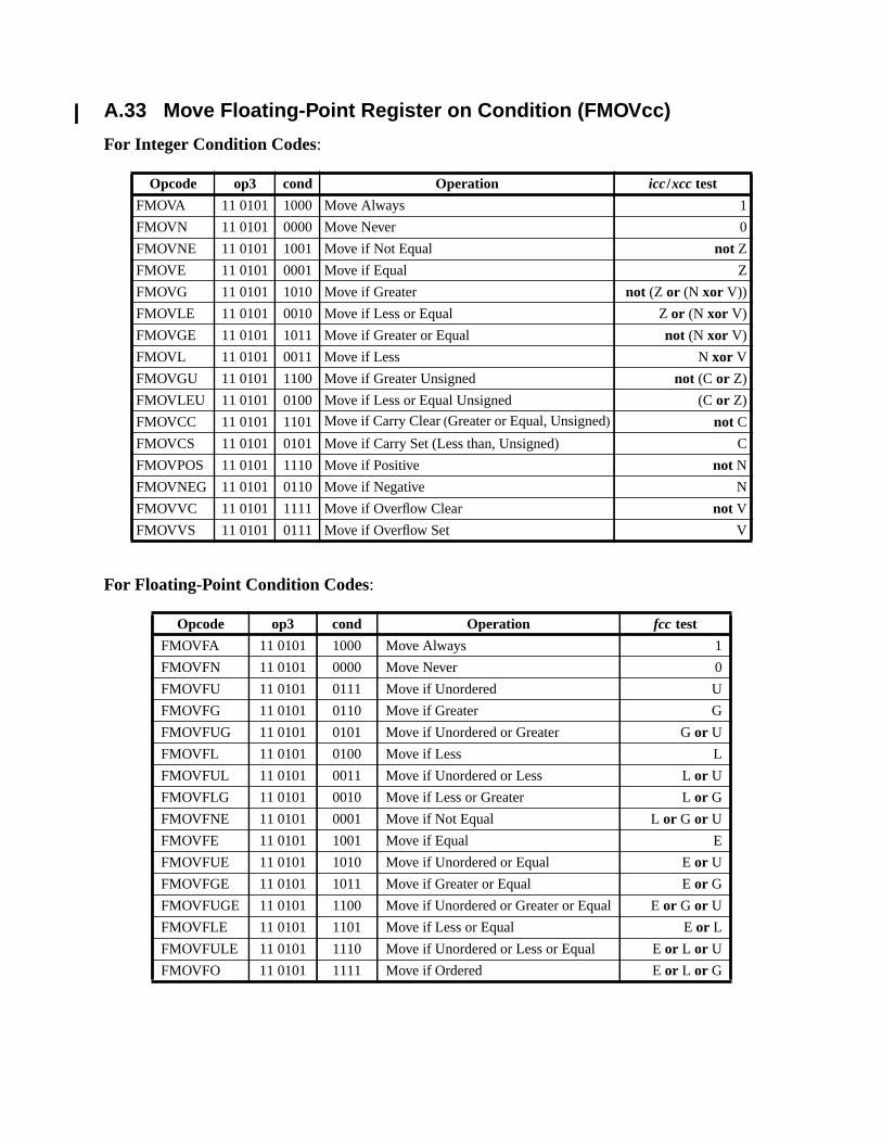
A.33 Move Floating-Point Register on Condition (FMOVcc)
For Integer Condition Codes:
For Floating-Point Condition Codes:
Opcode op3 cond Operation icc/xcc test
FMOVA 11 0101 1000 Move Always 1
FMOVN 11 0101 0000 Move Never 0
FMOVNE 11 0101 1001 Move if Not Equal not Z
FMOVE 11 0101 0001 Move if Equal Z
FMOVG 11 0101 1010 Move if Greater not (Z or (N xor V))
FMOVLE 11 0101 0010 Move if Less or Equal Zor (N xor V)
FMOVGE 11 0101 1011 Move if Greater or Equal not (N xor V)
FMOVL 11 0101 0011 Move if Less N xor V
FMOVGU 11 0101 1100 Move if Greater Unsigned not (C or Z)
FMOVLEU 11 0101 0100 Move if Less or Equal Unsigned (C or Z)
FMOVCC 11 0101 1101 Move if Carry Clear(Greater or Equal, Unsigned) not C
FMOVCS 11 0101 0101 Move if Carry Set (Less than, Unsigned) C
FMOVPOS 11 0101 1110 Move if Positive not N
FMOVNEG 11 0101 0110 Move if Negative N
FMOVVC 11 0101 1111 Move if Overflow Clear not V
FMOVVS 11 0101 0111 Move if Overflow Set V
Opcode op3 cond Operation fcc test
FMOVFA 11 0101 1000 Move Always 1
FMOVFN 11 0101 0000 Move Never 0
FMOVFU 11 0101 0111 Move if Unordered U
FMOVFG 11 0101 0110 Move if Greater G
FMOVFUG 11 0101 0101 Move if Unordered or Greater Gor U
FMOVFL 11 0101 0100 Move if Less L
FMOVFUL 11 0101 0011 Move if Unordered or Less Lor U
FMOVFLG 11 0101 0010 Move if Less or Greater Lor G
FMOVFNE 11 0101 0001 Move if Not Equal Lor G or U
FMOVFE 11 0101 1001 Move if Equal E
FMOVFUE 11 0101 1010 Move if Unordered or Equal Eor U
FMOVFGE 11 0101 1011 Move if Greater or Equal Eor G
FMOVFUGE 11 0101 1100 Move if Unordered or Greater or Equal Eor G or U
FMOVFLE 11 0101 1101 Move if Less or Equal Eor L
FMOVFULE 11 0101 1110 Move if Unordered or Less or Equal Eor L or U
FMOVFO 11 0101 1111 Move if Ordered Eor L or G
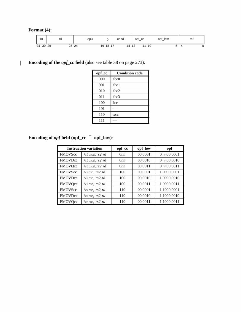
Format (4):
Encoding of the opf_cc field (also see table 38 on page 273):
Encoding of opf field (opf_cc opf_low):
opf_cc Condition code
000 fcc0
001 fcc1
010 fcc2
011 fcc3
100 icc
101 —
110 xcc
111 —
Instruction variation opf_cc opf_low opf
FMOVScc %fcc n,rs2,rd 0nn 00 0001 0nn00 0001
FMOVDcc %fcc n,rs2,rd 0nn 00 0010 0nn00 0010
FMOVQcc %fcc n,rs2,rd 0nn 00 0011 0nn00 0011
FMOVScc %icc , rs2,rd 100 00 0001 1 0000 0001
FMOVDcc %icc , rs2,rd 100 00 0010 1 0000 0010
FMOVQcc %icc , rs2,rd 100 00 0011 1 0000 0011
FMOVScc %xcc, rs2,rd 110 00 0001 1 1000 0001
FMOVDcc %xcc, rs2,rd 110 00 0010 1 1000 0010
FMOVQcc %xcc, rs2,rd 110 00 0011 1 1000 0011
31 1924 18 1314 11 5 4 010172530 29
10 rd op3 cond opf_cc opf_low rs20

For Integer Condition Codes:
Programming Note:To select the appropriate condition code, include “%icc ” or “%xcc” before the registers.
For Floating-Point Condition Codes:
Suggested Assembly Language Syntax
fmov{s,d,q}a i_or_x_cc, fregrs2, fregrd
fmov{s,d,q}n i_or_x_cc, fregrs2, fregrd
fmov{s,d,q}ne i_or_x_cc, fregrs2, fregrd (synonyms: fmov { s,d,q } nz )
fmov{s,d,q}e i_or_x_cc, fregrs2, fregrd (synonyms: fmov { s,d,q } z )
fmov{s,d,q}g i_or_x_cc, fregrs2, fregrd
fmov{s,d,q}le i_or_x_cc, fregrs2, fregrd
fmov{s,d,q}ge i_or_x_cc, fregrs2, fregrd
fmov{s,d,q}l i_or_x_cc, fregrs2, fregrd
fmov{s,d,q}gu i_or_x_cc, fregrs2, fregrd
fmov{s,d,q}leu i_or_x_cc, fregrs2, fregrd
fmov{s,d,q}cc i_or_x_cc, fregrs2, fregrd (synonyms: fmov { s,d,q } geu )
fmov{s,d,q}cs i_or_x_cc, fregrs2, fregrd (synonyms: fmov { s,d,q } lu )
fmov{s,d,q}pos i_or_x_cc, fregrs2, fregrd
fmov{s,d,q}neg i_or_x_cc, fregrs2, fregrd
fmov{s,d,q}vc i_or_x_cc, fregrs2, fregrd
fmov{s,d,q}vs i_or_x_cc, fregrs2, fregrd
Suggested Assembly Language Syntax
fmov{s,d,q}a %fcc n, fregrs2, fregrd
fmov{s,d,q}n %fcc n, fregrs2, fregrd
fmov{s,d,q}u %fcc n, fregrs2, fregrd
fmov{s,d,q}g %fcc n, fregrs2, fregrd
fmov{s,d,q}ug %fcc n, fregrs2, fregrd
fmov{s,d,q}l %fcc n, fregrs2, fregrd
fmov{s,d,q}ul %fcc n, fregrs2, fregrd
fmov{s,d,q}lg %fcc n, fregrs2, fregrd
fmov{s,d,q}ne %fcc n, fregrs2, fregrd (synonyms: fmov { s,d,q } nz )
fmov{s,d,q}e %fcc n, fregrs2, fregrd (synonyms: fmov { s,d,q } z )
fmov{s,d,q}ue %fcc n, fregrs2, fregrd
fmov{s,d,q}ge %fcc n, fregrs2, fregrd
fmov{s,d,q}uge %fcc n, fregrs2, fregrd
fmov{s,d,q}le %fcc n, fregrs2, fregrd
fmov{s,d,q}ule %fcc n, fregrs2, fregrd
fmov{s,d,q}o %fcc n, fregrs2, fregrd

i-
cc andt:
is sug-ance.
Description:
These instructions copy the floating-point register(s) specified byrs2 to the floating-point regis-ter(s) specified byrd if the condition indicated by thecondfield is satisfied by the selected condtion code. The condition code used is specified by theopf_cc field of the instruction. If thecondition is FALSE, then the destination register(s) are not changed.
These instructions do not modify any condition codes.
Programming Note:Branches cause most implementations’ performance to degrade significantly. Frrequently, the MOVFMOVcc instructions can be used to avoid branches. For example, the following C language segmen
double A, B, X;if (A > B) then X = 1.03; else X = 0.0;
can be coded as
! assume A is in %f0; B is in %f2; %xx points to constant arealdd [%xx+C_1.03],%f4 ! X = 1.03fcmpd %fcc3,%f0,%f2 ! A > Bfble ,a %fcc3,label! following only executed if the branch is takenfsubd %f4,%f4,%f4 ! X = 0.0
label:...
This takes four instructions including a branch.
Using FMOVcc, this could be coded as
ldd [%xx+C_1.03],%f4 ! X = 1.03fsubd %f4,%f4,%f6 ! X’ = 0.0fcmpd %fcc3,%f0,%f2 ! A > Bfmovdle %fcc3,%f6,%f4 ! X = 0.0
This also takes four instructions, but requires no branches and may boost performance significantly. Itgested that MOVcc and FMOVcc be used instead of branches wherever they would improve perform
Exceptions:fp_disabledfp_exception_other (invalid_fp_register (quad forms only))fp_exception_other (ftt = unimplemented_FPop (opf_cc= 1012 or 1112)

modify
A.34 Move F-P Register on Integer Register Condition (FMOVr)
Format (4):
Encoding ofopf_low field:
Description:
If the contents of integer registerr[rs1] satisfy the condition specified in thercond field, theseinstructions copy the contents of the floating-point register(s) specified by thers2 field to thefloating-point register(s) specified by therd field. If the contents ofr[rs1] do not satisfy the condi-tion, the floating-point register(s) specified by therd field are not modified.
These instructions treat the integer register contents as a signed integer value; they do notany condition codes.
Opcode op3 rcond Operation Test
— 11 0101 000 Reserved —
FMOVRZ 11 0101 001 Move if Register Zero r[rs1] = 0
FMOVRLEZ 11 0101 010 Move if Register Less Than or Equal to Zero r[rs1] ≤ 0
FMOVRLZ 11 0101 011 Move if Register Less Than Zero r[rs1] < 0
— 11 0101 100 Reserved —
FMOVRNZ 11 0101 101 Move if Register Not Zero r[rs1] ≠ 0
FMOVRGZ 11 0101 110 Move if Register Greater Than Zero r[rs1] > 0
FMOVRGEZ 11 0101 111 Move if Register Greater Than or Equal to Zero r[rs1] ≥ 0
Instruction variation opf_low
FMOVSrcond rs1, rs2, rd 0 0101
FMOVDrcond rs1, rs2, rd 0 0110
FMOVQrcond rs1, rs2, rd 0 0111
Suggested Assembly Language Syntax
fmovr{s,d,q}e regrs1, fregrs2, fregrd (synonym: fmovr{s,d,q}z )
fmovr{s,d,q}lez regrs1, fregrs2, fregrd
fmovr{s,d,q}lz regrs1, fregrs2, fregrd
fmovr{s,d,q}ne regrs1, fregrs2, fregrd (synonym: fmovr{s,d,q}nz )
fmovr{s,d,q}gz regrs1, fregrs2, fregrd
fmovr{s,d,q}gez regrs1, fregrs2, fregrd
31 141924 18 13 12 9 5 4 0102530 29
10 rd op3 0 rcond opf_low rs2rs1

Implementation Note:If this instruction is implemented by tagging each register value with an N (negative) and a Z (zero) bit, usethe following table to determine whetherrcond is TRUE:
Exceptions:fp_disabledfp_exception_other (invalid_fp_register (quad forms only))fp_exception_other (unimplemented_FPop (rcond= 0002 or 1002))
Branch Test
FMOVRNZ not Z
FMOVRZ Z
FMOVGEZ not N
FMOVRLZ N
FMOVRLEZ N or Z
FMOVRGZ N nor Z
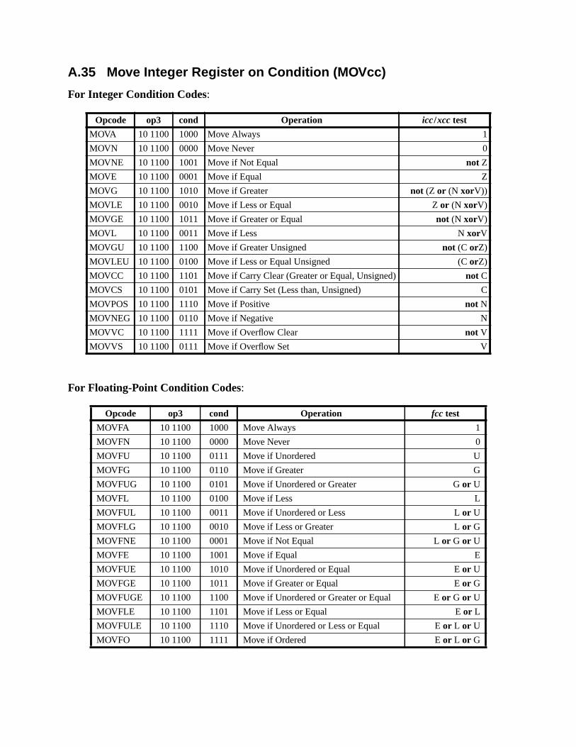
A.35 Move Integer Register on Condition (MOVcc)
For Integer Condition Codes:
For Floating-Point Condition Codes:
Opcode op3 cond Operation icc/xcc test
MOVA 10 1100 1000 Move Always 1
MOVN 10 1100 0000 Move Never 0
MOVNE 10 1100 1001 Move if Not Equal not Z
MOVE 10 1100 0001 Move if Equal Z
MOVG 10 1100 1010 Move if Greater not (Z or (N xorV))
MOVLE 10 1100 0010 Move if Less or Equal Z or (N xorV)
MOVGE 10 1100 1011 Move if Greater or Equal not (N xorV)
MOVL 10 1100 0011 Move if Less N xorV
MOVGU 10 1100 1100 Move if Greater Unsigned not (C orZ)
MOVLEU 10 1100 0100 Move if Less or Equal Unsigned (C orZ)
MOVCC 10 1100 1101 Move if Carry Clear (Greater or Equal, Unsigned) not C
MOVCS 10 1100 0101 Move if Carry Set (Less than, Unsigned) C
MOVPOS 10 1100 1110 Move if Positive not N
MOVNEG 10 1100 0110 Move if Negative N
MOVVC 10 1100 1111 Move if Overflow Clear not V
MOVVS 10 1100 0111 Move if Overflow Set V
Opcode op3 cond Operation fcc test
MOVFA 10 1100 1000 Move Always 1
MOVFN 10 1100 0000 Move Never 0
MOVFU 10 1100 0111 Move if Unordered U
MOVFG 10 1100 0110 Move if Greater G
MOVFUG 10 1100 0101 Move if Unordered or Greater Gor U
MOVFL 10 1100 0100 Move if Less L
MOVFUL 10 1100 0011 Move if Unordered or Less Lor U
MOVFLG 10 1100 0010 Move if Less or Greater Lor G
MOVFNE 10 1100 0001 Move if Not Equal Lor G or U
MOVFE 10 1100 1001 Move if Equal E
MOVFUE 10 1100 1010 Move if Unordered or Equal Eor U
MOVFGE 10 1100 1011 Move if Greater or Equal Eor G
MOVFUGE 10 1100 1100 Move if Unordered or Greater or Equal Eor G or U
MOVFLE 10 1100 1101 Move if Less or Equal Eor L
MOVFULE 10 1100 1110 Move if Unordered or Less or Equal Eor L or U
MOVFO 10 1100 1111 Move if Ordered Eor L or G
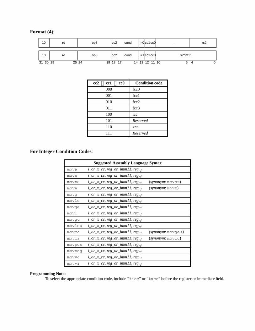
Format (4):
For Integer Condition Codes:
Programming Note:To select the appropriate condition code, include “%icc ” or “%xcc” before the register or immediate field.
cc2 cc1 cc0 Condition code
000 fcc0
001 fcc1
010 fcc2
011 fcc3
100 icc
101 Reserved
110 xcc
111 Reserved
Suggested Assembly Language Syntax
mova i_or_x_cc, reg_or_imm11, regrd
movn i_or_x_cc, reg_or_imm11, regrd
movne i_or_x_cc, reg_or_imm11, regrd (synonym: movnz)
move i_or_x_cc, reg_or_imm11, regrd (synonym: movz)
movg i_or_x_cc, reg_or_imm11, regrd
movle i_or_x_cc, reg_or_imm11, regrd
movge i_or_x_cc, reg_or_imm11, regrd
movl i_or_x_cc, reg_or_imm11, regrd
movgu i_or_x_cc, reg_or_imm11, regrd
movleu i_or_x_cc, reg_or_imm11, regrd
movcc i_or_x_cc, reg_or_imm11, regrd (synonym: movgeu)movcs i_or_x_cc, reg_or_imm11, regrd (synonym: movlu )
movpos i_or_x_cc, reg_or_imm11, regrd
movneg i_or_x_cc, reg_or_imm11, regrd
movvc i_or_x_cc, reg_or_imm11, regrd
movvs i_or_x_cc, reg_or_imm11, regrd
31 24 02530 29 19 18
rd10 op3 —
14 13 12 5 4
cond rs2i=0
rd10 op3 cond simm11i=1
17
cc2
cc2
11
cc1
cc1
10
cc0
cc0
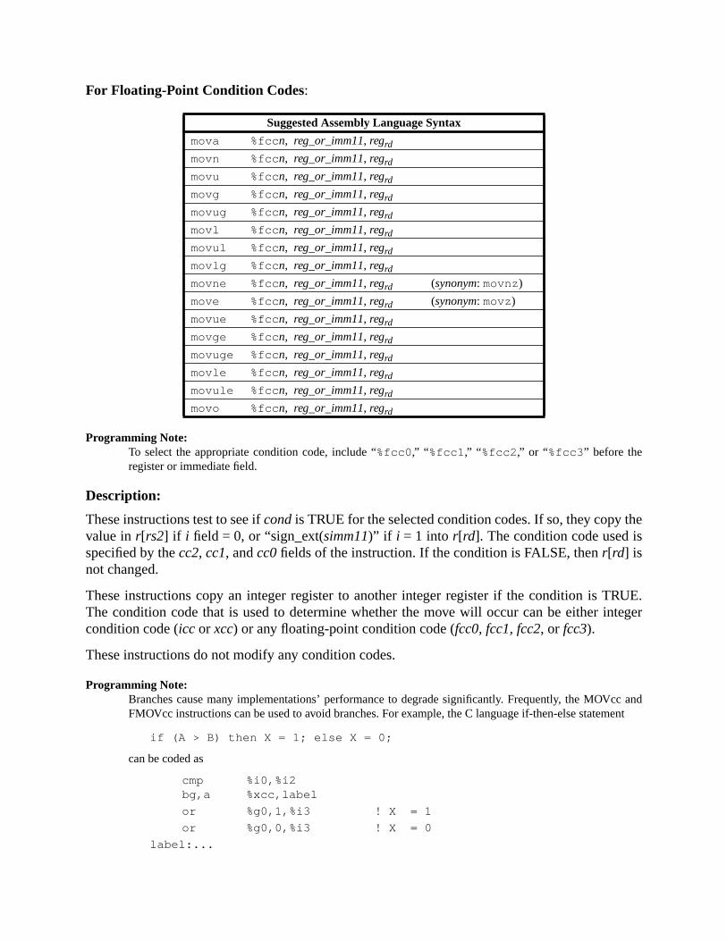
he
RUE.teger
cc andment
For Floating-Point Condition Codes:
Programming Note:To select the appropriate condition code, include “%fcc0 ,” “ %fcc1 ,” “ %fcc2 ,” or “%fcc3 ” before theregister or immediate field.
Description:
These instructions test to see ifcondis TRUE for the selected condition codes. If so, they copy tvalue inr[rs2] if i field = 0, or “sign_ext(simm11)” if i = 1 into r[rd]. The condition code used isspecified by thecc2, cc1, andcc0fields of the instruction. If the condition is FALSE, thenr[rd] isnot changed.
These instructions copy an integer register to another integer register if the condition is TThe condition code that is used to determine whether the move will occur can be either incondition code (icc or xcc) or any floating-point condition code (fcc0, fcc1, fcc2, or fcc3).
These instructions do not modify any condition codes.
Programming Note:Branches cause many implementations’ performance to degrade significantly. Frequently, the MOVFMOVcc instructions can be used to avoid branches. For example, the C language if-then-else state
if (A > B) then X = 1; else X = 0;
can be coded as
cmp %i0,%i2bg,a %xcc,label
or %g0,1,%i3 ! X = 1
or %g0,0,%i3 ! X = 0
label:...
Suggested Assembly Language Syntax
mova %fcc n, reg_or_imm11, regrd
movn %fcc n, reg_or_imm11, regrd
movu %fcc n, reg_or_imm11, regrd
movg %fcc n, reg_or_imm11, regrd
movug %fcc n, reg_or_imm11, regrd
movl %fcc n, reg_or_imm11, regrd
movul %fcc n, reg_or_imm11, regrd
movlg %fcc n, reg_or_imm11, regrd
movne %fcc n, reg_or_imm11, regrd (synonym: movnz)
move %fcc n, reg_or_imm11, regrd (synonym: movz)
movue %fcc n, reg_or_imm11, regrd
movge %fcc n, reg_or_imm11, regrd
movuge %fcc n, reg_or_imm11, regrd
movle %fcc n, reg_or_imm11, regrd
movule %fcc n, reg_or_imm11, regrd
movo %fcc n, reg_or_imm11, regrd
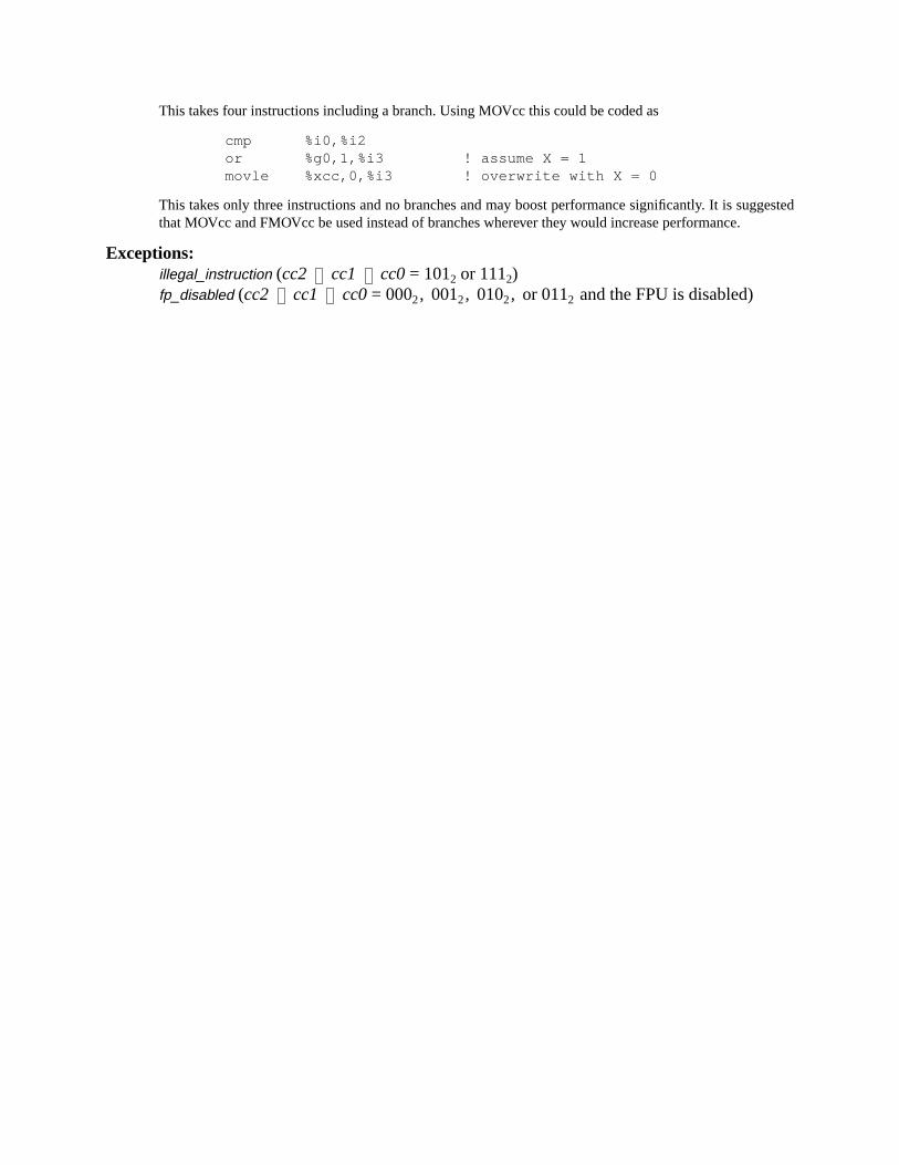
gested
This takes four instructions including a branch. Using MOVcc this could be coded as
cmp %i0,%i2or %g0,1,%i3 ! assume X = 1movle %xcc,0,%i3 ! overwrite with X = 0
This takes only three instructions and no branches and may boost performance significantly. It is sugthat MOVcc and FMOVcc be used instead of branches wherever they would increase performance.
Exceptions:illegal_instruction (cc2 cc1 cc0= 1012 or 1112)fp_disabled (cc2 cc1 cc0= 0002, 0012, 0102, or 0112 and the FPU is disabled)
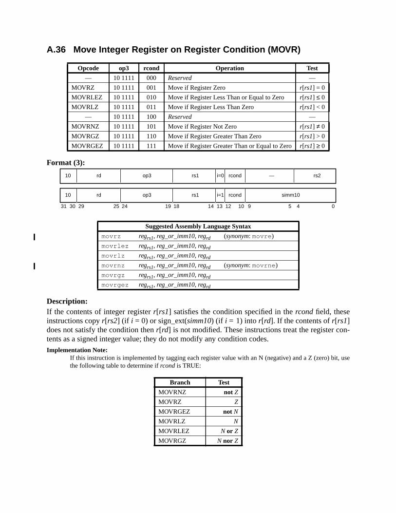
n-
A.36 Move Integer Register on Register Condition (MOVR)
Format (3):
Description:If the contents of integer registerr[rs1] satisfies the condition specified in thercond field, theseinstructions copyr[rs2] (if i = 0) or sign_ext(simm10) (if i = 1) into r[rd]. If the contents ofr[rs1]does not satisfy the condition thenr[rd] is not modified. These instructions treat the register cotents as a signed integer value; they do not modify any condition codes.Implementation Note:
If this instruction is implemented by tagging each register value with an N (negative) and a Z (zero) bit, usethe following table to determine ifrcond is TRUE:
Opcode op3 rcond Operation Test
— 10 1111 000 Reserved —
MOVRZ 10 1111 001 Move if Register Zero r[rs1] = 0
MOVRLEZ 10 1111 010 Move if Register Less Than or Equal to Zero r[rs1] ≤ 0
MOVRLZ 10 1111 011 Move if Register Less Than Zero r[rs1] < 0
— 10 1111 100 Reserved —
MOVRNZ 10 1111 101 Move if Register Not Zero r[rs1] ≠ 0
MOVRGZ 10 1111 110 Move if Register Greater Than Zero r[rs1] > 0
MOVRGEZ 10 1111 111 Move if Register Greater Than or Equal to Zeror[rs1] ≥ 0
Suggested Assembly Language Syntax
movrz regrs1, reg_or_imm10, regrd (synonym: movre )
movrlez regrs1, reg_or_imm10, regrd
movrlz regrs1, reg_or_imm10, regrd
movrnz regrs1, reg_or_imm10, regrd (synonym: movrne )
movrgz regrs1, reg_or_imm10, regrd
movrgez regrs1, reg_or_imm10, regrd
Branch Test
MOVRNZ not Z
MOVRZ Z
MOVRGEZ not N
MOVRLZ N
MOVRLEZ N or Z
MOVRGZ N nor Z
31 24 02530 29 19 18
rd10 op3 —
14 13 12 5 4
rs1 rs2i=0
rd10 op3 rs1 simm10i=1
rcond
rcond
10 9

Exceptions:illegal_instruction (rcond= 0002 or 1002)

or
pro-ers and
nega-
A.37 Multiply and Divide (64-bit)
Format (3):
Description:
MULX computes “r[rs1] × r[rs2]” if i = 0 or “r[rs1] × sign_ext(simm13)” if i = 1, and writes the64-bit product intor[rd]. MULX can be used to calculate the 64-bit product for signedunsigned operands (the product is the same).
SDIVX and UDIVX compute “r[rs1] ÷ r[rs2]” if i = 0 or “r[rs1] ÷ sign_ext(simm13)” if i = 1,and write the 64-bit result intor[rd]. SDIVX operates on the operands as signed integers andduces a corresponding signed result. UDIVX operates on the operands as unsigned integproduces a corresponding unsigned result.
For SDIVX, if the largest negative number is divided by –1, the result should be the largesttive number. That is:
8000 0000 0000 000016 ÷ FFFF FFFF FFFF FFFF16 = 8000 0000 0000 000016.
These instructions do not modify any condition codes.
Exceptions:division_by_zero
Opcode op3 Operation
MULX 00 1001 Multiply (signed or unsigned)
SDIVX 10 1101 Signed Divide
UDIVX 00 1101 Unsigned Divide
Suggested Assembly Language Syntax
mulx regrs1, reg_or_imm, regrdsdivx regrs1, reg_or_imm, regrdudivx regrs1, reg_or_imm, regrd
31 24 02530 29 19 18
rd10 op3 —
14 13 12 5 4
rs1 rs2i=0
rd10 op3 rs1 simm13i=1

hey
s of
om-s on
er
e
A.38 Multiply (32-bit)
Format (3):
Description:
The multiply instructions perform 32-bit by 32-bit multiplications, producing 64-bit results. Tcompute “r[rs1]<31:0>× r[rs2]<31:0>” if i = 0, or “r[rs1]<31:0>× sign_ext(simm13)<31:0>” ifi = 1. They write the 32 most significant bits of the product into the Y register and all 64 bitthe product intor[rd].
Unsigned multiply (UMUL, UMULcc) operates on unsigned integer word operands and cputes an unsigned integer doubleword product. Signed multiply (SMUL, SMULcc) operatesigned integer word operands and computes a signed integer doubleword product.
UMUL and SMUL do not affect the condition code bits. UMULcc and SMULcc write the integcondition code bits,icc andxcc, as follows. Note that 32-bit negative (icc.N) and zero (icc.Z) con-dition codes are set according to thelesssignificant word of the product, and not according to thfull 64-bit result.
Opcode op3 Operation
UMULD 00 1010 Unsigned Integer Multiply
SMULD 00 1011 Signed Integer Multiply
UMULccD 01 1010 Unsigned Integer Multiply and modify cc’s
SMULccD 01 1011 Signed Integer Multiply and modify cc’s
Suggested Assembly Language Syntax
umul regrs1, reg_or_imm, regrd
smul regrs1, reg_or_imm, regrd
umulcc regrs1, reg_or_imm, regrd
smulcc regrs1, reg_or_imm, regrd
The UMUL, UMULcc, SMUL, and SMULcc instructions are deprecated; they areprovided only for compatibility with previous versions of the architecture. Theyshould not be used in new SPARC-V9 software. It is recommended that the MULXinstruction be used in their place.
31 24 02530 29 19 18
rd10 op3 —
14 13 12 5 4
rs1 rs2i=0
rd10 op3 rs1 simm13i=1
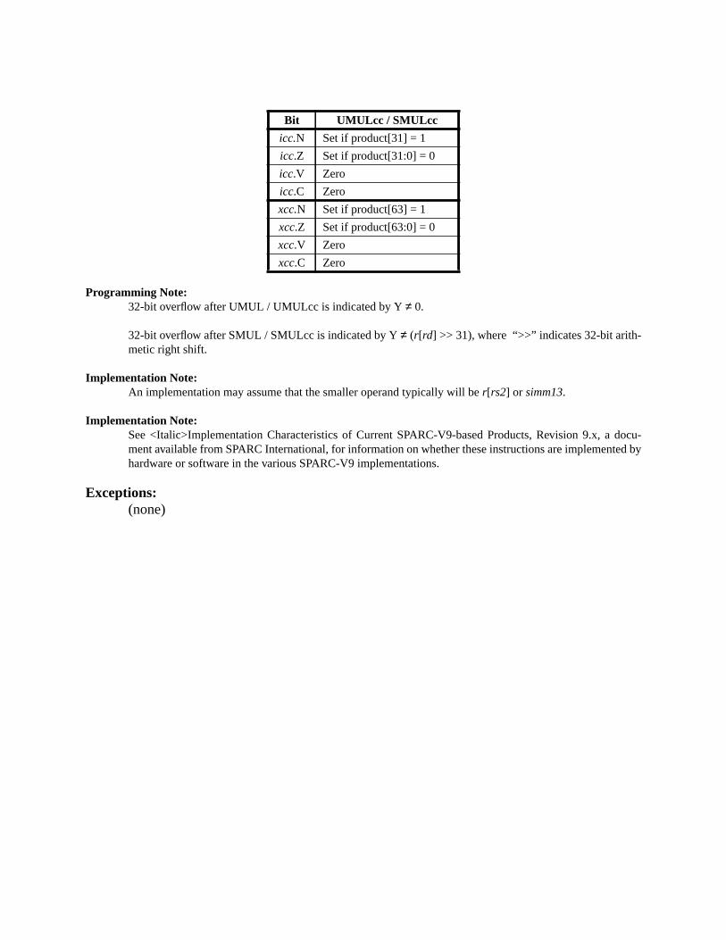
docu-ed by
Programming Note:32-bit overflow after UMUL / UMULcc is indicated by Y≠ 0.
32-bit overflow after SMUL / SMULcc is indicated by Y≠ (r[rd] >> 31), where “>>” indicates 32-bit arith-metic right shift.
Implementation Note:An implementation may assume that the smaller operand typically will ber[rs2] or simm13.
Implementation Note:See <Italic>Implementation Characteristics of Current SPARC-V9-based Products, Revision 9.x, ament available from SPARC International, for information on whether these instructions are implementhardware or software in the various SPARC-V9 implementations.
Exceptions:(none)
Bit UMULcc / SMULcc
icc.N Set if product[31] = 1
icc.Z Set if product[31:0] = 0
icc.V Zero
icc.C Zero
xcc.N Set if product[63] = 1
xcc.Z Set if product[63:0] = 0
xcc.V Zero
xcc.C Zero
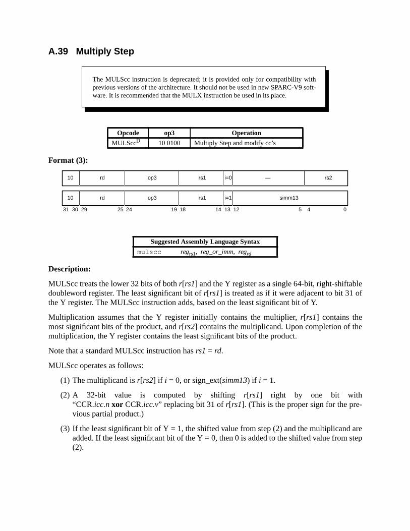
lef
e
-
arestep
A.39 Multiply Step
Format (3):
Description:
MULScc treats the lower 32 bits of bothr[rs1] and the Y register as a single 64-bit, right-shiftabdoubleword register. The least significant bit ofr[rs1] is treated as if it were adjacent to bit 31 othe Y register. The MULScc instruction adds, based on the least significant bit of Y.
Multiplication assumes that the Y register initially contains the multiplier,r[rs1] contains themost significant bits of the product, andr[rs2] contains the multiplicand. Upon completion of thmultiplication, the Y register contains the least significant bits of the product.
Note that a standard MULScc instruction hasrs1 = rd.
MULScc operates as follows:
(1) The multiplicand isr[rs2] if i = 0, or sign_ext(simm13) if i = 1.
(2) A 32-bit value is computed by shiftingr[rs1] right by one bit with“CCR.icc.nxor CCR.icc.v” replacing bit 31 ofr[rs1]. (This is the proper sign for the previous partial product.)
(3) If the least significant bit of Y = 1, the shifted value from step (2) and the multiplicandadded. If the least significant bit of the Y = 0, then 0 is added to the shifted value from(2).
Opcode op3 Operation
MULSccD 10 0100 Multiply Step and modify cc’s
Suggested Assembly Language Syntax
mulscc regrs1, reg_or_imm, regrd
The MULScc instruction is deprecated; it is provided only for compatibility withprevious versions of the architecture. It should not be used in new SPARC-V9 soft-ware. It is recommended that the MULX instruction be used in its place.
31 24 02530 29 19 18
rd10 op3 —
14 13 12 5 4
rs1 rs2i=0
rd10 op3 rs1 simm13i=1
. The
ted
(4) The sum from step (3) is written intor[rd]. The upper 32-bits ofr[rd] are undefined. Theinteger condition codes are updated according to the addition performed in step (3)values of the extended condition codes are undefined.
(5) The Y register is shifted right by one bit, with the least significant bit of the unshifr[rs1] replacing bit 31of Y.
Exceptions:(none)
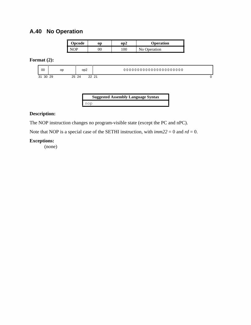
A.40 No Operation
Format (2):
Description:
The NOP instruction changes no program-visible state (except the PC and nPC).
Note that NOP is a special case of the SETHI instruction, withimm22= 0 andrd = 0.
Exceptions:(none)
Opcode op op2 Operation
NOP 00 100 No Operation
Suggested Assembly Language Syntax
nop
31 24 02530 29 22 21
00 op op2 0 0 0 0 0 0 0 0 0 0 0 0 0 0 0 0 0 0 0 0 0 0

-
r this
A.41 Population Count
Format (3):
Description:
POPC counts the number of one bits inr[rs2] if i = 0, or the number of one bits insign_ext(simm13) if i = 1, and stores the count inr[rd]. This instruction does not modify the condition codes.
Implementation Note:Instruction bits 18 through 14 must be zero for POPC. Other encodings of this field (rs1) may be used infuture versions of the SPARC architecture for other instructions.
Programming Note:POPC can be used to “find first bit set” in a register. A C program illustrating how POPC can be used fopurpose follows:
int ffs(zz) /* finds first 1 bit, counting from the LSB */unsigned zz;{
return popc ( zz ^ ( ∼ (–zz))); /* for nonzero zz */}
Inline assembly language code forffs( ) is
neg %IN, %M_IN ! –zz( 2’s complement)xnor %IN, %M_IN, %TEMP ! ^ ∼ –zz (exclusive nor)popc %TEMP,%RESULT ! result = popc( zz ^ ∼ –zz)movrz %IN,%g0,%RESULT ! %RESULT should be 0 for %IN=0
whereIN , M_IN, TEMP, andRESULT are integer registers.
Example:IN = ...00101000! 1st 1 bit from rt is 4th bit–IN = ...11011000∼ –IN = ...00100111IN ^ ∼ –IN = ...00001111popc(IN ^ ∼ –IN) = 4
Exceptions:illegal_instruction (instruction<18:14>≠ 0)
Opcode op3 Operation
POPC 10 1110 Population Count
Suggested Assembly Language Syntax
popc reg_or_imm, regrd
31 24 02530 29 19 18
rd10 op3 —
14 13 12 5 4
0 0000 rs2i=0
rd10 op3 0 0000 simm13i=1

execu-shall
A.42 Prefetch Data
Format (3) PREFETCH:
Format (3) PREFETCHA:
Description:
In nonprivileged code, a prefetch instruction has the same observable effect as a NOP; itstion is nonblocking and cannot cause an observable trap. In particular, a prefetch instructionnot trap if it is applied to an illegal or nonexistent memory address.
IMPL. DEP. #103(1): Whether the execution of a PREFETCH instruction has observable effects in privi-leged code is implementation-dependent.
Opcode op3 Operation
PREFETCH 10 1101 Prefetch Data
PREFETCHAPASI 11 1101 Prefetch Data from Alternate Space
fcn Prefetch function
0 Prefetch for several reads
1 Prefetch for one read
2 Prefetch for several writes
3 Prefetch for one write
4 Prefetch page
5–15 Reserved
16–31 Implementation-dependent
Suggested Assembly Language Syntax
prefetch [address], prefetch_fcn
prefetcha [regaddr] imm_asi, prefetch_fcn
prefetcha [reg_plus_imm] %asi, prefetch_fcn
31 24 02530 29 19 18 14 13 12 5 4
fcn11 op3 rs1 simm13i=1
fcn11 op3 rs1 i=0 — rs2
31 24 02530 29 19 18
fcn11 op3 imm_asi
14 13 12 5 4
rs1 rs2i=0
fcn11 op3 rs1 simm13i=1

l.
efetch-most
ove-pecified
from
ion hass not
dresss
er-
types
r
IMPL. DEP. #103(2): Whether the execution of a PREFETCH instruction can cause adata_access_mmu_miss exception is implementation-dependent.
Whether prefetch always succeeds when theMMU is disabled is implementation-dependent (impdep. # 117).
Implementation Note:Any effects of prefetch in privileged code should be reasonable (e.g., handling ECC errors, no page pring allowed within code that handles page faults). The benefits of prefetching should be available toprivileged code.
Execution of a prefetch instruction initiates data movement (or preparation for future data mment or address mapping) to reduce the latency of subsequent loads and stores to the saddress range.
A successful prefetch initiates movement of a block of data containing the addressed bytememory toward the processor.
IMPL. DEP. #103(3): The size and alignment in memory of the data block is implementation-dependent;the minimum size is 64 bytes and the minimum alignment is a 64-byte boundary.
Programming Note:Software may prefetch 64 bytes beginning at an arbitrary addressaddress by issuing the instructions
prefetch [ address], prefetch_fcn
prefetch [ address + 63], prefetch_fcn
Implementation Note:Prefetching may be used to help manage memory cache(s). A prefetch from a nonprefetchable locatno effect. It is up to memory management hardware to determine how locations are identified aprefetchable.
Prefetch instructions that donot load from an alternate address space access the primary adspace (ASI_PRIMARY{_LITTLE}). Prefetch instructions thatdo load from an alternate addresspace contain the address space identifier (ASI) to be used for the load in theimm_asifield ifi = 0, or in the ASI register ifi = 1. The access is privileged if bit seven of the ASI is zero; othwise, it is not privileged. The effective address for these instructions is “r[rs1] + r[rs2]” if i = 0, or“ r[rs1] + sign_ext(simm13)” if i = 1.
Variants of the prefetch instruction can be used to prepare the memory system for differentof accesses.
IMPL. DEP. #103(4): An implementation may implement none, some, or all of these variants. A variant notimplemented shall execute as a nop. An implemented variant may support its full semantics, or may sup-port just the simple common-case prefetching semantics.
A.42.1 Prefetch Variants
The prefetch variant is selected by thefcnfield of the instruction.fcnvalues 5..15 are reserved fofuture extensions of the architecture.
erentAnof the
ded tople-belowented
cessor,
r hand,
variant
data(read or
riting
e in
IMPL. DEP. #103(5): PREFETCH fcn values of 16..31 are implementation-dependent.
Each prefetch variant reflects an intent on the part of the compiler or programmer. This is difffrom other instructions in SPARC-V9 (except BPN), all of which specify specific actions.implementation may implement a prefetch variant by any technique, as long as the intentvariant is achieved.
The prefetch instruction is designed to treat the common cases well. The variants are intenprovide scalability for future improvements in both hardware and compilers. If a variant is immented, then it should have the effects described below. In case some of the variants listedare implemented and some are not, there is a recommended overloading of the unimplemvariants (see the Implementation Note labeled “Recommended Overloadings” in A.42.2).
A.42.1.1 Prefetch for Several Reads ( fcn = 0)
The intent of this variant is to cause movement of data into the data cache nearest the prowith “reasonable” efforts made to obtain the data.
Implementation Note:If, for example, some TLB misses are handled in hardware, then they should be handled. On the othea multiple ECC error is reasonable cause for cancellation of a prefetch.
This is the most important case of prefetching.
If the addressed data is already present (and owned, if necessary) in the cache, then thishas no effect.
A.42.1.2 Prefetch for One Read ( fcn = 1)
This variant indicates that, if possible, the data cache should be minimally disturbed by theread from the given address, because that data is expected to be read once and not reusedwritten) soon after that.
If the data is already present in the cache, then this variant has no effect.
Programming Note:The intended use of this variant is in streaming large amounts of data into the processor without overwdata in cache memory.
A.42.1.3 Prefetch for Several Writes (and Possibly Reads) ( fcn = 2)
The intent of this variant is to cause movement of data in preparation for writing.
If the addressed data is already present in the data cache, then this variant has no effect.
Programming Note:An example use of this variant is to write a dirty cache line back to memory, or to initialize a cache linpreparation for a partial write.

d, so it
dataafter it
re orat it is
e fault.
has no
s issuedissued.roceed.
e faults.
unim-
d beteger
Implementation Note:On a multiprocessor, this variant indicates that exclusive ownership of the addressed data is needemay have the additional effect of obtaining exclusive ownership of the addressed cache line.
Implementation Note:On a uniprocessor, there is no distinction between Prefetch for Several Reads and this variant.
A.42.1.4 Prefetch for One Write ( fcn = 3)
This variant indicates that, if possible, the data cache should be minimally disturbed by thewritten to this address, because that data is not expected to be reused (read or written) soonhas been written once.
If the data is already present in the cache, then this variant has no effect.
A.42.1.5 Prefetch Page ( fcn = 4)
In a virtual-memory system, the intended action of this variant is for the supervisor softwahardware to initiate asynchronous mapping of the referenced virtual address, assuming thlegal to do so.
Programming Note:The desire is to avoid a later page fault for the given address, or at least to shorten the latency of a pag
In a nonvirtual-memory system, or if the addressed page is already mapped, this varianteffect.
The referenced page need not be mapped when the instruction completes. Loads and storebefore the page is mapped should block just as they would if the prefetch had never beenWhen the activity associated with the mapping has completed, the loads and stores may p
Implementation Note:An example of mapping activity is DMA from secondary storage.
Implementation Note:Use of this variant may be disabled or restricted in privileged code that is not permitted to cause pag
A.42.1.6 Implementation-Dependent Prefetch ( fcn = 16..31)
These values are available for implementations to use. An implementation shall treat anyplemented prefetchfcn values as NOPs (impl. dep. #103).
A.42.2 General Comments
There is no variant of PREFETCH for instruction prefetching. Instruction prefetching shoulencoded using the Branch Never (BPN) form of the BPcc instruction (see A.7, “Branch on InCondition Codes with Prediction (BPcc)”).

exe-ost ofsignifi-
nts,
e effi-
Severalch foror Sev-
riants
che,” solarge
small,
One error to avoid in thinking about prefetch instructions is that they should have “no cost tocute.” As long as the cost of executing a prefetch instruction is well less than one-third the ca cache miss, use of prefetching is a net win. It does not appear that prefetching causes acant number of useless fetches from memory, though it may increase the rate ofuseful fetches(and hence the bandwidth), because it more efficiently overlaps computing with fetching.
Implementation Note:Recommended Overloadings.There are four recommended sets of overloadings for the prefetch variabased on a simplistic classification of SPARC-V9 systems into cost (low-costvs. high-cost) and processormultiplicity (uniprocessorvs. multiprocessor) categories. These overloadings are chosen to help ensurcient portability of software across a range of implementations.
In a uniprocessor, there is no need to support multiprocessor cache protocols; hence, Prefetch forReads and Prefetch for Several Writes may behave identically. In a low-cost implementation, PrefetOne Read and Prefetch for One Write may be identical to Prefetch for Several Reads and Prefetch feral Writes, respectively.
Programming Note:A SPARC-V9 compiler that generates PREFETCH instructions should generate each of the four vawhere it is most appropriate. The overloadings suggested in the previousImplementation NoteNOTEensurethat such code will be portable and reasonably efficient across a range of hardware configurations.
Implementation Note:The Prefetch for One Read and Prefetch for One Write variants assume the existence of a “bypass cathat the bulk of the “real cache” remains undisturbed. If such a bypass cache is used, it should beenough to properly shield the processor from memory latency. Such a cache should probably behighly associative, and use a FIFO replacement policy.
Exceptions:
Multiplicity Cost Prefetch for ..
Could be overloadedto mean the same as
Prefetch for ..
Uniprocessor Low
One read Several writes
Several reads Several writes
One write Several writes
Several writes —
Uniprocessor High
One read —
Several reads Several writes
One write —
Several writes —
Multiprocessor Low
One read Several reads
Several reads —
One write Several writes
Several writes —
Multiprocessor High
One read —
Several reads —
One write —
Several writes —
data_access_MMU_miss (implementation-dependent (impl. dep. #103))illegal_instruction (fcn=5..15)
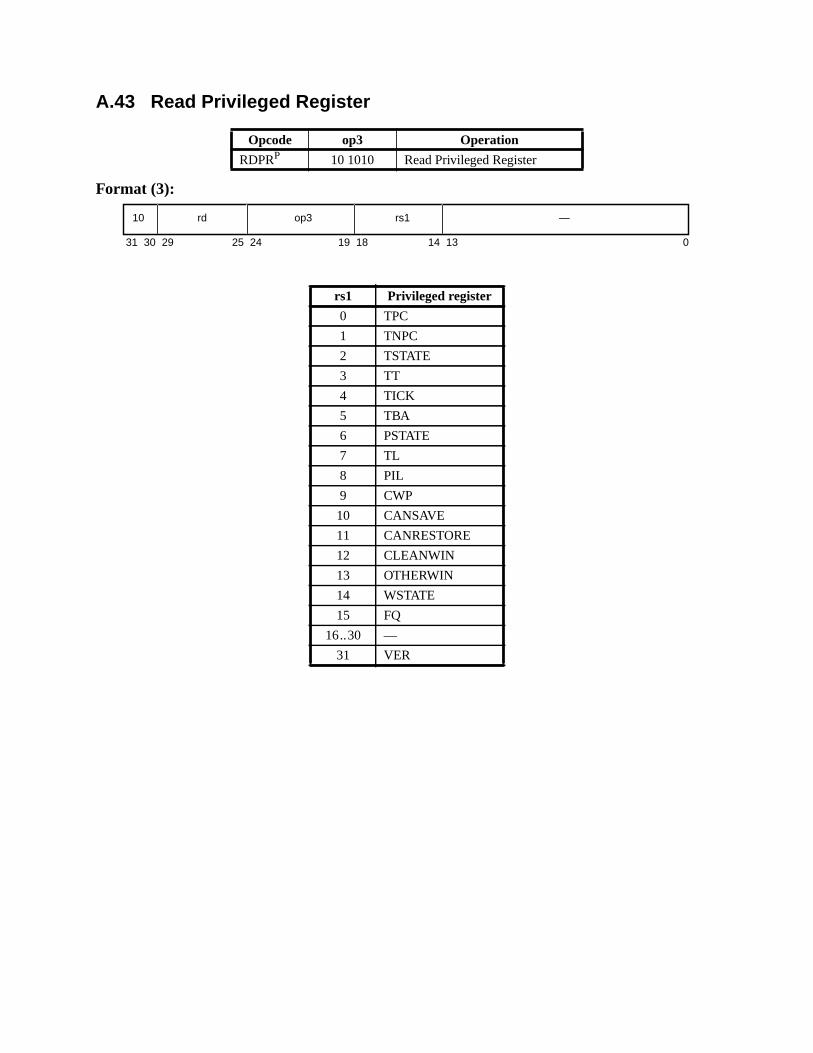
A.43 Read Privileged Register
Format (3):
Opcode op3 Operation
RDPRP 10 1010 Read Privileged Register
rs1 Privileged register
0 TPC
1 TNPC
2 TSTATE
3 TT
4 TICK
5 TBA
6 PSTATE
7 TL
8 PIL
9 CWP
10 CANSAVE
11 CANRESTORE
12 CLEANWIN
13 OTHERWIN
14 WSTATE
15 FQ
16..30 —
31 VER
31 141924 18 13 02530 29
10 rd op3 rs1 —
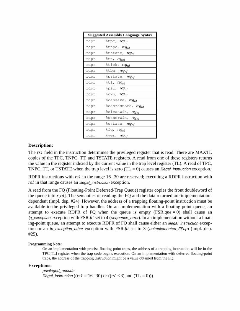
XTLturns
TPC,
ith
rd oftion-
ust bee, an
n thepoint
Description:
The rs1 field in the instruction determines the privileged register that is read. There are MAcopies of the TPC, TNPC, TT, and TSTATE registers. A read from one of these registers rethe value in the register indexed by the current value in the trap level register (TL). A read ofTNPC, TT, or TSTATE when the trap level is zero (TL = 0) causes anillegal_instruction exception.
RDPR instructions withrs1 in the range 16..30 are reserved; executing a RDPR instruction wrs1 in that range causes anillegal_instruction exception.
A read from the FQ (Floating-Point Deferred-Trap Queue) register copies the front doublewothe queue intor[rd]. The semantics of reading the FQ and the data returned are implementadependent (impl. dep. #24). However, the address of a trapping floating-point instruction mavailable to the privileged trap handler. On an implementation with a floating-point queuattempt to execute RDPR of FQ when the queue is empty (FSR.qne= 0) shall cause anfp_exception exception with FSR.ftt set to 4 (sequence_error). In an implementation without a float-ing-point queue, an attempt to execute RDPR of FQ shall cause either anillegal_instruction excep-tion or an fp_exception_other exception with FSR.ftt set to 3 (unimplemented_FPop) (impl. dep.#25).
Programming Note:On an implementation with precise floating-point traps, the address of a trapping instruction will be iTPC[TL] register when the trap code begins execution. On an implementation with deferred floating-traps, the address of the trapping instruction might be a value obtained from the FQ.
Exceptions:privileged_opcodeillegal_instruction ((rs1 = 16..30) or ((rs1≤3) and (TL = 0)))
Suggested Assembly Language Syntax
rdpr %tpc, regrd
rdpr %tnpc, regrd
rdpr %tstate, regrd
rdpr %tt, regrd
rdpr %tick, regrd
rdpr %tba, regrd
rdpr %pstate, regrd
rdpr %tl, regrd
rdpr %pil, regrd
rdpr %cwp, regrd
rdpr %cansave, regrd
rdpr %canrestore, regrd
rdpr %cleanwin, regrd
rdpr %otherwin, regrd
rdpr %wstate, regrd
rdpr %fq, regrd
rdpr %ver, regrd

fp_exception_other (sequence_error) (RDPR of FQ when FSR.qne= 0 in a system with anFQ; (impl. dep. #25)
illegal_instruction (RDPR of FQ in a system without an FQ; (impl. dep. #25)

hed
eto use
A.44 Read State Register
Format (3):
Description:
These instructions read the specified state register intor[rd].
Note that RDY, RDCCR, RDASI, RDPC, RDTICK, RDFPRS, and RDASR are distinguisonly by the value in thers1 field.
If rs1≥ 7, an ancillary state register is read. Values ofrs1 in the range 7..14 are reserved for futurversions of the architecture; values in the range 16..31 are available for implementations(impl. dep. #8). A RDASR instruction withrs1 = 15, rd = 0, andi = 0 is defined to be an STBARinstruction (see A.51). An RDASR instruction withrs1 = 15, rd = 0, andi = 1 is defined to be a
Opcode op3 rs1 Operation
RDYD 10 1000 0 Read Y Register
— 10 1000 1 reserved
RDCCR 10 1000 2 Read Condition Codes Register
RDASI 10 1000 3 Read ASI Register
RDTICKPNPT 10 1000 4 Read Tick Register
RDPC 10 1000 5 Read Program Counter
RDFPRS 10 1000 6 Read Floating-Point Registers Status Register
RDASRPASR 10 1000 7−14 Read Ancillary State Register (reserved)
See text 10 1000 15 See text
RDASRPASR 10 1000 16−31 Implementation-dependent (impl. dep. #47)
Suggested Assembly Language Syntax
rd %y, regrd
rd %ccr , regrd
rd %asi , regrd
rd %tick , regrd
rd %pc , regrd
rd %fprs , regrd
rd asr_regrs1, regrd
The RDY instruction is deprecated; it is provided only for compatibility with previ-ous versions of the architecture. It should not be used in new SPARC-V9 software.It is recommended that all instructions which reference the Y register be avoided.
31 141924 18 13 02530 29
10 rd op3 rs1 —
12
i=0

t
efore
the
l reg-9.x, ars.
SR,
xten-
MEMBAR instruction (see A.32). RDASR withrs1 = 15 andrd≠0 is reserved for future versionsof the architecture; it causes anillegal_instruction exception.
RDTICK causes aprivileged_action exception if PSTATE.PRIV = 0 and TICK.NPT = 1.
For RDPC, the high-order 32-bits of the PC value stored inr[rd] are implementation-dependenwhen PSTATE.AM = 1 (impl. dep. #125).
RDFPRS waits for all pending FPops and loads of floating-point registers to complete breading the FPRS register.
IMPL. DEP. #47: RDASR instructions with rd in the range 16..31 are available for implementation-depen-dent uses (impl. dep. #8). For a RDASR instruction with rs1 in the range 16 .. 31, the following are imple-mentation-dependent: the interpretation of bits 13:0 and 29:25 in the instruction, whether the instruction isprivileged (impl. dep. #9), and whether the instruction causes an illegal_instruction exception.
See I.1.1, “Read/Write Ancillary State Registers (ASRs),” for a discussion of extendingSPARC-V9 instruction set using read/write ASR instructions.
Implementation Note:Ancillary state registers may include (for example) timer, counter, diagnostic, self-test, and trap-controisters. See <Italic>Implementation Characteristics of Current SPARC-V9-based Products, Revisiondocument available from SPARC International, for information on implemented ancillary state registe
Compatibility Note:The SPARC-V8 RDPSR, RDWIM, and RDTBR instructions do not exist in SPARC-V9 since the PWIM, and TBR registers do not exist in SPARC-V9.
Exceptions:privileged_opcode (RDASR only; implementation-dependent (impl. dep. #47))illegal_instruction (RDASR withrs1 = 1 or 7..14; RDASR withrs1 = 15 andrd≠0; RDASR
with rs1 = 16..31 and the implementation does not define the instruction as an esion; implementation-dependent (impl. dep. #47))
privileged_action (RDTICK only)

as theo the
tion in
A.45 RETURN
Format (3):
Description:
The RETURN instruction causes a delayed transfer of control to the target address and hwindow semantics of a RESTORE instruction; that is, it restores the register window prior tlast SAVE instruction. The target address is “r[rs1] + r[rs2]” if i = 0, or“ r[rs1] + sign_ext(simm13)” if i = 1. Registersr[rs1] andr[rs2] come from theold window.
The RETURN instruction may cause an exception. It may cause awindow_fill exception as part ofits RESTORE semantics or it may cause amem_address_not_aligned exception if either of the twolow-order bits of the target address are nonzero.
Programming Note:To reexecute the trapped instruction when returning from a user trap handler, use the RETURN instructhe delay slot of a JMPL instruction, for example:
jmpl %l6,%g0 ! Trapped PC supplied to user trap handlerreturn %l7 ! Trapped nPC supplied to user trap handler
Programming Note:A routine that uses a register window may be structured either as
save %sp,- framesize, %sp. . .ret ! Same as jmpl %i7 + 8, %g0restore ! Something useful like “restore %o2,%l2,%o0”
or as
save %sp,- framesize, %sp. . .return %i7 + 8nop ! Could do some useful work in the caller’s
! window e.g. “or %o1, %o2,%o0”
Exceptions:mem_address_not_alignedfill_n_normal (n = 0..7)
Opcode op3 Operation
RETURN 11 1001 RETURN
Suggested Assembly Language Syntax
return address
31 24 02530 29 19 18
—10 op3 —
14 13 12 5 4
rs1 rs2i=0
10 op3 rs1 simm13i=1—

fill_n_other (n = 0..7)

; that
exe-
like
ruc-ctionWP.
soft-
toring
A.46 SAVE and RESTORE
Format (3):
Description (Effect on Nonprivileged State):
The SAVE instruction provides the routine executing it with a new register window. Theout regis-ters from the old window become thein registers of the new window. The contents of theout andthe local registers in the new window are zero or contain values from the executing processis, the process sees a clean window.
The RESTORE instruction restores the register window saved by the last SAVE instructioncuted by the current process. Thein registers of the old window become theout registers of thenew window. Thein andlocal registers in the new window contain the previous values.
Furthermore, if and only if a spill or fill trap is not generated, SAVE and RESTORE behavenormal ADD instructions, except that the source operandsr[rs1] and/orr[rs2] are read from theold window (that is, the window addressed by the original CWP) and the sum is written intor[rd]of thenew window (that is, the window addressed by the new CWP).
Note that CWP arithmetic is performed modulo the number of implemented windows,NWIN-DOWS.
Programming Note:Typically, if a SAVE (RESTORE) instruction traps, the spill (fill) trap handler returns to the trapped insttion to reexecute it. So, although the ADD operation is not performed the first time (when the instrutraps), it is performed the second time the instruction executes. The same applies to changing the C
Programming Note:The SAVE instruction can be used to atomically allocate a new window in the register file and a newware stack frame in memory. See H.1.2, “Leaf-Procedure Optimization,” for details.
Programming Note:There is a performance tradeoff to consider between using SAVE/RESTORE and saving and resselected registers explicitly.
Opcode op3 Operation
SAVE 11 1100 Save caller’s window
RESTORE 11 1101 Restore caller’s window
Suggested Assembly Language Syntax
save regrs1, reg_or_imm, regrd
restore regrs1, reg_or_imm, regrd
31 24 02530 29 19 18
rd10 op3 —
14 13 12 5 4
rs1 rs2i=0
10 op3 rs1 simm13i=1rd
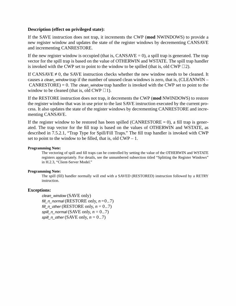
SAVE
trapdler
d. It–
e
t pro-incre-
ner-, asP
ATEdows”
Y
Description (effect on privileged state):
If the SAVE instruction does not trap, it increments the CWP (mod NWINDOWS) to provide anew register window and updates the state of the register windows by decrementing CANand incrementing CANRESTORE.
If the new register window is occupied (that is, CANSAVE = 0), a spill trap is generated. Thevector for the spill trap is based on the value of OTHERWIN and WSTATE. The spill trap hanis invoked with the CWP set to point to the window to be spilled (that is, old CWP+ 2).
If CANSAVE ≠ 0, the SAVE instruction checks whether the new window needs to be cleanecauses aclean_window trap if the number of unused clean windows is zero, that is, (CLEANWINCANRESTORE) = 0. Theclean_window trap handler is invoked with the CWP set to point to thwindow to be cleaned (that is, old CWP+ 1).
If the RESTORE instruction does not trap, it decrements the CWP (mod NWINDOWS) to restorethe register window that was in use prior to the last SAVE instruction executed by the currencess. It also updates the state of the register windows by decrementing CANRESTORE andmenting CANSAVE.
If the register window to be restored has been spilled (CANRESTORE = 0), a fill trap is geated. The trap vector for the fill trap is based on the values of OTHERWIN and WSTATEdescribed in 7.5.2.1, “Trap Type for Spill/Fill Traps.” The fill trap handler is invoked with CWset to point to the window to be filled, that is, old CWP – 1.
Programming Note:The vectoring of spill and fill traps can be controlled by setting the value of the OTHERWIN and WSTregisters appropriately. For details, see the unnumbered subsection titled “Splitting the Register Winin H.2.3, “Client-Server Model.”
Programming Note:The spill (fill) handler normally will end with a SAVED (RESTORED) instruction followed by a RETRinstruction.
Exceptions:clean_window (SAVE only)fill_n_normal (RESTORE only,n=0..7)fill_n_other (RESTORE only,n = 0..7)spill_n_normal (SAVE only,n = 0..7)spill_n_other (SAVE only,n = 0..7)
illed
0).
ateonsis-
A.47 SAVED and RESTORED
Format (3):
Description:
SAVED and RESTORED adjust the state of the register-windows control registers.
SAVED increments CANSAVE. If OTHERWIN = 0, it decrements CANRESTORE.If OTHERWIN≠0, it decrements OTHERWIN.
RESTORED increments CANRESTORE. If CLEANWIN< (NWINDOWS-1), RESTOREDincrements CLEANWIN. If OTHERWIN = 0, it decrements CANSAVE.If OTHERWIN ≠ 0, it decrements OTHERWIN.
Programming Note:The spill (fill) handlers use the SAVED (RESTORED) instruction to indicate that a window has been sp(filled) successfully. See H.2.2, “Example Code for Spill Handler,” for details.
Programming Note:Normal privileged software would probably not do a SAVED or RESTORED from trap level zero (TL =However, it is not illegal to do so, and does not cause a trap.
Programming Note:Executing a SAVED (RESTORED) instruction outside of a window spill (fill) trap handler is likely to crean inconsistent window state. Hardware will not signal an exception, however, since maintaining a ctent window state is the responsibility of privileged software.
Exceptions:privileged_opcodeillegal_instruction (fcn=2..31)
Opcode op3 fcn Operation
SAVEDP 11 0001 0 Window has been Saved
RESTOREDP 11 0001 1 Window has been Restored
— 11 0001 2..31 Reserved
Suggested Assembly Language Syntax
saved
restored
31 1924 18 02530 29
10 fcn op3 —

s
ss than
he neg-
A.48 SETHI
Format (2):
Description:
SETHI zeroes the least significant 10 bits and the most significant 32 bits ofr[rd], and replacesbits 31 through 10 ofr[rd] with the value from itsimm22 field.
SETHI does not affect the condition codes.
A SETHI instruction withrd = 0 and imm22= 0 is defined to be a NOP instruction, which idefined in A.40.
Programming Note:The most common form of 64-bit constant generation is creating stack offsets whose magnitude is le232. The code below can be used to create the constant 0000 0000 ABCD 123416:
sethi %hi(0xabcd1234),%o0or %o0, 0x234, %o0
The following code shows how to create a negative constant. Note that the immediate field of thexorinstruction is sign extended and can be used to get 1s in all of the upper 32 bits. For example, to set tative constant FFFF FFFF ABCD 123416:
sethi %hi(0x5432edcb),%o0! note 0x5432EDCB, not 0xABCD1234xor %o0, 0x1e34, %o0 ! part of imm. overlaps upper bits
Exceptions:(none)
Opcode op op2 Operation
SETHI 00 100 Set High 22 Bits of Low Word
Suggested Assembly Language Syntax
sethi const22, regrd
sethi %hi (value), regrd
31 2224 21 02530 29
00 rd 100 imm22

A.49 Shift
Format (3):
Description:
When i = 0 andx = 0, the shift count is the least significant five bits ofr[rs2]. When i = 0 andx = 1, the shift count is the least significant six bits ofr[rs2]. Wheni = 1 andx = 0, the shift countis the immediate value specified in bits 0 through 4 of the instruction. Wheni = 1 andx = 1, theshift count is the immediate value specified in bits 0 through 5 of the instruction.
SLL and SLLX shift all 64 bits of the value inr[rs1] left by the number of bits specified by theshift count, replacing the vacated positions with zeroes, and write the shifted result tor[rd].
Opcode op3 x Operation
SLL 10 0101 0 Shift Left Logical - 32 Bits
SRL 10 0110 0 Shift Right Logical - 32 Bits
SRA 10 0111 0 Shift Right Arithmetic - 32 Bits
SLLX 10 0101 1 Shift Left Logical - 64 Bits
SRLX 10 0110 1 Shift Right Logical - 64 Bits
SRAX 10 0111 1 Shift Right Arithmetic - 64 Bits
Suggested Assembly Language Syntax
sll regrs1, reg_or_shcnt, regrd
srl regrs1, reg_or_shcnt, regrd
sra regrs1, reg_or_shcnt, regrd
sllx regrs1, reg_or_shcnt, regrd
srlx regrs1, reg_or_shcnt, regrd
srax regrs1, reg_or_shcnt, regrd
i x Shift count
0 0 bits 4 .. 0 ofr[rs2]
0 1 bits 5 .. 0 ofr[rs2]
1 0 bits 4..0 of instruction
1 1 bits 5..0 of instruction
31 24 02530 29 19 18
rd10 op3 —
14 13 12 5 4
rs1 rs2i=0 x
rd10 op3 —rs1 shcnt32i=1 x=0
rd10 op3 —rs1 shcnt64i=1 x=1
6
fttten to
ftritten
ftt
ft
2-bit
nto
SRL shifts the low 32 bits of the value inr[rs1] right by the number of bits specified by the shicount. Zeroes are shifted into bit 31. The upper 32 bits are set to zero, and the result is wrir[rd].
SRLX shifts all 64 bits of the value inr[rs1] right by the number of bits specified by the shicount. Zeroes are shifted into the vacated high-order bit positions, and the shifted result is wto r[rd].
SRA shifts the low 32 bits of the value inr[rs1] right by the number of bits specified by the shicount, and replaces the vacated positions with bit 31 ofr[rs1]. The high order 32 bits of the resulare all set with bit 31 ofr[rs1], and the result is written tor[rd].
SRAX shifts all 64 bits of the value inr[rs1] right by the number of bits specified by the shicount, and replaces the vacated positions with bit 63 ofr[rs1]. The shifted result is written tor[rd].
No shift occurs when the shift count is zero, but the high-order bits are affected by the 3shifts as noted above.
These instructions do not modify the condition codes.
Programming Note:“Arithmetic left shift by 1 (and calculate overflow)” can be effected with the ADDcc instruction.
Programming Note:The instruction “sra rs1,0, rd” can be used to convert a 32-bit value to 64 bits, with sign extension ithe upper word. “srl rs1,0, rd” can be used to clear the upper 32 bits ofr[rd].
Exceptions:(none)

ed oreset
g.
s exe-tware-bout
e is
A.50 Software-Initiated Reset
Format (3):
Description:
SIR is used to generate a software-initiated reset (SIR). It may be executed in either privilegnonprivileged mode, with slightly different effect. As with other traps, a software-initiated rperforms different actions when TL = MAXTL than it does when TL< MAXTL.
When executed in user mode, the action of SIR is conditional on the SIR_enable control fla
IMPL. DEP. #116: The location of the SIR_enable control flag and the means of accessing the SIR_enablecontrol flag are implementation-dependent. In some implementations it may be permanently zero.
When SIR_enable is 0, SIR executes without effect (as a NOP) in user mode. When SIR icuted in privileged mode or in user mode with SIR_enable = 1, the processor performs a sofinitiated reset. See 7.6.2.5, “Software-Initiated Reset (SIR) Traps,” for more information asoftware-initiated resets.
Programming Note:This instruction is never illegal. It is not a privileged instruction, even though its action in privileged moddifferent than in user mode.
Exceptions:software_initiated_reset
Opcode op3 rd Operation
SIR 11 0000 15 Software-initiated reset
Suggested Assembly Language Syntax
sir simm13
31 1924 18 02530 29
10 0 1111 op3
14 13
0 0000 simm13
12
i=1

by
emory.
that
mory
rationsmory byllowedd not to
sors.
A.51 Store Barrier
Format (3):
Description:
The store barrier instruction (STBAR) forcesall store and atomic load-store operations issueda processor prior to the STBAR to complete their effects on memory beforeany store or atomicload-store operations issued by that processor subsequent to the STBAR are executed by m
Note that the encoding of STBAR is identical to that of the RDASR instruction exceptrs1 = 15 andrd = 0, and is identical to that of the MEMBAR instruction except that bit 13 (i) = 0.
The coherence and atomicity of memory operations between processors and I/O DMA meaccesses are implementation-dependent (impl. dep #120).
Compatibility Note:STBAR is identical in function to a MEMBAR instruction withmmask= 816. STBAR is retained for com-patibility with SPARC-V8.
Implementation Note:For correctness, it is sufficient for a processor to stop issuing new store and atomic load-store opewhen an STBAR is encountered and resume after all stores have completed and are observed in meall processors. More efficient implementations may take advantage of the fact that the processor is ato issue store and load-store operations after the STBAR, as long as those operations are guaranteebecome visible before all the earlier stores and atomic load-stores have become visible to all proces
Exceptions:(none)
Opcode op3 Operation
STBARD 10 1000 Store Barrier
Suggested Assembly Language Syntax
stbar
The STBAR instruction is deprecated; it is provided only for compatibility withprevious versions of the architecture. It should not be used in new SPARC-V9 soft-ware. It is recommended that the MEMBAR instruction be used in its place.
31 141924 18 13 02530 29
10 0 op3 0 1111 —
12
0

ting-
t reg-
uting
ting
A.52 Store Floating-Point
† Encoded floating-point register value, as described in 5.1.4.1
Format (3):
Description:
The store single floating-point instruction (STF) copiesf [rd] into memory.
The store double floating-point instruction (STDF) copies a doubleword from a double floapoint register into a word-aligned doubleword in memory.
The store quad floating-point instruction (STQF) copies the contents of a quad floating-poinister into a word-aligned quadword in memory.
The store floating-point state register lower instruction (STFSR) waits for any currently execFPop instructions to complete, and then writes the lower 32 bits of the FSR into memory.
The store floating-point state register instruction (STXFSR) waits for any currently execuFPop instructions to complete, and then writes all 64 bits of the FSR into memory.
Opcode op3 rd Operation
STF 10 0100 0..31 Store Floating-Point Register
STDF 10 0111 † Store Double Floating-Point Register
STQF 10 0110 † Store Quad Floating-Point Register
STFSRD 10 0101 0 Store Floating-Point State Register Lower
STXFSR 10 0101 1 Store Floating-Point State Register
— 10 0101 2..31 Reserved
Suggested Assembly Language Syntax
st freg rd , [address]
std freg rd , [address]
stq freg rd , [address]
st %fsr , [address]
stx %fsr , [address]
The STFSR instruction is deprecated; it is provided only for compatibility with pre-vious versions of the architecture. It should not be used in new SPARC-V9 soft-ware. It is recommended that the STXFSR instruction be used in its place.
31 24 02530 29 19 18 14 13 12 5 4
rd11 op3 rs1 simm13i=1
rd11 op3 rs1 i=0 — rs2

storeFSR.
gistertruc-
e thatstoresen they
Compatibility Note:SPARC-V9 needs two store-FSR instructions, since the SPARC-V8 STFSR instruction is defined toonly 32 bits of the FSR into memory. STXFSR allows SPARC-V9 programs to store all 64 bits of the
STFSR and STXFSR zero FSR.ftt after writing the FSR to memory.
Implementation Note:FSR.ftt should not be zeroed until it is known that the store will not cause a precise trap.
The effective address for these instructions is “r[rs1] + r[rs2]” if i = 0, or“ r[rs1] + sign_ext(simm13)” if i = 1.
STF, STFSR, STDF, and STQF cause amem_address_not_aligned exception if the effective mem-ory address is not word-aligned; STXFSR causes amem_address_not_aligned exception if theaddress is not doubleword-aligned. If the floating-point unit is not enabled for the source rerd (per FPRS.FEF and PSTATE.PEF), or if the FPU is not present, a store floating-point instion causes anfp_disabled exception.
IMPL. DEP. #110(1): STDF requires only word alignment in memory. If the effective address is word-aligned but not doubleword-aligned, it may cause an STDF_mem_address_not_aligned exception. In thiscase the trap handler software shall emulate the STDF instruction and return.
IMPL. DEP. #112(1): STQF requires only word alignment in memory. If the effective address is word-aligned but not quadword-aligned, it may cause an STQF_mem_address_not_aligned exception. In thiscase the trap handler software shall emulate the STQF instruction and return.
Programming Note:In SPARC-V8, some compilers issued sets of single-precision stores when they could not determindouble- or quadword operands were properly aligned. For SPARC-V9, since emulation of misalignedis expected to be fast, it is recommended that compilers issue sets of single-precision stores only whcan determine that double- or quadword operands arenot properly aligned.
Exceptions:async_data_errorfp_disabledmem_address_not_alignedSTDF_mem_address_not_aligned (STDF only) (impl. dep. #110)STQF_mem_address_not_aligned (STQF only) (impl. dep. #112)data_access_exceptiondata_access_protectiondata_access_MMU_missdata_access_errorillegal_instruction (op3= 2516 andrd = 2..31)fp_exception_other (invalid_fp_register (STQF only))
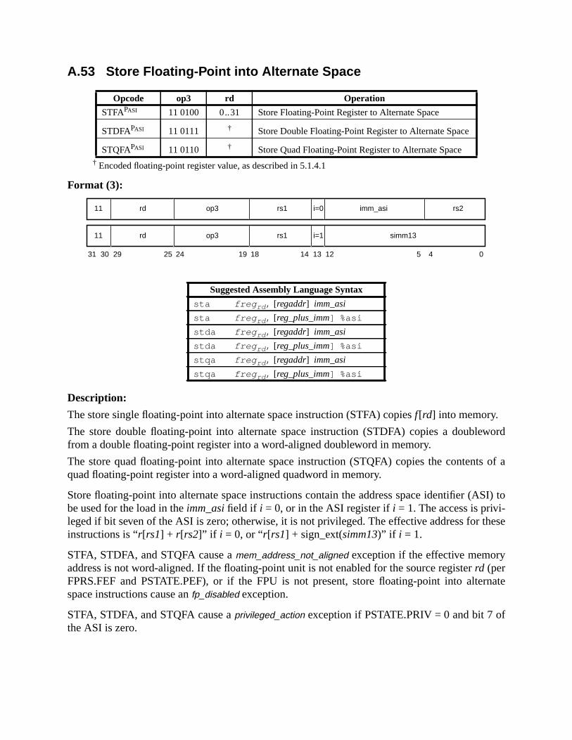
word
s of a
SI) to
hese
rnate
A.53 Store Floating-Point into Alternate Space
† Encoded floating-point register value, as described in 5.1.4.1
Format (3):
Description:
The store single floating-point into alternate space instruction (STFA) copiesf[rd] into memory.
The store double floating-point into alternate space instruction (STDFA) copies a doublefrom a double floating-point register into a word-aligned doubleword in memory.
The store quad floating-point into alternate space instruction (STQFA) copies the contentquad floating-point register into a word-aligned quadword in memory.
Store floating-point into alternate space instructions contain the address space identifier (Abe used for the load in theimm_asifield if i = 0, or in the ASI register ifi = 1. The access is privi-leged if bit seven of the ASI is zero; otherwise, it is not privileged. The effective address for tinstructions is “r[rs1] + r[rs2]” if i = 0, or “r[rs1] + sign_ext(simm13)” if i = 1.
STFA, STDFA, and STQFA cause amem_address_not_aligned exception if the effective memoryaddress is not word-aligned. If the floating-point unit is not enabled for the source registerrd (perFPRS.FEF and PSTATE.PEF), or if the FPU is not present, store floating-point into altespace instructions cause anfp_disabled exception.
STFA, STDFA, and STQFA cause aprivileged_action exception if PSTATE.PRIV = 0 and bit 7 ofthe ASI is zero.
Opcode op3 rd Operation
STFAPASI 11 0100 0..31 Store Floating-Point Register to Alternate Space
STDFAPASI 11 0111 † Store Double Floating-Point Register to Alternate Space
STQFAPASI 11 0110 † Store Quad Floating-Point Register to Alternate Space
Suggested Assembly Language Syntax
sta freg rd , [regaddr] imm_asi
sta freg rd , [reg_plus_imm] %asi
stda freg rd , [regaddr] imm_asi
stda freg rd , [reg_plus_imm] %asi
stqa freg rd , [regaddr] imm_asi
stqa freg rd , [reg_plus_imm] %asi
31 24 02530 29 19 18
rd11 op3 imm_asi
14 13 12 5 4
rs1 rs2i=0
rd11 op3 rs1 simm13i=1

e thatstoresen they
IMPL. DEP. #110(2): STDFA requires only word alignment in memory. If the effective address is word-aligned but not doubleword-aligned, it may cause an STDF_mem_address_not_aligned exception. In thiscase the trap handler software shall emulate the STDFA instruction and return.
IMPL. DEP. #112(2): STQFA requires only word alignment in memory. If the effective address is word-aligned but not quadword-aligned, it may cause an STQF_mem_address_not_aligned exception. In thiscase the trap handler software shall emulate the STQFA instruction and return.
Programming Note:In SPARC-V8, some compilers issued sets of single-precision stores when they could not determindouble- or quadword operands were properly aligned. For SPARC-V9, since emulation of misalignedis expected to be fast, it is recommended that compilers issue sets of single-precision stores only whcan determine that double- or quadword operands arenot properly aligned.
Exceptions:async_data_errorfp_disabledmem_address_not_alignedSTDF_mem_address_not_aligned (STDFA only) (impl. dep. #110)STQF_mem_address_not_aligned (STQFA only) (impl. dep. #112)privileged_actiondata_access_exceptiondata_access_protectiondata_access_MMU_missdata_access_errorfp_exception_other (invalid_fp_register (STQFA only))
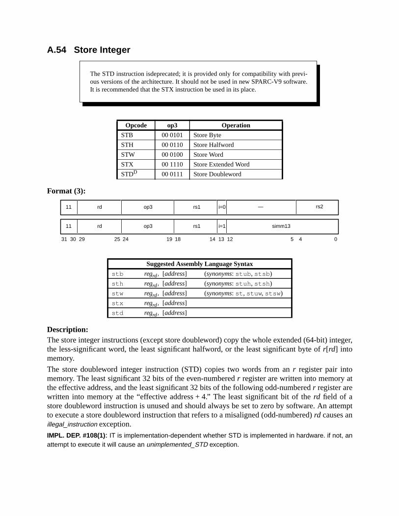
teger,
t
ttempt
A.54 Store Integer
Format (3):
Description:The store integer instructions (except store doubleword) copy the whole extended (64-bit) inthe less-significant word, the least significant halfword, or the least significant byte ofr[rd] intomemory.
The store doubleword integer instruction (STD) copies two words from anr register pair intomemory. The least significant 32 bits of the even-numberedr register are written into memory athe effective address, and the least significant 32 bits of the following odd-numberedr register arewritten into memory at the “effective address + 4.” The least significant bit of therd field of astore doubleword instruction is unused and should always be set to zero by software. An ato execute a store doubleword instruction that refers to a misaligned (odd-numbered)rd causes anillegal_instruction exception.
IMPL. DEP. #108(1): IT is implementation-dependent whether STD is implemented in hardware. if not, anattempt to execute it will cause an unimplemented_STD exception.
Opcode op3 Operation
STB 00 0101 Store Byte
STH 00 0110 Store Halfword
STW 00 0100 Store Word
STX 00 1110 Store Extended Word
STDD 00 0111 Store Doubleword
Suggested Assembly Language Syntax
stb regrd, [address] (synonyms: stub , stsb )
sth regrd, [address] (synonyms: stuh , stsh )
stw regrd, [address] (synonyms: st , stuw , stsw )
stx regrd, [address]
std regrd, [address]
The STD instruction isdeprecated; it is provided only for compatibility with previ-ous versions of the architecture. It should not be used in new SPARC-V9 software.It is recommended that the STX instruction be used in its place.
31 24 02530 29 19 18 14 13 12 5 4
rd11 op3 rs1 simm13i=1
rd11 op3 rs1 i=0 — rs2
ically.
d.d.e-
useulation
The effective address for these instructions is “r[rs1] + r[rs2]” if i = 0, or“ r[rs1] + sign_ext(simm13)” if i = 1.
A successful store (notably, store extended and store doubleword) instruction operates atom
STH causes amem_address_not_aligned exception if the effective address is not halfword-aligneSTW causes amem_address_not_aligned exception if the effective address is not word-aligneSTX and STD causes amem_address_not_aligned exception if the effective address is not doublword-aligned.
Programming Note:STD is provided for compatibility with SPARC-V8. It may execute slowly on SPARC-V9 machines becaof data path and register-access difficulties. In some SPARC-V9 systems it may cause a trap to emcode; therefore, STD should be avoided.
If STD is emulated in software, STX should be used in order to preserve atomicity.
Compatibility Note:The SPARC-V8 ST instruction has been renamed STW in SPARC-V9.
Exceptions:async_data_errorunimplemented_STD (STD only) (impl. dep. #108)illegal_instruction (STD with oddrd)mem_address_not_aligned (all except STB)data_access_exceptiondata_access_errordata_access_protectiondata_access_MMU_miss
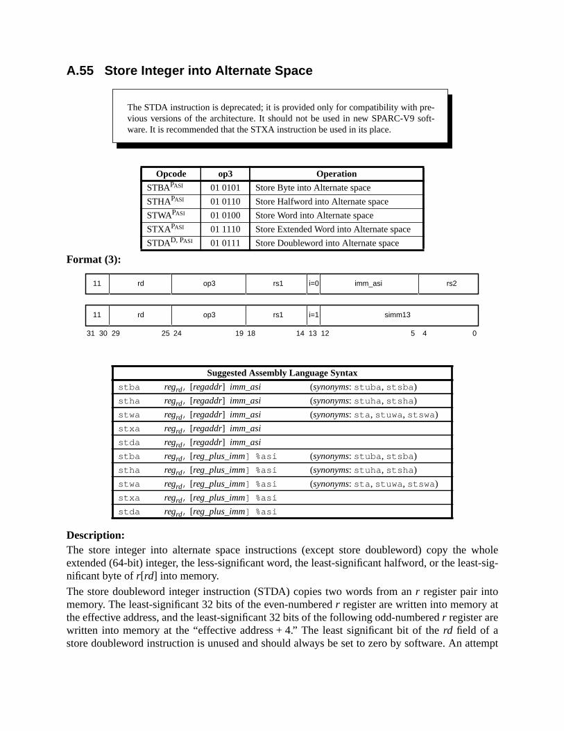
wholet-sig-
t
ttempt
A.55 Store Integer into Alternate Space
Format (3):
Description:The store integer into alternate space instructions (except store doubleword) copy theextended (64-bit) integer, the less-significant word, the least-significant halfword, or the leasnificant byte ofr[rd] into memory.
The store doubleword integer instruction (STDA) copies two words from anr register pair intomemory. The least-significant 32 bits of the even-numberedr register are written into memory athe effective address, and the least-significant 32 bits of the following odd-numberedr register arewritten into memory at the “effective address + 4.” The least significant bit of therd field of astore doubleword instruction is unused and should always be set to zero by software. An a
Opcode op3 Operation
STBAPASI 01 0101 Store Byte into Alternate space
STHAPASI 01 0110 Store Halfword into Alternate space
STWAPASI 01 0100 Store Word into Alternate space
STXAPASI 01 1110 Store Extended Word into Alternate space
STDAD, PASI 01 0111 Store Doubleword into Alternate space
Suggested Assembly Language Syntax
stba regrd, [regaddr] imm_asi (synonyms: stuba , stsba )
stha regrd, [regaddr] imm_asi (synonyms: stuha , stsha )
stwa regrd, [regaddr] imm_asi (synonyms: sta , stuwa , stswa )
stxa regrd, [regaddr] imm_asi
stda regrd, [regaddr] imm_asi
stba regrd, [reg_plus_imm] %asi (synonyms: stuba , stsba )
stha regrd, [reg_plus_imm] %asi (synonyms: stuha , stsha )
stwa regrd, [reg_plus_imm] %asi (synonyms: sta , stuwa , stswa )
stxa regrd, [reg_plus_imm] %asi
stda regrd, [reg_plus_imm] %asi
The STDA instruction is deprecated; it is provided only for compatibility with pre-vious versions of the architecture. It should not be used in new SPARC-V9 soft-ware. It is recommended that the STXA instruction be used in its place.
31 24 02530 29 19 18
rd11 op3 imm_asi
14 13 12 5 4
rs1 rs2i=0
rd11 op3 rs1 simm13i=1

e used
truc-
ically.
--
s
esto emu-
to execute a store doubleword instruction that refers to a misaligned (odd-numbered)rd causes anillegal_instruction exception.
IMPL. DEP. #108(2): It is implementation-dependent whether STDA is implemented in hardware. If not, anattempt to execute it will cause an unimplemented_STD exception.
Store integer to alternate space instructions contain the address space identifier (ASI) to bfor the store in theimm_asifield if i = 0, or in the ASI register ifi = 1. The access is privileged ifbit seven of the ASI is zero; otherwise, it is not privileged. The effective address for these instions is “r[rs1] + r[rs2]” if i = 0, or “r[rs1]+sign_ext(simm13)” if i = 1.
A successful store (notably, store extended and store doubleword) instruction operates atom
STHA causes amem_address_not_aligned exception if the effective address is not halfwordaligned. STWA causes amem_address_not_aligned exception if the effective address is not wordaligned. STXA and STDA cause amem_address_not_aligned exception if the effective address inot doubleword-aligned.
A store integer into alternate space instruction causes aprivileged_action exception ifPSTATE.PRIV = 0 and bit 7 of the ASI is zero.
Programming Note:STDA is provided for compatibility with SPARC-V8. It may execute slowly on SPARC-V9 machinbecause of data path and register-access difficulties. In some SPARC-V9 systems it may cause a traplation code; therefore, STDA should be avoided.
If STDA is emulated in software, STXA should be used in order to preserve atomicity.
Compatibility Note:The SPARC-V8 STA instruction is renamed STWA in SPARC-V9.
Exceptions:async_data_errorunimplemented_STD (STDA only) (impl. dep. #108)illegal_instruction (STDA with oddrd)privileged_actionmem_address_not_aligned (all except STBA)data_access_exceptiondata_access_errordata_access_protectiondata_access_MMU_miss

) of
thetic
A.56 Subtract
Format (3):
Description:
These instructions compute “r[rs1] – r[rs2]” if i = 0, or “r[rs1] – sign_ext(simm13)” if i = 1, andwrite the difference intor[rd].
SUBC and SUBCcc (“SUBtract with carry”) also subtract the CCR register’s 32-bit carry (icc.c)bit; that is, they compute “r[rs1] – r[rs2] – icc.c” or “ r[rs1] – sign_ext(simm13) –icc.c,” and writethe difference intor[rd].
SUBcc and SUBCcc modify the integer condition codes (CCR.icc and CCR.xcc). 32-bit overflow(CCR.icc.v) occurs on subtraction if bit 31 (the sign) of the operands differ and bit 31 (the signthe difference differs fromr[rs1]<31>. 64-bit overflow (CCR.xcc.v) occurs on subtraction if bit 63(the sign) of the operands differ and bit 63 (the sign) of the difference differs fromr[rs1]<63>.Programming Note:
A SUBcc withrd = 0 can be used to effect a signed or unsigned integer comparison. See the CMP syninstruction in Appendix G.
Programming Note:SUBC and SUBCcc read the 32-bit condition codes’ carry bit (CCR.icc.c), not the 64-bit condition codes’carry bit (CCR.xcc.c).
Compatibility Note:SUBC and SUBCcc were named SUBX and SUBXcc, respectively, in SPARC-V8.
Exceptions:(none)
Opcode op3 Operation
SUB 00 0100 Subtract
SUBcc 01 0100 Subtract and modify cc’s
SUBC 00 1100 Subtract with Carry
SUBCcc 01 1100 Subtract with Carry and modify cc’s
Suggested Assembly Language Syntax
sub regrs1, reg_or_imm, regrd
subcc regrs1, reg_or_imm, regrd
subc regrs1, reg_or_imm, regrd
subccc regrs1, reg_or_imm, regrd
31 24 02530 29 19 18
rd10 op3 —
14 13 12 5 4
rs1 rs2i=0
rd10 op3 rs1 simm13i=1
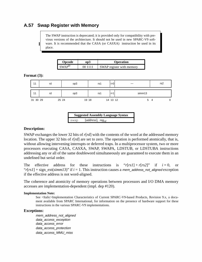
ryis,
morensm in an
mory
docu-these
A.57 Swap Register with Memory
Format (3):
Description:
SWAP exchanges the lower 32 bits ofr[rd] with the contents of the word at the addressed memolocation. The upper 32 bits ofr[rd] are set to zero. The operation is performed atomically, thatwithout allowing intervening interrupts or deferred traps. In a multiprocessor system, two orprocessors executing CASA, CASXA, SWAP, SWAPA, LDSTUB, or LDSTUBA instructioaddressing any or all of the same doubleword simultaneously are guaranteed to execute theundefined but serial order.
The effective address for these instructions is “r[rs1] + r[rs2]” if i = 0, or“ r[rs1] + sign_ext(simm13)” if i = 1. This instruction causes amem_address_not_aligned exceptionif the effective address is not word-aligned.
The coherence and atomicity of memory operations between processors and I/O DMA meaccesses are implementation-dependent (impl. dep #120).
Implementation Note:See <Italic>Implementation Characteristics of Current SPARC-V9-based Products, Revision 9.x, ament available from SPARC International, for information on the presence of hardware support forinstructions in the various SPARC-V9 implementations.
Exceptions:mem_address_not_aligneddata_access_exceptiondata_access_errordata_access_protectiondata_access_MMU_miss
Opcode op3 Operation
SWAPD 00 1111 SWAP register with memory
Suggested Assembly Language Syntax
swap [address], regrd
The SWAP instruction is deprecated; it is provided only for compatibility with pre-vious versions of the architecture. It should not be used in new SPARC-V9 soft-ware. It is recommended that the CASA (or CASXA) instruction be used in itsplace.
31 24 02530 29 19 18 14 13 12 5 4
rd11 op3 rs1 simm13i=1
rd11 op3 rs1 i=0 — rs2

async_data_error
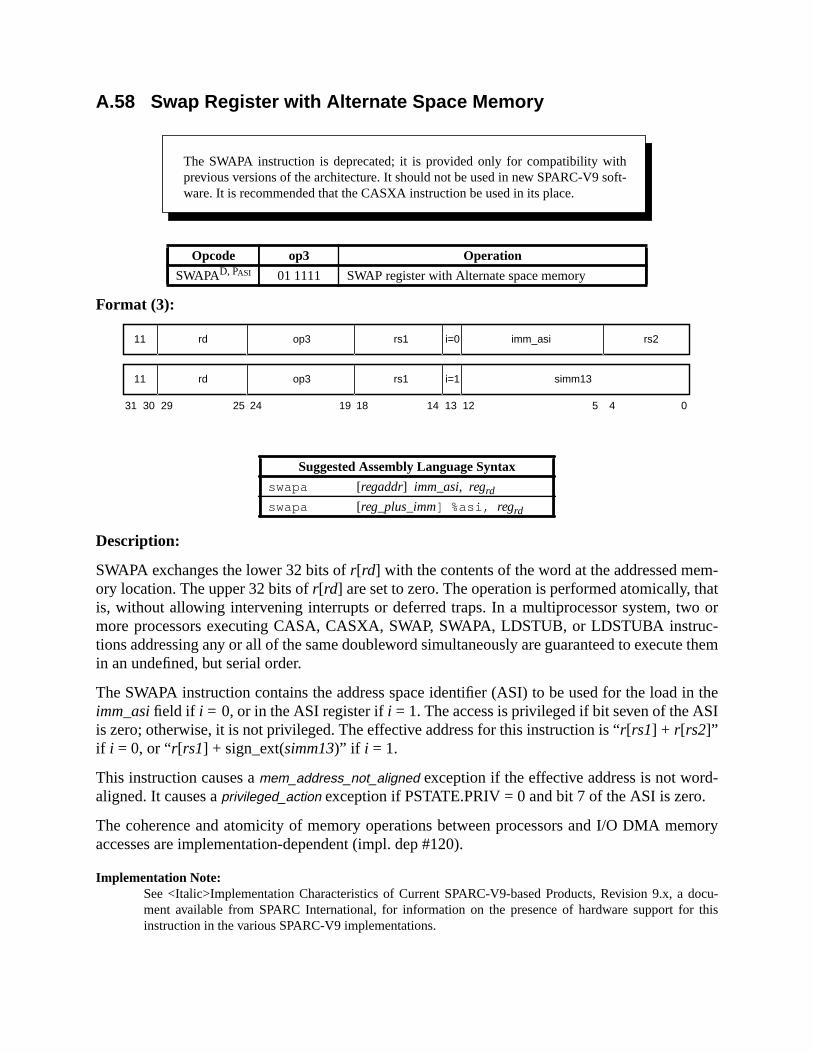
m-ato orc-
te them
in theI
-
mory
docu-r this
A.58 Swap Register with Alternate Space Memory
Format (3):
Description:
SWAPA exchanges the lower 32 bits ofr[rd] with the contents of the word at the addressed meory location. The upper 32 bits ofr[rd] are set to zero. The operation is performed atomically, this, without allowing intervening interrupts or deferred traps. In a multiprocessor system, twmore processors executing CASA, CASXA, SWAP, SWAPA, LDSTUB, or LDSTUBA instrutions addressing any or all of the same doubleword simultaneously are guaranteed to execuin an undefined, but serial order.
The SWAPA instruction contains the address space identifier (ASI) to be used for the loadimm_asifield if i = 0, or in the ASI register ifi = 1. The access is privileged if bit seven of the ASis zero; otherwise, it is not privileged. The effective address for this instruction is “r[rs1] + r[rs2]”if i = 0, or “r[rs1] + sign_ext(simm13)” if i = 1.
This instruction causes amem_address_not_aligned exception if the effective address is not wordaligned. It causes aprivileged_action exception if PSTATE.PRIV = 0 and bit 7 of the ASI is zero.
The coherence and atomicity of memory operations between processors and I/O DMA meaccesses are implementation-dependent (impl. dep #120).
Implementation Note:See <Italic>Implementation Characteristics of Current SPARC-V9-based Products, Revision 9.x, ament available from SPARC International, for information on the presence of hardware support foinstruction in the various SPARC-V9 implementations.
Opcode op3 Operation
SWAPAD, PASI 01 1111 SWAP register with Alternate space memory
Suggested Assembly Language Syntax
swapa [regaddr] imm_asi, regrd
swapa [reg_plus_imm] %asi, regrd
The SWAPA instruction is deprecated; it is provided only for compatibility withprevious versions of the architecture. It should not be used in new SPARC-V9 soft-ware. It is recommended that the CASXA instruction be used in its place.
31 24 02530 29 19 18
rd11 op3 imm_asi
14 13 12 5 4
rs1 rs2i=0
rd11 op3 rs1 simm13i=1

Exceptions:mem_address_not_alignedprivileged_actiondata_access_exceptiondata_access_errordata_access_protectiondata_access_MMU_missasync_data_error

en-31 of
um is
, theed
tic
-addit
A.59 Tagged Add
Format (3):
Description:
These instructions compute a sum that is “r[rs1] + r[rs2]” if i = 0, or “r[rs1] + sign_ext(simm13)”if i = 1.
TADDcc modifies the integer condition codes (icc andxcc), and TADDccTV does so also, if itdoes not trap.
A tag_overflow exception occurs if bit 1 or bit 0 of either operand is nonzero, or if the addition gerates 32-bit arithmetic overflow (i.e., both operands have the same value in bit 31, and bitthe sum is different).
If TADDccTV causes a tag overflow, atag_overflow exception is generated, andr[rd] and the inte-ger condition codes remain unchanged. If a TADDccTV does not cause a tag overflow, the swritten intor[rd], and the integer condition codes are updated. CCR.icc.v is set to 0 to indicate no32-bit overflow. If a TADDcc causes a tag overflow, the 32-bit overflow bit (CCR.icc.v) is set to 1;if it does not cause a tag overflow, CCR.icc.v is cleared.
In either case, the remaining integer condition codes (both the other CCR.icc bits and all theCCR.xccbits) are also updated as they would be for a normal ADD instruction. In particularsetting of the CCR.xcc.vbit is not determined by the tag overflow condition (tag overflow is usonly to set the 32-bit overflow bit). CCR.xcc.v is set only based on the normal 64-bit arithemeoverflow condition, like a normal 64-bit add.Compatibility Note:
TADDccTV traps based on the 32-bit overflow condition, just as in SPARC-V8. Although the taggedinstructions set the 64-bit condition codes CCR.xcc, there is no form of the instruction that traps the 64-boverflow condition.
Opcode op3 Operation
TADDcc 10 0000 Tagged Add and modify cc’s
TADDccTVD 10 0010 Tagged Add and modify cc’s, or Trap on Overflow
Suggested Assembly Language Syntax
taddcc regrs1, reg_or_imm, regrd
taddcctv regrs1, reg_or_imm, regrd
The TADDccTV instruction is deprecated; it is provided only for compatibilitywith previous versions of the architecture. It should not be used in new SPARC-V9software. It is recommended that TADDcc followed by BPVS be used in its place(with instructions to save the pre-TADDcc integer condition codes, if necessary).
31 24 02530 29 19 18
rd10 op3 —
14 13 12 5 4
rs1 rs2i=0
rd10 op3 rs1 simm13i=1

Exceptions:tag_overflow (TADDccTV only)

r
ratesbit)
dition,
bit
ular,isit
A.60 Tagged Subtract
Format (3):
Description:
These instructions compute “r[rs1] – r[rs2]” if i = 0, or “r[rs1] – sign_ext(simm13)” if i = 1.
TSUBcc modifies the integer condition codes (icc andxcc); TSUBccTV also modifies the integecondition codes, if it does not trap.
A tag overflow occurs if bit 1 or bit 0 of either operand is nonzero, or if the subtraction gene32-bit arithmetic overflow; that is, the operands have different values in bit 31 (the 32-bit signand the sign of the 32-bit difference in bit 31 differs from bit 31 ofr[rs1].
If TSUBccTV causes a tag overflow, atag_overflow exception is generated andr[rd] and the inte-ger condition codes remain unchanged. If a TSUBccTV does not cause a tag overflow conthe difference is written intor[rd], and the integer condition codes are updated. CCR.icc.v is set to0 to indicate no 32-bit overflow. If a TSUBcc causes a tag overflow, the 32-bit overflow(CCR.icc.v) is set to 1; if it does not cause a tag overflow, CCR.icc.v is cleared.
In either case, the remaining integer condition codes (both the other CCR.icc bits and all theCCR.xcc bits) are also updated as they would be for a normal subtract instruction. In particthe setting of the CCR.xcc.vbit is not determined by the tag overflow condition (tag overflowused only to set the 32-bit overflow bit). CCR.xcc.v is set only based on the normal 64-barithemetic overflow condition, like a normal 64-bit subtract.
Opcode op3 Operation
TSUBcc 10 0001 Tagged Subtract and modify cc’s
TSUBccTVD 10 0011 Tagged Subtract and modify cc’s, or Trap on Overflow
Suggested Assembly Language Syntax
tsubcc regrs1, reg_or_imm, regrd
tsubcctv regrs1, reg_or_imm, regrd
The TSUBccTV instruction is deprecated; it is provided only for compatibility withprevious versions of the architecture. It should not be used in new SPARC-V9 soft-ware. It is recommended that TSUBcc followed by BPVS be used in its place (withinstructions to save the pre-TSUBcc integer condition codes, if necessary).
31 24 02530 29 19 18
rd10 op3 —
14 13 12 5 4
rs1 rs2i=0
rd10 op3 rs1 simm13i=1

ged-n
Compatibility Note:TSUBccTV traps are based on the 32-bit overflow condition, just as in SPARC-V8. Although the tagsubtract instructions set the 64-bit condition codes CCR.xcc, there is no form of the instruction that traps o64-bit overflow.
Exceptions:tag_overflow (TSUBccTV only)

A.61 Trap on Integer Condition Codes (Tcc)
Format (4):
Opcode op3 cond Operation icc test
TA 11 1010 1000 Trap Always 1
TN 11 1010 0000 Trap Never 0
TNE 11 1010 1001 Trap on Not Equal not Z
TE 11 1010 0001 Trap on Equal Z
TG 11 1010 1010 Trap on Greater not (Z or (N xor V))
TLE 11 1010 0010 Trap on Less or Equal Z (N xor V)
TGE 11 1010 1011 Trap on Greater or Equal not (N xor V)
TL 11 1010 0011 Trap on Less N xor V
TGU 11 1010 1100 Trap on Greater Unsigned not (C or Z)
TLEU 11 1010 0100 Trap on Less or Equal Unsigned (C or Z)
TCC 11 1010 1101 Trap on Carry Clear(Greater than or Equal, Unsigned) not C
TCS 11 1010 0101 Trap on Carry Set (Less Than, Unsigned) C
TPOS 11 1010 1110 Trap on Positive or zero not N
TNEG 11 1010 0110 Trap on Negative N
TVC 11 1010 1111 Trap on Overflow Clear not V
TVS 11 1010 0111 Trap on Overflow Set V
cc1 cc0 Condition codes
00 icc
01 —
10 xcc
11 —
5 4
10 cond op3 rs1 i=0 — rs2
31 141924 18 13 12 02530 29
—
28 7 6
cc1cc0
11 10
10 cond op3 rs1 i=1 —— cc1cc0 sw_trap_#
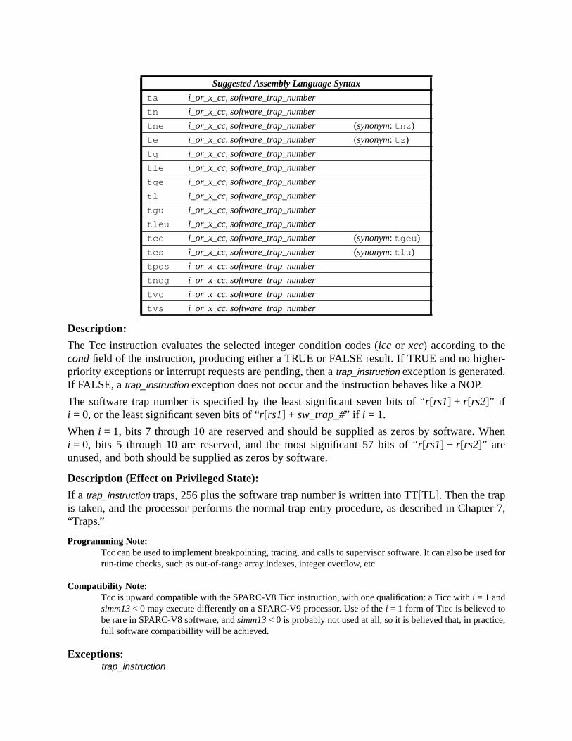
er-.
When
rappter 7,
sed for
e,
Description:
The Tcc instruction evaluates the selected integer condition codes (icc or xcc) according to thecondfield of the instruction, producing either a TRUE or FALSE result. If TRUE and no highpriority exceptions or interrupt requests are pending, then atrap_instruction exception is generatedIf FALSE, atrap_instruction exception does not occur and the instruction behaves like a NOP.
The software trap number is specified by the least significant seven bits of “r[rs1] + r[rs2]” ifi = 0, or the least significant seven bits of “r[rs1] + sw_trap_#” if i = 1.
When i = 1, bits 7 through 10 are reserved and should be supplied as zeros by software.i = 0, bits 5 through 10 are reserved, and the most significant 57 bits of “r[rs1] + r[rs2]” areunused, and both should be supplied as zeros by software.
Description (Effect on Privileged State):
If a trap_instruction traps, 256 plus the software trap number is written into TT[TL]. Then the tis taken, and the processor performs the normal trap entry procedure, as described in Cha“Traps.”
Programming Note:Tcc can be used to implement breakpointing, tracing, and calls to supervisor software. It can also be urun-time checks, such as out-of-range array indexes, integer overflow, etc.
Compatibility Note:Tcc is upward compatible with the SPARC-V8 Ticc instruction, with one qualification: a Ticc withi = 1 andsimm13< 0 may execute differently on a SPARC-V9 processor. Use of thei = 1 form of Ticc is believed tobe rare in SPARC-V8 software, andsimm13< 0 is probably not used at all, so it is believed that, in practicfull software compatibillity will be achieved.
Exceptions:trap_instruction
Suggested Assembly Language Syntax
ta i_or_x_cc, software_trap_number
tn i_or_x_cc, software_trap_number
tne i_or_x_cc, software_trap_number (synonym: tnz )
te i_or_x_cc, software_trap_number (synonym: tz )
tg i_or_x_cc, software_trap_number
tle i_or_x_cc, software_trap_number
tge i_or_x_cc, software_trap_number
tl i_or_x_cc, software_trap_number
tgu i_or_x_cc, software_trap_number
tleu i_or_x_cc, software_trap_number
tcc i_or_x_cc, software_trap_number (synonym: tgeu )
tcs i_or_x_cc, software_trap_number (synonym: tlu )
tpos i_or_x_cc, software_trap_number
tneg i_or_x_cc, software_trap_number
tvc i_or_x_cc, software_trap_number
tvs i_or_x_cc, software_trap_number

illegal_instruction (cc1 cc0= 012 or 112)

A.62 Write Privileged Register
Format (3):
Opcode op3 Operation
WRPRP 11 0010 Write Privileged Register
rd Privileged register
0 TPC
1 TNPC
2 TSTATE
3 TT
4 TICK
5 TBA
6 PSTATE
7 TL
8 PIL
9 CWP
10 CANSAVE
11 CANRESTORE
12 CLEANWIN
13 OTHERWIN
14 WSTATE
15..31 Reserved
31 24 02530 29 19 18
rd10 op3 —
14 13 12 5 4
rs1 rs2i=0
rd10 op3 rs1 simm13i=1

pera-
leastoneL). Aan
state.
care
g
ure;
e statetruc-
Description:
This instruction stores the value “r[rs1] xor r[rs2]” if i = 0, or “r[rs1] xor sign_ext(simm13)” ifi = 1 to the writable fields of the specified privileged state register. Note the exclusive-or otion.
The rd field in the instruction determines the privileged register that is written. There are atfour copies of the TPC, TNPC, TT, and TSTATE registers, one for each trap level. A write toof these registers sets the register indexed by the current value in the trap level register (Twrite to TPC, TNPC, TT, or TSTATE when the trap level is zero (TL = 0) causesillegal_instruction exception.
A WRPR of TL does not cause a trap or return from trap; it does not alter any other machineProgramming Note:
A WRPR of TL can be used to read the values of TPC, TNPC, and TSTATE for any trap level, however,must be taken that traps do not occur while the TL register is modified.
The WRPR instruction is anondelayed-write instruction. The instruction immediately followinthe WRPR observes any changes made to processor state made by the WRPR.
WRPR instructions withrd in the range 15..31 are reserved for future versions of the architectexecuting a WRPR instruction withrd in that range causes anillegal_instruction exception.Programming Note:
On an implementation that provides a floating-point queue, supervisor software should be aware of thof the FQ before disabling the floating-point unit (changing PSTATE.PEF from 1 to 0 with a WRPR instion) (impl. dep. #24). Typically, supervisor software ensures that the FQ is empty (FSR.qne= 0) before dis-abling the floating-point unit.
Exceptions:privileged_opcodeillegal_instruction ((rd = 15..31) or ((rd ≤ 3) and (TL = 0)))
Suggested Assembly Language Syntax
wrpr regrs1, reg_or_imm, %tpc
wrpr regrs1, reg_or_imm, %tnpc
wrpr regrs1, reg_or_imm, %tstate
wrpr regrs1, reg_or_imm, %tt
wrpr regrs1, reg_or_imm, %tick
wrpr regrs1, reg_or_imm, %tba
wrpr regrs1, reg_or_imm, %pstate
wrpr regrs1, reg_or_imm, %tl
wrpr regrs1, reg_or_imm, %pil
wrpr regrs1, reg_or_imm, %cwp
wrpr regrs1, reg_or_imm, %cansave
wrpr regrs1, reg_or_imm, %canrestore
wrpr regrs1, reg_or_imm, %cleanwin
wrpr regrs1, reg_or_imm, %otherwin
wrpr regrs1, reg_or_imm, %wstate
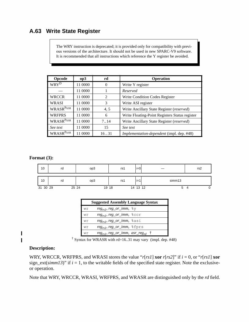
ive-
A.63 Write State Register
Format (3):
† Syntax for WRASR with rd=16..31 may vary (impl. dep. #48)
Description:
WRY, WRCCR, WRFPRS, and WRASI stores the value “r[rs1] xor r[rs2]” if i = 0, or “r[rs1] xorsign_ext(simm13)” if i = 1, to the writable fields of the specified state register. Note the exclusor operation.
Note that WRY, WRCCR, WRASI, WRFPRS, and WRASR are distinguished only by therd field.
Opcode op3 rd Operation
WRYD 11 0000 0 Write Y register
— 11 0000 1 Reserved
WRCCR 11 0000 2 Write Condition Codes Register
WRASI 11 0000 3 Write ASI register
WRASRPASR 11 0000 4, 5 Write Ancillary State Register (reserved)
WRFPRS 11 0000 6 Write Floating-Point Registers Status register
WRASRPASR 11 0000 7..14 Write Ancillary State Register (reserved)
See text 11 0000 15 See text
WRASRPASR 11 0000 16.. 31 Implementation-dependent (impl. dep. #48)
Suggested Assembly Language Syntax
wr regrs1, reg_or_imm, %y
wr regrs1, reg_or_imm, %ccr
wr regrs1, reg_or_imm, %asi
wr regrs1, reg_or_imm, %fprs
wr regrs1, reg_or_imm, asr_regrd †
The WRY instruction is deprecated; it is provided only for compatibility with previ-ous versions of the architecture. It should not be used in new SPARC-V9 software.It is recommended that all instructions which reference the Y register be avoided.
31 24 02530 29 19 18
rd10 op3 —
14 13 12 5 4
rs1 rs2i=0
rd10 op3 rs1 simm13i=1
ee
.
the
ew
PRS
l reg-9.x, aspe-
the
heASR
nden-re that
WRASR writes a value to the ancillary state register (ASR) indicated byrd. The operation per-formed to generate the value written may berd-dependent or implementation-dependent (sbelow). A WRASR instruction is indicated byop= 216, rd = 4, 5, or ≥ 7 andop3= 3016.
An instruction withop= 216, op3= 3016, rd = 15,rs1 = 0, andi = 1 is defined as a SIR instructionSee A.50, “Software-Initiated Reset.” Whenop= 216, op3= 3016, andrd = 15, if eitherrs1≠0 ori ≠1, then anillegal_instruction exception shall be generated.
IMPL. DEP. #48: WRASR instructions with rd in the range 16..31 are available for implementation-depen-dent uses (impl. dep. #8). For a WRASR instruction with rd in the range 16..31, the following are imple-mentation-dependent: the interpretation of bits 18:0 in the instruction, the operation(s) performed (forexample, XOR) to generate the value written to the ASR, whether the instruction is privileged (impl. dep.#9), and whether the instruction causes an illegal_instruction exception.
See I.1.1, “Read/Write Ancillary State Registers (ASRs),” for a discussion of extendingSPARC-V9 instruction set using read/write ASR instructions.
The WRY, WRCCR, WRFPRS, and WRASI instructions arenot delayed-write instructions. Theinstruction immediately following a WRY, WRCCR, WRFPRS, or WRASI observes the nvalue of the Y, CCR, FPRS, or ASI register.
WRFPRS waits for any pending floating-point operations to complete before writing the Fregister.
Implementation Note:Ancillary state registers may include (for example) timer, counter, diagnostic, self-test, and trap-controisters. See <Italic>Implementation Characteristics of Current SPARC-V9-based Products, Revisiondocument available from SPARC International, for information on ancillary state registers provided bycific implementations.
Compatibility Note:The SPARC-V8 WRIER, WRPSR, WRWIM, and WRTBR instructions do not exist in SPARC-V9, sinceIER, PSR, TBR, and WIM registers do not exist in SPARC-V9.
Exceptions:privileged_opcode (WRASR only; implementation-dependent (impl. dep. #48))illegal_instruction (WRASR with rd = 16..31 and the implementation does not define t
instruction as an extension; implementation-dependent (impl. dep. #48), or WRwith rd equal to 1, 4, 5, or in the range 7..14), WRASR withrd equal to 15 andrs1≠0or i ≠1
B IEEE Std 754-1985 Requirements for SPARC-V9The IEEE Std 754-1985 floating-point standard contains a number of implementation-depecies. This appendix specifies choices for these implementation-dependencies, to ensuSPARC-V9 implementations are as consistent as possible.
ating-
trap.
uteay betan
that
that
echa-
from,
thecessmat,cant
B.1 Traps Inhibit ResultsAs described in 5.1.7, “Floating-Point State Register (FSR),” and elsewhere, when a flopoint trap occurs:
— The destination floating-point register(s) (thef registers) are unchanged.
— The floating-point condition codes (fcc0, fcc1, fcc2, andfcc3) are unchanged.
— The FSR.aexc (accrued exceptions) field is unchanged.
— The FSR.cexc(current exceptions) field is unchanged except forIEEE_754_exceptions; inthat case,cexccontains a bit set to “1” corresponding to the exception that caused theOnly one bit shall be set incexc.
Instructions causing anfp_exception_other trap due to unfinished or unimplemented FPops execas if by hardware; that is, a trap is undetectable by user software, except that timing maffected. A user-mode trap handler invoked for anIEEE_754_exception, whether as a direct resulof a hardwarefp_exception_ieee_754 trap or as an indirect result of supervisor handling ofunfinished_FPop or unimplemented_FPop, can rely on the following:
— The address of the instruction that caused the exception will be available to it.
— The destination floating-point register(s) are unchanged from their state prior toinstruction’s execution.
— The floating-point condition codes (fcc0, fcc1, fcc2, andfcc3) are unchanged.
— The FSRaexc field is unchanged.
— The FSRcexcfield contains exactly one bit set to 1, corresponding to the exceptioncaused the trap.
— The FSRftt, qne, andreserved fields are zero.
Supervisor software is responsible for enforcing these requirements if the hardware trap mnism does not.
B.2 NaN Operand and Result Definitions
An untrapped floating-point result can be in a format that is either the same as, or differentthe format of the source operands. These two cases are described separately below.
B.2.1 Untrapped Result in Different Format from Operands
F[sdq]TO[sdq] with a quiet NaN operand:No exception caused; result is a quiet NaN. The operand is transformed as follows:
NaN transformation: The most significant bits of the operand fraction are copied tomost significant bits of the result fraction. When converting to a narrower format, exlow-order bits of the operand fraction are discarded. When converting to a wider forexcess low-order bits of the result fraction are set to 0. The quiet bit (the most signifi

es a.
uish
c-
bit of the result fraction) is always set to 1, so the NaN transformation always producquiet NaN. The sign bit is copied from the operand to the result without modification
F[sdq]TO[sdq] with a signaling NaN operand:Invalid exception; result is the signaling NaN operand processed by theNaN transforma-tion above to produce a quiet NaN.
FCMPE[sdq] with any NaN operand:Invalid exception; the selected floating-point condition code is set to unordered.
FCMP[sdq] with any signaling NaN operand:Invalid exception; the selected floating-point condition code is set to unordered.
FCMP[sdq] with any quiet NaN operand but no signaling NaN operand:No exception; the selected floating-point condition code is set to unordered.
B.2.2 Untrapped Result in Same Format as Operands
No NaN operand:For an invalid operation such assqrt(–1.0) or 0.0÷ 0.0, the result is the quiet NaN withsign = zero, exponent = all ones, and fraction = all ones. The sign is zero to distingsuch results from storage initialized to all ones.
One operand, a quiet NaN:No exception; result is the quiet NaN operand.
One operand, a signaling NaN:Invalid exception; result is the signaling NaN with its quiet bit (most significant bit of fration field) set to 1.
Two operands, both quiet NaNs:No exception; result is thers2 (second source) operand.
Two operands, both signaling NaNs:Invalid exception; result is thers2 operand with the quiet bit set to 1.
Two operands, only one a signaling NaN:Invalid exception; result is the signaling NaN operand with the quiet bit set to 1.
Two operands, neither a signaling NaN, only one a quiet NaN:No exception; result is the quiet NaN operand.

p-rands
st nor-
d over-els; if
st nor-r-
e
In table 27 NaNn means that the NaN is in rsn, Q means quiet, S signaling.
QSNaNn means a quiet NaN produced by theNaN transformation on a signaling NaN from rsn;the invalid exception is always indicated. The QNaNn results in the table never generate an excetion, but IEEE 754 specifies several cases of invalid exceptions, and QNaN results from opethat are both numbers.
B.3 Trapped Underflow Definition (UFM = 1)Underflow occurs if the exact unrounded result has magnitude between zero and the smallemalized number in the destination format.
IMPL. DEP. #55: Whether tininess (in IEEE 754 terms) is detected before or after rounding is implementa-tion-dependent. It is recommended that tininess be detected before rounding.
Note that the wrapped exponent results intended to be delivered on trapped underflows anflows in IEEE 754 are irrelevant to SPARC-V9 at the hardware and supervisor software levthey are created at all, it would be by user software in a user-mode trap handler.
B.4 Untrapped Underflow Definition (UFM = 0)
Underflow occurs if the exact unrounded result has magnitude between zero and the smallemalized number in the destination format,and the correctly rounded result in the destination fomat is inexact.
Table 28 summarizes what happens when an exactunrounded valueu satisfying
0 ≤ |u| ≤ smallest normalized number
would round, if no trap intervened, to arounded valuer which might be zero, subnormal, or thsmallest normalized value. “UF” means underflow trap (with ufc set incexc), “NX” means inexacttrap (with nxc set incexc), “uf” means untrapped underflow exception (with ufc set incexcandufa inaexc), and “nx” means untrapped inexact exception (with nxc set incexc and nxa inaexc).
Table 27—Untrapped Floating-Point Results
rs2 operand
Number QNaN2 SNaN2
rs1operand
None IEEE 754 QNaN2 QSNaN2
Number IEEE 754 QNaN2 QSNaN2
QNaN1 QNaN1 QNaN2 QSNaN2
SNaN1 QSNaN1 QSNaN1 QSNaN2

-
pd: ifis 1,
pd: if
754-.
-V9nn
† If tininess is detected after rounding and NXM = 1, then NX, otherwise “None” (impl. dep.#55).
B.5 Integer Overflow Definition
F[sdq]TOi :When a NaN, infinity, large positive argument≥ 2147483648.0, or large negative argument≤ –2147483649.0 is converted to an integer, the invalid_current (nvc) bit of FSR.cexcshould be set andfp_exception_IEEE_754 should be raised. If the floating-point invalid trais disabled (FSR.TEM.NVM = 0), no trap occurs and a numerical result is generatethe sign bit of the operand is 0, the result is 2147483647; if the sign bit of the operandthe result is –2147483648.
F[sdq]TOx:When a NaN, infinity, large positive argument≥ 263, or large negative argument≤ –(263 + 1), is converted to an extended integer, the invalid_current (nvc) bit of FSR.cexcshould be set andfp_exception_IEEE_754 should be raised. If the floating-point invalid trais disabled (FSR.TEM.NVM = 0), no trap occurs and a numerical result is generatethe sign bit of the operand is 0, the result is 263 – 1; if the sign bit of the operand is 1, theresult is –263.
B.6 Floating-Point Nonstandard Mode
SPARC-V9 implementations are permitted but not encouraged to deviate from IEEE Std1985 requirements when the nonstandard mode (NS) bit of the FSR is set (impl. dep. #18)
C SPARC-V9 Implementation DependenciesThis appendixchapterprovides a summary of all implementation dependencies in the SPARCstandard. The notation “IMPL. DEP. #nn:” is used to identify the definition of an implementatiodependency; the notation “(impl. dep. #nn)” is used to identify a reference to an implementatiodependency. The numbernn provides an index into table 29 on page 282.
Table 28—Untrapped Floating-Point Underflow
Underflow trap:Inexact trap:
UFM = 1NXM = ?
UFM = 0NXM = 1
UFM = 0NXM = 0
u = r
r is minimum normal None None None
r is subnormal UF None None
r is zero None None None
u ≠ r
r is minimum normal UF† NX uf nx
r is subnormal UF NX uf nx
r is zero UF NX uf nx
rrentdesignocu-
byof the
xe-her anware
lementsation,
ion butents of
9 sys-teristic
uction)tency).RC-along
enta-
SPARC International maintains a document, <Italic>Implementation Characteristics of CuSPARC-V9-based Products, Revision 9.x, which describes the implementation-dependentfeatures of SPARC-V9-compliant implementations. Contact SPARC International for this dment at
SPARC International535 Middlefield Rd, Suite 210
Menlo Park, CA 94025(415) 321-8692
C.1 Definition of an Implementation Dependency
The SPARC-V9 architecture is amodel that specifies unambiguously the behavior observedsoftware on SPARC-V9 systems. Therefore, it does not necessarily describe the operationhardware of any actual implementation.
An implementation isnot required to execute every instruction in hardware. An attempt to ecute a SPARC-V9 instruction that is not implemented in hardware generates a trap. Whetinstruction is implemented directly by hardware, simulated by software, or emulated by firmis implementation-dependent (impl. dep. #1).
The two levels of SPARC-V9 compliance are described in 1.2.6, “SPARC-V9 Compliance.”
Some elements of the architecture are defined to be implementation-dependent. These einclude certain registers and operations that may vary from implementation to implementand are explicitly identified as such in thisappendixchapter.
Implementation elements (such as instructions or registers) that appear in an implementatare not defined in this document (or its updates) are not considered to be SPARC-V9 elemthat implementation.
C.2 Hardware Characteristics
Hardware characteristics that do not affect the behavior observed by software on SPARC-Vtems are not considered architectural implementation dependencies. A hardware characmay be relevant to the user system design (for example, the speed of execution of an instror may be transparent to the user (for example, the method used for achieving cache consisThe SPARC International document, <Italic>Implementation Characteristics of Current SPAV9-based Products, Revision 9.x, provides a useful list of these hardware characteristics,with the list of implementation-dependent design features of SPARC-V9-compliant implemtions.
In general, hardware characteristics deal with
— Instruction execution speed
— Whether instructions are implemented in hardware
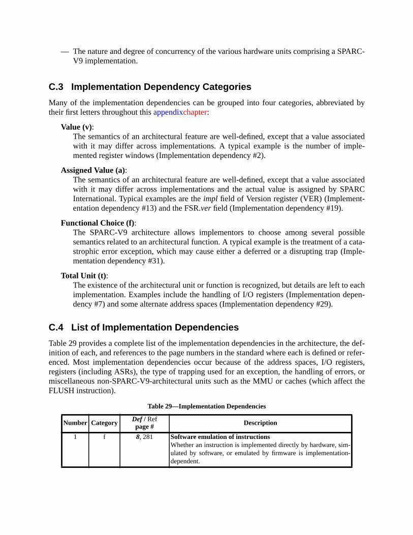
ARC-
ted by
ciatedle-
ciatedARC
siblecata-ple-
eachpen-
e def-r refer-gisters,
rs, orct the
— The nature and degree of concurrency of the various hardware units comprising a SPV9 implementation.
C.3 Implementation Dependency Categories
Many of the implementation dependencies can be grouped into four categories, abbreviatheir first letters throughout thisappendixchapter:
Value (v):The semantics of an architectural feature are well-defined, except that a value assowith it may differ across implementations. A typical example is the number of impmented register windows (Implementation dependency #2).
Assigned Value (a):The semantics of an architectural feature are well-defined, except that a value assowith it may differ across implementations and the actual value is assigned by SPInternational. Typical examples are theimpl field of Version register (VER) (Implement-entation dependency #13) and the FSR.ver field (Implementation dependency #19).
Functional Choice (f):The SPARC-V9 architecture allows implementors to choose among several possemantics related to an architectural function. A typical example is the treatment of astrophic error exception, which may cause either a deferred or a disrupting trap (Immentation dependency #31).
Total Unit (t) :The existence of the architectural unit or function is recognized, but details are left toimplementation. Examples include the handling of I/O registers (Implementation dedency #7) and some alternate address spaces (Implementation dependency #29).
C.4 List of Implementation Dependencies
Table 29 provides a complete list of the implementation dependencies in the architecture, thinition of each, and references to the page numbers in the standard where each is defined oenced. Most implementation dependencies occur because of the address spaces, I/O reregisters (including ASRs), the type of trapping used for an exception, the handling of erromiscellaneous non-SPARC-V9-architectural units such as the MMU or caches (which affeFLUSH instruction).
Table 29—Implementation Dependencies
Number Category Def / Refpage # Description
1 f 8, 281 Software emulation of instructionsWhether an instruction is implemented directly by hardware, sim-ulated by software, or emulated by firmware is implementation-dependent.
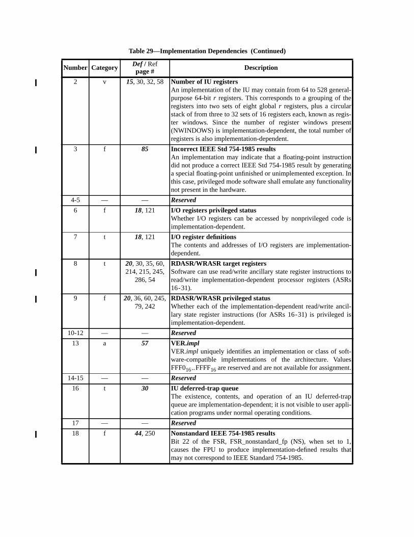
2 v 15, 30, 32, 58 Number of IU registersAn implementation of the IU may contain from 64 to 528 general-purpose 64-bitr registers. This corresponds to a grouping of theregisters into two sets of eight globalr registers, plus a circularstack of from three to 32 sets of 16 registers each, known as regis-ter windows. Since the number of register windows present(NWINDOWS) is implementation-dependent, the total number ofregisters is also implementation-dependent.
3 f 85 Incorrect IEEE Std 754-1985 resultsAn implementation may indicate that a floating-point instructiondid not produce a correct IEEE Std 754-1985 result by generatinga special floating-point unfinished or unimplemented exception. Inthis case, privileged mode software shall emulate any functionalitynot present in the hardware.
4-5 — — Reserved
6 f 18, 121 I/O registers privileged statusWhether I/O registers can be accessed by nonprivileged code isimplementation-dependent.
7 t 18, 121 I/O register definitionsThe contents and addresses of I/O registers are implementation-dependent.
8 t 20, 30, 35, 60,214, 215, 245,
286, 54
RDASR/WRASR target registersSoftware can use read/write ancillary state register instructions toread/write implementation-dependent processor registers (ASRs16-31).
9 f 20, 36, 60, 245,79, 242
RDASR/WRASR privileged statusWhether each of the implementation-dependent read/write ancil-lary state register instructions (for ASRs 16-31) is privileged isimplementation-dependent.
10-12 — — Reserved
13 a 57 VER.implVER.impl uniquely identifies an implementation or class of soft-ware-compatible implementations of the architecture. ValuesFFF016..FFFF16 are reserved and are not available for assignment.
14-15 — — Reserved
16 t 30 IU deferred-trap queueThe existence, contents, and operation of an IU deferred-trapqueue are implementation-dependent; it is not visible to user appli-cation programs under normal operating conditions.
17 — — Reserved
18 f 44, 250 Nonstandard IEEE 754-1985 resultsBit 22 of the FSR, FSR_nonstandard_fp (NS), when set to 1,causes the FPU to produce implementation-defined results thatmay not correspond to IEEE Standard 754-1985.
Table 29—Implementation Dependencies (Continued)
Number Category Def / Refpage # Description
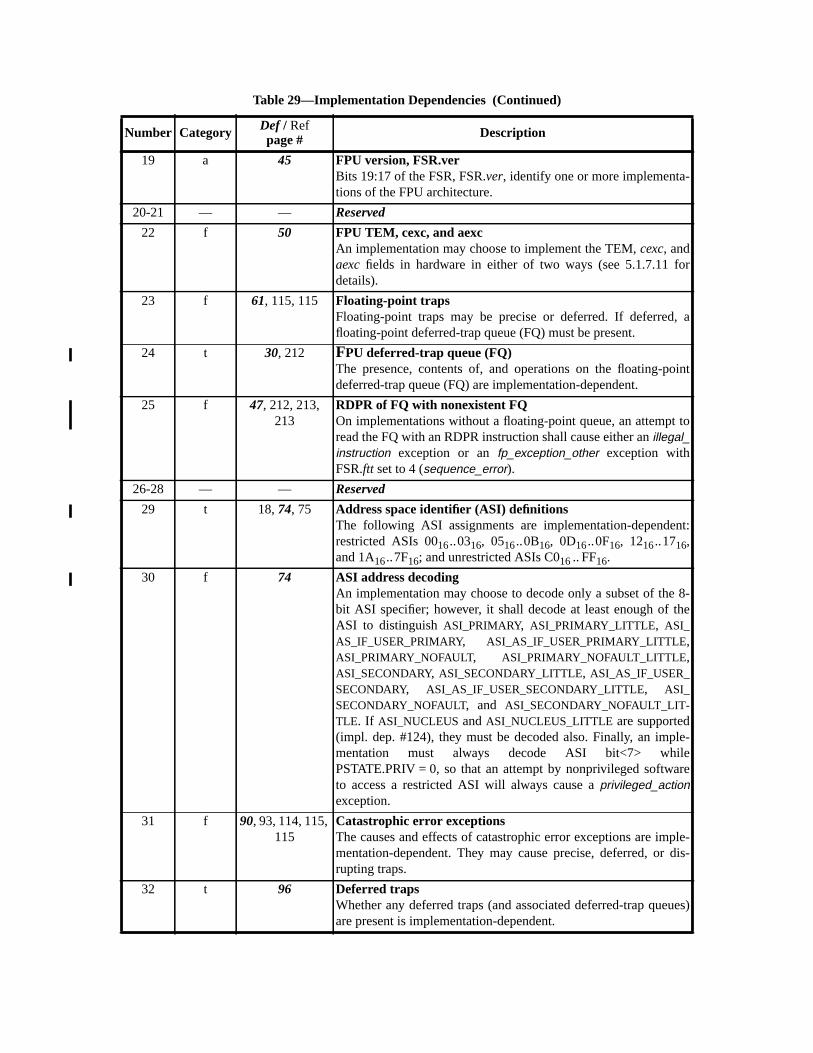
19 a 45 FPU version, FSR.verBits 19:17 of the FSR, FSR.ver, identify one or more implementa-tions of the FPU architecture.
20-21 — — Reserved
22 f 50 FPU TEM, cexc, and aexcAn implementation may choose to implement the TEM,cexc, andaexc fields in hardware in either of two ways (see 5.1.7.11 fordetails).
23 f 61, 115, 115 Floating-point trapsFloating-point traps may be precise or deferred. If deferred, afloating-point deferred-trap queue (FQ) must be present.
24 t 30, 212 FPU deferred-trap queue (FQ)The presence, contents of, and operations on the floating-pointdeferred-trap queue (FQ) are implementation-dependent.
25 f 47, 212, 213,213
RDPR of FQ with nonexistent FQOn implementations without a floating-point queue, an attempt toread the FQ with an RDPR instruction shall cause either anillegal_instruction exception or anfp_exception_other exception withFSR.ftt set to 4 (sequence_error).
26-28 — — Reserved
29 t 18,74, 75 Address space identifier (ASI) definitionsThe following ASI assignments are implementation-dependent:restricted ASIs 0016..0316, 0516..0B16, 0D16..0F16, 1216..1716,and 1A16..7F16; and unrestricted ASIs C016.. FF16.
30 f 74 ASI address decodingAn implementation may choose to decode only a subset of the 8-bit ASI specifier; however, it shall decode at least enough of theASI to distinguishASI_PRIMARY, ASI_PRIMARY_LITTLE, ASI_AS_IF_USER_PRIMARY, ASI_AS_IF_USER_PRIMARY_LITTLE,ASI_PRIMARY_NOFAULT, ASI_PRIMARY_NOFAULT_LITTLE,ASI_SECONDARY, ASI_SECONDARY_LITTLE, ASI_AS_IF_USER_SECONDARY, ASI_AS_IF_USER_SECONDARY_LITTLE, ASI_SECONDARY_NOFAULT, and ASI_SECONDARY_NOFAULT_LIT-TLE. If ASI_NUCLEUSandASI_NUCLEUS_LITTLE are supported(impl. dep. #124), they must be decoded also. Finally, an imple-mentation must always decode ASI bit<7> whilePSTATE.PRIV = 0, so that an attempt by nonprivileged softwareto access a restricted ASI will always cause aprivileged_actionexception.
31 f 90, 93, 114, 115,115
Catastrophic error exceptionsThe causes and effects of catastrophic error exceptions are imple-mentation-dependent. They may cause precise, deferred, or dis-rupting traps.
32 t 96 Deferred trapsWhether any deferred traps (and associated deferred-trap queues)are present is implementation-dependent.
Table 29—Implementation Dependencies (Continued)
Number Category Def / Refpage # Description
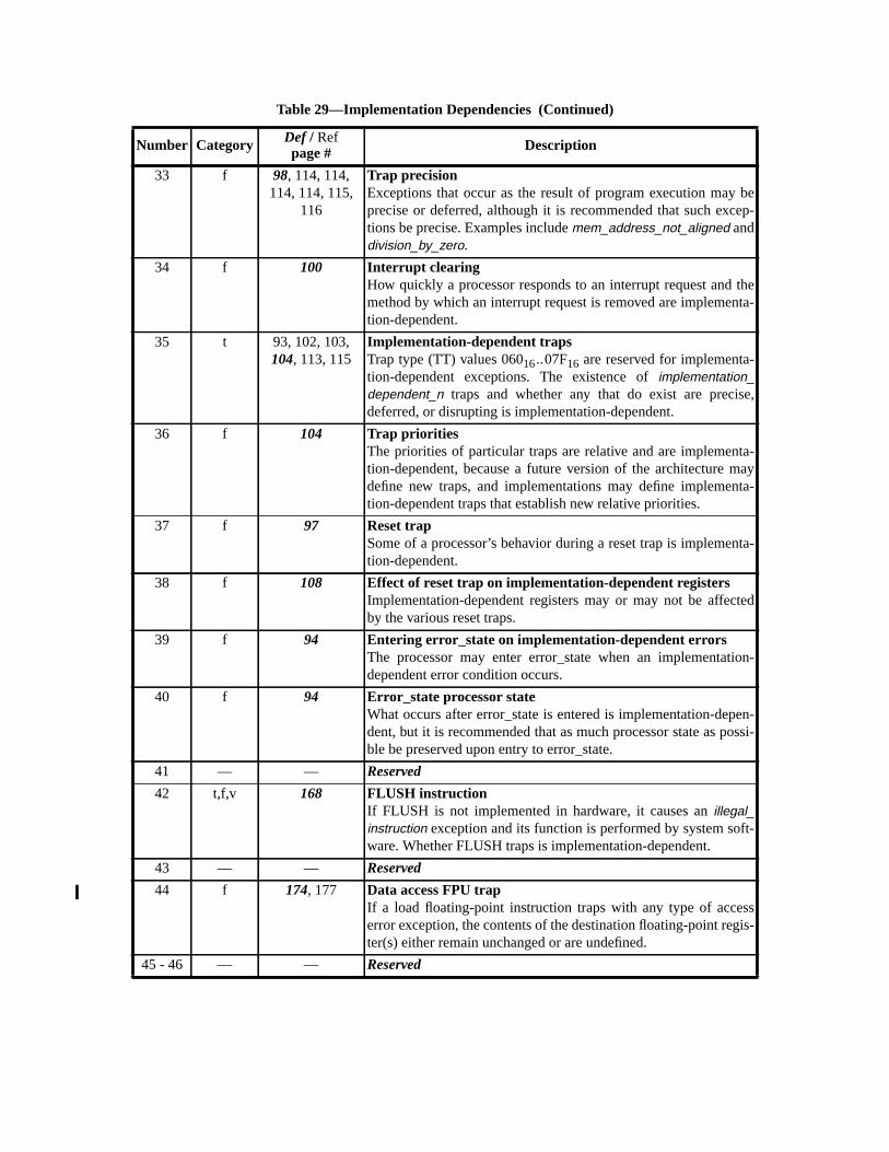
33 f 98, 114, 114,114, 114, 115,
116
Trap precisionExceptions that occur as the result of program execution may beprecise or deferred, although it is recommended that such excep-tions be precise. Examples includemem_address_not_aligned anddivision_by_zero.
34 f 100 Interrupt clearingHow quickly a processor responds to an interrupt request and themethod by which an interrupt request is removed are implementa-tion-dependent.
35 t 93, 102, 103,104, 113, 115
Implementation-dependent trapsTrap type (TT) values 06016..07F16 are reserved for implementa-tion-dependent exceptions. The existence ofimplementation_dependent_n traps and whether any that do exist are precise,deferred, or disrupting is implementation-dependent.
36 f 104 Trap prioritiesThe priorities of particular traps are relative and are implementa-tion-dependent, because a future version of the architecture maydefine new traps, and implementations may define implementa-tion-dependent traps that establish new relative priorities.
37 f 97 Reset trapSome of a processor’s behavior during a reset trap is implementa-tion-dependent.
38 f 108 Effect of reset trap on implementation-dependent registersImplementation-dependent registers may or may not be affectedby the various reset traps.
39 f 94 Entering error_state on implementation-dependent errorsThe processor may enter error_state when an implementation-dependent error condition occurs.
40 f 94 Error_state processor stateWhat occurs after error_state is entered is implementation-depen-dent, but it is recommended that as much processor state as possi-ble be preserved upon entry to error_state.
41 — — Reserved
42 t,f,v 168 FLUSH instructionIf FLUSH is not implemented in hardware, it causes anillegal_instruction exception and its function is performed by system soft-ware. Whether FLUSH traps is implementation-dependent.
43 — — Reserved
44 f 174, 177 Data access FPU trapIf a load floating-point instruction traps with any type of accesserror exception, the contents of the destination floating-point regis-ter(s) either remain unchanged or are undefined.
45 - 46 — — Reserved
Table 29—Implementation Dependencies (Continued)
Number Category Def / Refpage # Description
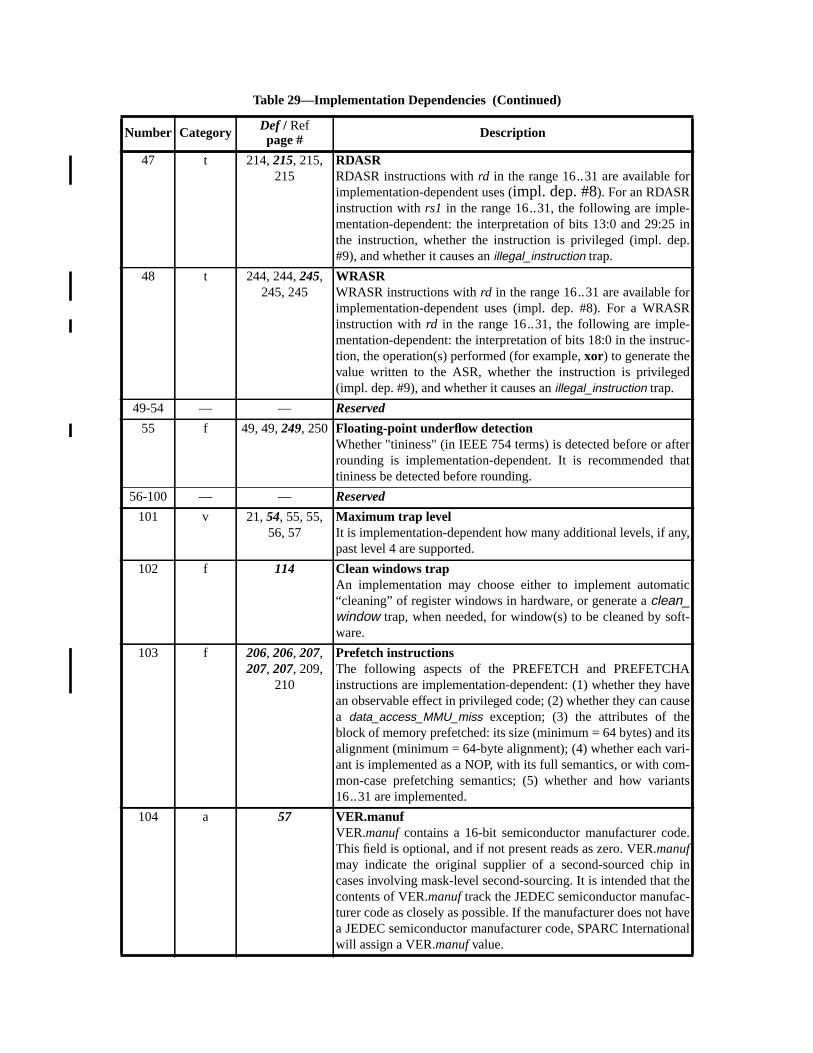
47 t 214,215, 215,215
RDASRRDASR instructions withrd in the range 16..31 are available forimplementation-dependent uses (impl. dep. #8). For an RDASRinstruction withrs1 in the range 16..31, the following are imple-mentation-dependent: the interpretation of bits 13:0 and 29:25 inthe instruction, whether the instruction is privileged (impl. dep.#9), and whether it causes anillegal_instruction trap.
48 t 244, 244,245,245, 245
WRASRWRASR instructions withrd in the range 16..31 are available forimplementation-dependent uses (impl. dep. #8). For a WRASRinstruction withrd in the range 16..31, the following are imple-mentation-dependent: the interpretation of bits 18:0 in the instruc-tion, the operation(s) performed (for example,xor) to generate thevalue written to the ASR, whether the instruction is privileged(impl. dep. #9), and whether it causes anillegal_instruction trap.
49-54 — — Reserved
55 f 49, 49,249, 250 Floating-point underflow detectionWhether "tininess" (in IEEE 754 terms) is detected before or afterrounding is implementation-dependent. It is recommended thattininess be detected before rounding.
56-100 — — Reserved
101 v 21,54, 55, 55,56, 57
Maximum trap levelIt is implementation-dependent how many additional levels, if any,past level 4 are supported.
102 f 114 Clean windows trapAn implementation may choose either to implement automatic“cleaning” of register windows in hardware, or generate aclean_window trap, when needed, for window(s) to be cleaned by soft-ware.
103 f 206, 206, 207,207, 207, 209,
210
Prefetch instructionsThe following aspects of the PREFETCH and PREFETCHAinstructions are implementation-dependent: (1) whether they havean observable effect in privileged code; (2) whether they can causea data_access_MMU_miss exception; (3) the attributes of theblock of memory prefetched: its size (minimum = 64 bytes) and itsalignment (minimum = 64-byte alignment); (4) whether each vari-ant is implemented as a NOP, with its full semantics, or with com-mon-case prefetching semantics; (5) whether and how variants16..31 are implemented.
104 a 57 VER.manufVER.manufcontains a 16-bit semiconductor manufacturer code.This field is optional, and if not present reads as zero. VER.manufmay indicate the original supplier of a second-sourced chip incases involving mask-level second-sourcing. It is intended that thecontents of VER.manuftrack the JEDEC semiconductor manufac-turer code as closely as possible. If the manufacturer does not havea JEDEC semiconductor manufacturer code, SPARC Internationalwill assign a VER.manuf value.
Table 29—Implementation Dependencies (Continued)
Number Category Def / Refpage # Description

105 f 51 TICK registerThe difference between the values read from the TICK register ontwo reads should reflect the number of processor cycles executedbetween the reads. If an accurate count cannot always be returned,any inaccuracy should be small, bounded, and documented. Animplementation may implement fewer than 63 bits inTICK.counter; however, the counter as implemented must be ableto count for at least 10 years without overflowing. Any upper bitsnot implemented must read as zero.
106 f 85,171 IMPDEPn instructionsThe IMPDEP1 and IMPDEP2 instructions are completely imple-mentation-dependent. Implementation-dependent aspects includetheir operation, the interpretation of bits 29:25 and 18:0 in theirencodings, and which (if any) exceptions they may cause.
107 f 179, 179,181,181
Unimplemented LDD trapIt is implementation-dependent whether LDD and LDDA areimplemented in hardware. If not, an attempt to execute either willcause anunimplemented_LDD trap.
108 f 117,229, 230,232, 232
Unimplemented STD trapIt is implementation-dependent whether STD and STDA areimplemented in hardware. If not, an attempt to execute either willcause anunimplemented_STD trap.
109 f 115,174, 174,177
LDDF_mem_address_not_alignedLDDF and LDDFA require only word alignment. However, if theeffective address is word-aligned but not doubleword-aligned,either may cause anLDDF_mem_address_not_aligned trap, inwhich case the trap handler software shall emulate the LDDF (orLDDFA) instruction and return.
110 f 116,226, 226,228, 228
STDF_mem_address_not_alignedSTDF and STDFA require only word alignment in memory. How-ever, if the effective address is word-aligned but not doubleword-aligned, either may cause anSTDF_mem_address_not_alignedtrap, in which case the trap handler software shall emulate theSTDF or STDFA instruction and return.
111 f 116,174, 174,177
LDQF_mem_address_not_alignedLDQF and LDQFA require only word alignment. However, if theeffective address is word-aligned but not quadword-aligned, eithermay cause anLDQF_mem_address_not_aligned trap, in whichcase the trap handler software shall emulate the LDQF (orLDQFA) instruction and return.
112 f 117,226, 226,228, 228
STQF_mem_address_not_alignedSTQF and STQFA require only word alignment in memory. How-ever, if the effective address is word-aligned but not quadword-aligned, either may cause anSTQF_mem_address_not_alignedtrap, in which case the trap handler software shall emulate theSTQF or STQFA instruction and return.
Table 29—Implementation Dependencies (Continued)
Number Category Def / Refpage # Description
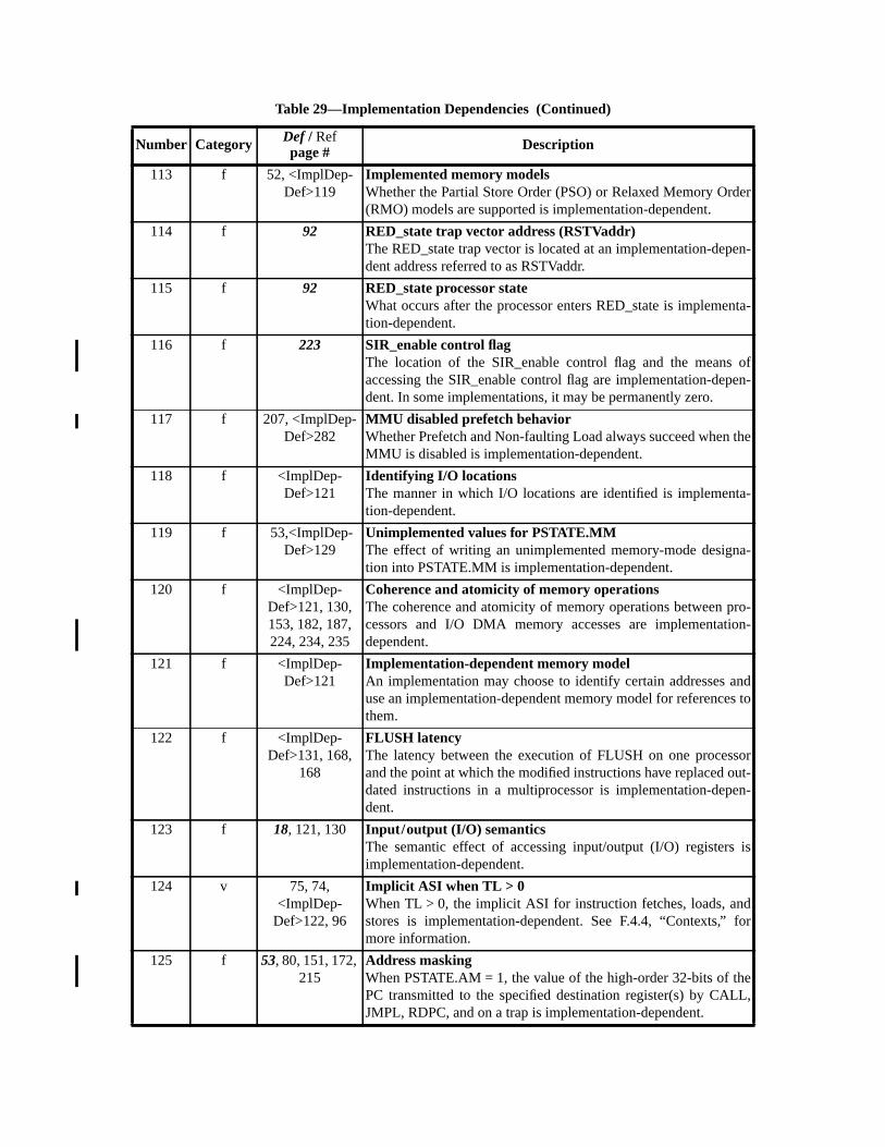
113 f 52, <ImplDep-Def>119
Implemented memory modelsWhether the Partial Store Order (PSO) or Relaxed Memory Order(RMO) models are supported is implementation-dependent.
114 f 92 RED_state trap vector address (RSTVaddr)The RED_state trap vector is located at an implementation-depen-dent address referred to as RSTVaddr.
115 f 92 RED_state processor stateWhat occurs after the processor enters RED_state is implementa-tion-dependent.
116 f 223 SIR_enable control flagThe location of the SIR_enable control flag and the means ofaccessing the SIR_enable control flag are implementation-depen-dent. In some implementations, it may be permanently zero.
117 f 207, <ImplDep-Def>282
MMU disabled prefetch behaviorWhether Prefetch and Non-faulting Load always succeed when theMMU is disabled is implementation-dependent.
118 f <ImplDep-Def>121
Identifying I/O locationsThe manner in which I/O locations are identified is implementa-tion-dependent.
119 f 53,<ImplDep-Def>129
Unimplemented values for PSTATE.MMThe effect of writing an unimplemented memory-mode designa-tion into PSTATE.MM is implementation-dependent.
120 f <ImplDep-Def>121, 130,153, 182, 187,224, 234, 235
Coherence and atomicity of memory operationsThe coherence and atomicity of memory operations between pro-cessors and I/O DMA memory accesses are implementation-dependent.
121 f <ImplDep-Def>121
Implementation-dependent memory modelAn implementation may choose to identify certain addresses anduse an implementation-dependent memory model for references tothem.
122 f <ImplDep-Def>131, 168,
168
FLUSH latencyThe latency between the execution of FLUSH on one processorand the point at which the modified instructions have replaced out-dated instructions in a multiprocessor is implementation-depen-dent.
123 f 18, 121, 130 Input/output (I/O) semanticsThe semantic effect of accessing input/output (I/O) registers isimplementation-dependent.
124 v 75, 74,<ImplDep-
Def>122, 96
Implicit ASI when TL > 0When TL > 0, the implicit ASI for instruction fetches, loads, andstores is implementation-dependent. See F.4.4, “Contexts,” formore information.
125 f 53, 80, 151, 172,215
Address maskingWhen PSTATE.AM = 1, the value of the high-order 32-bits of thePC transmitted to the specified destination register(s) by CALL,JMPL, RDPC, and on a trap is implementation-dependent.
Table 29—Implementation Dependencies (Continued)
Number Category Def / Refpage # Description
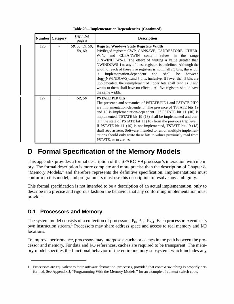
mem-ter 8,
musty.
ly tomust
snd I/O
o-e mem-s any
erly per-.
D Formal Specification of the Memory ModelsThis appendix provides a formal description of the SPARC-V9 processor’s interaction with ory. The formal description is more complete and more precise than the description of Chap“Memory Models,” and therefore represents the definitive specification. Implementationsconform to this model, and programmers must use this description to resolve any ambiguit
This formal specification is not intended to be a description of an actual implementation, ondescribe in a precise and rigorous fashion the behavior that any conforming implementationprovide.
D.1 Processors and Memory
The system model consists of a collection of processors, P0, P1,..Pn-1. Each processor executes itown instruction stream.1 Processors may share address space and access to real memory alocations.
To improve performance, processors may interpose acacheor caches in the path between the prcessor and memory. For data and I/O references, caches are required to be transparent. Thory model specifies the functional behavior of the entire memory subsystem, which include
126 v 58, 58, 59, 59,59, 60
Register Windows State Registers WidthPrivileged registers CWP, CANSAVE, CANRESTORE, OTHER-WIN, and CLEANWIN contain values in the range0..NWINDOWS-1. The effect of writing a value greater thanNWINDOWS-1 to any of these registers is undefined.Although thewidth of each of these five registers is nominally 5 bits, the widthis implementation-dependent and shall be betweenlog2(NWINDOWS) and 5 bits, inclusive. If fewer than 5 bits areimplemented, the unimplemented upper bits shall read as 0 andwrites to them shall have no effect. All five registers should havethe same width.
127 f 52, 56 PSTATE PID bitsThe presence and semantics of PSTATE.PID1 and PSTATE.PID0are implementation-dependent. The presence of TSTATE bits 19and 18 is implementation-dependent. If PSTATE bit 11 (10) isimplemented, TSTATE bit 19 (18) shall be implemented and con-tain the state of PSTATE bit 11 (10) from the previous trap level..If PSTATE bit 11 (10) is not implemented, TSTATE bit 19 (18)shall read as zero. Software intended to run on multiple implemen-tations should only write these bits to values previously read fromPSTATE, or to zeroes.
1. Processors are equivalent to their software abstraction, processes, provided that context switching is propformed. See Appendix J, “Programming With the Memory Models,” for an example of context switch code
Table 29—Implementation Dependencies (Continued)
Number Category Def / Refpage # Description

chieve
requireLUSHd dataO oper-
mem-sinceorder.der of
e pro-emory
tions and
ely
ialcts of
rocess
te toing con-instruc-es on
omicsuch ase ofem-
ion,e
form of caching. Implementations must use appropriate cache coherency mechanisms to athis transparency.1
The SPARC-V9 memory model requires that all data references be consistent but does notthat instruction references or input/output references be maintained consistent. The Finstruction or an appropriate operating system call may be used to ensure that instruction anspaces are consistent. Likewise, system software is needed to manage the consistency of I/ations.
The memory model is a local property of a processor that determines the order properties ofory references. The ordering properties have global implications when memory is shared,the memory model determines what data is visible to observing processors and in whatMoreover, the operative memory model of the observing processor affects the apparent orshared data reads and writes that it observes.
D.2 An Overview of the Memory Model Specification
The underlying goal of the memory model is to place the weakest possible constraints on thcessor implementations and to provide a precise specification of the possible orderings of moperations so that shared-memory multiprocessors can be constructed.
An execution traceis a sequence of instructions with a specified initial instruction. An executrace constitutes one possible execution of a program and may involve arbitrary reorderingparallel execution of instructions. Aself-consistentexecution trace is one that generates precisthe same results as those produced by a program order execution trace.
A program order execution trace is an execution trace that begins with a specified initinstruction and executes one instruction at a time in such a fashion that all the semantic effeeach instruction take effect before the next instruction is begun. The execution trace this pgenerates is defined to beprogram order.
A program is defined by the collection of all possible program order execution traces.
Dependence orderis a partial order on the instructions in an execution trace that is adequaensure that the execution trace is self-consistent. Dependence order can be constructed usventional data dependence analysis techniques. Dependence order holds only betweentions in the instruction trace of a single processor; instructions that are part of execution tracdifferent processors are never dependence-ordered.
Memory order is a total order on the memory reference instructions (loads, stores, and atload/stores) which satisfies the dependence order and, possibly, other order constraintsthose introduced implicitly by the choice of memory model or explicitly by the appearancmemory barrier (MEMBAR) instructions in the execution trace. The existence of a global mory order on the performance of all stores implies that memory access is write-atomic.2
1. Philip Bitar and Alvin M. Despain, “Multiprocessor Cache Synchronization: Issues, Innovations, Evolut”Proc. 13th Annual International Symposium on Computer Architecture, Computer Architecture News 14:2, Jun1986, pp.424-433.
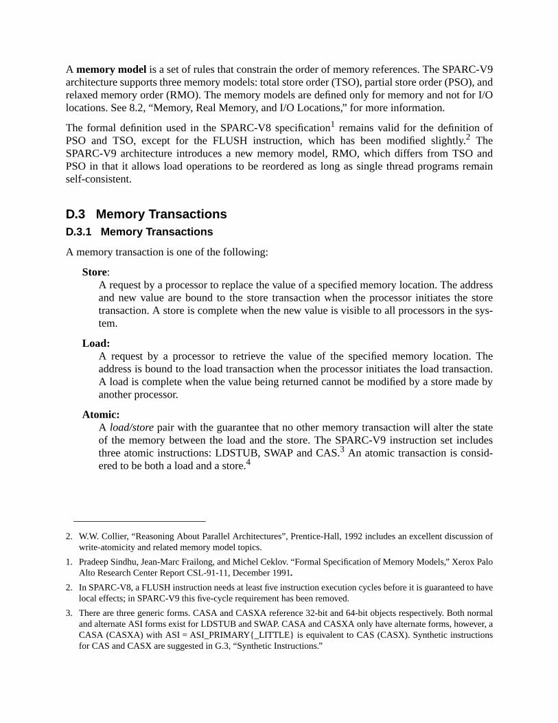
-V9), and
r I/O
andemain
dressstoresys-
Theaction.de by
tateludes
ion of
Palo
o have
ormaler, a
A memory model is a set of rules that constrain the order of memory references. The SPARCarchitecture supports three memory models: total store order (TSO), partial store order (PSOrelaxed memory order (RMO). The memory models are defined only for memory and not folocations. See 8.2, “Memory, Real Memory, and I/O Locations,” for more information.
The formal definition used in the SPARC-V8 specification1 remains valid for the definition ofPSO and TSO, except for the FLUSH instruction, which has been modified slightly.2 TheSPARC-V9 architecture introduces a new memory model, RMO, which differs from TSOPSO in that it allows load operations to be reordered as long as single thread programs rself-consistent.
D.3 Memory TransactionsD.3.1 Memory Transactions
A memory transaction is one of the following:
Store:A request by a processor to replace the value of a specified memory location. The adand new value are bound to the store transaction when the processor initiates thetransaction. A store is complete when the new value is visible to all processors in thetem.
Load:A request by a processor to retrieve the value of the specified memory location.address is bound to the load transaction when the processor initiates the load transA load is complete when the value being returned cannot be modified by a store maanother processor.
Atomic:A load/storepair with the guarantee that no other memory transaction will alter the sof the memory between the load and the store. The SPARC-V9 instruction set incthree atomic instructions: LDSTUB, SWAP and CAS.3 An atomic transaction is consid-ered to be both a load and a store.4
2. W.W. Collier, “Reasoning About Parallel Architectures”, Prentice-Hall, 1992 includes an excellent discusswrite-atomicity and related memory model topics.
1. Pradeep Sindhu, Jean-Marc Frailong, and Michel Ceklov. “Formal Specification of Memory Models,” XeroxAlto Research Center Report CSL-91-11, December 1991.
2. In SPARC-V8, a FLUSH instruction needs at least five instruction execution cycles before it is guaranteed tlocal effects; in SPARC-V9 this five-cycle requirement has been removed.
3. There are three generic forms. CASA and CASXA reference 32-bit and 64-bit objects respectively. Both nand alternate ASI forms exist for LDSTUB and SWAP. CASA and CASXA only have alternate forms, howevCASA (CASXA) with ASI = ASI_PRIMARY{_LITTLE} is equivalent to CAS (CASX). Synthetic instructionsfor CAS and CASX are suggested in G.3, “Synthetic Instructions.”

spaceemory
yeci-te
boveons
ssor
re
oces-
ct to
a bit-
tions
re thee scope
ther itlreadye store
lationecify
n an I/Oel level
Flush:A request by a processor to force changes in the data space aliased to the instructionto become consistent. Flush transactions are considered to be store operations for mmodel purposes.
Memory transactions are referred to by capital letters:Xna, which denotes a specific memortransactionX by processorn to memory addressa. The processor index and the address are spfied only if needed. The predicateS(X)is true if and only ifX has store semantics. The predicaL(X) is true if and only ifX has load semantics.
MEMBAR instructions are not memory transactions; rather they convey order information aand beyond the implicit ordering implied by the memory model in use. MEMBAR instructiare applied in program order.
D.3.2 Program Order
Theprogram order is a per-processor total order that denotes the sequence in which procenlogically executes instructions. The program order relation is denoted by<p such thatXn <p Yn istrue if and only if the memory transactionXn is caused by an instruction that is executed befothe instruction that caused memory transactionYn.
Program order specifies a unique total order for all memory transactions initiated by one prsor.
Memory barrier (MEMBAR) instructions executed by the processor are ordered with respe<p. The predicateM(X,Y) is true if and only ifX <p Y and there exists a MEMBAR instructionthat ordersX andY (that is, it appears in program order betweenX andY).MEMBAR instructionscan be either ordering or sequencing and may be combined into a single instruction usingencoded mask.1
Ordering MEMBAR instructions impose constraints on the order in which memory transacare performed.
Sequencing MEMBARs introduce additional constraints that are required in cases whememory transaction has side-effects beyond storing data. Such side-effects are beyond thof the memory model, which is limited to order and value semantics for memory.2
4. Even though the store part of a CASA is conditional, it is assumed that the store will always take place whedoes or not in a particular implementation. Since the value stored when the condition fails is the value apresent, and since the CASA operation is atomic, no observing processor can determine whether thoccurred or not.
1. The Ordering MEMBAR instruction uses 4 bits of its argument to specify the existence of an order redepending on whetherX andYhave load or store semantics. The Sequencing MEMBAR uses three bits to spcompletion conditions. The MEMBAR encoding is specified in A.32.
2. Sequencing constraints have other effects, such as controlling when a memory error is recognized or wheaccess reaches global visibility. The need for sequencing constraints is always associated with I/O and kernprogramming and not usually with normal, user-level application programming.
ory
uctionsoncur-mically
instruc-
s. Inh will
em-branchControle pre-
rderingr
s andsomeing a
on andr load-ct free,
dwarely, bya pro-ctionneces-
This definition of program order is equivalent to the definition given in the SPARC-V8 memmodel specification.
D.3.3 Dependence Order
Dependence order is a partial order that captures the constraints that hold between instrthat access the same processor register or memory location. In order to allow maximum crency in processor implementations, dependence order assumes that registers are dynarenamed to avoid false dependences arising from register reuse.
Two memory transactionX andY are dependence ordered, denoted byX <d Y, if and only if theyare program ordered,X <p Y , and at least one of the following conditions is true:
(1) The execution ofY is conditional onX, and S(Y) is true.
(2) Y reads a register that is written byX.
(3) X and Y access the same memory location andS(X) andL(Y) are both true.
The dependence order also holds between the memory transactions associated with thetions. It is important to remember that partial ordering is transitive.
Rule (1) includes all control dependences that arise from the dynamic execution of programparticular, a store or atomic memory transaction that is executed after a conditional brancdepend on the outcome of that branch instruction, which in turn will depend on one or more mory transactions that precede the branch instruction. Loads after an unresolved conditionalmay proceed, that is, a conditional branch does not dependence order subsequent loads.dependences always order the initiation of subsequent instructions to the performance of thceding instructions.1
Rule (2) captures dependences arising from register use. It is not necessary to include an owhenX reads a register that is later written byY, because register renaming will allow out-of-ordeexecution in this case. Register renaming is equivalent to having an infinite pool of registerrequiring all registers to be write-once. Observe that the condition code register is set byarithmetic and logical instructions and used by conditional branch instructions thus introducdependence order.
Rule (3) captures ordering constraints resulting from memory accesses to the same locatirequire that the dependence order reflect the program order for store-load pairs, but not fostore or store-store pairs. A load may be executed speculatively, since loads are side-effeprovided that Rule (3) is eventually satisfied.
An actual processor implementation will maintain dependence order by score-boarding, harinterlocks, data flow techniques, compiler directed code scheduling, and so forth, or, simpsequential program execution. The means by which the dependence order is derived fromgram is irrelevant to the memory model, which has to specify which possible memory transasequences are legal for a given set of data dependences. Practical implementations will not
1. Self modifying code (use of FLUSH instructions) also causes control dependences.

gramorrect-
semory
itrarilydiffer-
s the
otally
uires
trans-emoryseman-
sarily use the minimal set of constraints: adding unnecessary order relations from the proorder to the dependence order only reduces the available concurrency, but does not impair cness.
D.3.4 Memory Order
The sequence in which memory transactions are performed by the memory is calledmemoryorder, which is a total order on all memory transactions.
In general, the memory order cannot be knowna priori. Instead, the memory order is specified aa set of constraints that are imposed on the memory transactions. The requirement that mtransactionX must be performed before memory transactionY is denoted byX <m Y.Any mem-ory order that satisfies these constraints is legal. The memory subsystem may choose arbamong legal memory orders, hence multiple executions of the same programs may result inent memory orders.
D.4 Specification of Relaxed Memory Order (RMO)
D.4.1 Value Atomicity
Memory transactions will atomically set or retrieve the value of a memory location as long asize of the value is less than or equal to eight bytes, the unit of coherency.
D.4.2 Store Atomicity
All possible execution traces are consistent with the existence of a memory order that torders all transactions including all store operations.
This does not imply that the memory order is observable. Nor does it imply that RMO reqany central serialization mechanism.
D.4.3 Atomic Memory Transactions
The atomic memory transactions SWAP, LDSTUB, and CAS are performed as one memoryaction that is both a load and a store with respect to memory order constraints. No other mtransaction can separate the load and store actions of an atomic memory transaction. Thetics of atomic instructions are defined in Appendix A, “Instruction Definitions.”
D.4.4 Memory Order Constraints
A memory order is legal in RMO if and only if:
(1) X <d Y & L(X)⇒ X <m Y
(2) M(X,Y)⇒ X <m Y
(3) Xa <p Ya & S(Y)⇒ X <m Y
on is aserved
cessary
ct toing
hereed byby anytween
ARC-
thatcom-
is con-ionsruction
they an
Rule (1) states that the RMO model will maintain dependence when the preceding transactiload. Preceding stores may be delayed in the implementation, so their order may not be preglobally.
Rule (2) states that MEMBAR instructions order the performance of memory transactions.
Rule (3) states that stores to the same address are performed in program order. This is nefor processor self-consistency
D.4.5 Value of Memory Transactions
The value of a loadYa is the value of the most recent store that was performed with respememory order or the value of the most recently initiated store by the same processor. AssumYis a load to memory locationa:
Value(La) = Value( Max<m { S | Sa <m La or Sa <p La } )
whereMax<m{..} selects the most recent element with respect to the memory order and wValue()yields the value of a particular memory transaction. This states that the value returna load is either the result of the most recent store to that address which has been performedprocessor or which has been initiated by the processor issuing the load. The distinction belocal and remote stores permits use of store-buffers, which are explicitly supported in all SPV9 memory models.
D.4.6 Termination of Memory Transactions
Any memory transaction will eventually be performed. This is formalized by the requirementonly a finite number of memory ordered loads can be performed before a pending store ispleted.
D.4.7 Flush Memory Transaction
Flush instructions are treated as store memory transactions as far as the memory ordercerned. Their semantics are defined in A.20, “Flush Instruction Memory.” Flush instructintroduce a control dependence to any subsequent (in program order) execution of the instthat was addressed by the flush.
D.5 Specification of Partial Store Order (PSO)
The specification of Partial Store Order (PSO) is that of Relaxed Memory Order (RMO) withadditional requirement that all memory transactions with load semantics are followed bimplied MEMBAR #LoadLoad | #LoadStore .

ddi-plied
cutionf ordereferred
fromes to the0.
issued
r
cebeen
mbarcan be
ratess about
able (nt tocode
omitted
D.6 Specification of Total Store Order (TSO)
The specification of Total Store Order (TSO) is that of Partial Store Order (PSO) with the ational requirement that all memory transactions with store semantics are followed by an imMEMBAR #StoreStore .
D.7 Examples Of Program Executions
This subsection lists several code sequences and an exhaustive list of all possible exesequences under RMO, PSO and TSO. For each example, the code is followed by the list orelations between the corresponding memory transactions. The memory transactions are rto by numbers. In each case, the program is executed once for each memory model.
D.7.1 Observation of Store Atomicity
The code example below demonstrates how store atomicity prevents multiple processorsobserving inconsistent sequences of events. In this case, processors 2 and 3 observe changshared variablesA andB, which are being modified by processor 1. Initially both variables areThe stores by processor 1 do not use any form of synchronization, and they may in fact beby two independent processors.
Should processor 2 findA to have the new value (1) andB to have the old value (0), it can infethatA was updated beforeB. Likewise, processor 3 may findB = 1 andA = 0, which implies thatB was changed beforeA. It is impossible for both to occur in all SPARC-V9 memory models sinthere cannot exist a total order on all stores. This property of the memory models hasencoded in the assertion A1.
However, in RMO, the observing processor must separate the load operations with meinstructions. Otherwise, the loads may be reordered and no inference on the update ordermade.
Figure 44 is taken from the output of the SPARC-V9 memory model simulator, which enumeall possible outcomes of short code sequences and which can be used to prove assertionsuch programs.
D.7.2 Dekker’s Algorithm
The essence of Dekker’s algorithm is shown in figure 45 on page 298.1 To assure mutual exclu-sion, each processor signals its intent to enter a critical region by asserting a dedicated variAfor processor 1 andB for processor 2). It then checks that the other processor does not waenter and, if it finds the other signal variable is deasserted, it enters the critical region. Thisdoes not guarantee that any processor can enter (that requires a retry mechanism which is
1. See also DEC Litmus Test 8 described in theAlpha Architecture Handbook, Digital Equipment Corporation,1992, p. 5-14.
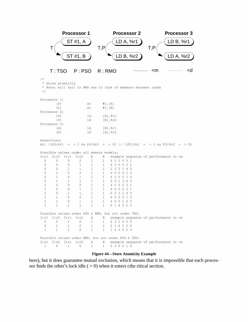
roces-
here), but it does guarantee mutual exclusion, which means that it is impossible that each psor finds the other’s lock idle ( = 0) when it enters cthe ritical section.ST #1, A
ST #1, B
LD A, %r1
LD B, %r2
LD B, %r1
LD A, %r2
T T,P T,P
T : TSO P : PSO R : RMO <d<m
Processor 1 Processor 2 Processor 3
/* * Store atomicity * Note: will fail in RMO due to lack of membars between loads */
Processor 1: (0) st #1,[A] (1) st #1,[B]Processor 2: (2) ld [A],%r1 (3) ld [B],%r2Processor 3: (4) ld [B],%r1 (5) ld [A],%r2
Assertions:A1: !(P2:%r1 = = 1 && P2:%r2 = = 0) || !(P3:%r1 = = 1 && P3:%r2 = = 0)
Possible values under all memory models:2:r1 2:r2 3:r1 3:r2 A B example sequence of performance in <m 0 0 0 0 1 1 4 5 2 0 3 1 0 0 0 1 1 1 4 2 0 5 3 1 0 0 1 1 1 1 2 3 0 1 4 5 0 1 0 0 1 1 4 5 2 0 1 3 0 1 0 1 1 1 4 2 0 5 1 3 0 1 1 1 1 1 2 0 1 3 4 5 1 0 0 0 1 1 4 5 0 2 3 1 1 0 0 1 1 1 4 0 5 2 3 1 1 0 1 1 1 1 0 2 3 1 4 5 1 1 0 0 1 1 4 5 0 2 1 3 1 1 0 1 1 1 4 0 5 1 2 3 1 1 1 1 1 1 0 1 4 2 5 3
Possible values under PSO & RMO, but not under TSO:2:r1 2:r2 3:r1 3:r2 A B example sequence of performance in <m 0 0 1 0 1 1 2 3 1 4 5 0 0 1 1 0 1 1 2 1 4 3 5 0 1 1 1 0 1 1 1 4 5 0 2 3
Possible values under RMO, but not under PSO & TSO:2:r1 2:r2 3:r1 3:r2 A B example sequence of performance in <m 1 0 1 0 1 1 5 3 0 2 1 4
Figure 44—Store Atomicity Example

erved,ssor 3impact
), theorder.
s by a
D.7.3 Indirection Through Processors
Another property of the SPARC-V9 memory models is that causal update relations are preswhich is a side-effect of the existence of a total memory order. In the example below, proceobserves updates made by processor 1. Processor 2 simply copies B to C, which does notthe causal chain of events.
Again, this example intentionally exposes two potential error sources. In PSO (and RMOstores by processor 1 are not ordered automatically and may be performed out of programThe correct code would need to insert a MEMBAR#StoreStore between these stores. InRMO (but not in PSO), the observation process 3 needs to separate the two load instructionMEMBAR #LoadLoad .
ST #1, A
LD B, %r1
ST #1, B
LD A, %r1T,P,R T,P,R
Processor 1 Processor 2
/* * Dekker's Algorithm */Processor 1: (0) st #1,[A] membar #StoreLoad (1) ld [B],%r1Processor 2: (2) st #1,[B] membar #StoreLoad (3) ld [A],%r1
Assertions:A1: P1:%r1 = = 1 || P2:%r1 = = 1
Possible values under all memory models:1:r1 2:r1 A B example sequence of performance in <m 0 1 1 1 0 1 2 3 1 0 1 1 2 3 0 1 1 1 1 1 2 0 3 1
Possible values under PSO & RMO, but not under TSO: --- none ---
Possible values under RMO, but not under PSO & TSO: --- none ---
T : TSO P : PSO R : RMO <d<m
Figure 45—Dekker’s Algorithm

out ofper-, then
pilerodel
D.7.4 PSO Behavior
The code in figure 47 on page 300 shows how different results can be obtained by allowingorder performance of two stores in PSO and RMO models. A store to B is allowed to beformed before a store to A. If two loads of processor 2 are performed between the two storesthe assertion below is satisfied for the PSO and RMO models.
D.7.5 Application to Compilers
A significant problem in a multiprocessor environment arises from the fact that normal comoptimizations which reorder code can subvert programmer intent. The SPARC-V9 memory m
ST #1, A
ST #1, B
LD B, %r1
ST %r1, C
LD C, %r1
LD A, %r2T T,PT,P,R
Processor 1 Processor 2 Processor 3
T : TSO P : PSO R : RMO <d<m/* * Indirection through processors * Note: Assertion will fail for PSO and RMO due to lack of * membar #StoreStore after P1's first store */Processor 1: (0) st #1,[A] (1) st #1,[B]Processor 2: (2) ld [B],%r1 (3) st %r1,[C]Processor 3: (4) ld [C],%r1 (5) ld [A],%r2
Assertions:A1: !(P3:%r1 = = 1 && P3:%r2 = = 0)
Possible values under all memory models:2:r1 3:r1 3:r2 A B C example sequence of performance in <m 0 0 0 1 1 0 4 5 0 2 1 3 0 0 1 1 1 0 4 2 0 5 1 3 1 0 0 1 1 1 4 5 0 1 2 3 1 0 1 1 1 1 4 0 5 1 2 3 1 1 1 1 1 1 0 1 2 3 4 5
Possible values under PSO & RMO, but not under TSO:2:r1 3:r1 3:r2 A B C example sequence of performance in <m 1 1 0 1 1 1 1 2 3 4 5 0
Possible values under RMO, but not under PSO & TSO: --- none ---
Figure 46—Indirection Through Processors
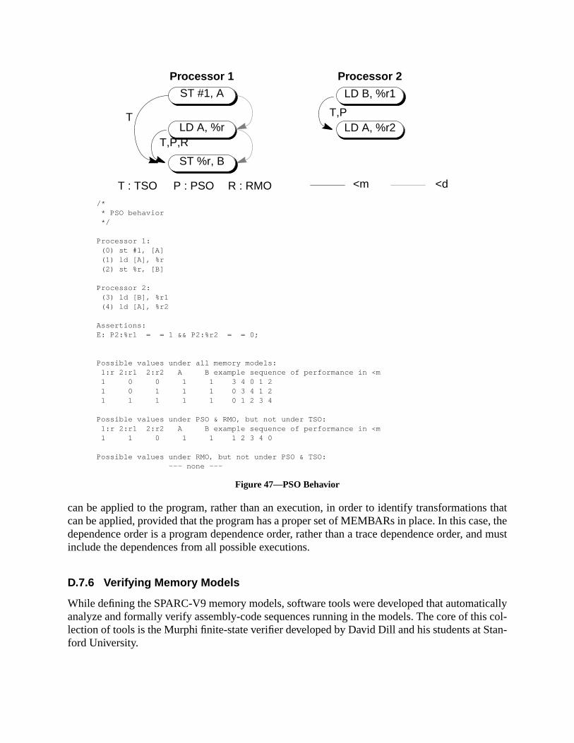
s thate, the
and must
icallyis col-tan-
can be applied to the program, rather than an execution, in order to identify transformationcan be applied, provided that the program has a proper set of MEMBARs in place. In this casdependence order is a program dependence order, rather than a trace dependence order,include the dependences from all possible executions.
D.7.6 Verifying Memory Models
While defining the SPARC-V9 memory models, software tools were developed that automatanalyze and formally verify assembly-code sequences running in the models. The core of thlection of tools is the Murphi finite-state verifier developed by David Dill and his students at Sford University.
ST #1, A
LD A, %r
LD B, %r1
LD A, %r2T,P
ST %r, B
T
T,P,R
Processor 1 Processor 2
T : TSO P : PSO R : RMO <d<m
/* * PSO behavior */
Processor 1: (0) st #1, [A] (1) ld [A], %r (2) st %r, [B]
Processor 2: (3) ld [B], %r1 (4) ld [A], %r2
Assertions:E: P2:%r1 = = 1 && P2:%r2 = = 0;
Possible values under all memory models: 1:r 2:r1 2:r2 A B example sequence of performance in <m 1 0 0 1 1 3 4 0 1 2 1 0 1 1 1 0 3 4 1 2 1 1 1 1 1 0 1 2 3 4
Possible values under PSO & RMO, but not under TSO: 1:r 2:r1 2:r2 A B example sequence of performance in <m 1 1 0 1 1 1 2 3 4 0
Possible values under RMO, but not under PSO & TSO: --- none ---
Figure 47—PSO Behavior

erly inork bynly bending
k, and:
For example, these tools can be used to confirm that synchronization routines operate propvarious memory models and to generate counter example traces when they fail. The tools wexhaustively enumerating system states in a version of the memory model, so they can oapplied to fairly small assembly code examples. We found the tools to be helpful in understathe memory models and checking our examples.1
Contact SPARC International to obtain the verification tools and a set of examples.
1. For a discussion of an earlier application of similar tools to TSO and PSO, see David Dill, Seungjoon ParAndreas G. Nowatzyk, “Formal Specification of Abstract Memory Models” inResearch on Integrated SystemsProceedings of the 1993 Symposium, Ed. Gaetano Borriello and Carl Ebeling, MIT Press, 1993.

e shall6.3.11,
withn pageuction
E Opcode Maps
E.1 Overview
This appendix contains the SPARC-V9 instruction opcode maps.
Opcodes marked with a dash ‘—’ are reserved; an attempt to execute a reserved opcodcause a trap, unless it is an implementation-specific extension to the instruction set. See“Reserved Opcodes and Instruction Fields,” for more information.
In this appendix and in Appendix A, “Instruction Definitions,” certain opcodes are markedmnemonic superscripts. These superscripts and their meanings are defined in table 21 o133. For deprecated opcodes, see the appropriate instruction pages in Appendix A, “InstrDefinitions,” for preferred substitute instructions.
E.2 Tables
†rd = 0, imm22 = 0
Table 30—op[1:0]
op [1:0]
0 1 2 3
Branches & SETHISee table 31
CALL Arithmetic & Misc.See table 32
Loads/StoresSee table 33
Table 31—op2[2:0] (op= 0)
op2 [2:0]
0 1 2 3 4 5 6 7
ILLTRAPBPcc
See table 42BiccD
See table 42BPr
See table 43SETHINOP†
FBPfccSee table 42
FBfccD
See table 42—
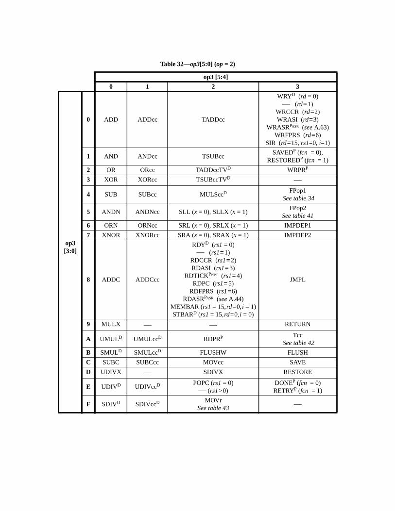
Table 32—op3[5:0] (op= 2)
op3 [5:4]
0 1 2 3
op3[3:0]
0 ADD ADDcc TADDcc
WRYD (rd = 0)— (rd= 1)
WRCCR (rd=2)WRASI (rd=3)
WRASRPASR (seeA.63)WRFPRS (rd=6)
SIR (rd=15, rs1=0, i=1)
1 AND ANDcc TSUBccSAVEDP (fcn = 0),
RESTOREDP (fcn = 1)
2 OR ORcc TADDccTVD WRPRP
3 XOR XORcc TSUBccTVD —
4 SUB SUBcc MULSccDFPop1
See table 34
5 ANDN ANDNcc SLL (x = 0), SLLX (x = 1)FPop2
See table 41
6 ORN ORNcc SRL (x = 0), SRLX (x = 1) IMPDEP1
7 XNOR XNORcc SRA (x = 0), SRAX (x = 1) IMPDEP2
8 ADDC ADDCcc
RDYD (rs1= 0)— (rs1= 1)
RDCCR (rs1= 2)RDASI (rs1= 3)
RDTICKPNPT (rs1= 4)RDPC (rs1= 5)
RDFPRS (rs1=6)RDASRPASR (seeA.44)
MEMBAR (rs1= 15,rd=0,i = 1)STBARD (rs1= 15,rd=0,i = 0)
JMPL
9 MULX — — RETURN
A UMULD UMULccD RDPRP TccSee table 42
B SMULD SMULccD FLUSHW FLUSH
C SUBC SUBCcc MOVcc SAVE
D UDIVX — SDIVX RESTORE
E UDIVD UDIVccD POPC (rs1= 0)— (rs1>0)
DONEP (fcn = 0)RETRYP (fcn = 1)
F SDIVD SDIVccD MOVrSee table 43
—

Table 33—op3[5:0] (op= 3)
op3 [5:4]
0 1 2 3
op3[3:0]
0 LDUW LDUWA PASI LDF LDFAPASI
1 LDUB LDUBA PASI LDFSRD, LDXFSR —2 LDUH LDUHA PASI LDQF LDQFAPASI
3 LDDD LDDAD, PASI LDDF LDDFAPASI
4 STW STWAPASI STF STFAPASI
5 STB STBAPASI STFSRD, STXFSR —6 STH STHAPASI STQF STQFAPASI
7 STDD STDAPASI STDF STDFAPASI
8 LDSW LDSWAPASI — —9 LDSB LDSBAPASI — —A LDSH LDSHAPASI — —B LDX LDXA PASI — —C — — — CASAPASI
D LDSTUB LDSTUBAPASI PREFETCH PREFETCHAPASI
E STX STXAPASI — CASXAPASI
F SWAPD SWAPAD, PASI — —
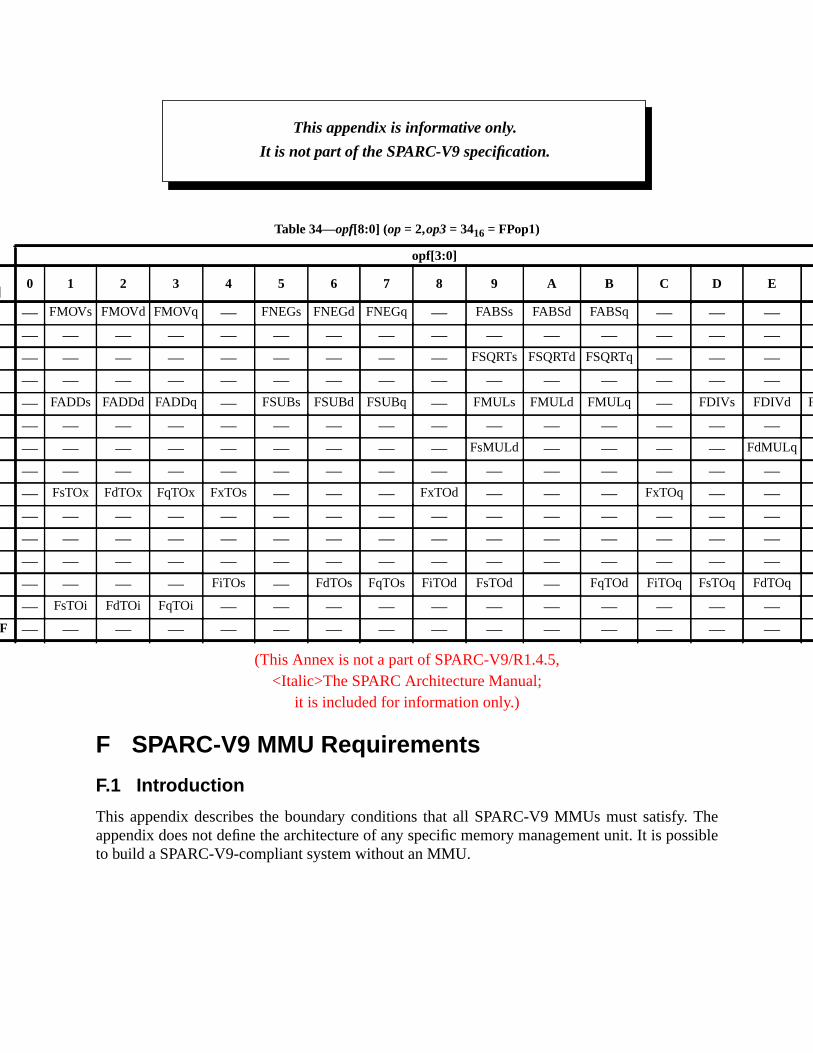
Thessible
opf[8:4]
0 1 E F
00 — FMOV — —01 — — — —02 — — — —03 — — — —04 — FADD FDIVd FDIVq
05 — — — —06 — — FdMULq —07 — — — —08 — FsTO — —09 — — — —0A — — — —0B — — — —0C — — q FdTOq —0D — FsTO — —
0E..1F — — — —
(This Annex is not a part of SPARC-V9/R1.4.5,<Italic>The SPARC Architecture Manual;
it is included for information only.)
F SPARC-V9 MMU Requirements
F.1 Introduction
This appendix describes the boundary conditions that all SPARC-V9 MMUs must satisfy.appendix does not define the architecture of any specific memory management unit. It is poto build a SPARC-V9-compliant system without an MMU.
Table 34—opf[8:0] (op= 2,op3= 3416 = FPop1)
opf[3:0]
2 3 4 5 6 7 8 9 A B C D
s FMOVd FMOVq — FNEGs FNEGd FNEGq — FABSs FABSd FABSq — —
— — — — — — — — — — — —
— — — — — — — FSQRTs FSQRTd FSQRTq — —
— — — — — — — — — — — —s FADDd FADDq — FSUBs FSUBd FSUBq — FMULs FMULd FMULq — FDIVs
— — — — — — — — — — — —
— — — — — — — FsMULd — — — —
— — — — — — — — — — — —x FdTOx FqTOx FxTOs — — — FxTOd — — — FxTOq —
— — — — — — — — — — — —
— — — — — — — — — — — —
— — — — — — — — — — — —
— — FiTOs — FdTOs FqTOs FiTOd FsTOd — FqTOd FiTOq FsTO
i FdTOi FqTOi — — — — — — — — — —
— — — — — — — — — — — —
This appendix is informative only.
It is not part of the SPARC-V9 specification.

s may
dress.
e of as maybutes
imple-
ion
(see.3,
both
tion.and
ces as
F.1.1 Definitions
address space:A range of locations accessible with a 64-bit virtual address. Different address spaceuse the same virtual address to refer to different physical locations.
aliases:Two virtual addresses are aliases of each other if they refer to the same physical ad
context:A set of translations used to support a particular address space.
page:The range of virtual addresses translated by a single translation element. The sizpage is the size of the range translated by a single translation element. Different pagehave different sizes. Associated with a page or with a translation element are attri(e.g., restricted, permission, etc.) and statistics (e.g., referenced, modified, etc.)
translation element:Used to translate a range of virtual addresses to a range of physical addresses.
F.2 Overview
All SPARC-V9 MMUs must provide the following basic functions:
— Translate 64-bit virtual addresses to physical addresses. This translation may bemented with one or more page sizes.
— Provide the RED_state operation, as defined in 7.2.1, “RED_state.”
— Provide a method for disabling the MMU. When the MMU is disabled, no translatoccurs: Physical Address<N:0> = Virtual Address<N:0>, whereN is implementation-dependent. Furthermore, the disabled MMU will not perform any memory protectionF.4.2, “Memory Protection”) or prefetch and non-faulting load violation (see F.4“Prefetch and Non-Faulting Load Violation”) checks.
IMPL. DEP. #117: Whether PREFETCH and non-faulting load always succeed when the MMU isdisabled is implementation-dependent.
— Provide page-level protections. Conventional protections (Read, Write, Execute) forprivileged and nonprivileged accesses may be provided.
— Provide page-level enabling and disabling of prefetch and non-faulting load operaThe MMU, however, need not provide separate protection mechanisms for prefetchnon-faulting load.
— Support multiple address spaces (ASIs). The MMU must support the address spadefined in F.3.1, “Information the MMU Expects from the Processor.”
— Provide page-level statistics such as referenced and modified.
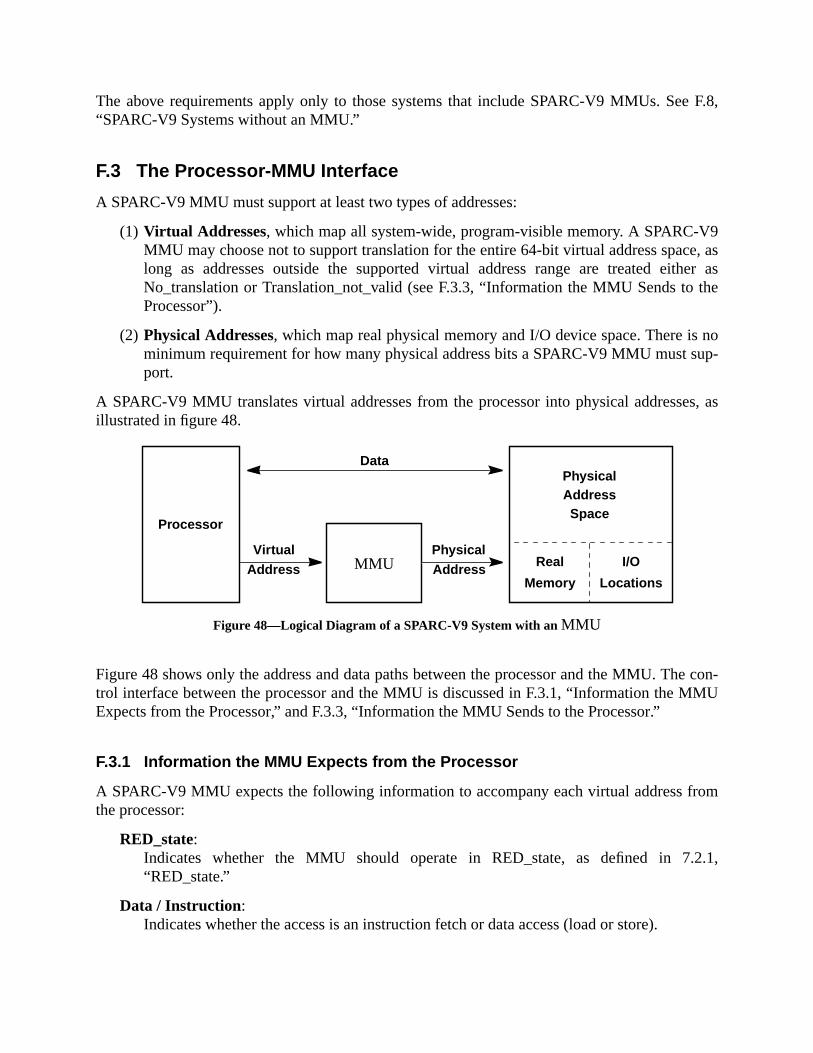
e F.8,
9e, asther asthe
noup-
es, as
he con-MU
rom
.2.1,
The above requirements apply only to those systems that include SPARC-V9 MMUs. Se“SPARC-V9 Systems without an MMU.”
F.3 The Processor-MMU Interface
A SPARC-V9 MMU must support at least two types of addresses:
(1) Virtual Addresses, which map all system-wide, program-visible memory. A SPARC-VMMU may choose not to support translation for the entire 64-bit virtual address spaclong as addresses outside the supported virtual address range are treated eiNo_translation or Translation_not_valid (see F.3.3, “Information the MMU Sends toProcessor”).
(2) Physical Addresses, which map real physical memory and I/O device space. There isminimum requirement for how many physical address bits a SPARC-V9 MMU must sport.
A SPARC-V9 MMU translates virtual addresses from the processor into physical addressillustrated in figure 48.
Figure 48—Logical Diagram of a SPARC-V9 System with anMMU
Figure 48 shows only the address and data paths between the processor and the MMU. Ttrol interface between the processor and the MMU is discussed in F.3.1, “Information the MExpects from the Processor,” and F.3.3, “Information the MMU Sends to the Processor.”
F.3.1 Information the MMU Expects from the Processor
A SPARC-V9 MMU expects the following information to accompany each virtual address fthe processor:
RED_state:Indicates whether the MMU should operate in RED_state, as defined in 7“RED_state.”
Data / Instruction:Indicates whether the access is an instruction fetch or data access (load or store).
I/O
Locations
Processor
Physical
MMU
Address
VirtualAddress
PhysicalAddress
Data
Space
Real
Memory

of the
(data
d, the
r the
storeslemen-h the
the
ap-s. Write
ission isis-
ute
cationation
with
etch-ads
Prefetch:Indicates whether the data (Data / Instruction = Data) access was initiated by oneSPARC-V9 prefetch instructions.
Privileged:Indicates whether this access is privileged.
Read / Write:Indicates whether this access is a read (instruction fetch or data load) or a writestore) operation.
Atomic:Indicates whether this is an atomic load-store operation. Whenever atomic is assertevalue of “Read/Write” is treated by the MMU as “don’t care.”
ASI:An 8-bit address space identifier. See 6.3.1.3, “Address Space Identifiers (ASIs),” folist of ASIs that the MMU must support.
F.3.2 Attributes the MMU Associates with Each Mapping
In addition to translating virtual addresses to physical addresses, a SPARC-V9 MMU alsoassociated attributes, either with each mapping or with each page, depending upon the imptation. Some of these attributes may be associated implicitly, as opposed to explicitly, witmapping. This information includes
Restricted:Only privileged accesses are allowed (see F.3.1, “Information the MMU Expects fromProcessor”); nonprivileged accesses are disallowed.
Read, Write, and Execute Permissions:An MMU may allow zero or more of read, write, and execute permissions, on a per-mping basis. Read permission is necessary for data read accesses and atomic accessepermission is necessary for data write accesses and atomic accesses. Execute permnecessary for instruction accesses. At a minimum, an MMU must allow for “all permsions,” “no permissions,” and “no write permission”; optionally, it can provide “execonly” and “write only,” or any combination of “read/write/execute” permissions.
Prefetchable:The presence of this attribute indicates that accesses made with the prefetch indifrom the processor are allowed; otherwise, they are disallowed. See F.3.1, “Informthe MMU Expects from the Processor.”
Non-faultable:The presence of this attribute indicates that accesses madeASI_PRIMARY_NOFAULT{_LITTLE} andASI_SECONDARY_NOFAULT{_LITTLE} are allowed;otherwise, they are disallowed. An implementation may choose to combine the prefable and non-faultable attributes into a single “No Side Effects” attribute; that is, “refrom this address do not cause side effects, such as clear on read.”

C-V9
. Can
omely
tion.tion.
n theects
, orssion,
dis-
hich
of the
F.3.3 Information the MMU Sends to the Processor
The processor can expect one and only one of the following signals coming from any SPARMMU for each translation requested:
Translation_error :The MMU has detected an error (for example, parity error) in the translation processcause adata_access_error or instruction_access_error exception.
No_translation:The MMU is unable to translate the virtual address, since no translation exists for it. Simplementations may not provide this information and provide onTranslation_not_valid. Can cause either adata_access_exception or aninstruction_access_exception exception.
Translation_not_valid:The MMU is unable to translate the virtual address, since it cannot find a valid translaSome implementations may not provide this information and provide only No_translaCan cause either adata_access_MMU_miss or an instruction_access_MMU_miss exception.
Privilege_violation:The MMU has detected a privilege violation, i.e., an access to a restricted page wheaccess does not have the required privilege (see F.3.1, “Information the MMU Expfrom the Processor”). Can cause either adata_access_protection or aninstruction_access_protection exception.
Protection_violation:The MMU has detected a protection violation, which is defined to be a read, writeinstruction fetch attempt to a page that does not have read, write, or execute permirespectively. Can cause either adata_access_protection or an instruction_access_protectionexception.
Prefetch_violation:The MMU has detected an attempt to prefetch from a page for which prefetching isabled.
NF-Load_violation:The MMU has detected an attempt to perform a non-faulting load from a page for wnon-faulting loads are disabled.
Translation_successful:The MMU has successfully translated the virtual address to a physical address; noneconditions described above has been detected.
F.4 Components of the SPARC-V9 MMU Architecture
A SPARC-V9 MMU should contain the following:
— Logic that implements virtual-to-physical address translation
nate
ces
ss as
Data/r a
ondi-coun-tion, orr.”
MU
icted
rans-
that
g as
em-
— Logic that provides memory protection
— Logic that supports prefetching as noted in A.42, “Prefetch Data”
— Logic that supports non-faulting loading, as noted in 8.3, “Addressing and AlterAddress Spaces”
— A method for specifying the primary, secondary and, optionally, nucleus address spa
— A method for supplying information related to failed translations
— A method for collecting “referenced” and “modified” statistics
F.4.1 Virtual-to-Physical Address Translation
A SPARC-V9 MMU tries to translate every virtual address it receives into a physical addrelong as:
— The MMU is enabled.
— The processor indicates that this is a non-RED_state instruction fetch (see theInstruction description in F.3.1, “Information the MMU Expects from the Processor”) odata access with an ASI that indicates a translatable address space.
Although the MMU will attempt to translate every virtual address that meets the above two ctions, it need not guarantee that it can provide a translation every time. When the MMU enters a virtual address that it cannot translate, it asserts either Translation_error, No_translaTranslation_not_valid, as discussed in F.3.3, “Information the MMU Sends to the Processo
F.4.2 Memory Protection
For each virtual address for which a SPARC-V9 MMU can provide a translation, the Mchecks whether memory protection would be violated. More specifically, the MMU
— Indicates Privilege_violation (see F.3.3) if the translation information indicates a restrpage but the access was not privileged (see F.3.1)
— Indicates Protection_violation (see F.3.3) if a read, write, or instruction fetch uses a tlation that does not grant read, write, or execute permission, respectively
— Indicates Protection_violation (see F.3.3) if an atomic load-store uses a translationdoes not grant both read and write permission
F.4.3 Prefetch and Non-Faulting Load Violation
For each virtual address, the MMU checks for prefetch or non-faulting load violation as lon
— The MMU can provide a translation, and
— The MMU does not detect any memory protection violation, as discussed in F.4.2, “Mory Protection.”

the
F.3.1)
non-
eld, asde, itugh
More specifically, the MMU performs the following before sending the physical address torest of the memory system:
— Asserts Prefetch_violation (see F.3.3) if an access with the prefetch indication (seeuses a translation that lacks the prefetchable attribute (see F.3.2)
— Asserts NF-Load_violation (see F.3.3) if the ASI (see F.3.1) indicates this access is afaulting load, but the translation it uses lacks the non-faultable attribute (see F.3.2)
F.4.4 Contexts
The MMU must support two contexts:
(1) Primary Context
(2) Secondary Context
In addition, it is also recommended that the MMU support a third context:
(3) Nucleus Context
On data accesss, the MMU decides which of these three contexts to use based on the ASI fiillustrated in table 35. Because the SPARC-V9 MMU cannot determine the instruction opcotreats all data accesses with ASI_PRIMARY{_LITTLE} as normal loads or stores, even thothe processor may issue them with load/store alternate instructions.
† Support for the nucleus context is only a recommendation; if an implementation does not support thenucleus context it may ignore this row.
Table 35—Context Used for Data Access
MMU Inputs OutputContextASI Mode
ASI_PRIMARY Either Primary
ASI_PRIMARY_LITTLE Either Primary
ASI_PRIMARY_NOFAULT Either Primary
ASI_PRIMARY_NOFAULT_LITTLE Either Primary
ASI_AS_IF_USER_PRIMARY Privileged Primary
ASI_AS_IF_USER_PRIMARY_LITTLE Privileged Primary
ASI_SECONDARY Either Secondary
ASI_SECONDARY_LITTLE Either Secondary
ASI_SECONDARY_NOFAULT Either Secondary
ASI_SECONDARY_NOFAULT_LITTLE Either Secondary
ASI_AS_IF_USER_SECONDARY Privileged Secondary
ASI_AS_IF_USER_SECONDARY_LITTLE Privileged Secondary
ASI_NUCLEUS † Privileged Nucleus
ASI_NUCLEUS_LITTLE † Privileged Nucleus

rated
thend anyp; for
struc-not
reof,d/ornced, athat a
nslation
dated
U is
led.es the
On instruction fetch, the MMU decides which context to use based on the ASI field, as illustin table 36. Note that the secondary context is never used for instruction fetch.
† Support for the Nucleus Context is only a recommendation; if an implementation does not support theNucleus Context it may ignore this row.
‡ It is implementation-dependent whether instruction fetch using ASI_NUCLEUS in nonprivilegedmode is allowed.
F.4.5 Fault Status and Fault Address
A SPARC-V9 MMU must provide the following:
— Fault status information that specifies which condition listed in F.3.3, “InformationMMU Sends to the Processor,” has resulted in a translation-related processor trap, aother information necessary for privileged software to determine the cause of the traexample, ASI, Read/Write, Data/Instruction, etc.
— The Fault address associated with the failed translation. Since the address from an intion translation failure is available in the processor as the trap PC, the MMU isrequired to save the address of an instruction translation failure.
F.4.6 Referenced and Modified Statistics
A SPARC-V9 MMU shall allow, either through hardware, software, or some combination thefor the collection of “referenced” and “modified” statistics associated with translations anphysical pages. That is, there must be a method to determine if a page has been referemethod to determine if a page has been modified, and a method for clearing the indicationspage has been referenced and/or modified. These statistics may be kept on either a per-trabasis or a per-physical-page basis.
It is implementation-dependent whether the referenced and/or modified statistics are upwhen an access is performed or when the translation for that access is performed.
F.5 RED_state Processing
It is recommended that the MMU perform as follows when the processor is in RED_state:
— Instruction address translation is a straight-through physical map; that is, the MMalways suppressed for instruction access in RED_state.
— Data address translation is handled normally; that is, the MMU is used if it is enabNote that any event which causes the processor to enter RED_state also disablMMU, however, the handler executing in RED_state may reenable the MMU.
Table 36—Context Used for Instruction Access
ASI Mode Context
ASI_PRIMARY Either Primary
ASI_NUCLEUS† Privileged‡ Nucleus

to theribed ining
t con-given
e or
hould
inor thatescrip-
for the
C-V9
F.6 Virtual Address Aliasing
Hardware and privileged software must cooperate so that multiple virtual addresses aliasedsame physical address appear to be consistent as defined by the memory models descChapter 8, “Memory Models.” Depending upon the implementation, this may require allowmultiple translations to coexist only if they meet some implementation-dependent alignmenstraint, or it may require that software ensure that only one translation is in effect at anytime.
F.7 MMU Demap Operation
The SPARC-V9 MMU must provide a mechanism for privileged software to invalidate somall of the virtual-to-physical address translations.
F.8 SPARC-V9 Systems without an MMU
It is possible to build a SPARC-V9 system that does not have an MMU. Such a system sbehave as if contains an MMU that is disabled.
(This Annex is not a part of SPARC-V9/R1.4.5,<Italic>The SPARC Architecture Manual;
it is included for information only.)
G Suggested Assembly Language SyntaxThis appendix supports Appendix A, “Instruction Definitions.” Each instruction descriptionAppendix A includes a table that describes the suggested assembly language format finstruction. This appendix describes the notation used in those assembly language syntax dtions and lists some synthetic instructions that may be provided by a SPARC-V9 assemblerconvenience of assembly language programmers.
G.1 Notation Used
The notations defined here are also used in the syntax descriptions in Appendix A.
Items intypewriter font are literals to be written exactly as they appear. Items initalic fontare metasymbols that are to be replaced by numeric or symbolic values in actual SPAR
This appendix is informative only.
It is not part of the SPARC-V9 specification.

0a
binaryhe
e fol-
ne of
es:
ne of
assembly language code. For example, “imm_asi” would be replaced by a number in the rangeto 255 (the value of theimm_asibits in the binary instruction), or by a symbol bound to suchnumber.
Subscripts on metasymbols further identify the placement of the operand in the generatedinstruction. For example,regrs2 is a reg (register name) whose binary value will be placed in trs2 field of the resulting instruction.
G.1.1 Register Names
reg:A reg is an integer register name. It may have any of the following values:1
%r0 ..%r31
%g0..%g7 (global registers; same as%r0 ..%r7)%o0..%o7 (out registers; same as%r8 ..%r15)%l0 ..%l7 (local registers; same as%r16 ..%r23)%i0 ..%i7 (in registers; same as%r24 ..%r31)%fp (frame pointer; conventionally same as%i6 )%sp (stack pointer; conventionally same as%o6)
Subscripts identify the placement of the operand in the binary instruction as one of thlowing:
regrs1 (rs1 field)regrs2 (rs2 field)regrd (rd field)
freg:An freg is a floating-point register name. It may have the following values:
%f0, %f1, %f2 .. %f63 See 5.1.4, “Floating-Point Registers”
Subscripts further identify the placement of the operand in the binary instruction as othe following:
fregrs1 (rs1 field)fregrs2 (rs2 field)fregrd (rd field)
asr_reg:An asr_reg is an Ancillary State Register name. It may have one of the following valu
%asr16 ..%asr31
Subscripts further identify the placement of the operand in the binary instruction as othe following:
asr_regrs1 (rs1 field)asr_regrd (rd field)
1.In actual usage, the%sp, %fp, %gn, %on, %ln, and%in forms are preferred over%rn.
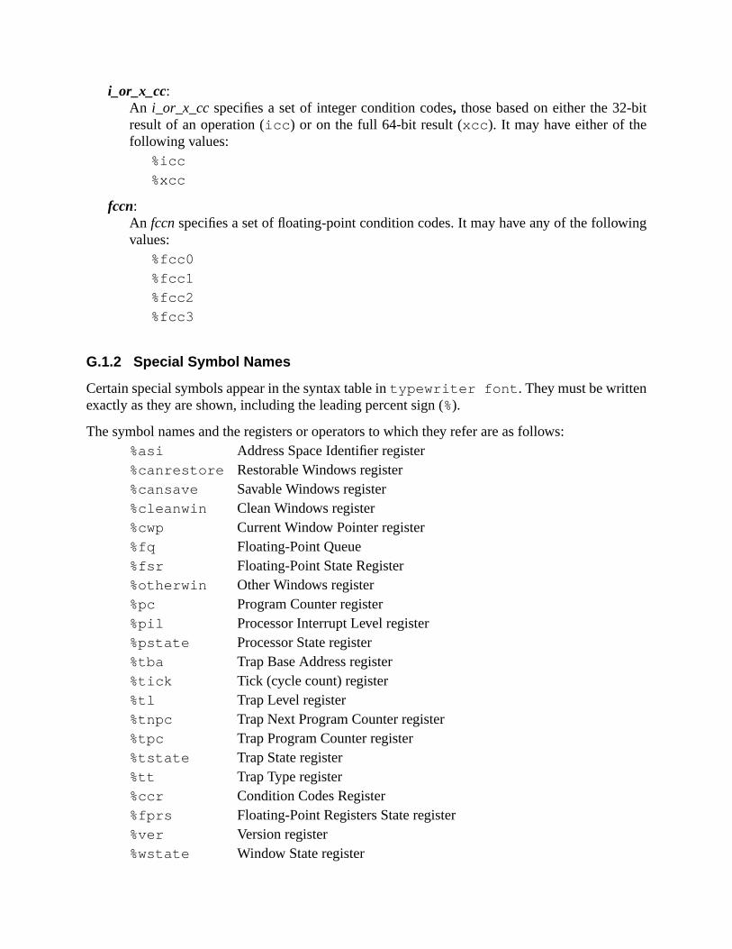
it
ing
i_or_x_cc:An i_or_x_ccspecifies a set of integer condition codes, those based on either the 32-bresult of an operation (icc ) or on the full 64-bit result (xcc ). It may have either of thefollowing values:
%icc
%xcc
fccn:An fccnspecifies a set of floating-point condition codes. It may have any of the followvalues:
%fcc0
%fcc1
%fcc2
%fcc3
G.1.2 Special Symbol Names
Certain special symbols appear in the syntax table intypewriter font . They must be writtenexactly as they are shown, including the leading percent sign (%).
The symbol names and the registers or operators to which they refer are as follows:%asi Address Space Identifier register%canrestore Restorable Windows register%cansave Savable Windows register%cleanwin Clean Windows register%cwp Current Window Pointer register%fq Floating-Point Queue%fsr Floating-Point State Register%otherwin Other Windows register%pc Program Counter register%pil Processor Interrupt Level register%pstate Processor State register%tba Trap Base Address register%tick Tick (cycle count) register%tl Trap Level register%tnpc Trap Next Program Counter register%tpc Trap Program Counter register%tstate Trap State register%tt Trap Type register%ccr Condition Codes Register%fprs Floating-Point Registers State register%ver Version register%wstate Window State register

ed:
r-
%y Y register
The following special symbol names are unary operators that perform the functions describ%uhi Extracts bits 63..42 (high 22 bits of upper word) of its operand%ulo Extracts bits 41..32 (low-order 10 bits of upper word) of its operand%hi Extracts bits 31..10 (high-order 22 bits of low-order word) of its ope
and%lo Extracts bits 9..0 (low-order 10 bits) of its operand
Certain predefined value names appear in the syntax table intypewriter font . They must bewritten exactly as they are shown, including the leading sharp sign (#).
The value names and the values to which they refer are as follows:#n_reads 0 (for PREFETCH instruction)#one_read 1 (for PREFETCH instruction)#n_writes 2 (for PREFETCH instruction)#one_write 3 (for PREFETCH instruction)#page 4 (for PREFETCH instruction)#Sync 4016 (for MEMBAR instructioncmask field)#MemIssue 2016 (for MEMBAR instructioncmask field)#Lookaside 1016 (for MEMBAR instructioncmask field)#StoreStore 0816 (for MEMBAR instructionmmask field)#LoadStore 0416 (for MEMBAR instructionmmask field)#StoreLoad 0216 (for MEMBAR instructionmmask field)#LoadLoad 0116 (for MEMBAR instructionmmask field)#ASI_AIUP 1016 ASI_AS_IF_USER_PRIMARY#ASI_AIUS 1116 ASI_AS_IF_USER_SECONDARY#ASI_AIUP_L 1816 ASI_AS_IF_USER_PRIMARY_LITTLE#ASI_AIUS_L 1916 ASI_AS_IF_USER_SECONDARY_LITTLE#ASI_P 8016 ASI_PRIMARY#ASI_S 8116 ASI_SECONDARY#ASI_PNF 8216 ASI_PRIMARY_NOFAULT#ASI_SNF 8316 ASI_SECONDARY_NOFAULT#ASI_P_L 8816 ASI_PRIMARY_LITTLE#ASI_S_L 8916 ASI_SECONDARY_LITTLE#ASI_PNF_L 8A16 ASI_PRIMARY_NOFAULT_LITTLE#ASI_SNF_L 8B16 ASI_SECONDARY_NOFAULT_LITTLE
The full names of the ASIs may also be defined:#ASI_AS_IF_USER_PRIMARY 1016
#ASI_AS_IF_USER_SECONDARY 1116
#ASI_AS_IF_USER_PRIMARY_LITTLE 1816
#ASI_AS_IF_USER_SECONDARY_LITTLE1916

er and9). Anly.
#ASI_PRIMARY 8016
#ASI_SECONDARY 8116
#ASI_PRIMARY_NOFAULT 8216
#ASI_SECONDARY_NOFAULT 8316
#ASI_PRIMARY_LITTLE 8816
#ASI_SECONDARY_LITTLE 8916
#ASI_PRIMARY_NOFAULT_LITTLE 8A16
#ASI_SECONDARY_NOFAULT_LITTLE 8B16
G.1.3 Values
Some instructions use operand values as follows:const4 A constant that can be represented in 4 bitsconst22 A constant that can be represented in 22 bitsimm_asi An alternate address space identifier (0..255)simm7 A signed immediate constant that can be represented in 7 bitssimm10 A signed immediate constant that can be represented in 10 bitssimm11 A signed immediate constant that can be represented in 11 bitssimm13 A signed immediate constant that can be represented in 13 bitsvalue Any 64-bit valueshcnt32 A shift count from 0..31shcnt64 A shift count from 0..63
G.1.4 Labels
A label is a sequence of characters that comprises alphabetic letters (a–z, A–Z [with upplower case distinct]), underscores (_), dollar signs ($), periods (.), and decimal digits (0-label may contain decimal digits, but may not begin with one. A local label contains digits o
G.1.5 Other Operand Syntax
Some instructions allow several operand syntaxes, as follows:
reg_plus_imm may be any of the following:regrs1 (equivalent toregrs1 + %g0)regrs1+ simm13regrs1 – simm13simm13 (equivalent to%g0 + simm13)simm13+ regrs1 (equivalent toregrs1 + simm13)
address may be any of the following:regrs1 (equivalent toregrs1 + %g0)regrs1+ simm13

res-
regrs1 – simm13simm13 (equivalent to%g0 + simm13)simm13+ regrs1 (equivalent toregrs1 + simm13)regrs1+ regrs2
membar_mask is the following:const7 A constant that can be represented in 7 bits. Typically, this is an exp
sion involving the logicalor of some combination of#Lookaside ,#MemIssue , #Sync , #StoreStore , #LoadStore , #Store-Load , and#LoadLoad .
prefetch_fcn (prefetch function) may be any of the following:#n_reads
#one_read
#n_writes
#one_write
#page
0..31
regaddr (register-only address) may be any of the following:regrs1 (equivalent toregrs1 + %g0)regrs1+ regrs2
reg_or_imm (register or immediate value) may be either of:regrs2simm13
reg_or_imm10 (register or immediate value) may be either of:regrs2simm10
reg_or_imm11 (register or immediate value) may be either of:regrs2simm11
reg_or_shcnt (register or shift count value) may be any of:regrs2shcnt32shcnt64
software_trap_number may be any of the following:regrs1 (equivalent toregrs1 + %g0)regrs1+ simm7regrs1 – simm7simm7 (equivalent to%g0 + simm7)simm7+ regrs1 (equivalent toregrs1 + simm7)

usive.
yle “
nd in
,
is
struc-or the
pro-lwaystions.
regrs1+ regrs2
The resulting operand value (software trap number) must be in the range 0..127, incl
G.1.6 Comments
It is suggested that two types of comments be accepted by SPARC-V9 assemblers: C-st/*...*/ ” comments, which may span multiple lines, and “!... ” comments, which extend fromthe “! ” to the end of the line.
G.2 Syntax Design
The suggested SPARC-V9 assembly language syntax is designed so that
— The destination operand (if any) is consistently specified as the last (rightmost) operaan assembly language instruction.
— A reference to thecontents of a memory location (in a Load, Store, CASA, CASXALDSTUB(A), or SWAP(A) instruction) is always indicated by square brackets([]); a ref-erence to theaddressof a memory location (such as in a JMPL, CALL, or SETHI)specified directly, without square brackets.
G.3 Synthetic Instructions
Table 37 describes the mapping of a set of synthetic (or “pseudo”) instructions to actual intions. These and other synthetic instructions may be provided in a SPARC-V9 assembler fconvenience of assembly language programmers.
Note that synthetic instructions should not be confused with “pseudo-ops,” which typicallyvide information to the assembler but do not generate instructions. Synthetic instructions agenerate instructions; they provide more mnemonic syntax for standard SPARC-V9 instruc
Table 37—Mapping Synthetic to SPARC-V9 Instructions
Synthetic instruction SPARC-V9 instruction(s) Comment
cmp regrs1, reg_or_imm subcc regrs1, reg_or_imm, %g0 compare
jmp address jmpl address, %g0
call address jmpl address, %o7
iprefetch label bn,a,pt %xcc, label instruction prefetch
tst regrs1 orcc %g0, regrs1, %g0 test
ret jmpl %i7+8, %g0 return from subroutine
retl jmpl %o7+8, %g0 return from leaf subroutine
restore restore %g0, %g0, %g0 trivial restore
save save %g0, %g0, %g0 trivial save(Warning: trivial saveshould only be used in kernelcode!)
set uw value, regrd sethi %hi (value ), regrd (when ((value&3FF16) = = 0))

— or —
or %g0, value, regrd (when 0≤value≤4095 )
— or —
sethi %hi (value), regrd; (otherwise)
or regrd, %lo (value), regrd Warning: do not usesetuw inthe delay slot of a DCTI.
set value, regrd synonym forsetuw
set sw value, regrd sethi %hi (value ), regrd (when (value> = 0) and((value & 3FF16) = = 0))
— or —
or %g0, value, regrd (when -4096≤value≤4095 )
— or —
sethi %hi (value ), regrd (otherwise, if (value < 0) and((value & 3FF16) = = 0))
sra regrd, %g0, regrd
— or —
sethi %hi (value), regrd; (otherwise, if value> = 0)
or regrd, %lo (value), regrd
— or —
sethi %hi (value), regrd; (otherwise, if value<0)
or regrd, %lo (value), regrd
sra regrd, %g0, regrd Warning: do not usesetsw inthe delay slot of a CTI.
setx value, reg, regrd sethi %uhi( value ), reg create 64-bit constant
or reg, %ulo( value), reg (“reg” is used as a temporaryregister)sllx reg,32, reg
sethi %hi( value), regrd Note:set x optimizations arepossible, but not enumer-ated here. The worst-case isshown.Warning: do not useset x in the delay slot of aCTI.
or regrd, reg, regrd
or regrd, %lo( value), regrd
Table 37—Mapping Synthetic to SPARC-V9 Instructions (Continued)
Synthetic instruction SPARC-V9 instruction(s) Comment
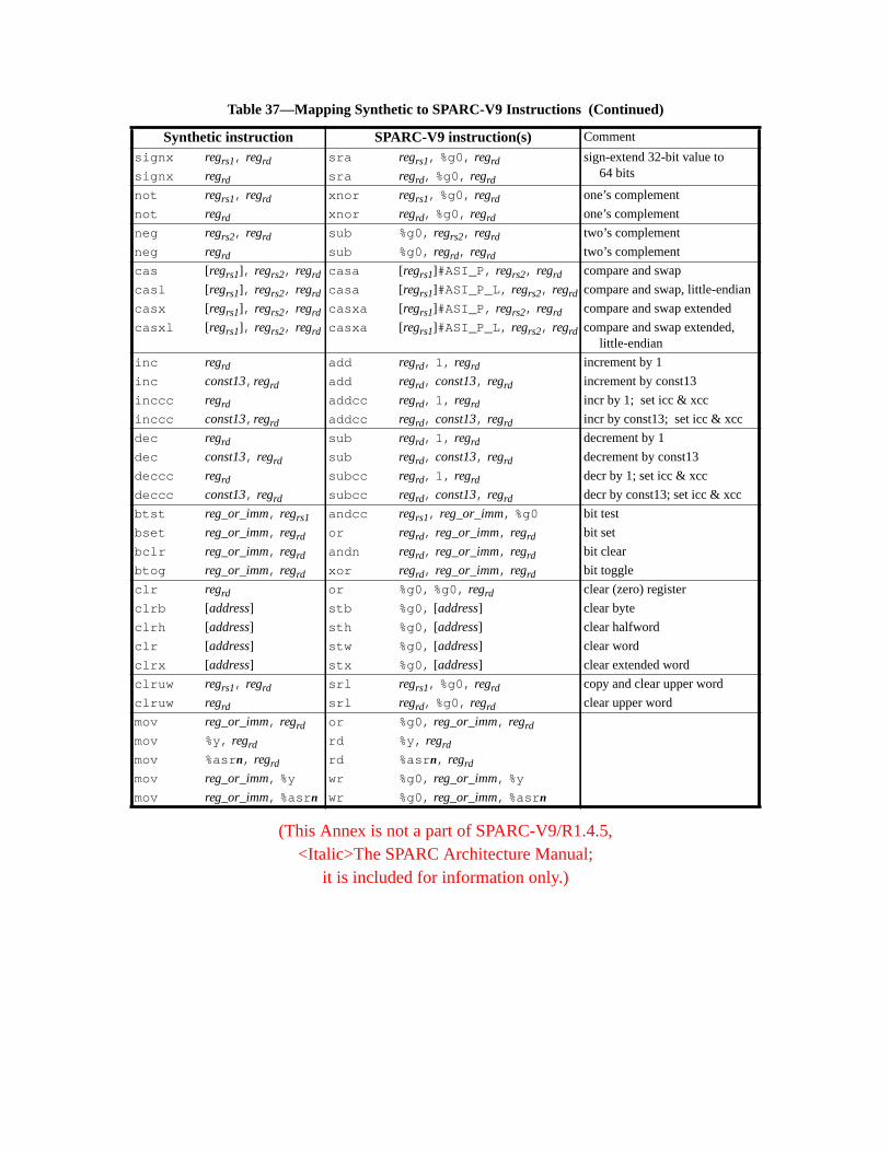
(This Annex is not a part of SPARC-V9/R1.4.5,<Italic>The SPARC Architecture Manual;
it is included for information only.)
signx regrs1, regrd sra regrs1, %g0, regrd sign-extend 32-bit value to64 bitssignx regrd sra regrd, %g0, regrd
not regrs1, regrd xnor regrs1, %g0, regrd one’s complement
not regrd xnor regrd, %g0, regrd one’s complement
neg regrs2, regrd sub %g0, regrs2, regrd two’s complement
neg regrd sub %g0, regrd, regrd two’s complement
cas [regrs1], regrs2, regrd casa [regrs1]#ASI_P, regrs2, regrd compare and swap
casl [regrs1], regrs2, regrd casa [regrs1]#ASI_P_L, regrs2, regrd compare and swap, little-endian
casx [regrs1], regrs2, regrd casxa [regrs1]#ASI_P, regrs2, regrd compare and swap extended
casxl [regrs1], regrs2, regrd casxa [regrs1]#ASI_P_L, regrs2, regrd compare and swap extended,little-endian
inc regrd add regrd, 1, regrd increment by 1
inc const13, regrd add regrd, const13, regrd increment by const13
inccc regrd addcc regrd, 1, regrd incr by 1; set icc & xcc
inccc const13, regrd addcc regrd, const13, regrd incr by const13; set icc & xcc
dec regrd sub regrd, 1, regrd decrement by 1
dec const13, regrd sub regrd, const13, regrd decrement by const13
deccc regrd subcc regrd, 1, regrd decr by 1; set icc & xcc
deccc const13, regrd subcc regrd, const13, regrd decr by const13; set icc & xcc
btst reg_or_imm, regrs1 andcc regrs1, reg_or_imm, %g0 bit test
bset reg_or_imm, regrd or regrd, reg_or_imm, regrd bit set
bclr reg_or_imm, regrd andn regrd, reg_or_imm, regrd bit clear
btog reg_or_imm, regrd xor regrd, reg_or_imm, regrd bit toggle
clr regrd or %g0, %g0, regrd clear (zero) register
clrb [address] stb %g0, [address] clear byte
clrh [address] sth %g0, [address] clear halfword
clr [address] stw %g0, [address] clear word
clrx [address] stx %g0, [address] clear extended word
clruw regrs1, regrd srl regrs1, %g0, regrd copy and clear upper word
clruw regrd srl regrd, %g0, regrd clear upper word
mov reg_or_imm, regrd or %g0, reg_or_imm, regrd
mov %y, regrd rd %y, regrd
mov %asrn, regrd rd %asr n, regrd
mov reg_or_imm, %y wr %g0, reg_or_imm, %y
mov reg_or_imm, %asr n wr %g0, reg_or_imm, %asr n
Table 37—Mapping Synthetic to SPARC-V9 Instructions (Continued)
Synthetic instruction SPARC-V9 instruction(s) Comment

mples
sump-thosearchi-
nven-
sub-
cturet
fromecutes
at anyf the
H Software ConsiderationsThis appendix describes how software can use the SPARC-V9 architecture effectively. Exado not necessarily conform to any specific Application Binary Interface (ABI).
H.1 Nonprivileged Software
This subsection describes software conventions that have proven or may prove useful, astions that compilers may make about the resources available, and how compilers can useresources. It does not discuss how supervisor software (an operating system) may use thetecture. Although a set of software conventions is described, software is free to use other cotions more appropriate for specific applications.
The following are the primary goals for many of the software conventions described in thissection:
— Minimizing average procedure-call overhead
— Minimizing latency due to branches
— Minimizing latency due to memory access
H.1.1 Registers
Register usage is a critical resource allocation issue for compilers. The SPARC-V9 architeprovides windowed integer registers (in, out, local), global integer registers, and floating-poinregisters.
H.1.1.1 In and Out Registers
The in andout registers are used primarily for passing parameters to and receiving resultssubroutines, and for keeping track of the memory stack. When a procedure is called and exa SAVE instruction, the caller’souts become the callee’sins.
One of a procedure’sout registers (%o6) is used as its stack pointer,%sp. It points to an area inwhich the system can store%r16 ..%r31 (%l0 ..%l7 and%i0 ..%i7 ) when the register file over-flows (spill trap), and is used to address most values located on the stack. A trap can occurtime1, which may precipitate a subsequent spill trap. During this spill trap, the contents ouser’s register window at the time of the original trap are spilled to the memory to which its%sppoints.
This appendix is informative only.
It is not part of the SPARC-V9 specification.

r
ed
e
ting
elay-
ncy,to the
han
han sixgram-ame-any of
a
aining
A procedure may store temporary values in itsout registers (except%sp) with the understandingthat those values are volatile across procedure calls.%spcannot be used for temporary values fothe reasons described in H.1.1.3, “Register Windows and %sp.”
Up to six parameters1 may be passed by placing them inout registers%o0..%o5; additionalparameters are passed in the memory stack. The stack pointer is implicitly passed in%o6, and aCALL instruction places its own address in%o7.2 Floating-point parameters may also be passin floating-point registers.
After a callee is entered and its SAVE instruction has been executed, the caller’sout registers areaccessible as the callee’sin registers.
The caller’s stack pointer%sp (%o6) automatically becomes the current procedure’s frampointer%fp (%i6 ) when the SAVE instruction is executed.
The callee finds its first six integer parameters in%i0 ..%i5 , and the remainder (if any) on thestack.
A function returns a scalar integer value by writing it into itsins (which are the caller’souts),starting with%i0 . A scalar floating-point value is returned in the floating-point registers, starwith %f0.
A procedure’s return address, normally the address of the instruction just after the CALL’s dslot instruction, is as%i7+8 .3
H.1.1.2 Local Registers
The locals are used for automatic4 variables and for most temporary values. For access efficiea compiler may also copy parameters (that is, those past the sixth) from the memory stack inlocals and use them from there.
See H.1.4, “Register Allocation within a Window,” for methods of allocating more or fewer teight registers for local values.
1. For example, due to an error in executing an instruction (for example, amem_address_not_aligned trap), or dueto any type of external interrupt.
1. Six is more than adequate, since the overwhelming majority of procedures in system code take fewer tparameters. According to studies cited by Weicker (Weicker, R. P., “Dhrystone: A Synthetic Systems Proming Benchmark,”CACM27:10, October 1984), at least 97% (measured statically) take fewer than six parters. The average number of parameters did not exceed 2.1, measured either statically or dynamically, inthese studies.
2. If a JMPL instruction is used in place of a CALL, it should place its address in%o7 for consistency.
3. For convenience, SPARC-V9 assemblers may provide a “ret ” (return) synthetic instruction that generates“ jmpl %i7+8 , %g0” hardware instruction. See G.3, “Synthetic Instructions.”
4. In the C language, an automatic variable is a local variable whose lifetime is no longer than that of its contprocedure.
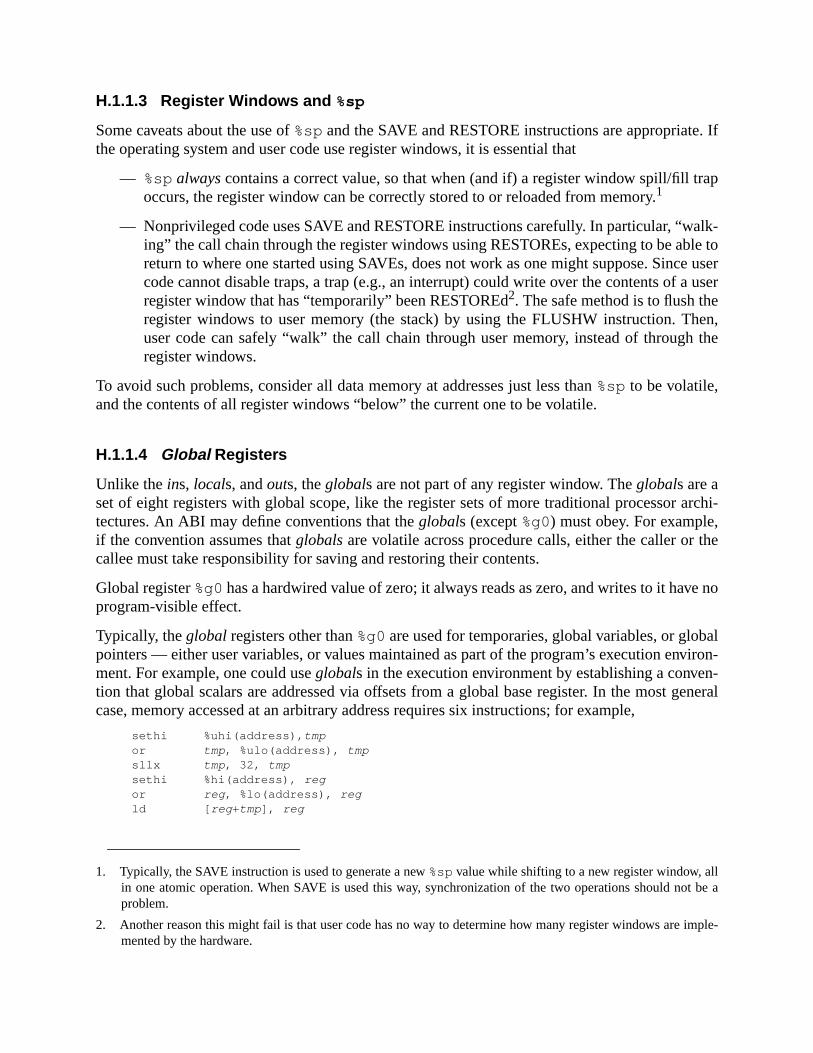
. If
rap
alk-le toe usera user
hen,the
archi-
the
e no
alviron-n-eneral
lt be a
imple-
H.1.1.3 Register Windows and %sp
Some caveats about the use of%spand the SAVE and RESTORE instructions are appropriatethe operating system and user code use register windows, it is essential that
— %spalwayscontains a correct value, so that when (and if) a register window spill/fill toccurs, the register window can be correctly stored to or reloaded from memory.1
— Nonprivileged code uses SAVE and RESTORE instructions carefully. In particular, “wing” the call chain through the register windows using RESTOREs, expecting to be abreturn to where one started using SAVEs, does not work as one might suppose. Sinccode cannot disable traps, a trap (e.g., an interrupt) could write over the contents ofregister window that has “temporarily” been RESTOREd2. The safe method is to flush theregister windows to user memory (the stack) by using the FLUSHW instruction. Tuser code can safely “walk” the call chain through user memory, instead of throughregister windows.
To avoid such problems, consider all data memory at addresses just less than%sp to be volatile,and the contents of all register windows “below” the current one to be volatile.
H.1.1.4 Global Registers
Unlike theins, locals, andouts, theglobals are not part of any register window. Theglobals are aset of eight registers with global scope, like the register sets of more traditional processortectures. An ABI may define conventions that theglobals (except%g0) must obey. For example,if the convention assumes thatglobalsare volatile across procedure calls, either the caller orcallee must take responsibility for saving and restoring their contents.
Global register%g0has a hardwired value of zero; it always reads as zero, and writes to it havprogram-visible effect.
Typically, theglobal registers other than%g0are used for temporaries, global variables, or globpointers — either user variables, or values maintained as part of the program’s execution enment. For example, one could useglobals in the execution environment by establishing a convetion that global scalars are addressed via offsets from a global base register. In the most gcase, memory accessed at an arbitrary address requires six instructions; for example,
sethi %uhi(address), tmpor tmp , %ulo(address), tmpsllx tmp , 32, tmpsethi %hi(address), regor reg , %lo(address), regld [ reg +tmp ], reg
1. Typically, the SAVE instruction is used to generate a new%spvalue while shifting to a new register window, alin one atomic operation. When SAVE is used this way, synchronization of the two operations should noproblem.
2. Another reason this might fail is that user code has no way to determine how many register windows aremented by the hardware.
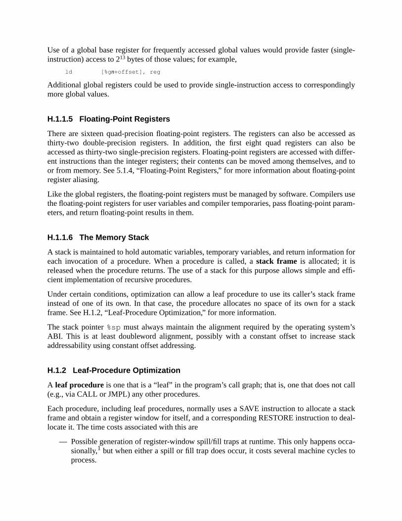
ingle-
ingly
ssed aso bediffer-
, and tooint
rs usearam-
n for
nd effi-
ramestack
m’stack
call
stackdeal-
cca-s to
Use of a global base register for frequently accessed global values would provide faster (sinstruction) access to 213 bytes of those values; for example,
ld [%g n+offset], reg
Additional global registers could be used to provide single-instruction access to correspondmore global values.
H.1.1.5 Floating-Point Registers
There are sixteen quad-precision floating-point registers. The registers can also be accethirty-two double-precision registers. In addition, the first eight quad registers can alsaccessed as thirty-two single-precision registers. Floating-point registers are accessed withent instructions than the integer registers; their contents can be moved among themselvesor from memory. See 5.1.4, “Floating-Point Registers,” for more information about floating-pregister aliasing.
Like the global registers, the floating-point registers must be managed by software. Compilethe floating-point registers for user variables and compiler temporaries, pass floating-point peters, and return floating-point results in them.
H.1.1.6 The Memory Stack
A stack is maintained to hold automatic variables, temporary variables, and return informatioeach invocation of a procedure. When a procedure is called, astack frame is allocated; it isreleased when the procedure returns. The use of a stack for this purpose allows simple acient implementation of recursive procedures.
Under certain conditions, optimization can allow a leaf procedure to use its caller’s stack finstead of one of its own. In that case, the procedure allocates no space of its own for aframe. See H.1.2, “Leaf-Procedure Optimization,” for more information.
The stack pointer%sp must always maintain the alignment required by the operating systeABI. This is at least doubleword alignment, possibly with a constant offset to increase saddressability using constant offset addressing.
H.1.2 Leaf-Procedure Optimization
A leaf procedure is one that is a “leaf” in the program’s call graph; that is, one that does not(e.g., via CALL or JMPL) any other procedures.
Each procedure, including leaf procedures, normally uses a SAVE instruction to allocate aframe and obtain a register window for itself, and a corresponding RESTORE instruction tolocate it. The time costs associated with this are
— Possible generation of register-window spill/fill traps at runtime. This only happens osionally,1 but when either a spill or fill trap does occur, it costs several machine cycleprocess.

f which
,of the
gis-
stackcalledits
s:
es vol-
oce-ed
t is
. Ifg
er win-
o per-
— The cycles expended by the SAVE and RESTORE instructions themselves.
There are also space costs associated with this convention, the cumulative cache effects omay be nonnegligible. The space costs include
— The space occupied on the stack by the procedure’s stack frame
— The two words occupied by the SAVE and RESTORE instructions
Of the above costs, the trap-processing cycles typically are the most significant.
Some leaf procedures can be made to operatewithout their own register window or stack frameusing their caller’s instead. This can be done when the candidate leaf procedure meets allfollowing conditions:1
— It contains no references to%sp, except in its SAVE instruction.
— It contains no references to%fp.
— It refers to (or can be made to refer to) no more than eight of the thirty-two integer reters, including%o7 (the return address).
If a procedure conforms to the above conditions, it can be made to operate using its caller’sframe and registers, an optimization that saves both time and space. This optimization isleaf procedure optimization. The optimized procedure may safely use only registers thatcaller already assumes to be volatile across a procedure call.
The optimization can be performed at the assembly language level using the following step
(1) Change all references to registers in the procedure to registers that the caller assumatile across the call.
(a) Leave references to%o7 unchanged.
(b) Leave any references to%g0..%g7 unchanged.
(c) Change%i0 ..%i5 to %o0..%o5, respectively. If anin register is changed to anoutregister that was already referenced in the original unoptimized version of the prdure, all original references to thatout register must be changed to refer to an unusout or global register.
(d) Change references to eachlocal register into references to any unused register thaassumed to be volatile across a procedure call.
(2) Delete the SAVE instruction. If it was in a delay slot, replace it with a NOP instructionits destination register was not%g0 or %sp, convert the SAVE into the correspondinADD instruction instead of deleting it.
1. The frequency of overflow and underflow traps depends on the application and on the number of registdows (NWINDOWS) implemented in hardware.
1. Although slightly less restrictive conditions could be used, the optimization would become more complex tform and the incremental gain would usually be small.
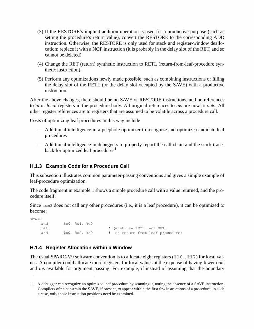
h asADDallo-d so
syn-
llingtive
rences
e call.
leaf
ace-
mple of
e pro-
ed to
rndary
ruction.such
(3) If the RESTORE’s implicit addition operation is used for a productive purpose (sucsetting the procedure’s return value), convert the RESTORE to the correspondinginstruction. Otherwise, the RESTORE is only used for stack and register-window decation; replace it with a NOP instruction (it is probably in the delay slot of the RET, ancannot be deleted).
(4) Change the RET (return) synthetic instruction to RETL (return-from-leaf-procedurethetic instruction).
(5) Perform any optimizations newly made possible, such as combining instructions or fithe delay slot of the RETL (or the delay slot occupied by the SAVE) with a producinstruction.
After the above changes, there should be no SAVE or RESTORE instructions, and no refeto in or local registers in the procedure body. All original references toins are now toouts. Allother register references are to registers that are assumed to be volatile across a procedur
Costs of optimizing leaf procedures in this way include
— Additional intelligence in a peephole optimizer to recognize and optimize candidateprocedures
— Additional intelligence in debuggers to properly report the call chain and the stack trback for optimized leaf procedures1
H.1.3 Example Code for a Procedure Call
This subsection illustrates common parameter-passing conventions and gives a simple exaleaf-procedure optimization.
The code fragment in example 1 shows a simple procedure call with a value returned, and thcedure itself.
Sincesum3 does not call any other procedures (i.e., it is a leaf procedure), it can be optimizbecome:
sum3:add %o0, %o1, %o0retl ! (must use RETL, not RET,add %o0, %o2, %o0 ! to return from leaf procedure)
H.1.4 Register Allocation within a Window
The usual SPARC-V9 software convention is to allocate eight registers (%l0 ..%l7 ) for local val-ues. A compiler could allocate more registers for local values at the expense of having feweoutsand ins available for argument passing. For example, if instead of assuming that the bou
1. A debugger can recognize an optimized leaf procedure by scanning it, noting the absence of a SAVE instCompilers often constrain the SAVE, if present, to appear within the first few instructions of a procedure; ina case, only those instruction positions need be examined.

.
between local values and input arguments is between r[23] and r[24] (%l7 and%i0 ), softwarecould, by convention, assume that the boundary is between r[25] and r[26] (%i1 and%i2 ). Thiswould provide ten registers for local values and sixin andout registers. This is shown in table 38
Table 38—Register Allocation within a Window
Standardregistermodel
10 localregistermodel
Arbitraryregistermodel
Registers for local values 8 10 n
In / out registers
Reserved for%sp / %fp 1 1 1
Reserved for return address 1 1 1
Available for argument passing 6 4 14− n
Total ins / outs 8 6 16− n
! CALLER:! int i; /* compiler assigns "i" to register %l7 */! i = sum3( 1, 2, 3 );
...mov 1, %o0 ! first arg to sum3 is 1mov 2, %o1 ! second arg to sum3 is 2call sum3 ! the call to sum3mov 3, %o2 ! last parameter to sum3 in delay slotmov %o0, %l7 ! copy return value to %l7 (variable "i")...
#define SA(x) (((x)+15)&(~0x1F)) /* rounds "x" up to extended word boundary*/#define MINFRAME ((16+1+6)*8) /* minimum size stack frame, in bytes;
* 16 extended words for saving thecurrent
* register window, * 1 extended word for “hidden parameter”, * and 6 extended words in which a callee * can store its arguments. */
! CALLEE:! int sum3( a, b, c )! int a, b, c; /* args received in %i0, %i1, and %i2 */! {! return a+b+c;! }sum3:
save %sp,-SA(MINFRAME),%sp! set up new %sp; alloc min. stack frameadd %i0, %i1, %l7 ! compute sum in local %l7add %l7, %i2, %l7 ! (or %i0 could have been used directly)ret ! return from sum3, and...restore %l7, 0, %o0 ! move result into output reg & restore
Example 1—Simple Procedure Call with Value Returned
for useotheres for
ribed
and-V9’s
moreue tonifi-g local
codeare
con-r-
e withgister
ified
ode
tionered
pro-
H.1.5 Other Register-Window-Usage Models
So far, this appendix has described SPARC-V9 software conventions that are appropriatein a general-purpose multitasking computer system. However, SPARC-V9 is used in manyapplications, notably embedded and/or real-time systems. In such applications, other schemallocation of SPARC-V9’s register windows might be more nearly optimal than the one descabove.
One possibility is to avoid using the normal register-window mechanism by not using SAVERESTORE instructions. Software would see 32 general-purpose registers instead of SPARCusual windowed register file. In this mode, SPARC-V9 would operate like processors withtraditional (flat) register architectures. Procedure call times would be more determinate (dlack of spill/fill traps), but for most types of software, average procedure call time would sigcantly increase, due to increased memory traffic for parameter passing and saving/restorinvariables.
Effective use of this software convention would require compilers to generate different(direct register spills/fills to memory and no SAVE/RESTORE instructions) than for the softwconventions described above.
It would be awkward, at best, to attempt to mix (link) code that uses the SAVE/RESTOREvention with code that does not use it. If both conventionswereused in the same system, two vesions of each library would be required.
It would be possible to run user code with one register-usage convention and supervisor codanother. With sufficient intelligence in supervisor software, user processes with different reconventions could be run simultaneously.1
H.1.6 Self-Modifying Code
If a program includes self-modifying code, it must issue a FLUSH instruction for each moddoubleword of instructions (or a call to supervisor software having an equivalent effect).
Note that self-modifying code intended to be portablemust use FLUSH instruction(s) (or a call tosupervisor software having equivalent effect) after storing into the instruction stream.
All SPARC-V9 instruction accesses are big-endian. If a program is running in little-endian mand wishes to modify instructions, it must do one of the following:
— Use an explicit big-endian ASI to write the modified instruction to memory, or
— Reverse the byte ordering shown in the instruction formats in Appendix A, “InstrucDefinitions,” before doing a little-endian store, since the stored data will be reordbefore the bytes are written to memory.
1. Although technically possible, this is not to suggest that there would be significant utility in mixing usercesses with differing register-usage conventions.

st of
is inTATEPUuser
in-ws to
ranch
usedments.
s anyhisn of acanis is
H.1.7 Thread Management
SPARC-V9 provides support for the efficient management of user-level threads. The cothread switching can be reduced by using the following features:
User Management of FPU:The FEF bit in the FPRS register allows nonprivileged code to manage the FPU. Thisaddition to the management done by the supervisor code via the PEF bit in the PSregister. A thread-management library can implement efficient switching of the Famong threads by manipulating the FEF bit in the FPRS register and by providing atrap handler (with support from the supervisor software) for thefp_disabled exception. Seethe description of User Traps in H.2.4, “User Trap Handlers.”
FLUSHW Instruction :The FLUSHW instruction is an efficient way for a thread library to flush the register wdows during a thread switch. The instruction executes as a NOP if there are no windoflush.
H.1.8 Minimizing Branch Latency
The SPARC-V9 architecture contains several instructions that can be used to minimize blatency. These are described below.
Conditional Moves:The conditional move instructions for both integer and floating-point registers can beto eliminate branches from the code generated for simple expressions and/or assignThe following example illustrates this.
The C code segment
double x,y;int i;...i = (x > y) ? 1 : 2;
can be compiled to use a conditional move as follows:
fcmp %fcc1, x, y ! x and y are double regsmov 1, i ! i is int; assume x > ymovfle %fcc1, 2, i ! fix i if wrong
Branch or Move Based on Register Contents:The use of register contents as conditions for branch and move instructions allowinteger register (other thanr0) to hold a boolean value or the results of a comparison. Tallows conditions to be used more efficiently in nested cases. It allows the generatiocondition to be moved further from its use, thereby minimizing latency. In addition, iteliminate the need for additional arithmetic instructions to set the condition codes. Thillustrated in the following example.
The test for finding the maximum of an array of integers,
if (A[i] > max)max = A[i];
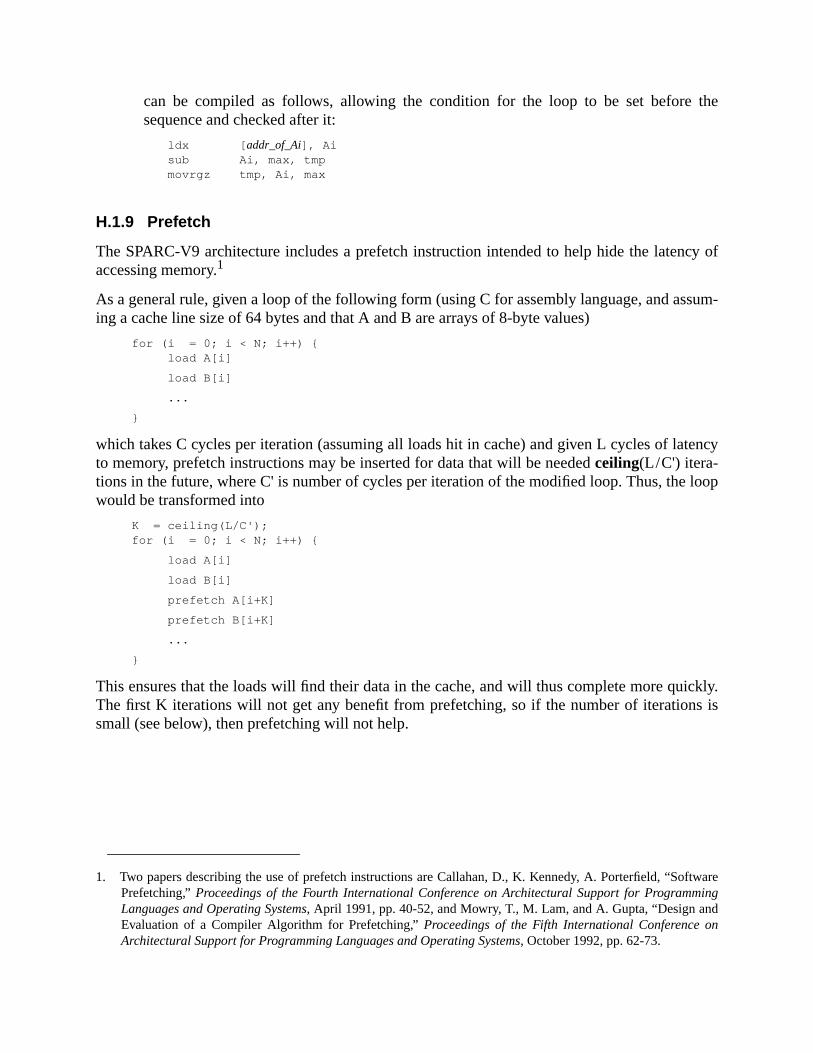
the
cy of
sum-
tency
loop
ickly.s is
ftwareingdn
can be compiled as follows, allowing the condition for the loop to be set beforesequence and checked after it:
ldx [ addr_of_Ai], Aisub Ai, max, tmpmovrgz tmp, Ai, max
H.1.9 Prefetch
The SPARC-V9 architecture includes a prefetch instruction intended to help hide the latenaccessing memory.1
As a general rule, given a loop of the following form (using C for assembly language, and asing a cache line size of 64 bytes and that A and B are arrays of 8-byte values)
for (i = 0; i < N; i++) {load A[i]
load B[i]
...
}
which takes C cycles per iteration (assuming all loads hit in cache) and given L cycles of lato memory, prefetch instructions may be inserted for data that will be neededceiling(L/C') itera-tions in the future, where C' is number of cycles per iteration of the modified loop. Thus, thewould be transformed into
K = ceiling(L/C');for (i = 0; i < N; i++) {
load A[i]
load B[i]
prefetch A[i+K]
prefetch B[i+K]
...
}
This ensures that the loads will find their data in the cache, and will thus complete more quThe first K iterations will not get any benefit from prefetching, so if the number of iterationsmall (see below), then prefetching will not help.
1. Two papers describing the use of prefetch instructions are Callahan, D., K. Kennedy, A. Porterfield, “SoPrefetching,”Proceedings of the Fourth International Conference on Architectural Support for ProgrammLanguages and Operating Systems, April 1991, pp. 40-52, and Mowry, T., M. Lam, and A. Gupta, “Design anEvaluation of a Compiler Algorithm for Prefetching,”Proceedings of the Fifth International Conference oArchitectural Support for Programming Languages and Operating Systems, October 1992, pp. 62-73.

ill instruc-
eed notny as
is nothingIn theg.
smarties to
Note that in cases of contiguous access (like this one), many of the prefetch instructions wfact be unnecessary and may slow the program down. To avoid this, note that the prefetch intion always obtains at least 64 (cache-line-aligned) bytes.
/* Round up access to next cache line. */K' = (ceiling(L/C') + 7) & ~7;
for (i = 0; i < N; i++) {
load A[i]
load B[i]
if ( ((int)(A+i) & 63) = = 0) {
prefetch A[i+K']
prefetch B[i+K']
}
...
}
or (unrolled eight times, assuming A and B are arrays of 8-byte values)
/* Be sure that we access the next cache line. */K'' = ceiling(L/C') + 7;
for (i = 0; i < N; i++) {
load A[i]
load B[i]
prefetch A[i+K'']
prefetch B[i+K'']
...
load A[i+1]
load B[i+2]
... (no prefetching)
...
load A[i+7]
load B[i+7]
...
}
In the first case, the prefetching is performed exactly when needed, and thus the distance nbe adjusted. However, the prefetching may not start on the first iteration, resulting in as maK' + 7 iterations without prefetching.
In the second case, the prefetching occurs somewhere within a cache line, and thus, itknown exactly how long it will be until the next cache line is needed. However, by prefetcseven further ahead, we ensure that the next cache line will be prefetched soon enough.worst case, as many as K'' (≤ K' + 7) iterations will execute without any benefit from prefetchin
Table 39 illustrates the cost tradeoffs between no prefetching, naive prefetching, andprefetching (the second choice) for a small loop (two cycles) with varying uncovered latenc
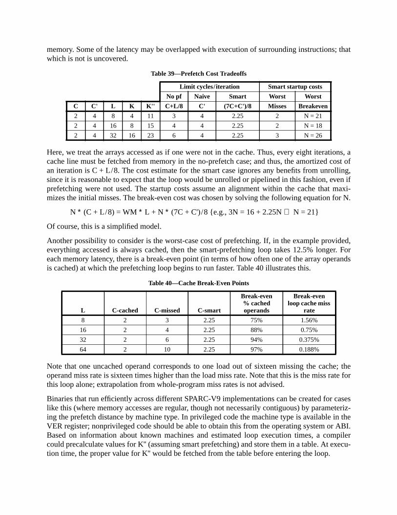
; that
tions, acost oflling,
ven ifmaxi-
for N.
ided,er. Forrands
he; theate for
caseseteriz-in theABI.
mpilerxecu-
memory. Some of the latency may be overlapped with execution of surrounding instructionswhich is not is uncovered.
Here, we treat the arrays accessed as if one were not in the cache. Thus, every eight iteracache line must be fetched from memory in the no-prefetch case; and thus, the amortizedan iteration is C + L/8. The cost estimate for the smart case ignores any benefits from unrosince it is reasonable to expect that the loop would be unrolled or pipelined in this fashion, eprefetching were not used. The startup costs assume an alignment within the cache thatmizes the initial misses. The break-even cost was chosen by solving the following equation
N ∗ (C + L/8) = WM ∗ L + N ∗ (7C + C')/8 {e.g., 3N = 16 + 2.25N⇒ N = 21}
Of course, this is a simplified model.
Another possibility to consider is the worst-case cost of prefetching. If, in the example proveverything accessed is always cached, then the smart-prefetching loop takes 12.5% longeach memory latency, there is a break-even point (in terms of how often one of the array opeis cached) at which the prefetching loop begins to run faster. Table 40 illustrates this.
Note that one uncached operand corresponds to one load out of sixteen missing the cacoperand miss rate is sixteen times higher than the load miss rate. Note that this is the miss rthis loop alone; extrapolation from whole-program miss rates is not advised.
Binaries that run efficiently across different SPARC-V9 implementations can be created forlike this (where memory accesses are regular, though not necessarily contiguous) by paraming the prefetch distance by machine type. In privileged code the machine type is availableVER register; nonprivileged code should be able to obtain this from the operating system orBased on information about known machines and estimated loop execution times, a cocould precalculate values for K'' (assuming smart prefetching) and store them in a table. At etion time, the proper value for K'' would be fetched from the table before entering the loop.
Table 39—Prefetch Cost Tradeoffs
Limit cycles/iteration Smart startup costs
No pf Naive Smart Worst Worst
C C' L K K'' C+L/8 C' (7C+C')/8 Misses Breakeven
2 4 8 4 11 3 4 2.25 2 N = 21
2 4 16 8 15 4 4 2.25 2 N = 18
2 4 32 16 23 6 4 2.25 3 N = 26
Table 40—Cache Break-Even Points
L C-cached C-missed C-smart
Break-even% cachedoperands
Break-evenloop cache miss
rate
8 2 3 2.25 75% 1.56%
16 2 4 2.25 88% 0.75%
32 2 6 2.25 94% 0.375%
64 2 10 2.25 97% 0.188%

block-int in
use ofuld beused.am-data),ecteded bus
ing ofrticular
visi-se arestruc-red to
load
ve the
read-ge “–
d by
than
s tords)
For regular but noncontiguous accesses, a prefetch would be issued for every load. If cacheing is used, the prefetching strategy must be adjusted accordingly, since there is no poprefetching data that is expected to be in the cache already.
The prefetch variant should be chosen based on what is known about the local and globalthe data prefetched. If the data is not being written locally, then variant 0 (several reads) shoused. If it is being written (and possibly also read), then variant 2 (several writes) should beIf, in addition, it is known that this is likely to be the last use of the data for some time (for exple, if the loop iteration count is one million and dependence analysis reveals no reuse ofthen it is appropriate to use either variant 1 (one read) or 3 (one write). If reuse of data is expto occur soon, then use of variants 1 or 3 is not appropriate, because of the risk of increasand memory traffic on a multiprocessor.
If the hardware does not implement all variants, it is expected to provide a sensible overloadthe unimplemented variants. Thus, correct use of a specific variant need not be tied to a paSPARC-V9 implementation or multi/uniprocessor configuration.
H.1.10 Nonfaulting Load
The SPARC-V9 architecture includes a way to specify load instructions that do not generateble faults, so that compilers can have more freedom in scheduling instructions. Note that thenot speculative loads, which may fault if their results are later used; these are normal load intions, but tagged to indicate to the kernel and/or hardware that a fault should not be delivethe code executing the instruction.
Five important rules govern the use of nonfaulting loads:
(1) Volatile memory references in the source language should not use nonfaultinginstructions.
(2) Code compiled for debugging should not use nonfaulting loads, because they remoability to detect common errors.
(3) If nonfaulting loads are used, page zero should be a page of zero values, mappedonly. Compilers that routinely use negative offsets to register pointers should map pa1” similarly, if the operating software permits it.
(4) Any use of nonfaulting loads in privileged code must be aware of how they are treatethe host SPARC-V9 implementation.
(5) Nonfaulting loads from unaligned addresses may be substantially more expensivenonfaulting loads from other addresses.
Nonfaulting loads can be used to solve three scheduling problems.
— On super-scalar machines, it is often desirable to obtain the right mix of instructionavoid conflicts for any given execution unit. A nonfaulting load can be moved (backwapast a basic block boundary to even out the instruction mix.

g loada reg-
th aad
e loadselined.
veddis-
— On pipelined machines, there may be latency between loads and uses. A nonfaultincan be moved past a block boundary to place more instructions between a load intoister and the next use of that register.
— Software pipelining improves the scheduling of loops, but if a loop iteration begins wiload instruction and contains an early exit, it may not be eligible for pipelining. If the lois replaced with a nonfaulting load, then the loop can be pipelined.
In the branch-laden code shown in example 2, nonfaulting loads could be used to separatfrom uses. The result also has a somewhat better mix of instructions and is somewhat pipThe basic blocks are separated.
In the loop shown in example 3, nonfaulting loads allow pipelining. This loop might be improfurther using unrolling, prefetching, and multiple FCCs, but that is beyond the scope of thiscussion.
Source Code:while ( x ! = 0 && x -> key ! = goal) x = x -> next;
With Normal Loads:entry:
brnz,a x,loop !
ldx [x],t1 ! (pre)load1 (key)
loop:
cmp t1,goal ! use1
bpe %xcc,out
nop ! no filling from loop.
ldx [x+8],x ! load2 (next)
brnz,a x,loop ! use2
ldx [x],t1 ! load1
out: ...
With Nonfaulting Loads:entry:
mov x,t2mov #ASI_PNF, %asildxa [t2]%asi,t1 ! (pre)load1 (nf-load for key)
loop:mov t2,x ! begin loop bodybrz,pn t2,outldxa [t2+8]%asi,t2 ! load2 (nf-load for next)
cmp t1,goal ! use1bpne %xcc,loopldxa [t2],%asi,t1 ! use2, load1 ! nf-load for x
out: ...
Example 2—Branch-Laden Code with Nonfaulting Loads
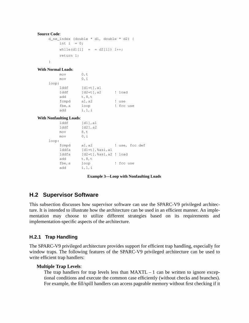
chitec-ple-and
y ford to
ep-hes).
g if it
H.2 Supervisor Software
This subsection discusses how supervisor software can use the SPARC-V9 privileged arture. It is intended to illustrate how the architecture can be used in an efficient manner. An immentation may choose to utilize different strategies based on its requirementsimplementation-specific aspects of the architecture.
H.2.1 Trap Handling
The SPARC-V9 privileged architecture provides support for efficient trap handling, especiallwindow traps. The following features of the SPARC-V9 privileged architecture can be usewrite efficient trap handlers:
Multiple Trap Levels :The trap handlers for trap levels less than MAXTL – 1 can be written to ignore exctional conditions and execute the common case efficiently (without checks and brancFor example, the fill/spill handlers can access pageable memory without first checkin
Example 3—Loop with Nonfaulting Loads
Source Code:d_ne_index (double * d1, double * d2) {
int i = 0;
while(d1[i] = = d2[i]) i++;
return i;
}
With Normal Loads:mov 0,tmov 0,i
loop:lddf [d1+t],a1lddf [d2+t],a2 ! loadadd t,8,tfcmpd a1,a2 ! usefbe,a loop ! fcc useadd i,1,i
With Nonfaulting Loads:lddf [d1],a1lddf [d2],a2mov 8,tmov 0,i
loop:fcmpd a1,a2 ! use, fcc deflddfa [d1+t],%asi,a1lddfa [d2+t],%asi,a2 ! loadadd t,8,tfbe,a loop ! fcc useadd i,1,i

ndled
thatpportareas
it reg-, thestruc-
stored)ade
gister.
f thet a
sor
global.
ir ofhus
catedthecode
cli-nted effi-
cross-
is resident. If the memory is not resident, the access will cause a trap that will be haat the next trap level.
Vectoring of Fill/Spill Traps :Supervisor software can set up the vectoring of fill/spill traps prior to executing codeuses register windows and may cause spill/fill traps. This feature can be used to suSPARC-V8 and SPARC-V7 binaries. These binaries create stack frames with savefor 32-bit registers. SPARC-V9 binaries create stack frames with save areas for 64-bisters. By setting up the spill/fill trap vector based on the type of binary being executedtrap handlers can avoid checking and branching to use the appropriate load/store intions.
Saved Trap State:Trap handlers need not save (restore) processor state that is automatically saved (reon a trap (return from trap). For example, the fill/spill trap handlers can loASI_AS_IF_USER_PRIMARY{_LITTLE} into the ASI register in order to access thuser’s address space without the overhead of having to save and restore the ASI re
SAVED and RESTORED Instructions:The SAVED (RESTORED) instruction provides an efficient way to update the state oregister windows after successfully spilling (filling) a register window. They implemendefault policy of spilling (filling) one register window at a time. If desired, the supervisoftware can implement a different policy by directly updating the state registers.
Alternate Globals:The alternate global registers can be used to avoid saving and restoring the normalregisters. They can be used like the local registers of the trap window in SPARC-V8
Large Trap Vectors for Spill/Fill :The definition of the spill and fill trap vectors with reserved space between each pavectors allows spill and fill trap handlers to be up to thirty-two instructions long, tavoiding a branch in the handler.
H.2.2 Example Code for Spill Handler
The code in example 4 shows a spill handler for a SPARC-V9 user binary. The handler is loat the vector for trap typespill_0_normal (08016). It is assumed that supervisor software has setWSTATE register to 0 before executing the user binary. The handler is invoked when userexecutes a SAVE instruction that results in a window overflow.
H.2.3 Client-Server Model
SPARC-V9 provides mechanisms to support client-server computing efficiently. A call from aent to a server (where the client and server have separate address spaces) can be implemeciently using a software trap that switches the address space. This is often referred to as across-domain call. A system call in most operating systems can be viewed as a special case of adomain call. The following features are useful in implementing a cross-domain call:

ng thethercan setRE-et to
the sim-neral
accessovidedntially
s ontedr trapp han-
Splitting the Register Windows
The register windows can be shared efficiently between multiple address spaces by usiOTHERWIN register and providing additional trap handlers to handle spill/fill traps for the o(not the current) address spaces. On a cross-domain call (a software trap), the supervisorthe OTHERWIN register to the number of register windows used by the client (equal to CANSTORE) and CANRESTORE to zero. At the same time the WSTATE bit vectors can be svector the spill/fill traps appropriately for each address space.
The sequence in example 5 shows a cross-domain call and return. The example assumesple case, where only a single client-server pair can occupy the register windows. More geschemes can be developed along the same lines.
ASI_SECONDARY{_LITTLE}
Supervisor software can use these unrestricted ASIs to support cross-address-spacebetween clients and nonprivileged servers. For example, some services that are currently pras part of a large monolithic supervisor can be separated out as nonprivileged servers (poteoccupying a separate address space). This is often referred to as themicrokernel approach.
H.2.4 User Trap Handlers
Supervisor software can provide efficient support for user (nonprivileged) trap handlerSPARC-V9. The RETURN instruction allows nonprivileged code to retry an instruction pointo by the previous stack frame. This provides the semantics required for returning from a usehandler without any change in processor state. Supervisor software can invoke the user tra
T_NORMAL_SPILL_0:!Set ASI to access user addr spacewr #ASI_AIUP, %asistxa %l0, [%sp+(8* 0)]%asi !Store window in memory stackstxa %l1, [%sp+(8* 1)]%asistxa %l2, [%sp+(8* 2)]%asistxa %l3, [%sp+(8* 3)]%asistxa %l4, [%sp+(8* 4)]%asistxa %l5, [%sp+(8* 5)]%asistxa %l6, [%sp+(8* 6)]%asistxa %l7, [%sp+(8* 7)]%asistxa %i0, [%sp+(8* 8)]%asistxa %i1, [%sp+(8* 9)]%asistxa %i2, [%sp+(8*10)]%asistxa %i3, [%sp+(8*11)]%asistxa %i4, [%sp+(8*12)]%asistxa %i5, [%sp+(8*13)]%asistxa %i6, [%sp+(8*14)]%asistxa %i7, [%sp+(8*15)]%asisaved ! Update stateretry ! Retry trapped instruction
! Restores old %asi
Example 4—Spill Handler

eces-. The
dler by first creating a new register window (and stack frame) on its behalf and passing the nsary arguments (including the PC and nPC for the trapped instruction) in the local registerscode in example 6 shows how a user trap handler may be invoked and how it returns:
(This Annex is not a part of SPARC-V9/R1.4.5,<Italic>The SPARC Architecture Manual;
it is included for information only.)
cross_domain_call:save ! create a new register window for the server.. ! Switch to the execution environment for the server;.. ! Save trap state as necessary.
! Set CWP for caller in TSTATErdpr %tstate, %g1rdpr %cwp, %g2bclr TSTATE_CWP, %g1wrpr %g1, %g2, %tstaterdpr %canrestore, %g1wrpr %g0, 0, %canrestorewrpr %g0, %g1, %otherwinrdpr %wstate, %g1sll %g1, 3, %g1 ! Move WSTATE_NORMAL (client’s
! vector)to WSTATE_OTHERor %g1, WSTATE_SERVER, %g1 ! Set WSTATE_NORMAL to the
! vector for the serverwrpr %g0, %g1, %wstate.. ! Load trap state for serverdone ! Execute server code
cross_domain_return:rdpr %otherwin, %g1wrpr %g0, %g1, %canrestorewrpr %g0, 0, %otherwinrdpr %wstate, %g1srl %g1, 3, %g1wrpr %g0, %g1, %wstate ! Reset WSTATE_NORMAL to
! client’s vector.. ! Restore saved trap state as necessary; this includes
! the return PC for the caller.restore ! Go back to the caller’s register window.
! Set CWP for caller in TSTATErdpr %tstate, %g1rdpr %cwp, %g2bclr TSTATE_CWP, %g1wrpr %g1, %g2, %tstate
done ! return to the caller
Example 5—Cross-Domain Call and Return

cture.y state
C-V9ction
I Extending the SPARC-V9 ArchitectureThis appendix describes how extensions can be effectively added to the SPARC-V9 architeIt describes how new instructions can be added through the use of read and write ancillarregister (ASR) and implementation-dependent (IMPDEP1/IMPDEP2) instructions.
I.1 Addition of SPARC-V9 Extensions
There are two approved methods of adding extensions to an implementation of the SPARarchitecture. An implementor who wishes to define and implement a new SPARC-V9 instrushould, if possible, use one of the following methods.
T_EXAMPLE_TRAP: ! Supervisor trap handler for T_EXAMPLE_TRAP trapsave ! Create a window for the user trap handler
!Set CWP for new window in TSTATErdpr %tstate, %l6rdpr %cwp, %l5bclr TSTATE_CWP, %l6wrpr %l6, %l5, %tstate
rdpr %tpc,%l6 !Put PC for trapped instruction in local registerrdpr %tnpc,%l7 !Put nPC for trapped instruction in local register.. !Get the address of the user trap handler in %l5;
! for example, from a supervisor data structure.
wrpr %l5, %tnpc ! Put PC for user trap handler in %tnpc.done ! Execute user trap handler.
USER_EXAMPLE_TRAP: !User trap handler for T_EXAMPLE_TRAP trap
.. !Execute trap handler logic. Local registers! can be used as scratch.
jmpl %l6 !Return to retry the trapped instruction.return %l7
Example 6—User Trap Handler
This appendix is informative only.
It is not part of the SPARC-V9 specification.
Programs that make use of SPARC-V9 architectural extensionsmay not be portable and likely will not conform to any current orfuture SPARC-V9 binary standards.
— WARNING —
tion-SR)that
sosignedad the
Theple-will be
codesrvedcom-Hard-e, but
futurethis in
plica-erved
fewmust
atible
eitherrs. The-V8, as
P1,lated,
ationale canrwardinat-
I.1.1 Read/Write Ancillary State Registers (ASRs)
The first method of adding instructions to SPARC-V9 is through the use of the implementadependent Write Ancillary State Register (WRASR) and Read Ancillary State Register (RDAinstructions operating on ASRs 16..31. Through a read/write instruction pair, any instructionrequires anrs1, reg_or_imm, andrd field can be implemented. A WRASR instruction can alperform an arbitrary operation on two register sources, or on one register source and aimmediate value, and place the result in an ASR. A subsequent RDASR instruction can reresult ASR and place its value in an integer destination register.
I.1.2 Implementation-Dependent and Reserved Opcodes
The meaning of “reserved” for SPARC-V9 opcodes differs from its meaning in SPARC-V8.SPARC-V9 definition of “reserved” allows implementations to use reserved opcodes for immentation-specific purposes. While a hardware implementation that uses reserved opcodesSPARC-V9-compliant, SPARC-V9 ABI-compliant programs cannot use these reserved opand remain compliant. A SPARC-V9 platform that implements instructions using reseopcodes must provide software libraries that provide the interface between SPARC-V9 ABI-pliant programs and these instructions. Graphics libraries provide a good example of this.ware platforms have many diverse implementations of graphics acceleration hardwargraphics application programs are insulated from this diversity through libraries.
There is no guarantee that a reserved opcode will not be used for additional instructions in aversion of the SPARC architecture. Implementors who use reserved opcodes should keepmind.
In some cases forward compatibility may not be an issue; for example, in an embedded aption, binary compatibility may not be an issue. These implementations can use any resopcodes for extensions.
Even when forward compatibility is an issue, future SPARC revisions are likely to containchanges to opcode assignments, given that backward compatibility with previous versionsbe maintained. It is recommended that implementations wishing to remain forward-compuse the new IMPDEP1 and IMPDEP2 reserved opcodes withop3[5:0] = 11 01102 and 11 01112.
Compatibility Note:IMPDEP1 and IMPDEP2 replace the SPARC-V8 CPop1 and CPop2 opcodes. SPARC-V9 includes nthe SPARC-V8 coprocessor opcodes nor any other SPARC-V8 architectural support for coprocessocoprocessor opcodes were eliminated because they have not been used in SPARC-V7 and SPARCwitnessed by the lack of coprocessor implementations.
It is further recommended that SPARC International be notified of any use of IMPDEIMPDEP2, or other reserved opcodes. When and if future revisions to SPARC are contempand if any SPARC-V9 implementations have made use of reserved opcodes, SPARC Internwill make every effort not to use those opcodes. By going through SPARC International, therbe feedback and coordination in the choice of opcodes that maximizes the probability of focompatibility. Given the historically small number of implementation-specific changes, coording through SPARC International should be sufficient to ensure future compatibility.
itiveeci-ec-how
ngereakerf mem-del.odel
h the
. Theuired
P, ande cop-and-n andn thee, and
ansitionEM-BARjacent
(This Annex is not a part of SPARC-V9/R1.4.5,<Italic>The SPARC Architecture Manual;
it is included for information only.)
J Programming With the Memory ModelsThis appendix describes how to program with the SPARC-V9 memory models. An intudescription of the models is provided in Chapter 8, “Memory Models.” A complete formal spfication appears in Appendix D, “Formal Specification of the Memory Models.” In this substion, general programming guidelines are given first, followed by specific examples showinglow-level synchronization can be implemented in TSO, PSO, and RMO.
Note that code written for a weaker memory model will execute correctly in any of the stromemory models. Furthermore, the only possible difference between code written for a wmemory model and the corresponding code for a stronger memory model is the presence oory ordering instructions (MEMBARs) that are not needed for the stronger memory moHence, transforming code from/to a stronger memory model to/from a weaker memory mmeans adding/removing certain memory ordering instructions.1 The required memory orderingdirectives are monotonically ordered with respect to the strength of the memory model, witweakest memory model requiring the strongest memory ordering instructions.
The code examples given below are written to run correctly using the RMO memory modelcomments on the MEMBAR instructions indicate which ordering constraints (if any) are reqfor the PSO and TSO memory models.
J.1 Memory Operations
Programs access memory via five types of operations, namely, load, store, LDSTUB, SWAcompare-and-swap. Load copies a value from memory or an I/O location to a register. Stories a value from a register into memory or an I/O location. LDSTUB, SWAP, and compare-swap are atomic load-store instructions that store a value into memory or an I/O locatioreturn the old value in a register. The value written by the atomic instructions depends oinstruction. LDSTUB stores all ones in the accessed byte, SWAP stores the supplied valu
1. MEMBAR instructions specify seven independent ordering constraints; thus, there are cases where the trto a stronger memory model allows the use of a less restrictive MEMBAR instruction, but still requires a MBAR instruction. To demonstrate this property, the code examples given in this subsection use multiple MEMinstructions if some of the ordering constraints are needed in some but not all memory models. Multiple, adMEMBAR instructions can always be replaced with a single MEMBAR instruction byORing the arguments.
This appendix is informative only.
It is not part of the SPARC-V9 specification.

pplied
EM-resemory.
thistions
tores
ome
moryTSOcy isdel is
morynitiate
egreeper-
r mul-
y theprop-oper-
pletely
d thatroces-
compare-and-swap stores the supplied value only if the old value equals the second suvalue.
Memory order and consistency are controlled by MEMBAR instructions. For example, a MBAR #StoreStore (equivalent to a STBAR in SPARC-V8) ensures that all previous stohave been performed before subsequent stores and atomic load-stores are executed by mThis particular memory order is guaranteed implicitly in TSO, but PSO and RMO requireinstruction if the correctness of a program depends on the order in which two store instruccan be observed by another processor.1
FLUSH is not a memory operation, but it is relevant here in the context of synchronizing swith instruction execution. When a processor modifies an instruction at addressA, it does a storeto A followed by a FLUSHA. The FLUSH ensures that the change made by the store will becvisible to the instruction fetch units of all processors in the system.
J.2 Memory Model Selection
Given that all SPARC-V9 systems are required to support TSO, programs written for any memodel will be able to run on any SPARC-V9 system. However, a system running with themodel generally will offer lower performance than PSO or RMO, because less concurrenexposed to the CPU and the memory system. The motivation for weakening the memory moto allow the CPU to issue multiple, concurrent memory references in order to hide melatency and increase access bandwidth. For example, PSO and RMO allow the CPU to inew store operations before an outstanding store has completed.
Using a weaker memory model for an MP (multiprocessor) application that exhibits a high dof read-write memory sharing with fine granularity and a high frequency of synchronization oations may result in frequent MEMBAR instructions.
In general, it is expected that the weaker memory models offer a performance advantage fotiprocessor SPARC-V9 implementations.
J.3 Processors and Processes
In the SPARC-V9 memory models, the term “processor” may be replaced systematically bterm “process” or “thread,” as long as the code for switching processes or threads is writtenerly. The correct process-switch sequence is given in J.8, “Process Switch Sequence.” If anating system implements this process-switch sequence, application programmers may comignore the difference between a process/thread and a processor.
1. Memory order is of concern only to programs containing multiple threads that share writable memory anmay run on multiple processors, and to those programs which reference I/O locations. Note that from the psor’s point of view, I/O devices behave like other processors.
tion islan-tomic
erally
the
servesingle
upports of a, andmples
istent
onizesty:
y inaking
ughes to
r.
-writethem-im-Note lock.
rtable
and
ory
J.4 Higher-Level Programming Languages and Memory Models
The SPARC-V9 memory models are defined at the machine instruction level. Special attenrequired to write the critical parts of MP/MT (multi-threaded) applications in a higher-levelguage. Current higher-level languages do not support memory ordering instructions and aoperations. As a result, MP/MT applications that are written in a higher-level language genwill rely on a library of MP/MT support functions, for example, theparmacs library fromArgonne National Laboratory.1 The details of constructing and using such libraries are beyondscope of this document.
Compiler optimizations such as code motion and instruction scheduling generally do not prethe order in which memory is accessed but they do preserve the data dependencies of athread. Compilers do not, in general, deal with the additional dependency requirements to ssharing read-write data among multiple concurrent threads. Hence, the memory semanticSPARC-V9 system in general are not preserved by optimizing compilers. For this reasonbecause memory ordering directives are not available from higher-level languages, the exapresented in this subsection use assembly language.
Future compilers may have the ability to present the programmer with a sequentially consmemory model despite the underlying hardware’s providing a weaker memory model.2
J.5 Portability And Recommended Programming Style
Whether a program is portable across various memory models depends on how it synchraccess to shared read-write data. Two aspects of a program’s style are relevant to portabili
— Good semanticsrefers to whether the synchronization primitives chosen and the wawhich they are used are such that changing the memory model does not involve many changes to the code that uses the primitives.
— Good structure refers to whether the code for synchronization is encapsulated throthe use of primitives such that when the memory model is changed, required changthe code are confined to the primitives.
Good semantics are a prerequisite for portability, while good structure makes porting easie
Programs that use single-writer/multiple-reader locks to protect all access to shared readdata are portable across all memory models. The code that implements the lock primitivesselves is portable across all models only if it is written to run correctly on RMO. If the lock pritives are collected into a library, then, at worst, only the library routines must be changed.that mutual exclusion (mutex) locks are a degenerate type of single-writer/multiple-readers
Programs that use write locks to protect write accesses but read without locking are poacross all memory models only if writes to shared data are separated by MEMBAR#Store-
1. Lusk, E. L., R.A. Overbeek, “Use of Monitors in Fortran: A Tutorial on the Barrier, Self-scheduling Do-Loop,Askfor Monitors,” TR# ANL-84-51, Argonne National Laboratory, June 1987.
2. See Gharachorloo, K., S.V. Adve, A. Gupta, J.L. Hennessy, and M.D. Hill, “Programming for Different MemConsistency Models,” Journal of Parallel and Distributed Systems, 15:4, August 1992.

rongtheherou-
cks,isely,most
d, andlsorittentrongshown
writer/niza-suchthe
to a
RC-V9-tial con-r tech-ly (and
Store instructions, and if reading the lock is followed by a MEMBAR#LoadLoad instruc-tion. If the MEMBAR instructions are omitted, the code is portable only across TSO and StConsistency,1 but generally it will not work with PSO and RMO. The code that implementslock primitives is portable across all models only if it is written to run correctly on RMO. If tlock routines are collected into a library, the only possible changes not confined to the librarytines are the MEMBAR instructions.
Programs that do synchronization without using single-writer/multiple-reader locks, write loor their equivalent are, in general, not portable across different memory models. More precthe memory models are ordered from RMO (which is the weakest, least constrained, andconcurrent), PSO, TSO, to sequentially consistent (which is the strongest, most constraineleast concurrent). A program written to run correctly for any particular memory model will arun correctly in any of the stronger memory models, but not vice versa. Thus, programs wfor RMO are the most portable, those written for TSO are less so, and those written for sconsistency are the least portable. This general relationship between the memory models isgraphically in figure 49.
Figure 49—Portability Relations among Memory Models
The style recommendations may be summarized as follows: Programs should use single-multiple-reader locks, or their equivalent, when possible. Other lower-level forms of synchrotion (such as Dekker’s algorithm for locking) should be avoided when possible. When use oflow-level primitives is unavoidable, it is recommended that the code be written to work onRMO model to ensure portability. Additionally, lock primitives should be collected together inlibrary and written for RMO to ensure portability.
1. Programs that assume a sequentially consistent memory are not guaranteed to run correctly on any SPAcompliant system, since TSO is the strongest memory model required to be supported. However, sequensistency is the most natural and intuitive programming model. This motivates the development of compileniques that allow programs written for sequential consistency to be translated into code that runs correctefficiently) on systems with weaker memory models.
Strong Consistency
TSO
PSO
RMO

that
inr theat the
d loca-re
nzero. Theer ofver-
its by
buffer,ducerocess
Appendix D, “Formal Specification of the Memory Models,” describes a tool and methodallows short code sequences to be formally verified for correctness.
J.6 Spin Locks
A spin lock is a lock for which the “lock held” condition is handled by busy waiting. The codeexample 7 shows how spin locks can be implemented using LDSTUB. A nonzero value folock represents the locked condition, while a zero value means that the lock is free. Note thcode busy waits by doing loads to avoid generating expensive stores to a potentially sharetion. TheMEMBAR #StoreStore in UnLockWithLDSTUB ensures that pending stores acompleted before the store that frees the lock.
The code in example 8 shows how spin locks can be implemented using CASA. Again, a novalue for the lock represents the locked condition, while a zero value means the lock is freenonzero lock value (ID) is supplied by the caller and may be used to identify the current ownthe lock. This value is available while spinning and could be used to maintain a time-out or toify that the thread holding the lock is still running. As in the previous case, the code busy-wadoing loads, not stores.
J.7 Producer-Consumer Relationship
In a producer-consumer relationship,the producer process generates data and puts it into awhile the consumer process takes data from the buffer and uses it. If the buffer is full, the proprocess stalls when trying to put data into the buffer. If the buffer is empty, the consumer prstalls when trying to remove data.
LockWithLDSTUB ( lock )
retry:ldstub [ lock ],%l0tst %l0be outnop
loop:ldub [ lock ],%l0tst %l0bne loopnopba,a retry
out:membar #LoadLoad | #LoadStore
UnLockWithLDSTUB ( lock )membar #StoreStore !RMO and PSO onlymembar #LoadStore !RMO onlystub %g0,[ lock ]
Example 7—Lock and Unlock Using LDSTUB

cer and
Figure 50 shows the buffer data structure and register usage. Example 9 shows the produconsumer code. The code assumes the existence of two procedures,IncrHead andIncrTail ,LockWithCAS ( lock , ID )retry:
mov [ID],%l0cas [ lock ],%g0,%l0tst %l0be outnop
loop:ld [ lock ],%l0tst %l0bne loopnopba,a retry
out:membar #LoadLoad | #LoadStore !See example 7
UnLockWithCAS ( lock )membar #StoreStore !RMO and PSO onlymembar #LoadStore !RMO onlyst %g0,[ lock ]
Example 8—Lock and Unlock Using CAS
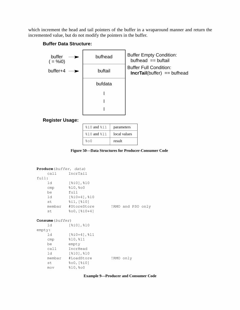
rn the
which increment the head and tail pointers of the buffer in a wraparound manner and retuincremented value, but do not modify the pointers in the buffer.bufhead
buftail
bufdata
l
l
l
buffer Buffer Empty Condition:bufhead == buftail
Buffer Full Condition:IncrTail (buffer) == bufheadbuffer+4
( = %i0)
Buffer Data Structure:
Register Usage:%i0 and%i1
%o0
%l0 and%l1
parameters
local values
result
Figure 50—Data Structures for Producer-Consumer Code
Produce ( buffer , data )call IncrTail
full:ld [%i0],%l0cmp %l0,%o0be fullld [%i0+4],%l0st %i1,[%l0]membar #StoreStore !RMO and PSO onlyst %o0,[%i0+4]
Consume( buffer )ld [%i0],%l0
empty:ld [%i0+4],%l1cmp %l0,%l1be emptycall IncrHeadld [%l0],%l0membar #LoadStore !RMO onlyst %o0,[%i0]mov %l0,%o0
Example 9—Producer and Consumer Code

ure that
on alin-
variablees)
rocessor
hatprocess
quenceble by
singmay
em init(and
opriateuiv-
J.8 Process Switch Sequence
This subsection provides code that must be used during process or thread switching to ensthe memory model seen by a process or thread is the one seen by a processor. TheHeadSe-quence must be inserted at the beginning of a process or thread when it starts executingprocessor. TheTailSequence must be inserted at the end of a process or thread when it requishes a processor.
Example 10 shows the head and tail sequences. The two sequences refer to a per-processtailDone. The value 0 fortailDonemeans that the process is running, while the value –1 (all onmeans that the process has completed its tail sequence and may be migrated to another pif the process is runnable. When a new process is created,tailDone is initialized to –1.
The MEMBAR in HeadSequence is required to be able to provide a switching sequence tensures that the state observed by a process in its source processor will also be seen by thein its destination processor. Since FLUSHes and stores are totally ordered, the head seneed not do anything special to ensure that FLUSHes performed prior to the switch are visithe new processor.
Programming Note:A conservative implementation may simply use a MEMBAR with all barriers set.
J.9 Dekker’s Algorithm
Dekker’s algorithm is the classical sequence for synchronizing entry into a critical section uloads and stores only. The reason for showing this example here is to illustrate how oneensure that a store followed by a load in issuing order will be executed by the memory systthat order. Dekker’s algorithm isnot a valid synchronization primitive for SPARC-V9, becauserequires a sequentially consistent (SC) memory model in order to work. Dekker’s algorithmsimilar synchronization sequences) can be coded on RMO, PSO, and TSO by adding apprMEMBAR instructions. This example also illustrates how future compilers can provide the eqalent of sequential consistency on systems with weaker memory models.
HeadSequence ( tailDone )nrdy:
ld [ tailDone ],%l0cmp %l0,-1bne nrdyst %g0, [ tailDone ]membar #StoreLoad
TailSequence ( tailDone )mov -1,%l0membar #StoreStore !RMO and PSO onlymembar #LoadStore !RMO only (combine with above)st %l0,[ tailDone ]
Example 10—Process or Thread Switch Sequence

anyn,
dead-with-
n eachas no
ategy, such
at theking.
Example 11 shows the entry and exit sequences for Dekker’s algorithm. The locationsA andB areused for synchronization;A = 0 means that process P1 is outside its critical section, whileother value means that P1 is inside it; similarly,B = 0 means that P2 is outside its critical sectioand any other value means that P2 is inside it.
Dekker’s algorithm guarantees mutual exclusion, but it does not guarantee freedom fromlock. In this case, it is possible that both processors end up trying to enter the critical regionout success. The code above tries to address this problem by briefly releasing the lock iretry loop. However, both stores are likely to be combined in a store buffer, so the release hchance of success. A more realistic implementation would use a probabilistic back-off strthat increases the released period exponentially while waiting. If any randomization is usedan algorithm will avoid deadlock with arbitrarily high probability.
J.10 Code Patching
The code patching example illustrates how to modify code that is potentially being executedtime of modification. Two common uses of code patching are in debuggers and dynamic lin
P1Entry ( )mov -1,%l0
busy:st %l0,[A]membar #StoreLoadld [ B],%l1tst %l1bne,a busyst %g0,[ A]
P1Exit ( )membar #StoreStore !RMO and PSO onlymembar #LoadStore !RMO onlyst %g0,[ A]
P2Entry ( )mov -1,%l0
busy:st %l0,[B]membar #StoreLoadld [ A],%l1tst %l1bne,a busyst %g0,[ B]
P2Exit ( )membar #StoreStore !RMO and PSO onlymembar #LoadStore !RMO onlyst %g0,[ B]
Example 11—Dekker’s Algorithm
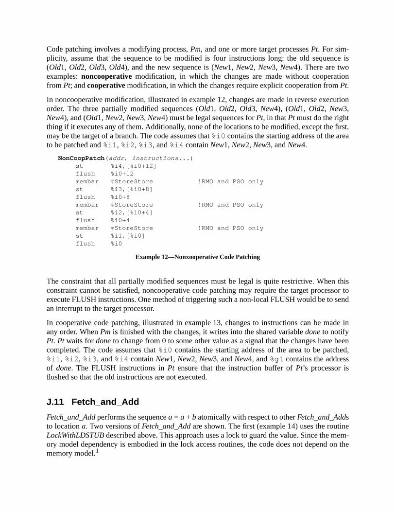
nce is
ion
cution
first,ea
n thisssor tosend
ade in
beened,
nemem-on the
Code patching involves a modifying process,Pm, and one or more target processesPt. For sim-plicity, assume that the sequence to be modified is four instructions long: the old seque(Old1, Old2, Old3, Old4), and the new sequence is (New1, New2, New3, New4). There are twoexamples:noncooperative modification, in which the changes are made without cooperatfrom Pt; andcooperativemodification, in which the changes require explicit cooperation fromPt.
In noncooperative modification, illustrated in example 12, changes are made in reverse exeorder. The three partially modified sequences (Old1, Old2, Old3, New4), (Old1, Old2, New3,New4), and (Old1, New2, New3, New4) must be legal sequences forPt, in thatPt must do the rightthing if it executes any of them. Additionally, none of the locations to be modified, except themay be the target of a branch. The code assumes that%i0 contains the starting address of the arto be patched and%i1 , %i2 , %i3 , and%i4 containNew1, New2, New3, andNew4.
The constraint that all partially modified sequences must be legal is quite restrictive. Wheconstraint cannot be satisfied, noncooperative code patching may require the target proceexecute FLUSH instructions. One method of triggering such a non-local FLUSH would be toan interrupt to the target processor.
In cooperative code patching, illustrated in example 13, changes to instructions can be many order. WhenPm is finished with the changes, it writes into the shared variabledoneto notifyPt. Pt waits fordoneto change from 0 to some other value as a signal that the changes havecompleted. The code assumes that%i0 contains the starting address of the area to be patch%i1 , %i2 , %i3 , and%i4 containNew1, New2, New3, andNew4, and%g1contains the addressof done. The FLUSH instructions inPt ensure that the instruction buffer ofPt’s processor isflushed so that the old instructions are not executed.
J.11 Fetch_and_Add
Fetch_and_Addperforms the sequencea = a + b atomically with respect to otherFetch_and_Addsto locationa. Two versions ofFetch_and_Addare shown. The first (example 14) uses the routiLockWithLDSTUBdescribed above. This approach uses a lock to guard the value. Since theory model dependency is embodied in the lock access routines, the code does not dependmemory model.1
NonCoopPatch ( addr , instructions ...)st %i4,[%i0+12]flush %i0+12membar #StoreStore !RMO and PSO onlyst %i3,[%i0+8]flush %i0+8membar #StoreStore !RMO and PSO onlyst %i2,[%i0+4]flush %i0+4membar #StoreStore !RMO and PSO onlyst %i1,[%i0]flush %i0
Example 12—Nonxooperative Code Patching

anst and
e
Fetch_and_Addoriginally was invented to avoid lock contention and to provide an efficient meto maintain queues and buffers without cumbersome locks. Hence, using a lock is inefficiencontrary to the intentions of theFetch_and_Add. The CAS synthetic instruction allows a morefficient version, as shown in example 15.
1. Inlining of the lock-access functions with subsequent optimization may break this code.
CoopPatch ( addr , instructions ...) !%i0 = addr , %i1..%i4 = instruction sst %i1,[%i0]st %i2,[%i0+4]st %i3,[%i0+8]st %i4,[%i0+12]mov -1,%l0membar #StoreStore !RMO and PSO onlyst %l0,[%g1]
TargetCode ( )wait:
ld [%g1],%l0cmp %l0,0be waitflush Aflush A+4flush A+8flush A+12
A:Old1Old2Old3Old4
Example 13—Cooperative Code Patching
/*Fetch and Add using LDSTUB*/int Fetch_And_Add(Index, Increment, Lock)
int *Index;int Increment;int *Lock;{
int old_value;LockWithLDSTUB(Lock);old_value = *Index;*Index = old_value + Increment;UnlockWithLDSTUB(Lock);return(old_value);
}
Example 14—Fetch and Add Using LDSTUB

ene thete,
lock
lock
rationmeans
ry ver-, pass-
by the
arrier.
on theultiple
J.12 Barrier Synchronization
Barrier synchronization ensures that each ofN processes is blocked until all of them reach a givstate. The point in the flow of control at which this state is reached is called the barrier; hencname. The code uses the variableCountinitialized toN. As each process reaches its desired stait decrementsCount and waits forCount to reach zero before proceeding further.
Similar to the fetch and add operation, barrier synchronization is easily implemented using ato guard the counter variable, as shown in example 16.
The CAS implementation of barrier synchronization, shown in example 17, avoids the extraaccess.
A practical barrier synchronization must be reusable because it is typically used once per itein applications that require many iterations. Barriers that are based on counters must haveto reset the counter. One solution to this problem is to alternate between two complementasions of the barrier: one that counts down to 0 and the other that counts up to N. In this caseing one barrier also initializes the counter for the next barrier.
Passing a barrier can also signal that the results of one iteration are ready for processingnext iteration. In this case, RMO and PSO require aMEMBAR #StoreStore instruction prior tothe barrier code to ensure that all local results become globally visible prior to passing the b
Barrier synchronization among a large number of processors will lead to access contentioncounter variable, which may degrade performance. This problem can be solved by using m
FetchAndAddCAS( address , increment ) !%i0 = address , %i1 = incrementretry:
ld [%i0],%l0add %l0,%i1,%l1cas [%i0],%l0,%l1cmp %l0,%l1bne retrymov %l1,%o0 !return old value
Example 15—Fetch and Add Using CAS
/*Barrier Synchronization using LDSTUB*/Barrier(Count,Lock)int *Count;int *Lock;{
LockWithLdstUB(Lock);*Count = *Count - 1;UnlockWithLdstUB(Lock);while(*Count > 0) { ; /*busy-wait*/ }
}
Example 16—Barrier Synchronization Using LDSTUB
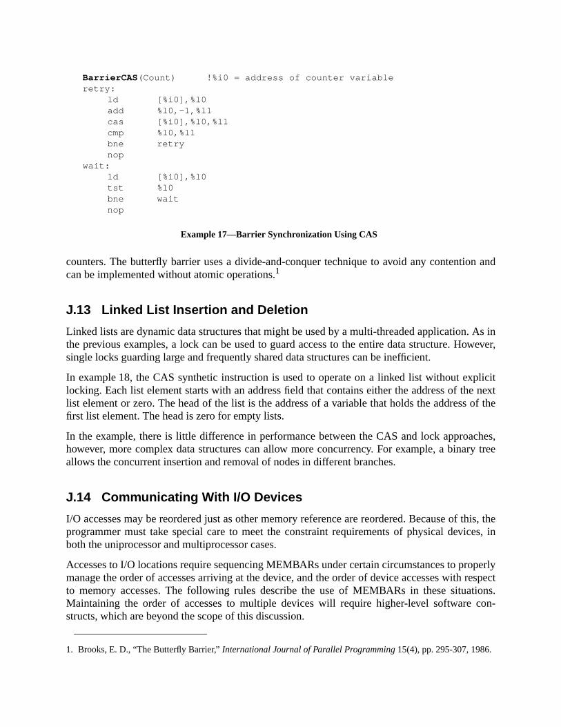
n and
As inowever,
plicite nextof the
ches,ry tree
this, theces, in
operlyrespect
tions.con-
counters. The butterfly barrier uses a divide-and-conquer technique to avoid any contentiocan be implemented without atomic operations.1
J.13 Linked List Insertion and Deletion
Linked lists are dynamic data structures that might be used by a multi-threaded application.the previous examples, a lock can be used to guard access to the entire data structure. Hsingle locks guarding large and frequently shared data structures can be inefficient.
In example 18, the CAS synthetic instruction is used to operate on a linked list without exlocking. Each list element starts with an address field that contains either the address of thlist element or zero. The head of the list is the address of a variable that holds the addressfirst list element. The head is zero for empty lists.
In the example, there is little difference in performance between the CAS and lock approahowever, more complex data structures can allow more concurrency. For example, a binaallows the concurrent insertion and removal of nodes in different branches.
J.14 Communicating With I/O Devices
I/O accesses may be reordered just as other memory reference are reordered. Because ofprogrammer must take special care to meet the constraint requirements of physical deviboth the uniprocessor and multiprocessor cases.
Accesses to I/O locations require sequencing MEMBARs under certain circumstances to prmanage the order of accesses arriving at the device, and the order of device accesses withto memory accesses. The following rules describe the use of MEMBARs in these situaMaintaining the order of accesses to multiple devices will require higher-level softwarestructs, which are beyond the scope of this discussion.
1. Brooks, E. D., “The Butterfly Barrier,”International Journal of Parallel Programming 15(4), pp. 295-307, 1986.
BarrierCAS (Count) !%i0 = address of counter variableretry:
ld [%i0],%l0add %l0,-1,%l1cas [%i0],%l0,%l1cmp %l0,%l1bne retrynop
wait:ld [%i0],%l0tst %l0bne waitnop
Example 17—Barrier Synchronization Using CAS

r I/
stib-
any
e of
dresshis is
(1) Accesses to the same I/O location address:
— A store followed by a store is ordered in all memory models.
— A load followed by a load requires a MEMBAR#LoadLoad in RMO only..Compatibility Note:
This MEMBAR is not needed in implementations that provide SPARC-V8 compatibility foO accesses in RMO.
— A load followed by a store is ordered in all memory models.
— A store followed by a load requires MEMBAR#Lookaside between the accessefor all memory models; however, implementations that provide SPARC-V8 compality for I/O accesses in any of TSO, PSO, and RMO do not need the MEMBAR inmodel that provides this compatibility.
(2) Accesses to different I/O location addresses:
— The appropriate ordering MEMBAR is required to guarantee order within a rangaddresses assigned to a device.
— Device-specific synchronization of completion, such as reading back from an adafter a store, may be required to coordinate accesses to multiple devices. Tbeyond the scope of this discussion.
(3) Accesses to an I/O location address and a memory address.
ListInsert ( Head, Element ) !%i0 = Head addr, %i1 = Element addrretry:
ld [ %i0],%l0st %l0, [%i1]mov %i1, %l1cas [%i0],%l0,%l1cmp %l0,%l1bne retrynop
ListRemove ( Head) !%i0 = Head addrretry:
ld [%i0],%o0tst %o0be emptynopld [%o0],%l0cas [%i0],%o0,%l0cmp %o0,%l0bne retry
empty:nop
Example 18—List Insertion and Removal

ss ifcess
rolst
nge oflobalhav-mers
entlyto any
regis-transfer
re thatired to
— A MEMBAR #MemIssue is required between an I/O access and a memory acceit is required that the I/O access reaches global visibility before the memory acreaches global visibility. For example, if the memory location is a lock that contaccess to an I/O address, then MEMBAR#MemIssue is required between the lasaccess to the I/O location and the store that clears the lock.
(4) Accesses to different I/O location addresses within an implementation-dependent raaddresses are strongly ordered once they reach global visiblity. Beyond the point of gvisibility there is no guarantee of global order of accesses arriving at different devicesing disjoint implementation-dependent address ranges defining the device. Programcan rely on this behavior from implementations.
(5) Accesses to I/O locations protected by a lock in shared memory that is subsequreleased, with attention to the above barrier rules, are strongly ordered with respectsubsequent accesses to those locations that respect the lock.
J.14.1 I/O Registers With Side Effects
I/O registers with side effects are commonly used in hardware devices such as UARTs. Oneter is used to address an internal register of the I/O device, and a second register is used todata to or from the selected internal register.
In examples 19 and 20, let X be the address of a device with two such registers; X.P is a port reg-ister, and X.D is a data register. The address of an internal register is stored into X.P; that internalregister can then be read or written by loading into or storing from X.D.
Access to these registers, of course, must be protected by a mutual-exclusion lock to ensumultiple threads accessing the registers do not interfere. The sequencing MEMBAR is requensure that the store actually completes before the load is issued.
st %i1, [X+P]membar #StoreStore ! PSO and RMO onlyst %i2, [X+D]
Example 19—I/O Registers With Side-Effects: Store Followed by Store
st %i1, [X+P]membar #StoreLoad |#MemIssue ! RMO onlyld [X+D], %i2
Example 20—I/O Registers With Side-Effects: Store Followed by Load

ent ofder the
tus and
re thatded tosinceof the
iptorble toscrip-ddress
ing thebarrier
e that
loads. The
J.14.2 The Control and Status Register (CSR)
A control and status register is an I/O location which is updated by an I/O device independaccess by the processor. For example, such a register might contain the current sector unhead of a disk drive.
In example 21, let Y be the address of a control and status register that is read to obtain stawritten to assert control. Bits read differ from the last data that was stored to them.
Access to these registers, of course, must be protected by a mutual-exclusion lock to ensumultiple threads accessing the registers do not interfere. The sequencing MEMBAR is neeensure the value produced by the load comes from the register and not from the write bufferthe write has side-effects. No MEMBAR is needed between the load and the store, becauseanti-dependency on the memory address.
J.14.3 The Descriptor
In example 22, let A be the address of a descriptor in memory. After initializing the descrwith information, the address of the descriptor is stored into device register D or made availasome other portion of the program that will make decisions based upon the value(s) in the detor. It is important to ensure that the stores of the data have completed before making the a(and hence the data in the descriptor) visible to the device or program component.
Access must be protected by a mutual-exclusion lock to ensure that multiple threads accessregisters do not interfere. In addition, the agent reading the descriptor must use a load-MEMBAR after reading D to ensure that the most recent values are read.
J.14.4 Lock-Controlled Access to a Device Register
Let A be a lock in memory that is used to control access to a device register D. The codaccesses the device might look like that show in example 23.
The sequencing MEMBAR is needed to ensure that another CPU which grabs the lock andfrom the device register will actually see any changes in the device induced by the store
ld [Y], %i1 ! obtain statusst %i2, [Y] ! write a commandmembar #Lookaside ! make sure we really read the registerld [Y], %i3 ! obtain new status
Example 21—Accessing a Control/Status Register
st %i1, [A]st %i2, [A+4]... ! more storesmembar #StoreStore ! PSO and RMO onlyst A, [D]
Example 22—Accessing a Memory Descriptor

ect-evice
-V9
exe-C-V9-
odel,memory
leveler-
xecuteor a
ordering MEMBARs in the lock and unlock code (see J.6, “Spin Locks”), while ensuring corrness when protecting ordinary memory, are insufficient for this purpose when accessing dregisters. Compare with J.14.1, “I/O Registers With Side Effects.”
(This Annex is not a part of SPARC-V9/R1.4.5,<Italic>The SPARC Architecture Manual;
it is included for information only.)
K Changes From SPARC-V8 to SPARC-V9SPARC-V9 is complimentary to the SPARC-V8 architecture; it does not replace it. SPARCwas designed to be a higher-performance peer to SPARC-V8.
Application software for the 32-bit SPARC-V8 (Version 8) microprocessor architecture cancute, unchanged, on SPARC-V9 systems. SPARC-V8 software executes natively on SPARconformant processors; no special compatibility mode is required.
Changes to the SPARC-V9 architecture since SPARC-V8 are in six main areas: the trap mdata formats, the registers, alternate address space access, the instruction set, and themodel.
K.1 Trap Model
The trap model, visible only to privileged software, has changed substantially.
— Instead of one level of traps, four or more levels are now supported. This allows first-trap handlers, notably register window spill and fill (formerly called overflow and undflow) traps, to execute much faster. This is because such trap handlers can now ewithout costly run-time checks for lower-level trap conditions, such as page faults
set A, %l1 ! address of lockset D, %l2 ! address of device registercall lock ! lock(A);mov %l1, %o0ld [%l2], %i1 ! read the register
... ! do some computation
st %i2, [%l2] ! write the registermembar #MemIssue ! all memory modelscall unlock ! unlock(A);mov %l1, %o0
Example 23—Accessing a Device Register
This appendix is informative only.
It is not part of the SPARC-V9 specification.

nce
ister)
d of
in
r” to
ts and
ol thedata
misaligned stack pointer. Also, multiple trap levels support more robust fault-toleramechanisms.
— Most traps no longer change the CWP. Instead, the trap state (including the CWP regis saved in register stacks called TSTATE, TT, TPC, and TNPC.
— New instructions (DONE and RETRY) are used to return from a trap handler, insteaRETT.
— A new instruction (RETURN) is provided for returning from a trap handler runningnonprivileged mode, providing support for user trap handlers.
— Terminology about privileged-mode execution has changed, from “supervisor/use“privileged/nonprivileged.”
— A new processor state, RED_state, has been added to facilitate processing resenested traps that would exceed MAXTL.
K.2 Data Formats
Data formats for extended (64-bit) integers have been added.
K.3 Little-Endian Support
Data accesses can be either big-endian or little-endian. Bits in the PSTATE register contrimplicit endianness of data accesses. Special ASI values are provided to allow specificaccesses to be in a specific endianness.
K.4 Registers
These privileged SPARC-V8 registers have been deleted:
— PSR: Processor State Register
— TBR: Trap Base Register
— WIM: Window Invalid Mask
These registers have been widened from 32 to 64 bits:
— All integer registers
— All state registers: FSR, PC, nPC, Y
The contents of the following register has changed:
— FSR: Floating-Point State Register:fcc1, fcc2, andfcc3 (additional floating-point condi-tion code) bits have been added and the register widened to 64-bits..

ters,
uring, the
These SPARC-V9 registers are fields within a register in SPARC-V8:
— PIL: Processor Interrupt Level register
— CWP: Current Window Pointer register
— TT[MAXTL]: Trap Type register
— TBA: Trap Base Address register
— VER: Version register
— CCR: Condition Codes Register
These registers have been added:
— Sixteen additional double-precision floating-point registers,f[32]..f[62], which arealiased with and overlap eight additional quad-precision floating-point regisf[32]..f[60]
— FPRS: Floating-Point Register State register
— ASI: ASI register
— PSTATE: Processor State register
— TL: Trap Level register
— TPC[MAXTL]: Trap Program Counter register
— TNPC[MAXTL]: Trap Next Program Counter register
— TSTATE[MAXTL]: Trap State register
— TICK: Hardware clock-tick counter
— CANSAVE: Savable windows register
— CANRESTORE: Restorable windows register
— OTHERWIN: Other windows register
— CLEANWIN: Clean windows register
— WSTATE: Window State register
The SPARC-V9 CWP register is incremented during a SAVE instruction and decremented da RESTORE instruction. Although this is the opposite of PSR.CWP’s behavior in SPARC-V8

mustare.
stores
e.
rder.ction
C-V8-V8
-bit
ition
sults.are
e-
only software it should affect is a few trap handlers that operate in privileged mode, and thatbe rewritten for SPARC-V9 anyway. This change will have no effect on nonprivileged softw
K.5 Alternate Space Access
In SPARC-V8, access to all alternate address spaces is privileged. In SPARC-V9, loads andto ASIs 0016..7f16 are privileged; those to ASIs 8016..FF16 are nonprivileged. That is, load- andstore-alternate instructions to one-half of the alternate spaces can now be used in user cod
K.6 Little-Endian Byte Order
In SPARC-V8, all instruction and data accesses were performed in big-endian byte oSPARC-V9 supports both big- and little-endian byte orders for data accesses only; instruaccesses in SPARC-V9 are always performed using big-endian order.
K.7 Instruction Set
All changes to the instruction set were made such that application software written for SPARcan run unchanged on a SPARC-V9 processor. Application software written for SPARCshould not even be able to detect that its instructions now process 64 bit values.
The definitions of the following instructions were extended or modified to work with the 64model:
— FCMP, FCMPE: Floating-Point Compare—can set any of the four floating-point condcodes
— LDUW, LDUWA(same as “LD, LDA” in SPARC-V8)
— LDFSR, STFSR: Load/Store FSR: only affect low-order 32 bits of FSR
— RDASR/WRASR: Read/Write State Registers: access additional registers
— SAVE/RESTORE
— SETHI
— SRA, SRL, SLL: Shifts: split into 32-bit and 64-bit versions
— Tcc: (was Ticc) operates with either the 32-bit integer condition codes (icc), or the 64-bitinteger condition codes (xcc)
— All other arithmetic operations now operate on 64-bit operands and produce 64-bit reApplication software written for SPARC-V8 cannot detect that arithmetic operationsnow 64 bits wide. This is due to retention of the 32-bit integer condition codes (icc), addi-tion of 64-bit integer condition codes (xcc), and the carry-propagation rules of 2’s-complment arithmetic.
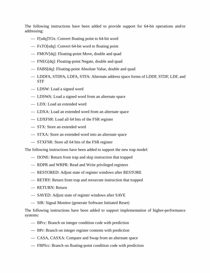
nd/or
nd
ance
The following instructions have been added to provide support for 64-bit operations aaddressing:
— F[sdq]TOx: Convert floating point to 64-bit word
— FxTO[sdq]: Convert 64-bit word to floating point
— FMOV[dq]: Floating-point Move, double and quad
— FNEG[dq]: Floating-point Negate, double and quad
— FABS[dq]: Floating-point Absolute Value, double and quad
— LDDFA, STDFA, LDFA, STFA: Alternate address space forms of LDDF, STDF, LDF, aSTF
— LDSW: Load a signed word
— LDSWA: Load a signed word from an alternate space
— LDX: Load an extended word
— LDXA: Load an extended word from an alternate space
— LDXFSR: Load all 64 bits of the FSR register
— STX: Store an extended word
— STXA: Store an extended word into an alternate space
— STXFSR: Store all 64 bits of the FSR register
The following instructions have been added to support the new trap model:
— DONE: Return from trap and skip instruction that trapped
— RDPR and WRPR: Read and Write privileged registers
— RESTORED: Adjust state of register windows after RESTORE
— RETRY: Return from trap and reexecute instruction that trapped
— RETURN: Return
— SAVED: Adjust state of register windows after SAVE
— SIR: Signal Monitor (generate Software Initiated Reset)
The following instructions have been added to support implementation of higher-performsystems:
— BPcc: Branch on integer condition code with prediction
— BPr: Branch on integer register contents with prediction
— CASA, CASXA: Compare and Swap from an alternate space
— FBPfcc: Branch on floating-point condition code with prediction

ruc-
be
gis-
e regis-
ion).
eakn nearlynstanta-
— FLUSHW: Flush windows
— FMOVcc: Move floating-point register if condition code is satisfied
— FMOVr: Move floating-point register if integer register contents satisfy condition
— LDQF(A), STQF(A): Load/Store Quad Floating-point (in an alternate space)
— MOVcc: Move integer register if condition code is satisfied
— MOVr: Move integer register if register contents satisfy condition
— MULX: Generic 64-bit multiply
— POPC: Population Count
— PREFETCH, PREFETCHA: Prefetch Data
— SDIVX, UDIVX: Signed and Unsigned 64-bit divide
The definitions of the following instructions have changed:
— IMPDEPn: Implementation-Dependent instructions (replace SPARC-V8 CPop insttions)
The following instruction was added to support memory synchronization:
— MEMBAR: Memory barrier
The following instructions have been deleted:
— Coprocessor loads and stores
— RDTBR and WRTBR: TBR no longer exists. It has been replaced by TBA, which canread/written with RDPR/WRPR instructions.
— RDWIM and WRWIM: WIM no longer exists. WIM has been subsumed by several reter-window state registers.
— RDPSR and WRPSR: PSR no longer exists. It has been replaced by several separatters which are read/written with other instructions.
— RETT: Return from trap (replaced by DONE/RETRY).
— STDFQ: Store Double from Floating-point Queue (replaced by the RDPR FQ instruct
K.8 Memory Model
SPARC-V9 defines a new memory model called Relaxed Memory Order (RMO). This very wmodel allows the CPU hardware to schedule memory accesses such as loads and stores iany order, as long as the program computes the correct answer. Hence, the hardware can i
ading to
uc--
an. O.
ch-Pro-
neously adjust to resource contentions and schedule accesses in the most efficient order, lemuch faster memory operations and better performance.
(This Bibliography is not a part of SPARC-V9/R1.4.5,<Italic>The SPARC Architecture Manual;
it is included for information only.)
Bibliography
General References
For general information, see the following:
-----. The SPARC Architecture Manual, Version 8, Prentice-Hall, Inc., 1992.
Boney, Joel [1992]. “SPARC Version 9 Points the Way to the Next Generation RISC,”SunWorld,October 1992, pp. 100-105.
Catanzaro, Ben, ed.The SPARC Technical Papers, Springer-Verlag, 1991.
Cmelik, R. F., S. I. Kong, D. R. Ditzel, and E. J. Kelly, “An Analysis of MIPS and SPARC Instrtion Set Utilization on the SPEC Benchmarks,”Proceedings of the Fourth International Symposium on Architectural Support for Programming Languages and Operating Systems, April 8-11,1991.
Dewar, R. B. K. and M. Smosna.Microprocessors: A Programmer’s View, McGraw-Hill, Inc.,1990.
Ditzel, David R. [1993]. “SPARC Version 9: Adding 64-Bit Addressing and Robustness toExisting RISC Architecture.” Videotape available from University Video Communications, PBox 5129, Stanford, CA, 94309.
Garner, R. B. [1988]. “SPARC: The Scalable Processor Architecture,”SunTechnology, vol. 1, no.3, Summer, 1988; also appeared in M. Hall and J. Barry (eds.),The SunTechnology Papers,Springer-Verlag, 1990, pp. 75-99.
Garner, R. B., A. Agrawal, F. Briggs, E. W. Brown, D. Hough, W. N. Joy, S. Kleiman, S. Munick, M. Namjoo, D. Patterson, J. Pendleton, K. G. Tan, and R. Tuck [1988]. “The Scalablecessor Architecture (SPARC),” 33rd AnnualIEEE Computer Conference (COMPCON), February,1988, San Francisco, CA.
This bibliography is informative only.
It is not part of the SPARC-V9 specification.

Y,
ess,
,
essorsive and
ction
em-
mory
Con-
Hennessy, J. and D. Patterson.Computer Architecture: A Quantitative Approach, Morgan Kauf-man Publishers, Inc., San Mateo, CA. 1990.
IEEE Standard for Binary Floating-Point Arithmetic, IEEE Std 754-1985, IEEE, New York, N1985.
Katevenis, M. [1983]. Reduced Instruction Set Computer Architectures forVLSI, Ph.D. disserta-tion, Computer Science Div., Univ. of California, Berkeley, 1983; also published by M.I.T. PrCambridge, MA, 1985.
Kleiman, S. and D. Williams [1988]. “SunOS on SPARC,”33rd AnnualIEEE Comp. Conf. (COM-PCON), February, 1988, San Francisco, CA; also appeared in M. Hall and J. Barry (eds.)TheSunTechnology Papers, Springer-Verlag, 1990, pp. 13-27.
Muchnick, S. [1988]. “Optimizing Compilers for SPARC,”SunTechnology, Summer 1988, pp. 64-71; also appeared in W. Stallings (ed.),Reduced Instruction Set Computers(2nd edition), IEEEComputer Society Press, 1990, pp. 160-173, and in M. Hall and J. Barry (eds.),The SunTechnol-ogy Papers, Springer-Verlag, 1990, pp. 41-68.
Patterson, D. [1985]. “Reduced Instruction Set Computers,”Communications of theACM, vol. 28,no. 1, January, 1985.
Patterson, D., and D. R. Ditzel, “The Case for the Reduced Instruction Set Computer,”ComputerArchitecture News, vol 8, no. 7, 1980.
Memory Model References
The concept of a memory model has become a significant one as shared memory multiprocare more widely used. The issues are complex and interesting, and have created an actextensive literature. A partial annotated list of references is as follows:
Collier, W. W.Reasoning About Parallel Architectures, Prentice Hall, 1992.
Provides a mathematical framework for the study of parallel processors and their interawith memory.
Dill, David, Seungjoon Park, and Andreas G. Nowatzyk, “Formal Specification of Abstract Mory Models” inResearch on Integrated Systems: Proceedings of the 1993 Symposium, Ed. Gaet-ano Borriello and Carl Ebeling, MIT Press, 1993.
Describes an application of software tools to the verification of the TSO and PSO memodels.
Gharachorloo, K., D. Lenoski, J. Laudon, P. Gibbon, A. Gupta, and J. Hennessy. “Memorysistency and Event Ordering in Scalable Shared-Memory Multiprocessors,”Proceedings of the17th Annual International Symposium on Computer Architecture, May 1990, pp. 15-29.
Provides an overview of contemporary research in memory models.
ent
about
tencye
emory
ro-
ry sys-
ciated
ory
mod-
port
ssing
ting
Gharachorloo, K., S. Adve, A. Gupta, J. Hennessy, and M. Hill. “Programming for DifferMemory Consistency Models,”Journal of Parallel and Distributed Processing, 15:4, August1992.
This paper proposes a new programming model which allows programmers to reasonprograms that have not been reduced to sequential consistency.
Gharachorloo, K., A. Gupta, and J. Hennessy, “Performance Evaluation of Memory ConsisModels for Shared Memory Multiprocessors,”Proceedings of the 4th International Conferencon Architectural Support for Programming Languages and Operating Systems, pp. 245-257,ACM, New York, 1991.
This paper discusses the performance benefits that can be obtained when a relaxed mmodel is used in a shared-memory model processor.
Lamport, Leslie. “How to Make a Multiprocessor Computer That Correctly Executes Multipcess Programs,” IEEE Transactions on Computers, C-28, 9, September 1979, pp. 690-691.
Defines sequential consistency and shows how it can be used in simple shared-memotems.
Reynal, M.Algorithms for Mutual Exclusion, MIT Press, 1986.
Provides an overview of the mutual exclusion problem and the extensive literature assowith it.
Scheurich, C., and M. Dubois. “Dependency and Hazard Resolution in Multiprocessors,”Pro-ceedings of the 14th International Symposium on Computer Architecture, pp. 234-243, IEEE CSPress, Los Alamitos, CA, 1987.
Sindhu, Predeep, Jean-Marc Frailong, and Michel Ceklov. “Formal Specification of MemModels,” Xerox Palo Alto Research Center Report CSL-91-11, December 1991.
Introduces the formal framework used to define the SPARC-V8 TSO and PSO memoryels.
Treiber, R. Kent. “Systems Programming: Coping with Parallelism,” IBM Research ReRJ5118 (53162), 1986.
Provides an overview of the operational issues for systems programming in a multiproceenvironment.
Prefetching
Callahan, D., K. Kennedy, A. Porterfield. “Software Prefetching,”Proceedings of the FourthInternational Conference on Architectural Support for Programming Languages and OperaSystems, April 1991, pp. 40-52.
ch-m-
Mowry, T., M. Lam, and A. Gupta. “Design and Evaluation of a Compiler Algorithm for Prefeting.” Proceedings of the Fifth International Conference on Architectural Support for Programing Languages and Operating Systems, October 1992, pp. 62-73.
Aa field of instructions, 66, 138, 141, 144, 147, 148, 152ABI, seeSPARC-V9 Application Binary Interface (ABI)accrued exception (aexc) field of FSR register, 46, 48, 100, 247, 254activation record, seestack frameADD instruction, 137, 299ADDC instruction, 137ADDcc instruction, 137, 222, 299ADDCcc instruction, 137address, 120
aliased, 120physical, 120, 281virtual, 120, 281
address, 295address aliases, 281address mask (AM) field of PSTATE register, 53, 151, 172, 215address space, 4, 281, 282address space identifier (ASI), 9, 16, 17, 50, 63, 67, 69, 73, 120, 121, 174, 179, 207, 227, 254, 283, 317, 341
architecturally specified, 122restricted, 74, 122, 254unrestricted, 74, 122, 254
address space identifier (ASI) register, 16, 21, 50, 56, 73, 89, 122, 157, 176, 181, 183, 207, 227, 232, 235, 245,316
addressing conventions, 17, 70addressing modes, 4ADDX instruction (SPARC-V8), 137ADDXcc instruction (SPARC-V8), 137aexc, seeaccrued exception (aexc) field of FSR registerAG, seealternate globals enable (AG) field of PSTATE registeraggregate data values, seedata aggregatesalias
address, 120floating-point registers, 36
alignment, 304data (load/store), 17, 69, 121doubleword, 17, 69, 121extended-word, 69halfword, 17, 69, 121instructions, 17, 69, 121integer registers, 179, 181memory, 121quadword, 17, 69, 121stack pointer, 304word, 17, 69, 121
alternate address space, 207alternate global registers, 15, 30, 30, 316

alternate globals enable (AG) field of PSTATE register, 30, 31, 54alternate space instructions, 18, 50, 341AM, seeaddress mask (AM) field of PSTATE registerancillary state registers (ASRs), 18, 35, 36, 60, 214, 215, 244, 245, 252, 253, 292, 321AND instruction, 184ANDcc instruction, 184, 299ANDN instruction, 184, 299ANDNcc instruction, 184annul bit, 35, 138
in conditional branches, 141annulled branches, 138application program, 9, 14, 16, 30, 46, 47, 50, 61, 104, 341architectural extensions, 7, 321arguments to a subroutine, 302arithmetic overflow, 41ASI register, seeaddress space identifier (ASI) registerASI, seeaddress space identifier (ASI)ASI_AS_IF_USER_PRIMARY, 75, 123, 254, 287, 316ASI_AS_IF_USER_PRIMARY_LITTLE, 75, 123, 254, 287, 316ASI_AS_IF_USER_SECONDARY, 75, 123, 254, 287ASI_AS_IF_USER_SECONDARY_LITTLE, 75, 123, 254, 287ASI_NUCLEUS, 75, 75, 122, 254, 287ASI_NUCLEUS_LITTLE, 75, 122, 254, 287ASI_PRIMARY, 73, 75, 75, 122, 123, 254, 287ASI_PRIMARY_LITTLE, 52, 75, 122, 254, 287ASI_PRIMARY_NOFAULT, 75, 75, 123, 254, 284, 287ASI_PRIMARY_NOFAULT_LITTLE, 75, 254ASI_SECONDARY, 75, 75, 123, 254, 287, 317ASI_SECONDARY_LITTLE, 75, 254, 287, 317ASI_SECONDARY_NOFAULT, 75, 75, 123, 254, 284, 287ASI_SECONDARY_NOFAULT_LITTLE, 75, 254, 287asr_reg, 292assembler
synthetic instructions, 297assigned value
implementation-dependent, 252async_data_error exception, 113, 133, 153, 174, 177, 179, 181, 182, 183, 226, 228, 230, 232, 234, 236atomic, 130, 230, 232
memory operations, 127, 130atomic load-store instructions, 69, 152
compare and swap, 98, 152load-store unsigned byte, 182, 234, 235load-store unsigned byte to alternate space, 183swapr register with alternate space memory, 235swapr register with memory, 152, 234
atomicity, 121, 224, 258automatic variables, 302
BBA instruction, 147, 278BCC instruction, 146, 278BCLR synthetic instruction, 299BCS instruction, 146, 278

BE instruction, 146, 278Berkeley RISCs, xiv, 5BG instruction, 146, 278BGE instruction, 146, 278BGU instruction, 146, 278bibliography, 345Bicc instructions, 35, 42, 146, 273, 278big-endian btye order, 9big-endian byte order, 17, 52, 70binary compatibility, 6bit vector concatenation, 3BL instruction, 278BLE instruction, 146, 278BLEU instruction, 146, 278BN instruction, 146, 147, 209, 278, 297BNE instruction, 146, 278BNEG instruction, 146, 278BPA instruction, 148, 278BPCC instruction, 148, 278BPcc instructions, 35, 41, 42, 66, 67, 148, 209BPCS instruction, 148, 278BPE instruction, 148, 278BPG instruction, 148, 278BPGE instruction, 148, 278BPGU instruction, 148, 278BPL instruction, 148, 278BPLE instruction, 148, 278BPLEU instruction, 148, 278BPN instruction, 148, 278BPNE instruction, 148, 278BPNEG instruction, 148, 278BPOS instruction, 146, 278BPPOS instruction, 148, 278BPr instructions, 35, 66, 67, 138, 273, 278BPVC instruction, 148, 278BPVS instruction, 148, 278branch
annulled, 138delayed, 63elimination, 81fcc-conditional, 141, 144icc-conditional, 147prediction bit, 138unconditional, 141, 144, 147, 149with prediction, 5
branch if contents of integer register match condition instructions, 138branch on floating-point condition codes instructions, 140branch on floating-point condition codes with prediction instructions, 143branch on integer condition codes instructions, 146branch on integer condition codes with prediction instructions, 148BRGEZ instruction, 138BRGZ instruction, 138BRLEZ instruction, 138BRLZ instruction, 138
BRNZ instruction, 138BRZ instruction, 138BSET synthetic instruction, 299BTOG synthetic instruction, 299BTST synthetic instruction, 299BVC instruction, 146, 278BVS instruction, 146, 278byte, 9
addressing, 70, 71data format, 23order, 17, 70order, big-endian, 17, 52order, implicit, 52order, little-endian, 17, 52
CC condition code bit, seecarry (C) bit of condition fields of CCRcache
coherence in RED_state, 92data, 125in RED_state, 92instruction, 125memory, 253miss, 209non-consistent instruction cache, 125system, 6
call chainwalking, 303
CALL instruction, 19, 33, 34, 35, 151, 172, 302, 304CALL synthetic instruction, 297CANRESTORE, seerestorable windows (CANRESTORE) registerCANSAVE, seesavable windows (CANSAVE) registercarry (C) bit of condition fields of CCR, 41CAS synthetic instruction, 127, 299CASA instruction, 98, 130, 152, 182, 183, 234, 235, 299CASX synthetic instruction, 127, 130, 299CASXA instruction, 98, 130, 152, 182, 183, 234, 235, 299catastrophic_error exception, 89, 91, 98, 99, 113, 114, 115cc0 field of instructions, 66, 144, 148, 159, 195cc1 field of instructions, 66, 144, 148, 159, 195cc2 field of instructions, 66, 195CCR, seecondition codes (CCR) registercertificate of compliance, 8cexc, seecurrent exception (cexc) field of FSR registerCLE, seecurrent_little-endian (CLE) field of PSTATE registerclean register window, 9, 33, 58, 60, 82, 86, 88, 114, 217clean windows (CLEANWIN) register, 58, 60, 82, 83, 86, 87, 88, 211, 242, 259clean_window exception, 60, 82, 87, 98, 101, 114, 218, 256clock cycle, 51clock-tick register (TICK), 51, 116, 211, 242, 257CLR synthetic instruction, 299CMP synthetic instruction, 233, 297coherence, 120, 258
memory, 121, 224unit, memory, 122
compare and swap instructions, 98, 152comparison instruction, 76, 233compatibility note, 4compatibility with SPARC-V8, 4, 19, 30, 40, 43, 54, 58, 76, 78, 85, 104, 114, 115, 116, 121, 142, 145, 160,
170, 171, 174, 179, 181, 187, 215, 224, 226, 230, 232, 233, 237, 239, 241, 245, 322, 336compatibility with SPARC-V9, 137compliance, 8
certificate of, 8certification process, 8Level I, 7Level II, 8
compliant SPARC-V9 implementation, 7concatenation of bit vectors, 3concurrency, 15cond field of instructions, 66, 141, 144, 147, 148, 189, 195condition codes, 153
floating-point, 141integer, 41
condition codes (CCR) register, 21, 89, 137, 157, 202, 245conditional branches, 141, 144, 147conditional move instructions, 20conforming SPARC-V9 implementation, 7const22 field of instructions, 170constants
generating, 220contexts
Nucleus, 122, 287control and status registers, 35control-transfer instructions (CTIs), 19, 157conventions
software, 301convert between floating-point formats instructions, 162, 248convert floating-point to integer instructions, 161, 250convert integer to floating-point instructions, 163coprocessor, 322counter field of TICK register, 51CPopn instructions (SPARC-V8), 171, 322cross-domain call, 316CTI, seecontrol-transfer instructions (CTIs)current exception (cexc) field of FSR register, 44, 46, 48, 84, 115, 247, 254current window, 9current window pointer (CWP) register, 9, 15, 21, 33, 56, 58, 58, 60, 82, 87, 89, 157, 169, 211, 217, 218, 242,
259current_little_endian (CLE) field of PSTATE register, 52, 52, 122CWP, seecurrent window pointer (CWP) register
Dd16hi field of instructions, 66, 138d16lo field of instructions, 66, 138data access
RED_state, 92

data aggregateargument passed by value, 302examples of, 302
data alignment, seealignmentdata cache, 125data flow order constraints
memory reference instructions, 124register reference instructions, 124
data formatsbyte, 23doubleword, 23extended word, 23halfword, 23quadword, 23tagged word, 23word, 23
data memory, 131data types, 23
floating-point, 23signed integer, 23unsigned integer, 23
data_access_error exception, 114, 153, 174, 177, 179, 181, 182, 183, 226, 228, 230, 232, 234, 236data_access_exception exception, 114, 153, 174, 177, 179, 181, 182, 183, 226, 228, 230, 232, 234, 236data_access_MMU_miss exception, 114, 153, 174, 177, 179, 181, 182, 183, 210, 226, 228, 230, 232, 234, 236,
256data_access_protection exception, 114, 153, 175, 177, 179, 181, 182, 183, 226, 228, 230, 232data_protection exception, 234, 236DEC synthetic instruction, 299DECcc synthetic instruction, 299deferred trap, 95, 95, 96, 99, 254
avoiding, 96floating-point, 212
deferred-trap queue, 95floating-point (FQ), 47, 61, 96, 211, 243integer unit, 61
Dekker's algorithm, 326delay instruction, 19, 35, 138, 141, 144, 150, 157, 216, 302, 306delayed branch, 63delayed control transfer, 35, 138deprecated instructions
BCC, 146BCS, 146BE, 146BG, 146BGE, 146BGU, 146Bicc, 146BLE, 146BLEU, 146BN, 146BNE, 146BNEG, 146BPOS, 146BVC, 146

BVS, 146FBE, 140FBfcc, 140FBG, 140FBGE, 140FBL, 140FBLE, 140FBLG, 140FBN, 140FBNE, 140FBO, 140FBU, 140FBUE, 140FBUGE, 140FBUL, 140FBULE, 140LDDA , 180LDFSR, 173MULScc, 202SDIV, 154SDIVcc, 154SMULcc, 200STFSR, 225SWAP, 234SWAPA, 235TSUBccTV, 237, 238UDIVcc, 154UMULcc, 200
destination register, 13dirty bits, seelower and upper registers dirty (DL and DU) fields of FPRS registerdisp19 field of instructions, 66, 144, 148disp22 field of instructions, 66, 141, 147disp30 field of instructions, 66, 151disrupting traps, 95, 96, 97, 98, 254divide instructions, 19, 154, 199divide-by-zero mask (DZM) bit of TEM field of FSR register, 48division_by_zero exception, 77, 98, 104, 114, 156, 199division-by-zero accrued (dza) bit of aexc field of FSR register, 49division-by-zero current (dzc) bit of cexc field of FSR register, 49DL, seelower registers dirty (DL) field of FPRS registerDONE instruction, 20, 41, 42, 89, 91, 95doublet, 9doubleword, 9, 17, 69, 121
addressing, 70, 72in memory, 35
doubleword data format, 23DU, seeupper registers dirty (DU) field of FPRS registerdza, seedivision-by-zero accrued (dza) bit of aexc field of FSR registerdzc, seedivision-by-zero current (dzc) bit of cexc field of FSR registerDZM, seedivide-by-zero mask (DZM) bit of TEM field of FSR register
Eemulating multiple unsigned condition codes, 81
enable floating-point (FEF) field of FPRS register, 42, 53, 84, 99, 114, 142, 145, 174, 176, 226, 227, 243enable floating-point (PEF) field of PSTATE register, 42, 53, 84, 99, 114, 142, 145, 174, 176, 226, 227, 309enable RED_state (RED) field of PSTATE register, 91error_state processor state, 56, 90, 91, 94, 105, 106, 109, 110, 111, 112, 117, 255exceptions, 21, 89
async_data_error, 113, 133, 153, 174, 177, 179, 181, 182, 183, 226, 228, 230, 232, 234, 236catastrophic, 98catastrophic_error, 89, 91, 99, 113, 114, 115clean_window, 60, 82, 87, 98, 101, 114, 218, 256data_access_error, 114, 153, 174, 177, 179, 181, 182, 183, 226, 228, 230, 232, 234, 236data_access_exception, 114, 153, 174, 177, 179, 181, 182, 183, 226, 228, 230, 232, 234, 236data_access_MMU_miss, 114, 153, 174, 177, 179, 181, 182, 183, 210, 226, 228, 230, 232, 234, 236, 256data_access_protection, 114, 153, 175, 177, 179, 181, 226, 228, 230, 232data_protection, 234, 236division_by_zero, 77, 98, 104, 114, 156, 199externally_initiated_reset (XIR), 56, 108, 110fill_n_normal, 98, 114, 216, 218fill_n_other, 98, 114, 216, 218floating-point, 10, 99fp_disabled, 16, 42, 84, 98, 114, 142, 145, 158, 160, 161, 162, 163, 164, 165, 166, 174, 176, 177, 191,
193, 197, 226, 227, 228, 309fp_exception, 45fp_exception_ieee_754, 44, 48, 99, 100, 104, 115, 158, 160, 161, 162, 163, 165, 166, 247fp_exception_other, 40, 47, 61, 85, 104, 115, 158, 160, 161, 162, 163, 164, 165, 166, 174, 177, 191, 193,
213, 226, 228, 247illegal_instruction, 35, 47, 58, 85, 115, 133, 139, 150, 157, 168, 170, 171, 174, 179, 181, 197, 198, 205,
212, 213, 215, 219, 226, 229, 230, 231, 232, 241, 243, 245, 254, 255, 256implementation_dependent_n, 91, 104, 255instruction_access, 97instruction_access_error, 98, 115, 133instruction_access_exception, 115, 133instruction_access_MMU_miss, 115, 133internal_processor_error, 91, 115, 133invalid_exception, 161LDDF_mem_address_not_aligned, 70, 98, 115, 174, 177, 226, 228, 257LDQF_mem_address_not_aligned, 70, 116, 174, 177, 257mem_address_not_aligned, 69, 98, 116, 153, 172, 174, 177, 179, 181, 216, 226, 228, 230, 232, 234, 236persistence, 100power_on_reset (POR), 108, 116privileged_action, 51, 73, 97, 116, 153, 176, 177, 181, 183, 215, 227, 228, 232, 236privileged_instruction (SPARC-V8), 116privileged_opcode, 98, 116, 157, 212, 215, 219, 243, 245r_register_access_error (SPARC-V8), 115software_initiated reset (SIR), 105software_initiated_reset, 97software_initiated_reset (SIR), 97, 111, 116, 223spill_n_normal, 98, 116, 169, 218spill_n_other, 116, 169, 218STDF_mem_address_not_aligned, 70, 98, 116, 226, 228, 257STQF_mem_address_not_aligned, 70, 116, 226, 228, 257tag_overflow, 77, 98, 104, 117, 237, 239trap_instruction, 98, 117, 241unimplemented_LDD, 98, 117, 179, 181, 257unimplemented_STD, 98, 117, 230, 232, 257

watchdog_reset (WDR), 108window_fill, 58, 59, 60, 82, 216, 305window_overflow, 301window_spill, 58, 60, 305
exceptions, also seetrap typesexecute protection, 282execute unit, 123execute_state, 90, 105, 106, 110, 111, 117extended word, 10extended word addressing, 70, 72extended word data format, 23extensions
architectural, 7, 321externally_initiated_reset (XIR), 56, 91, 93, 97, 108, 110, 111
Ff registers, 16, 36, 100, 247, 255FABSd instruction, 164, 275, 276, 277FABSq instruction, 164, 275, 276, 277FABSs instruction, 164, 275FADDd instruction, 158, 275FADDq instruction, 158, 275FADDs instruction, 158, 275FBA instruction, 141, 278FBE instruction, 140, 278FBfcc instructions, 35, 43, 84, 99, 114, 140, 142, 273, 278FBG instruction, 140, 278FBGE instruction, 140, 278FBL instruction, 140, 278FBLE instruction, 140, 278FBLG instruction, 140, 278FBN instruction, 140, 141, 278FBNE instruction, 140, 278FBO instruction, 140, 278FBPA instruction, 143, 144, 278FBPcc instructions, 66FBPE instruction, 143, 278FBPfcc instructions, 35, 43, 66, 67, 84, 99, 142, 143, 273, 278FBPG instruction, 143, 278FBPGE instruction, 143, 278FBPL instruction, 143, 278FBPLE instruction, 143, 278FBPLG instruction, 143, 278FBPN instruction, 143, 144, 278FBPNE instruction, 143, 278FBPO instruction, 143, 278FBPU instruction, 143, 278FBPUE instruction, 143, 278FBPUG instruction, 143, 278FBPUGE instruction, 143, 278FBPUL instruction, 143, 278FBPULE instruction, 143, 278FBU instruction, 140, 278
FBUE instruction, 140, 278FBUG instruction, 140, 278FBUGE instruction, 140, 278FBUL instruction, 140, 278FBULE instruction, 140, 278fcc, seefloating-point condition codes (fcc) fields of FSR registerfcc-conditional branches, 141, 144fccN, 10FCMP* instructions, 43, 159FCMPd instruction, 159, 248, 277FCMPE* instructions, 43, 159FCMPEd instruction, 159, 248, 277FCMPEq instruction, 159, 248, 277FCMPEs instruction, 159, 248, 277FCMPq instruction, 159, 248, 277FCMPs instruction, 159, 248, 277fcn field of instructions, 157, 206FDIVd instruction, 165, 275FDIVq instruction, 165, 275FDIVs instruction, 165, 275FdMULq instruction, 165, 275FdTOi instruction, 161, 250, 275FdTOq instruction, 162, 248, 275FdTOs instruction, 162, 248, 275FdTOx instruction, 161, 275, 276, 277FEF, seeenable floating-point (FEF) field of FPRS registerfill register window, 33, 58, 59, 82, 83, 86, 87, 88, 114, 217, 218, 219, 316fill_n_normal exception, 98, 114, 216, 218fill_n_other exception, 98, 114, 216, 218FiTOd instruction, 163, 275FiTOq instruction, 163, 275FiTOs instruction, 163, 275floating-point add and subtract instructions, 158floating-point compare instructions, 43, 159, 159, 248floating-point condition code bits, 141floating-point condition codes (fcc) fields of FSR register, 43, 46, 100, 141, 144, 159, 247, 292floating-point data type, 23floating-point deferred-trap queue (FQ), 47, 61, 96, 211, 212, 243, 254floating-point enable (FEF) field of FPRS register, 309floating-point exception, 10, 99floating-point move instructions, 164floating-point multiply and divide instructions, 165floating-point operate (FPop) instructions, 10, 20, 36, 45, 48, 67, 84, 99, 114, 115, 174floating-point queue, seefloating-point deferred-trap queue (FQ)floating-point registers, 40, 247, 255, 304floating-point registers state (FPRS) register, 42, 215, 245floating-point square root instructions, 166floating-point state (FSR) register, 43, 48, 50, 174, 225, 226, 247, 250, 254floating-point trap type (ftt) field of FSR register, 10, 43, 45, 48, 61, 84, 85, 115, 212, 226, 247floating-point trap types
fp_disabled, 53FPop_unfinished, 85FPop_unimplemented, 85hardware_error, 10, 45, 47
IEEE_754_exception, 10, 46, 46, 48, 50, 100, 115, 247invalid_fp_register, 10, 40, 46, 158, 160, 161, 162, 163, 164, 165, 166, 174, 177, 191, 193, 226, 228numeric values, 45sequence_error, 45, 46, 47, 61, 212, 213unfinished_FPop, 10, 46, 46, 50, 247, 253unimplemented_FPop, 10, 46, 46, 50, 85, 191, 212, 247, 253
floating-point trapsdeferred, 212precise, 212
floating-point unit (FPU), 10, 16FLUSH instruction, 131, 167, 253, 258, 308, 324
in multiprocess environment, 132flush instruction memory instruction, 167, 324FLUSH latency, 258flush register windows instruction, 169FLUSHW instruction, 20, 83, 86, 87, 116, 169, 303FMOVA instruction, 188FMOVCC instruction, 188FMOVcc instructions, 41, 42, 43, 66, 67, 80, 84, 188, 191, 196, 197, 278FMOVccd instruction, 277FMOVccq instruction, 277FMOVccs instruction, 277FMOVCS instruction, 188FMOVd instruction, 164, 275, 276, 277FMOVE instruction, 188FMOVFA instruction, 188FMOVFE instruction, 188FMOVFG instruction, 188FMOVFGE instruction, 188FMOVFL instruction, 188FMOVFLE instruction, 188FMOVFLG instruction, 188FMOVFN instruction, 188FMOVFNE instruction, 188FMOVFO instruction, 188FMOVFU instruction, 188FMOVFUE instruction, 188FMOVFUG instruction, 188FMOVFUGE instruction, 188FMOVFUL instruction, 188FMOVFULE instruction, 188FMOVG instruction, 188FMOVGE instruction, 188FMOVGU instruction, 188FMOVL instruction, 188FMOVLE instruction, 188FMOVLEU instruction, 188FMOVN instruction, 188FMOVNE instruction, 188FMOVNEG instruction, 188FMOVPOS instruction, 188FMOVq instruction, 164, 275, 276, 277FMOVr instructions, 67, 84, 192FMOVRGEZ instruction, 192

FMOVRGZ instruction, 192FMOVRLEZ instruction, 192FMOVRLZ instruction, 192FMOVRNZ instruction, 192FMOVRZ instruction, 192FMOVs instruction, 164, 275FMOVVC instruction, 188FMOVVS instruction, 188FMULd instruction, 165, 275FMULq instruction, 165, 275FMULs instruction, 165, 275FNEGd instruction, 164, 275, 276, 277FNEGq instruction, 164, 275, 276, 277FNEGs instruction, 164, 275formats
instruction, 63fp_disabled floating-point trap type, 16, 42, 53, 84, 98, 114, 142, 145, 158, 160, 161, 162, 163, 164, 165, 166,
174, 176, 177, 191, 193, 197, 226, 227, 228, 309fp_exception exception, 45, 48fp_exception_ieee_754 exception, 44, 48, 99, 100, 104, 115, 158, 160, 161, 162, 163, 165, 166, 247fp_exception_other exception, 40, 47, 61, 85, 104, 115, 158, 160, 161, 162, 163, 164, 165, 166, 174, 177, 191,
193, 212, 213, 226, 228, 247FPop instructions, seefloating-point operate (FPop) instructionsFPop_unimplemented floating-point trap type, 85FPop1 instructions, 10FPop2 instructions, 10FPRS, seefloating-point register state (FPRS) registerFPU, seefloating-point unitFQ, seefloating-point deferred-trap queue (FQ)FqTOd instruction, 162, 248, 275FqTOi instruction, 161, 250, 275FqTOs instruction, 162, 248, 275FqTOx instruction, 161, 275, 276, 277frame pointer register, 302freg, 292FsMULd instruction, 165, 275FSQRTd instruction, 166, 275FSQRTq instruction, 166, 275FSQRTs instruction, 166, 275FsTOd instruction, 162, 248, 275FsTOi instruction, 161, 250, 275FsTOq instruction, 162, 248, 275FsTOx instruction, 161, 275, 276, 277FSUBd instruction, 158, 275FSUBq instruction, 158, 275FSUBs instruction, 158, 275ftt, seefloating-point trap type (ftt) field of FSR registerfunction return value, 302functional choice
implementation-dependent, 252FxTOd instruction, 163, 275, 276, 277FxTOq instruction, 163, 275, 276, 277FxTOs instruction, 163, 275, 276, 277

Ggenerating constants, 220global registers, 4, 15, 30, 30, 30, 303
Hhalfword, 10, 17, 69, 121
addressing, 70, 72data format, 23
halt, 105hardware
dependency, 251traps, 101
hardware_error floating-point trap type, 10, 45, 47has, 7hexlet, 10
Ii field of instructions, 66, 137, 154, 167, 169, 172, 173, 176, 178, 180, 182, 183, 184, 195, 198, 199, 200, 202,
205, 206, 214, 216I/O, seeinput/output (I/O)i_or_x_cc, 292icc field of CCR register, 41, 42, 137, 147, 149, 155, 156, 184, 196, 200, 202, 203, 233, 237, 241icc-conditional branches, 147IE, seeinterrupt enable (IE) field of PSTATE registerIEEE Std 754-1985, 10, 15, 44, 46, 48, 50, 85, 247, 249, 250, 253, 254IEEE_754_exception floating-point trap type, 10, 46, 46, 48, 50, 100, 115, 247IER register (SPARC-V8), 245illegal_instruction exception, 35, 47, 58, 85, 115, 133, 139, 150, 157, 168, 170, 171, 174, 179, 181, 197, 198,
205, 210, 212, 213, 215, 219, 226, 229, 230, 231, 232, 241, 243, 245, 254, 255, 256ILLTRAP instruction, 115, 170, 273imm_asi field of instructions, 67, 73, 152, 173, 176, 178, 180, 182, 183, 206imm22 field of instructions, 67IMPDEPn instructions, seeimplementation-dependent (IMPDEPn) instructionsIMPL, 171impl field of VER register, 45impl_dep (PID) fields of PSTATE register, 52implementation, 10implementation dependency, 7, 251implementation note, 4implementation number (impl) field of VER register, 57implementation_dependent_n exception, 91, 104, 115, 255implementation-dependent, 10
assigned value (a), 252functional choice (c), 252total unit (t), 252trap, 108value (v), 252
implementation-dependent (IMPDEPn) instructions, 85, 171, 257, 321implicit
ASI, 73byte order, 52

in registers, 15, 30, 33, 217, 301INC synthetic instruction, 299INCcc synthetic instruction, 299inexact accrued (nxa) bit of aexc field of FSR register, 49, 250inexact current (nxc) bit of cexc field of FSR register, 48, 49, 249, 250inexact mask (NXM) bit of TEM field of FSR register, 48, 48inexact quotient, 154, 155infinity , 250initiated, 11input/output (I/O), 6, 18input/output (I/O) locations, 120, 121, 130, 253, 258
order, 121value semantics, 121
instructionaccess in RED_state, 92alignment, 17, 69, 121cache, 125dispatch, 98execution, 98fetch, 69formats, 4, 63memory, 131reordering, 124
instruction fields, 11a, 66, 138, 141, 147, 148, 152cc0, 66, 144, 148, 159, 195cc1, 66, 144, 148, 159, 195cc2, 66, 195cond, 66, 141, 144, 147, 148, 189, 195const22, 170d16hi, 66, 138d16lo, 66, 138disp19, 66, 144, 148disp22, 66, 141, 147disp30, 66, 151fcn, 157, 206i, 66, 137, 154, 167, 169, 172, 173, 176, 178, 180, 182, 183, 184, 195, 198, 199, 200, 202, 205, 206, 214,
216imm_asi, 67, 73, 152, 173, 176, 178, 180, 206imm22, 67mmask, 67, 224op3, 67, 137, 152, 154, 157, 167, 169, 172, 173, 176, 178, 180, 182, 183, 184, 199, 200, 202, 206, 211,
214, 216opf, 67, 158, 159, 161, 162, 163, 164, 165, 166opf_cc, 67, 189opf_low, 67, 189, 192p, 67, 138, 139, 144, 148rcond, 67, 138, 192, 198rd, 13, 68, 137, 152, 154, 158, 161, 162, 163, 164, 165, 166, 172, 173, 176, 178, 180, 182, 183, 184, 189,
192, 195, 198, 199, 200, 202, 205, 211, 214, 321reg_or_imm, 321reserved, 133rs1, 13, 68, 137, 138, 152, 154, 158, 159, 165, 167, 172, 173, 176, 178, 180, 182, 183, 184, 192, 198,
199, 200, 202, 206, 211, 214, 216, 321

rs2, 13, 68, 137, 152, 154, 158, 159, 161, 162, 163, 164, 165, 166, 167, 172, 173, 176, 178, 180, 182,183, 184, 189, 192, 195, 198, 199, 200, 202, 205, 206, 216
simm10, 68, 198simm11, 68, 195simm13, 68, 137, 154, 167, 172, 173, 176, 178, 180, 182, 183, 184, 199, 200, 202, 205, 206, 216sw_trap#, 68undefined, 171
instruction set architecture, 5, 10, 11instruction_access exception, 97instruction_access_error exception, 98, 115, 133instruction_access_exception exception, 115, 133instruction_access_MMU_miss exception, 115, 133instructions
atomic, 152atomic load-store, 69, 98, 152, 182, 183, 234, 235branch if contents of integer register match condition, 138branch on floating-point condition codes, 140branch on floating-point condition codes with prediction, 143branch on integer condition codes, 146branch on integer condition codes with prediction, 148compare and swap, 98, 152comparison, 76, 233conditional move, 20control-transfer (CTIs), 19, 157convert between floating-point formats, 162, 248convert floating-point to integer, 161, 250convert integer to floating-point, 163divide, 19, 154, 199floating-point add and subtract, 158floating-point compare, 43, 159, 159, 248floating-point move, 164floating-point multiply and divide, 165floating-point operate (FPop), 20, 45, 48, 99, 174floating-point square root, 166flush instruction memory, 167, 324flush register windows, 169implementation-dependent (IMPDEPn), 85, 171jump and link, 19, 172load, 323load floating-point, 69, 173load floating-point from alternate space, 176load integer, 69, 178load integer from alternate space, 180load-store unsigned byte, 98, 152, 182, 234, 235load-store unsigned byte to alternate space, 183logical, 184move floating-point register if condition is true, 188move floating-point register if contents of integer register satisfy condition, 192move integer register if condition is satisfied, 194move integer register if contents of integer register satisfies condition, 198move on condition, 5multiply, 19, 199, 200, 200multiply step, 19, 202prefetch data, 206
read privileged register, 211read state register, 20, 214register window management, 20reserved, 85reserved fields, 133shift, 19, 221software-initiated reset, 223store, 323store floating point, 69store floating-point, 225store floating-point into alternate space, 227store integer, 69, 229, 231subtract, 233swapr register with alternate space memory, 235swapr register with memory, 234synthetic, 297tagged add, 237tagged arithmetic, 19test-and-set, 131timing, 133trap on integer condition codes, 240write privileged register, 242write state register, 244
integer condition codes, seeicc field of CCR registerinteger divide instructions, seedivide instructionsinteger multiply instructions, seemultiply instructionsinteger unit (IU), 11, 11, 15integer unit deferred-trap queue, 61internal_processor_error exception, 91, 115, 133
and RED_state, 93interrupt enable (IE) field of PSTATE register, 54, 96, 99, 115interrupt level, 54interrupt request, 11, 21, 89, 133interrupts, 54invalid accrued (nva) bit of aexc field of FSR register, 49invalid current (nvc) bit of cexc field of FSR register, 49, 250invalid mask (NVM) bit of TEM field of FSR register, 48invalid_exception exception, 161invalid_fp_register floating-point trap type, 10, 40, 46, 158, 160, 161, 162, 163, 164, 165, 166, 174, 177, 191,
193, 226, 228IPREFETCH synthetic instruction, 297ISA, seeinstruction set architectureissue unit, 123, 124issued, 11italic font
in assembly language syntax, 291IU, seeinteger unit
JJMP synthetic instruction, 297JMPL instruction, 19, 33, 35, 116, 172, 216, 297, 304jump and link instruction, 19, 172

LLD instruction (SPARC-V8), 179LDA instruction (SPARC-V8), 181LDD instruction, 35, 98, 117, 178, 257LDDA instruction, 35, 61, 98, 180, 257LDDF instruction, 70, 98, 115, 173LDDF_mem_address_not_aligned exception, 70, 98, 115, 174, 177, 228, 257LDDFA instruction, 70, 98, 176LDF instruction, 173LDFSR instruction, 43, 45, 48, 50, 173LDQF instruction, 70, 116, 173LDQF_mem_address_not_aligned exception, 70, 116, 174, 177, 257LDQFA instruction, 70, 176LDSB instruction, 178LDSBA instruction, 180LDSH instruction, 178LDSHA instruction, 180LDSTUB insruction, 69LDSTUB instruction, 98, 127, 131, 182, 327LDSTUBA instruction, 98, 183LDSW instruction, 178LDSWA instruction, 180LDUB instruction, 178LDUBA instruction, 180LDUH instruction, 178LDUHA instruction, 180LDUW instruction, 178LDUWA instruction, 180LDX instruction, 98, 178LDXA instruction, 98, 180LDXFSR instruction, 43, 45, 48, 50, 173leaf procedure, 11, 82, 304, 304
optimization, 305, 306Level I compliance, 7Level II compliance, 8little-endian byte order, 11, 17, 52load floating-point from alternate space instructions, 176load floating-point instructions, 173load instructions, 69, 323load integer from alternate space instructions, 180load integer instructions, 178LoadLoad MEMBAR relationship, 127, 187loads
non-faulting, 123, 123loads from alternate space, 18, 50, 73, 341load-store alignment, 17, 69, 121load-store instructions, 17, 98
compare and swap, 98, 152load-store unsigned byte, 152, 182, 234, 235load-store unsigned byte to alternate space, 183swapr register with alternate space memory, 235swapr register with memory, 152, 234
LoadStore MEMBAR relationship, 127, 128, 187

local registers, 15, 30, 33, 217, 302, 307logical instructions, 184Lookaside MEMBAR relationship, 187lower registers dirty (DL) field of FPRS register, 42
Mmanual
audience, 1fonts, 3where to start, 1
manufacturer (manuf) field of VER register, 57, 256mask number (mask) field of VER register, 57maximum trap levels (maxtl) field of VER register, 57MAXTL , 54, 90, 106, 223maxtl, seemaximum trap levels (maxtl) field of VER registermay, 11mem_address_not_aligned exception, 69, 98, 116, 153, 172, 174, 177, 179, 181, 216, 226, 228, 230, 232, 234,
236MEMBAR instruction, 67, 76, 121, 125, 126–128, 129, 131, 167, 186, 214, 224, 324membar_mask, 295MemIssue MEMBAR relationship, 187memory
alignment, 121atomicity, 258coherence, 120, 121, 258coherency unit, 122data, 131instruction, 131ordering unit, 121page, 281real, 120, 121stack layout, 304
memory access instructions, 17memory management unit (MMU), 6, 114, 115, 253, 291
address translation, 286ASI input, 283atomic input, 283context, 281Data / Instr input, 283diagram, 283disabled, 207disabling, 282fault address, 288fault status, 288in RED_state, 92memory protection, 286modified statistics, 282, 288NF-Load_violation output, 285No_translation output, 284Non-faultable attribute, 284Nucleus Context, 287Prefetch input, 283Prefetch_violation output, 285

Prefetchable attribute, 284Primary Context, 286Privilege input, 283Privilege_violation output, 285, 286Protection_violation output, 285, 286Read / Write input, 283Read, Write, and Execute attributes, 284RED_state, 92, 288RED_state input, 283referenced statistics, 282, 288Restricted attribute, 284Secondary Context, 286Translation_error output, 284Translation_not_valid output, 284Translation_successful output, 285
memory model, 119–132barrier synchronization, 333, 334Dekker's algorithm, 326issuing order, 330mode control, 129mutex (mutual exclusion) locks, 326operations, 323overview, 119partial store order (PSO), 119, 128, 130, 257, 323portability and recommended programming style, 324processors and processes, 324programming with, 323–335relaxed memory order (RMO), 119, 128, 130, 257, 323sequential consistency, 120SPARC-V9, 128spin lock, 327strong, 120strong consistency, 120, 325, 330total store order (TSO), 92, 119, 129, 130, 323weak, 120
memory operationsatomic, 130
memory order, 125program order, 124
memory reference instructionsdata flow order constraints, 124
memory_model (MM) field of PSTATE register, 52, 92, 125, 129, 130, 258microkernel, 317MM, seememory_model (MM) field of PSTATE registermmask field of instructions, 67, 224MMU, seememory management unit (MMU)mode
nonprivileged, 6, 15, 75privileged, 15, 51, 85, 122user, 30, 50, 303
MOV synthetic instruction, 299MOVA instruction, 194MOVCC instruction, 194MOVcc instructions, 41, 42, 43, 66, 68, 80, 191, 194, 196, 197, 278

MOVCS instruction, 194move floating-point register if condition is true, 188move floating-point register if contents of integer register satisfy condition, 192MOVE instruction, 194move integer register if condition is satisfied instructions, 194move integer register if contents of integer register satisfies condition instructions, 198move on condition instructions, 5MOVFA instruction, 194MOVFE instruction, 194MOVFG instruction, 194MOVFGE instruction, 194MOVFL instruction, 194MOVFLE instruction, 194MOVFLG instruction, 194MOVFN instruction, 194MOVFNE instruction, 194MOVFO instruction, 194MOVFU instruction, 194MOVFUE instruction, 194MOVFUG instruction, 194MOVFUGE instruction, 194MOVFUL instruction, 194MOVFULE instruction, 194MOVG instruction, 194MOVGE instruction, 194MOVGU instruction, 194MOVL instruction, 194MOVLE instruction, 194MOVLEU instruction, 194MOVN instruction, 194MOVNE instruction, 194MOVNEG instruction, 194MOVPOS instruction, 194MOVr instruction, 67MOVr instructions, 68, 81, 198MOVRGEZ instruction, 198MOVRGZ instruction, 198MOVRLEZ instruction, 198MOVRLZ instruction, 198MOVRNZ instruction, 198MOVRZ instruction, 198MOVVC instruction, 194MOVVS instruction, 194MULScc (multiply step) instruction, 19, 202multiple unsigned condition codes
emulating, 81multiply instructions, 19, 199, 200, 200multiply step instruction, seeMULScc (multiply step) instructionmultiply/divide register, seeY registermultiprocessor synchronization instructions, 5, 152, 234, 235multiprocessor system, 5, 125, 167, 208, 210, 234, 235, 258MULX instruction, 199must, 11mutex (mutual exclusion) locks, 326

NN condition code bit, seenegative (N) bit of condition fields of CCRNaN (not-a-number), 161, 248, 250
quiet, 159, 160, 248signaling, 43, 159, 160, 162, 248
NEG synthetic instruction, 299negative (N) bit of condition fields of CCR, 41negative infinity, 250nested traps, 5next program counter (nPC), 11, 21, 35, 35, 55, 63, 95, 97, 157, 204, 318non-faulting load, 11, 123, 123, 123non-leaf routine, 172nonprivileged
mode, 6, 9, 12, 15, 45, 75registers, 30software, 42
nonprivileged trap (NPT) field of TICK register, 51, 215nonstandard floating-point (NS) field of FSR register, 44, 44, 250, 254nonstandard modes
in FPU, 44non-virtual memory, 209NOP instruction, 141, 144, 147, 204, 206, 220, 241normal traps, 90, 101, 106, 106, 108NOT synthetic instruction, 299note
compatibility, 4implementation, 4programming, 4
nPC, seenext program counter (nPC)NPT, seenonprivileged trap (NPT) field of TICK register)NS, seenonstandard floating-point (NS) field of FSR registerNucleus Context, 122, 287number of windows (maxwin) field of VER register, 58, 87nva, seeinvalid accrued (nva) bit of aexc field of FSR registernvc, seeinvalid current (nvc) bit of cexc field of FSR registerNVM, seeinvalid mask (NVM) bit of TEM field of FSR registerNWINDOWS, 12, 15, 32, 33, 58, 217, 218, 253, 259nxa, seeinexact accrued (nxa) bit of aexc field of FSR registernxc, seeinexact current (nxc) bit of cexc field of FSR registerNXM, seeinexact mask (NXM) bit of TEM field of FSR register
Oobject-oriented programming, 6octlet, 12ofa, seeoverflow accrued (ofa) bit of aexc field of FSR registerofc, seeoverflow current (ofc) bit of cexc field of FSR registerOFM, seeoverflow mask (OFM) bit of TEM field of FSR registerop3 field of instructions, 67, 137, 152, 154, 157, 167, 169, 172, 173, 176, 178, 180, 182, 183, 184, 199, 200,
202, 206, 211, 214, 216opcode, 12
reserved, 321opf field of instructions, 67, 158, 159, 161, 162, 163, 164, 165, 166
opf_cc field of instructions, 67, 189opf_low field of instructions, 67, 189, 192optimized leaf procedure, seeleaf procedure (optimized)OR instruction, 184, 299ORcc instruction, 184, 297ordering unit
memory, 121ORN instruction, 184ORNcc instruction, 184other windows (OTHERWIN) register, 58, 59, 60, 83, 86, 87, 169, 211, 218, 242, 259, 317out register #7, 34, 151, 172, 215out registers, 15, 30, 33, 217, 301overflow, 86
window, 316overflow (V) bit of condition fields of CCR, 41, 77overflow accrued (ofa) bit of aexc field of FSR register, 49overflow current (ofc) bit of cexc field of FSR register, 48, 49overflow mask (OFM) bit of TEM field of FSR register, 48, 48
Pp field of instructions, 67, 138, 139, 144, 148page attributes, 281page descriptor cache (PDC), 114, 115page fault, 209page-level protections, 282parameters to a subroutine, 302parity error, 115partial store order (PSO) memory model, 52, 119, 120, 128, 130, 257, 323PC, seeprogram counter (PC)PDC, seepage descriptor cache (PDC)PEF, seeenable floating-point (PEF) field of PSTATE registerphysical address, 120, 281, 282PID0, PID1 fields of PSTATE register, 52PIL, seeprocessor interrupt level (PIL) registerPOPC instruction, 205positive infinity, 250power failure, 97, 110power-on reset, 51, 92, 93, 97, 109power-on reset (POR) trap, 108power-on_reset, 91precise floating-point traps, 212precise trap, 94, 95, 95, 96, 254predict bit, 139prefetch
for one read, 208for one write, 209for several reads, 208for several writes, 208implementation dependent, 209instruction, 209page, 209
prefetch data instruction, 206PREFETCH instruction, 69, 149, 206, 256
prefetch_fcn, 295PREFETCHA instruction, 206, 256prefetchable, 12PRIV, seeprivileged (PRIV) field of PSTATE registerprivileged, 11, 12
mode, 12, 15, 51, 85, 122, 223registers, 51software, 6, 33, 45, 53, 73, 101, 169, 256, 288
privileged (PRIV) field of PSTATE register, 14, 53, 116, 122, 153, 176, 183, 215, 227, 232, 235privileged_action exception, 51, 73, 97, 116, 153, 176, 177, 181, 183, 215, 227, 228, 232, 236privileged_instruction exception (SPARC-V8), 116privileged_opcode exception, 98, 116, 157, 212, 215, 219, 243, 245processor, 12, 15
execute unit, 123halt, 94, 105issue unit, 123, 124model, 123reorder unit, 123self-consistency, 124state diagram, 90
processor interrupt level (PIL) register, 54, 96, 99, 100, 115, 211, 242processor state (PSTATE) register, 21, 30, 51, 52, 56, 89, 91, 157, 211, 242processor states
error_state, 56, 91, 94, 105, 106, 109, 110, 111, 112, 117, 255execute_state, 105, 106, 110, 111, 117RED_state, 90, 91, 94, 101, 105, 106, 108, 109, 110, 111, 112, 117, 130, 258
program counter (PC), 12, 21, 35, 35, 55, 63, 89, 95, 97, 151, 157, 172, 204, 318program order, 124, 124programming note, 4protection
execute, 282read, 282write, 282
PSO, seepartial store ordering (PSO) memory modelPSR register (SPARC-V8), 245PTD, seepage table descriptor (PTD)PTE, seepage table entry (PTE)
Qqne, seequeue not empty (qne) field of FSR registerquadlet, 12quadword, 12, 17, 69, 121
addressing, 71, 73data format, 23
queue not empty (qne) field of FSR register, 47, 47, 61, 212, 213, 243, 247quiet NaN (not-a-number), 43, 159, 160, 248
Rr register, 30
#15, 34, 151, 172alignment, 179, 181

r registers, 253r_register_access_error exception (SPARC-V8), 115rcond field of instructions, 67, 138, 192, 198rd field of instructions, 13, 68, 137, 152, 154, 158, 161, 162, 163, 164, 165, 166, 172, 173, 176, 178, 180, 182,
183, 184, 189, 192, 195, 198, 199, 200, 202, 205, 211, 214, 321RD, seerounding direction (RD) field of FSR registerRDASI instruction, 214RDASR instruction, 18, 61, 214, 224, 256, 299, 321RDCCR instruction, 214RDFPRS instruction, 214RDPC instruction, 35, 214RDPR instruction, 47, 51, 52, 58, 61, 85, 211, 215RDTICK instruction, 214, 215RDY instruction, 36, 214, 299read privileged register instruction, 211read protection, 282read state register instructions, 20, 214read-after-write memory hazard, 124real memory, 120, 121real-time software, 308RED, seeenable RED_state (RED) field of PSTATE registerRED_state, 13, 90, 91, 94, 101, 105, 106, 108, 109, 110, 111, 112, 117, 282
andinternal_processor_error exception, 93cache behavior, 92cache coherence in, 92data access, 92instruction access, 92memory management unit (MMU) in, 92restricted environment, 92
RED_state (RED) field of PSTATE register, 53, 91, 93RED_state processor state, 130, 258RED_state trap table, 101RED_state trap vector, 91, 92, 258RED_state trap vector address (RSTVaddr), 258reference MMU, 6, 291references, 345reg, 291reg_or_imm, 296reg_or_imm field of instructions, 296, 321reg_plus_imm, 295regaddr, 295register
allocation within a window, 307destination, 13renaming mechanism, 124sets, 29, 33window usage models, 308
register reference instructionsdata flow order constraints, 124
register window management instructions, 20register windows, 4, 5, 15, 33, 301, 303
clean, 9, 58, 60, 82, 86, 88, 114fill , 33, 58, 59, 82, 83, 86, 87, 88, 114, 218, 219spill, 33, 58, 59, 82, 83, 85, 86, 87, 88, 116, 218, 219

registersaddress space identifier (ASI), 89, 122, 157, 176, 181, 183, 207, 227, 232, 235, 245, 316alternate global, 15, 30, 30, 316ancillary state registers (ASRs), 18, 36, 60, 252, 321ASI, 50, 56clean windows (CLEANWIN), 58, 60, 82, 83, 86, 87, 88, 211, 242, 259clock-tick (TICK), 116condition codes register (CCR), 56, 89, 137, 157, 202, 245control and status, 29, 35current window pointer (CWP), 15, 33, 56, 58, 58, 60, 87, 89, 157, 169, 211, 217, 218, 242, 259f, 36, 100, 247, 255floating-point, 16, 40, 255, 304floating-point deferred-trap queue (FQ), 212floating-point registers state (FPRS), 42, 215, 245floating-point state (FSR), 43, 48, 50, 174, 225, 247, 250, 254frame pointer, 302global, 4, 15, 30, 30, 30, 303IER (SPARC-V8), 245in, 15, 30, 33, 217, 301input/output (I/O), 18, 252local, 15, 30, 33, 217, 302, 307nonprivileged, 30other windows (OTHERWIN), 58, 59, 60, 83, 86, 87, 169, 211, 218, 242, 259, 317out, 15, 30, 33, 217, 301out #7, 34, 151, 172, 215privileged, 51processor interrupt level (PIL), 54, 211, 242processor state (PSTATE), 30, 51, 52, 56, 89, 157, 211, 242PSR (SPARC-V8), 245PSTATE, 91r, 30, 253r register
#15, 34, 151, 172, 215restorable windows (CANRESTORE), 16, 33, 58, 59, 60, 82, 83, 86, 87, 211, 218, 219, 242, 259, 317savable windows (CANSAVE), 16, 33, 58, 59, 82, 83, 86, 87, 169, 211, 218, 219, 242, 259stack pointer, 301, 303TBR (SPARC-V8), 245TICK, 51, 211, 242trap base address (TBA), 14, 57, 89, 100, 211, 242trap level (TL), 54, 54, 55, 56, 57, 60, 89, 94, 157, 211, 212, 219, 223, 242, 243trap next program counter (TNPC), 55, 95, 113, 211, 242trap program counter (TPC), 55, 95, 113, 211, 212, 242trap state (TSTATE), 52, 56, 157, 211, 242trap type (TT), 56, 57, 60, 101, 105, 110, 111, 211, 241, 242, 255version register (VER), 57, 211WIM (SPARC-V8), 245window state (WSTATE), 58, 60, 87, 169, 211, 218, 242, 316, 317working, 29Y, 35, 36, 154, 200, 202, 245
relaxed memory order (RMO) memory model, 5, 52, 119, 128, 130, 257, 323renaming mechanism
register, 124reorder unit, 123reordering
instruction, 124reserved, 13
fields in instructions, 133instructions, 85opcodes, 321
resetexternally initiated (XIR), 91, 93, 97, 111externally_initiated (XIR), 91externally_initiated_reset (XIR), 56, 110power_on_reset (POR) trap, 116power-on, 51, 91, 92, 93, 97, 109processing, 91request, 91, 116reset
trap, 51, 56, 96, 97software_initiated (SIR), 91software_initiated_reset (SIR), 97, 111, 116software-initiated, 93, 97, 105trap, 13, 51, 95, 97, 105, 255trap table, 13watchdog, 56, 91, 93, 94, 97, 109, 110, 111
Reset, Error, and Debug state, 90restorable windows (CANRESTORE) register, 16, 33, 58, 59, 60, 82, 83, 86, 87, 211, 218, 219, 242, 259, 317RESTORE instruction, 6, 20, 33, 35, 58, 59, 82, 86, 114, 217, 303, 305, 306, 308RESTORE synthetic instruction, 297RESTORED instruction, 20, 83, 88, 218, 219, 316restricted, 13restricted address space identifier, 73, 74, 254RET synthetic instruction, 297, 306RETL synthetic instruction, 297, 306RETRY instruction, 20, 41, 42, 88, 89, 91, 95, 96, 97, 157, 218return address, 302, 305return from trap (DONE) instruction, seeDONE instructionreturn from trap (RETRY) instruction, seeRETRY instructionRETURN instruction, 19, 35, 114, 116, 216, 317RMO, seerelaxed memory ordering (RMO) memory modelrounding
in signed division, 155rounding direction (RD) field of FSR register, 44, 158, 161, 162, 163, 165, 166routine
non-leaf, 172rs1 field of instructions, 13, 68, 137, 138, 152, 154, 158, 159, 165, 167, 172, 173, 176, 178, 180, 182, 183, 184,
192, 198, 199, 200, 202, 206, 211, 214, 216, 321rs2 field of instructions, 13, 68, 137, 152, 154, 158, 159, 161, 162, 163, 164, 165, 166, 167, 172, 173, 176, 178,
180, 184, 189, 192, 195, 198, 199, 200, 202, 205, 206RSTVaddr, 92, 101, 258
Ssavable windows (CANSAVE) register, 16, 33, 58, 59, 82, 83, 86, 87, 169, 211, 218, 219, 242, 259SAVE instruction, 6, 20, 33, 35, 58, 59, 60, 82, 85, 86, 87, 114, 116, 172, 216, 217, 302, 303, 305, 306, 308SAVE synthetic instruction, 297SAVED instruction, 20, 83, 88, 218, 219, 316

SDIV instruction, 36, 154SDIVcc instruction, 36, 154SDIVX instruction, 199self-consistency
processor, 124self-modifying code, 167, 308sequence_error floating-point trap type, 10, 45, 46, 47, 61, 115, 212, 213sequential consistency memory model, 120SET synthetic instruction, 297SETHI instruction, 19, 67, 76, 204, 220, 273, 297, 304shall (special term), 13shared memory, 119, 325, 326, 327, 332shift instructions, 19, 76, 221should (special term), 13side effects, 13, 120, 121, 123signal handler, seetrap handlersignal monitor instruction, 223signaling NaN (not-a-number), 43, 159, 160, 162, 248signed integer data type, 23sign-extended 64-bit constant, 68sign-extension, 299SIGNX synthetic instruction, 299simm10 field of instructions, 68, 198simm11 field of instructions, 68, 195simm13field of instructions, 68, 137, 154, 167, 172, 173, 176, 178, 180, 182, 183, 184, 199, 200, 202, 205, 206,
216SIR instruction, 89, 97, 111, 116, 223SIR, seesoftware_initiated_reset (SIR)SIR_enable control flag, 223, 258SLL instruction, 221SLLX instruction, 221, 297SMUL instruction, 36, 200SMULcc instruction, 36, 200software conventions, 301software trap, 101, 101, 241software_initiated_reset (SIR), 91, 97, 105, 108, 111, 116, 223software_trap_number, 296software-initiated_reset, 93, 97SPARC Architecture Committee, 7SPARC-V8 compatibility, 4, 19, 30, 40, 43, 54, 58, 76, 78, 104, 114, 115, 116, 121, 137, 142, 145, 160, 170,
171, 174, 179, 181, 187, 215, 224, 226, 230, 232, 233, 237, 239, 241, 245, 322, 336SPARC-V8 compatiblity, 85SPARC-V9 Application Binary Interface (ABI), 6, 7, 75SPARC-V9 features, 4SPARC-V9 memory models, 128SPARC-V9-NP, 7special terms
shall, 13should, 13
special traps, 90, 101speculative load, 13spill register window, 33, 58, 59, 82, 83, 85, 86, 87, 88, 116, 218, 219, 316spill windows, 217spill_n_normal exception, 98, 116, 169, 218
spill_n_other exception, 116, 169, 218spin lock, 327SRA instruction, 221, 299SRAX instruction, 221SRL instruction, 221SRLX instruction, 221ST instruction, 299stack frame, 217stack pointer alignment, 304stack pointer register, 301, 303STB instruction, 229, 231, 299STBA instruction, 229, 231STBAR instruction, 76, 125, 127, 187, 214, 224STD instruction, 35, 98, 117, 229, 231, 257STDA instruction, 35, 61, 98, 229, 231, 257STDF instruction, 70, 116, 225STDF_mem_address_not_aligned exception, 70, 98, 116, 226, 228, 257STDFA instruction, 70, 98, 227STF instruction, 225STFSR instruction, 43, 45, 48, 50, 225STH instruction, 229, 231, 299STHA instruction, 229, 231store floating-point instructions, 225store floating-point into alternate space instructions, 227store instructions, 69, 323store integer instructions, 229, 231StoreLoad MEMBAR relationship, 127, 187stores to alternate space, 18, 50, 73, 341StoreStore MEMBAR relationship, 127, 187STQF instruction, 70, 116, 225STQF_mem_address_not_aligned exception, 70, 116, 226, 228, 257STQFA instruction, 70, 227strong consistency memory model, 120, 325, 330strong ordering, seestrong consistency memory modelSTW instruction, 229, 231STWA instruction, 229, 231STX instruction, 98, 229, 231STXA instruction, 98, 229, 231STXFSR instruction, 43, 45, 48, 50, 225SUB instruction, 233, 299SUBC instruction, 233SUBcc instruction, 76, 233, 297SUBCcc instruction, 233subtract instructions, 233SUBX instruction (SPARC-V8), 233SUBXcc instruction (SPARC-V8), 233supervisor software, 13, 18, 30, 31, 46, 47, 48, 61, 89, 95, 105, 111, 243, 249, 253, 301, 315, 316, 317supervisor-mode trap handler, 101sw_trap# field of instructions, 68SWAP instruction, 69, 127, 131, 182, 183, 234, 327swapr register with alternate space memory instructions, 235swapr register with memory instructions, 152, 234SWAPA instruction, 182, 183, 235Sync MEMBAR relationship, 187
synthetic instructions, 2BCLR, 299BSET, 299BTOG, 299BTST, 299CALL , 297CAS, 299CASX, 299CLR, 299CMP, 233, 297DEC, 299DECcc, 299INC, 299INCcc, 299IPREFETCH, 297JMP, 297MOV, 299NEG, 299NOT, 299RESTORE, 297RET, 297, 306RETL, 297, 306SAVE, 297SET, 297SIGNX, 299TST, 297
synthetic instructions in assembler, 2, 297system call, 316system software, 116, 122, 123, 132, 168, 255, 303, 304, 308, 309, 316, 317
TTA instruction, 278TADDcc instruction, 77, 237TADDccTV instruction, 77, 117, 237tag overflow, 77tag_overflow exception, 77, 98, 104, 117, 237, 239tagged add instructions, 237tagged arithmetic, 77tagged arithmetic instructions, 19tagged word data format, 23task switching, seecontext switchingTBR register (SPARC-V8), 245Tcc instructions, 21, 41, 42, 66, 89, 101, 117, 240, 278TCS instruction, 278TE instruction, 278TEM, seetrap enable mask (TEM) field of FSR registertest-and-set instruction, 131TG instruction, 278TGE instruction, 278TGU instruction, 278threads, seemultithreaded softwareTicc instruction (SPARC-V8), 241TICK, seeclock-tick register (TICK)

timinginstruction, 133
tininess (floating-point), 49, 249, 256TL instruction, 278TLB, seepage descriptor cache (PDC)TLE instruction, 278TLE, seetrap_little_endian (TLE) field of PSTATE registerTLEU instruction, 278TN instruction, 278TNE instruction, 278TNEG instruction, 278total order, 126total store order (TSO) memory model, 52, 92, 119, 129, 130, 323total unit
implementation-dependent, 252TPOS instruction, 278Translation Lookaside Buffer (TLB), seepage descriptor cache (PDC)trap, 14, 21, 21, 89, 302trap base address (TBA) register, 14, 57, 89, 100, 211, 242trap categories
deferred, 95, 96, 99disrupting, 96, 97, 98precise, 95, 95, 96reset, 97
trap enable mask (TEM) field of FSR register, 44, 48, 99, 100, 115, 254trap handler, 157
supervisor-mode, 101user, 46, 249, 317
trap level, 54trap level (TL) register, 54, 54, 55, 56, 57, 60, 89, 94, 157, 211, 212, 219, 223, 242, 243trap model, 97trap next program counter (TNPC) register, 55, 95, 113, 211, 242trap on integer condition codes instructions, 240trap priorities, 104trap processing, 91, 105trap program counter (TPC) register, 55, 95, 113, 211, 212, 242trap stack, 5, 106trap state (TSTATE) register, 52, 56, 157, 211, 242trap type (TT) register, 56, 57, 60, 90, 101, 105, 110, 111, 211, 241, 242, 255trap types, also seeexceptionstrap vector
RED_state, 91trap_instruction exception, 98, 117, 241trap_little_endian (TLE) field of PSTATE register, 52, 52traps
also seeexceptionscauses, 21deferred, 95, 254disrupting, 95, 254hardware, 101implementation-dependent, 108nested, 5normal, 90, 101, 106, 106, 108precise, 94, 95, 254

reset, 56, 95, 96, 97, 105, 255software, 101, 241software-initiated reset (SIR), 108special, 90, 101window fill, 101window spill, 101
TSO, seetotal store ordering (TSO) memory modelTST synthetic instruction, 297TSUBcc instruction, 77TSUBccTV instruction, 77, 117TVC instruction, 278TVS instruction, 278typewriter font
in assembly language syntax, 291
UUDIV instruction, 36UDIVcc instruction, 36, 154UDIVX instruction, 199ufa, seeunderflow accrued (ufa) bit of aexc field of FSR registerufc, seeunderflow current (ufc) bit of cexc field of FSR registerUFM, seeunderflow mask (UFM) bit of TEM field of FSR registerUMUL instruction, 36, 200UMULcc instruction, 36, 200unassigned, 14unconditional branches, 141, 144, 147, 149undefined, 14underflow, 86underflow accrued (ufa) bit of aexc field of FSR register, 49, 249underflow current (ufc) bit of cexc field of FSR register, 48, 49, 249underflow mask (UFM) bit of TEM field of FSR register, 48, 48, 49, 249unfinished_FPop floating-point trap type, 10, 46, 46, 50, 85, 247, 253UNIMP instruction (SPARC-V8), 170unimplemented_FPop floating-point trap type, 10, 46, 46, 50, 85, 191, 212, 247, 253unimplemented_LDD exception, 98, 117, 179, 181, 257unimplemented_STD exception, 98, 117, 230, 232, 257unrestricted, 14unrestricted address space identifier, 74, 254, 317unsigned integer data type, 23upper registers dirty (DU) field of FPRS register, 42user
mode, 30, 48, 50, 223, 303program, 253software, 308trap handler, 46, 249, 317
user application program, seeapplication program
VV condition code bit, seeoverflow (V) bit of condition fields of CCRvalue
implementation-dependent, 252

value semantics of input/output (I/O) locations, 121variables
automatic, 302ver, seeversion (ver) field of FSR registerversion (ver) field of FSR register, 45, 254version register (VER), 57, 211virtual address, 120, 281, 282virtual address aliasing, 288virtual memory, 209
Wwalking the call chain, 303watchdog reset, 56, 91, 93, 94, 97, 109, 110, 111watchdog timer, 109watchdog_reset, 91watchdog_reset (WDR), 108WIM register (SPARC-V8), 245window
clean, 217window fill exception, 58, 60window fill trap, 101window fill trap handler, 20window overflow, 33, 86, 316window spill trap, 101window spill trap handler, 20window state (WSTATE) register, 58, 60, 87, 169, 211, 218, 242, 316, 317window underflow, 33, 86window_fill exception, 59, 82, 216, 305window_overflow exception, 301window_spill exception, 58, 60windows
register, 303windows, seeregister windowsword, 14, 17, 69, 121word data format, 23WRASI instruction, 244WRASR instruction, 18, 61, 244, 256, 299, 321WRCCR instruction, 41, 42, 244WRFPRS instruction, 243, 244WRIER instruction (SPARC-V8), 245write privileged register instruction, 242write protection, 282write state register instructions, 244write-after-read memory hazard, 124write-after-write memory hazard, 124WRPR instruction, 51, 52, 58, 85, 91, 242WRPSR instruction (SPARC-V8), 245WRTBR instruction (SPARC-V8), 245WRWIM instruction (SPARC-V8), 245WRY instruction, 36, 244, 299WTYPE subfield field of trap type field, 104
Xxcc field of CCR register, 41, 137, 149, 155, 156, 184, 196, 200, 203, 233, 237XIR, seeexternally_initiated_reset (XIR)XNOR instruction, 184, 299XNORcc instruction, 184XOR instruction, 184, 299XORcc instruction, 184
YY register, 35, 36, 154, 200, 202, 245
ZZ condition code bit, seezero (Z) bit of condition fields of CCRzero (Z) bit of condition fields of CCR, 41