space warming manual - electric radiant floor … primary components of the suntouch system,...
TRANSCRIPT

D12 Series
Space Warming Manual
3-ft. width
2-ft. width
1-ft. width
Roll out the mat, make your turns, fasten it down, and set the tile!
There’s no easier way to heat a floor than with SunTouch.
If you have any difficulties or questions when installing our product, just give us a call. We’re here to help!
866-558-3369 www.warmyourfloor.com Please be aware that local codes may require this
product and/or the thermostatic control to be installed or connected by an electrician.

Orange woven mat Heating wire
2 SunTouch Space Warming Manual
Welcome to SunTouch!
The SunTouch Mat: The heating wire is woveninto a spe-cial orange fiber to make rectangular mats. These mats are manufactured for 120 VAC and 240 VAC, in 1-, 2-, and 3-ft. widths. Mats range from 10 sq.ft. to 160 sq.ft., depending on width, length, and voltage. Mats of different dimensions must be wired together in parallel (not series) to fill larger areas. However, they must be the same voltage. For example, to warm an 80 sq.ft. area, many combinations are possible: two 1’ x 40’ mats; or even a combination of one 2’ x 20’ and one 1’ x 40’. Never combine 120 VAC mats with 240 VAC mats. SunTouch is a safe and efficient electric floor-warming product for interior applications. It cannot be used for exterior snowmelting applications. It is generally intended for installa-tion below tile, stone, and other masonry flooring materials in residential and moderate commercial installations. SunTouch can be used to heat a room, as well as warm the floor, provided the heat loss of the room falls below the mat’s capabilities. Please refer to specific design information provided for heat-ing applications, especially when installing non-masonry flooring materials. The designer must determine if the output
of the SunTouch is enough heat to match the heat loss of the structure. SunTouch is designed to deliver 12 W/sq.ft. The floor tem-perature attainable is dependent on how well the floor is insu-lated, the temperature of the floor before start up, and in the case of uninsulated slab applications, the thermal drain of the underlying materials. Please refer to your designer if you have further questions regarding the surface temperature you can expect from SunTouch in your particular construction. NOTE: SunTouch has been tested to the American Standard Test Method ASTM C627, a standard test method for evaluating ceramic floor tile installation systems using the Robinson-Type Floor Tester. This test was performed by The Tile Council of America for installation above a concrete slab and above a framed floor. This testing resulted in a rating of “Moderate Commercial” for normal (non-vehicular) com-mercial and light institutional use. This would include all (non-vehicular) residential use as well. Never install SunTouch directly below vinyl, carpet, or wood flooring. SunTouch must be embedded in mortar, per UL requirements. Do not use glues or adhesives. Non-masonry flooring materials such as carpet, vinyl, or hardwood can be installed over SunTouch if the mat is installed in a cement-based or gypsum-based material. If you have any questions, please view our installation video, visit our Web site at www.warmyourfloor.com, or call us at 866-558-3369.
Braided metal grounding jacket
Heating elements
Aramid fiber
ETFE insulation
PEX Jacket
Enlarged cutaway view of the heating wire.Shielded power lead
SunTouch floor-warming mats are easy to install and engineered for safety.
• SunTouchmatscomeinmanydifferentsizesandtheycan be shaped and used in combinations to warm any room.
• SunTouchpowerleadsandheatingelementsarefullygrounded from one end to the other. The heating ele-ments are reinforced with aramid fibers and ethylene-tetrafluoroethylene (ETFE) insulation.
• SunTouchheatingelementsaremanufacturedwithabraided twin-wire design and shielded to reduce electro-magnetic fields (EMF) to ultra-low levels.
• SunTouchmatsaretestedtotheindependently-verifiedRadiant Electric Emissions Test (REET) standard for use in living areas.
• SunTouchcontrolsareGFCIprotected.

The primary components of the SunTouch system, depending on the project requirements, are:
1. SunTouch mat*2. Floor-sensing thermostat (programmable or
non-programmable)*†
3.GFCIbreaker(ifnotpartofthethermostat)4. External contactor (if required)
Other items needed:
• SunTouchInstallationKit*(shownbelow)• Pneumaticstaplerandhotgluegun• 2-1/8”deep,4”squareelectricalboxforthermostat• Single-gang“mud”(sheetrock)ringfor4”squarebox• 12-gaugeelectricalwiring• LoudMouthmonitor*• Digitalohmmeter(multi-meter)*• Tileinstallationproducts(mortar,backerboard,tile,etc.)• 3/8”x1/4”orgreatertrowelandothertiletools• Variouselectricalandconstructiontools:(wirestripper,
screwdriver, chisel, scissors, etc.)• Insulation(ifrequiredperdesign)
* Items available from Warm Your Floor. All other items are not included and can be purchased locally.
† The SunStat is approved for use in U.S. and Canada, separate from the SunTouchListedassembly.
NEVER install SunTouch under carpet, wood, vinyl, or other non-masonry flooring without embedding it in thin-set,
thick-set, or self-leveling mortar.NEVER install SunTouch in adhesives or glues intended for
vinyl tile or other laminate flooring. It must be embedded in cement-based ceramic tile mortar.
NEVER cut the heating wire.NEVER bang a trowel on the mat or heating wire to remove excess
mortar from it.NEVER cut the mats to make them shorter. Only the fiber mesh
can be cut to make turns or to help make the mat fit a par- ticular area.
NEVER attempt to repair the heating wire if it is damaged. Call the factory for instructions before proceeding.
NEVER splice one mat heating wire to another mat heating wire to make a longer mat. Multiple mats must be connected in paral-lel directly to power in a junction box or to the control.
NEVER install one mat on top of another or overlap the mat on itself. This will cause dangerous overheating.
NEVER forget to install the floor sensor. NEVER install SunTouch in any walls.NEVER install mats under cabinets or other built-ins, or in small
closets. Excessive heat will build up in these small spaces, and the mat can be damaged by fasteners (nails, screws, etc.) used to install built-ins.
NEVER remove the nameplate label from the power leads.
ALWAYS completely embed the heating wire and factory connec-tion in mortar.
ALWAYS enter mat and sensor resistance readings in the Mat and SensorResistanceLog(page4)before,during,andaftertheinstallation process.
ALWAYS pay close attention to voltage and amperage require-ments of the breaker, the control, and the SunTouch mat. For instance, do not supply 240 VAC power to 120-VAC SunTouch mats or controls.
ALWAYS make sure all electrical work is done by qualified per-sons in accordance with local building and electrical codes, Section 62 of the Canadian Electrical Code (CEC) Part I, and the National Electrical Code (NEC), especially Article 424, Part IX of the NEC, ANSI/NFPA 70, and Section 62 of CEC Part I.
ALWAYS use copper only as supply conductors.ALWAYS affix the warning label (included with this manual) to
the control cover plate or other location where it will be easily noticed.
ALWAYS seek help if a problem arises. If ever in doubt about the correct installation procedure to follow, or if the product appears to be damaged, the factory must be called before proceeding with the installation.
View the installation video, visit www.warmyourfloor.com, or call Warm Your Floor at 866-558-3369 if there are any questions or problems regarding the installation of the mat or its related electrical components.
CAUTIONS!R e A d B e f O R e I N S T A l l I N g S U N T O U C H
SunTouch Installation Kit
SunTouch Space Warming Manual 3
Here’s What You’ll Need:
DVD
Installation Manual
Double-sided
Tape
Wire Clips
NailTites

Throughout the installation process, it is very important to take resistance readings of the mat and the floor sensor wire to make sure they have not been damaged. Use a quality digital ohmmeter (multimeter) able to measure to 20,000 ohms (W) to take these readings. Analog meters (with the moving needle) are not accurate enough for this product. TheLoudMouth™ monitor shown at left will help constantly monitor the mat for you during the entire installation. Ask about purchasing this invaluable tool.
Essential Product and Warranty Information Donotremovethenameplatelabelfrom the power leads (see photo at left). Recordthematserialnumber,matsize,voltage, and resistance range printed on this label into the resistance log below for each mat and sensor. ToretaintheLimitedWarranty,these items and the following measure-ments must be recorded, as well as all steps of this manual followed. Refer to theLimitedWarrantynowforcompleterequirements.
Measurements At the very least, take resistance read-ings (1) before beginning the installation, (2) after the mat and sensor are fastened to the floor, and (3) after floor coverings are installed. It is highly recommended
that these measurements also be checked frequently during tile installation to avoid burying a damaged heating wire or defec-tive sensor.
Checking for breaks Measure resistance between the black and white leads (black and blue leads for 240-V mats) and record below. This resistance should be within the range shown on the nameplate label. Measure between the lead wires of the floor sen-sor. This resistance varies according to the temperature sensed in the tip. The sensor resistance table at lower left pro-vides approximate values for comparison. A cut or break in the wire is indicated by a resistance of “infinite” ohms (no conti-nuity,or“OL”for“openline”).
Checking for short-circuits Measure mat resistances between the black and green leads. Record below. This measurement should be “infinite” ohms(nocontinuityor“OL”for“openline”). A cut or pinch in the heating wire is normally indicated by a resistance valuegreaterthanzeroandlessthanthemat resistance If the resistance is not correct, contact the factory for further instructions. If the heating wire has been cut or damaged, quickly clean up the damaged area and contact the factory or Warm Your Floor for further instructions.The LoudMouth monitors the heating wire during the
entire installation process. If the mat is cut or dam-aged during installation, this device sounds an alarm. The LoudMouth will prevent burying a damaged wire below hardened mortar and tile or stone.
4 SunTouch Space Warming Manual
Inspect the Mat and Sensor
Record the information from this nameplate label into the Mat and Sensor Resistance Log. Leave the nameplate label attached to the power leads for later inspection.
This electric radiant heating warning label must be cut out and taped near or on the face of the control.
Floor Sensor Resistance Values Temperature Typical Values 55°F (13°C) 17,000 ohms 65°F (18°C) 13,000 ohms 75°F (24°C) 10,000 ohms 85°F (29°C) 8,000 ohms
MAT 1 MAT 2 MAT 3Mat Serial NumberMatSizeMat VoltageFactory Mat Resistance RangeOUT OF THE BOX BEFORE INSTALLATION (ohms)Mat black to whiteMat black to greenMat white to greenSensor WireAFTER MAT AND SENSOR ARE FASTENED TO FLOOR (ohms)Mat black to whiteMat black to greenMat white to greenSensor WireAFTER FLOOR COVERINGS ARE INSTALLED OVER THE MAT (ohms)Mat black to whiteMat black to greenMat white to greenSensor WireRETAIN THIS LOG TO RETAIN THE WARRANTY! DO NOT DISCARD!
MAT AND SENSOR RESISTANCE LOG

STEP 1.1: Install GFCI Breaker (Overcurrent Protection) The SunTouch mat must be protected by a ground fault circuit interrupter (GFCI).ThiscanbedoneeitherbytheinternalGFCIintheSunTouchSunStat(as long as it directly controls the mat) oranindicating-typeGFCI circuitbreaker.ThisGFCIservesasalocal disconnect. Note: Follow all local building and electrical codes. Note: It is possible to branch from an existing circuit, but this is not recommended. Please consult with a qualified electrician to determine if the circuit can handle the load and ifthecircuitisGFCI-protected. Thesizeofthebreakerisdeterminedby the total square footage of heating mat.(Dependingonlocalcodes,youmay need multiple breakers for systems larger than 20 amps.)
Typical Amperage Requirement:
120 VAC SunTouch mats: 0.1 amps per sq.ft., or 10 amps per 100 sq.ft. of mat.
240 VAC SunTouch Mats: 0.05 amps per sq.ft., or 5 amps per 100 sq.ft. of mat.
STEP 1.2: Install Secondary Slave Unit (SunStat Relay) Dependingontheamperagerequire-ments of the mat(s), an secondary slave unit (SunStat Relay) may be required. Seepage17forconnectiondiagram.Donot load the SunStat control with more than 15 amps. Be sure to protect this contactorcircuitwithaGFCIbreaker.
STEP 1.3: Install Electrical Boxes Thermostats are usually located near the power leads. However, they can be located almost anywhere, because the power leads and the sensor wire can be routed to electrical junction boxes and extended to a location outside the heated room (such as a utility room or basement). Thermostat: Install a 4”-square, 2-1/8” deep electrical box with a 1-gang mud ring. Electrical boxes should be located on interior walls, typically 60” from the floor, according to NEC or
other local code requirements. Note: The SunStat sensor wire can be extended up to a maximum of 50’, if necessary.
STEP 1.4: Bottom Plate Work Drillorsawholesatthebottomplate as indicated at right. One hole is for routing the power leads or conduit and the other is for the thermostat sensor. These holes should be directly below the electrical box(es) (see pho-tos at right).
STEP 1.5: Install Power Lead Conduit and Thermostat Sensor Power Lead Conduit: The shielded power lead can be installed with or with-out electrical conduit depending on code requirements. In either case, remove one of the knock-outs in the 4” box to route the lead. If electrical conduit is not required by code, install a wire col-lar to secure the leads where they enter the box. If conduit is required by code, install 1/2” (minimum) conduit from the bottom plate up to the electrical box. For multiple power leads (multiple mats) install 3/4” conduit, which will accom-modate multiple power leads. Thermostat Sensor: A floor sensor comes with our SunStat control. It can be installed in a conduit separate from the electrical power lead although this is not necessary. Open a second knock-out in the bottom of the thermostat box. Feed the sensor (and conduit) through the knock-out, down through the cut-out in the bottom plate, and out into the floor where the heating mat will be installed. If you have the thermostat and sensor, install the sensor now, but wait to install the thermostat until after the mat is installed. Note: The sensor is located in the thermostat packaging.
STEP 1.6: Rough-in Wiring Install appropriate electrical wire (conductor) from the power source and breaker protection to the thermostat followingallcodes.Leave6”–8”extrawire at the thermostat box. Refer to the TypicalWiringDiagramsattheendofthis manual for help.
Mat Amperage Requirements
MatSize SquareFootage AmpDraw120 VAC, 1-ft.-wide mats
1’ x 10’ 10 sq. ft. 1.0 1’ x 15’ 15 sq. ft. 1.5 1’ x 20’ 20 sq. ft. 2.0 1’ x 25’ 25 sq. ft. 2.5 1’ x 30’ 30 sq. ft. 3.0 1’ x 35’ 35 sq. ft. 3.5 1’ x 40’ 40 sq. ft. 4.0
120 VAC, 2-ft.-wide mat
2’ x 5’ 10 sq. ft. 1.0 2’ x 7’-6” 15 sq. ft. 1.5 2’ x 10’ 20 sq. ft. 2.0 2’ x 12’-6” 25 sq. ft. 2.5 2’ x 15’ 30 sq. ft. 3.0 2’ x 17’-6” 35 sq. ft. 3.5 2’ x 20’ 40 sq. ft. 4.0 2’ x 22’-6” 45 sq. ft. 4.5 2’ x 25’ 50 sq. ft. 5.0 2’ x 30’ 60 sq. ft. 6.0 2’ x 35’ 70 sq. ft. 7.0 2’ x 40’ 80 sq. ft. 8.0
120 VAC, 3-ft.-wide mat
3’ x 5’ 15 sq. ft. 1.5 3’ x 6’-8” 20 sq. ft. 2.0 3’ x 8’-4” 25 sq. ft. 2.5 3’ x 10’ 30 sq. ft. 3.0 3’ x 15’ 45 sq. ft. 4.5 3’ x 20’ 60 sq. ft. 6.0______________________________________________240 VAC, 2-ft.-wide mat
2’ x 10’ 20 sq. ft. 1.0 2’ x 15’ 30 sq. ft. 1.5 2’ x 20’ 40 sq. ft. 2.0 2’ x 25’ 50 sq. ft. 2.5 2’ x 30’ 60 sq. ft. 3.0 2’ x 35’ 70 sq. ft. 3.5 2’ x 40’ 80 sq. ft. 4.0 2’ x 45’ 90 sq. ft. 4.5 2’ x 50’ 100 sq. ft. 5.0 2’ x 60’ 120 sq. ft. 6.0 2’ x 70’ 140 sq. ft. 7.0 2’ x 80’ 160 sq. ft. 8.0
240 VAC, 3-ft.-wide mat
3’ x 10’ 30 sq. ft. 1.5 3’ x 13’-4” 40 sq. ft. 2.0 3’ x 16’-8” 50 sq. ft. 2.5 3’ x 20’ 60 sq. ft. 3.0 3’ x 30’ 90 sq. ft. 4.5 3’ x 40’ 120 sq. ft. 6.0
Phase 1. Electrical Rough-in Refer to all drawings on pages 11, 16, and 17 before beginning electrical work.
SunTouch Space Warming Manual 5
Power leadconduit
Power leadconduit
Floor sensorconduit
Power lead
NailTite
Wire Clip
Sensor wire
Power lead
Sensor wire

STEP 2.1Select Type of Construction Choose the best thin-set, thick-set, or self-leveling mortar installation detail for your application. Consult with building profession-als and/or SunTouch personnel for specific details concerning proper installation.
STEP 2.2 Floor Preparation The floor must be completely swept of all debris including all nails, dirt, wood, and other construction debris. Make absolutely sure there are no objects on the floor that might damage the SunTouch wire.
STEP 2.3Study the Factory-supplied Items and the Design Make sure all of the correct materials have been purchased. A general list of materials is found at the beginning of this manual. Study the design carefully before instal-lation. Review the thermostat location and where the mat begins and ends, as well as the general layout pattern. Do not cut the wire or shorten the mat to make it fit the space. Doing so will cause dangerous overheating and will void the warranty!
STEP 2.4Mortar and Thin-Slab Applications SunTouch can be installed in two types of construction applications:
1.Thin-setorthick-setmortarbeds(3/8”–1”).2.Self-levelingmortarbeds(1/4”–1/2”).
No matter the application, always install SunTouch before installing mortar or cement. DonotlaySunTouchinwetmortar. We strongly recommend installing tile and stone flooring according to manufacturer’s recommendations, TCA guidelines, and ANSI specifications. If installing non-masonry floor coverings, such as hardwood, vinyl, laminate or carpet, follow industry and manufacturer’s recom-mendations. If installing non-masonry coverings, the best method is cover the SunTouch in a self-leveling mortar (illustrations #5 and #6).
MORTAR APPLICATIONS
Insulation (per International Residential Code, Chapter 11)
If above layer is backer board, then apply mortar bed (TCA #F144-03)
Insulation (per International Residential Code, Chapter 11)
Latex-Portland cement mortar bond coat
1. THIN-SET MORTAR OVER FRAMED FLOOR (Dry-set or latex cement mortar; TCA #F144-03; RH130-03)
SunTouch
Backer board or plywood (TCA #RH130-03)
Plywood
Tile/stone
SunTouch
Slab
Latex-Portland cement mortar bond coat
Tile/stone
2. THIN-SET MORTAR OVER SLAB (Dry-set or latex cement on slab; TCA #RH115-03)
3. THICK-SET CEMENT MORTAR METAL LATH (Cement mortar metal lath; TCA #145-03)
Tile/stone or laminate flooring
Latex-Portland cement mortar bond coat
SunTouch
Mortar bed
Metal lath
Plywood
Insulation (per International Residential Code, Chapter 11)
6 SunTouch Space Warming Manual
Phase 2. SunTouch Installation

Mortar Applications: There are two types of thin-set and two types of thick-set mortar applications illustrated on these pages. a. If backer board or plywood sheeting is used to strengthen the floor, or if the mat will be placed directly onto the slab, install SunTouch in the thin-set mortar bond coat above these materials. See illustra-tions #1 or #2. b. If a thicker mortar bed is used to strengthen the floor, SunTouch can be installed in either the mor-tar bed (dry-set) or in the mortar bond coat directly below the tile or stone. See illustrations #3 or #4. In this application, SunTouch is generally installed above the self-leveling mortar in a thin-set bond coat. If you use plastic lath instead of the typical metal lath, the SunTouch can be installed in the self-leveling mortar bed. CAUTION: If metal lath is used in the mortar bed, do not allow the SunTouch to come in direct contact with the lath because this could damage the wire. Self-leveling Mortar Applications: There are only two approved methods of installing cement-based, self-leveling mortar beds over SunTouch. One for framed floor construction and one for slab construc-tion (see illustrations #5 and #6). These are appro-priate applications if installing engineered wood, vinyl, laminate, or carpet floor coverings. Attach the SunTouch to the subfloor or slab, then pour self-lev-eling mortar 1/4” to 1/2” thick according to manufac-turer’s specifications. Install floor covering after the mortar has cured.
Special Precautions Isolation Membrane: Install the SunTouch above the membrane, whenever possible, unless recom-mended otherwise by the membrane manufacturer. Insulation: Donotinstallrigidinsulation directly above or below backer board or mortar. If possible, install insulation as shown in diagrams. Insulation dramatically enhances the performance and efficiency of floor-warming systems. Mosaic Tile: When installing mosaic tile, we recommend a two-step process. First embed the SunTouchinathinmortarbed(1/4”–3/8”),then thin-set the mosaic tile according to typical practice. Expansion Joints: Donotinstallheatingmatsthrough an expansion joint. Install mats right up to the joint, if necessary, but not through the joint. Illustrations #5 and #6 show the best method if you are installing non-masonry floor coverings.
Insulation (per International Residential Code, Chapter 11)
4. THICK-SET MORTAR BED OVER SLAB (Cement mortar bonded; TCA #F112-03)
Tile/stone or laminate flooring
SunTouch
Mortar bed
Slab
Mortar bond coat, crack isolation membrane, or cork
underlayment, as needed
Latex-Portland cement mortar bond coat
Insulation (per International Residential Code, Chapter 11)
Concrete slab with rewire or rebar
Crack isolation membrane or cork underlayment, as needed
SunTouch
Self-leveling mortar bed
Insulation (per International Residential Code, Chapter 11)
Plywood
SunTouch
Self-leveling mortar bed
6. SELF-LEVELING MORTAR OVER SLAB ON GRADE
5. SELF-LEVELING MORTAR OVER FRAME FLOOR
SunTouch Space Warming Manual 7
Phase 2. SunTouch Installation
SELF-LEVELING APPLICATIONS

Secure mat to floor using double-sided tape...
Step 2.5 SunTouch Installation Position the power leads near the ther-mostat. If this is not possible, then route the power lead through a wall and/or floor over to the location of the thermostat (follow all elec-trical/building codes using electrical conduit and boxes). In all applications, double-sided tape can be used to affix SunTouch to the substrate. However, if installing SunTouch over backer board or plywood, pneumatic stapling can be faster. Begin the installation by rolling out the mat according to the plan. At each turn or bend, stop and stretch the mat tightly to pull out the slack. Then affix the mat to the floor using double-sided tape or staples. When using double-sided tape, apply it to the floor on 2’ centers, or more, as necessary, depending on jobsite conditions. The tighter the mat, the simpler the thin-setting will be. The floor must be clear of debris for the tape to stick. Firmly rub the white, paper side of the tape before pulling off the paper. This will ensure a strong bond between the tape and the floor. Cover approximately 10 sq.ft. at a time. Use short pieces as necessary at the corners. When using pneumatic staples, we recom-mend 3/8” x 1/4” chisel point staples. Initially attach the SunTouch mat every 2’ to 3’ on either side of the mat in the “valleys” between the heating wires as shown at left. By doing so it will be easier to pull up the mat and reposition, if necessary. When satisfied with the layout, go back and staple on 1’ centers at either side in the “valleys” between the wires. Proceed slowly and be very careful not to staple the heating wire. Cut or remove the orange weave as neces-sary to make turns. Do not tack or staple the heating wire. Install the SunTouch approxi-mately 4”–6” away from walls, showers, tubs, toilets, drains, etc., as shown in this section and the Appendix. Install in-line with vanity and counter areas. This is because you want to make sure to get heat right up to the face of the cabinet so that toes are kept warm. Install roughly18”–20”frombackwallin toilet area. See page 9 for details. Do not leave gaps between the mats. Theheatwillconductonly1”–2”fromtheheating wire. SunTouch should be installed continuously across the floor as shown in the diagrams in this manual. Never install mats in a fashion causing the heating wires to be any closer than 2” from each other.
STEP 2.6 Shower Installation SunTouch can be installed in shower areas, but there are several precautions that must be observed (see pg. 13 for more details). 1. Never install SunTouch in shower walls (or any other wall). 2. Never make a field splice to mats installedinshower.Donotattempttorepair ormodifythematinanyway;serioushazardcould result. 3. Embed mats in mortar and install only under tile, stone, brick, or other masonry sur-face, per this instruction manual. 4. Never begin the mat in the shower. The connection between the power lead and the heating wire must be fully embedded in mortar and located at least 1’ away from shower openings and other areas normally exposed to water. 5. Mat controls must be located at least 4’ away from shower openings such that they cannot be exposed to water or touched by a person in the shower area.
STEP 2.7 Power Lead and Factory Connection Installation Power Lead Installation: The power lead is thicker than the SunTouch mat. If thin- setting over backer board or slab, chisel or saw a groove to recess the power lead to the level of the SunTouch. Use hot glue to secure the power lead in the groove. Or end the power lead at the floor and run just the heating wire to the beginning of the mat. Do not damage the power lead — electrical shock could result when the mat is energized.
Factory Connection Installation: Dependingonthe thickness of the mortar bed, you may need to chisel under the factory connection in order to recess the connection. Be extremely careful not to damage the heat-ing wire or connection. A dab of hot glue will hold the connection in place.
STEP 2.8Thermostat Sensor Installation A sensor should be installed in the floor and routed up the wall as described in Step 1.4. Simply tuck it under the mat or weave it in between two heating wires. The sensor shouldextendapproximately6”–12”intothemat as shown on page 10. Be careful not to locate the sensor near other heating sources such as a heating duct below the floor.
Either hot glue power lead into chis-eled path . . .
. . . or staple mat in the “valleys.”
. . . or end power lead at floor and run the heating wire from wall to mat.
Heating Wire
Power Lead/Heating WireConnection
PowerLead
Floor Sensor
8 SunTouch Space Warming Manual
Phase 2. SunTouch Installation
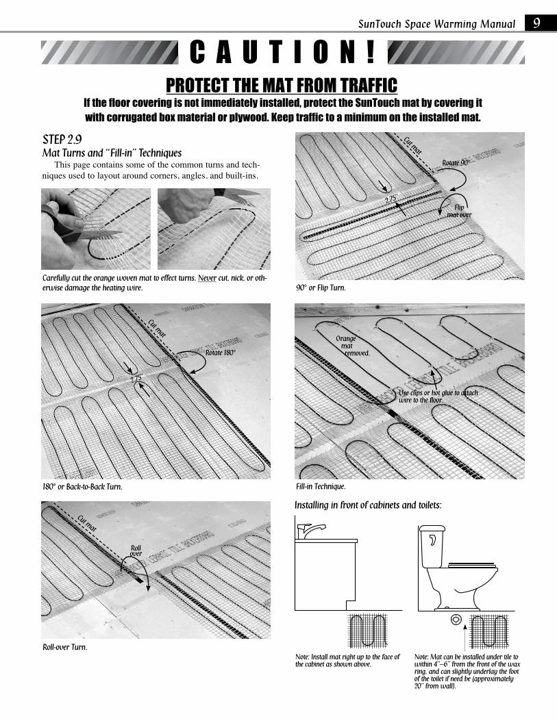
STEP 2.9 Mat Turns and “Fill-in” Techniques This page contains some of the common turns and tech-niques used to layout around corners, angles, and built-ins.
Installing in front of cabinets and toilets:
C A U T I O N !PROTeCT THe MAT fROM TRAffIC
If the floor covering is not immediately installed, protect the SunTouch mat by covering it with corrugated box material or plywood. Keep traffic to a minimum on the installed mat.
Note: Install mat right up to the face of the cabinet as shown above.
Note: Mat can be installed under tile to within 4”–6” from the front of the wax ring, and can slightly underlay the foot of the toilet if need be (approximately 20” from wall).
SunTouch Space Warming Manual 9
Fill-in Technique.
Use clips or hot glue to attach wire to the floor.
Orange mat removed.
180° or Back-to-Back Turn.
90° or Flip Turn.
Roll-over Turn.
2.75”
Carefully cut the orange woven mat to effect turns. Never cut, nick, or oth-erwise damage the heating wire.
Cut mat
Rollover
Cut mat
Rotate 90°
Flipmat over
2.75”
Cut mat
Rotate 180°
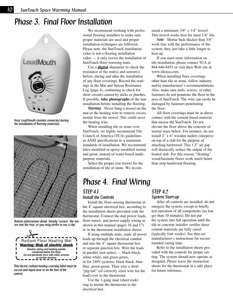
We recommend working with profes-sional flooring installers to make sure proper materials are used and proper installation techniques are followed. Please note, the SunTouch installation video is not a flooring installation video — it only covers the installation of SunTouch floor-warming mats. Use a digital ohmmeter to check the resistance of the mat(s) and sensor(s) before, during and after the installation of any floor coverings. Record the read-ings in the Mat and Sensor Resistance Log(page4),continuingtocheckforshort circuits caused by nicks or pinches. If possible, take photographs of the mat installation before installing the flooring. Warning: Never bang a trowel on the mat or the heating wire to remove excess mortar from the trowel. This could sever the heating wire. When installing tile or stone over SunTouch, we highly recommend Tile Council of America (TCA) guidelines or ANSI specifications as a minimum standards of installation. We recommend latex-modified or epoxy-modified mortar and grout, instead of water-based multi-purpose materials. Selectthepropersizetrowelforthe installation of tile or stone. We recom-
mend a minimum 3/8” x 1/4” trowel. This trowel works best for most 1/4” tile. Note: Mortar beds thicker than 3/8” work fine with the performance of the system; they just take a little longer to heat up. If you need more information on tile installation, please contact TCA at 864-646-8453 or visit their Web site at www.tileusa.com. When installing floor coverings other than tile or stone, follow industry and/or manufacturer’s recommendations. Also, make sure nails, screws, or other fasteners do not penetrate the floor in the area of SunTouch. The wire can easily be damaged by fasteners penetrating the floor. All floor coverings must be in direct contact with the cement-based material thatencasetheSunTouch.Donot elevate the floor above the concrete or mortar mass below. For instance, do not install 2” x 4” wooden nailers (sleepers) on top of a slab for the purpose of attaching hardwood. This 1.5” air gap will drastically reduce the output of the heated slab. For this reason, “floating” wood/laminate floors work much better than strip hardwood flooring.
Bottom plate/sensor detail. Simply “weave” the sen-sor into the mat, or you may prefer to use a clip.
STEP 4.1 Install the Controls Install the floor-sensing thermostat in the 4” square electrical box, according to the installation sheets provided with the thermostat. Connect the mat power leads, floor sensor, and power supply wiring as shown in this manual (pages 16 and 17) or in the thermostat installation sheets. If using multiple mats, route all power leads up through the electrical conduit and into the 4” square thermostat box or separate junction box. Wire the leads in parallel (not series) — black-black, white-white, and green-green, or for 240V systems; black-black, blue-blue, green-green. Then wire a short “pig-tail”(ofcorrectlysizedwirefortheload) over to the thermostat. Use the 1-gang mud (sheet rock) ring to mount the thermostat to the electrical box.
STEP 4.2System Start-up After all controls are installed, do not energizethesystem,excepttobriefly test operation of all components (no lon-gerthan10minutes).Donotput the system into full operation until the tile or concrete installer verifies these cement materials are fully cured (typically four weeks). See thin-set manufacturer’s instructions for recom-mended curing time. Refer to the installation sheets pro-vided with the controls for proper set-ting. The system should now operate as designed. Please leave the instruction sheets for the thermostat in a safe place for future reference.
Keep LoudMouth monitor connected during the installation of flooring materials.
10 SunTouch Space Warming Manual
Phase 3. Final Floor Installation
Phase 4. Final Wiring
This electric radiant heating warning label must be cut out and taped near or on the face of the control.
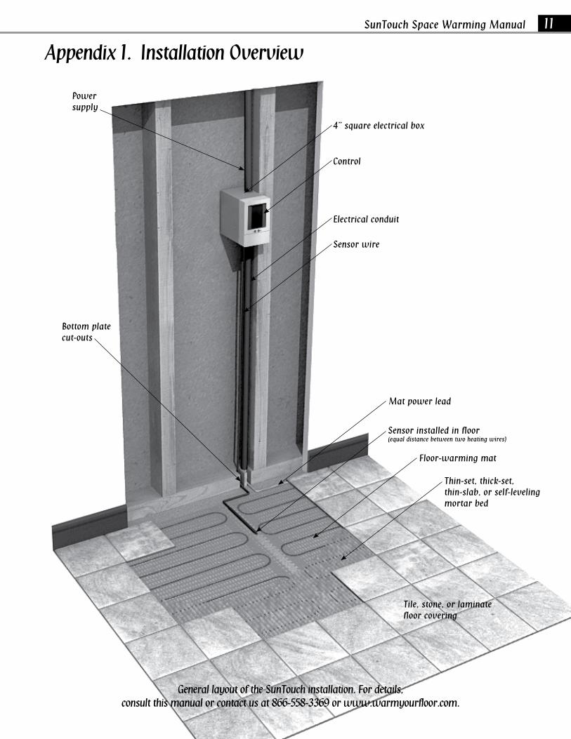
Appendix 1. Installation Overview
General layout of the SunTouch installation. For details,consult this manual or contact us at 866-558-3369 or www.warmyourfloor.com.
SunTouch Space Warming Manual 11
4” square electrical box
Bottom plate cut-outs
Power supply
Control
Electrical conduit
Sensor wire
Mat power lead
Floor-warming mat
Thin-set, thick-set, thin-slab, or self-leveling mortar bed
Tile, stone, or laminate floor covering
Sensor installed in floor(equal distance between two heating wires)

12 SunTouch Space Warming Manual
Appendix 2. Mat Turns and Fill-in Techniques
Cut
RollOver
Rotate Rotate
RotateFlip
RemoveOrange Mat
Fill Loose Wire inDesired Area
Move remaining MatUp to New Positon
Cut
Cut
Cut
90° or Flip TurnRoll-over Turn
180° or Back-to-Back Turn
Fill-in Technique
Types of turns
Step-by-step layout for a typical bathroom
1. 2. 3.
4. 5. 6.
7. 8.

Toilet
Shower
Shower
Bath Tub
Bath Tub
Closet
Bathroom layout 1: One 1’ x 40’ mat
Bathroom layout 2: One 2’ x 15’ mat, one 2’ x 60’ mat
Vanity
Vanity
Doorway
Doo
rway
Control
Control
Control
One 2’ x 15’ mat
One 2’ x 60’ mat
Toilet
Install 4”–6” from walls.
Install mats right up to the face of the cabinet. The heat only conducts about 1-1/2” from the wire.
Install mats 4”–6” away from wax ring (18”–20”) from back wall.
Fill in triangular areas by removing wire from mat and fastening with wire clips.
Do not begin the mat inside the shower area. The controls should NEVER be installed in the shower area, or where anyone in the shower could touch the controls. Install the controls a minimum of 4’ away from the shower area.
Blueheatingelement Power
leadconnection
Never install the mat in shower walls (or any other walls).
Locate power lead and connection to heating element outside the shower area.
Locate power lead and connection to heating element outside the shower area.
Refer to page 8 for full instructions for shower area installation.
SunTouch Space Warming Manual 13
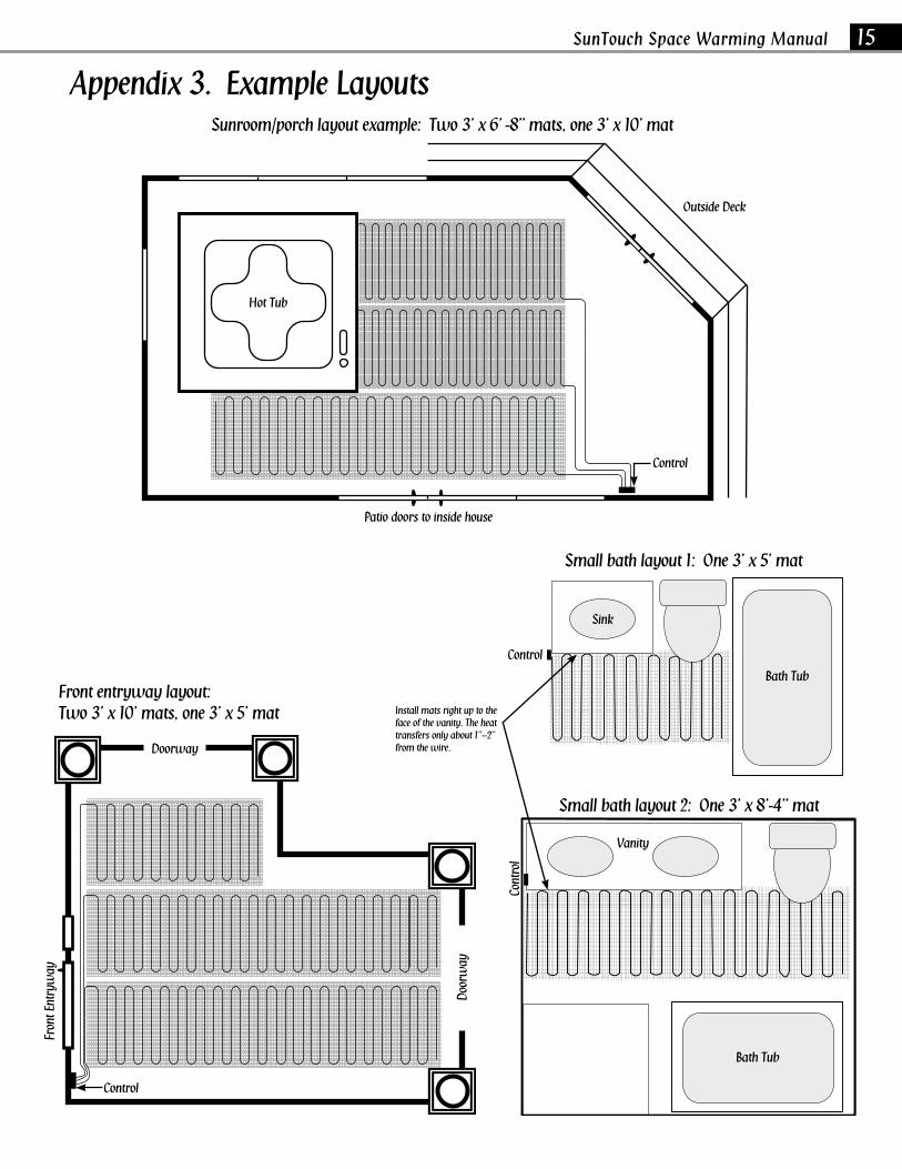
Appendix 3. Example Layouts
Toilet

Island
Washer
Refrigerator
Range
Dryer
Sink
Typical kitchen layout: One 2’ x 25’ mat, one 1’ x 35’ mat
Typical mudroom layout: Two 3’ x 10’ mats.
ControlInstall mats right up to the face of all cabinets. The heat only conducts about 1-1/2” from the wire.
14 SunTouch Space Warming Manual
Appendix 3. Example Layouts
Control
100%
Sunroom/porch layout example: Two 3’ x 6’ -8” mats, one 3’ x 10’ mat
Hot Tub
Outside Deck
Fron
t Ent
ryw
ay
Sink
Small bath layout 2: One 3’ x 8’-4” mat
Doorway
Doo
rway
Patio doors to inside house
Bath Tub
Vanity
Small bath layout 1: One 3’ x 5’ mat
Front entryway layout:Two 3’ x 10’ mats, one 3’ x 5’ mat
Cont
rol
Install mats right up to the face of the vanity. The heat transfers only about 1”–2” from the wire.
SunTouch Space Warming Manual 15
Appendix 3. Example Layouts
Control
Control
Bath Tub
Control
16 SunTouch Space Warming Manual
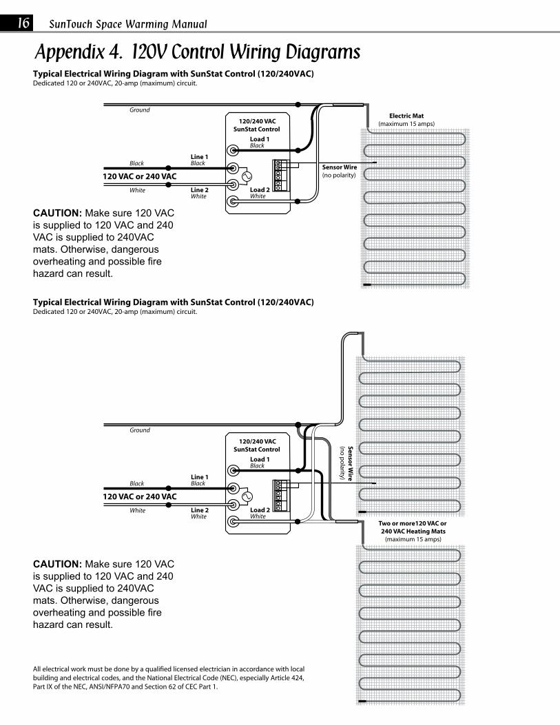
Appendix 4. 120V Control Wiring DiagramsTypical Electrical Wiring Diagram with SunStat Control (120/240VAC)Dedicated 120 or 240VAC, 20-amp (maximum) circuit.
Typical Electrical Wiring Diagram with SunStat Control (120/240VAC)Dedicated 120 or 240VAC, 20-amp (maximum) circuit.
Ground
Black Black
Black
WhiteWhite White
Line 1
Load 1
Load 2Line 2
120 VAC or 240 VACSensor Wire(no polarity)
Electric Mat(maximum 15 amps)120/240 VAC
SunStat Control
Two or more120 VAC or 240 VAC Heating Mats
(maximum 15 amps)
CAUTION: Make sure 120 VAC is supplied to 120VAC cables and 240VAC is supplied to 240VAC cables. Otherwise, dangerous overheating and possible fire hazard can result.
Ground
Black Black
Black
WhiteWhite White
Line 1
Load 1
Load 2Line 2
120 VAC or 240 VAC
Senso
r Wire
(no
po
larity)
120/240 VACSunStat Control
Ground
Black Black
Black
WhiteWhite White
Line 1
Load 1
Load 2Line 2
120 VAC or 240 VACSensor Wire(no polarity)
Electric Mat(maximum 15 amps)120/240 VAC
SunStat Control
Two or more120 VAC or 240 VAC Heating Mats
(maximum 15 amps)
CAUTION: Make sure 120 VAC is supplied to 120VAC cables and 240VAC is supplied to 240VAC cables. Otherwise, dangerous overheating and possible fire hazard can result.
Ground
Black Black
Black
WhiteWhite White
Line 1
Load 1
Load 2Line 2
120 VAC or 240 VAC
Senso
r Wire
(no
po
larity)
120/240 VACSunStat Control
All electrical work must be done by a qualified licensed electrician in accordance with local building and electrical codes, and the National Electrical Code (NEC), especially Article 424, Part IX of the NEC, ANSI/NFPA70 and Section 62 of CEC Part 1.
CAUTION: Make sure 120 VAC is supplied to 120 VAC and 240 VAC is supplied to 240VAC mats. Otherwise, dangerous overheating and possible fire hazard can result.
CAUTION: Make sure 120 VAC is supplied to 120 VAC and 240 VAC is supplied to 240VAC mats. Otherwise, dangerous overheating and possible fire hazard can result.
SunTouch Space Warming Manual 17
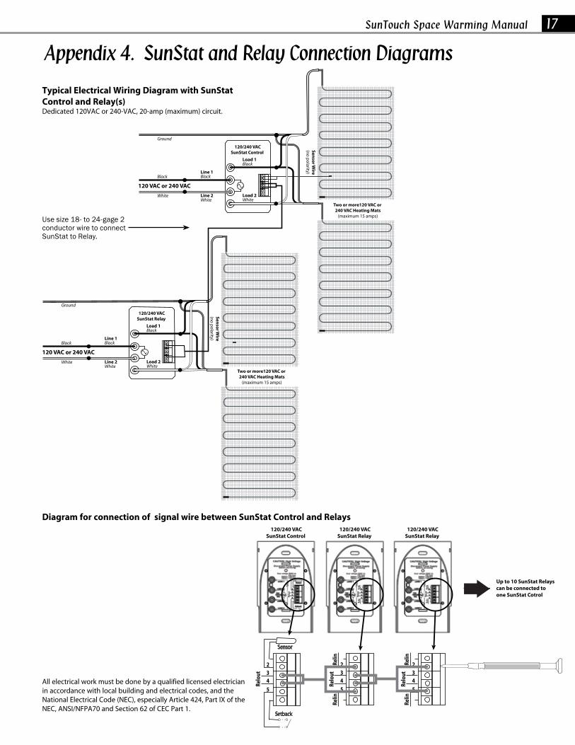
Appendix 4. SunStat and Relay Connection Diagrams
All electrical work must be done by a qualified licensed electrician in accordance with local building and electrical codes, and the National Electrical Code (NEC), especially Article 424, Part IX of the NEC, ANSI/NFPA70 and Section 62 of CEC Part 1.
Typical Electrical Wiring Diagram with SunStat Control and Relay(s) Dedicated 120VAC or 240-VAC, 20-amp (maximum) circuit.
Relout
2345
Relin
Relin
Relout
2345
Relin
Relin
Relout
Setback
Sensor
2345
Relout
Relin
Relin
Relout
Relin
Relin
Relout
120/240 VACSunStat Relay
120/240 VACSunStat Relay
Up to 10 SunStat Relays can be connected to one SunStat Cotrol
120/240 VACSunStat Control
Two or more120 VAC or 240 VAC Heating Mats
(maximum 15 amps)
Ground
Black Black
Black
WhiteWhite White
Line 1
Load 1
Load 2Line 2
120 VAC or 240 VAC
Senso
r Wire
(no
po
larity)
120/240 VACSunStat Control
Two or more120 VAC or 240 VAC Heating Mats
(maximum 15 amps)
Ground
Black Black
Black
WhiteWhite White
Line 1
Load 1
Load 2Line 2
120 VAC or 240 VACSen
sor W
ire(n
o p
olarity)
120/240 VACSunStat Relay
Relout
2345
Relin
Relin
Relout
2345
Relin
Relin
Relout
Setback
Sensor
2345
Relout
Relin
Relin
Relout
Relin
Relin
Relout
120/240 VACSunStat Relay
120/240 VACSunStat Relay
Up to 10 SunStat Relays can be connected to one SunStat Cotrol
120/240 VACSunStat Control
Two or more120 VAC or 240 VAC Heating Mats
(maximum 15 amps)
Ground
Black Black
Black
WhiteWhite White
Line 1
Load 1
Load 2Line 2
120 VAC or 240 VAC
Senso
r Wire
(no
po
larity)120/240 VAC
SunStat Control
Two or more120 VAC or 240 VAC Heating Mats
(maximum 15 amps)
Ground
Black Black
Black
WhiteWhite White
Line 1
Load 1
Load 2Line 2
120 VAC or 240 VAC
Senso
r Wire
(no
po
larity)
120/240 VACSunStat Relay
Diagram for connection of signal wire between SunStat Control and Relays
Use size 18- to 24-gage 2 conductor wire to connect SunStat to Relay.
18 SunTouch Space Warming Manual
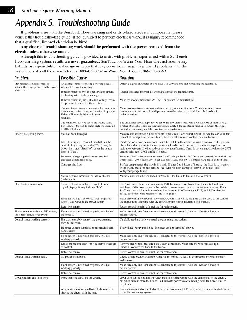
If problems arise with the SunTouch floor-warming mat or its related electrical components, please consult this troubleshooting guide. If not qualified to perform electrical work, it is highly recommended that a qualified, licensed electrician be hired. Any electrical troubleshooting work should be performed with the power removed from the circuit, unless otherwise noted. Although this troubleshooting guide is provided to assist with problems experienced with a SunTouch floor-warming system, results are never guaranteed. SunTouch or Warm Your Floor does not assume any liability or responsibility for damage or injury that may occur from using this guide. If problems with the system persist, call the manufacturer at 888-432-8932 or Warm Your Floor at 866-558-3369.
Appendix 5. Troubleshooting Guide
ProblemMat resistance measurement isoutside the range printed on the name-plate label.
Floor is not getting warm.
Floor heats continuously.
Floor temperature shows “HI” or may show temperature over 100°F.
Control is not working correctly.
Control is not working at all.
GFCIconflictsandfalse-trips
Possible CauseAn analog ohmmeter (using a moving needle) was used to take the reading.
If measurement shows an open or short circuit, the heating wire has been damaged.
If measurement is just a little low or high, room temperature has affected the resistance.
The resistance measurement could be from more than one mat wired in series, or wired in parallel. Either will provide false resistance readings.
The ohmmeter may be set to the wrong scale. Forinstance,the200Kohmsscalemeasuresupto 200,000 ohms.
Mat has been damaged.
GFCIhastripped,indicatedbyalightonthecontrol.Lightmaybelabeled“GFI”,maybebelow the words “Stand by”, or on the button labeled “Test”.
Incorrect voltage supplied, or mismatched electrical components used.
Concrete slab floor.
Mats are wired in “series” or “daisy chained” (end-to-end).
Sensor is loose or broken. If control has a digitaldisplay,itmayindicate“LO”.
Incorrect wiring. The control was “bypassed” when it was wired to the power supply.
Defectivecontrol.
Floor sensor is not wired properly, or is located incorrectly.
If a programmable control, the programming may be incorrect.
Incorrect voltage supplied, or mismatched com-ponents used.
Floor sensor is not wired properly, or is not working properly.
Looseconnection(s)onlinesideand/orloadsideof control.
Defectivecontrol.
No power is supplied.
Floor sensor is not wired properly, or is not working properly.
Defectivecontrol.
MorethanoneGFCIonthecircuit.
An electric motor or a ballasted light source is sharing the circuit with the mat.
SolutionObtain a digital ohmmeter able to read 0 to 20,000 ohms and remeasure the resistance.
Record resistance between all wires and contact the manufacturer.
Maketheroomtemperature75°–85°F,orcontactthemanufacturer.
Make sure resistance measurements are for only one mat at a time. When connecting more than one mat to the control, multiple mats must be wired in parallel (i.e., black to black, white to white).
The ohmmeter should typically be set to the 200 ohms scale, with the exception of mats having a rating above 200 ohms on their nameplate label. If the resistance reading is outside the range printed on the nameplate label, contact the manufacturer.
Measure mat resistance. Check for both “open circuit” and “short circuit” as detailed earlier in this manual. If damaged, record resistances between all wires and contact the manufacturer.
Checkforloosewireconnections.ResettheGFCIonthecontrolorcircuitbreaker.Ifittripsagain,check for a short circuit in the mat as detailed earlier in this manual. If mat is damaged, record resistancebetweenallwiresandcontactthemanufacturer.Ifmatisnotdamaged,replacetheGFCIcontrol.Alsosee“GFCIconflicts”below.
Measure “line” voltage, then measure “load” voltage. Both 120-V mats and controls have black and white leads. 240-V mats have black and blue leads, and 240-V controls have black and red leads.
Surface temperatures rise slowly in a slab. If, after 5 to 8 hours of heating, the floor is not warmer to the touch, check for mat damage (see “Mat has been damaged” above). Measure “load” voltage/amperage to mat.
Multiple mats must be connected in “parallel” (or black-to-black, white-to-white).
SunTouch controls have a floor sensor. Pull the sensor wires loose from the control and rein-sert them. If this does not solve the problem, measure resistance across the sensor wires. For a SunTouch control the resistance should be between 17,000 ohms (at 55°F) and 8,000 ohms (at 85°F). See sensor wire resistance values on page 4.
Make sure wiring connections are correct. Consult the wiring diagram on the back of the control, the instructions that came with the control, or the wiring diagram in this manual.
Return control to point of purchase for replacement.
Make sure only one floor sensor is connected to the control. Also see “Sensor is loose or broken” above.
Carefully read and follow control programming instructions.
Test voltage, verify parts. See “Incorrect voltage supplied” above.
Make sure only one floor sensor is connected to the control. Also see “Sensor is loose or broken” above.
Remove and reinstall the wire nuts at each connection. Make sure the wire nuts are tight. Check all connections back to the breaker.
Return control to point of purchase for replacement.
Check circuit breaker. Measure voltage at the control. Check all connections between breaker and control.
Make sure only one floor sensor is connected to the control. Also see “Sensor is loose or broken” above.
Return control to point of purchase for replacement. GFCIunitswillsometimestripwhenthereisnothingwrongwiththeequipmentonthecircuit, butwhenthereismorethanoneGFCI.ReroutepowertoavoidhavingmorethanoneGFCIon the circuit.
ElectricmotorsandotherelectricaldevicescancauseaGFCItofalse-trip.Runadedicatedcircuit to the floor-warming system.

SunTouch Space Warming Manual 19
Appendix 6. Connecting Multiple MatsNOTE: The thermostatic control is not shown in these diagrams in order to simplify them. These diagrams are given only as examples of how to properly connect multiple mats. Care mustbetakennottooverfillabox.Besuretousewirenutsthatarethecorrectsizefortheconnections being made. Follow all codes for wiring. If in doubt, consult an electrician.
Illustration showing how to connect three mats at the thermostatic control electrical box.
Illustration showing how to connect multiple mats from multiple junction boxes at one thermostatic control electrical box.

Mat layout grid — use this to draw a scaled layout of your room
Copyright © 2008 Watts Radiant, Inc. SunTouch Space Warming Manual WYFSPCMAN0108 Effective: 01/09/2008
SunTouch products are patented under foreign and U.S. patents including numbers 6,303,905, 6,300,598, and 5,908,573. Trademarks and U.S. Registered Trademarks and copyrighted material herein are the property of Watts Radiant, Inc.
23151 Alcalde Drive Suite B-1
Laguna Hills CA 92653-1734
1-866-558-3369 (USA & Canada)
1-866-558-2010 (Fax)
w w w . w a r m y o u r f l o o r . c o m

Electric Floor-warming Products
25-year Limited Warranty
Watts Radiant (the Company) warrants its electric floor-warming mats and cables (the Product) to be free from defects in materials and workmanship for twenty-five (25) years from the date of manufacture. Thermostats and controls sold by Watts Radiant are warranted, parts and materials, for one (1) year from the date of purchase. The sole remedy for controls is product replacement. This warranty is transferable to subsequent owners.
Under this Limited Warranty, Watts Radiant will provide the following: If the Product is determined by Watts Radiant to be defective in materials and workmanship, and has not been damaged as a result of
abuse, misapplication or modification, the Company will refund all or part of the manufacturer’s published list price of the Product at the time of purchase in accordance with the following: 100% for the first ten (10) years, then prorated on a diminishing 25-year scale for the remaining warranty period.
For example: (1) Product found defective in the 5th year will receive the full manufacturer’s published list price of the Product at the time of purchase; (2) Product found defective in the 15th year will receive 15/25ths of the manufacturer’s published list price of the Product at the time of
purchase. In order to make a claim, you must: (a) Provide the Company with sufficient details relating to the nature of the defect, the installation, the history of operation, and any
repairs that may have been made. (b) At the Company’s discretion and at the owner’s expense, ship the Product to the Company or the Company’s local representative or
distributor. (c) Provide proof that the Product was installed in accordance with the applicable Product Installation Manual and any special written
design or installation guidelines by Watts Radiant for this project. (d) Provide proof that the Product was installed in accordance with the National Electrical Code (NEC) or the Canadian Electrical Code (CEC),
and all applicable local building and electrical codes. (e) Provide a retail sales receipt or proof of purchase. The following are not covered by this Limited Warranty: (a) Any incidental or consequential damage, including inconvenience, loss of time or loss of income. (b) Any labor or materials required to repair or replace the Product or control, not authorized in writing by the Company. (c) Any labor or materials required to remove, repair or replace flooring materials. (d) Any freight or delivery costs related to the Product, the control, or any related flooring or electrical products. Watts Radiant assumes no responsibility under this warranty for any damage to the Product caused by any trades people, visitors on the job
site, or damage caused as a result of post-installation work. The staff at Watts Radiant is available to answer any questions regarding the proper installation or application of the Product at this toll-free phone number: 888-432-8932. If you are ever in doubt about the correct installation procedure to follow, or if the Product appears to be damaged, you must call us before proceeding with the installation, or proposed repair.
WATTS RADIANT DISCLAIMS ANY WARRANTY NOT PROVIDED HEREIN, INCLUDING ANY IMPLIED WARRANTY OF MERCHANTABILITY OR IMPLIED WARRANTY OF FITNESS FOR A PARTICULAR PURPOSE. WATTS RADIANT FURTHER DISCLAIMS ANY RESPONSIBILITY FOR SPECIAL, INDIRECT, SECONDARY, INCIDENTAL, OR CONSEQUENTIAL DAMAGES ARISING FROM OWNERSHIP OR USE OF THIS PRODUCT, INCLUDING INCONVENIENCE OR LOSS OF USE. THERE ARE NO WARRANTIES WHICH EXTEND BEYOND THE FACE OF THIS DOCUMENT. NO AGENT OR REPRESENTATIVE OF WATTS RADIANT HAS ANY AUTHORITY TO EXTEND OR MODIFY THIS WARRANTY UNLESS SUCH EXTENSION OR MODIFI- CATION IS MADE IN WRITING BY A CORPORATE OFFICER.
DUE TO DIFFERENCES IN BUILDING AND FLOOR INSULATION, CLIMATE, AND FLOOR COVERINGS, WATTS RADIANT MAKES NO REPRESENTA- TION THAT THE FLOOR TEMPERATURE WILL ACHIEVE ANY PARTICULAR TEMPERATURE, OR TEMPERATURE RISE. UL® STANDARD LISTING REQUIREMENTS LIMIT THE HEAT OUTPUT OF REGULAR MATS TO 12 WATTS PER SQUARE FOOT, CABLES TO 15 WATTS PER SQUARE FOOT DEPENDING ON CABLE INSTALL SPACING, AND UNDERFLOOR MATS TO 10 WATTS PER SQUARE FOOT, AND AS SUCH, USERS MAY OR MAY NOT BE SATISFIED WITH THE FLOOR WARMTH THAT IS PRODUCED. WATTS RADIANT DOES WARRANT THAT ALL PRODUCTS WILL PRODUCE THE RATED OUTPUT LISTED ON THE PRODUCT NAMEPLATE, WHEN OPERATED AT THE RATED VOLTAGE.
Some states do not allow the exclusion or limitation of incidental or consequential damages and some states do not allow limitations on how long implied warranties may last. Therefore, the above limitations or exclusions may not apply to you. This warranty gives you specific legal rights and you may also have other rights, which vary from state to state.
Terms and Conditions Shipping Discrepancies: Incoming materials should be inventoried for completeness and for possible shipping damage. Any visible
damages or shortages must be noted prior to accepting the material. Once the receiving personnel accept the material on their dock, they have relieved the freight company of any responsibility. Any discrepancy concerning type or quantity of material shipped, must be brought to the attention of Watts Radiant within 15 days of the shipping date entered on the packing slip for the order.
Return Policy: All Watts Radiant items may be returned, if they are not damaged or used. There may be a restocking charge applied to items returned due to overstock or customer order error. All returned items must be in new condition. Products, controls or other parts that have a quality defect will be replaced (not credited) at no charge to the customer. If an item is shipped in error, there will be no restocking charge. All items returned, for replacement, credit or repair, must have a Returned Goods Authorization (RGA) number, or they will not be accepted. Please call our order desk for an RGA number. Products older than 100 days are excluded from these terms and conditions and may not be returned to Warm Your Floor.
Products that have been damaged, or Products that have been cut, may not be returned. This includes Products that have had mortar or concrete materials applied to them. These Products cannot be repaired and cannot be resold; therefore, we cannot accept them.
Effective: APRIL 1, 2006. This warranty applies to all Products purchased after this date.
All products are warranteed by the manufacturer: Watts Radiant, Inc., 4500 E. Progress Place, Springfield, MO 65803-8816
Distributed by: Warm Your Floor, 23151 Alcalde Dr., Ste B-1, Laguna Hills, CA 92653 www.WarmYourFloor.com
Toll-Free Phone 866 – 558 – 3369 Toll-Free Fax 866-558-2010 [email protected]
Copyright © 2006 Watts Radiant, Inc. Electric Warranty ELECWTY0401 Effective 04/01/2006

If you worry about EMFfrom your warm floor...
...then put your baby on SunTouch
An emerging issue in the electric radiant heat industry is EMF (electromagnetic frequency) radiation. Many companies sell only single-wire
systems that release very high levels of EMF. SunTouch only sells dual wire systems, a
patented EMF-canceling technology.
Electromagnetic fields (EMF) come from all electrical appliances, but studies show
an average American's daily exposure is less than 1 unit (mG) of EMF. When you sit
on an unshielded electric radiant floor, you may be exposed to more than 40 times the average daily exposure. Shockingly, some electric floor products expose
homeowners to about the same electromagnetic field radiation as if you put your face directly against the door of a microwave oven.
Know your exposureToday, there is only one scientific and independent third party test to measure electromagnetic fields produced by electric radiant floor heating systems, known as "REET" or Radiant Electric Emissions
Test. Watts Radiant and the ETL Semko division of Intertek, the global leader in the testing, inspection, and certification of
products for manufacturers, developed REET. Unlike unverifiable claims made by some companies, the REET test measures each company’s
products according to standard procedures.
1-866-558-3369 • WarmYourFloor.com

REET Test Procedures
The difference is in the wire
The REET test procedures specify twenty standard points of measurement across a four foot by four foot area of warm tile. Unlike some companies that measure EMF 2′ or 3′ above the floor, ETL makes each measurement at an exact height of 1/2" above the electric heating wire. Those point measurements are calculated to yield an average radiation value for each product for both electric and magnetic field radiation. Calibrated, laboratory grade test equipment is defined in the REET procedures and used by ETL Semco technicians to conduct these tests. Health care concerns have focused on the magnetic, or H-field, measured in milligaus or mG.
The first series of test results for Watts Radiant products and for other manufacturers showed a startling variation in H-field exposure. In one notable head-to-head comparison of electric mats of similar size and amp rating, a competitive product emitted 462 times the H-field radiation as the Watts Radiant mat.
If you are concerned about EMF exposure, insist that any electrical floor warming products be tested by ETL Semko, and that the true EMF output, according to the REET test, be published and made available to you.
1x 10x 20x 30x 40x 50x 60x 70x 80x 90x 100xaverage U.S. exposure
Watts SunTouch: 0.05xWatts SunTouch: 0.05x
Product A: 42.38x
Product B: 45.74x
Product C: 71.34x
Product D: 92.54x
23151 Alcalde Dr Suite B-1 Laguna Hills, CA 92653-1419 www.WarmYourFloor.com866 - 558 - 3369 949 – 855 - 3369 866 - 558 – 2010 (Fax)
Copyright © 2007 Watts Radiant, Inc. SunTouch EMF Pamphlet STEMFPAM-WYF-0707 Effective 07/06/2007
SunTouch products are patented under foreign and U.S. patents including numbers 6,303,905, 6,300,598, and 5,908,573. Trademarks and U.S. Registered Trademarks and copyrighted material herein are the property of Watts Radiant, Inc. SunTouch is a division of Watts Radiant Inc. Watts Radiant, Inc. is a subsidiary of Watts Water Technologies, Inc.