space station structures and dynamics test … · space station structures and dynamics test...
TRANSCRIPT
NASA Technical Paper 2710
1987
National Aeronautics and Space Administration
Scientific and Technical Information Branch
Space Station Structures and Dynamics Test Program
Carleton J. Moore, John S. Townsend, and Edward W. hey George C. Marshall Space Flight Center Marshall Space Flight Center, Alabama
https://ntrs.nasa.gov/search.jsp?R=19870011135 2018-07-30T03:07:50+00:00Z
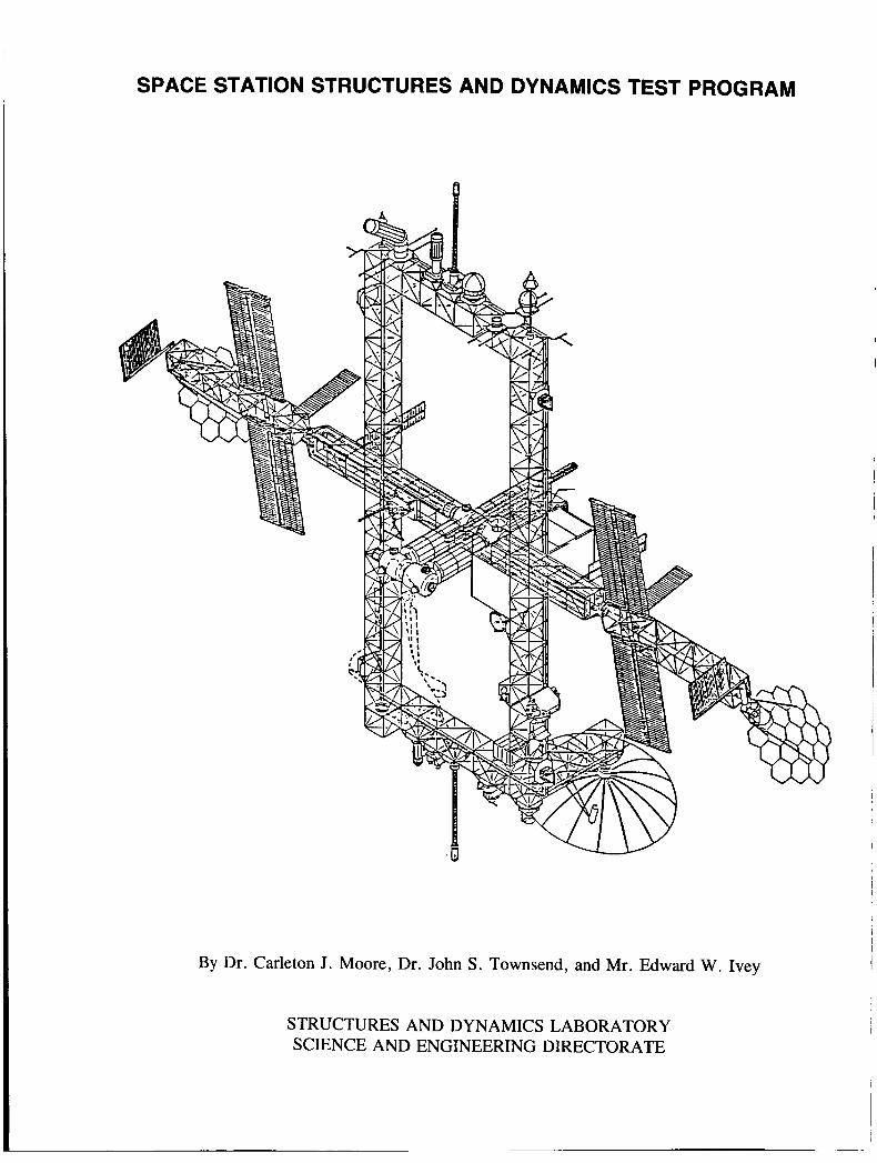
SPACE STATION STRUCTURES AND DYNAMICS TEST PROGRAM
A
By Dr. Carleton J . Moore, Dr. John S. Townsend, and Mr. Edward W. Ivey
STRUCTURES AND DYNAMICS LABORATORY SCIENCE AND ENGINEERING DIRECTORATE
TABLE OF CONTENTS
INTRODUCTION ..............................................................................................
TEST BEDOBJECTIVES .....................................................................................
Phase I Test Bed Objectives ........................................................................... Phase I1 Test Bed Objectives ..........................................................................
BACKGROUND ...............................................................................................
PROPOSEDTESTPLAN .....................................................................................
Phase I ................................................................................................... 1 . Experimental Testing of Existing Hardware ........................................... 2 . Investigation of System Phenomena .................................................... 3 . Development of Testing Techniques and Data Acquisition System ................. 4 . Model Testing of System Configurations .............................................. 5 . Passive and Active Damping Modal Control ........................................... 6 . Detailed Zero-g Simulation ..............................................................
Phase I1 .................................................................................................. 1 . Testing of Prototype Components and Subassemblies ................................ 2 . Controls and Structural Dynamic Interaction Tests ...................................
4 . Zero-G Suspension Simulation .......................................................... 3 . Ground Testing of On-orbit Test Procedures and Equipment ........................
5 . Update Prototype to Flight Configuration .............................................. 6 . Testing of Changes and Additions to Orbiting Space Station ........................
SUPPORTFACILITY .........................................................................................
Page
1
2
2 2
3
10
10 10 12 18 20 20 22 22 22 26 27 27 28 28
28
... I
iii
LIST OF ILLUSTRATIONS
Figure
1 .
2 .
3 .
4 .
5 .
6 .
7 .
8 .
9 .
10 .
11 .
12 .
13 .
14 .
15 .
16 .
17 .
18 .
19 .
Title
Suspended 50-ft SASP deployable truss ..........................................................
30.in . -diametger 20-ft-long astromast ............................................................
Space Shuttle vertical ground vibration test preparation ........................................
Space Shuttle mated vertical ground vibration test ...............................................
Vertical ground vibration test ......................................................................
SSME engine modal survey test ....................................................................
Phase I proposed test plan ...........................................................................
Characteristics of nonnlinear stiffness and response .............................................
Stiffness of fixed versus pinned connections .....................................................
Interface connections between truss elements ....................................................
Vibration decay ......................................................................................
Standing wave testing ...............................................................................
Diagram of remote optical test scheme ............................................................
Air support with inverted air bearing and jig support ............................................
A typical deployable space truss joint connection ................................................
Joint stiffness parameters under low preload stiffness of joint for 1 -in . diameter steel ball on flat steel plate .....................................................
Phase I1 proposed test plan ..........................................................................
Flat floor facility, Space Station dynamic test ....................................................
Planar Zero-frequency Orbital Simulator (PLAZOS) ...........................................
Page
4
5
6
7
8
9
11
14
15
15
17
17
19
21
23
24
25
27
29
LIST OF ILLUSTRATIONS (Concluded)
Figure
20 .
21 .
22 .
23 .
24 .
25 .
26 .
27 .
28 .
Title
Cable support and negative spring mechanism ...................................................
Hybrid cable and air bearing suspension system .................................................
Neutral Buoyancy Simulator complex ............................................................
Truss assembly in Neutral Buoyancy Facility ....................................................
44 X 86-ft air bearing epoxy resin floor ...........................................................
MSFC test facilities ..................................................................................
Space Station mechanism development ...........................................................
6-DOF motion simulator ............................................................................
Intergraph color graphics work station ............................................................
Page
30
30
31
32
33
35
37
38
40
...

TECHNICAL PAPER
SPACE STATION STRUCTURES AND DYNAMICS TEST PROGRAM
INTRODUCTION
The Space Station presents a unique opportunity to build a structure constructed for a weightless environment. It is true other structures were designed to function in a weightless environment, but unlike the Space Station, these structures were also designed to be assembled on the Earth’s surface and then to withstand the gravity (8) loads associated with launch. The stringent requirements of the static load environment have, for a large part, played the major role in the design of past structures. The Space Station structures will depart from this past precedent in that dynamics will now play a major role in structural design. It will be important in the initial design phase to define the parameters and phenomena affecting system dynamics.
The unique zero-g construction and operation environment of the Space Station will require an additional dependence on analytical techniques. Ground-based testing has in the past been very important in verifying analytical models and determining key parametric data during the initial design phase and finally the actual flight hardware after it is constructed. The Space Station can never be ground tested in the fully assembled configuration. Thus, analytical analysis will play a major role in the design of the Space Station. Special emphasis will be placed on math model correlation and verification and development of parametric data base applicable to design using full-scale components and scale models.
The development of this test data base will require an indepth investigation of phenomena affecting the dynamics of the Space Station along with engineering methods of enhancing the dynamic architecture. The test investigation of phenomena will evaluate materials, joint connections, and construction tech- niques with regard to damping and stiffness variation with displacement. The enhancement of the dynamic architecture requires investigation of passive and active damping, passive and active isolation, and interac- tive control system architecture. The low modal frequencies of the Space Station are going to interact with those of the control systems necessary for positioning of solar arrays, antennas, telescopes, and tracking devices. Thus, it is necessary to develop and test interactive control systems which can enhance the struc- tural design and not be a detriment.
The test proposal, as outlined in this document, is a comprehensive structural dynamics program to be launched at MSFC in support of the Space Station. The philosophy being to integrate dynamics into the design phase through extensive ground testing and analytical ground simulations of generic systems, proto- type elements, and subassemblies. MSFC has the test facilities, analytical tools, expertise, and technology, as can be seen from past history, to successfully perfon the necessq- Space Station dynamic tests. The unique organizational structure, structural dynamics and controls in the same organization at MSFC, along with major test facilities and experience provide a team that should greatly enhance this test bed. The experience, organization, and facilities are ready for focusing on the individual job tasks as they evolve.

The design and development of a low-Earth orbit Space Station poses unique challenges for development and implementation of new technology. The technology arises from the special requirement that the station be built and constructed to function in a weightless environment, where static loads are minimal and secondary to system dynamics and control problems. Specific challenges confronting NASA are:
1 . Develop a general test program for defining Space Station design requirements.
2. Develop the analytical tools and techniques necessary for supporting the Space Station design efforts.
3. Identify and characterize phenomena affecting Space Station design and development.
The tests needed to address the structural dynamic needs are presented in the following sections. MSFC has the test facilities, analytical tools, expertise, and technology to successfully perform the neces- sary Space Station dynamic tests.
The Space Station proposed tests will be conducted in-house using predominantly the test facilities of MSFC with support of other NASA Centers. The experience, expertise, technology, and capability for performing structural dynamic tests and analyses have been acquired from the many and varied tests con- ducted here by NASA from the Saturn I to the present testing of large space structures. Figures 1 and 2 depict the SASP 50-ft deployable truss and the 304n.-diameter, 20-ft-long ASTRO mast which are presently being tested.
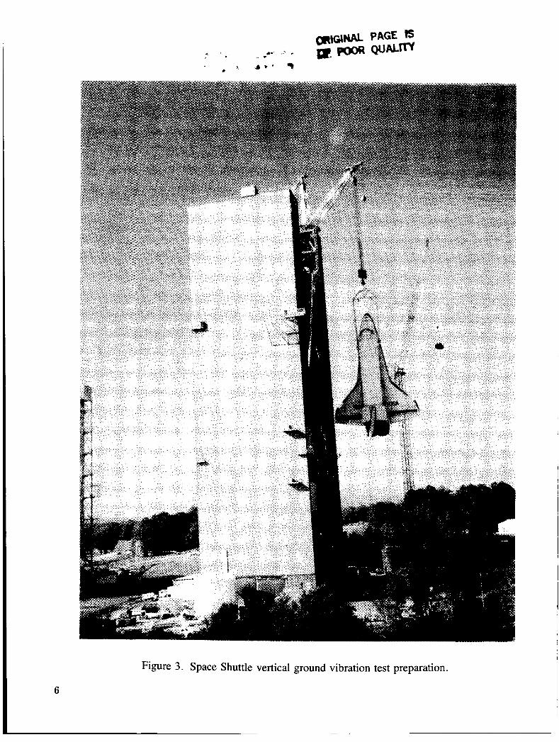
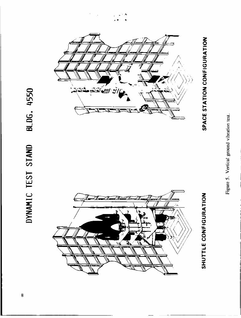
The largest dynamic test performed by NASA at MSFC was the Space Shuttle Mated Vertical Ground Vibration Test (MVGVT) shown in Figures 3 and 4. An artist's rendition of a portion of the Space Station housed in test building 4550 is shown in Figure 5. This test provided an experimental data base in the form of structural dynamic characteristics and was used in developing a high confidence in the analyti- cal models for the prediction and design of loads, pogo, controls, and flutter.
A typical example of component testing is the refurbished Space Shuttle Main Engine (SSME) nozzle assembly as shown in Figure 6 . This test was initiated to determine the cause of the SSME nozzle steerhorn failure. A modal survey test using the single-point random technique and roving accelerometer was used to map the many nozzle modes and the local downcomer/steerhorn modes. From the modal tests, two modes were identified which created severe structural problems. As a result of these tests, design changes were made to eliminate future steerhorn failures.
MSFC has proven indepth analytical analysis capability of structural dynamic systems. Some of the proven analysis tools are NASTRAN, SPAR, and FORMA. This analysis capability is currently being extended with the acquisition of a Class 6 computer and several Intergraph interactive graphics wark stations, microcomputers, frequency analyzers, and hybrid computers. Other NASA Centers, such as Langley and JSC, have complementary capability.
3

Figure 1 . Suspended 50-ft SASP deployable truss.
4

TEST BED OBJECTIVES
The Space Station ground dynamic test program and its objectives have been divided into two test phases. Objectives in the first phase emphasize the verification of math models and the development of a parametric data base. Phase I testing will use existing generic hardware and model testing. These tests can begin immediately and will help define the key issues and problems that will be associated with the Space Station. Objectives in the second phase will emphasize verification of the math models and developmental support of the Space Station’s design evolution. Phase I1 testing will use generic and prototype hardware. The primary objectives for the structural dynamic test bed for Phases I and I1 are as follows:
Phase I Test Bed Objectives
1.
2.
3.
4.
5 .
6 .
7 .
8 .
1.
2.
3.
4.
5 .
6 .
2
Develop and verify the math models and analytical analysis tools necessary for engineering support of the Space Station design, construction, and operation.
Develop a parametric data base necessary for defining criteria for the Space Station configuration optimization.
Identification and characterization of unknown phenomena.
Investigate passive and active damping control concepts along with interactive control systems.
Investigate behavior or joint properties under very low preloads to determine the effects of zero-g.
Investigate ground test measurement systems and data reduction techniques for low frequency large amplitude vibrations.
Develop more efficient and less time consuming methods of testing and data acquisition for large Space Station structures.
Develop on the ground the equipment and techniques necessary for on-orbit testing.
Phase II Test Bed Objectives
Determine structural dynamic characteristics for structural math model verification and for use as a parametric data base from tests of both generic and prototype components and assemblies.
Provide dynamic simulation of docking and reboost and other events.
Provide engineering developmental support and verification of passive and active damping, passive and active isolation, and interactive control system architecture.
Perform verification ground tests on developmental and prototype flight hardware.
Development of approaches and testing techniques and equipment for on-orbit structural dynamic test- ing.
Update prototype to flight configuration to allow continued capability to provide ground test support for on-orbit Space Station hardware.
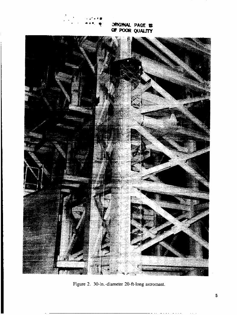
Figure 2. 30-in. -diameter 20-ft-long astromast .
5
_-
Figure 3. Space Shuttle vertical ground vibration test preparation.
6

ORIGINAL PAGE TS OF POOR QUALITY
Figure 4. Space Shuttle mated vertical ground vibration test.
7
i ,?
c U 3 (3
a - LL 2 0 0
- c U c v)
W 0 U Q v)
Y rn s
t v,
V
r: U z )., 0
W
U 3 (3
2 0 0
a - LL
W
c c 3 I v)
2 0 c -
8

Figure 6. SSME engine modal survey test.
9
- *
It is realized that the Space Station abfi&dGes with their complexity of high modal density, low frequency, nonlinearity, and unsymmetrical coupling will offer a challenge to test. However, the test facili- ties, analytical tools, expertise, and technology, as can be seen from past history, are available to success- fully perform the necessary Space Station dynamic tests.
PROPOSED TEST PLAN
Phase I
1. Experimental Testing of Existing Hardware
The initial phase of the ground test program will emphasize experimental testing of existing hardware as presented in Figure 7. Along with this testing, math models and analytical techniques will be developed for application to the Space Station design phase. The existing analytical tools which will be applied are NASTRAN, SPAR, and FORMA. Also, there will be large scale use of Intergraph work stations for finite element modeling and display of analysis results. The use of this interactive color graphics system will increase the engineer’s productivity and allow effective visual communication of the analysis results.
The primary goals are the verification of analytical models, development of a parametric data base, evaluation of test procedures and techniques, and development of new test articles and technology. The impetus of the program will be to define key issues and/or problems inherent to large space structure analysis and design.
Although the Space Station configuration remains undefined, the main structural building block is known in the generic sense as a truss element. Currently, the 30-in.-diameter, 20-ft-long ASTRO mast and the 50-ft SASP deployable trusses are available at MSFC and have been partially tested. Photographs of the trusses are given in Figures 1 and 2. A 50-ft ASTRO mast arrived at MSFC in the summer of 1984. Also, the I-m beam truss (16-m length) designed for on-orbit fabrication is an in-house item. Deployable trusses are the more attractive of the two design concepts. Characteristics common to these structural elements include ( 1) multi-joints/load paths, (2) low frequency/high modal density, and (3) large deflections/ nonlinear behavior. These prototype structural elements and the following proposed tests will provide benchmarks on which to base future development.
Of major concern are the nonlinear effects excited by the dynamic and structural action of the con- necting joints. Preliminary test results show joint damping to be nonlinear and structural stiffness to vary with displacement. These and related problems must be addressed before accurate math models of the components can be formulated. The basic tests proposed include ( 1 ) modal testing to determine state identi- fication of the structure at low frequency, small amplitude oscillation and (2) large amplitude vibration to establish the time varying nature of the structure. Details of these tests are discussed below.
a. Modal Testing
Sine wave sweep testing and single-point random excitation are the two techniques presently employed by the space industry to drive out the modal characteristics and state identification of a structure.
10

a
a 8 i2
11
The impulse technique (random excitation) is ill-suited for frequency response testing of nonlinear struc- tures. However, the method may prove acceptable for low amplitude motion and give the best estimate of the linear system response. Boundary constraints are important in defining the system modal characteris- tics; tests are proposed for the free and fixed domains. Experimental investigation will be directed toward the development of low frequency isolation technology to be used for ground test support systems and also for Space Station application.
The linear dynamic response of this test phase may be insured by preloading the connecting joints. One method proposed is the application of tension loads to the structure in incremental fashion. The tensile forces will tend to increase structural stiffness and hence natural frequency, but the low frequency mode shapes may prove independent of tension. A parametric study of this nature provides a tool for characteriz- ing system modal properties, especially damping.
b. Large Amplitude Vibration
Forced vibration using sine wave excitation at system natural frequencies will be the basic tech- nique utilized during this phase of the test program. The purpose of the large amplitude vibration will be used to investigate the nonlinear nature of the system. Similar parametric studies as outlined above are proposed. These techniques will help to pinpoint the strong nonlinearities in the structure, either of stiffness or damping origin. Static force deflection tests will be very important to help characterize the stiffness parameters. Vibration decay testing is proposed for measuring system damping properties.
2. Investigation of System Phenomena
Anticipated phenomena affecting the large Space Station structures may be classified into general categories as follows:
Composite material gassing in a vacuum.
Terminal expansion and contraction effects.
Radiation modification of material properties.
Material nonlinearities/stiffness, damping.
Joint motion/stiffness, damping.
Large displacements/geometric nonlinearity.
During Phase I testing, an indepth study will be initiated to examine system dynamics due to phenomena affecting material properties. Special attention will be given to the load sensitivity of joint stiffness and techniques for measuring and increasing joint damping. Comparative testing of standard truss con- figurations will be used to characterize the stiffness and damping parameters of various structural materials; aluminum versus glass/epoxy is one example. These types of tests will generate an experimental data base on which to correlate analytical models and evaluate materials, parameters, and design concepts.
12
a. Stiff ness Nonlinearities
Material and joint stiffness are two areas to examine. Static tests using influence coefficients to define stiffness will form the basis of this nonlinear study. The importance of static testing must not be overlooked if we are to accurately define stiffness parameters and model system response. Dynamic tests will be used to determine average stiffness values or best estimates of equivalent linear behavior.
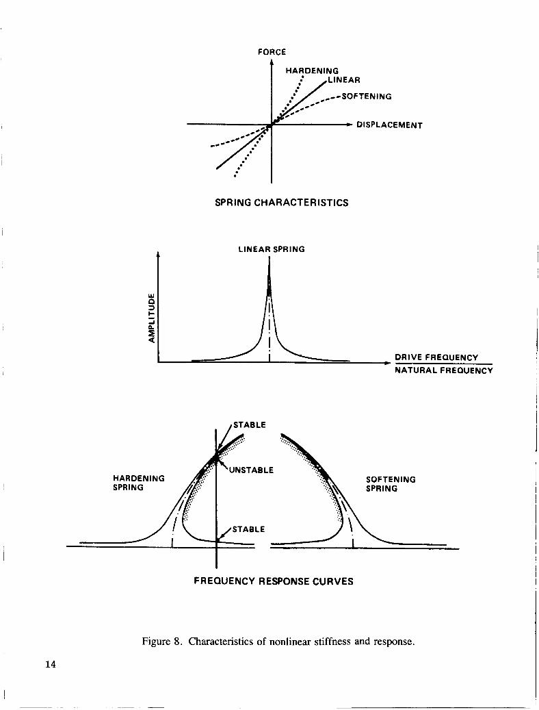
The nonlinear effects of stiffness on system response are best exemplified by an example problem given in Figure 8. The figure shows the response of a simple single degree of freedom oscillator undergoing forced harmonic motion. Two classes of nonlinear stiffness are examined (a soft and hard spring) assuming a linear damping force. These nonlinear springs are compared versus a linear spring.
The stiffness nonlinearity bends the frequency response curve away from the linear curve to the right for hard springs and to the left for soft springs. At agiven drive frequency, we get two stable solutions, which one occurs depends on initial conditions. As system damping increases, the solutions collapse to the linear case (not shown). This very simple example identifies some of the problems that complicate non- linear testing and analysis of multiple degree of freedom systems. Specifically, mode shapes and frequen- cies will change with time. The rate at which these parameters vary determines the degree of nonlinearity. If a structure is weakly nonlinear, then standard dynamic testing techniques may be sufficient. For strongly nonlinear structures, dynamic testing must be supported by static testing until new test and analysis proce- dures are verified.
Static influence coefficient testing is proposed on symmetric generic truss configurations where the joints are pinned and fixed. Since the deployable trusses are the current adopted design concept, the test objective will be to investigate pinned connections. Torsional, bending, and axial stiffness will be deter- mined. This type of test will require special rigging and load application. For a particular truss design, the load deflection diagram for the fixed pinned joint cases could resemble the curves in Figure 9. In the piece- wise linear diagram shown, the pinned case defines both the material stiffness (K) and the joint stiffness (K, ) with a single curve. We expect the difference between these stiffness (K and K 1 ) to be a function of truss material (assuming joint design is constant). The proposed test will address the relationship between K, K 1 , and K2 as a function of material and joint parameters. When possible, dynamic testing will be used to support the findings.
As the number of bays in the generic truss structure is increased, the stiffness of the assembly will decrease. The same result holds true when coupling together in series individual truss elements to form long support structures for solar arrays and antennas. The complete assembly is very flexible with structural stiffness decreasing rapidly as the span length increases (for example, the bending stiffness of a canti- levered beam decreases as the length cubed). The generic trusses will be used to study the interface stiffness connections between two similar truss elements (Fig. 10).
If the interface stiffnesses are higher than the individual truss element stiffnesses, then the interfaces will form hardpoints across the coupled system. It may be advantageous to reduce the stiffness at selected interface joints across the span. The purpose being to add damping elements (passive or absorber type) at these locations. Tests on generic trusses would provide a method of evaluating the damping units and studying stiffness-damping tradeoffs.
13
FORCE
t HARDENING
. . I SPRING CHARACTERISTICS
LINEAR SPRING
DRIVE FREQUENCY
NATURALFREQUENCY
HARDENING SOFTENING
FREQUENCY RESPONSE CURVES
Figure 8. Characteristics of nonlinear stiffness and response.
14

FORCE
JOINT FREE PLAY c - I . 'DEFLECTION
Figure 9. Stiffness of fixed versus pinned connections.
INTERFACE ELEMENT (TYP.)
Figure 10. Interface connections between truss elements.
15
b. Damping Nonlinearities
The vibrational energy of a long, flexible pin connected truss is dissipated by the combined effects of span end losses/interface motions, material friction/hysteresis action, joint friction/joint contact, and joint impact damping/joint rattling. Neglecting impact dissipation (low-g) and assuming the case of minimal end losses, primary damping actions of the vibrating truss elements result from material hysteresis and joint friction. In the strictest sense, both of these damping mechanisms are frequency independent and nonlinear. The generic and prototype truss models used in the stiffness investigation will provide the neces- sary tools to examine mechanical damping due to material, joint, and interface design. Two measurement techniques are proposed for determining the energy dissipation mechanisms in space truss systems: ( 1 ) vibration decay testing and (2) standing wave testing.
Decay testing will be the basic method used for measuring the damping properties in a beam truss, where the rate of amplitude decay is a function of system losses. Decay rate is expressed in terms of the logarithmic decrement,
6 = l/n In (YJY,)
where 6 is the logarithmic decrement, n is the number of vibrating cycles, Yo is the amplitude of time to, and Y, is amplitude n cycles after time b. Log decrements for truss systems are determined by driving the truss or span into a uniform amplitude resonance and disconnecting the shaker. The decay of vibration amplitude is then plotted against cycle time. Decay curves of linear-damped systems are exponential and become straight lines when plotted on semi-log coordinates. The log decrement value is then defined as the slope of the log amplitude - cycle count graph. The major advantage of vibration decay testing is that a large range of amplitudes can be investigated by a single test.
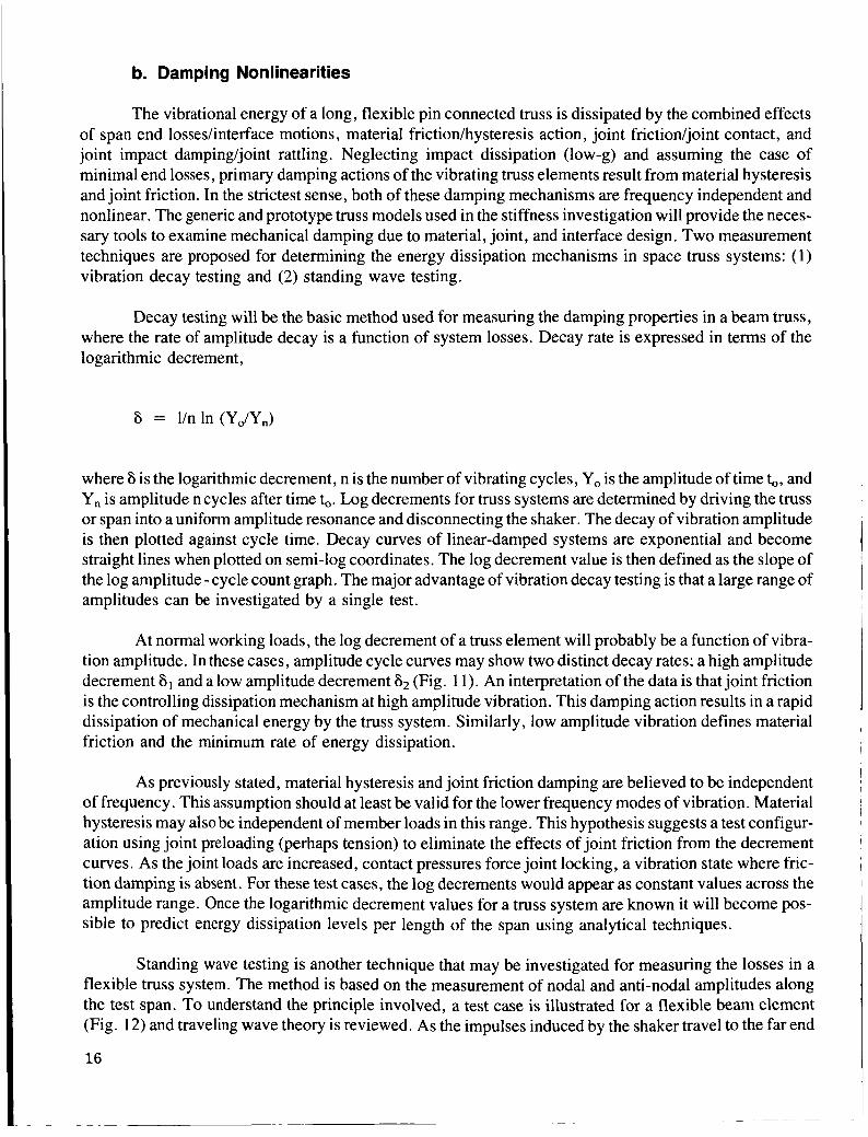
At normal working loads, the log decrement of a truss element will probably be a function of vibra- tion amplitude. In these cases, amplitude cycle curves may show two distinct decay rates; a high amplitude decrement 61 and a low amplitude decrement ti2 (Fig. 1 1 ) . An interpretation of the data is that joint friction is the controlling dissipation mechanism at high amplitude vibration. This damping action results in a rapid dissipation of mechanical energy by the truss system. Similarly, low amplitude vibration defines material friction and the minimum rate of energy dissipation.
As previously stated, material hysteresis and joint friction damping are believed to be independent of frequency. This assumption should at least be valid for the lower frequency modes of vibration. Material hysteresis may also be independent of member loads in this range. This hypothesis suggests a test configur- ation using joint preloading (perhaps tension) to eliminate the effects of joint friction from the decrement curves. As the joint loads are increased, contact pressures force joint locking, a vibration state where fric- tion damping is absent. For these test cases, the log decrements would appear as constant values across the amplitude range. Once the logarithmic decrement values for a truss system are known it will become pos- sible to predict energy dissipation levels per length of the span using analytical techniques.
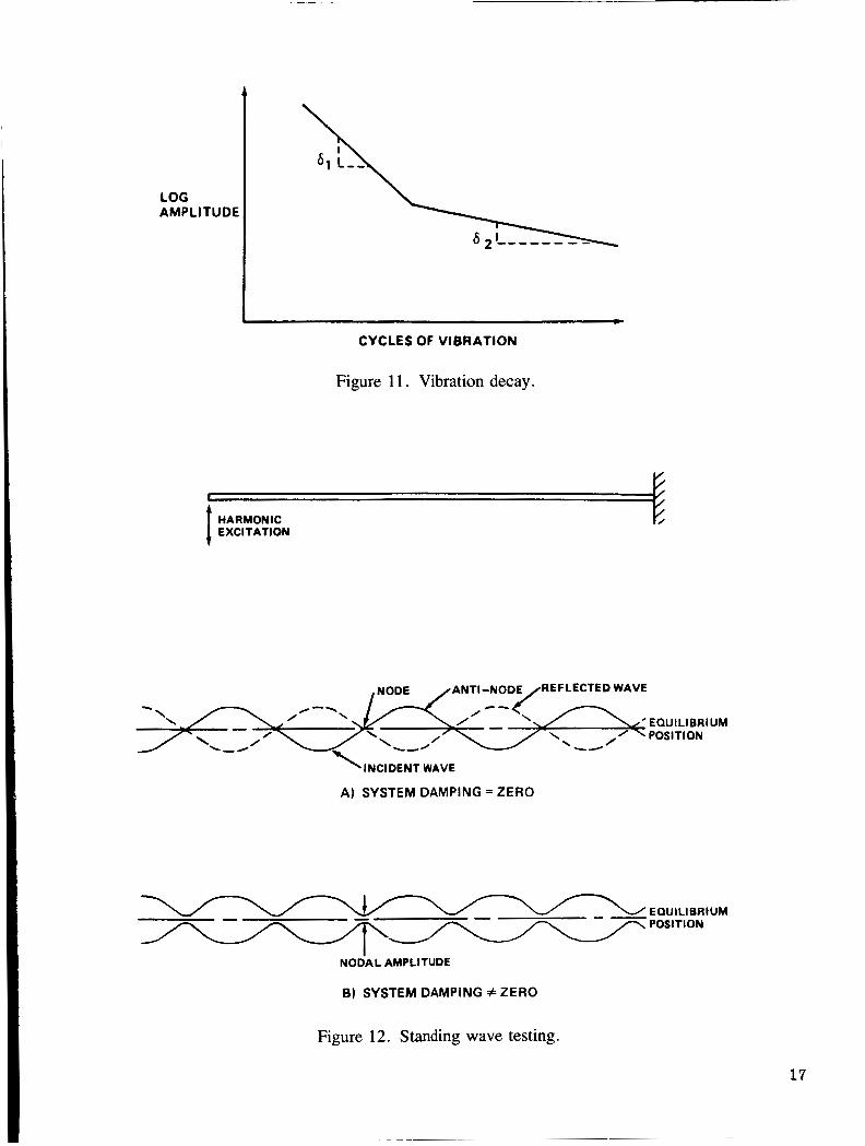
Standing wave testing is another technique that may be investigated for measuring the losses in a flexible truss system. The method is based on the measurement of nodal and anti-nodal amplitudes along the test span. To understand the principle involved, a test case is illustrated for a flexible beam element (Fig. 12) and traveling wave theory is reviewed. As the impulses induced by the shaker travel to the far end
16
CYCLES OF VIBRATION
Figure 1 1 . Vibration decay.
HARMONIC EXCl TATION
REFLECTED WAVE
EQUILIBRIUM
A) SYSTEM DAMPING = ZERO
EOUlLlBRlUM POSITION
NODAL AMPLITUDE
6) SYSTEM DAMPING #ZERO
Figure 12. Standing wave testing.
17

of the span, they return as reflected waves. If no losses are present in the system, the incident and reflected waves are equal. Perfect nodes are formed where the two waves meet and pass, i.e., the motion or dis- placement at the nodes is zero. The anti-node amplitude is equal to the sum of incident and reflected waves. If damping is present in the system, then motion at the nodes will occur. The nodal amplitude is the differ- ence between the incident and reflected waves. Energy dissipation in the system can be defined in terms of the ratio between the node and anti-node displacements. The technique has important application where energy dissipation is high.
3. Development of Testing Techniques and Data Acquisition System
The Phase I experimental ground testing will address the development of experimental dynamic testing techniques and equipment. This development has two basic goals. The first goal is to develop more efficient and less time consuming methods of testing and data acquisition for these large Space Station structures. The second goal is to develop on the ground the equipment and techniques necessary for on- orbit testing. Optical data acquisition and large space structure suspensions are two possible areas of new technology development. A discussion is given below.
a. Optical Data Acquisition
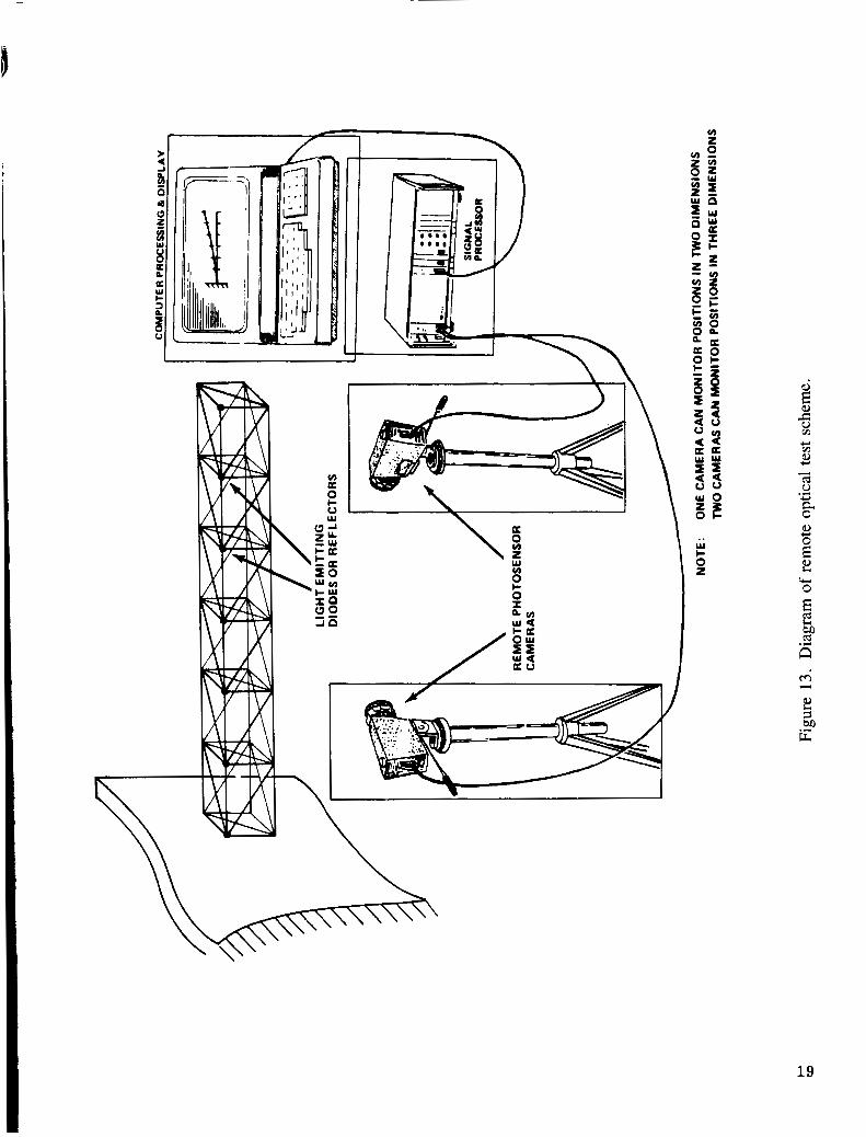
It is important in dynamic testing to define the motion of the structure when subjected to excitation. One workable technique which would be usable in orbit is the application of optical methods for determin- ing position and motion. Optical methods may also be developed which allow for more efficient computer automated data acquisition for large structures. Such optical systems have already been developed from the technology necessary for star tracking devices. A diagram of a possible optical test scheme is shown in Figure 13. One such system has been proposed for the Solar Electric Propulsion System Dynamics Experi- ment. This functioning optical system uses solid-state devices to combine dependability with light weight. This optical technique uses conventional or laser light emitting diodes. These diodes are either mounted on the structure at the position to be monitored or they are positioned to illuminate reflecting targets. A remote optical sensor coupled with a microcomputer is used to monitor the relative motions. This system has been shown to be usable even in daylight conditions. Development and application of such optical methods can allow instant acquisition of complete dynamic data on the ground or in space. This development of optical technology will also be useful for monitoring the Space Station structure during reconstruction and deploy- ment. The remote capability to accurately sense position can be important to assembly. Upon completion of the Space Station, the remote optical sensing capability could feedback to interactive control systems necessary for accurate positioning of solar cells, antennas, telescopes, and tracking devices. This feedback would allow more precise positioning under dynamic conditions introduced by the work and mission environment.
b. Large Space Structure Suspension
There is a need for development and testing of free-free suspension systems for the dynamic testing of large structures associated with the Space Station. This development is needed due to the fact that the expected flexible frequencies of the Space Station will probably be less than 1 Hz. The suspension system frequencies should be less than 1/4 of the first flexible mode. This frequency separation will ensure decoupling of the flexible modes from those of the suspension system. A comparison will be made of spring suspension versus air bearing support for large flexible structures.
18
w o % E w I- O 2
c w e, Y
* (d 0
a 0
.r( Y
& rcl 0
(d E
19
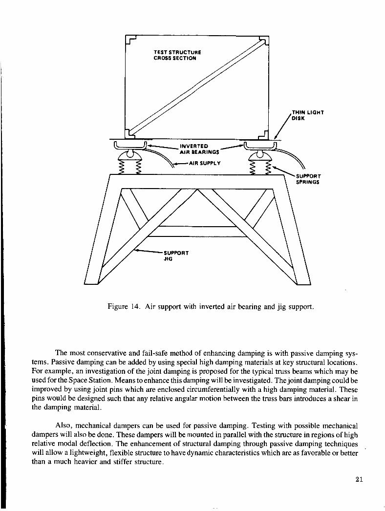
Experiments with air support can utilize the experience and facilities of the staff and equipment of the MSFC flatfloor facility. This development of air suspension experimental techniques will allow ground based dynamic simulation of construction and final working environment. By using the MSFC expertise in air support, very large structures can be dynamically tested. An interesting alternative to using the flatfloor exclusively is to utilize jacks or jigs at support positions with inverted air bearings. These air bearings will act on lightweight circular pads connected to the test structure as shown in Figure 14.
4. Model Testing of System Configurations
The structural dynamic characteristics of the Space Station must be known accurately to ensure control system stability and the capability to safely perform the desired mission requirements. The response of the Space Station must be accurately predicted when subjected to such things as control pulses, docking loads, and orbit reboost. The large size of the Space Station along with its zero-g design results in a struc- ture that can never be tested as a complete configuration in a one-g ground test environment.
The use of properly scaled dynamic models to obtain experimental data can permit an evaluation of analytical models and techniques. This testing can provide Space Station designers with valuable informa- tion on proposed configurations early in their development cycle. The degree of geometric similarity which is maintained between the dynamic model and its prototype will influence the applicability, the amount and type of information which may be obtained from model tests. A feasible Space Station scale model can be very large in size and would require the large scale test capability of MSFC.
The Space Station scale model configuration testing will be correlated with a concurrent theoretical analysis. This correlation will allow the required dependence on analytical analysis that will be necessary for the Space Station. The ability to confidently use analytical parameter studies will be valuable as the design progresses.
5. Passive and Active Damping Modal Control
Space Station appendages (radiators, solar panels, booms, antennas, etc.) will be highly flexible, lightly damped structures. Disturbances such as those arising from crew motion, berthing, equipment pointing, and Space Station reboost will excite these appendages. The resulting motion may be objec- tionable because of duration and amplitude if natural damping of the structure is relied on exclusively. Three basic approaches are available for dealing with this problem:
1 . Augmenting the damping of the structure itself with passive damping systems so that following an excitation, the motion dies out rather quickly.
2. Isolating the disturbance sources (crew module, berthing interface, etc.) from the excitable appendages. This could be passive or active isolation.
3. Actively damping the most ea'sily excitable modes in the structure using sensors and actuators in the distributed control architecture.
20
TEST STRUCTURE
I \ SPRINGS
Figure 14. Air support with inverted air bearing and jig support.
The most conservative and fail-safe method of enhancing damping is with passive damping sys- tems. Passive damping can be added by using special high damping materials at key structural locations. For example, an investigation of the joint damping is proposed for the typical truss beams which may be used for the Space Station. Means to enhance this damping will be investigated. The joint damping could be improved by using joint pins which are enclosed circumferentially with a high damping material. These pins would be designed such that any relative angular motion between the truss bars introduces a shear in the damping material.
I
I Also, mechanical dampers can be used for passive damping. Testing with possible mechanical
dampers will also be done. These dampers will be mounted in parallel with the structure in regions of high relative modal deflection. The enhancement of structural damping through passive damping techniques will allow a lightweight, flexible structure to have dynamic characteristics which are as favorable or better than a much heavier and stiffer structure.
21
The most effective damping system for quick damping of high energy dynamic motion would be active control methods. These systems can produce dramatic results for limited dynamic modes. Active damping control requires sophisticated interactive control systems which are subject to failure. These sys- tems in critical regions would require backup control systems, because it is possible that failure could impart energy into the system and amplify certain destructive dynamic modes. Active damping systems could be quite effective when used to combat infrequent mission related loads such as docking, reboost, etc. Since these systems can be scheduled and planned, the control systems could be checked for proper operation and then activated. The use of active damping control to manage infrequent high energy dynamic excitation for appendages such as the solar cells will allow the use of lightweight cost-effective structures.
The testing of all of these damping techniques must be pursued in a timely fashion to develop the low frequency damping technology which can be applied to the Space Station design. The proper damping system architecture can allow significant savings in structural weight which translates directly into signifi- cant savings in the cost of the Space Station.
6. Detailed Zero-g Simulation
One item of prime interest for large space structures is the nonlinear behavior of joints under very low preloads. Deployable trusses, the prime candidate for many early space structures, contain a multitude of such joints. A typical joint connection is shown in Figure 15. Accurate ground simulation of joint proper- ties requires that the zero preload be simulated accurately. For example, a 1-lb preload on a joint with a 1 -in. steel ball bearing on a flat plate will exhibit a stiffness near lo5 lb/in. Parametric variation is shown in Figure 16.
Most previous studies have concentrated on supporting structure section by section. This may not be adequate. Support of individual members, each by its own cable or air bearing, does not appear prac- tical. Therefore, efforts should be directed toward low-stiffness, interelement members to carry the gravity loads and unload the joints.
Desirable properties of any weight-unloading member would be:
1 . Low stiffness.
2. Low mass.
3. Accurate force control.
4. Easy installation.
Phase II
1. Testing of Prototype Components and Subassemblies
The tests proposed for Phase I1 of the ground test program are natural extensions of the technology and techniques developed in Phase I. The proposed test plan is given in Figure 17. The purpose of Phase 11 testing is to verify math models of the Space Station prototype components and subassemblies. In many
22
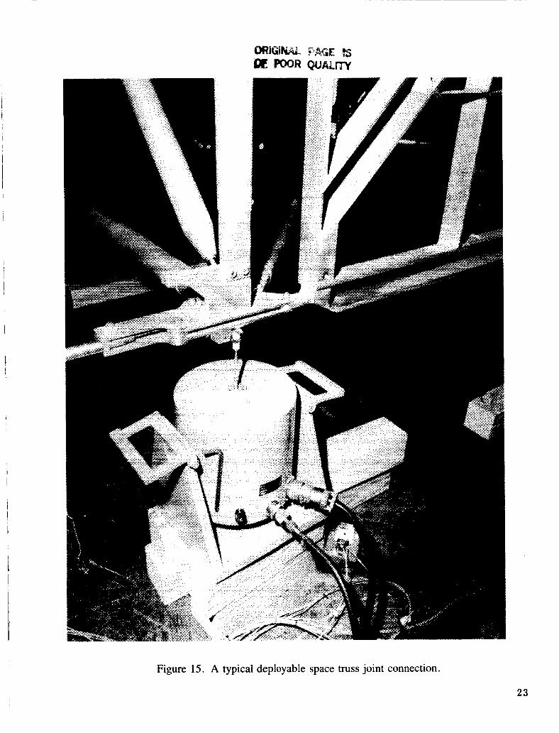
Figure 15. A typical deployable space truss joint connection.
23

v) v) w z
.. w I- O z
24
Y
.M c 0
Y
.w c 0 c,
w

v) w Q z T 0
a
I '
fi c( a c v1
c 0
a
a 8 k U U
s c a
25
cases, it may be necessary to update analytical models using experimental results. As the prototype experi- mental data become available, analytical iterations of this nature will become an integral part of the Phase I1 program. Deployable truss elements, crew modules, solar arrays, antennas, etc., will form the component base along with the necessary damping and isolation systems. Subassemblies will comprise multiple con- figurations of these prototype building blocks.
Testing of system subassemblies will be extremely complex. Two obvious problems to address are flexibility and nonsymmetry . Linking together of appendages, such as truss elements, will reduce the assemblage flexibility to limits where the structure may not be able to support its own weight in a 1-g environment. Dynamic tests will require unloading of gravity effects using the space structure suspension systems developed in Phase I . The nonsymmetry of many configurations will further complicate the tests by coupling together the vibration states of the torsional bending and axial modes. Subassembly tests will also provide the configuration necessary for testing, evaluating, and controlling large scale deflection caused by dynamic motion. Although the subassembly testing phase poses many unique problems, this program provides the designer with a powerful tool for simulating the dynamics of a full-scale Space Station.
2. Controls and Structural Dynamic Interaction Tests
Once the Phase I activity has been accomplished and a preliminary system design has been arrived at, a Phase I1 test architecture can be developed. This would probably be composed of a mixture of passive and active damping devices along control systems necessary for positioning solar arrays, antennas, tele- scopes, and tracking devices.
The large size of the Space Station and the light weight and high flexibility of the structure will result in very low frequencies with densely spaced modes. If the control system is designed so that it does not interact with the Space Station’s structure, then the control system frequency must be much less than the first modal frequency. The Space Station’s first modal frequency is expected to be less than 1 Hz. Control systems of a higher frequency response may be required to be compatible with mission objectives and to take advantage of available cost effective hardware. Thus, the control system frequencies will be imbedded in the range of modal frequencies of the Space Station. The control system will interact and affect the structural system’s dynamics. Thus, the control system can actually excite the Space Station. It is necessary to develop interactive control systems which can enhance the structural design and not be a detriment. Experimentation must be pursued to investigate the parametrics important to develop an interactive control system for the Space Station.
One question that needs to be answered for the Space Station is what kind of control scheme can be applied successfully? Can the control system architecture be centralized, decentralized, or distributed?
A centralized concept implies that the sensors and effectors are in close proximity of one another. The decentralized concept has independent remotely located sensors and controllers. The distributed con- trol concept uses remotely located sensoys, but the controllers are all coupled together. The above concepts need to be tested for feasibility. This testing would seek to identify the best control method for a particular mission defined application.
26
As the Space Station design progresses, these test subassemblies will be upgraded to include engineering models of test structures and bread board version of the active control elements. This phase would continue into the operational time period of the station and provide the means for verification of inflight changes and modifications.
3. Ground Testing of On-orbit Test Procedures and Equipment
As the actual prototype Space Station components become available, it is imperative that test proce- dures necessary for orbital testing be developed and rehearsed on the ground. Also, all flight ready test equipment must be developed and constructed. This equipment must be thoroughly tested on the ground.
This test development will draw heavily on the experience gained from Phase I testing. The major difference at this stage is that flight ready techniques and equipment must be developed and verified. MSFC staff must also become involved with the training of astronaut personnel. This training will involve instruc- tion and rehearsal of the on-orbit test techniques and equipment usage. At this stage of rehearsal, MSFC can implement any needed changes to the procedure to ease the astronaut’s workload and to improve the quality of the testing.
4. Zero-G Suspension Simulation
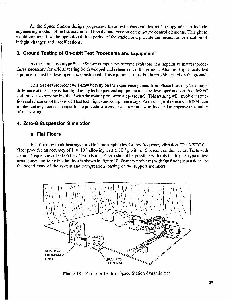
a. Flat Floors
Flat floors with air bearings provide large amplitudes for low frequency vibration. The MSFC flat floor provides an accuracy of 1 X g with a 10 percent random error. Tests with natural frequencies of 0.0064 Hz (periods of 156 sec) should be possible with this facility. A typical test arrangement utilizing the flat floor is shown in Figure 18. Primary problems with flat floor suspensions are the added mass of the system and compression loading of the support members.
allowing tests at
PROCESSING UNIT
Figure 18. Flat floor facility. Space Station dynamic test.
27
b. Cable Suspensions
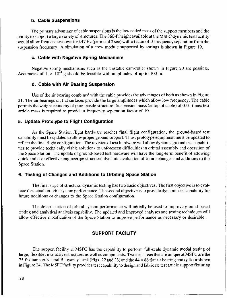
The primary advantage of cable suspensions is the low added mass of the support members and the ability to support a large variety of structures. The 360-ft height available at the MSFC dynamic test facility would allow frequencies down to 0.47 Hz (period of 2 sec) with a factor of 10 frequency separation from the suspension frequency. A simulation of a crew module supported by springs is shown in Figure 19.
c. Cable with Negative Spring Mechanism
Negative spring mechanisms such as the unstable cam-roller shown in Figure 20 are possible. Accuracies of 1 X g should be feasible with amplitudes of up to 100 in.
d. Cable with Air Bearing Suspension
Use of the air bearing combined with the cable provides the advantages of both as shown in Figure 21. The air bearings on flat surfaces provide the large amplitudes which allow low frequency. The cable permits the weight economy of pure tensile structure. Suspension mass (at top of cable) of 0.01 times test article mass is required to provide a frequency separation factor of 10.
5. Update Prototype to Flight Configuration
As the Space Station flight hardware reaches final flight configuration, the ground-based test capability must be updated to allow proper ground support. Thus, prototype equipment must be updated to reflect the final flight configuration. The revision of test hardware will allow dynamic ground test capabili- ties to provide technically viable solutions to unforeseen difficulties in orbital assembly and operation of the Space Station. The update of ground-based test hardware will have the long-term benefit of allowing quick and cost effective engineeripg structural dynamic evaluation of future changes and additions to the Space Station.
6. Testing of Changes and Additions to Orbiting Space Station
The final stage of structural dynamic testing has two basic objectives. The first objective is to eval- uate the actual on-orbit system performance. The second objective is to provide dynamic test capability for future additions or changes to the Space Station configuration.
The determination of orbital system performance will initially be used to improve ground-based testing and analytical analysis capability. The updated and improved analyses and testing techniques will allow effective modification of the Space Station to improve performance as necessary or desirable.
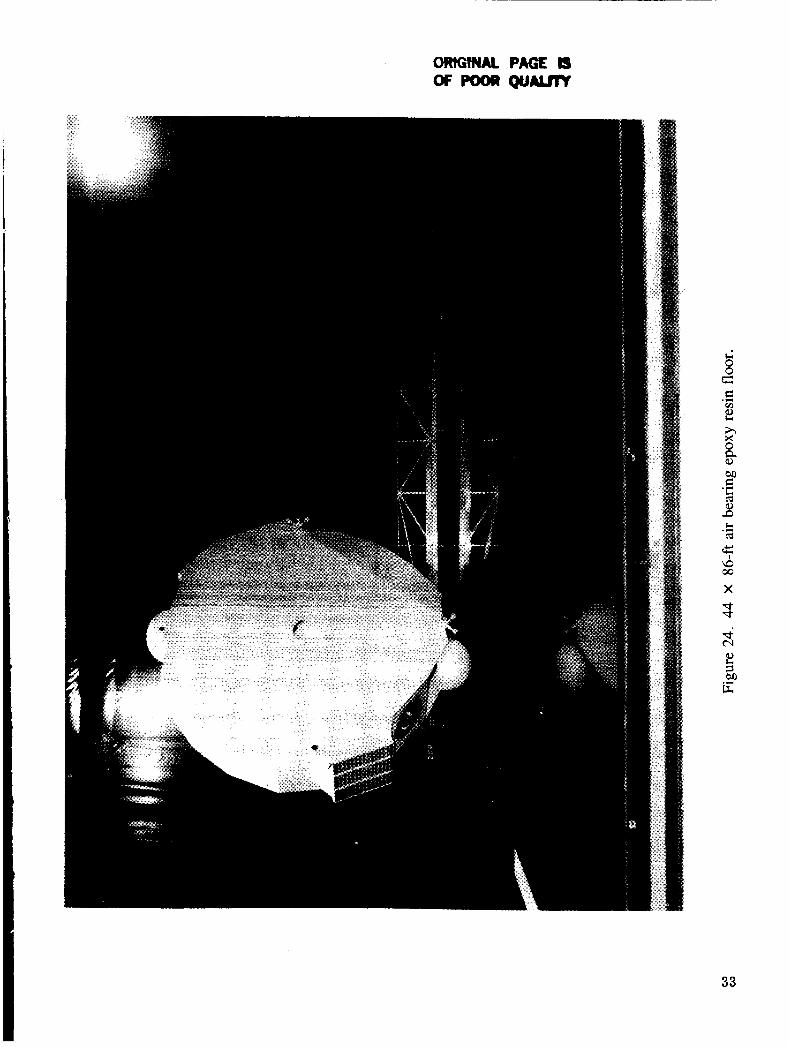
SUPPORT FACILITY
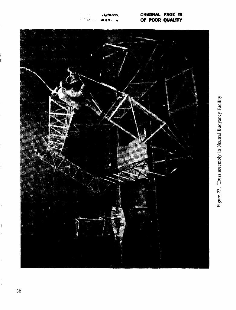
The support facility at MSFC has the capability to perform full-scale dynamic modal testing of large, flexible, interactive structures as well as components. Two test areas that are unique at MSFC are the 75-ft-diameter Neutral Buoyancy Tank (Figs. 22 and 23) and the 44 x 86 flat air bearing epoxy floor shown in Figure 24. The MSFC facility provides test capability to design and fabricate test article support fixturing
I I I I I
I I
I I I
I I
I
I I I I I
I I L!
W
c
I
8 N
5
29

ARTICLE CII C A M SURFACE
ROLLER
Figure 20. Cable support and negative spring mechanism.
AIR SUPPLY u r F B E A R I N G
\\
T-- c---- CABLE
ARTICLE u Figure 21. Hybrid cable and air bearing suspension system.
30

QRtUMl. PAGE fS OF poolp QUALm
h 0
h 0 s P
31
32
33
h ” . L . 1 .
and suspension systems tem,arepr@&onstraints. The excitation techniques have been developed along with the data acquisition, the data reduction, and analysis methods to acquire structural dynamic characteristics for low frequencies, unsymmetrical, high modal density, lightweight structures. This cap- ability can all be performed by in-house personnel.
The present test facility capability is as follows:
0 Large Scale Test Facilities
- Building 4619 Structures and mechanisms.
- Building 4550 Structural test facility.
- Building 4705 Machine shop/Neutral Buoyancy Simulator.
- Building 4708 Engineering and Development Lab.
- Building 4755 High Bay Assembly Facility.
An aerial view of the test facilities is shown in Figure 25.
0 Dynamic Testing Techniques
- Sine
- Random
- Impact
0 Exciters
- 1/16-in. stroke at 1-lb force to 9-in. stroke at 20,000-lb force.
Data Acquisition
- 250 triaxial measurement points.
- Roving and multiple point accelerometers.
Data Analysis
- Hewlett-Packard multi-sine control (MSC) software.
- Hewlett-Packard modal I1 Software.
- University of Cincinnati realtime executive (RTE) modal system software.
- University of Cincinnati multi-point random (MPR) software.
34

ORIGINAL PAGE 1s of: POOR Q U A W
35
0 Data Presentation .’-- , , f
- Frequency response function (A/F) plotted in coincident/quadrature components.
- Nyquist.
- Modal parameters (modal coefficients, frequencies, damping).
- Mode shape plots.
0 Modal System Hardware
- Hewlett-Packard 5423A (3) structural dynamic analyzer.
- Hewlett-Packard 5451B (1) Fourier analyzer.
- Hewlett-Packard 545 IC (2) Fourier analyzer.
- Hewlett-Packard 9845C (1) desktop computer.
- Hewlett-Packard 9826 (1) desktop computer
- Selective Electronic, Inc. FSC 6625 (1) two-channel remote sensor system.
Additional modal test capabilities are being developed under contract with the University of Cincin- nati. These capabilities include the development of multi-shaker input for random testing and use of array processors to eventually process modal data as they are acquired. These additions will reduce test time required and improve the ability to excite all possible modes of vibration, in particular those that are unsymmetrical with high coupled modal density. Also, under contract with Cincinnati is for them to provide time domain techniques for analyzing structures without external forces applied or for free decay structures. The two techniques that will be available are:
1. Poly Reference Technique
2. Ibrahim Time Domain Approach.
This type of technique will be a requirement for on-orbit dynamic testing as the excitation force or forces will usually be unknown.
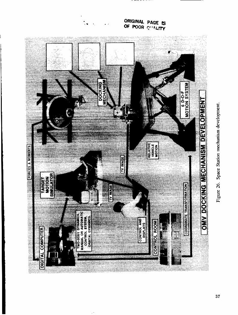
A Robotic system facility is available to provide testing of lightweight, very flexible, low frequency structures unable to support its own weight. The facility has a 4,000 ft2 (44 X 86 ft) air bearing epoxy resin floor as shown in Figure 24. A sound proof control and display room is also available. The test articles could be supported on air bearing gimbals to simulate zero-g. The facility will utilize a VAC’s 11750 computer and an Evan’s Southerland PS 330 graphics system. Available also is a 6 degree-of-freedom motion dynamic simulator depicted in Figures 26 and 27. This system will be used in the investigation of docking dynamics and closed loop control system operations. The system features a hydraulically powered platform which provides a 6 degree-of-freedom motion to drive test articles. Forces and moments are mea- sured on the test article and fed to the computer and then back to the platform for a closed loop system. System operation will utilize a dedicated VAX computer.
36
c 0 cd .+ Y
G
37

c 0 .r( c,
E
. -
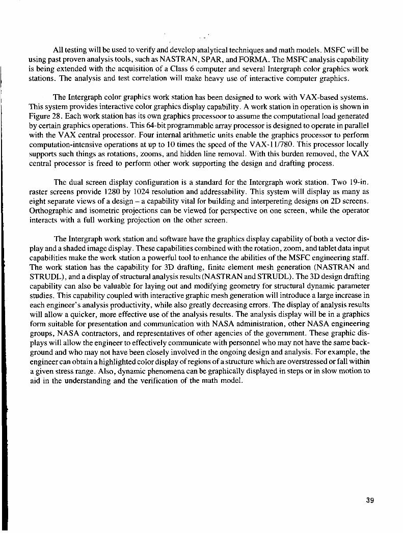
All testing will be used to verify and develop analytical techniques and math models. MSFC will be using past proven analysis tools, such as NASTRAN, SPAR, and FORMA. The MSFC analysis capability is being extended with the acquisition of a Class 6 computer and several Intergraph color graphics work stations. The analysis and test correlation will make heavy use of interactive computer graphics.
The Intergraph color graphics work station has been designed to work with VAX-based systems. This system provides interactive color graphics display capability. A work station in operation is shown in Figure 28. Each work station has its own graphics processoor to assume the computational load generated by certain graphics operations. This @-bit programmable array processor is designed to operate in parallel with the VAX central processor. Four internal arithmetic units enable the graphics processor to perform computation-intensive operations at up to 10 times the speed of the VAX-I 1/780. This processor locally supports such things as rotations, zooms, and hidden line removal. With this burden removed, the VAX central processor is freed to perform other work supporting the design and drafting process.
The dual screen display configuration is a standard for the Intergraph work station. Two 19411. raster screens provide 1280 by 1024 resolution and addressability. This system will display as many as eight separate views of a design - a capability vital for building and interpereting designs on 2D screens. Orthographic and isometric projections can be viewed for perspective on one screen, while the operator interacts with a full working projection on the other screen.
The Intergraph work station and software have the graphics display capability of both a vector dis- play and a shaded image display. These capabilities combined with the rotation, zoom, and tablet data input capabilities make the work station a powerful tool to enhance the abilities of the MSFC engineering staff. The work station has the capability for 3D drafting, finite element mesh generation (NASTRAN and STRUDL), and a display of structural analysis results (NASTRAN and STRUDL). The 3D design drafting capability can also be valuable for laying out and modifying geometry for structural dynamic parameter studies. This capability coupled with interactive graphic mesh generation will introduce a large increase in each engineer’s analysis productivity, while also greatly decreasing errors. The display of analysis results will allow a quicker, more effective use of the analysis results. The analysis display will be in a graphics form suitable for presentation and communication with NASA administration, other NASA engineering groups, NASA contractors, and representatives of other agencies of the government. These graphic dis- plays will allow the engineer to effectively communicate with personnel who may not have the same back- ground and who may not have been closely involved in the ongoing design and analysis. For example, the engineer can obtain a highlighted color display of regions of a structure which are overstressed or fall within a given stress range. Also, dynamic phenomena can be graphically displayed in steps or in slow motion to aid in the understanding and the verification of the math model.
39
rA V
a an
T E
40
I . , Carleton J. Moore, John S . Townsend, arid Edward W. Ivey
1. PERFORMING ORGANIZATION NAME AND ADDRESS 10. WORK UNIT NO. M-555
Space Station Structures and Dynamics Test Program
I 1 1 . CONTRACT OR GRANT NO. , George C. Marshall Space Flight Center
Marshall Space Flight Center, Alabama 35812 13. TYPE OF REPORi. & PERIOD COVERED
March 1987 6. PERFORMlNG ORGANIZATION CCOE
. REPORT NO. 2. GOVERNMENT ACCESSION NO. NASA TP-2710
1. TITLE AND SUBTITLE
I 1 8. PERFORMING ORGANIZATION REPOR r P r . AUTHORlSI
3. RECIP IENT 'S CATALOG NO.
5. REPORT DATE
#IF. (02 thh pa.) 21. NO. OF PAGES
45
22. PRICE
A0 3
2. SPONSORING AGENCY NAME AND ADDRESS
19. SECURITY CLASSIF. (d thio t o e d \
Unclassified
National Aeronautics and Space Administration Washington, D.C. 20546
20. SECURITY CLA
Unclassified
Technical Paper
1.1. SPONSORING AGENCY CODE
I 5. SUPPLEMENTARY NOTES
Prepared by Structures and Dynamics Laboratory, Science and Engineering Directorate.
6. ABSTRACT
The design, construction, and operation of a low-Earth orbit Space Station poses unique challenges for development and implementation of new technology. The technology arises from the special requirement that the station be built and constructed to function in a weightless environment, where static loads are minimal and secondary to system dynamics and control problems. One specific challenge con- fronting NASA is the development of a dynamics test program for (1) defining Space Station design requirements, and ( 2 ) identifying and characterizing phenomena affecting the station's design and develop- ment. A general definition of the Space Station dynamic test program, as proposed by MSFC, forms the subject of this report.
The test proposal, as outlined herein, is a comprehensive structural dynamics program to be launched in support of the Space Station. The test program will help to define the key issues and/or problems inherent to large space structure analysis, design, and testing. Development of a parametric data base and verification of the math models and analytical analysis tools necessary for engineering support of the station's design, construction, and operation provide the impetus for the dynamics test program. The philosophy being to integrate dynamics into the design phase through extensive ground testing and analyti- cal ground simulations of generic systems, prototype elements, and subassemblies. On-orbit testing of the station will also be used to define its capability.
17. KEY WORDS
Space Station Modal Testing Structural Testing Large Space Structures
18. DISTRIBUTION STATEMENT
Unclassified-Unlimited
Subject Category: 39