space-related high-power tracking …nsarchive2.gwu.edu/nsaebb/nsaebb501/docs/ebb-12.pdf ·...
TRANSCRIPT

GERY
LYSIS
IS ION
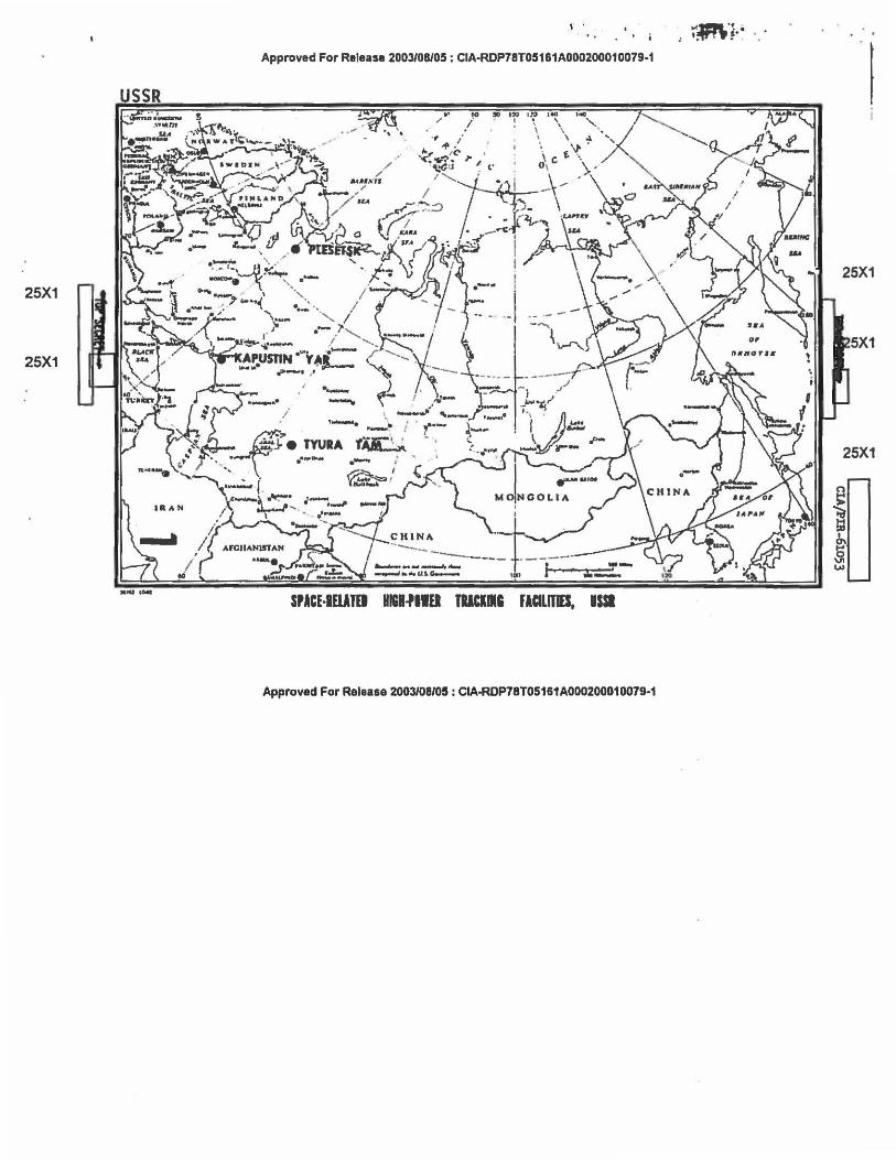
SPACE-RELATED HIGH-POWER TRACKING
FACILITIES, . TYURATAM, KAPUSTIN YAR,
A N D P L E S ET S K , U S S R
Oeclass Review by NIMA/000
CIA/PIR 61 05 3
DATE ~~;:~~r-1965 .. ..,_, ~(Q) D COPY ,..,....., ........... ~ . ........................ ~ .. ...... II
Approved For Release 2003/08/05: CIA-RDP78T05161A00028o1,~~~9-1
25X1
25X1
I .
'.
Approved For Release 2003/08105: CIA-RDP78T05181A000200010079-1
.. /
fO !ID I"JJ I~ l to
/ I i
SPACE-IWTO IIII.PIIU TUCIIIC JICILIJIS. ISSI
Approved For Release 2003/08/05: CIA-ROP78T05161AOD0200010079-1
.... .. !P.\ ..
•. ~-
25X1
5X1
25X1

1 ~ved For Release ~~P78jr05161A000200010079-1 L_____j I
CIA IMAGERY ANALYSIS DIVISION c!AjPffi-61053
SPACE-RELATED HIGH-PCMER TRACKING FACILITIES
TYURATAM, KAPUSTIN YAR, AND PLESETSK, USSR
Preface
Three unusual electronic facilities were recently identified in the USSR aod subsequently designated 11Nev Type Interferometers." CIA/IMJ photo analysts believe that, although interferometric techniques may be used at these facilities, they are electronically active rather than passive as is the case in most Soviet interferometers.
This report describes these installations as imaged onl J photography and in addition sets forth some functional and operations theories. It is emphasized that these are thoughts and ideas as set forth by CIA/IAD photo analysts and are not intended to be either tentative or. definite conclusions as to the function or operation of the electronics system in question. In short, this report is meant only to disseminate photographic intelligence and theories on these facilities so that their significance may be further evaluated.
All measurements in this report have been made by the CIA/IAD analyst. They should not be construed as being mensuration data compiled by the NPIC/ Technical Intelligence Division. They are considered to be accurate within plus or minus five feet or five percent, whichever is greater.
Introduction
Three large sophisticated tracking facilities, which could be capable of supporting Soviet space flights have been recently identified in the USSR. All of these facilities are located at major Soviet missile installations (Figure l). Construction of two of them vas started concurrentlr during the first quarter of 1965 at the Tyuratam Missile Test Center {TTMTC) and at the Kapustin Yar Missile Test Center {KYMTC). Construction of the third facility, at the Plesetsk ICBM Complex, commenced during the third quarter of 1965.
-1-
~· Approved For Relea·semfl!8~ P.-RDP78T05161A000200010079-1

.z(r- ··
·· ... . . ,, . ·~~
·~· ·t:
' . I .. • l ·~


CIA IMAGERY ANALYSIS DIVISION
I f c!A/PIR-61053
At their present respective stages of construction, all three facilities appear to have sUnilar components in respect to size and to intrasite location (Figures 2, 3, and 4). The only difference between facilities thus far isolated is the orientation of the sites with respect to north. The following table gives pertinent data on these installations.
On the basis of the combination, quantity, and spacing uniformity ot·the antenna supports (as yet, no antennas have been installed), these facilities are believed to have a function of tracking. They are believed to be spacerelated because of location, construction timing, and antenna orientations and furthermore are believed to be high-power because of control building size, cooling structures, and use of large waveguides. These waveguides were considered and rejected as combination access/cableways or solely cableways. Rejection is due to no visible requirement for access and overdesign as cableways. The emount of cables which could be placed in such a cableway is astronanical caupared to the size and type of structure at 1 ts terminus. use of these tunnels solely as waveguides also appears incredulous when considering conventional antennas on the terminal structures. Although no photographic evidence exists at this ti~e, these tunnels may be combination waveguide/ cableways, portions of which are designed for antennas not yet under construction. In any event, the portion of the tunnel allotted for waveguides . would be major. Hence, in this report, these tunnels are described as waveguides.
-2-
Approved For Release 2Q~ ... ~P78T05181A00020001 0079·1
----Ap-p-ro_v ..... r For Rarea••ray.v~ 5161A000200010079-1
CIA IMAGERY AN.Al. YSIS DIVISION CIA/PIR-ol053
Description and Discussion
In order to avoid repetition of descriptions, because of the near identity of these faci1ities, the sites will be discussed in the following paragraphs as one composite installation. Speclf;r sites will be mentioned only when dissimilarities exist.
Each facility is road served and is secured by fencing that encloses a trapezoidal area of approximately 123 acres. The location of trenching and structures creates a definite signature referred to by some analysts as a "Bow and Arrow" (Figure 5) .
The major structure at the facility is a centrally located control building 105 feet square and 35 feet high. Th~s building has a step roof vith venti1ators and ~t least tvo elevator shafts. Four floors are suspected with a total floor space of approximately 40,000 square feet. Associated with this building are two probable multiple fan cooling structures. Three subsurface waveguides extend from the control building to probable antenna bases. The control building is positioned within the facility so as to keep trenching for the waveguides to a minimum. Two other single-story support buildings, 105 by 45 and 80 by 6o fee~ are located near the control building . A 6o by 30 f')ot security building, walled vehicle parking area, and possible microwave tower 8o feet high are positioned at the entrance to the facility. Also located within the secured area at the Tyuratam facility are two large very shallow excavations near the control buUding which may become water treatment areas. A ditch para1lels the entrance road and leads to one of the support buildings. This ditch may be utilized for either a power or a water 1ine. At Tyuratam there is also some evidence of nev scarring from a nearby large power line indicating the possibility of the start of construction of a power source for the facility.
No housing or support areas have been identified in connection vi th these facilities, however, ample facilities cf this type are available nearby.
At least three suspect antenna types with a total of 32 individual antenna positions are under construction in the facili~y. Although no antennas are as yet installed, the structures on which the antennas will be placed are present.
-3-

1
1
1
CIA IMAGERY AN~ YSIS DIVISION I I CIA/PIR-61053
Antenna analysis is based on previously observed Soviet construction practices at other locations, however, the multiple application and int ration of different antennas is unique and without precedence on
photography. For ease of discussion, the suspect antenna types ha e een arbitrarily designated A, B, and C and will be described individually in the following paragraphs.
Suspect Antenna Type A
Type A is composed of nine antennas forming two major base lines with a configuration of both a "plus11 and a large 11L'! At the Tyuratam and Kapustin Yar facilities, these base lines are aligned north south and east/ west. At Plesetsk, the alignment is Each antenna position consists of a square s rue ure on a s e with a flat roof I Iabove the ground. A circle 1 1 feet in diameter, appears on the roof of each structure. It does not appear that antennas are as yet installed, however, based on past Soviet construction practice, they will be installed on separate pedestals, probably on the circles observed on each structure. Each antenna structure is served by a large buried waveguide which is connected to the control building. These waveguides are in real1 ty large tunnels, 10 feet wide, and each waveguide bas been covered by a stabilized earth mound with a flat top 4o feet wide. The layout of the Type A antennas is reminisent of interferometer designs in that the configuration relationship of the 'plus11 to the "L" and the spacing between antennas is suggestive of pertinent wavelength considerations. However, the large size of each antenna structure and of the enormous waveguides suggest a very-high-power active integrated system far outstripping the requirements for a 'passive interferometer. Although the large mounds covering the waveguides which serve these antennas are probably meant to do just that, their resemblance to stabilized earth platforms used to support large antenna arrays such as BEN ROOST cannot be ignored. These mounds appear to grossly exceed any shielding requirements required for covering waveguides and thus the possibility of their being supports for additional antennas should be seriously considered.
The baselines formed by the suspect Type A antennas have an .overall length of 2,150 feet. The portion of each base line which makes up the "plusn configuration is divided into segments of 215 feet or one-tenth of the overall length. A graded-earth circle, 265 feet in radius, surrounds the Type A antennas which form the nplus" configuration.
-4-
Approved For Release 20i1"~ OP78T05161A000200010079-1
'-----A-p-pr .... red For Rele•••'j!~RDP/B! os1&1Aooo20oo1oors-1
CIA IMAGERY ANALYSIS DIVISION
CIA/ r IR -010) j
Suspect Antenna Type B
Type B is composed or four groups of five antennas each, forming a square with diagonals of I l(a distance one-tenth that of the larger diagonal). Each group of five is served by two narrow parallel cable or waveguide ditches leading from the vic~nity of' the nearest Type A antenna. Within each group of five antennas, a small cable trench leads from the central antenna to each of the four corner ones. Each antenna structure isl I square.
Although each group of suspect Type B antennas has a definite geometric relationship to other components of the facility, it should be pointed out that each individual group of five structures also bears some resemblance to footings for a guyed tower such as a vertical radiator. This possibility is considered unlikely but cannot be entirely discounted.
Due to their location and alignment, the Type B antennas are believed to be related to the Type A antennas in some manner. Two of the Type B groups are located at the mid-point of the two Type A major baselines. The other two Type B groups are positioned along projected extensions of the Type A maJor base lines. Graded earth strips extend to each group of Type B antennas from the graded earth circle which surrounds the "plus" configuration. These earth strips have the same width as the mounds covering the waveguides associated with Type A antennas. A similar graded earth strip connects the two Type A antennas which are at ~he extremities of the "L" formed by the two baselines. A trench was never observed at the location of any of these strips. However, it is possible that this stage was missed due to lack of sui table photographic ccverage 11t the proper time.
Suspect Antenna Type C
Type C is composed at the present time of three cylindrical antenna support structures. Two or these structures bracket the "plus" configuration of the Type A antennas and are connected to the central Type A structure by small cable trenches. The other Type C antenna structure is located near the control building without any apparent reference to oche a ennas. Each structure is at present a vertical cylindrical wall in diameter and 45 feet high. The Type C antennas which will be insta led on the top of these structures may be helix arrays if there ·is a requirement for telemetry,
-5-
Approved For Releas<f~ A-RDP78T05161A000200010079-1

1 Approved ,or Release 200feP'
CIA IMAGERY ANALYSIS DIVISION CIAJPffi-61053
yagi arrays if a requirement for communications vith a manned space probe exists, or parabolic dish reflectors for additional tracking.
At this point it should be restated that all of these facilities are still under construction and that no actual antennas have been observed at any one of the three. As construction continues and additional coverage is obtained of Tyuratem, Kapustin Yar, and Plesetsk, the design of these facilities vill become more apparent and only then will it be possible to finely define the function of these high pover tracking facilities.
REQUIREMENT
Z/58/65
CIA/IAD PROJECT
30448-6
REFERENCES
-6- ~-----------------------------,
DP78T05161A00020001 0079-1
