space reactor design overview - ntrs.nasa.gov
TRANSCRIPT

2
Basics of Nuclear Systems
Long history of use on Apollo and space science missions
44 RTGs and hundreds of RHUs launched by U.S. since the 1960s
Heat produced from natural alpha () particle decay of Plutonium (Pu-238)
Used for both thermal management and electricity production
5.5 MeV
Pu-238
U-234
(He-4)
Fissile Nucleus (U-235)
Neutron
Product Nuclei (KE 168 MeV)
Neutrons ( 2.5)
190 MeV*
U-235
U-235
Radioisotope Decay (Pu-238) Fission (U-235)
Heat Energy = 0.023 MeV/nucleon (0.558 W/g Pu-238)Natural decay rate (87.7-year half-life)
Heat Energy = 0.851 MeV/nucleonControllable reaction rate (variable power levels)
Used terrestrially for over 70 yearsFissioning 1 kg of uranium yields as much energy as
burning 2,700,000 kg of coalOne US space reactor (SNAP-10A) flown (1965)
Former U.S.S.R. flew 33 space reactorsHeat produced from neutron-induced splitting of a
nucleus (e.g. U-235)At steady-state, 1 of the 2 to 3 neutrons released in the
reaction causes a subsequent fission in a “chain reaction” process
Heat converted to electricity, or used directly to heat a propellant

Fissile Nucleus (U-235)
Neutron
Product Nuclei (168 MeV)
Neutrons ( 2.5)
190 MeV*
U-235
U-235
180 MeV prompt useful energy (plus 10 MeV neutrinos) - additional energy released in form of fission product beta particles, gamma rays, neutron capture gammas (~200 MeV total useful)
• Neutron absorbed by heavy nucleus, which splits to form products with higher binding energy per nucleon. Difference between initial and final masses = prompt energy released (190 MeV).
—Fissile isotopes (U-233, U-235 and Pu-239) fission at any neutron energy—Other actinides (U-238) fission at only high neutron energies
• Fission fragment kinetic energy (168 MeV), instantaneous gamma energy (7 MeV), fission neutron kinetic energy (5 MeV), Beta particles from fission products (7 MeV), Gamma rays from fission products (6 MeV), Gamma rays from neutron capture (~7 MeV).
• For steady power production, 1 of the 2 to 3 neutrons from each reaction must cause a subsequent fission in a chain reaction process.
MaximumStability
Fusion
Fission
Nuclear Fission Process

4
Fission Introduction
• Creating a fission chain reaction is conceptually simple– Requires right materials in right geometry
• Good engineering needed to create safe, affordable, useful fission systems
• 1938 Fission Discovered• 1939 Einstein letter to Roosevelt• 1942 Manhattan project initiated• 1942 First sustained fission chain
reaction (CP-1)• 1943 X-10 Reactor (ORNL), 3500 kWt• 1944 B-Reactor (Hanford), 250,000 kWt• 1944-now Thousands of reactors at
various power levels
X-10 Reactor

5
Fission is Highly Versatile with Many Applications
• Small research reactors– Examples include 2000 kWt TRIGA reactor
recently installed in Morocco (< $100M)
• Advanced, high-power research reactors and associated facilities– Examples include the US Fast Flux Test,
EBR-II, ATR, HFIR
• Commercial Light Water Reactors 1,371,000 kWe (3,800,000 kWt)
• Space reactors– SNAP-10A 42 kWt / 0.6 kWe– Soviet reactors typically 100 kWt / 3 kWe
(some systems >150 kWt)– Cost is design-dependent

6
Fission is Highly Versatile with Many Applications (continued)
• Naval Reactors– Hundreds of submarines and surface ships
worldwide
• Production of medical and other isotopes
• Fission Surface Power– Safe, abundant, cost effective power on the
moon or Mars
• Nuclear Thermal Propulsion– Potential for fast, efficient transportation
throughout inner solar system
• Nuclear Electric Propulsion– Potential for efficient transportation throughout
solar system
• Highly advanced fission systems for solar system exploration

7
Typical Space Fission System Operation
• System power controlled by neutron balance
• Average 2.5 neutrons produced per fission– Including delayed
• Constant power if 1.0 of those neutrons goes on to cause another fission
• Decreasing power if < 1.0 neutron causes another fission, increasing if > 1.0
• System controlled by passively and actively controlling fraction of neutrons that escape or are captured
• Natural feedback enables straightforward control, constant temperature operation
• 200 kWt system burns 1 kg uranium every 13 yrs
• 45 grams per 1000 MW-hr~1.0 m

70 80 90 100 110 120 130 140 150 16010-4
10-3
10-2
10-1
1
10
Mass Number
Fiss
ion
Yiel
d (%
)
• Fission events yield bimodal distribution of product elements.
• These products are generally neutron-rich isotopes and emit beta and gamma particles in radioactive decay chains.
• Most products rapidly decay to stable forms –a few, however, decay at slow rates or decay to daughter products which have long decay times.
• Example fission products of concern:
—Strontium-90 (28.8-year half-life)
—Cesium-137 (30.1-year half-life)
• Isotope amounts decrease by factor of 1,000 after 10 half-lives and 1,000,000 after 20 half-lives.
• Decay power 6.2% at t=0 (plus fission from delayed neutrons), 1.3% at 1 hour, 0.1% at 2 months (following 5 years operation).
Product Yields for Thermal Neutron (0.025 eV) Fission
of U-235
Fission Products
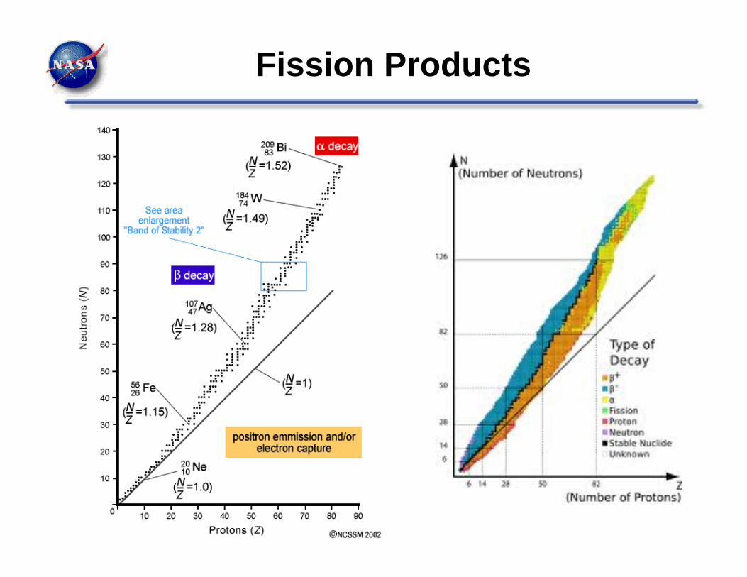
Fission Products

Gamma Radiation Shielding
I/Io = (B)e -/(x)
I = intensity
Io = initial intensity
B = Buildup Factor
e = 2.71828
= linear attenuation coefficient
= density
/ = mass attenuation coefficient
X = shield thickness http://physics.nist.gov/PhysRefData/XrayMassCoef/tab3.html

Mass Attenuation Coefficient (/ cm2/g) of Al, Fe, W, and U at 1.0, 3.0, and 8.0 MeV
Al Fe W U
1.0 MeV 0.0615 0.0600 0.0618 0.0790
3.0 MeV 0.0354 0.0362 0.0408 0.0445
8.0 MeV 0.0244 0.0299 0.0447 0.0488
Shield design must also take into account “buildup”, inelastic neutron scatter, gammas from neutron capture, geometry, thermal management, radiation damage, and other factors.

Neutron Radiation Shielding
Use hydrogenous material to slow neutrons.
Optimal Design – Avoid Capture Gammas, Gammas From Inelastic Scatter
6Li and 10B capture neutrons with no significant gamma radiation released.
Water is a great neutron shield, borated water a little better still!

Neutron Cross Sections
Measure of the probability of a particular neutron-nucleus interaction.
Property of the nucleus and the energy of the incident neutron.
Symbolized “”, common unit is “barn” = 1.0 x 10⁻²⁸ m2
Neutron Flux = nv = n = neutrons / m3v = neutron speed (m/s)
Reaction rate = N N = nuclei / m3
= neutron flux (neutrons / m2-s) = cross section (m2)

Comparison of Hydrogen and Deuterium Cross Sections


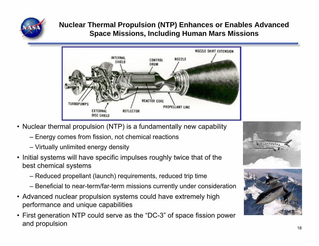
Nuclear Thermal Propulsion (NTP) Enhances or Enables Advanced Space Missions, Including Human Mars Missions
• Nuclear thermal propulsion (NTP) is a fundamentally new capability– Energy comes from fission, not chemical reactions– Virtually unlimited energy density
• Initial systems will have specific impulses roughly twice that of the best chemical systems
– Reduced propellant (launch) requirements, reduced trip time– Beneficial to near-term/far-term missions currently under consideration
• Advanced nuclear propulsion systems could have extremely high performance and unique capabilities
• First generation NTP could serve as the “DC-3” of space fission power and propulsion
18

19
• Propellant heated directly by a nuclear reactor and thermally expanded/accelerated through a nozzle
• Low molecular weight propellant – typically Hydrogen• Thrust directly related to thermal power of reactor: 100,000 N ≈ 450
MWth at 900 sec• Specific Impulse directly related to exhaust temperature: 830 - 1000 sec
(2300 - 3100K)• Specific Impulse improvement over chemical rockets due to lower
molecular weight of propellant (exhaust stream of O2/H2 engine actually runs hotter than NTP)
NOZZLE REFLECTOR
CONTROL DRUM
PUMPS
NUCLEAR REACTOR
HYDROGEN PROPELLANT
Major Elements of a Nuclear Thermal RocketNERVA Nuclear Thermal Rocket
Prototype
How Would Initial NTP Systems Work?

Base of LH2 Tank
HeliumPressurization
Bottles
StructuralSupports
Radiation Shield
Reactor Reflector
Reactor Core
Propellant Feed Line
Nozzle
Nozzle Extension
Propellant Bleedto Turbopump
Pressure Shell
Control Drum
Turbopump Exhaust(Attitude Control)
Control DrumActuators
Housing forTurbopumps
Cross Section
Control Drum
How Might Initial NTP Systems Work?
Reactor Core Fuel Elements Reactor Reflector
Note: Control drums rotate to control reactivity. Part of circumference covered with absorber and the rest is a reflector.

Control DrumsReflector
Core
NERVA Reactor Cross Section Fuel Segment Cluster
Control DrumAbsorber Plate
Previous NTP Engine Designs (Rover / NERVA)

22
20 NTP Engines Designed, Built, and Tested During Rover/NERVA

The most powerful nuclear rocket engine ever tested (Phoebus 2a) is shown during a high-power test. The reactor operated for about 32 minutes, 12 minutes at power levels of more than 4.0 million kilowatts.
NTP reference system is ~0.7 million kilowatts
PHOEBUS 2A NUCLEAR ROCKET ENGINE

NTP Start-up and Shut-down different than Chemical Engines
Based on NERVA Flight Design• Startup to steady state can take~1-2 minutes for conditioning, 30 sec for thrust buildup• Shut down time depends on steady state duration. 5 min run, I=.5min, M=16.5 hours. 20 minute run
time, I=3 minutes, M=49 hours
NERVA Engine Reference Data, S130-CP090290-AF1, Aerojet Nuclear systems Company, September 1970

Heat Generation After Shutdown

Nuclear Thermal Rocket Element Environmental Simulator (NTREES) Test of ORNL Fuel Element to >2800 K
26
Monitoring testing
Left: John Warren and NTREES designer and lead engineer Bill Emrich watch Mike Schoenfeld (obscured) prepare for testing

Fuel Details Fuel composition W-UO2-ThO2
Volume loading of Oxide (% vol.) 60.0ThO2 in the Oxide (%mol. ) 6.0Enrichment of 184W (% atom) 98.0Enrichment of 235U (% atom) 19.75 to 13.13Total Enriched W (kg) 376.0Total 235U (kg) 45.9Percent Theoretical Density (% TD) 97.0
Engine System Interface Information
Interface Point Flow Rate (kg/s)
Pressure (MPa)
Temp. (K)
Core inlet 17.9 6.93 291Core outlet 17.9 4.65 2698
Key Performance Parameters Nominal Isp (150:1 Nozzle) 896 Nominal Thrust (kN) 157.3 (~35k lbsf)Reactor Power (MW) 709.8Fuel Temperature Max (K) 2850.0
Reactor System Mass Fuel Mass (151 Elements) (kg) 1029.8Tie Tubes (150 Elements) (kg) 700.4Radial Reflector + Control Drums (kg) 618.6Axial Reflector (kg) 165.4Barrel+Vessel+Other Core Structure (kg) 308.4Total Mass (Excluding Shield) (kg) 2822.6
Space Capable Cryogenic Thermal Engine(Baseball Card as of 5/12/15, Rev. 1.0.0)
General DescriptionSCCTE is a A LEU W-UO2 cermet fuel, ZrH1.8 moderatednuclear thermal propulsion concept. SCCTE wasproduced with the Center for Space Nuclear Research‘sSpace Propulsion Optimization Code (SPOC).
97.0
0 cm
Control Drum
Fuel Element Moderator
Reflector
85.66 cm
Channel by channel power deposition in a
fuel element
Radial Enrichment Zones(gray is moderator)
Core Power Deposition(Radial peakingfactor of 1.089)
3.10 cm
Stennis Space Center
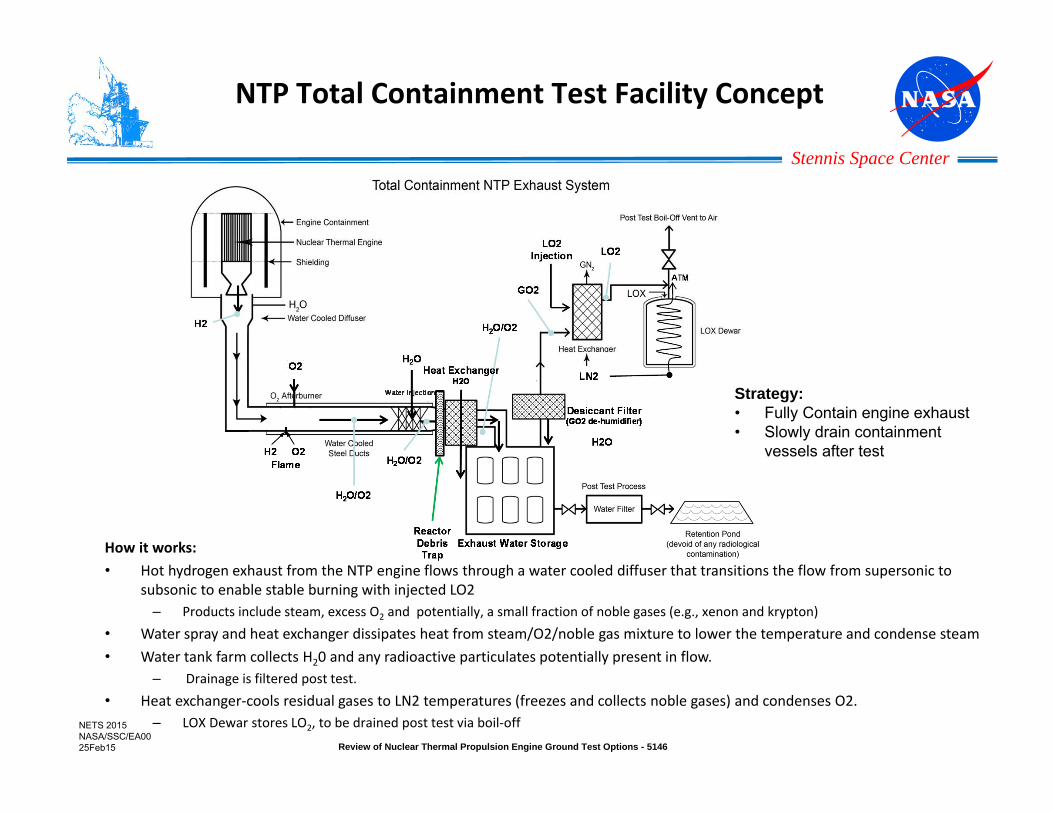
NTP Total Containment Test Facility Concept
How it works:• Hot hydrogen exhaust from the NTP engine flows through a water cooled diffuser that transitions the flow from supersonic to
subsonic to enable stable burning with injected LO2 – Products include steam, excess O2 and potentially, a small fraction of noble gases (e.g., xenon and krypton)
• Water spray and heat exchanger dissipates heat from steam/O2/noble gas mixture to lower the temperature and condense steam• Water tank farm collects H20 and any radioactive particulates potentially present in flow.
– Drainage is filtered post test.• Heat exchanger‐cools residual gases to LN2 temperatures (freezes and collects noble gases) and condenses O2.
– LOX Dewar stores LO2, to be drained post test via boil‐off
Strategy:• Fully Contain engine exhaust• Slowly drain containment
vessels after test
NETS 2015 NASA/SSC/EA0025Feb15 Review of Nuclear Thermal Propulsion Engine Ground Test Options - 5146

Stennis Space Center
Desiccant Filter
Water Injecti
on
Exhaust Water Storage
Total Engine Exhaust ContainmentConceptual System Design Layout and ROM Cost Estimate
NTP total containment ground test facility assumed to be located at SSC’s A3 Test Stand• Most of the infrastructure required by the NTP total containment ground test facility is already in place at A3:
• Tower, test cell, propellant, HPIW & data and controls infrastructure, the Test Control Center, electric power, etc. • Major modifications, procurements, and construction work will be required and are captured in the ROM estimate.
LO2H2OIPA
GN2
LO2
LH2
SSC A3 Test Facility
NETS 2015 NASA/SSC/EA0025Feb15 Review of Nuclear Thermal Propulsion Engine Ground Test Options - 5146
ROM estimate to prepare stand NTP for engine test: $172.5M, 4 years

Safe, Compact, Near-Term Fission Power Systems Could Help Enable Higher Power Fission Propulsion Systems
Science:
Exploration:
Jupiter Europa Orbiter~600 We (5 to 6 RPS)
Neptune Systems Explorer~3 kWe (9 Large RPS)
Kuiper Belt Object Orbiter~4 kWe (9 Large RPS)
Trojan Tour~800 We (6 RPS)
Site SurveyLanders
TeleoperatedRovers
ISRU DemoPlants
Remote SciencePackages
Comm RelayStations

Fission Can Provide the Energy for Either Nuclear Thermal or Nuclear Electric Propulsion Systems
• NEP Power System Performance Projections from 2001 STAIF Conference
• Fission Surface Power and Prometheus Concepts Superimposed
Near=Liq Metal Rx, Brayton, 1300K, 6 kg/m2, 200 Vac (Available ~10 yrs)Mid=Liq Metal Rx, Brayton, 1500K, 3 kg/m2, 1000 Vac (Available ~ 15-20 yrs)Far=Liq Metal Rx, Brayton, 2000K, 1.5 kg/m2, 5000 Vac (Available ~ 25-30 yrs)Cargo=Instrument rated shielding, 1.6x10^15 nvt, 1.2x10^8 rad @ 2 mCrew=Human rated shielding, 5 rem/yr @ 100 m, 7.5° half angle
FSPPrometheus
Chart courtesy Lee Mason, NASA GRC

Kilopower Technology Demonstration –Overall Objectives & Elements
• Big Idea:– A compact, low cost, scalable fission
power system for science and exploration
• Innovation:– KiloPower: novel integration of available
U235 fuel form, passive sodium heat pipes, and flight‐ready Stirling convertors
• Impact:– Provides Modular Option for HEOMD Mars
Surface Missions– Enables SMD Decadal Survey Missions– Reduces NASA dependence on Pu238
• Goals:– Nuclear‐heated system‐level test of
prototype U‐8Mo reactor core coupled to flight‐like Stirling convertors
– Detailed design concept that verifies scalability to 10 kWe for Mars
– Prepare for flight test of titanium‐water heat pipe radiator on ISS to verify Zero‐G performance
On‐orbit test of variable conductance heat pipe radiator under steady‐state & transient conditions
Full‐scale nuclear test of reactor core, sodium heat pipes, and Stirling convertors at prototypic operating conditions
1 to 10 kWeKilopower Technology
• 10X the power of current RPS• Available component technologies• Tested in existing facilities
32

Kilopower-Enabled Concepts Family
1 kW ThermoelectricApprox. 4 m long
600 kg or 1.7 W/kg
800 W StirlingApprox. 2.5 m long400 kg or 2 W/kg
• Common Design Features include: 0.5 to 10 kWe; >10 year design life Utilize available UMo reactor fuel from
DOE-NNSA Minimize thermal power to simplify reactor
design and control Incorporate passive Na heat pipes for
reactor heat transport Leverage power conversion technologies
from RPS Program (TE, Stirling) Design system so that it can be tested in
existing DOE nuclear facilities
10 kW StirlingApprox. 4 m tall
1800 kg or 5 W/kg
3 kW StirlingApprox. 5 m long750 kg or 4 W/kg
33
1 kWe‐class Technology Demonstration establishes foundation for range of systems and capabilities

Kilopower Reactor Technology Scales to Size Needed for 10 kWe
• Most reactor technology challenges are addressed with 1 kWe configuration UMo fuel casting, final machining, and geometric tolerances Core structural integrity, phase stability, and creep at operating temperature Heat pipe-to-core materials compatibility, diffusion, and interface coatings Heat transfer from core to heat pipes, and heat pipes to Stirling Verification of predictable reactivity feedback Model validation for core temperatures, power, and reactivity
34
4.3 kWt/1 kWe
28.4 kg U2350.09% Burnup8X 3/8” heat pipesApprox 4.5” dia x 9.5” tall
43.3 kWt/10 kWe
43.7 kg U2350.56% Burnup24X 5/8” heat pipesApprox 6” dia x 11” tall

Kilopower Thermal Prototype
• Kilopower Thermal Prototype is first of three steps to a nuclear ground demonstration Non-nuclear functional prototype with steel simulated reactor core Non-nuclear prototype with depleted uranium simulated core Nuclear demonstration with uranium reactor core
• Thermal prototype validates core geometry and heat pipe attachment method prior to build of depleted uranium simulated core Steel core thermal properties are close enough to uranium to validate heat pipe attachment
method under thermal load, and segmentation of core First of two electrically heated trials of heat pipe attachment methods tested at temperature
in vacuum
35
Stainless Steel Thermal Prototype Vacuum Tank Integration Integrated Assembly Test

Latest Configuration of 1 kWe KrustyNuclear Demonstration
36

Latest Configuration of 1 kWe KrustyNuclear Demonstration

Partner Organizations Investing in Kilopower
• DOE / National Nuclear Security Administration (NNSA) Nevada National Security Site Device Assembly Facility is being provided
without cost to NASA NNSA will own, keep, and dispose of Kilopower demonstration reactor core NNSA is contributing $0.5M in FY16 and $2M in FY17 to Kilopower
• HEOMD Significant interest from HAT for Evolvable Mars Campaign Providing time of Human Spaceflight Architecture Team (HAT) members for
Mars Kilopower Concept Development Possible Kilopower use on 2024-26 Mars ISRU Surface Demo
• Industry: Aerojet/Rocketdyne Committing Independent Research and Development funds in FY15 for reactor
core materials research and testing Interested in continued and broader partnership
• Other Government Agencies: ARPA-E Contracts awarded for 1 kWe residential power: GENerators for Small Electrical
and Thermal Systems (GENSETS) Two Stirling technology contracts could have direct benefit to Kilopower (Infinia
$3.7M, Sunpower $3.5M)38

39
• The volume of a toy marble could contain the mass of uranium providing the NTP energy for an entire human Mars mission
• Standing next to an NTP engine before launch for one year is less radiation than a diagnostic x‐ray
• NTP ground test regulations allow the maximum annual public dose from NTP testing to be equivalent to ~20 hours of plane flight, which is also equivalent to ~25% of the natural radiation from food.
NTP Facts
Nuclear Engine
Technicians

40
• Crews of nuclear submarines have lower radiation exposure than the general public above the water
• Using NTP for faster trip times to Mars exposes the astronauts to less galactic cosmic radiation
• NTP reactor fission products from the entire Mars mission is about equal to products formed after ~two weeks of runtime from a 10 MW college reactor
NTP Facts (Cont’d)

Deaths by TeraWatt Hours (TWh) *
Energy Source Death Rate (per TWh) Percent - World Energy /ElectricityCoal (electricity, heating, cooking) 100 26% / 50%
Coal (electricity -world average) 60 26% / 50%
Coal (electricity, heating, cooking) - China 170
Coal (electricity) - China 90
Coal - USA 15
Oil 36 36%
Natural Gas 4 21%
Biofuel / Biomass 12
Peat 12
Solar (rooftop) 0.44 0.2% of world energy for all solar
Wind 0.15 1.6%Hydro 0.10 (Europe death rate) 2.2%
Hydro (world including Banqiao dam failure) 1.4 (About 2500 TWh/yr and 171,000 Banquio dead)
Nuclear 0.04 5.9%
*Source: http://nextbigfuture.com/2011/03/deaths-per-twh-by-energy-source.html?m=1 5/13/2011
60% for coal for electricity, cooking and heating in China. Pollution is 30% from coal power plants in China for the particulates and 66% for sulfur dioxide. Mining accidents, transportation accidents are mostly from coal for electricity.

42
First Generation NTP Systems Could Help Enable Highly Advanced Propulsion Systems
LIQUID CORE NUCLEAR ROCKETSOLID CORE NUCLEAR ROCKET
Open-Cycle Gas Core Nuclear Rocket Closed-Cycle Gas Core Nuclear Rocket

Future Plans / Path Forward
• Space fission power and propulsion systems have the potential to enable ambitious missions throughout the solar system.
• Space fission power and propulsion will only be utilized if affordable and viable development strategies can be devised.
• Ongoing projects are focused on developing and demonstrating those strategies.
43