space-based solar power...
TRANSCRIPT
Space-Based Solar Power System
December 16, 2011 Jarred Vallbracht

i
Table of Contents
1 INTRODUCTION............................................................................................................................... 2
2 PROJECT DESCRIPTION AND GOALS....................................................................................... 3
3 TECHNICAL SPECIFICATIONS.................................................................................................... 5
3.1 SUNSAT........................................................................................................................................ 5 3.1.1 Solar Cell Arrays .................................................................................................................... 5 3.1.2 Power Conversion Hardware ................................................................................................. 6 3.1.3 Battery Backup System ........................................................................................................... 8
3.2 ORBIT........................................................................................................................................... 9 3.2.1 Parameters ............................................................................................................................. 9 3.2.2 Orbital Insertion and Station Keeping.................................................................................. 10
3.3 TELEMETRY AND CONTROL LINK............................................................................................... 11 3.3.1 Encoding and Encryption ..................................................................................................... 12 3.3.2 SunSat Antenna..................................................................................................................... 13 3.3.3 Ground Antenna ................................................................................................................... 14 3.3.4 Link Budget........................................................................................................................... 14
3.4 POWER TRANSMISSION LINK...................................................................................................... 15 3.4.1 Transmitter Dish Array......................................................................................................... 15 3.4.2 Rectenna ............................................................................................................................... 16 3.4.3 Link Budget........................................................................................................................... 17
4 DESIGN APPROACH AND DETAILS.......................................................................................... 19
4.1 SPACE HARDENING .................................................................................................................... 19 4.2 POTENTIAL IMPACTS .................................................................................................................. 20
4.2.1 Environmental ...................................................................................................................... 20 4.2.2 Existing Electronics .............................................................................................................. 22
4.3 OUTAGES ................................................................................................................................... 22 4.4 ASSEMBLING .............................................................................................................................. 23
5 TIMELINE ........................................................................................................................................ 24
6 BUDGET AND COST ANALYSIS ................................................................................................. 25
6.1 SUNSAT...................................................................................................................................... 25 6.2 LAUNCH ..................................................................................................................................... 25 6.3 GROUND COMMAND AND MONITORING..................................................................................... 26 6.4 COST SUMMARY ........................................................................................................................ 27
7 REFERENCES.................................................................................................................................. 28

2
1 Introduction
With the world’s population continuing to grow and global warming on the brink of
causing a dramatic shift in the Earth’s climate, development of a clean and reliable power
source has never been more urgent. Although numerous alternative energy sources have
been pursued, none of the technologies have taken off. However, technological
developments of the last twenty years have given new life to the idea of space-based solar
power as a means for meeting these demands.
Space-based solar power would bring numerous benefits over its terrestrial
counterparts. One of the major benefits is that the power generation will be clean. Unlike,
coal, oil, or natural gas based power plants; space-based solar power will only release
greenhouse gasses once, during launch. Furthermore, space-based solar power would
provide constant, sunlight at levels eight times greater than what can be harvested by
solar cells on Earth [1]. Given its clean production and constant free power source, space-
based solar power has the opportunity to redefine power production as we know it.

3
2 Project Description and Goals
The goal of this design is to design an economically feasible, end-to-end system for
harvesting solar energy from space and beaming it down to earth. Similar studies have
been done in the past by reputable organizations such as NASA and the Department of
Energy. Although those organizations found space-based solar power to be
uneconomical, new technological developments and multi-corporate cooperation have
changed the playing field.
The space-based portion of the system consists of a constellation of solar energy
harvesting satellites (referred to as SunSats) that collect solar power and transmit the
energy via a 5.8 GHz beam back to earth. An artist’s rendering of a SunSat can be seen in
Figure 1. Initially there will be eight of these satellites located in various geostationary
orbits (GEO) corresponding to their matching ground station. This will later expand to
include eight more during the second phase and will be modularly expandable afterwards.
Figure 1. A graphic representation of a SunSat in action

4
On earth, ground stations featuring large rectennas will be capable of converting the
broadcasted microwave frequency back into DC power. Once converted DC, the power
will then be transformed into AC and pumped into the electrical grid, at which point its
use becomes transparent to the end-user.

5
3 Technical Specifications
3.1 SunSat
The SunSats are required to produce radio frequency power at a constant rate with
minimum interruptions. The three key parts for doing so are: the solar cell arrays, the
power conversion hardware, and the battery backup system.
3.1.1 Solar Cell Arrays
Each solar cell array will consist of a thin film photovoltaic that can produce 16.8
kilowatts/kilogram. This material will be laid out in a circular pattern similar to the one
shown in Figure 1. The circle will be three kilometers in diameter and will provide five
gigawatts of power. A simple power density calculation shows that in order to produce 10
gigawatts of total power, approximately 595,238 kg of the thin film photovoltaic will be
required.
The solar arrays will be paired with a reflector array to help concentrate solar energy
onto the photovoltaic cells. The reflector array will also be laid out in a circular pattern
but will be five kilometers in diameter. The reflector array will consist of a support
structure layered in the equivalent of extremely reflective aluminum foil. Given an
assumed thickness approximately equal to a sheet of aluminum foil (0.02 mm), each
reflector array will have a mass equal to 1000 kg, not including support structure.
6
3.1.2 Power Conversion Hardware
The DC power produced by the SunSats will be beamed back to Earth at 5.8 GHz.
This frequency was chosen not only because of its minimal attenuation by rain (a system
constraint that cannot be controlled or avoided), but also due to the fact that many of the
most advanced and efficient hardware designs employ this frequency. Furthermore, the
higher frequency (i.e. using 5.8 GHz instead of 2.4 GHz) increases the gain of the
antennas used in the design and thereby the efficiency of the system.
When it comes to converting DC to RF energy, there are many options with varying
strengths and weaknesses. However, after filtering for products that can operate in the
gigawatt range and proposed 5.8GHz frequency, only two remain: klystrons and
magnetrons.
Klystrons are a mainstay for particle accelerators. A klystron works by accelerating a
beam of electrons in bunches through a cavity. RF energy is passed into the cavity and
the electron bunches that move through during an opposing magnetic field are
accelerated. The amplified signal then is directed toward a second cavity where it is
guided out of the device [13]. A diagram of the process is shown in Figure 2 below.
They are capable of producing high powers at efficiencies approaching 65% [14].

7
Figure 2. Diagram of a Klystron
The magnetron is known as a “cross-field” device due to its use of both electric and
magnetic fields. A cross section of the device is shown in Figure 3. Heat is applied to the
inner, circular cathode in the presence of a constant magnetic field. This causes the
ejection of energetic electrons which, upon contacting the negatively charged cavities in
the anode, are propelled circularly into the main cavity. This cycle causes the
amplification that occurs at the resonance frequency of the main cavity [12]. According
to a study by NASA and JPL published in 2000, they were able to develop a magnetron
with an efficiency of 85.5% [11]
Figure 3. Inner workings of a magnetron [12]

8
Given the higher efficiency of the magnetron, it was the only logical decision.
Despite any potential weight differences, the goal of the project is to provide as much
energy as possible to the ground stations. This can only be accomplished by transmitting
energy with the highest possible efficiency.
3.1.3 Battery Backup System
In order to maintain satellite connectivity during eclipses, each SunSat will be
equipped with a battery. NASA has previously performed a study on the various
rechargeable battery types that are being used in space applications [6]. Figure 4 and
Figure 5 were taken from the study. From these figures it is easy to conclude that Ag/Zn
batteries should be used due to their high power/weight density as well as their high
power/volume density.
Figure 4. Power/Weight density of rechargeable batteries used in space applications [6]

9
Figure 5. Power/Volume density of rechargeable batteries used in space applications [6]
Since the battery will only need to be used for a maximum of 70 minutes during peak
eclipse season [5] and will only power the minimum necessary hardware to maintain
connectivity to the satellite, it will not need to be very powerful. The minimum hardware
will include heaters for the electronics, the communication TWTA and antenna, as well
as various onboard computers and diagnostics.
3.2 Orbit
3.2.1 Parameters
Each SunSat will be located in a geostationary orbit. The benefits of geostationary
orbits are as follows:
10
• The SunSats will never go out of view
• The satellites’ transmitter dishes will not be required to move extensively
• The SunSats will avoid the large amount of debris located in lower orbits
• The rectennas will not be required to actively track the SunSats
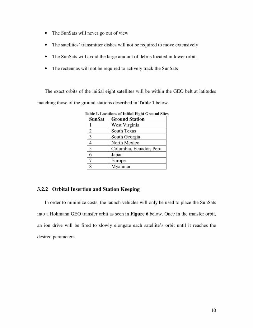
The exact orbits of the initial eight satellites will be within the GEO belt at latitudes
matching those of the ground stations described in Table 1 below.
Table 1. Locations of Initial Eight Ground Sites
SunSat Ground Station 1 West Virginia
2 South Texas
3 South Georgia
4 North Mexico
5 Columbia, Ecuador, Peru
6 Japan
7 Europe
8 Myanmar
3.2.2 Orbital Insertion and Station Keeping
In order to minimize costs, the launch vehicles will only be used to place the SunSats
into a Hohmann GEO transfer orbit as seen in Figure 6 below. Once in the transfer orbit,
an ion drive will be fired to slowly elongate each satellite’s orbit until it reaches the
desired parameters.

11
Figure 6. Hohmann transfer orbit [15]
In order to maintain the correct orbit of the SunSats, a certain amount of adjusting
will be required. Orbital adjustments will be accomplished through the use of three pairs
of low power thrusters (one pair for each axis).
There will also be four momentum wheels that will assist in attitude control of the
craft. Three of the momentum wheels will correspond to the x, y, and z axes while the
fourth will act redundantly by being inclined across all axes.
3.3 Telemetry and Control Link
In order to successfully inject the SunSats into their proper orbits and to ensure their
health, a telemetry and control link will need to be established that is separate of the
power transfer assembly. This link will be used for the following:
• Performing station keeping maneuvers

12
• Deploying the solar arrays and reflectors
• Monitoring the health of the spacecraft
• Commanding of the various on board systems and backups
Given the importance of this link, it will need to be capable of communicating with
the earth station no matter what orientation the satellite is in. Furthermore, to deter
dangerous cyber attacks and unapproved use, the link will need to be secure and difficult
to jam.
3.3.1 Encoding and Encryption
The telemetry and commanding link does not require a large amount of bandwidth,
but needs to be persistent throughout all weather conditions. To this end, S-band
frequencies of 3.4/3.5 GHz have been chosen as the carrier frequencies for the link.
These frequencies are set aside by the FCC for fixed service satellites such as the SunSats
and will therefore not require special permission to be acquired [7]. A total of 100MHz of
bandwidth on each link will provide ample room for telemetry and commanding. As an
added benefit these S-band frequencies are little affected by inclement weather. This will
allow the ground station to maintain link with the satellite even during severe weather.
A newly developed 1/2 rate, 2D 16-state forward error correcting code will be used to
provide redundancy in the communication link and help to bring the signal closer to the
Shannon channel capacity limit. This code has recently been implemented by iDirect [8],
and as such iDirect has been asked to assist in the codes implementation. The resultant

13
signal will then be encrypted using an Advanced Encryption Standard (AES) with a 256-
bit key, Elliptic Curve Public Key Cryptography, an NSA approved encryption standard
for sending data classified up to the Top Secret level [9].
Once encrypted, a simple QPSK modulation scheme will be used to minimize the
required bandwidth. The signal will then be spread using CDMA. Spreading the signal
will have the negative effect of requiring more bandwidth, but will have the benefit of
creating jam resistant signal.
3.3.2 SunSat Antenna
To accomplish persistent communication, an omnidirectional antenna similar to the
one seen in Figure 7 below will be used on the SunSats.
Figure 7. Omnidirectional Antenna [10]
The omnidirectional antenna will provide a relatively low gain around 15 dBi [10],
but will enable communication with the SunSat from any angle or orientation, an
especially important feature during orbital insertion.
14
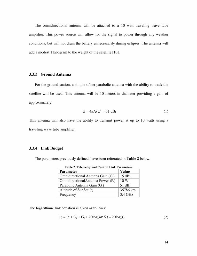
The omnidirectional antenna will be attached to a 10 watt traveling wave tube
amplifier. This power source will allow for the signal to power through any weather
conditions, but will not drain the battery unnecessarily during eclipses. The antenna will
add a modest 1 kilogram to the weight of the satellite [10].
3.3.3 Ground Antenna
For the ground station, a simple offset parabolic antenna with the ability to track the
satellite will be used. This antenna will be 10 meters in diameter providing a gain of
approximately:
G = 4πA/ λ2 = 51 dBi (1)
This antenna will also have the ability to transmit power at up to 10 watts using a
traveling wave tube amplifier.
3.3.4 Link Budget
The parameters previously defined, have been reiterated in Table 2 below.
Table 2. Telemetry and Control Link Parameters
Parameter Value Omnidirectional Antenna Gain (Gt) 15 dBi
OmnidirectionalAntenna Power (Pt) 10 W
Parabolic Antenna Gain (Gr) 51 dBi
Altitude of SunSat (r) 35786 km
Frequency 3.4 GHz
The logarithmic link equation is given as follows:
Pr = Pt + Gr + Gt + 20log(4π /λ) – 20log(r) (2)

15
The last two values represent the losses due to atmospheric attenuation and distance,
respectively. Substituting in the values from Table 2, results in a received power of -117
dBi. This is a best case scenario and does not reflect many of the additional losses that the
signal may incur (i.e. antenna efficiency, amplifier efficiency, or inclement weather).
However, the signal is strong enough such that the link will still be maintained even with
a 50% decrease in signal strength.
3.4 Power Transmission Link
The success of a space-based solar power design is mainly dependant on the ability to
transmit power from space back to Earth. Specifically this transmission link is expected
to be as efficient as possible so that a large percentage of the energy harvested can be
recovered on Earth. With this in mind, it was determined that the rectenna would attempt
to harvest approximately 84% of the transmitted power.
3.4.1 Transmitter Dish Array
One of the key features of the transmitter dish needed to be its ability to minimize
side lobe levels so as to prevent any unwanted radiating on the ground. In order to do
this, it was necessary to create a transmitter dish that is made up of an array of smaller
dishes. The aperture illumination across these dishes can then be tapered in such a way
that minimizes side lobes. This can be done by using a 10dB Gaussian taper across the
array as discussed in a directional magnetron study conducted by NASA and JPL. This

16
means that the power density on the edges of the array would be 1/10 that of the center of
the array [11].
In order to balance the goals of maximizing antenna gain and minimizing rectenna
size, the transmitter dish array was designed to be 500 meters in diameter. Although this
seems large, the array will be folded up for transport and will not be deployed until the
satellite has been properly injected into its final orbit. This will allow the transmitter dish
to easily fan out in space, where it will be less affected by gravity and thereby require less
support. Nonetheless, this large amount of metal will add a significant 1,600,000 kg to
the total weight.
3.4.2 Rectenna
Once the energy is transmitted to the Earth, it is the job of the rectenna to convert the
RF energy back into DC power. When determining the type of rectenna to use, efficiency
was given the highest priority.
The technique chosen for the rectenna is one developed by Suh and Chang [16]. Suh
and Chang developed a method for converting RF to DC at 5.8 GHz with 82.7%
efficiency (as well as 84.4% for 2.45GHz). The design is based off the use of a printed
dipole antenna that is attached to a series of filters that block the re-radiation of higher
order harmonics. After passing through the filters, the signal is then directed through a
Schotky diode, capacitor and load-matched resistor where it is rectified into DC power
[16]. A diagram of the rectenna design can be seen in Figure 8 below.

17
Figure 8. Rectenna design by Suh and Chang [16]
In order to maximize the amount of energy harvested from the rectenna site, these
smaller rectennas will be placed in a large circular array. The most efficient size for the
larger array to harvest approximately the entire main lobe of energy is governed by the
equation:
Dr*Dt = 2.44*λ*r (3)
Solving this equation for Dr, results in a value of approximately 9 kilometers.
3.4.3 Link Budget
The previously discussed parameters regarding the Power transmission link have been
reiterated in Table 3 below.

18
Table 3. Parameters For Power Transmission Link
Parameter Value Transmitter Antenna Efficiency (ηt) 90%
Main Lobe Efficiency (ηL) 84%
Transmitter Antenna Power (Pt) 10 GW
Magnetron Efficiency (ηm) 86%
Rectenna Harvest Efficiency (ηh) 50%
Rectenna Efficiency (ηr) 82.7%
Frequency 5.8 GHz
Using these values in the equation below one can determine that the approximate end-to-
end efficiency:
Pr = 10log(Pt *ηm*ηL*ηt*ηh*ηr) (4)
For this equation the path loss is already included in the main lobe efficiency. Therefore,
the end-to-end efficiency calculates to be approximately 47%. This means that on a clear
day a total of 4.7 GW of power will be delivered to each ground station.

19
4 Design Approach and Details
4.1 Space Hardening
There will be many steps in the process to space hardening the satellites before
sending them into space. These steps will help discover any areas of the satellite that need
to be redesigned or tweaked in order to ensure a successful launch.
The first step in space hardening will be to protect any sensitive areas of the satellite.
This includes reflectors and solar panels that will be exposed to debris that is flying
around in orbit. Protection will include extra layers of clear glass for the solar panels and
possibly a clear film covering for the sun reflectors. The satellite will also need to be
protected from radiation, of which it is likely to be exposed to in space. Radiation testing
will determine where and to what extent shielding will need to be applied to the satellite.
The hardening process will also include extensive lifespan testing in order to
determine the expected lifetime of each part. From the outcome of these tests, the number
of spares and level of redundancy for each part will be determined. The amount of
redundancy will be based on a 20 year lifetime of the SunSats. Although this seems long,
it is well within reach given the minimum station keeping required and the low amount of
debris encountered in GEO orbit.
In addition, vibration testing will be carried out. This testing will take place on an
extra satellite that will be built for the sole purpose of testing. The satellite will be

20
exposed to high levels of vibrations simulating those felt during launch. The outcome of
this test will shed light on the areas that need to be reinforced or to which vibration
dampening material needs to be applied.
Lastly, the satellite will need to be subjected to the same large temperature
fluctuations that will be experienced in orbit. This will help to determine where heaters
will need to be added throughout the body of the spacecraft as well as which parts will
need to be shielded or possibly passively or actively cooled.
4.2 Potential Impacts
Although there are a large number of benefits to space-based solar power, there are
also some unknowns. These unknowns include the potential impact of transmitting large
amounts of energy on the atmosphere and animal/plant life. Furthermore, using
microwave frequencies similar to those already used by electronics may cause unwanted
interference.
4.2.1 Environmental
Much research has been done on the environmental impact of wireless transmissions.
Transmitting power wirelessly could potentially have negative effects on both the
atmosphere and animal/plant life.

21
Atmospheric effects of high power radio transmissions have been poorly studied in
the past. However, it is generally agreed that some amount of ionosphere level heating
will occur [4]. Nonetheless, the radiation from the beam will be of low enough energy
that it will be non-ionizing. In other words, the beam will be incapable of stripping an
electron from a molecule, the main cause of mutations [2].
In regards to humans, the Occupational Safety and Health Administration (OSHA)
has deemed that the acceptable level of consistent radio frequency exposure in the 10
MHz to 100 GHz range is 10mW/cm2 [3]. The power density at the center of the array
will greatly exceed this limit. However, the power density will taper off exponentially
when moving away from the center. To mitigate any possible side effects of the high
radiation levels, workers on the rectenna will be required to wear protective suits and a
monitored security fence that is well labeled will be constructed a minimum of 500
meters from the perimeter of the rectenna.
This power density would exceed the OSHA standard for aircraft as well. Therefore,
a no-fly zone would need to be established around the beam in order to avoid any
incident exposure. Since satellites are already well protected from radiation given their
environmental conditions, the addition of space solar power should not have any effect on
them. However, it may interfere with communication if the satellite is flying through the
power transmission beam and as such will need to be taken into consideration.

22
4.2.2 Existing Electronics
A major concern of broadcasting at microwave frequencies is interference with
wireless devices currently using the same spectrum. According to NASA studies
conducted in relation to the 1980 space-based solar power design, electronics may be
affected up to 100 km from the rectenna. However, strategic use of terrain and sparsely
populated areas for rectenna locations can help to diminish these issues [17].
4.3 Outages
Although all attempts will be made to ensure minimal down time, some outages will
unavoidable. These outages will be both natural and unnatural in nature.
The most common and uncontrollable outages will be due to eclipses. Between
February 28 and April 11, and between September 2 and October 14, roughly 21 days
either side of the equinoxes, the satellites will go into a solar eclipse every day. The
eclipses will gradually get longer until a maximum of approximately 70 minutes. The
eclipses will then gradually get shorter until they are gone [28]. Routine maintenance will
be scheduled within these windows to minimize downtime.
Another major outage concern and unknown is inclement weather. Although it is
highly unlikely that the weather will stop all incoming power, it is likely that the weather
will attenuate the signal strength. The location of the earth station will be the sole factor
in determining how often the power supply will be degraded or potentially interrupted.

23
Given these possible outages it is still expected that the satellites will operate at full
capacity for 99% of the time.
4.4 Assembly
Due to the sheer size of the satellites multiple launches will be needed to get all of the
parts into orbit. Once these parts are on orbit they will need to be assembled. This is more
cost efficient and easily done in low earth orbit (LEO). Therefore, before the vehicles are
moved into GEO orbit they will be assembled in LEO.

24
5 Timeline
The timeline for the project has been determined as described in Table 4 below.
Table 4. Timeline for Space-Based Solar Power Design
'12 '13 '14 '15 '16 '17 '18 '19 '20 '21 '22 '23 '24 '25 '26 '27 '28
Phase 1
R&D
Space Hardening
Launch #1 Assembly in LEO
Transfer to GEO
On-orbit Testing
Launch #2&3
Assembly in LEO
Transfer to GEO
Launch #4&5
Assembly in LEO
Transfer to GEO
Launch #6-8
Assembly in LEO
Transfer to GEO
Phase 2 Launch #9-16
Assembly in LEO
Transfer to GEO
25
6 Budget and Cost Analysis
6.1 SunSat
Final development and manufacturing of the SunSat still needs to be accomplished.
However, assumptions have been developed regarding the costs of each satellite. This
assumption works out to approximately $8 billion per satellite including parts, labor,
materials, and assembly on orbit. Multiplying this by the eight satellites needed plus an
extra satellite for testing, results in a total phase 1 SunSat cost of $72 billion.
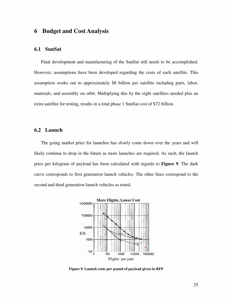
6.2 Launch
The going market price for launches has slowly come down over the years and will
likely continue to drop in the future as more launches are required. As such, the launch
price per kilogram of payload has been calculated with regards to Figure 9. The dark
curve corresponds to first generation launch vehicles. The other lines correspond to the
second and third generation launch vehicles as noted.
Figure 9. Launch costs per pound of payload given in RFP

26
It has been assumed that the second generation launch vehicle will come online in 2016,
five years after the initial program launch. At this point the cost will be approximately
222$/kg to a Hohmann GEO transfer orbit. Table 5 below summarizes the mass of the
satellite.
Table 5. Breakdown of SunSat Mass by Subsystem
Subsystem Mass (Kg) Solar Array 595,238
Reflector Array 2,000
Transmitter Dish 1,600,000
Additional Amount 100%
Total 4,394,476
Given the total mass of each satellite, the launch cost for one calculates to be
$975,573,672. This value increases to $7,804,589,376 when the eight satellites launched
in phase one are taken into account. It should again be noted here that the sheer size of
these satellites will require multiple launches per satellite.
6.3 Ground Command and Monitoring
As with all power production facilities, people will need to monitor the system and
make corrections when need be. For the first phase, it was assumed that five teams of
eight employees would be needed, including eight extra specialists and managers. Four
teams would work on a rotating shift schedule and one team would act as backup for the
others, but would carry on typical daily work schedules when not needed. The total costs
for this are broken down in Table 6 below.
Table 6. Employee Costs
SubLevel Value Number of Operators 40
Pay 35$/hr
Yearly Cost $2,912,000
Total Costs for Phase 1 Life (20 yrs) $58,240,000

27
6.4 Cost Summary
The total cost of the project as well as each major part of the system can be seen in
Table 7 below.
Table 7. Total Costs of Space-Based Solar Power System
SubSystem Cost ($)
SunSats 27,000,000,000
Launches 7,804,589,376
Employees 58,240,000
Total 25,921,069,376
Given the total cost and the 20 year expected lifetime of the satellites, the 99% working
time, and the expected delivery of 4.7 GW, the cost per kWh for phase one satellites over
their lifetime will be $0.013. This figure is quite low but assumes no significant failures
or interruptions are encountered. However, if the initial funds can be accrued, the design
has been justified over the long term.

28
7 References
1. Price, Steve. "Beam It Down, Scotty!" NASA Science. NASA, 23 Mar. 2001. 15 Nov.
2011. <http://science1.nasa.gov/science-news/science-at-nasa/2001/ast23mar_1/>.
2. Logan, James. Safety of Space-Based Solar Power. Tech. Space Energy, Feb. 2009.
Dec. 2011. <http://spaceenergy.com/i/pdf/safety_paper.pdf>.
3. Occupational Safety and Health Standards, Occupational Safety and Health
Administration § 1910.97 (1996).
4. Robinson, T., T. Yeoman, and R. Dhillon. Environmental Impact of High Power
Density Microwave Beams on Different Atmospheric Layers. Tech. no.
18156/04/NL/MV. Leicester, UK: Radio and Space Plasma Physics Group, 2004.
5. "Satellites, Geo-stationary Orbits and Solar Eclipses." IPS Radio and Space Services.
Australian Government. 10 Nov. 2011.
<http://www.ips.gov.au/Category/Educational/SatelliteEclipse.pdf>.
6. United States of America. NASA. Battery Selection Practice for Aerospace Power
Systems. NASA. <http://engineer.jpl.nasa.gov/practices/1221.pdf>.
7. "Spectrum Dashboard." FCC.gov. FCC. 5 Dec. 2011.
<http://reboot.fcc.gov/spectrumdashboard/resultSpectrumBands.seam?conversationId
=17844>.
8. "2D 16-State Error Correction Coding." IDirect.net. IDirect. 2 Dec. 2011.
<http://idirect.net/~/media/Files/Tech%20Briefs/2D%2016State_final.ashx>.
9. "NSA Suite B Cryptography." NSA.gov. NSA. 5 Nov. 2011.
<http://www.nsa.gov/ia/programs/suiteb_cryptography/>.

29
10. "WiFi Antenna | High Gain 802.11 Omni Wireless Antenna." RadioLabs - Radio,
Wireless and Beyond -. RadioLabs. 2 Dec. 2011.
<http://www.radiolabs.com/products/antennas/2.4gig/high-gain-wifi-antenna.php>.
"50ST1G18." Amplifiers.com. 15 Nov. 2011.
<http://www.amplifiers.com/post/50ST1G18.pdf>.
11. Dickinson, R. "Magnetron Directional Amplifier Space Solar Power Beamer Concept
Design."JPL.NASA.gov. NASA, 4 May 2000. 13 Dec. 2011. <http://trs-
new.jpl.nasa.gov/dspace/bitstream/2014/15070/1/00-1077.pdf>.
12. "Magnetron Operation." The Magnetron. GSU. 5 Dec. 2011.
<http://hyperphysics.phy-astr.gsu.edu/hbase/waves/magnetron.html>.
13. "Accelerator : Klystron Is a Microwave Generator (SLAC VVC)." SLAC Public
Website Server. Stanford. 10 Dec. 2011.
<http://www2.slac.stanford.edu/vvc/accelerators/klystron.html>.
14. Buenas, A., and G. Faillon. "A High Power Long Pulse High Efficiency Multi Beam
Klystron."Cern.ch. CERN. 26 Nov. 2011.
<http://mdk2001.web.cern.ch/mdk2001/Proceedings/Session12/beunas.pdf>.
15. "Hohmann Transfer Orbit & Total Travel Time." Polaris Project. Iowa State
University. 2 Dec. 2011.
<http://www.polaris.iastate.edu/EveningStar/Unit6/unit6_sub2.htm>.
16. Suh, Y., and K. Chang. "A High-efficiency Dual-frequency Rectenna for 2.45- and
5.8-GHz Wireless Power Transmission." IEEE Transactions on Microwave Theory
and Techniques 50.7 (2002): 1784-789. Web.

30
17. "Some Questions and Answers About the Satellite Power Systems." NSS.gov.
NASA/DOE, Jan. 1980. Web. 2 Dec. 2011.
<http://www.nss.org/settlement/ssp/library/1980DOESPS-
QuestionsAndAnswersAboutSPS.pdf>.