space based instrumentation for future detection of...
TRANSCRIPT
Space Based Instrumentation forFuture Detection of Artificial ULF/ELF/VLF waves
and Their Effects using theCanadian Sponsored
Enhanced Polar Outflow Project (ePOP) Satellite
Paul Bernhardt1, Carl Siefring1, Andrew Yau2, H. Gordon James3
1Naval Research Laboratory, Washington, DC2University of Calgary, Alberta, Canada
3Communication Research Centre, Ottawa, Ontario, Canada
Enhanced Polar Outflow Probe (ePOP) Science Team
A. W. Yau, P. V. Amerl, L. L. Cogger, E. Donovan, D. J. Knudsen, J. S.Murphree, T. S. Trondsen,University of Calgary
P. A. Bernhardt, C.L. Siefring, Naval Research Laboratory
M. Connors, University of Athabasca
A. Hamza, R. Langley, University of New Brunswick
H. Hayakawa, K. Tsuruda, Institute of Space and Astronautical Science
H. G. James, Communications Research Centre
S. Kostov, G. Sofko, University of Saskatchewan
J. Laframboise, York University
J. MacDougall, J. P. St. Maurice, University of Western Ontario
D. D. Wallis, Magnametrics

Enhanced - Polar Outflow Probe (NRL-0101) ConceptExperiment Description• Directly Monitor Polar
Ionosphere andDisturbances with a Suite of8 Space EnvironmentSensors
• Orbit: 350 x 1500 km >70o Inclination
• Satellite Mass: < 100 kg
Goals/Objectives• Monitor Reduction of Trapped Radiation Using HAARP Radio Transmissions.• Develop Understanding of Magnetosphere-Ionosphere (M-I) Coupling on DoD
Systems using Radio Propagation and Satellites• Demonstrate Capability of Forecasting the Plasma Environment in Near-Earth
Space• Identify System Impacts of Ionospheric Ion Acceleration and Outflow• Study Plasma/Atmospheric Outflow and Wave-Particle Interactions

e-POP Science Objectives: Ion Outflow and Acceleration
• Polar wind ions and electrons– Collisional-collisionless transition region dynamics
• Neutral outflow– Ion-neutral charge exchange and geocorona
• Auroral bulk flow– Role of cold O+ plasma in auroral substorm onset
• Topside auroral ion acceleration and heating– Wave particle interaction and propagation– Temporal/spatial relationship with aurora– Small-scale plasma irregularities
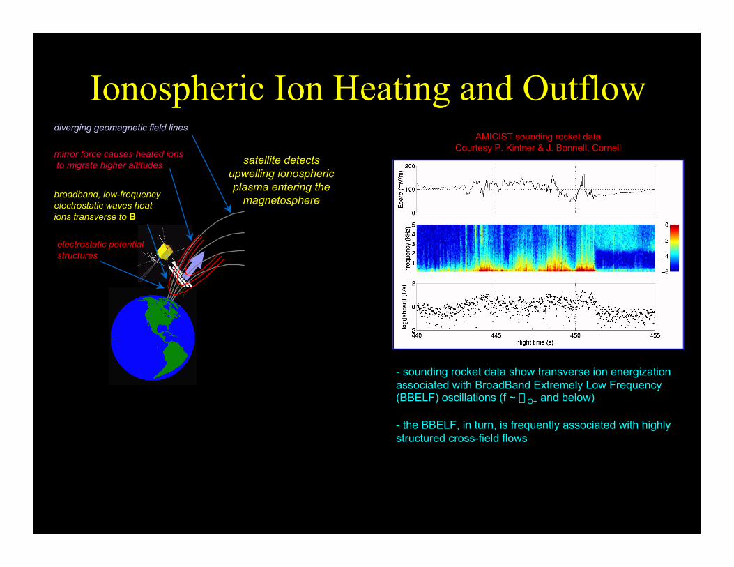
Ionospheric Ion Heating and OutflowAMICIST sounding rocket data
Courtesy P. Kintner & J. Bonnell, Cornell
- sounding rocket data show transverse ion energizationassociated with BroadBand Extremely Low Frequency(BBELF) oscillations (f ~ WO+ and below)
- the BBELF, in turn, is frequently associated with highlystructured cross-field flows
satellite detectsupwelling ionosphericplasma entering the
magnetosphere
diverging geomagnetic field lines
mirror force causes heated ions to migrate higher altitudes
broadband, low-frequencyelectrostatic waves heat ions transverse to B
electrostatic potential structures

e-POP Micro-Satellite:Instrument Payload
– Imaging particle instruments forunprecedented resolution on satellites
• IRM: Imaging rapid ion massspectrometer
• SEI: Suprathermal electron imager• NMS: Neutral mass and velocity
spectrometer
– Auroral imager and wave receiver-transmitter for first micro-satellitemeasurements
• FAI: Fast auroral imager• RRI: Radio receiver instrument• CERTO: Coherent electromagnetic
radio tomography
– Integrated instrument control/datahandling, and science-quality orbit-attitude system data to maximizescience return
• MGF: Magnetometer• GAP: Differential GPS Attitude and
Position System

e-POP Instrument Payload
Instrument Component Volume (cm3) Mass (kg) Power (W) IRM IRM-E 2,880 1.0 9/7 IRM-S 1,178 1.0 IRM-B 707 (1 m boom) 1.5 SEI SEI-E 4,800 1.5 13/9 SEI-S 236 1.0 SEI-B 707 (1 m boom) 2.0 NMS NMS 7,500 7.0 18/18 FAI FAI-E 720 1.0 14/10* FAI-SV 1,178 1.0 FAI-SI 1,178 1.0 RRI RRI ~800 < 5 kg 10*/5* GAP GAP-T 1,977 3.2 15*/8* GAP-A (total) 1,463 2.5 MGF MGF TBD TBD CERTO CERTO-E 263 0.8 5*/5* CERTO-B 1,250 (TBC) 1.0 9.6/6.4 Total 35,800 + TBD 30.5 + TBD
* TBC

e-POP In-situ Measurement Requirements
– Polar wind and suprathermal ions• Composition, density, velocity, temperature (1-40 amu, 0.1-70 eV)
– Atmospheric neutrals• Composition, density, velocity, temperature (1-40 amu, 0.1-2 km/s)
– Ambient and suprathermal electrons• Energy and pitch angle distributions (<200 eV); including photo-
electrons– Convection electric field
• from perpendicular ion drift velocity– Auroral images
• Fast broadband images (10 per sec) and slower monochromaticimages
– Field-aligned current density• from magnetic field perturbations
– Ionospheric irregularities• from differential GPS and CERTO beacon
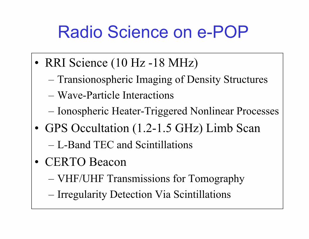
Radio Science on e-POP
• RRI Science (10 Hz -18 MHz)– Transionospheric Imaging of Density Structures
– Wave-Particle Interactions
– Ionospheric Heater-Triggered Nonlinear Processes
• GPS Occultation (1.2-1.5 GHz) Limb Scan– L-Band TEC and Scintillations
• CERTO Beacon– VHF/UHF Transmissions for Tomography
– Irregularity Detection Via Scintillations
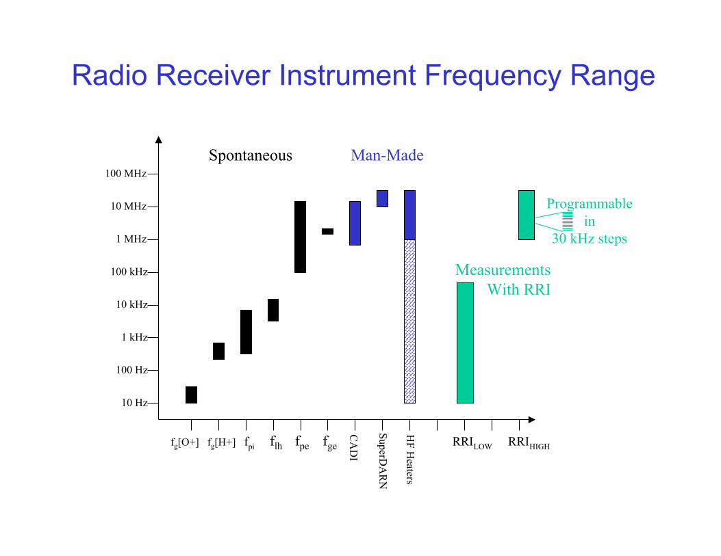
10 Hz
100 Hz
1 kHz
10 kHz
100 kHz
1 MHz
10 MHz
100 MHz
fg[O+] fg[H+] fpi flh fpe fge RRILOW RRIHIGH
CA
DI
SuperDA
RN
HF H
eaters
Spontaneous Man-Made
MeasurementsWith RRI
Programmable in
30 kHz steps
Radio Receiver Instrument Frequency Range

Radio Receiver Instrument
S
S
+
-
+
-
Data andControlSignals
Differenced orDirect Inputs
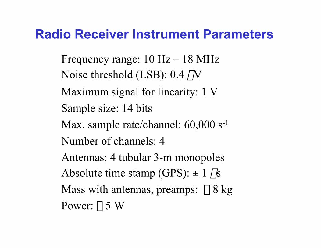
Radio Receiver Instrument Parameters
Frequency range: 10 Hz – 18 MHzNoise threshold (LSB): 0.4 mV
Maximum signal for linearity: 1 V
Sample size: 14 bits
Max. sample rate/channel: 60,000 s-1
Number of channels: 4
Antennas: 4 tubular 3-m monopolesAbsolute time stamp (GPS): ± 1 ms
Mass with antennas, preamps: £ 8 kg
Power: £ 5 W
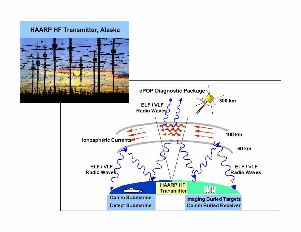
HAARP HF Transmitter, Alaska
ePOP Diagnostic Package
300 km

TRAPPED ENERGETIC PARTICLESTRAPPED ENERGETIC PARTICLESIN THE RADIATION BELTSIN THE RADIATION BELTS

EPOPEPOP MONITORING OF MONITORING OF HAARPHAARP-PRODUCED PRECIPITATION OF-PRODUCED PRECIPITATION OFTRAPPED TRAPPED ENERGETIC PARTICLESENERGETIC PARTICLES IN THE IN THE RADIATION BELTSRADIATION BELTS
ELF/VLFWaves
PrecipitatingElectrons
ReflectedWaves
Pitch AngleScattered Electrons
InteractionRegion
TrappedElectrons
ReflectedWaves
HFInteraction
HAARPTransmitter
Ionosphere
ePOPOrbit
B-Field

HF Heater Radio Induced Aurora (RIA)and Stimulated Electromagnetic Emission (SEE)
Observation Geometry
ePOP
North Distance (km)
West Distance (km)
Alt
itud
e (k
m)
F-Layer Reflection
Level
-200 -100 0 100 200
-200 -1
00
100 200
1
00
200
300
40
0
HF Beam
RIAOpticalCloud
B-Field
SEERadiation
Supra-ThermalElectrons
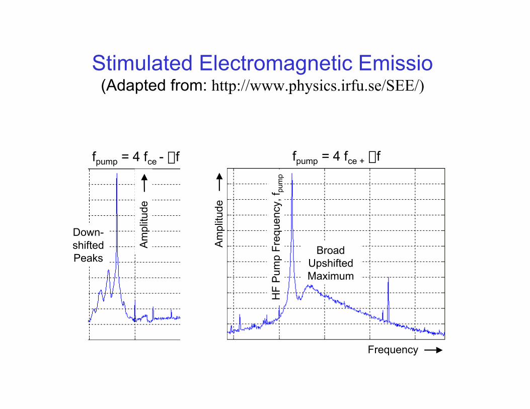
Stimulated Electromagnetic Emissio(Adapted from: http://www.physics.irfu.se/SEE/)
fpump = 4 fce - Df fpump = 4 fce + Df
BroadUpshiftedMaximum
Down-shiftedPeaks
HF
Pum
p F
requ
ency
, fpu
mp
Am
plitu
de
Frequency
Am
plitu
de

05 February 2002, HAARP Alaska, 630.0 nm Excited by 5.8 MHz30 Second Exposures, 37° x 37° Field-of-View
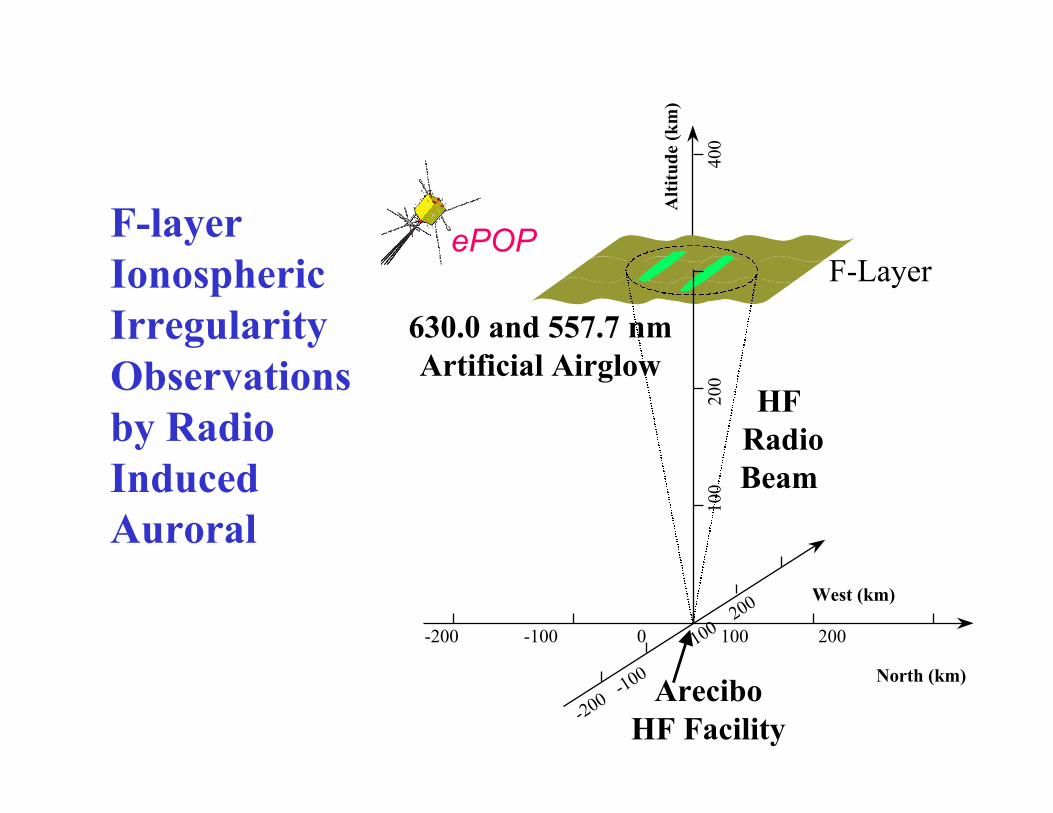
F-layerIonosphericIrregularityObservationsby RadioInducedAuroral
North (km)
West (km)
100
2
00
400
Alt
itud
e (k
m)
F-Layer
-200 -100 0 100 200
-200 -100
100 2
00
HF RadioBeam
630.0 and 557.7 nmArtificial Airglow
AreciboHF Facility
ePOP

17 February 2002, HAARP Alaska, 557.7 nm Excited by 4.8 MHz30 Second Exposures, 18.5° x 18.5° Field-of-View
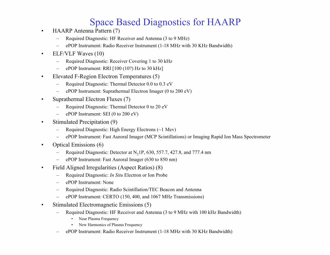
Space Based Diagnostics for HAARP• HAARP Antenna Pattern (7)
– Required Diagnostic: HF Receiver and Antenna (3 to 9 MHz)
– ePOP Instrument: Radio Receiver Instrument (1-18 MHz with 30 KHz Bandwidth)
• ELF/VLF Waves (10)– Required Diagnostic: Receiver Covering 1 to 30 kHz
– ePOP Instrument: RRI [100 (10?) Hz to 30 kHz]
• Elevated F-Region Electron Temperatures (5)– Required Diagnostic: Thermal Detector 0.0 to 0.3 eV
– ePOP Instrument: Suprathermal Electron Imager (0 to 200 eV)
• Suprathermal Electron Fluxes (7)– Required Diagnostic: Thermal Detector 0 to 20 eV
– ePOP Instrument: SEI (0 to 200 eV)
• Stimulated Precipitation (9)– Required Diagnostic: High Energy Electrons (~1 Mev)
– ePOP Instrument: Fast Auroral Imager (MCP Scintillations) or Imaging Rapid Ion Mass Spectrometer
• Optical Emissions (6)– Required Diagnostic: Detector at N21P, 630, 557.7, 427.8, and 777.4 nm
– ePOP Instrument: Fast Auroral Imager (630 to 850 nm)
• Field Aligned Irregularities (Aspect Ratios) (8)– Required Diagnostic: In Situ Electron or Ion Probe
– ePOP Instrument: None
– Required Diagnostic: Radio Scintillation/TEC Beacon and Antenna
– ePOP Instrument: CERTO (150, 400, and 1067 MHz Transmissions)
• Stimulated Electromagnetic Emissions (5)– Required Diagnostic: HF Receiver and Antenna (3 to 9 MHz with 100 kHz Bandwidth)
• Near Plasma Frequency
• New Harmonics of Plasma Frequency
– ePOP Instrument: Radio Receiver Instrument (1-18 MHz with 30 KHz Bandwidth)
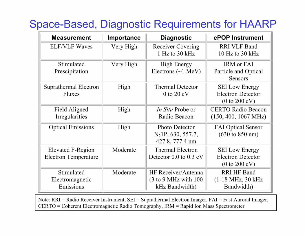
Space-Based, Diagnostic Requirements for HAARPMeasurement Importance Diagnostic ePOP Instrument
ELF/VLF Waves Very High Receiver Covering 1 Hz to 30 kHz
RRI VLF Band 10 Hz to 30 kHz
Stimulated Prescipitation
Very High High Energy Electrons (~1 MeV)
IRM or FAI Particle and Optical
Sensors Suprathermal Electron
Fluxes High Thermal Detector
0 to 20 eV SEI Low Energy Electron Detector
(0 to 200 eV) Field Aligned Irregularities
High In Situ Probe or Radio Beacon
CERTO Radio Beacon (150, 400, 1067 MHz)
Optical Emissions High Photo Detector N21P, 630, 557.7, 427.8, 777.4 nm
FAI Optical Sensor (630 to 850 nm)
Elevated F-Region Electron Temperature
Moderate Thermal Electron Detector 0.0 to 0.3 eV
SEI Low Energy Electron Detector
(0 to 200 eV) Stimulated
Electromagnetic Emissions
Moderate HF Receiver/Antenna (3 to 9 MHz with 100
kHz Bandwidth)
RRI HF Band (1-18 MHz, 30 kHz
Bandwidth)
Note: RRI = Radio Receiver Instrument, SEI = Suprathermal Electron Imager, FAI = Fast Auroral Imager,CERTO = Coherent Electromagnetic Radio Tomography, IRM = Rapid Ion Mass Spectrometer

High LatitudeScintillation
Models• Climatological Models
for Global Scintillations
• Seasonal and SolarCycle Dependencies
• No Capability for Real-Time ScintillationPredictions
– Variable Occurrence
– Unpredictable Intensity
– Complex Dynamics
• Climatological Modelsfor Global Scintillations
• Seasonal and SolarCycle Dependencies
• No Capability for Real-Time ScintillationPredictions
– Variable Occurrence
– Unpredictable Intensity
– Complex Dynamics

In Situ Measurements of O+-Ion Flow area Proxy for F-Region Irregularities that
Produce Radio Wave Scintillations
• Structuring of Polar CapPatches
• High Latitude IonosphericIrregularities– U. of Maryland Simulation
– Ref.: Guzdar et al., 2001
• Plasma Turbulence on WideRange of Scales– Parallel Electric Fields
– Polar Outflow of O+ Ions
– Ion Signature of F-RegionIrregularities
Isosurfaces of the density
Gradient-Drift Instability and Nonlinear Inertial Effect Constant Instability Drive: b = 20,000, n(z) R=Nmax/Nmin=2
t=0 s t=5880 s
Isosurfaces of the density
Gradient-Drift Instability and Nonlinear Inertial Effect Constant Instability Drive: b = 20,000, n(z) R=Nmax/Nmin=2
t=0 s t=5880 s
Altitude
LatitudeLongitude

Enhanced - Polar Outflow Probe (NRL-0101)Radio Wave Propagation and Particle Interactions
HF/VHF Radar
e-POPreceiver
IonosphericIrregularities
ImpactDetermination
• Orbiting e-POPReceiver, HF Radar,and IonosphericIrregularities
• Coordinatedobservation of radarecho propagationwith ground radarfacility
• In-situ observationof scattered HFwaves in the high-latitude ionosphere

e-POP Microsatellite - Project Status
• Mission Development– Enhanced POP (e-POP) selected by CSA and NSERC in 2001/08
for mission (instrument and spacecraft bus) development– NSERC funding for Science Team and CSA funding for
instrument development to start in FY01/02• Instrument Payload
– Original POP instruments (IRM, SEI, NMS): preliminary designin progress; development of engineering model to commenced2002
– FAI and RRI: Concept design & feasibility study completed2001/07, preliminary design commenced 2001/08
– CERTO: Inclusion of instrument on e-POP via US DoD• Spacecraft Bus
– CSA to procure spacecraft bus under separate industrialcontract

Enhanced - Polar Outflow Probe e-POP (NRL-0101)Summary
• The National Security Space Architect (NSSA) Space Weather Architecture Study(1999) identifies ionospheric specification and forecast (including high latitudescintillations and D-region absorption) as a National Security Priority.
• The HAARP/Tether Panel on Military Applications of HAARP (2002) identifiesradiation belt mitigation as a high priority. The ePOP diagnostics package directlyaddresses the generation and detection of ELF/VLF for radiation belt particledepletion using HAARP.
• Scintillation, Scattering and Absorption have a significant operational impact, whichimpact UHF SATCOM, GPS navigation, and Aircraft HF Communications at highlatitudes.
• ePOP provides vital measurements of ionospheric parameters that control thegeneration of scintillation-producing irregularities and radio wave absorption at highlatitudes.