sp2 report on mechanism of calcium aluminate cement (cac
TRANSCRIPT

1
SP2 Report on
Mechanism of Calcium Aluminate Cement (CAC) Corrosion
Based on Accelerated Corrosion Test
Date: 15th August 2012
Author and Chief Investigator: Marjorie Valix

2
TABLE OF CONTENTS
1.0 INTRODUCTION ............................................................................................................... 5
2.0 EXPERIMENTAL .............................................................................................................. 5
2.1 CAC MATERIAL ............................................................................................................... 5 2.2 CORROSION TESTING ....................................................................................................... 6 2.3 MATHEMATICAL MODELS .................................................................................................. 6
2.3.1 Kinetic Models ......................................................................................................... 6 2.3.2 Progress of Corrosion Based on Diffusion Controlled Reaction .............................. 7
3.0 RESULTS .......................................................................................................................... 8
3.1 MECHANISM OF CORROSION ............................................................................................ 8 3.2 PROGRESSION OF CORROSION ...................................................................................... 11 3.3 EFFECT OF ACID TYPE ON CORROSION OF CAC ............................................................. 12 3.4 RELATIVE EFFECT OF ACID AND CONCENTRATION ON CAC CORROSION ........................... 20 3.5 RELATIVE PERFORMANCE OF SEWPERCOAT AND BASF-CAC IN SULPHURIC AND CITRIC ACID .................................................................................................................................... 22 3.6 IMPLICATIONS OF PERFORMANCE OF CAC IN VARIOUS BIOGENIC ACID IN FIELD PERFORMANCE .................................................................................................................... 22 3.7 EFFECT OF TEMPERATURE ............................................................................................. 23

3
Summary This study examined the accelerated corrosion of two types of CAC, Sewpercoat from Kerneos and BASF CAC. Corrosion was conducted to reflect the effect of various biogenic acids that may influence the corrosion of CAC. Our analysis of the sequential growth of the organism revealed the presence of acids generated by fungi and sulphur oxidising bacteria. As such CAC corrosion tests were conducted by immersion in four types of acids, sulphuric, citric, malic and nitric acids. Testing was conducted in concentrations from 1-10(g/ml)% at temperature of 30, 35 and 45°C to reflect the typical condition in Sydney, Melbourne and Perth. The following outcomes were derived from this study:
• The corrosion of CAC in general follows an initial passive period, where the reaction is chemically controlled, followed by a diffusion controlled corrosion.
• CAC corrodes without leaving an ‘ash layer’ as such the rate or progression of
corrosion could be measured directly from thickness loss.
• Increasing the acid concentration in general increased the passive period. This suggests that CAC is an ideal protective coating for a highly corrosive environment.
• The diffusion of the organic acids was found to be an order of magnitude higher than
sulphuric acid. According to the sequential growth of organisms, fungi first metabolises organic acids, followed by the metabolism of sulphuric acid by sulphur oxidising bacteria. This suggests the initial rate of corrosion, if the growth of organism followed the above sequence, would be higher initially, and would decrease with the production of sulphuric acid
• Increasing the acid concentration was found to increase the diffusion of sulphuric acid. However organic acids reached an optimum diffusion coefficient with concentration. After which higher concentration appear to result in lower diffusion coefficient.
• The acids in the CAC installed in Sydney, Melbourne and Perth generally showed the
production of primarily organic acids and either none or minor quantities of sulphuric acid were generated. Data from Sydney suggest this persist for 3 years. This is attributed to the maintenance of alkaline surface in CAC with service. The amount of organic acid generated was highest in Perth followed by Melbourne and then Sydney.
• The implications of these results to the performance of CAC are that CAC may be
better suited in the Perth environment. The higher organic acid generated in Perth would result is longer passive period, and also lower diffusion coefficient. In Melbourne, although the passive period may initially be higher in comparison to Sydney, the acid diffusion would be higher. In Sydney, the passive period would be shorter but lower acid diffusion coefficient.
• Temperature > 30°C was found to overcome the initial passivation of CAC, but in
general the diffusion of both organic and sulphuric acids were reduced with increasing temperature.

4
• The implication of these results would be the better performance of CAC in Perth as a result of the higher temperature environment in comparison to Sydney and Melbourne.

5
1.0 Introduction Calcium aluminate cement (CAC) is principally made up of lime (C or CaO) and alumina (A or Al2O3). CaO-Al2O3 has four to five nearly stoichiometric compounds, which can be called calcium aluminates including (C=CaO and A=Al2O3): C3A, C12A7, CA2 and CA6 and a number of less reactive phases derived from impurities of the raw materials.
On reaction with water, the hydration product of CAC is determined by the temperature of hydration. The rapid hydration reaction leads to a large release of heat during the early stages of hydration. This often heats sections of the hydration products to temperatures up to 70 °C during curing. The reactions that will proceed as a result of these temperatures are shown in equations 1-3 (Scrivener et al., 1999) (H= H2O): 6CA + 10H → 6CAH10 (T<15°C) (1)
↓ 6CA + 60 H → 3C2AH8+ 3AH3+ 27H (70°C <T<15°C) (2)
↓ 6CA + 63 H → 3C3AH6+ 3AH3+ 36H (70°C <T) (3) The most stable phases are C3AH6 and AH3 and the other phases will inevitably lead to these phases at a rate that depends on the temperature and moisture content within the hydrates.
Modelling the service life of CAC will require an insight into the mechanisms that control its corrosion rate in the sewer. The corrosion mechanism of calcium aluminate cement in the sewer was considered by a series of accelerated tests. As demonstrated by previous reports in the sequential growth of the organism, apart from sulphuric acid, other acids, primarily organic acids and carbonic acids may also play a role in corroding this cement based coating. In this study, the corrosion of CAC was considered in sulphuric acid, malic, citric and nitric acids.
The rate of corrosion was examined by monitoring the mass of CAC, loss of thickness and from the percentage of dissolved metals (Al, Fe and Ca). These data were assessed by fitting the experimental data to known diffusion and chemical controlled kinetic models based on the shrinking core model.
2.0 Experimental
2.1 CAC Material The CAC used in these tests were obtained from two manufacturers, Sewpercoat from Kerneos and CAC from BASF. Analysis was conducted using PHILIPS PW2400 XRF with Rh end-window tube. The sample was first dried at 105°C prior to analysis. The chemical compositions of both CAC are shown in Table 1.

6
Table 1. Chemical composition of CAC from Kerneos and BASF
Chemical Constituents
Kerneos (CAC) -
Sewpercoat
BASF
Al2O3 41.3 35.04 CaO 37.4 32.92 Cr2O3 0.13
Fe2O3 9.54 10.06
K2O 0.3 0.12
MnO 0.12 0.05
NiO 0.137
SiO2 6.97 6.02
TiO2 1.93 1.72
V2O5 0.05
ZrO2 0.14
Na2O
0.15
MgO
0.37
P2O5
0.08
SO3
< 0.01
LOI 1.03 13.15
TOTAL 99.047 99.68
2.2 Corrosion Testing Cylindrical cores (50 mm diameter and 10 cm length) of hydrated calcium aluminate cement were manufactured using the manufacturer’s instruction. These were immersed in various acids. The acids included sulphuric acid, malic, citric and nitric acids in 1.0-20wt% concentration and were kept at temperatures from 30, 35 and 45°C.
2.3 Mathematical Models
2.3.1 Kinetic Models
The aim of any kinetic modeling is to identify the rate determining factor. This is achieved by deriving and solving a steady state diffusion migration transport equations for all soluble reacting and non reacting species in the system in conjunction with the appropriate boundary conditions for a given rate controlling regime. The resulting expressions were simplified and are shown in Equations (1) – (4) (Abdel-Aal, 2000, Levenspiel, 1972, Olanipekun, 2000, Sohn and Wadsworth, 1979). 𝑎 = 𝑘!𝑡 (4)

7
1 − 1 − 𝑎!! = 𝑘!𝑡 (5)
1 −23𝑎 − (1 − 𝑎)
!! = 𝑘!𝑡 (6)
1 − (1 − 𝑎)!! + 𝐵 1 −
23𝑎 − (1 − 𝑎)
!! = 𝑘!𝑡 (7)
Where a= fraction of metals dissolved with time t; k0, k1, k2= overall rate constants (min-1); k3= mixed model rate constant (min-1 mol-1); B= k1/k2
Equation (4) expresses bulk diffusion (film diffusion control) which can be overcome by increasing the turbulence around the coating (Levenspiel, 1972, Sohn and Wadsworth, 1979). Equation (5) assumes the rate determining step of the leaching rate is the chemical reaction on the surface of the mineral, Equation (6) assumes the rate-determining step is diffusion through the product layer (pore diffusion control), and Equation (7) assumes the rate determining step of the leaching rate is the combination of chemical control and diffusion control. The dissolution of specific metals (e.g. Al3+ from CAC) obtained from a batch data can be fitted into the established shrinking core models expressed above. The fit of the data to the models determines the rate determining step for the reaction and thus the factor which controls and determines the rate of the coating dissolution.
2.3.2 Progress of Corrosion Based on Diffusion Controlled Reaction The progress of corrosion under diffusion controlled reaction could be approximated by the moving boundary reaction diffusion model. The shrinking core model has been used to describe the rates of corrosion of concrete where the rate of movement of the boundary is considered slower than the transport rates of the acids. Because of the slow movement of the boundary, the mass transport could be considered to be always at steady state. In case of sulphate ion attack, for example, the sulphate ion is considered to migrate inwards through the corrosion product into the boundary with uncorroded material. At the interface the sulphate ions will react with the hydration products of CAC, consisting of CAH10, C2AH8, C3AH6 and AH3) to produce Al(OH)3, and dissolved Al and Ca sulphate species. The mass transport is assumed to be always at steady state and is then used to estimate the rate of progression of the corrosion interface through the concrete. The corrosion reactions can be simplistically expressed as follow:
C3AH6 +6H+ → 3Ca2+ + 2Al(OH)3(s) +6H2O (8) Alumina hydrate is usually stable at pH from 3.5-4.0. Below pH 4.0, the hydrate will dissolve to form monomeric Al3+ (Scrivener et. al., 1999): 2Al(OH)3(s) + 6H+ → 2Al3+ + 6H2O (9) The flux of sulphate ions is given as:

8
𝑁 = −𝐷!
!!!
(10) The rate of progression of the corrosion interface is then the rate of sulphate mass transport divided by the concentration of the Al2O3 and CaO in CAC. !"!"= − !
!!= !!!!
!!! (11)
The solution to this equation is given as: 𝑥 = (!!!!!
!!𝑡)!/! = 𝑘𝑡!/! (12)
Where k = !!!!!!!
Ca = concentration of Al2O3 and CaO in CAC solid (moles/cm3)
Co = concentration of the sulphate or corresponding acid anion in the bulk solution (moles/cm3)
X = depth of corrosion (cm)
Di = acid anion diffusion coefficient (cm2/s)
t = time (s)
3.0 Results
3.1 Mechanism of Corrosion The depth of acid permeation through CAC and concrete are shown in Figure 1. As shown in concrete, as the acid permeates a layer of partially corroded concrete remains. However in CAC, this partially corroded layer is not apparent. This suggests that in monitoring the progress of corrosion through CAC, loss of thickness would give appropriate measure of the rate of corrosion.
CAC Concrete
Figure 1. Depth of Acid Permeation through CAC and concrete

9
The depth of corrosion as measured from the thickness loss, changes in mass measured as the saturated surface dry weight of CAC and percentage metal dissolution from Sewpercoat in 5% sulphuric acid in Figures 2-4. These results demonstrate two distinct regions of corrosion. From 0 to 20 days, it appears CAC is passivated or demonstrate a slow corrosion and this is followed by faster corrosion rate.
Figure 2. Depth of corrosion with time of Sewpercoat in 5% H2SO4.
Figure 3. Change in mass of Sewpercoat in 5% H2SO4.
0
0.02
0.04
0.06
0.08
0.1
0.12
0.14
0 10 20 30 40 50
xo (m
m)
t(days)
Sewpercoat, 5 % H2SO4
215
220
225
230
235
240
245
250
0 10 20 30 40 50
SSD (sa
turated surfa
ce dry), (g)
t(days)
Sewpercoat, 5 % H2SO4

10
Figure 4. Metal dissolution from Sewpercoat in 5% H2SO4.
The mechanism of corrosion was assessed by fitting the dissolved metal data to the kinetic models in equations 4-7.
The percentage dissolve Al over the period of 0 to 20 days were found to fit the chemical controlled model (see Figure 5) with R2 of 0.99 and the data from 20 days to 42 days were found the fit the diffusion controlled model with R2 of 0.98 (see Figure 6). This suggests CAC corrosion showed an initial chemical resistance to acid attack. However with time this reaction became faster and the mass transport through the CAC porosity became the rate determining step.
Figure 5. Fitting chemical controlled model to the early phase of CAC corrosion in 5% H2SO4.
0
0.0002
0.0004
0.0006
0.0008
0.001
0.0012
0 5 10 15 20 25
1-‐(1-‐a)(1/3)
Time (days)
Al
0
0.2
0.4
0.6
0.8
1
1.2
0 10 20 30 40 50
% Dissolved M
etals
Time (days)
Al
Fe
Ca

11
Figure 6. Fitting chemical controlled model to the early phase of CAC corrosion in 5% H2SO4.
3.2 Progression of Corrosion The progression of corrosion was examined by fitting the depth of corrosion or thickness loss from day 20 to 24 (see Figure 2) to equation 12 in Figure 7.
Figure 7. Fitting the depth of corrosion data of CAC corroded in 5% H2SO4 to the progression model, a) all the depth of corrosion data and b) data under diffusion control.
-‐5E-‐07
0
0.0000005
0.000001
0.0000015
0.000002
0.0000025
0.000003
0.0000035
0.000004
0 10 20 30 40 50
1-‐2/3 a-‐(1-‐a)(2/3)
Time (days)
Al
0
0.02
0.04
0.06
0.08
0.1
0.12
0.14
0 0.05 0.1 0.15 0.2 0.25 0.3 0.35 0.4
xo (m
m)
t(year)^0.5
Sewpercoat, 5 % H2SO4
12
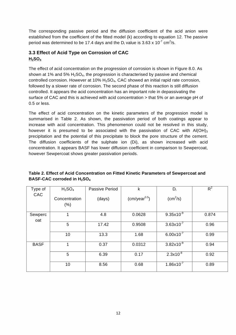
The corresponding passive period and the diffusion coefficient of the acid anion were established from the coefficient of the fitted model (k) according to equation 12. The passive period was determined to be 17.4 days and the Di value is 3.63 x 10⁻⁷ cm2/s.
3.3 Effect of Acid Type on Corrosion of CAC H2SO4
The effect of acid concentration on the progression of corrosion is shown in Figure 8.0. As shown at 1% and 5% H2SO4, the progression is characterised by passive and chemical controlled corrosion. However at 10% H2SO4, CAC showed an initial rapid rate corrosion, followed by a slower rate of corrosion. The second phase of this reaction is still diffusion controlled. It appears the acid concentration has an important role in depassivating the surface of CAC and this is achieved with acid concentration > that 5% or an average pH of 0.5 or less.
The effect of acid concentration on the kinetic parameters of the progression model is summarised in Table 2. As shown, the passivation period of both coatings appear to increase with acid concentration. This phenomenon could not be resolved in this study, however it is presumed to be associated with the passivation of CAC with Al(OH)3 precipitation and the potential of this precipitate to block the pore structure of the cement. The diffusion coefficients of the sulphate ion (Di), as shown increased with acid concentration. It appears BASF has lower diffusion coefficient in comparison to Sewpercoat, however Sewpercoat shows greater passivation periods.
Table 2. Effect of Acid Concentration on Fitted Kinetic Parameters of Sewpercoat and BASF-CAC corroded in H2SO4
Type of CAC
H2SO4
Concentration (%)
Passive Period
(days)
k
(cm/year0.5)
Di
(cm2/s)
R2
Sewpercoat
1 4.8 0.0628 9.35x10⁻⁹ 0.874
5 17.42 0.9508 3.63x10⁻⁷ 0.96
10 13.3 1.68 6.00x10⁻⁷ 0.99
BASF 1 0.37 0.0312 3.82x10⁻⁹ 0.94
5 6.39 0.17 2.3x10⁻⁸ 0.92
10 8.56 0.68 1.86x10⁻⁷ 0.89

13
1% H2SO4 5% H2SO4 10% H2SO4
Figure 8. Effect of Acid Concentration in the Progression of Corrosion in Sewpercoat in H2SO4 and solution pH with time.
0
0.02
0.04
0.06
0.08
0.1
0.12
0.14
0 0.05 0.1 0.15 0.2 0.25 0.3 0.35 0.4
xo (cm)
t(days)0.5
Sewpercoat, 5 % H2SO4
0
0.05
0.1
0.15
0.2
0.25
0 0.05 0.1 0.15 0.2 0.25 0.3 0.35
xo (cm)
t(years)^0.5
Sewpercoat, 10 % H2SO4
0
0.5
1
1.5
2
2.5
3
3.5
4
0 0.05 0.1 0.15 0.2 0.25 0.3 0.35 0.4
Solution
pH
Time (years)0.5
Sewpercoat, 1% H2SO4
0
0.5
1
1.5
2
2.5
3
3.5
4
0 0.05 0.1 0.15 0.2 0.25 0.3 0.35 0.4
Solution
pH
Time (years)0.5
Sewpercoat, 5% H2SO4
-‐1
-‐0.5
0
0.5
1
1.5
2
2.5
3
3.5
4
0 0.05 0.1 0.15 0.2 0.25 0.3 0.35
Solution
pH
Time (years)0.5
Sewpercoat, 10% H2SO4

14
Citric Acid
The effect of citric acid concentration on the progression of corrosion is shown in Figure 9. At 1% Citric acid the pH varied around 4.5. Although Al ions form Al(OH)3 at pH 4.0, it appears that in presence of citric acid CAC continued to dissolve as shown in the progression of corrosion. However the samples appear to undergo a series of passivation.
Corrosion in 5 and 10% citric acids were also characterised by the two regions of passivation and corrosion under diffusion control. The corresponding kinetic parameters in Table 3 show that in Sewpercoat, increasing the acid concentration led to higher sulphate diffusion and passive region. The effect was opposite for the BASF-CAC samples. Overall it appears the performance of Sewperscoat is better in citric acid than BASF, which showed order of magnitude higher diffusion coefficients.
Table 3. Effect of Acid Concentration on Fitted Kinetic Parameters of Sewpercoat and BASF-CAC corroded in Citric Acid.
Type of CAC
Citric
Concentration (%)
Passive Period
(days)
k
(cm/year0.5)
Di
(cm2/s)
R2
Sewpercoat
1 0 NA NA NA
5 3.54 0.867 7.62x10⁻⁷ 0.92
10 5.49 2.09 2.16x10⁻⁶ 0.96
BASF 1 NA NA NA NA
5 9.27 3.21 1.74x10⁻⁵ 0.92
10 2.4 3.36 9.8x10⁻⁶ 0.986

15
1% Citric Acid 5% Citric Acid 10% Citric Acid
Figure 9. Effect of Acid Concentration in the Progression of Corrosion in Sewpercoat in Citric Acid and solution pH with time.
0
0.01
0.02
0.03
0.04
0.05
0.06
0.07
0 0.01 0.02 0.03 0.04 0.05 0.06
xo (m
m)
t(years)^0.5
Sewpercoat, 1 % Citric
0
0.05
0.1
0.15
0.2
0.25
0 0.05 0.1 0.15 0.2 0.25 0.3 0.35 0.4
xo (m
m)
t(years)^0.5
Sewpercoat, 5 % Citric
0
0.05
0.1
0.15
0.2
0.25
0.3
0.35
0.4
0.45
0.5
0 0.05 0.1 0.15 0.2 0.25 0.3 0.35
xo (m
m)
t(years)^0.5
Sewpercoat, 10 % Citric
0
1
2
3
4
5
6
7
0 0.01 0.02 0.03 0.04 0.05 0.06
Solution pH
t (years)0.5
Sewpercoat, 1 % Citric
0
1
2
3
4
5
6
7
0 0.01 0.02 0.03 0.04 0.05 0.06 0.07
Solution pH
t (years)0.5
Sewpercoat, 5 % Citric
0
1
2
3
4
5
6
7
0 0.01 0.02 0.03 0.04 0.05 0.06
Solution pH
t (years)0.5
Sewpercoat, 10 % Citric

16
Malic Acid
The increase in passivation with increasing acid concentration in Sewpercoat is also apparent in malic acid (see Figure 10). However the reverse is found in BASF-CAC. Table 4 shows an optimum diffusion coefficient is found at 5% malic acid in both Sewpercoat and BASF- CAC.
Table 4. Effect of Acid Concentration on Fitted Kinetic Parameters of Sewpercoat and BASF-CAC corroded in Malic Acid
Type of CAC
Malic
Concentration (%)
Passive Period
(days)
k
(cm/year0.5)
Di
(cm2/s)
R2
Sewpercoat
1 0 0.1865 1.13x10⁻⁷ 0.95
5 9.7 1.368 1.12x10⁻⁶ 0.8
10 11.86 0.6335 1.31x10⁻⁷ 0.71
BASF 1 7.6 0.3304 5.94x10⁻⁷ 0.96
5 0.1 0.7783 6.63x10⁻⁷ 0.77
10 0 0.2629 3.74x10⁻⁸ 0.95

17
1% Malic Acid 5% Malic Acid 10% Malic Acid
Figure 10. Effect of Acid Concentration in the Progression of Corrosion in Sewpercoat in Malic Acid and solution pH with time.
0
0.01
0.02
0.03
0.04
0.05
0.06
0.07
0.08
0 0.05 0.1 0.15 0.2 0.25 0.3 0.35
xo (m
m)
t(years)^0.5
Sewpercoat, 1 % Malic Acid
0
0.05
0.1
0.15
0.2
0.25
0 0.05 0.1 0.15 0.2 0.25 0.3 0.35
xo (m
m)
t(years)^0.5
Sewpercoat, 5 % Malic Acid
0
0.02
0.04
0.06
0.08
0.1
0.12
0 0.05 0.1 0.15 0.2 0.25 0.3 0.35
xo (m
m)
t(years)^0.5
Sewpercoat, 10 % Malic Acid
012345678910
0 0.05 0.1 0.15 0.2 0.25 0.3 0.35
Solution pH
t (years)0.5
Sewpercoat, 1 % Malic Acid
0
1
2
3
4
5
6
7
0 0.05 0.1 0.15 0.2 0.25 0.3 0.35
Solution pH
t (years)0.5
Sewpercoat, 10 % Malic Acid

18
Nitric Acid
Figure 11 shows an optimum passivation at 5% nitric in both CAC samples. The effect of increasing acid concentration in increasing the diffusion coefficient is apparent in Table 5.
Table 5. Effect of Acid Concentration on Fitted Kinetic Parameters of Sewpercoat and BASF-CAC corroded in Nitric Acid
Type of CAC
Nitric Acid
Concentration (%)
Passive Period
(days)
k
(cm/year0.5)
Di
(cm2/s)
R2
Sewpercoat
1 0 0.0993 1.42x10⁻⁸ 0.94
5 3.6 0.9145 5.97x10⁻⁷ 0.96
10 0.93 2.098 1.47x10⁻⁶ 0.99
BASF 1 0 0.1669 7.18x01-8 0.9
5 2.46 1.0276 1.4x10⁻⁶ 0.98
10 1.466 1.466 1.43x10⁻⁶ 0.99

19
1% Nitric Acid 5% Nitric Acid 10% Nitric Acid
Figure 11. Effect of Acid Concentration in the Progression of Corrosion in Sewpercoat in Nitric Acid and solution pH with time.
0
0.005
0.01
0.015
0.02
0.025
0.03
0.035
0 0.05 0.1 0.15 0.2 0.25 0.3 0.35
xo (m
m)
t(years)^0.5
Sewpercoat, 1 % Nitric Acid
0
0.02
0.04
0.06
0.08
0.1
0.12
0.14
0.16
0.18
0.2
0 0.05 0.1 0.15 0.2 0.25 0.3
xo (m
m)
t(years)^0.5
Sewpercoat, 5 % Nitric Acid
0
0.1
0.2
0.3
0.4
0.5
0.6
0 0.05 0.1 0.15 0.2 0.25 0.3 0.35
xo (m
m)
t(years)^0.5
Sewpercoat, 10 % Nitric Acid
0
1
2
3
4
5
6
7
0 0.05 0.1 0.15 0.2 0.25 0.3 0.35
Solution pH
t (years)0.5
Sewpercoat, 1 % Nitric Acid
0
1
2
3
4
5
6
7
0 0.05 0.1 0.15 0.2 0.25 0.3
Solution pH
t (years)0.5
Sewpercoat, 5 % Nitric Acid
0
1
2
3
4
5
6
7
0 0.05 0.1 0.15 0.2 0.25 0.3 0.35
Solution pH
t (years)0.5
Sewpercoat, 10 % Nitric Acid

20
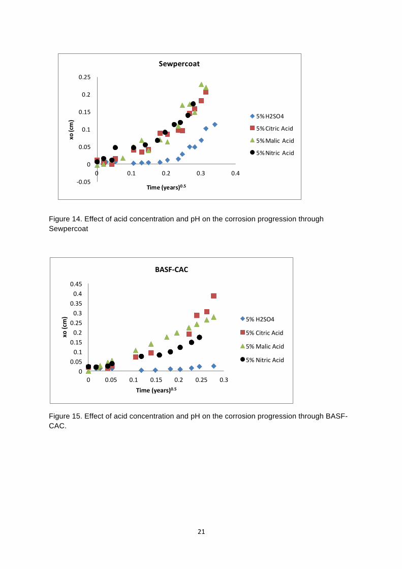
3.4 Relative effect of acid and concentration on CAC corrosion The overall effect of acid type and acid concentration on the diffusion of acid ions in Sewpercoat and BASF-CAC is shown in Figures 12 and 13 respectively. The diffusion coefficients are plotted as a function of acid concentration and acid pH. As shown the diffusion coefficient organic acids, in particular citric acid is an order of magnitude higher in comparison the mineral acids, sulphuric and nitric acids. This effect is more prominent in the BASF- CAC sample. This is attributed to the ability of the organic acids to form stable complexes rather than Al(OH)3 precipitate.
It is also apparent that as the organic acid concentration increases, the diffusion coefficient decreases. This is shown in the malic acid results in Sewpercoat and in citric acid in BASF-CAC.
The effect of acid type and concentration is also reflected from the progression of corrosion in Sewpercoat and BASF-CAC in Figures 14 and 15.
Figure 12. Effect of acid concentration and pH on the acid ion diffusion through Sewpercoat
Figure 13. Effect of acid concentration and pH on the acid ion diffusion through BASF-CAC.
0.00E+00
5.00E-‐07
1.00E-‐06
1.50E-‐06
2.00E-‐06
2.50E-‐06
0 2 4 6 8 10 12
Di(cm
2 /s)
Acid Concentration (g/ml)%
Sewpercoat
H2SO4
Citric Acid
Malic Acid
Nitric Acid
0.00E+00
5.00E-‐07
1.00E-‐06
1.50E-‐06
2.00E-‐06
2.50E-‐06
0 1 2 3 4 5Di(cm
2 /s)
Solution pH
Sewpercoat
H2SO4
Citric Acid
Malic Acid
Nitric Acid
0.00E+00
2.00E-‐06
4.00E-‐06
6.00E-‐06
8.00E-‐06
1.00E-‐05
1.20E-‐05
1.40E-‐05
1.60E-‐05
1.80E-‐05
2.00E-‐05
0 2 4 6 8 10 12
Di(cm
2 /s)
Acid Concentration (g/ml)%
BASF
H2SO4
Citric Acid
Malic Acid
Nitric Acid
0.00E+00
2.00E-‐06
4.00E-‐06
6.00E-‐06
8.00E-‐06
1.00E-‐05
1.20E-‐05
1.40E-‐05
1.60E-‐05
1.80E-‐05
2.00E-‐05
-‐1 0 1 2 3 4 5
Di(cm
2 /s)
Acid Concentration (g/ml)%
BASF
H2SO4
Citric Acid
Malic Acid
Nitric Acid
21
Figure 14. Effect of acid concentration and pH on the corrosion progression through Sewpercoat
Figure 15. Effect of acid concentration and pH on the corrosion progression through BASF-CAC.
0 0.05 0.1 0.15 0.2 0.25 0.3 0.35 0.4 0.45
0 0.05 0.1 0.15 0.2 0.25 0.3
xo (cm)
Time (years)0.5
BASF-‐CAC
5% H2SO4
5% Citric Acid
5% Malic Acid
5% Nitric Acid
-‐0.05
0
0.05
0.1
0.15
0.2
0.25
0 0.1 0.2 0.3 0.4
xo (cm)
Time (years)0.5
Sewpercoat
5% H2SO4
5% Citric Acid
5% Malic Acid
5% Nitric Acid
22
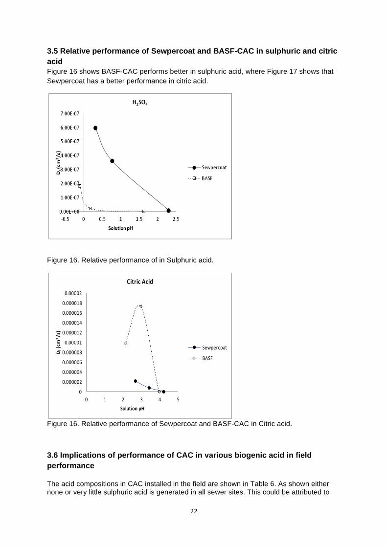
3.5 Relative performance of Sewpercoat and BASF-CAC in sulphuric and citric acid Figure 16 shows BASF-CAC performs better in sulphuric acid, where Figure 17 shows that Sewpercoat has a better performance in citric acid.
Figure 16. Relative performance of in Sulphuric acid.
Figure 16. Relative performance of Sewpercoat and BASF-CAC in Citric acid.
3.6 Implications of performance of CAC in various biogenic acid in field performance The acid compositions in CAC installed in the field are shown in Table 6. As shown either none or very little sulphuric acid is generated in all sewer sites. This could be attributed to
0
0.000002
0.000004
0.000006
0.000008
0.00001
0.000012
0.000014
0.000016
0.000018
0.00002
0 1 2 3 4 5
Di(cm
2/s)
Solution pH
Citric Acid
Sewpercoat
BASF

23
maintenance of an alkaline surface pH throughout its service. The organic acids generated do not appear to change significantly with time. The relative quantity generated is highest in Perth, followed by Melbourne then Sydney.
• These results suggest the corrosion of CAC would principally occur as a result of organic acid attack.
• From Figure 16, it appears Sewpercoat may provide a better performance than BASF-CAC.
• Another feature to note is the greater passive period that would be experienced in Perth and Melbourne compared to Sydney. As shown in Figure 9-11, increasing the acid concentration appear to result in greater passive period.
• Once the diffusion of the acid occurs, the rate of corrosion will increase with an increase with organic acid concentration. However as shown in Figures 12 and 13, there appears to be an optimum concentration when diffusion coefficient will increase. Higher organic acid concentrations promote slower acid diffusion. This suggest that the diffusion is likely to be high in Melbourne, but lower in Perth because of the higher organic acids generated in these sewers.
3.7 Effect of Temperature The effects of temperature on the progress of corrosion in CAC immersed in 10% sulphuric and citric acids are shown in Figures 17 and 18. A summary of the kinetic parameters is given in Tables 7 and 8. The relative effect of temperature is both acids are shown in Figure 19. Two notable features of increasing the temperature is the loss of the passive period and the general reduction in biogenic acid diffusion through CAC. The implications of these results suggest the better performance of CAC in Perth, where the temperature is higher in comparison to both Melbourne and Sydney.
Figure 17. Effect of temperature on corrosion progression of CAC in 10% H2SO4.

24
Table 6. Biogenic acids in CAC installed in the sewers.
Acid Concentration (mg/g substrate)
City Sewer Location
Nominal Period
(months) Period (days) Lactic Succinic Pyruvic Ketoglutaric Malic Citric Fumaric Sulphuric Total Organic
Sydney South Barrel Tidal 6 0.0 0.0 0.0 2.3 16.6 1.04 0.0 19.9
Sydney South Barrel Crown 6 0.0 0.0 0.0 0.3 27.8 7.24 3.3 38.6
Sydney South Barrel Crown 12 13.3 0.0 0.0 0.3 15.3 0.98 1.7 31.6
Sydney South Barrel Tidal 12 0.0 0.0 0.0 1.1 15.5 0.37 0.4 17.4
Sydney Crown 36 1095 0.0 0.0 0.0 0.1 15.6 0.00 25.0 0.2 40.7 Sydney Tidal 36 1095 0.0 0.0 0.0 0.1 27.2 0.00 1.2 28.5
Melbourne WTS Crown 6 0.0 0.0 0.0 0.8 7.6 0.64 0.4 9.5 Melbourne WTS Tidal 6 0.0 0.0 0.0 0.0 1.1 0.00 296.7 297.7 Melbourne STS Crown 12 0.0 0.0 0.0 1.9 149.7 6.28 42.7 200.6 Melbourne WTS Crown 12 0.0 0.0 0.0 0.1 1.0 0.00 357.5 358.6 Melbourne WTS Tidal 12 0.0 0.0 0.0 0.0 1.1 0.05 330.3 331.5
Perth Bibra Lakes Crown 6 0.0 0.0 0.0 0.0 9.3 0.00 335.7 0.1 345.0
Perth Perth MS Crown 6 0.0 0.0 0.0 0.1 10.0 0.00 1478.1 1488.2 Perth Perth MS Tidal 6 0.0 0.0 0.0 0.1 11.2 0.00 319.4 330.7
Perth Bibra Lakes Tidal 6 0.0 0.0 0.0 0.0 11.9 0.00 481.1 0.2 493.0

25
Table 7. Effect of Temperature on Fitted Kinetic Parameters of Sewpercoat in 10% H2SO4 Type of
CAC Temperature °C Passive Period
(days)
k
(cm/year0.5)
Di
(cm2/s)
R2
Sewpercoat
30 13.3 1.68 6.00x10⁻⁷ 0.99
35 0 0.5295 6.46x10⁻⁸ 0.95
45 0 0.1511 5.26x10⁻⁹ 0.91
Figure 18. Effect of temperature on corrosion progression of CAC in 10% Citric Acid.
Table 8. Effect of Temperature on Fitted Kinetic Parameters of Sewpercoat in 10% Citric Acid.
Type of CAC
Temperature °C Passive Period
(days)
k
(cm/year0.5)
Di
(cm2/s)
R2
Sewpercoat
30 5.49 2.09 2.16x10⁻⁶ 0.96
35 0 2.05 9.64x10⁻⁷ 0.927
45 0 0.98 5.2x10⁻⁷ 0.93
0
0.05
0.1
0.15
0.2
0.25
0.3
0.35
0.4
0.45
0.5
0 0.1 0.2 0.3 0.4
xo (m
m)
t(years)^0.5
Sewpercoat, 10 % Citric Acid
30oC
35oC
45oC

26
Figure 19. Relative effect of temperature on Di of sulphate and citrate anion in Sewpercoat.