sp non-clogging self-priming sewage pump operation manual
TRANSCRIPT

SP Non-clogging Self-priming Sewage Pump
Operation Manual
Hangzhou Nanfang Special Pump Industry Co., Ltd.
State High-tech Enterprise
Hangzhou Nanfang Special Pump Industry Co.,LtdAdd:Renhe Town Yuhang District,Hangzhou,zhejiangTel:+86-571-86397810; +86-571-86397838Fax:+86-571-86397809P.C:311107E-mail:[email protected]://www.nanfang-pump.com E081101
Standard:Q/HNB***( Non-clogging Self-priming Sewage Pump)
Read this manual carefully before install, start the pump.
I INTRODUCTION
Thank You for purchasing CNP pump. Read this manual carefully to learn how to
safely install and operate your pump. Failure to do so could result in personal injury or
damage to the pump.
This operation manual is designed to help you achieve the expected performance and
longest life from the CNP pump.
SP Non-clogging self priming sewage pump is our latest developed product, and is su
-itable for the treatment project of municipal sewage and industrial sewage as well as stage
treatment and concentrated treatment system of various sewages. It's known as King of
Self-priming Sewage Pump and the most ideal new-generation sewage product.
1 Application
Non flammable and non-explosive liquid;
Rain water and common sewage;
Municipal drainage project ,construction site, drainage station of people's air defense
system;
Industrial sewage of light industry, paper mill, textile, food processing plant, chemical
industry, electric utility, deep mines, etc;
Sewage discharge in the residential area;
Sewage and deposit of water purifying system;
Tanning industry, sewage of slaughter house ,fish breeding in the river and pond;
Wine and sugar industry;
Discharge sewage of not strongly corrosive but seriously polluted.
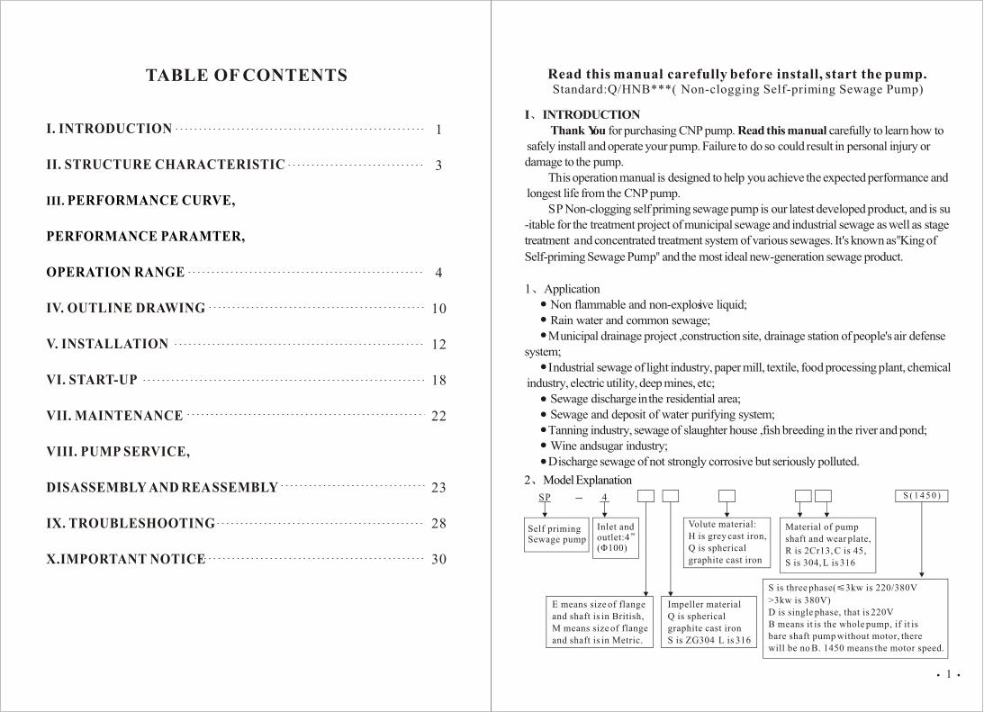
Self priming Sewage pump
Inlet and outlet:4(Ö100)
E means size of flange
and shaft is in British,
M means size of flange
and shaft is in Metric.
Impeller material
Q is spherical
graphite cast iron
S is ZG304 L is 316
Volute material:
H is grey cast iron,
Q is spherical
graphite cast iron
Material of pump
shaft and wear plate,
R is 2Cr13, C is 45,
S is 304, L is 316
S is three phase( 3kw is 220/380V
>3kw is 380V)
D is single phase, that is 220V
B means it is the whole pump, if it is
bare shaft pump without motor, there
will be no B. 1450 means the motor speed.
2 Model Explanation
1
TABLE OF CONTENTS
I. INTRODUCTION
II. STRUCTURE CHARACTERISTIC
IV. OUTLINE DRAWING
V. INSTALLATION
VI. START-UP
VII. MAINTENANCE
VIII. PUMP SERVICE,
DISASSEMBLY AND REASSEMBLY
IX. TROUBLESHOOTING
X.IMPORTANT NOTICE
III. PERFORMANCE CURVE,
PERFORMANCE PARAMTER,
OPERATION RANGE
1
3
4
10
12
18
22
23
28
30

3 Operating condition3 3
Liquid temperature: 0 -40 , medium density 1.2 10 kg/m pH5-9;
Volume ratio of solids in the medium 2%;
Diameter of maximum grain:SP-2 38mm SP-3 63mm; SP-4/SP-6 76mm
Ambient temperature: 40
Altitude:Max.1,000m;
Max. working pressure: see Performance Curve;
Max. Suction head: see Performance Table
II STRUCTURE CHARACTERISTIC
1 Features
Stable performance, reliable operation;
The motors clockwise rotation from drive; The pump shall be installed on
the pedestal . axial suction and radial discharge;
Back-pull-out construction :Convenient for maintenance and troubleshoot
-ing. Daily maintenance can be performed rapidly by common head tools, sav
-ing time and labor;
Semi-open impeller structure and non-clogging design: Strong passing
capacity.
Convenient usage: The pump can be mounted high and dry at floor level.
With only the suction line down in the liquid (the pump shall be filled with
water for first start).
Quick suction, high suction head, see performance table.
2 Pump structure (Figures 1)
SP Non-clogging
Self-priming Sewage Pump
1 SUCTION FLANGE
2 FLAP VALVE
3 INFUSION COVER
4 DISCHARGE FLANGE
5 END COVER
6 WEAR PLATE
7 IMPELLER
8 VOLUTE
9 SEAL BASE
10 MECHANICAL SEAL
11 O-RING
12 SHAFT
13 BEARING BODY
14 BEARING COVER
15 END COVER HANDLE
16 INFUSION CLAMP
17 SPANNER
18 INFUSION CLAMP HANDLE
19 IMPELLER BOLT WASHER
20 FLAP VALVE RIVET
21 FLAP PLATE
22 PIN
23 BEARING COVER GASKET
24 ADJUSTING SCREW M12 25
25 SUCTION FLANGE GASKET
26 O-RING
27 O-RING
28 SAFE VALVE
29 DISCHANGE FLANGE GASKET
30 INFUSION GASKET
31 LOCK WASHER
32 BOLT
33 LOCK WASHER
34 BOLT
35 BOLT
36 FRONT BEARING
37 LOCK WASHER
38 BOLT
39 BOLT
40 BACK BEARING
41 LIP SEAL B40-62-8
42 PIPE PLUG
43 PIPE PLUG
44 CASING DRAINAGE PLUG
45 BOLT
46 BOLT
47 PIPE PLUG
48 BOLT
49 LOCK WASHER 6
50 RETAINER 40-5
51 STUD
52 BOLT
53 LIFTING BOLT
54 KEYCB 28
55 SIGHT GUAGE
56 ADJUSTING SHIMS
57 BOLT
Figure 1 SP-080701
32
It is single-stage single suction cantilever pump. It is mainly composed of
volute, impeller, wear plate, seal base, bearing body, etc;
The main wet part is made of cast iron parts;
Pump shaft is supported by two high precision rolling bearing, bearing
cabinet and seal cabinet is lubricated by thin oil;
Shaft seal is single face mechanical seal, wearing part is WC/WC. O ring
is made by NBR.
Pump and pipelines is connected by flanges which comply to GB/T standard.
III PERFORMANCE CURVE, PERFORMANCE PARAMTER,
OPERATION RANGE
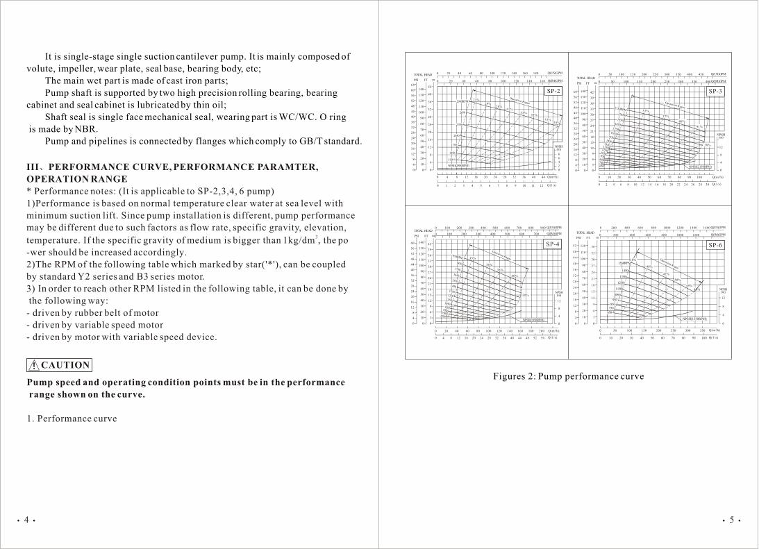
* Performance notes: (It is applicable to SP-2,3,4, 6 pump)
1)Performance is based on normal temperature clear water at sea level with
minimum suction lift. Since pump installation is different, pump performance
may be different due to such factors as flow rate, specific gravity, elevation,3
temperature. If the specific gravity of medium is bigger than 1kg/dm , the po
-wer should be increased accordingly.
2)The RPM of the following table which marked by star('*'), can be coupled
by standard Y2 series and B3 series motor.
3) In order to reach other RPM listed in the following table, it can be done by
the following way:
- driven by rubber belt of motor
- driven by variable speed motor
- driven by motor with variable speed device.
CAUTION
Pump speed and operating condition points must be in the performance
range shown on the curve.
1. Performance curve
0 20 40 60 80 100 120 140 160 180
0 20 40 60 80 100 120 140 160
64
60
56
52
48
44
40
36
32
28
24
20
16
12
8
4
0
140
130
120
110
100
90
80
70
60
50
40
30
20
10
0
44
40
36
32
28
24
20
16
12
8
4
0
0 1 2 3 4 5 6 7 8 9 10 11 12
0 4 8 12 16 20 24 28 32 36 40 44
8
6
4
2
0
NPSH(m)
Q(m /h)
Q(1/s)
3
Q(IM)GPM
Q(US)GPM
2900RPM
NPSH(2900RPM)
2650
2350
2050
1750
1450
1150
TOTAL HEAD
PSI FT m
21%
24%28%
31%33%
35%
37%35%
SP-2 60
56
52
48
44
40
36
32
28
24
20
16
12
8
4
0
140
130
120
110
100
90
80
70
60
50
40
30
20
10
0
42
39
36
33
30
27
24
21
18
15
12
9
6
3
0
0 50 100 150 200 250 300 350 400 450
0 50 100 150 200 250 300 350 400
0 10 20 30 40 50 60 70 80 90 100
0 2 4 6 8 10 12 14 16 18 20 22 24 26 28 30
12
8
4
0
NPSH(m)
Q(1/s)
Q(IM)GPM
Q(US)GPM
3Q(m /h)
TOTAL HEAD
PSI FT m
33%
37%
40%
41%
38%
2150RPM
2050
19501850
17501650
650
11501250
1350
1450
1550
NPSH(2150RPM)
SP-3
1050950
750
850
750650
850950
1050
1850
1750
1650
1250
1350
1450
1550
1150
1950RPM
NPSH(1950RPM)
35%
36%
38%
40%
39%
60
56
52
48
44
40
36
32
28
24
20
16
12
8
4
0
140
130
120
110
100
90
80
70
60
50
40
30
20
10
0
42
39
36
33
30
27
24
21
18
15
12
9
6
3
0
0 100 200 300 400 500 600 700 800 900
0 100 200 300 400 500 600 700
0 20 40 60 80 100 120 140 160 180 200 Q(m /h)3
0 4 8 16 20 24 28 32 36 40 44 52 5612
12
8
4
0
Q(IM)GPM
Q(US)GPM
NPSH(m)
Q(1/s)
TOTAL HEAD
PSI FT m
48
SP-4
1150
950
850
750
650
NPSH(1550RPM)
40%
47%
50%
49%
48%
52
48
44
40
36
32
28
24
20
16
12
8
4
0
120
110
100
90
80
70
60
50
40
30
20
10
0
36
33
30
27
24
21
18
15
12
9
6
3
0
0 50 100 150 200 250 300 350
0 10 20 30 40 50 60 70 80 90 100
0 200 400 600 800 1000 1200 1400 1600
0 200 400 600 800 1000 1200 Q(IM)GPM
Q(US)GPM
NPSH(m)
12
8
4
0
Q(1/s)
3Q(m /h)
TOTAL HEAD
PSI FT m
SP-6
1050
1250
1350
1450
38%1550RPM
Figures 2: Pump performance curve
54
Operation Ragne Operation Ragne
Operation Ragne
Operation Ragne

2. Performance Table 2. Performance Table
SP-2
1150
1450*
1750
2050
2350
2650
2900*
15
20
25
28
32
35
40
4.2
5.6
6.9
7.8
8.9
9.7
11.1
4.0
6.5
9.5
13.5
18.0
23.0
27.0
0.75
1.5
2.2
4.0
5.5
7.5
9.2
1
2
3
5.5
7.5
10
12.5
50(2') 38
5.5
6.5
6.5
6.5
6.5
6.5
6.5
1/sm /h3 m kW HP mm mm m
SP-3
650
750*
850
950*
1050
1150
1250
1350
1450*
1550
1650
1750
1850
1950
2050
2150
25
30
32.5
40
42.5
45
50
52.5
55
60
65
70
72.5
75
80
85
6.9
8.3
9.0
11.1
11.8
12.5
13.9
14.6
15.3
16.7
18.1
19.4
20.1
20.8
22.2
23.6
2
3
4
4.5
5.5
7
8
10
11.5
12.5
14.5
16
18
20
22.5
24.5
0.75
1.5
1.5
1.5
2.2
4.
4.
5.5
5.5
7.5
11
11
15
15
15
18.5
1
2
2
2
3
5.5
5.5
7.5
7.5
10
15
15
20
20
20
25
80(3') 63
1.5
1.8
2.4
3.0
4.0
4.9
5.5
5.8
6.4
6.4
6.7
6.7
7.6
7.6
7.6
7.6
Model RPMQ H Motor
Max.Solids
1/s3 m HP mm mm m
Inlet&Outlet
Model RPMQ H Motor
Max.Solids
Inlet&Outlet
Max.Suction Model RPM
Q H MotorMax.
SolidsInlet&Outlet
Max.Suction
Model RPMQ H Motor
Max.Solids
Inlet&Outlet
Max.Suction
Max.Suction
kWm /h
1/sm /h3 m kW HP mm mm m
SP-6
650
750*
850
950*
1050
1150
1250
1350
1450*
1550
100
125
150
160
180
200
220
230
250
280
27.8
34.7
41.7
44.4
50.0
55.6
61.1
63.9
69.4
77.8
3.5
4.5
5.5
7.5
9.0
10.0
12.5
15
17
18
2.2
4
5.5
7.5
11
15
18.5
22
30
30
3
5.5
7.5
10
15
20
25
30
40
40
150(6') 76
2.4
2.7
3.6
4.2
5.5
6.4
6.4
6.7
7.0
7.6
1/sm /h3 m kW HP mm mm m
SP-4
650
750*
850
950*
1050
1150
1250
1350
1450*
1550
1650
1750
1850
1950
40
45
53
60
65
72
80
85
100
110
115
120
130
135
11.1
12.5
14.7
16.7
18.1
20.0
22.2
23.6
27.8
30.6
31.9
33.3
36.1
37.5
3
4
5
6
7.5
9
10.5
12.5
13.5
15.5
18
20
22.5
25
1.5
1.5
2.2
3
4
5.5
7.5
11
11
15
15
18.5
22
30
2
2
3
4
5.5
7.5
10
15
15
20
20
25
30
40
100(4') 76
1.5
2.4
4.9
5.8
6.7
7.3
7.6
7.6
7.6
7.6
7.6
7.6
7.6
7.6
76

RPM 20 32 48 64 80 96 112 128 144 160
SP-4
650
750*
850
950*
1050
1150
1250
1350
1450*
1550
1650
1750
1850
1950
H(m)
3.8 3.3
4.5
6.0
7.5
9.7
11.9
14.2
16.7
2.6
3.7
5.3
6.5
8.7
10.8
13.2
15.7
18.0
20.9
24.3
27.6
31.0
34.5
3.0
4.5
5.7
7.8
9.9
12.0
14.3
16.5
19.8
22.9
26.2
29.8
33.4
3.5
5.0
6.8
8.8
10.8
13.1
15.5
18.3
21.1
24.4
27.7
31.5
5.9
7.6
9.5
11.8
14.0
16.9
19.8
22.9
26.1
29.4
8.4
10.5
12.5
15.4
18.1
21.3
24.4
27.7
11.5
13.8
16.3
19.3
22.5
25.7
12.6
15.0
17.5
20.5
23.5
16.2
18.7
21.7
(m /h)3
Q
RPM 50 80 120 150 180 210 240 270 300
SP-6
650
750*
850
950*
1050
1150
1250
1350
1450*
1550
H(m)
5.0 4.2
6.0
8.0
11.0
13.0
16.0
3.1
4.7
7.0
9.5
11.0
14.0
17.0
20.5
24
28
3.6
5.5
7.5
10.0
12.8
15.5
19.0
22.0
26.0
6.8
9.0
11.2
14
17.5
21
24.5
7.5
10.0
12.7
15.5
19.0
22.7
8.0
10.5
14.0
17.0
20.5
12.0
15.0
18.5
13.0
16.5
(m /h)3
Q
RPMm /h3
Q10 12.5 15 17.5 20 25 30 35 40 45
SP-2
1150
1450*
1750
2050
2350
2650
2900*
H(m)
5.1
8.4
12.6
17.9
4.7
8.1
12.2
17.2
23.2
30.1
4.0
7.6
11.8
16.7
22.5
29.2
35.6
3.8
7.3
11.3
16.1
21.8
28.4
34.5
3.5
6.5
10.8
15.5
21.2
27.6
33.7
5.8
9.5
14.5
19.9
26.2
32.1
8.5
13.2
18.6
24.8
30.4
11.6
17.2
23.0
29.0
15.3
21.6
27.0
19.4
25.3
RPM(m /h)3
Q10 20 30 40 50 60 70 80 90 100
SP-3
650
750*
850
950*
1050
1150
1250
1350
1450*
1550
1650
1750
1850
1950
2050
2150
H(m)
2.9
3.9
5.2
6.4
7.9
9.7
11.3
2.5
3.5
4.7
6.0
7.4
9.0
10.7
12.6
14.7
16.8
19.3
2.0
3.0
3.9
5.2
6.7
8.3
10.0
11.9
14.0
16.1
18.5
20.9
23.5
26.2
29.0
32.1
2.3
3.4
4.5
5.9
7.4
9.1
11.0
12.9
15.1
17.4
19.7
22.5
25.3
28.0
31.0
3.8
5.0
6.5
8.0
10.0
12.0
14.0
16.2
18.7
21.2
24.1
26.8
29.7
4.3
5.6
7.1
9.0
10.8
12.5
15.0
17.5
20.0
22.7
25.3
28.2
6.2
7.7
9.6
11.7
13.6
16.0
18.4
21.0
24.0
26.8
8.3
10.4
12.3
14.5
16.9
19.6
22.5
25.1
9.1
11.1
13.2
15.3
17.9
20.5
23.4
11.8
14.0
16.4
18.9
21.7
3. Operating Range 3. Operating Range
Model
Model
Model
Model
98

IV OUTLINE DRAWING
Table3 Pumpdimensions
Figures 3 Pump Dimensions
1 Pump Dimensions
I t e m
Dimension
of Inlet
&
Outlet
Flange
Installation
Dimension
Profile
Dimension
PN
DN
D
D1
D2
n- d1
SP-2 SP-3 SP-4 SP-6
PN0.6MPa
Class150
PN1.0MPa
Class150
H2(mm)
A(mm)
A1(mm)
B(mm)
B1(mm)
L2(mm)
d2(mm)
H3(mm)
L3(mm)
318
308
281
163.2
54
274.8
14
151.5
104
431.8
377
328
228.6
76.2
285
18
190.5
102
495.3
428
373
279.4
110
326
18
222.2
127
574.3
580
527
279.4
77.8
294
18
257.2
127
d
h b 1
38
50
2"
140
6"
110
4.75"
90
3.6"
4- 14
4- 3/4"
80
3"
190
7.5"
150
6"
128
5"
4- 19
4- 3/4"
100
4"
220
9"
180
7.5"
158
6.2"
8- 19
8- 3/4"
150
6"
285
11"
240
9.5"
214
8.34"
8- 23
8- 7/8"
10 5 95
.38" .19" 3.74"
10 5 80
.38" .19" 3"
10 5 90
H(mm)
H4(mm)
L(mm)
L4(mm)
E1(mm)
E2(mm)
Wt. (kg/1bs)
552
502
615
233
27.5
70
99/218
697.5
652
712.2
277
15
50
190/419
760
735
813.5
318
13
50
275/606
875
887.7
906.6
411
0
50
438/966
10 5 90
2 Profile & Installation Dimension of Pump Unit With Motor
Figures 4 Installation Dimension of Pump Unit With Motor
Table 4 Installation Dimension of Pump Unit With Motor
SP-3
SP-4
SP-6
750
950
1450
750
950
1450
750
950
1450
Y2-112M-8
8 Poles
Y2-100L-6
6 Poles
Y2-132S-4
4 Poles
Y2-112M-8
8 Poles
Y2-132S-6
6 Poles
Y2-160M-4
4 Poles
Y2-160M-8
8 Poles
Y2-160M-6
6 Poles
Y2-200L-4
4 Poles
330
370
510
542
606.3
710
300.5
332.2
393
761
843
1022
621
614
660
663
702
821
784
784
905
1134
1119
1204
1236
1306
1451
1544
1544
1705
489
471
514
520
545
592
653
653
738
190
180
210
190
210
255
255
255
305
78.5
90.5
58.5
110.2
90.2
62.2
97.2
97.2
57.2
861
854
900
963
1002
1121
1084
1084
1205
380
430
590
785
871
996
120
150
150
ModelSpeed Motor Installation Dimension Profile Dimension
RPM Frame Ad Ld2 H11 H31 H41 K Am Hm HD AD E Ld Ld1
Y2-90L-4
4 Poles
Y2-132-2
2 Poles
306 428 261.5 612 341 662 100SP-2
1450
2900
695
982
1107
422
575
155
210
61.5
19.5
864
*: 1)The base is welded by profiled bar 2)Mounting Type:IMB3
1110
DIN(mm)
ANSI
DIN(mm)
ANSI
DIN(mm)
ANSI
DIN(mm)
ANSI
DIN(mm)
ANSI
DIN(mm)
ANSI
1.5"
DIN(mm)
ANSI
DIN(mm)
ANSI .38" .19" 3.5"

V INSTALLATION
1 Preinstall Inspection
The pump assembly was inspected and tested before shipment from the
factory. Before installation, inspect the pump for damage which may have
occurred during shipment. Check as follows
Inspect the pump for cracks, dents, damaged threads, and other obvious
damage,
Check for and tighten loose attaching hardware. Since gaskets tend to
shrink after drying, check for loose hardware at mating surfaces.
Carefully read all tags, decals, and markings on the pump assembly, and
perform all duties indicated.
Check levels and lubricate as necessary.
If the pump and engine have been stored for more than 12 months, some
of the components or lubricants may have exceeded their maximum shelf life.
These must be inspected or replaced to ensure maximum pump service.
2 Positioning Pump(Figure 5)
Fixed place installation
Pipe should be lower than theliquid level.
By-pass
Sewagehole
By-pass
Suctionpipe
Support
Auto air vent valve
Discharge pipe
Throttling valve and check valve on discharge pipe
SP pump
Installation on a moveable cart
SP pump
Pump outlet Pump driver
Wheel
Figure 5 (Pump installation sketch figure)
Locate the pump in an accessible place as close as practical to the liquid being pumped. Level mounting is essential for proper operation. The pump may have to be supported or shimmed to provide for level operation or to eliminate vibration, or shimmed by rubber cushion when necessary. If the pump has been mounted on a moveable base, make certain the base is stationary by setting the brake and blocking the wheels before attempting to operate the pump. Do not position the pump and engine more than 15 off horizontal for continu-ous operation. If installed in a flooded suction application where the liquid is supplied to the pump under pressure. Since the pressure supplied to the pump is critical to perfor-mance and safety, be sure to limit the incoming pressure to 50% of the maximum permissible operating pressure as shown on the pump performance curve. Clearance When positioning the pump, allow a minimum clearance of 500 mm in front of the end cover to permit removal of the cover and easy access to the pump interior. Suction And Discharge Piping Pump performance is adversely effected by increased suction lift, discharge elevation, and friction losses. See the performance curve and notes on Page E-1 to be sure your overall application allows pump to operate within the safe operation range. Materials Either pipe or hose maybe used for suction and discharge lines; however, the materials must be compatible with the liquid being pumped. If hose is used in suction lines, it must be the rigid-wall, reinforced type to prevent collapse under suction. Using piping couplings in suction lines is not recommended. 3 Line Configuration
Keep suction and discharge lines as straight as possible to minimize friction losses. make minimum use of elbows and fittings, which substantially increase friction loss. If elbows are necessary, use the long-radius type to minimize frictionloss. Connections to Pump Before tightening a connecting flange, align it exactly with the pump port. Never pull a pipe line into place by tightening the flange bolts and/or couplings. Lines near the pump must be independently supported to avoid strain on the pump which could cause excessive vibration, decreased bearing life, and increased shaft and seal wear. If hose-type lines are used, they should have adequate support to secure them when filled with liquid and under pressure. Gauges Most pumps are drilled and tapped for installing discharge pressure and vacuum suction gauges. If these gauges are desired for pumps that are not tapped, drill and tap the suction and discharge lines not less than 18 inches (460 mm) from the suction
1312
Discharge flange

and discharge ports and install the lines. Installation closer to the pump may result in erratic readings. Suction Lines To avoid air pockets which could affect pump priming, the suction line must be as short and direct as possible. When operation involves a suction lift, the linemust always slope upward to the pump from the source of the liquid being pumped; if the line slopes down to the pump at any point along the suction run, air pockets will be created.
Error Right
Figures 6
Suction lines should be the same size as the pump inlet. If reducers are used insuction lines, they should be the eccentric type, and should be installed with the flat part of the reducers uppermost to avoid creating air pockets. Valves are not normally used in suction lines, but if a valve is used, install it with the stem horizontal to avoid air pockets. Strainers If a strainer is furnished with the pump, be certain to use it; any spherical solidswhich pass through a strainer furnished with the pump will also pass through the pump itself. Sealing Since even a slight leak will affect priming, head, and capacity, especially when operating with a high suction lift, all connections in the suction line should be sealed with pipe dope to ensure an airtight seal. Follow the sealant manufacturer's recom-mendations when selecting and applying the pipe dope. The pipe dope should be compatible with the liquid being pumped. Suction Lines In Sumps If a single suction line is installed in a sump, it should be positioned away fromthe wall of the sump at a distance equal to 1.5 times the diameter of the suction line. If two suction lines are installed in a single sump, the flow paths may interact, reducing the efficiency of one or both pumps. To avoid this, position the suction inlets so that they are separated by a distance equal to at least 3 times the diameter of the suction pipe. Suction Line Positioning The depth of submergence of the suction line is critical to efficient pump operation. Figure7 shows recommended minimum submergence vs. flow rate.
Figures 7 Flow rate and submergence
Min submergence
Flow rate
Discharge Lines Valves A check valve in the discharge line is normally recommended, but it is not nece-ssary in low discharge head applications. If a throttling valve is desired in the discharge line, use a valve as large as the largest pipe to minimize friction losses. Never install a throttling valve in a suctionline. With high discharge heads, it is recommended that a throttling valve and a sys-tem check valve be installed in the discharge line to protect the pump from excessiveshock pressure and reverse rotation when it is stopped.
If the application involves a high discharge head, gradually close the discharge throttling valve before stopping the pump.
Bypass Lines Self-priming pumps are not air compressors. During the priming cycle, air from the suction line must be vented to atmosphere on the discharge side. If the dischargeline is open, this air will be vented through the discharge. However, if a check valve has been installed in the discharge line, the discharge side of the pump must be opened to atmospheric pressure through a bypass line installed between the pump discharge and the check valve. A self-priming centrifugal pump will not prime if there is sufficient static liquid head to hold the discharge check valve closed.
CAUTION
1514
Air Air
Air

It is also recommended that pipe unions be installed at each 90 elbow in a bypass line to ease disassembly and maintenance. The bypass line should be sized so that it does not affect pump discharge capacity; however, the bypass line should be at least 25 mm in diameter to minimize the chance of plugging. In low discharge head applications less than 10 m, it is recommended that the bypass line be run back to the wet well, and located under 150 mm below the waterlevel or cut-off point of the low level pump. In some installations, this bypass outlinemay be terminated with a six-to eight foot length (2 to 2,5 m )of 30 mm I.D. smooth-bore hose; air and liquid vented during the priming process will then agitate the hose and break up any solids, grease, or other substances likely to cause clogging. In high discharge head applications (more than 10 meters), an excessive amount of liquid may be bypassed and forced back to the wet well under the full working pressure of the pump; this will reduce overall pumping efficiency. Therefore, it is recommended that a Automatic Air Release Valve be installed in the bypass line. Automatic Air Release Valve When properly installed and correctly adjusted to the specific hydraulic operating conditions of the application, the Automatic Air Release Valve will permit air to escape through the bypass line, and then close auto-matically when the pump is fully primed and pumping at full capacity. About installation and working principle of Automatic Air Release Valve , related user manuals of these products can be referred. Horizontal adjustment The alignment of pump shaft and motor shaft is very important to ensure pump work well without failure. Put some washer on the footer of pump and motor.4 Coupled Drives
When checking alignment, disconnect the power source to ensure that the pump will remain inoperative.
Adjusting the alignment in one direction may alter the alignment in anotherdirection. Check each procedure after altering alignment.
When using couplings, the axis of the power source must be aligned to the axis of the pump shaft in both the horizontal and vertical planes. Most couplings require a specific gap or clearance between the driving and the driven shafts. Align spider insert type couplings by using calipers to measure the dimensions on the circumference of the outer ends of the coupling hub every 90 degrees. Thecoupling is in alignment when the hub ends are the same distance apart at all points (See Figure 8 ).
WARNING!
Figures 8
Align non-spider type couplings by using a feeler gauge or taper gauge between the coupling halves every 90 degrees. The coupling is in alignment when the hubsare the same distance apart at all points. Check parallel adjustment by laying a straightedge across both coupling rims at the top, bottom, and side. When the straightedge rests evenly on both halves ofthe coupling, the coupling is in horizontal parallel alignment. If the coupling is mis-aligned, use a feeler gauge between the coupling and the straightedge to measure the amount of misalignment. V-Belt Drives
When using V-belt drives, the power source and the pump must be parallel. Use a straightedge along the sides of the pulleys to ensure that the pulleys are properly aligned (see Figure 11). In drive systems using two or more belts , make certain that the belts are amatched set; unmatched sets will cause accelerated belt wear. Select pulleys that will match the proper speed ratio; over speeding the pump may damage both pump and power source.
Error Right
Figures 9
1716

DANGER!
Do not operate the pump without the guard in place over the rotating parts. exposed rotating parts can catch clothing, fingers, or tools, causing severe injury to personnel.
5 Electrical Connections If the pump is driven by an electric motor, check that the electrical service available matches the motor requirements stamped on the motor nameplate before connecting a motor to the incoming power. Check that the motor speed meets pump specifications. If rotation is incorrect on a three-phase motor, have a qualified electrician interchange any two of the three phase wires to change direction. If rotation is incorrect on a single-phase motor, consult the literature supplied with the motor for specific instructions.
The electrical power used to operate the pump is high enough to cause injuryor death. Obtain the services of a qualified electrician to make all electrical connections.
VI START-UP
This pump is designed to handle sewage containing large entrained solids. Do not attempt to pump volatile, corrosive, or flammable liquids which may damage the pump or endanger personnel as a result of pump failure.
Choose the suitable motor for the pump according to the application. Neverincrease the operating speed which will cost more input power of pump.1 Before The Start Prepares
Install the pump and piping as described in INSTALLATION. Make sure that the piping connections are tight, and that the pump is securely mounted. Check that the pump is properly lubricated . This pump is self-priming, but the pump should never be operated unless there is liquid in the pump volute.
Never operate this pump unless there is liquid in the pump volute. The pump will not prime when dry. Extended operation of a dry pump will destroy the seal assembly. Add liquid to the pump volute when:
WARNING!
WARNING!
CAUTION
CAUTION
The pump is being put into service for the first time. The pump has not been used for a considerable length of time. The liquid in the pump volute has evaporated.
Add liquid to the pump volute: Shut off all the outlet valves, open the infusion cover, plug, add clean water in it, then fit back the infusion cover and plug.
After filling the pump volute, reinstall and tighten the fill plug. Do not attempt to operate the pump unless all connecting piping is securely installed. Otherwise, liquid in the pump forced out under pressure could cause injury to personnel.
2 StartingStarting procedures will vary slightly depending on the pump application, type
of priming device, and type of drive. Consult the operations manual furnished with the power source. If the pump is driven by an electric motor, consult the operating manualfurnished with the motor before attempting to start the motor. Lines Without a Bypass Partially open outlet valve before start the pump, so the air can be vented out by outlet pipe and ensure the pump run without full load. Priming is indicated by apositive reading on the discharge pressure gauge or by a quieter operation. The pumpmay not prime immediately because the suction line must first fill with liquid. If the pump fails to prime within five minutes, stop it and check the suction line for leaks. Lines With a Bypass Bypass line is open In low discharge head applications less than 10 m, If the bypass line is open, air from the suction line will be discharged through the bypass line back to the wet well during the priming cycle. Liquid will then continue to circulate through the bypass line while the pump is in operation. Bypass line with manual valve Open manual valve on bypass before starting, when self priming, air will go to sewage hole through bypass and manual valve. After self priming, close manual valve by hand. Reopen manual valve when self priming next time. Bypass line with automatic air release valve: the valve will automatically open to allow the pump to prime, and automatically close after priming is complete. After the pump has been primed, partially close the discharge line throttling valve in order to fill the line slowly and guard against excessive shock pressure which could damage pipe ends, gaskets, sprinkler heads, and any other fixtures connected to the line. When the discharge line is completely filled, adjust the throttling valve to the required flow rate.
WARNING!
1918

WARNING!
Do not run pump exceed the range as the performance curve indicated.
RotationThe motors clockwise rotation from driveIf rotation is incorrect on a three-phase motor, have a qualified electrician interchange any two of the three phase wires to change direction. If rotation is incorrect on asingle-phase motor, consult the literature supplied with the motor for specific instruc-tions.AlignmentThe alignment of the pump and the engine is critical for trouble-free mechanical operation.It is very important to check the pump shaft and motor shaft to ensure they arealigning. If the pump is installed before ex work, pump shaft should be aligned with motor shaft. But, shafts will move when shipment. So, pump must be checked before starting. Check whether coupling and footer screws are tighten.After pump running for 3 to 4 hours, do a final check, if it works well, we think the installation is successful. When commissioning, check bearing body. The max tempe-rature near bearing body end should not exceed 70 .3 OperationNo leakage should be visible at pump mating surfaces, or at pump connections or fittings. Keep all line connections and fittings tight to maintain maximum pump efficiency.Liquid Temperature And OverheatingThe maximum liquid temperature for this pump is 70 . Do not apply it at a higheroperating temperature. Overheating can occur if operated with the valves in the suction or discharge lines closed. Operating against closed valves could bring the liquid to a boil, build pressure, and cause the pump to rupture or explode. If overheating occurs, stop the pump and allow it to cool before servicing it. Refill the pump volute with cool liquid.
Allow an over-heated pump to completely cool before servicing.Do not open
infusion cover, pressure gauge, pipes before cool. Vent water in volute by opening the water vent screw.
Strainer Check If a suction strainer has been shipped with the pump or installed by the user,check the strainer regularly, and clean it as necessary. The strainer should also be checked if pump flow rate begins to drop. If a vacuum suction gauge has been installed, monitor and record the readings regularly to detect strainer blockage.
CAUTION
Never introduce air or steam pressure into the pump volute or piping to remove a blockage. This could result in personal injury or damage to the equipment. If backflushing is absolutely necessary, liquid pressure must be limited to 50% of the maximum permissible operating pressure shown on the pump performance curve. Bearing Temperature Check Bearings normally run at higher than ambient temperatures because of heat generated by friction. Bearings can operate safely to at least 80 . Checking bearing temperatures by hand is inaccurate. Bearing temperatures can be measured accurately by placing a contact-type thermometer against the housing. Record this temperature for future reference. If bearing temperature is risen quickly, it indicates there may be something wrong with the bearing. Check the density of bearing lubricate and the lubricate level. The overheat of the bearingmay also be caused by misalignment shaft or extreme vibration. When the pump just started, the bearing temperatures will rise. When runningstable, bearing temperature will go to normal Pump Running Control Do not start pump too frequently. Run it at the real working condition and at chosen rotating speed and in allowed range. Do not speed up pump randomly or increase pump flow when running, or it will cost more input power of pump. When running, note if there is noise. If find out something wrong, stop it and check it.
4 StoppingNever halt the flow of liquid suddenly. If the liquid being pumped is stopped
abruptly, damaging shock waves can be transmitted to the pump and piping system. Close all connecting valves slowly. On engine driven pumps, reduce the throttle speed slowly and allow the engine to idle briefly before stopping. Cold Weather Preservation In below freezing conditions, drain the pump to prevent damage from freezing. Also, clean out any solids by flushing with a hose. Operate the pump for approximately one minute; this will remove any remaining liquid that could freeze the pump rotating parts. If the pump will be idle for more than a few hours, or if it has been pumping liquids containing a large amount of solids, drain the pump, and flush it thoroughly with clean water. To prevent large solids from clogging the drain port and preventing the pump from completely draining, insert a rod or stiff wire in the drain port, and agitate the liquid during the draining process. Clean out any remaining solids by flushing with a hose.
If the application involves a high discharge head, gradually close the discharge throttling valve before stopping the pump.
CAUTION
2120

I
I
I
I
I
I C
I
I
R
R
I
I
I
I
I
I
VII MAINTENANCESince pump applications are seldom identical, and pump wear is directly affected
by such things as the abrasive qualities, pressure and temperature of the liquid being pumped, this section is intended only to provide general recommendations and practices for preventive maintenance. Regardless of the application however, following a routine preventive maintenance schedule will help assure trouble-free performance and long life from your pump For new applications, a first inspection of wearing parts at 250 hours will give insight into the wear rate for your particular application. Subsequent inspections should be performed at the intervals shown on the chart below. Critical applications should be inspected more frequently.
Preventive Maintenance Schedule
Service Interval*
Item Daily Weekly MonthlySemi-
AnnuallyAnnually
General Condition (Temperature, unusual Noises or Vibrations, Cracks, Leaks, Loose Hardware, Etc.)
Pump Performance (Gauges, Speed, Flow)
Bearing Lubrication
Seal Lubrication (And Packing Adjustment,If So Equipped)
V-Belts (If So Equipped)
Air Release Valve Plunger Rod (If So Equipped)
Front Impeller Clearance (Wear Plate)
Rear Impeller Clearance (Seal Plate)
Check Valve
Pump and Driver Alignment
Shaft Deflection
Bearings
Bearing Housing
Piping
Driver Lubrication . See operation manual
Remark:
I = Inspect, Clean, Adjust, Repair or Replace as Necessary
C = Clean
R = Replace
* Service interval based on an intermittent duty cycle equal to approximately 4000 hours annually.
Adjust schedule as required for lower or higher duty cycles or extreme operating conditions.
VIII PUMP SERVICE, DISASSEMBLY AND REASSEMBLY This pump requires little service due to its rugged, minimum-maintenance design. Normally, only need to clean the sewage. The service need not to disassemble the pipes or pump. Only remove the end cover with normal tool. Sewage checking Drain the volute through casing drainage plug unscrew the bolt of end cover,pull out the end cover and wear plate with the handle. Then clean it. Before attempting to open or service the pump: --- Familiarize yourself with this manual. ---Close the suction and discharge valves. --- Vent the pump slowly and cautiously. --- Drain the pump. --- Switch off the engine ignition and remove the key to ensure that the pump will remain inoperative. --- Allow the pump to completely cool if overheated. --- Check the temperature before opening any covers, plates, or plugs.
(a) End cover removal Loose the handle of end cover, pull the end cover and wear plate carefully with the handle. Inspect the wear plate and replace it if badly scored or worn. Inspect the O ring on the seal face of the end cover, if worn out, replace with a new one. Inspect the impeller and replace it if badly scored or worn. Before attempting to loosen the impeller, remove the seal cavity drain plug and drain the lubricant. This will prevent the oil from escaping as the impeller is removed. Clean and reinstall the drain plug. Unscrew the impeller Bolt from the shaft. Use caution when removing the impeller; tension on the shaft seal spring will be released as the impeller is unscrewed. Inspect the impeller and replace if cracked or badly worn. Slide the impeller adjusting shims off the impeller shaft. Tie and tag the shims or measure and record their thickness for ease of reassembly. Take apart the whole pump and service. The following operation is based on assuming part is fully taken apart.
2322

(a) Flap Valve Removal
If the Flap Valve is to be serviced, remove the suction piping from the suction
inlet flange
Disengage the bolt and remove the suction flange, gasket and flap valve as an
assembly.
(b) Separating Bearing Body and Drive Assembly From Engine
Further disassembly requires separating the pump end and drive assembly from
the engine. Install a standard lifting eye in the tapped hole in the top of the pump
volute. Be sure to screw the eye into the volute until fully engaged. Support the
pump using a suitable hoist and the lifting eye. Disengage the hardware securing the
drive flange to the engine bell housing, and remove the guards. Loose the footer
screw, remove adjusting cushions, tag the adjusting cushions for case of reassembly.
Separate the pump end and drive assembly from the engine by pulling the pump end
straight away from the engine.
2524
Figure 10 Pump service figure
Discharge flange
Infusion cover
Casing drainage plug
Suction flange
Flap valve
O ring
Lip seal
Spanner
End cover handle
Screw
End cover
Pipe plug
Wearing plate
Impeller
Volute
Seal base
Mechanicalseal
O ring
Shaft
Bearing body
Coupling guard
Coupling
Bearing
Motor
Lip seal
Bearing cover
Oil window
Safe valve
Screw
Lifting bolt
It is not necessary to remove the outer ring of the coupling from the engine fly
wheel unless the coupling must be replaced. To remove the ring, disengage the hard
-ware securing it to the flywheel.
As the assemblies separate, the flexible portion of the coupling assembly will
remain on the shaft.
To remove the coupling from the shaft, unscrew the two head setscrews from
the bushing. Screw one of the setscrews into the puller hole on the circumference
of the bushing. As the coupling and bushing separate, remove the bushing, and slide
the coupling off the shaft. Remove the shaft key Remove any leveling shims used
under the volute mounting feet. Tie and tag the shims for ease of reassembly. Move
the pump end to a clean, well equipped shop area for further disassembly.
Loose the connecting screws between bearing body and volute, unscrew the
adjusting bolts by turns, pull the bearing body from volute slowly. Check the O ring
of the seal face of bearing body. Replace it if worn.
(c) Loosening Impeller and Impeller Removal
Before attempting to loosen the impeller, remove the seal cavity drain plug and
drain the lubricant. This will prevent the oil from escaping as the impeller is removed.
Clean and reinstall the drain plug. Remove impeller from the shaft with tool, use
caution when removing the impeller; tension on the shaft seal spring will be released
as the impeller is unscrewed. Inspect the impeller and replace if cracked or badly
worn. Slide the impeller adjusting shims off the impeller shaft. Tie and tag the shims
or measure and record their thickness for ease of reassembly. Shaft endplay should
be between 0.8 mm to 1.2 mm. Add or remove adjusting shims as required to achieve
the correct end-play.
(d) Cartridge Mechanical Seal Removal and Disassembly
Dissemble mechanical seal: From shaft, carefully remove adjusting shims,
spring, cradle, shaft sleeve and seal ring. Inspect the seal components for wear,
scoring, grooves, and other damage that might cause leakage. Clean and polish the
shaft sleeve.
If a replacement seal is being used, remove it from the container and inspect
the precision finished faces to ensure that they are free of any foreign matter.

Reinstall mechanical seal: Clean the seal cavity and shaft with a cloth soaked in fresh cleaning solvent. Handle the seal parts with extreme care to prevent damage. Be careful not to contaminate precision finished faces. To ease installation of the seal, lubricate the O-rings and bellows with water or a very small amount of oil, and apply a drop of light lubricating oil on the finished faces. Assemble the seal as follows, (see Figure 11). This seal is not designed for operation at temperatures above 70 Do not use at higher operating temperatures. (e) Oil Seal Removal and Disassembly Cavity Oil Seal Removal :Inspect the oil seal, replace with a new one if worn out, reinstall, press it to the bearing body by the hand, see figure 12 for the lip position. (f) Shaft and Bearing Removal and Disassembly When the pump is properly operated and maintained, the bearing housing should not require disassembly. Disassemble the shaft and bearings only when there is evidence of wear or damage.
Shaft and bearing disassembly in the field is not recommended. These operations should be performed only in a properly-equipped shop by qualified personnel.
Remove the Bearing Body drain plug and drain the lubricant. Clean and reinstall
CAUTION
the drain plug. Disengage the hardware and remove the Bearing Cover, gasket, outboard oil seal. Press the oil seal from the Bearing Cover. Place a block of wood against the impeller end of the shaft, and tap the shaft and assembled bearings from the intermediate. After removing the shaft and bearings, clean and inspect the bearings in place as follows. Clean the bearings thoroughly in fresh cleaning solvent. Dry the bearings with filtered compressed air and coat with light oil.
Bearing should be kept clean, or it can't be run longer. Bearing can't be run without liquid, if so, the bearing balls and outer race will be damaged.
Rotate the bearings by hand to check for roughness or binding and inspect the bearing balls If rotation is rough or the bearing balls are discolored, replace the bearings. If bearing replacement is required, use a bearing puller to remove the inboard and outboard bearings from the shaft.
(g) Shaft and Bearing Reassembly and Installation (See figure 10) Inspect the shaft for distortion, nicks or scratches, or for thread damage on the impeller end. Slide the bearings onto the shaft, until they are fully seated. Slide the shaft and assembled bearings into the bearing body bore until the inboard bearing is fully seated against the bore shoulder. Apply a light coating of oil to the lip of the outboard oil seal, and press it into the bearing cover with the lip positioned as shown in Figure 10. Position the oil sealin the center of the bearing cover. Install the bearing cover gasket, and secure the bearing cover to the bearing body with the hardware. Be careful not to damage the lip of the oil seal on the shaft keyway. Unscrew the safe valve on the top of bearing body, add the required thin lubricate, the amount is : Can see the oil level from the oil window.
(h)Re-assemble coupling Install the shaft key in the shaft keyway. Position the flexible portion of the coupling assembly on the shaft. Align the keyway in the bushing with the shaft key, and slide it onto the shaft tothe dimension Rotate the flexible portion of the coupling until the tapped holes for the two setscrews align with those in the bushing, and install the setscrews. (i)Fit Bearing Body In Volute Fit O ring dismantled before on the flange of bearing body, brush thin oil on the O ring. Screw 4 adjusting screws on sunk-hole screw hole in volute. Let head of
CAUTION
2726
Driving bracket
Bellows
Shaft
AdjustingShims
Rotatingpart
Stationarypart
Impeller
SpringSealBase
O-Ring
ShaftSleeve
Figures 11
Spring retainer

adjusting screws be higher 2mm than surface of flange. Fit bearing body in volute, surface of bearing body flange should be contacted flat with head surface of adjusting screws. Fix bearing body with bolts. Measure the distance from flange surface of volute end cover to end surface of vane of impeller.Then measure distance from wear plate to flange surface end cover. Make records. (j)Refit End Cover, Adjust Clearance Between Impeller And Wear Plate In order to keep the clearance from impeller to wear plate at 0.2 mm- 0.4mm. According to measure result, adjusting 4 adjusting screws: Loose connecting bolts for bearing body and pump, adjust 4 adjusting bolts equally. After adjusting, tighten connecting bolts. Clean contact surface of volute to prevent from affecting seal of end cover. Refit O ring, paint thin oil on the surface of O ring. Paint thin oil on flange surface of end cover and volute. Press end cover and wear plate into volute. When pressing, keep axis of end cover and axis of volute combination at the same line, to prevent it from blocked. After fitting in place, press end cover tightly with screw wrench. Move coupling to move pump shaft, to make sure durable plate is not blocked with impeller. (k)Fit Suction Inlet, Flap Valve Fit repaired or new suction inlet on volute as the inverted order of "a ".Push flap valve from suction inlet to make sure it fit in place and move freely. (l)Finish repairing and assembling Lift pump unit with lifting machine and fit it. Adjust horizontal place of it by adjusting washers on the pump footer. Make sure pump unit and motor fit in place and suitable. Fit inlet pipe and outlet pipe and open all valves. Make sure all pipes connect tightly, support suitably. Make sure lubricant has been added. Open infusion cover of upper pump, injecting clean liquid in pump unit and close infusion cover. Refer to START- UP to restart pump.
Do not lift the whole pump by lifting the lift screw, it need other supporting point to lift the whole pump.
IX TROUBLESHOOTING
Before attempting to open or service the pump, switch off engine ignition anddisconnect the positive battery cable to ensure that the pump will remain inoperative.Allow the pump to completely cool if overheated.
WARNING!
DANGER!
TROUBLE POSSIBLE CAUSE PROBABLE REMEDY
PUMP FAILS
TO PRIME
1.Not enough liquid in volute.
2.Suction strainer blocked or
damaged.
3.Air leak in suction line.
4.Lining of suction hose collapsed.
5.Leaking or worn seal or pump
gasket.
6.Suction lift or discharge head too
high.
7.Strainer clogged
PUMP STOPS
OR FAILS TO
DELIVER
RATED FLOW
OR
PRESSURE
1.Air leak in suction line.
2.Lining of suction hose collapsed.
3.Leaking or worn seal or pump
gasket.
4.Strainer clogged.
5.Suction intake not submerged at
proper level or sump too small.
6.Impeller or other wearing parts
worn or damaged.
7.Impeller clogged.
8.Discharge head too high.
9.Suction lift too high.
10.Pump speed too slow.
PUMP
REQUIRES
TOO MUCH
POWER
1.Pump speed too high.
2.Discharge head too low.
3.Liquid solution too thick.
4.Bearing(s) frozen
PUMP CLOGS
FREQUENTLY
1.Discharge flow too slow.
2.Suction check valve or foot valve
clogged or binding.
3.Liquid solution too thick.
4.Discharge line clogged or
restricted; hose kinked
1.Open discharge valve fully to increase
flow rate, and run engine at maximum
governed speed.
2.Clean strainer.
3.Dilute if possible.
4.Check discharge lines; straighten hose.
1.Check engine output.
2.Adjust discharge valve.
3.Dilute if possible.
4.Disassemble pump and check bearing(s).
1.Check suction line.
2.Replace suction hose.
3.Check pump vacuum. Replace leaking
or worn seal or gasket.
4.Check strainer and clean if necessary.
5.Check installation and correct
submergence as needed.
6.Replace worn or damaged parts. Check
that impeller is properly centered and
rotates freely.
7.Free impeller of debris.
8.Install bypass line.
9.Measure lift w/vacuum gauge. Reduce
lift and/or friction losses in suction line.
10.Check engine output.
1.Add liquid to volute. .
2.Clean or replace strainer.
3.Correct leak.
4.Replace suction hose.
5.Check pump vacuum. Replace leaking or
worn seal or gasket.
6.Check piping installation and install
bypass line if needed.
7.Check strainer and clean if necessary.
2928

EXCESSIVE
NOISE
BEARINGS
RUN TOO
HOT
1.Cavitations in pump.
2.Pumping entrained air.
3.Pump or drive not securely
mounted.
4.Impeller clogged or damaged.
1.Bearing temperature is high, but
within limits.
2.Low or incorrect lubricant.
3.Suction and discharge lines not
properly supported.
4.Drive misaligned.
1.Reduce suction lift and/or friction losses
in suction line.
2.Locate and eliminate source of air bubble.
3.Secure mounting hardware.
4.Clean out debris; replace damaged parts.
1.Check bearing temperature regularly to
monitor any increase.
2.Check for proper type and level of
lubricant.
3.Check piping installation for proper
support.
4.Align drive properly.
X. Important Notice1.Customers will not be advised if this manual is updated.2.Pump will be guaranteed for one year under normal operation with the correct model. Wearing part is not included.3.Users shall be responsible for the damage if they dissemble the pumps by themselves in guaranteed period.
30