sp-m/20/12/-(fc) pressure and temperature switches c and w
TRANSCRIPT

Pressure and Temperature SwitchesC and W - series switches
The 'User-Friendly generation' of BETA Pressure and Temperature Switches
SP-M/20/12/-(FC)
Safety:— Safe, secure electrical hookup by clamp terminals— Standard earth terminal— IP 66 enclosure (NEMA 4X)— Solid cover with gasket and captive screws
Reliability:— Highest overrange protection— Spring loaded piston, excellent resistance against shock and vibration— Flexible stainless steel mounting bracket to avoid pipe strains on the instrument to cause shift of setpoint
Product Approvals:— Complete W-Series is explosion safe certified in EU (ATEX), in USA (FM), in Canada (CSA), in Russian Customs Union (CUTR 012), world wide IECEx. C-series Option i is intrinsically safe certified in EU, in USA (FM), in Canada (CSA), in Russian CU and world wide IECEx. All switches are certified acc. PED. All switches are SIL 2 certified.
Quality and Factory approvals:— DNV certified Quality Assurance according to ISO 9001 – 2015 and ISO 14001 - 2015, covers all switch manufacturing,engineering and design.— TÜV: PED Module D, cert. CE 0035— DEKRA: ATEX Annex VII, CE 0344
Economy:— A wide range of wetted process materials enable proper selection for any application.
Service:— The international BETA sales network backs up this high quality product with equally high quality service.
Benefits:— Our products are distinguished by highest reliability and are used in virtually any sector of industry. Highest quality and worldwide certification of our products for safety-critical applications ensure reliable monitoring of your plant, equipment or installation.
— BETA safety switches are assembled according to your requirements and are available in more than 10 million versions. Your special request might be a standard for us. Please contact us to discuss your requirements
- “We will be pleased to advise you” -

2
The BETA principle: “A high quality, self-aligning springloaded/- piston sensor is the heart of each BETA switch. The limited piston travel transmits pressure at the process diaphragm directly to the microswitch, with no intervening linkages or mechanisms while providing full protection against high overrange pressure”.
“The piston sensor is isolated from the process fluid by a diaphragm and static O-ring seal and retained by a process connection port. These (3) are the only process wetted parts and are available in an extensive range of materials.”(*)
( *) A BETA vacuum switch contains also a vacuum piston and spring (SS 316) on the wetted parts side.
The BETA SWITCH has “DESIGNED-IN“ reliability.n The “User Friendly Generation” is no idle boast. BETA can – and always will – supply the best - instrumentation for the given conditions.
n Many years of close attention to our customer’s requirements have resulted in a vast experience of virtually all known switch applications.
n Major users all over the world, in all areas of industry, already enjoy the benefits of BETA’s “User Friendly” Switches.
* BETA manufactures high quality instruments to meet all of your requirements.
THE “USER FRIENDLY” GENERATION

BETA SWITCH PRINCIPLE
Earth terminal (Standard)
Cable gland (Option “C”)
Electrical conduit connection: -Pg 13,5 -M20 x 1,5 -3/4 NPT (F) -1/2 NPT (F)
Terminal block standard
Stainless steel screws throughout
Enclosure
Switching element on stainless steel bracket
Indication scale
Mounting backet(Stainless steel)
Self aligning stainless steel
piston rod
Process seal (Diaphragm/O-ring)
(Wetted)
Self aligning piston
Pressure sensor body
Adjusting nut (Self locking)
Spring
Process connection (Wetted)
3

GUIDE OF HOW TO SELECT YOUR BETA SWITCH
C3 - P304L - S1N - B1 - K1 - Y - X2
Type: P Pressure switch D Differential pressure switch V Vacuum switch T Temperature switch Sensor body L Low pressure sensor body M Medium pressure sensor body H High pressure sensor body F Fluid power sensor body only as combination P…F) D Double (D…D for Double differential)
(Material/Size/Thread)
1 ENCLOSURES2 RANGES
34567
PROCESS CONNECTIONSDIAPHRAGM / O-RINGSSWITCH ELEMENTSOPTIONSSPECIALS
BETA uses a simple and logical modelcode system for easy, accurate product specification, project coordination,efficient document handling and after sales service.
TO SELECT YOUR SWITCHFollow section 1 through 5 If required: For “Optional” and “Special” accessories Follow section 6 or 7 .
Ambient temperature: Standard: -30 to +80°C W-Series for T5 - Ex d: -60 to +70°C CSA/FM : -40 to +80°C : W-Series for T6 - Ex d: -60 to +70°C CSA/FM: -40 to +70°C : C-Series - Ex i: -60 to +70°C
Repeatability: ± 0.2% of Full Range* (measured at 68°F ambient temperature acc. to ANSI/I.S.A.-S51.1-1979).
Tagging & Setting: BETA will free of charge, add your tag no. (Max. 14 digits) on the nameplate and set the pressure switches at desired setpoint if this is requested on your order.
Temperature switches can also be set at an additional charge.
Limited Factory Warranty: 36 months from Ex-Works date Rijswijk/ - The Netherlands excluding any wetted parts
* For standard BETA switch (Switch with “K1” switching element and “B1” diaphragm/ O-ring).
4
PRESSURE SWITCHES
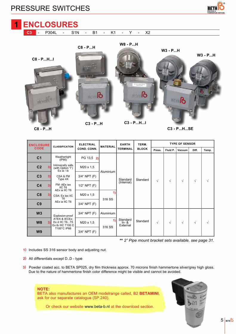
ENCLOSURES C3 - P304L - S1N - B1 - K1 - Y - X2
W3 - P...H
W8 - P...HW3 - P...H
C3 - P...H...SEC3 - P...H...IC3 - P...H
C8 - P...H
C8 - P...H
C8 - P...H...I
1
** 2” Pipe mount bracket sets available, see page 31.
1)
2)
Includes SS 316 sensor body and adjusting nut.
All differentials except D..D - type
Powder coated acc. to BETA SP025, dry film thickness approx. 70 microns finish hammertone silver/grey high gloss. Due to the nature of hammertone finish color difference might be visible and cannot be avoided.
NOTE: BETA also manufactures an OEM modelrange called, B2 BETAMINI, ask for our separate catalogue (SP.240).
Or check our website www.beta-b.nl at the download section.
3)
PG 13,5
M20 x 1,5
3/4“ NPT (F)
M20 x 1,5
1/2” NPT (F)
3/4“ NPT (F)
M20 x 1,5
ENCLOSURE CODE CLASSIFICATION
ELECTRIAL COND. CONN.
MATERIAL
Weathertight(IP66)
Intrinsically safe (with Option “I”)
Ex ia / ib
CSA & FM Type 4X
FM: AEx iex IIC T6
AEx ia IIC T6
CSA: Ex iex IIC T6
AEx ia IIC T6
Explosion-proofATEX & IECEx: Ex d IIC T6...T5
Ex tb IIIC T100 CT100°C IP66
Aluminium
316 SS
Aluminium
316 SS
Standard(Internal)
StandardIn- &
External
Standard
Standard
EARTHTERMINAL
TERM. BLOCK
TYPE OF SENSOR
Fluid P. Vacuum Diff. Temp.
C1
C2
C3
C4
W3
W8
C8
√ √ √ √ √
√ √ √ √ √
1)
1)
W9 3/4“ NPT (F)
3/4“ NPT (F)C9
Press.
2)
3)
3)
3)
3)
3)
5

“Ranges” given here are valid for setpoints at increasing pressures (also vacuum) of the high end of the range and decreasing for the low end of the range.
The “Deadband” values are the max. possible values for a standard micro switch & diaphragm/ O-ring combination.Deanband and varies nearly linear with setpoint between indicated limits of range and should be multiplied by deadband multipliers as given in section 4 and 5, where appropriate. For Fluid Power multiplier acc. to section 5 only.
Selection of other than standard micro switch may influence the lower end of range.
Stability of setpoint around 0 bar gauge, is not guaranteed.
Only available with L1 -micro switch element.
RANGES for Fluid power switches
RANGES for Vacuum switches
PRESSURE SWITCHES
RANGES for Pressure switches C3 - P304L - S1N - B1 - K1 - Y - X2
Fluid Power switches are to be used on clean, lubricating fluids only.
P 301 L
P 808 HP 908 HP 909 H
P 302 L
RANGE CODE ADJUSTABLE RANGE MAX. DEADBAND MAX. OVERRANGEPRESSURE PROOF PRESSURE
1) P 304 LP 306 L P 308 LP 402 MP 404 MP 406 MP 408 MP 502 HP 504 HP 506 HP 508 H
P 708 HP 706 H
[2 - 15][10 - 100][20 - 240][20 - 560][25 - 1300]
[150 - 5400]
0.5 - 9.00.4 - 3.50.3 - 1.6
[100 - 400][100 - 950][120 - 2300]
0.7 - 21.52.5 - 323.0 - 76
10 - 3004.0 - 170
10 - 350
[2.5 - 3.5][6 - 9][6 -12][7 - 15][15 - 20][15 - 30][16 - 50][16 - 90][65 - 95][65 - 160][65 - 330]
0.3 - 1.65
[70 - 810]
0.3 - 3.750.8 - 9.52.0 - 19.52.0 - 25
10 bar
30 bar
125 bar
200 bar
400 bar
15 bar
35 bar
140 bar
600 bar
[1.1 - 1.9]mbarmbarmbarmbarmbarmbarmbarmbarmbarbarbarbarbar barbarbarbarbar
mbarmbarmbarmbarmbarmbarmbarmbarmbarmbarmbarmbarmbarbarbarbarbarbar
1)
RANGE CODE ADJUSTABLE RANGE(INCR. VAC. TO PRESS.) MAX. VACUUM MAX. OVERRANGE
PRESSURE
V 404 MV 406 MV 506 H
V 304 L[mbar]
[-60/0/+150][-400/0/+400][-980/0/+1000]
-1/0/+6
[4/4/6.5]
[16/16/25]
[30/30/40]
[80/80/25]
[-500]
-1
-1
+30
+200
+35
+140
+600
MAX. DEADBAND(VAC. / PRESS.)
[mbar] [mbar] bar bar
[mbar]bar bar bar
V 301 L [-10 to -3] [1] [-500] +10 +15
[mbar]
[mbar]
bar
[mbar]
[mbar]
[mbar] bar
+125
bar bar
[mbar] bar bar[mbar]
PROOF PRESSURE1)
RANGE CODE ADJUSTABLE RANGE MAX. DEADBAND MAX. OVERRANGE PRESSURE PROOF PRESSURE
P 906 FP 908 FP 918 F
P 904 F 12 - 5516 - 13020 - 30030 - 540
3.5 - 6.0
15 - 31 6 - 12 4.0 - 8.5
650 bar 700 bar
barbar
barbar
bar
barbar
bar
2)
2
300 bar
1)
**
For setpoint around 0 bar gauge, please consult your local representative.1)
2)6

PRESSURE SWITCHES
RANGES for Bi-Directional
C3 - D352H - S1N - B1 - K1 - Y - X2
RANGES for Differential switches
30
bar
ADJUSTABLE RANGEDIFF. RANGERANGE CODE MAX. STATIC
PRESSUREMAX. OVERRANGE
PRESSUREPROOF
PRESSURETYPICAL
DEADBAND
bar
1)
D 359 H
D 302 L
D 304 LD 306 LD 309 LD 402 MD 404 MD 406 MD 408 MD 506 MD 508 MD 608 MD 352 HD 354 HD 356 H
1)
[12 - 75] [22 - 180][25 - 450][35 - 1250]
0.3 - 1.00.5 - 2.51.0 - 6.01.0 - 14.5
5 - 2010 - 5010 - 70
[80 - 160][100 - 500]
[120 - 1450][150 - 3450]
[7][8][11][15]
0.15
0.2
0.8
1.5[25][35][50][75]
30
10
50
100
140
200
3)
140 5)
200 5)
35
140
200
[mbar]
[mbar]
[mbar]
bar
[mbar]
bar
barbar
bar
barbar
[mbar]
[mbar]
[mbar]
[mbar]
bar
bar
bar
bar[mbar]
[mbar]
[mbar]
[mbar]
bar
bar
bar
bar
bar
bar
bar
bar
bar
bar
bar
[mbar]
[mbar]
[mbar]
[mbar]
P 301 L-..-D [2 - 15] [mbar] [1,1-1,97] [mbar] 10 10 bar 15 bar4) 6)
2
2) 2)
bar
Example:
D…H - type Diff. setpoint: 1 bar (1000 mbar). If static pressure increases 10 bar then the differential setpoint will be: (10 times – 2 mbar ) = 20 mbar - 1000 mbar = 980 mbar.
NOTE: For differential application outside above ranges consult your BETA Representative.
D 356 D [100 - 1500] [35 - 65]200 200 200
D 358 D [100 - 3500] [45 - 115]5) barbar
[mbar]
[mbar]
[mbar][mbar]
D...LD...MD...H
- 0.7 mbar/bar
= + 3 mbar/bar
- 2 mbar/bar
= - 0.1 mbar/bar
+ 10 mbar/bar
= - 0.4 mbar/bar
SETPOINT DEADBANDSENSOR
P301L-...D = + 0.1 mbar/bar = + 0.1 mbar/bar
Ranges and deadbands are given at 50% of Max. Static pressure. All differential pressure sensors are sensitive to static pressure, both for setpoint and deadband.
Range only with L1 micro switch.
D…L can withstand a differential pressure P-Low max. 1 bar above P-High.
P 301L...D can withstand a differential pressure P-Low max. 100 mbar above P-High.
D…M, D…H and D…D can sustain full High and Low-side reversal.
Only available with G3-enclosure. - For more details, page 16.
1)
2)
3)
4)
5)
6)
NOTES:
THE FOLLOWING TABLE SHOW THE INFLUENCE FOR INCREASING STATIC PRESSURE:
7

PRESSURE SWITCHES
PROCESS CONNECTIONS C3 - P304L - S1N - B1 - K1 - Y - X2
(Standard) process connection for “L”ow pressure sensor body : S1N or S1B “M”edium & “H”igh pressure sensor body : S1N or S1B “F”luid power pressure sensor body : B1N or B1B Differential switches: D…H, D…D, D...M : S1N or S1B only D…L : A1N or A1B; For Low side only High side: Only “L”-sensor connections
Vacuum switches: Process connection size max. 1/2”. Vacuum piston & spring (both wetted) standard in 316 SS.
Not
for
vacu
um
PROCESS CONNECTION SIZE/ CODE
WITH SENSORSS 316 MONEL BRASSALUMINIUM
NPT BSP NPT BSP NPT BSP NPT BSP
1)
1/4”F
1/2”F
1/2”M
1”F2”F
1”M
F
D...L (Low side)
H / M / D...MD...H / D
F
LD...L (High Side)
H / M / D...M
L, M & HD...L / M (High Side)
L & D...L (High Side)L & D...L (High Side)
M & HD...M
A1N A1B S1N S1B
S2N S2B
S7N S7B
S4N S4BS6N S6B
M1N M1B
M2N M2B
B1N B1B
B2N B2B
B6N B6B
M7N M7B
1/2” GaugeConnection
HL & M S7G
S8N S8B
2)
L
D...L (High Side)
3
1)
2)
NOTES: • Process connection according to NACE standards are available, consult your BETA Representative.
Materials such as PVC, Hastelloy, Titanium, special sensor sizes and Teflon lined flanged connections are available on request.
8

Wetted parts are suggested for use on the service indicated. However they do not constitute a guarantee to be suitable for a given process against corrosive or permeation since processes vary from plant to plant. Empirical experience by users should be the final guide. The diaphragm / O-ring combinations are for process temperatures of -30°C to +80°C, unless otherwise indicated. For process temperatures beyond these limits please contact your BETA Switch Representative.
Switches for fluid power applications are limited to these options (O-ring only with 316SS piston).
Only for 1/4” & 1/2” process connections. Not available on vacuum switches. For other sizes and materials, consult your BETA Switch Representative.
PTFE O-ring not suitable for vacuum switches or vacuum surge conditions. (Wetted internal spring of Co-Cr-Ni-Mo alloy, comparable with Elgiloy).
For process temperature > 100°C, consult your BETA Switch Representative.
Other diaphragm materials like Hastelloy available, consult your BETA Switch Representative.
High temperature refers to max. 130°C at process connection.
PRESSURE SWITCHES
DIAPHRAGM / O-RINGS C3 - P304L - S1N - B1 - K1 - Y - X2
KalrezEPDMBuna-N
Process temperature NOT below minus 10°C.
None
Viton-A
PTFE
Viton-APTFE
Viton-A
PTFE
Viton-ABuna-N
Neoprene
Viton-A
PTFE
DIAPHRAGM / O-RING CODE O-RING USE DEADBAND
MULTIPLIER
B1
DIAPHRAGM
E6
K5
M1 M2
M4 M5 N3
P1
P2
P4P5
S1 S2 S3 S4
S5
S6 T1 T2
T3 T4 T5
V2 S0
M0
Buna-N
6)
EPDMKalrez
Monel
Neoprene
PTFE(Polyimide coated
with PTFE)
SS 316
Tantalum
Viton-ASS 316Monel
Welded diaphragm
Kalrez
Buna-N
KalrezBuna-N
Neoprene
KalrezEPDMBuna-N
Neoprene
Kalrez4)
Standard water / oil (-30°C to +80°C).Some hydraulic fluids, steam condensate.
Highly corrosive fluids.Seawater.
Process temperature NOT below minus 10°C.Corrosive acids.
Highly corrosive and permeative acids.When required.Oil / air / water.
Process temperature NOT below minus 10°C.Corrosive acids.Corrosive acids.
Permeative gases.
Permeative refrigerant gases.Corrosive acids.
Highly corrosive and permeative acids.Steam. (Not for steam condensate)
Highly corrosive and permeativr gases and non-acid liquids.
Select O-ring as required.
Process temperature NOT below minus 10°C.
Highly permeative gases.
1.01.01.5
2.0
1.0
1.5
2.0
2.0
1.5
3.0
2) 2) 2) 5) 4)
2)
5) 4)
5)
4)
5)
2) 5)
3)
7)
7)
7)
7)
1)
4
1)
2)
3)
4)
5)
6)
7)
9
7)

DIFFERENTIAL PRESSURE SWITCHES
DIAPHRAGM / O-RINGS C3 - D352H - S1N - P1 - K1 - Y - X2
Differential Pressure Switches include a similar type of Diaphragm/O-ring combinations as for Pressure Switches,but the following must be considered:
Note: Deadband Multiplier for Diaphragm/O-Ring and switching element are similar as for a pressure switch.
TYPE STANDARD FOLLOWING COMBINATIONS ARE POSSIBLE
P301L/ D...L
D...M
D...H
D...D
B1
B1
P1
P1
All except with PTFE O-Ring and Welded diaphragm.
All diaphragm and O-Ring combinations.
W3 - D...L
C - D...LC3 - D...L
C8 - D...L
W8 - D...L
W3 - D...H C3 - D...HW8 - D...HC8 - D...H
* Cut-a-away model
Metal + TCP.
Metal + TCP.
4
10

PRESSURE AND TEMPERATURE SWITCHES
SWITCHING ELEMENTS C3 - P304L - S1N - B1 - K1 - Y - X2
For D.P.D.T. action second code figure should be specified as “2” (Example: K1 = S.P.D.T ./ K2 = D.P.D.T.).
Actual capacitive or inductive load under VDC may influence the setpoint repeatability.
Not on Differential pressure switches (except for “SR”-micro in “W”-enclosure).
VDE certified acc. to. DIN EN 61 058-1:1992+A1:1993.
“SR”-and “H1”-micro switches, with high multiplier, can affect the low end of a range.
“SR”-micro in combination with metal diaphragm: standard with option “P”.
For pneumatic element (select C1 or C8 enclosure) or ask your BETA representative for Air Relay documentation.
For DC rating resistive loads are stated.
In “W...” Enclosure max 10A current rating allowed, will be stated on the nameplate.
Subminiature microswitch, only possible with selection for DPDT configuration for W-enclosure.
** DC rating not U.L. listed, although experience and third party testing confirm the DC voltage ratings. Consult your BETA Switch Representative.
SWITCHINGELEMENT CODE USE
MAX. RATINGS (RES.) DEADBAND MULTIPL.
VAC. VDC 8) S.P.D.T. D.P.D.T.
1)
K1L1 4)
M1
U1 9) G1 4) Y1O1N1
Z1
SPSR 6)9) SE 3) SG 3) SVSA
3)
SB 3)
General-service
DC-service
Low voltage circuit (Gold contacts)
Gold contactsSilver contacts
For higher (amb.) temp.
Adjustable deadband
Manual reset
Herm. sealed
PneumaticAIR Relay
Normal DC-service.
Standard.
Standard for P/D301L & P/D302L ranges.
High DC cap. magnetic blow out.
For use in H2S environment and/or for (EEx)i applications.
Environmental proof (IP 67).
Environmental proof (IP 67).
Nickel Alloy spring. For corrosive environment.
Small adjustable deadband.
Wide adjustable deadband.
Actuates automatic on increasing pressure.
Actuates automatic on decreasing pressure.
(Inert gas filled) Dusty, corrosive environment.
Normally closed (NC).
Normally open (NO).
480/ 15A 28/ 0.5A 1.0 1.5480/ 10A 28/ 0.5A 1.0 -
250/ 5A 30/ 5A 1.5 3.5
480/ 15A 125/ 0.5A 2.5 4.0
125/ 10A 125/ 10A 5.0
125/ 1A 28/ 0.5A 1.5 2.030/ 0.1A 3.0 4.5
250/ 0.1A 30/ 0.1A 3.0 4.5 250/ 2A 30/ 2A 3.0 4.5
250/ 5A 125/ 0.3A 3.0 4.5
250/ 15A - 1 to 3
S.P.D.T. only
480/ 20A - 2 to 6480/ 15A 125/ 0.5A 1.5480/ 15A 125/ 0.5A 1.5
125/ 1A 28/ 15A 5.0
For use in explosive atm. Ex II 2G c T6
KEMA 04ATEX4060Consult BETA Switch Rep. Single Only
125/ 0.1A
**
**
5) 3)
7)
2)
H1 (SL) 6.5
R1 Ex. Proof. ATEX approved. (Std. on Z-series) 250/ 5A 250/ 0.25A 2.5 4.5
Standard DPDT configuration on W-series when required.
4) 9)
10)
10) 10) 10)
10)
2)
5
1)
2)
3)
4)
5)
6)
7)
8)
9)
10)
Note:• Micro switches both for single and double action respectively SPDT and DPDT, are intended to be set for one setpoint and one direction only.• The deadband reset value is a result of the complete modelcode selection and actual switch asssembly, so except for the SR/SP microswitch, the reset switching point is fixed and cannot be controlled by the manufacturer.• Please keep in mind that even within a series of similar model, the reset switching point can vary.• Proper application of SR and SP micro switches requires accurate statement of values to the setpoint and required reset
setpoint.
If you have any specific question or requirement contact us at: [email protected]
11

PRESSURE AND TEMPERATURE SWITCHES
“SA” / “SB” only with C3 enclosure, pneumatic connection (Brass) and C8 enclosure with SS316 connection.
The standard switching elements are:
• “K1” for C- and W- enclosures. • “L1” for P301L/ P302L/ D302L range.
POSSIBLE
NOT POSSIBLE
C3 - P304L - S1N - B1 - K1 - Y - X2
SWITCHING ELEMENTS VS. ENCLOSURES
3-WAYTERMINAL BLOCK
3-WAYTERMINAL BLOCK
2 X 3-WAYTERMINAL BLOCK
4-WAY TERMINAL BLOCK
7-WAYTERMINAL BLOCK
1/4 NPT (F)CONNECTIONS
4-WAYTERMINAL BLOCK
SWITCHING ELEMENT W3, W8, W9C1, C2, C3, C4, C8, C9Internal
Earth Ground Terminal
ENCLOSURE
Internal & ExternalEarth Ground Terminal
SE SG SP SR SV
G1
H1 (SL) K1
L1
U1 O1 N1
M1 Y1 Z1
M2 Y2Z2
G2 H2 K2U2
O2
N2
SA
SB
SPD
T SI
NG
LE P
OLE
DO
UBL
E TH
RO
WD
PDT
DO
UBL
E PO
LE D
OU
BLE
THR
OW
*
*
R2
2 X 3-WAYTERMINAL BLOCK
R1
7-WAYTERMINAL BLOCK
5
12

PRESSURE SWITCHES
Tag no. space on nameplates are added free of charge
3) Standard nameplate C-Series : 2 lines with 16 characters or spaces + 1 line with 14 characters or spaces. W-Series : 1 line with 16 characters or spaces. 4) Air dried system acc. to BETA procedure, dry film thickness approx. 200 µm, finish pearl grey gloss.
C3 - P304L - S1N - B1 - K1 - Y - X2
OPTIONS
OPTION CODE DESCRIPTION
B Industrial cleaning of “wetted” parts for oxygen services.
C Cable gland (Weather proof IP66, Ex e, Ex i, Ex d in acc. with classification of enclosure).
I Intrinsically safe application (Ex e, Ex i, Ex d). Only on “C”-Series (90V/ - 3.3A).
M Vacuum protector plate (Not on Vacuum-, Fluid Power-, D...H- and D...D Switch) (Standard on D...L).
P Recommended on strong process pulsations. Only on “H”-Sensors. Not in combination with EPDM, Neoprene, Viton-A and Kalrez diaphragms.
S Stainless steel Tag key ringed to enclosure. Tag has 2 lines (16 characters per line).
V Fungicidal varnish coating (internal).
Y Epoxy coating of switch (external). Only in combination with SS 316 process connection.SS Parts are not coated.
3)
4)
6
1)
13
1) Option B - Oxygen cleaning acc. SP19. Not possible for D..H ranges/ for G3-P301L-..D and D..L ranges on Hi-side connection only.
2)
2) Option M - Is only to intend to provide a limited protection against surge/ vacuum conditions, as which can occur during start-up conditions or repetitive applications (pumps/ compressor). So short occurances over a limited period of time.
It is not intended for continous surge/ (full) vacuum conditions over an extended period of time.
Indication:
P4..MP5-7-8-9..H
-200 mBarg
-600 mBarg
60
90
Max. Surge Pressure Approx. period of time (minutes)RANGE
P3..L -200 mBarg 60
• Values stated here for indicative purpose only, they do not constitute any true value or any kind of warranty.
• Option M - is considered as wetted part and as such is explicitly excluded from the BETA factory warranty.

We can incorporate many specials to meet your requirements. These special requirements are indicated by the letter “X” in the modelcode positioned or at the end of the model number, followed by a figure showing the number of specials.
Example:
“X1” at the end of modelcode “X2” at the end of the modelcode Details of each special must bereference means one special. reference means two specials specified completely on enquiries and have been incorporated. orders.
Example for specials for BETA switches are:
• Flanged connection 3/4” to 3” (ANSI or DIN).• Range indication in Pa, Kg/cm2, mm H20 or mmHg.• Breakwire resistor acc E12 range for line monitoring (Only for C-enclosure).• Hirschmann or Harting Connector.• Moisture inhibitor.• Chemical seals.
SPECIALS C3 - P304L - S1N - B1 - K1 - Y - X2
7
PRESSURE AND TEMPERATURE SWITCHES
14

See section 1. Enclosure on page 5.
RECAPTURE: HOW TO SELECT YOUR BETA SWITCH
ENCLOSURES C3 - P304L - S1B - S2 - K1 - Y - X2
See section 2. Range on page 6, and 7.
RANGES C3 - P304L - S1B - S2 - K1 - Y - X2
See section 3. Process connections on page 8.
PROCESS CONNECTIONS (Material / Size / Thread) C3 - P304L - S1B - S2 - K1 - Y - X2
See section 4. Diaphragm / O-rings on page 9 and 10.
DIAPHRAGM / O-RINGS C3 - P304L - S1B - S2 - K1 - Y - X2
See section 5. Switching Elements on page 11 and 12.
SWITCHING ELEMENTS C3 - P304L - S1B - S2 - K1 - Y - X2
1
2
3
4
5
Selection of your switch is now completed.
If required: For “Optional“ and “Special“ requirementsOptions : See section “6. Options” on page 14.
Specials: See section “7. Specials” on page 14.
15
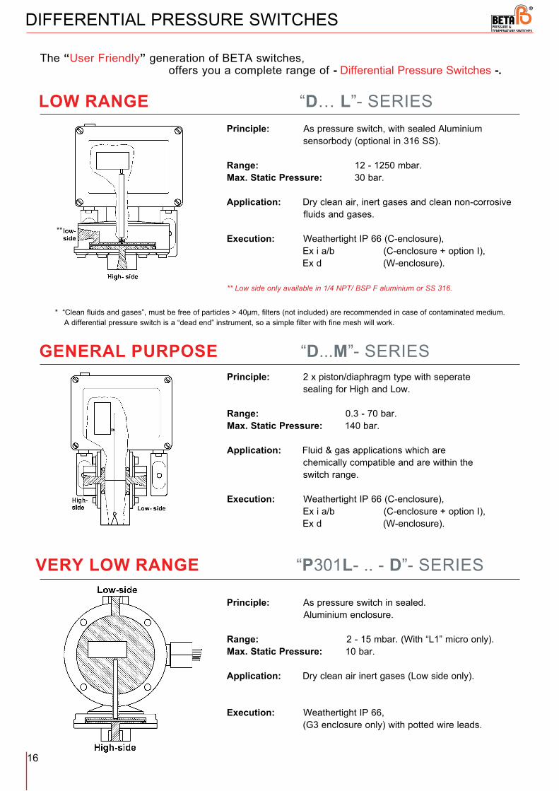
LOW RANGE “D… L”- SERIES
DIFFERENTIAL PRESSURE SWITCHES
GENERAL PURPOSE “D...M”- SERIES
Principle: As pressure switch, with sealed Aluminium sensorbody (optional in 316 SS). Range: 12 - 1250 mbar. Max. Static Pressure: 30 bar.
Application: Dry clean air, inert gases and clean non-corrosive fluids and gases.
Execution: Weathertight IP 66 (C-enclosure), Ex i a/b (C-enclosure + option I), Ex d (W-enclosure). ** Low side only available in 1/4 NPT/ BSP F aluminium or SS 316.
Principle: 2 x piston/diaphragm type with seperate sealing for High and Low. Range: 0.3 - 70 bar. Max. Static Pressure: 140 bar.
Application: Fluid & gas applications which are chemically compatible and are within the switch range.
Execution: Weathertight IP 66 (C-enclosure), Ex i a/b (C-enclosure + option I), Ex d (W-enclosure).
**
VERY LOW RANGE “P301L- .. - D”- SERIES
Principle: As pressure switch in sealed. Aluminium enclosure. Range: 2 - 15 mbar. (With “L1” micro only).Max. Static Pressure: 10 bar.
Application: Dry clean air inert gases (Low side only).
Execution: Weathertight IP 66, (G3 enclosure only) with potted wire leads.
* “Clean fluids and gases”, must be free of particles > 40µm, filters (not included) are recommended in case of contaminated medium. A differential pressure switch is a “dead end” instrument, so a simple filter with fine mesh will work.
The “User Friendly” generation of BETA switches, offers you a complete range of - Differential Pressure Switches -.
16

* “Clean fluids and gases”, must be free of particles > 40µm, filters (not included) are recommended in case of contaminated medium. A differential pressure switch is a “dead end” instrument, so a simple filter with fine mesh will work.
DIFFERENTIAL PRESSURE SWITCHES
LOW RANGE / HIGH STATIC “D… H”- SERIES
Principle: Piston type with single diaphragm, sealed in 316 SS sensorbody.
Range: 80 – 3450 mbar Max. Static Pressure: 200 bar
Application: Clean fluids and gases*, provided acceptable choice of wetted parts is within our range. Execution: Weathertight IP 66 C-enclosure, Ex i a/b C-enclosure + option I, Ex d W-enclosure ** Low and High side, only available in 1/4 NPT/ BSP F, SS 316.
LOW RANGE / HIGH STATIC “D...D”- SERIES
Bi-Directional Differential Pressure Switch
Principle: Piston type with single diaphragm, sealed in 316 SS sensorbody.
Range: 0,1 – 3,5 bar Max. Static Pressure: 200 bar
Application: Clean fluids and gases*, provided acceptable choice of wetted parts is within our range.
Typical application: Natural gas pipelines, safe guarding high pressure pipeline valves against being opened at too high differential pressure from either side.
Execution: Weathertight IP 66 C-enclosure, Ex i a/b C-enclosure + option I, Ex d W-enclosure. ** Neg./ Pos. side only available in 1/4 NPT/ BSP F, SS 316.
**
**
**
**
17

TEMPERATURE SWITCHES
TEMPERATURE SWITCH
The BETA Temperature Switch is a pressure switch enclosure incorporating a sealed 2-phase (vapor/liquid) temperature sensor.When the temperature of the process increases, the vapor pressure of the liquid increases simultaneously.If this vapor pressure exceeds the pre-adjusted setpoint of the “pressure” switch, it will actuate the switching element.
• Available as direct- or capillary mount sensor.• In weathertight and explosion proof models (ATEX approved).• Fits into most standard thermowells (10,5 mm bore).• No need for ambient temperature compensation (no setpoint shift).• Excellent repeatability/small dead-band.• All 316 stainless steel sensor and capillary (SS armored).• Filling system of gas/liquid acc. to SAMA-Class II C.
“C” - Series with Direct mount type sensor
EXPLOSION-PROOF TEMPERATURE SWITCH
ATEX, IECEx, CSA & FM, approved up to the highest classification (see page 23).
With the W-enclosure or the C-enclosure Option i, the BETA Temperature Switch is approved for ATEX, IECEx, FM, CSA and several more, a.o. acc. EN 60079 standards
“W” - Series with Capillary type sensor
18

TEMPERATURE SWITCHES
ENCLOSURES C3 - T548H - D00 - S0 - K1 - Y - X2
W3 - T...H-D00W3 - T...H-C03 W8 - T...H-C03
W8 - T...H-D00
C8 - T...H-D00C3 - T...H-D00
1) Includes SS 316 sensor body and adjusting nut.
SS 316
ENCLOSURE CODE CLASSIFICATION MATERIAL EARTH TERMINAL TERM. BLOCKELECTRIAL
COND. CONN.
C1
C2
C3
C4
C8
Weathertight (IP66)
Intrinsically safe (with Option “I”)
SS 316 1)
PG 13.5
M20 x 1.5
3/4” NPT (F)
1/2” NPT (F)
M20 x 1.5
3/4” NPT (F)
M20 x 1.5
Aluminium
Aluminium
Standard (Internal) Standard
Standard In- & External Standard
W3
W8
C9 3/4” NPT (F)
W9 3/4” NPT (F)1)
Explosion-proofATEX & IECEx: Ex d IIC T6...T5
Ex tb IIIC T100 CIP66
1
19

TEMPERATURE SWITCHES
C3 - T548H - D00 - S0 - K1 - Y - X2
1) In case process temperature > 140°C, Direct mount sensing bulb is not recommended.2) Not in combination with Direct mount sensing bulb.3) For deadband calculation in combination with “SR”- and “SP”- micro, consult your BETA representative.
W3 - T...H - D00W8 - T...H - D00
C3 - T...H - D00 C8 - T...H - D00
W3 - T...H - C03
T 568 H
MAX TYPICAL. DEADBANDRANGE CODE ADJUSTABLE
RANGEMAX.
TEMPERATUREPROOF
TEMPERATUREMAX. PROCESS
PRESSURE
°C
bar
T 528 H
T 548 H
T 588 H
1)
2)
-40 / +40
0 / +95
+60 / +180
+160 / +300
3
3.5
+125
+200
+300
+400
+200
175+250
+350
+450
°C
°C
°C
°C
°C
°C
°C
°C
°C °C
°C
°C
°C
3)
RANGES2
20

The standard Switching elements are: “K1” for C - and W - enclosures
Deadband Multiplier micro switch element similar as for pressure switch.For other available switching elements and additional technical information see 5 on pages 11 and 12.
SWITCHING ELEMENTS C3 - T548H - D00 - S0 - K1 - Y - X2
Note: All SS 316 stainless steel sensor, capillary (SS 304 armored) and compression fitting.
1) Not in combination with range T588H (+160/+300 ˚C), not recommended with T568H in case of process temperature >140 ˚C.
2) Length of capillary should be specified, consult your BETA Switch Representative. (Max.:15 mtr.)
** Thermowells available, see page 30.
All temperature switches have “S0” welded diaphragm.
SENSOR BULBS C3 - T548H - D00 - S0 - K1 - Y - X2
PROCESS CONNECTION TYPE OF TEMPERATURE SENSING BULB
D00
1/2” NPT (M)
128 mm length
D02
C02
C03
C05
225 mm length
2 m. capillary length
3 m capillary length
5 m. capillary length
10 m. capillary length
Special capillary length
Direct mount.
Capillary mount.
C10
CXX
SENSOR CODE
1)
2)
DIAPHRAGM / O-RINGS C3 - T548H - D00 - S0 - K1 - Y - X2
TEMPERATURE SWITCHES
3
4
5
21

BETA can incorporate many specials to meet your requirements. These special requirements are indicated by the letter “X” in the model code or at the end of the model number, followed by a figure showing the number of specials.
Example:
“X1” at the end of modelcode “X2” at the end of modelcode Details of each special mustreference means one special. reference means two specials always be specified completely have been incorporated. on enquiries and orders.
Tag no. space on nameplates __ added free of charge
Standard nameplate C-Series : 2 lines with 16 characters or spaces + 1 line with 14 characters or spaces W-Series : 1 line with 16 characters or spaces
TEMPERATURE SWITCHES
OPTIONS C3 - T548H - D00 - S0 - K1 - Y - X2
OPTION CODE DESCRIPTION
C Cable gland (weather proof IP66, Exe, Exi or Exd in acc. with classification of enclosure).
I Intrinsically safe application (EEx)i. Only on “C”-Series.
S Stainless steel Tag key attached to enclosure. Tag has 2 lines (16 characters per line).
V Fungicidal varnish coating (internal).
Y Epoxy coating of enclosure and sensorbody (external).
SPECIALS C3 - T548H - D00 - S0 - K1 - Y - X2
6
6
22

The “BETA Switch” is a safety instrument and adds an extra dimension to industrial safety because a wide selection of switches is available up to safety level Category 2 for hazardous areas (e.g. ATEX, IECEx)
Benefits
• Worldwide agency approvals.• “User Friendly” Modifications – Standard features incorporated for your safety.• Minimal amount of wetted parts - minimal maintenance needed.• High overrange pressures allowed without setpoint shift or damage of functional parts • Designed for reliability over the full life cycle time.
W-SeriesATEX: ITS 17ATEX 101854 X Ex II 2 G Ex db IIC T6 . T5 Gb T6 -60°C < Tamb < +70°C / T5 -60°C < Tamb < +80°C Ex II 2 D Ex tb IIIC T 100 °C Db -60°C < Tamb < +80°C
IECEx IECEx ITS 17.0019 X Ex db IIC T6 Gb - 60°C < Tamb < +70°C Ex db IIC T5 Gb - 60°C < Tamb < +80°C Ex tb IIIC T 100 °C Db -60°C < Tamb < +80°C
CSA: CERT.:1873316 acc. to Class 2258-02 Class I, Div. 1, Groups B, C, D T6/ -40 to +70°C, T5/-40 to +80°C Class II, III, Div.1, Groups E, F and G Ex d IIC T6...T5 Enclosure Type 4X, IP66
FM: CERT.:3028962 Class I, Div. I, Groups A, B, C and D, T6 Ta = -40 to +70°C, T5 T1 = -40 to +80°C Class I, Zone I, AEx d IIC, T6 Ta =+70°C, T5 Ta = +80°CDIP, Class II/III, Div.1, Groups E, F and G, T6 Ta = +70°C, T5 Ta = +80°C Enclosure Type 4X, IP66
C-Series Intrinsically safeATEX: CERT.: KIWA 15 ATEX 0023X Ex II 1 G Ex ia IIC T4...T6 Ga or Ex II 2 G Ex ib IIC T4...T6 Gb Ex II 1 D Ex ia IIIC T 85°C Da or EX II 2 D Ex ib IIIC T 85°C Db Amb. Temp.: -60°C to +80°C
IECEx: CERT.: KIWA 15.0011X Type of protection: Exia Ex ia IIC T6 Ga Ex ia IIIC T 85°C Da
BETA SWITCHES FOR HAZARDOUS AREA
CSA: CERT.:1891054 acc. to Class 2258-04 IS Class I, II, III, Div.1, Groups A, B, C, D, E, F and G Ex ia IIC T6 T85°C Amb. Temp.: -40 to +80°C Enclosure Type 4X
FM: Cert. No. 3031247 IS Class I, II and III, Div. 1, Groups A, B, C, D, E, F, G Class I, Zone 0, AEx ia IICT6, -40°C <Ta < +80°C Enclosure Type 4x
BETA offers complete line of switches for (classified) hazardous area!
23

BETA SWITCHES FOR HAZARDOUS AREA
BETA has its “C”-Series switches with option “I” certified by KIWA acc. to NEN EN 60079-0 / EN 60079-11 for, II 1 G Ex ia IIC-T4...T6 Ga or II 2 G Ex ib IIC-T4...T6 Gb or II 1 D Ex ia IIIC T85°C Da or II 2 D Ex ib IIIC T85°C Db
ATEX approved : KIWA 15 ATEX 0023X (-60 to +80°C)IECEx approved : KIWA 15.00IIX (-60 to +80°C)CSA approved : Cert.No.: 1891054 (-40 to +80°C)FM Approved : Cert. No.: 3031247 (-40 to +80°C)(For more information see also page 23)
This option includes all required installation materials including a blue colored EEx e approved terminal block and the (standard) earth terminal.
Option “I” in accordance with art. 9 of the ATEX Directive 94/9/EC (Ex ia/ib IIC) which are related to insulation, clearance, creepage distances and enclosure type whereby a max. peak voltage of 90 V or 3,3A is allowed.
“C”- Series (Intrinsically safe application EEx i).
Please note the following:
When a switch is ordered with cable gland (option “C”) BETA will automatically install the EEx i blue cable gland (see drawing). Due to low current used in intrinsically safe systems we recommend the use of switching elements with gold contacts. (code “G1,” “O1” or “Y1”).
C-Series (Intrinsically safe) - ATEX, IECEx, CSA and FM approved.
“C” - Series
BETA “C” - Series with option “I” for intrinsically safe systems.
(See also page 22)
24

BETA SWITCHES FOR HAZARDOUS AREA
W-Series -ATEX, IECEx, CSA and FM approved.
Separate adjustment compartment allows easy field calibration.Due to the wide selection of materials and components parts, virtually all applications can be covered.
ATEX approved: ITS 17ATEX 101854 X IECEx IECEx ITS 17.0019 X* For Gas : Ex II 2 G Ex db IIC T6...T5 Gb Ex db IIC T6....T5 Gb* For Dust : Ex II 2 D Ex tb IIIC T100°C Db Ex tb IIIC T 100 °C Db (For more information see also page 23)
• Aluminium with Extremely rugged powder coated enclosure which is suitable for tough offshore applications. (1000 hrs. Salt spray test acc. to DIN 50021, IEC 60068-2-11 or ASTM B117-90) or 316 SS enclosure.
• Separate adjustment compartment.• Available as Pressure-, Hydraulic-, Vacuum-, Differential pressure- and Temperature switch.• All ranges available.• Highest overrange protection.• Excellent for field mounting (2” Pipe SS mounting bracket available), see page 31.• Epoxy coating optional.• Also available in SS316.
“W” - Series
The “W”-series is a worldwide best seller.
25

SIL 2 certification:In order to state SIL2 compliance based on the standard IEC 61508, please consider the following conditions:
Always read the BETA installation, Operation, Safety Manual before installation, setting and testing is started Installation, setting and testing may only be performed by qualified personnel using calibrated equipment and based on the approved SIL I.O.S Manual Instruction.
BETA is not responsible for changes in settings out of BETA production
EXPLOSION-PROOF CERTIFICATIONS:
Besides the already mentioned explosion-proof certificates, also available are:
Russian market (Commuty Russia, Kazachstan, Belurus)CU TR 012-2011 Ex Safety DirectiveC-series 0Ex ia IIC T6 ... T4 Ga / 1Ex ib IIC T6 ... T4 Gb Ex ia IIIC T85°С Da / Ex ib IIIC T85°С Db
W-series 1Ex d IIC T6 ... T5 Gb Ex tb IIIC T100°С Db X
Korean MarketKorea Industrial Technology InstituteCerticate for explosion safety
JapanJIS
ChinaNepsi Cert No GYJ17 1038X Ex d IIC T5/T6 Gb
OTHER CERTIFICATION:
Europe2014/68/EU Pressure Equipment Directive (PED)C-and W-series Type approval module BQA system Module D CE 0035
Russian Market (Commuty Russia, Kazachstan, Belurus)CU TR 004-2011 Low Voltage Directive Cert Nr. 0705132
Marine Approval B-, C- and W-series type approvalDNV rules for classification:DNV-GL-CG-U339Pressure switches : TAA 0000 2VBTemperature switches : TAA 0000 2VC
More certificates/ reports are available. Please consult your BETA Switch Representative.
BETA PRESSURE & TEMP. SWITCH - CERTIFICATIONS
26

“W.”- Series: Pressure & Vacuum “P...H”“C”- Series: Pressure & Vacuum “P...H”
“C”- Series: Pressure & Vacuum “P...M” “W.”- Series: Pressure & Vacuum “P...M”
“C”- Series: Pressure & Vacuum “P...L” “W.”- Series: Pressure & Vacuum “P...L”
** For specific details about the dimension “A” please consult your BETA representative.
DIMENSIONS
27

DIMENSIONS
“C”- Series: Differential “D...M” “W”- Series: Differential “D...M”
“C”- Series: Differential “D...H” “W”- Series: Differential “D...H”
“C”- Series: Differential “D...L” “W.”- Series: Differential “D...L”
28

DIMENSIONS
“W.”- Series: Bi-directional Differential “D...D”“C”- Series: Bi-directional Differential “D...D”
“C”- Series: Temperature “T..H - D” “W.”- Series: Temperature “T..H - D”
29

DIMENSIONS
“C”- Series: Temperature “T..H-C” “W.”- Series: Temperature “T..H-C”
ACCESSORIESThermowell (SS 316)
INSERTION LENGTH U (MM)
INSERTION ELEMENT LENGTH A (MM)
FIT TO BETA TEMPERATURE SENSING BULB
TW 11 115
TW 15
TW 19
155
190
155
195
228
D00, C02, C03
C02, C03, C05
D02, C02, C03, C05
NOTES:1. BETA Thermowells to be ordered as a separate item. 2. Special Thermowell possible. Consult your BETA Switch Representive.
*** Do not include Thermowell code into the switch code.
CODE
Standard BETA Thermowell
30

2” Pipe mount bracket (SS 304)
Dimensions given here are for 1/4” and 1/2” (F) process connections: For “H”-sensor with 1/2” (F) add 4 mm on “A” dimension. Sizes in mm, tolerances ± 1,5 mm.
“C.”- Series Enclosure on 2” Pipe “W.”- Series Enclosure on 2” Pipe “W.”- Series Enclosure “D...M” on 2” Pipe
2” Pipemount Set (SS 304) Configuration Examples
Contents :
W3 - enclosure 2 x Bracket + 2 x bolts M8 x 100 mm + nut
or
C - series 2 x bolts M6 x 100 mm + washer + nut (Size: +/- 1,5 mm tolerance) / Material SS 304
Disclaimer : This pipe mount bracket is solely intended for use in combination with BETA Pressure & Temperature Switches.
Foundation vibrations, as well as process vibrations, can disturb the proper functioning of the mounted instrument, the use of this bracket does not prevent or diminishes such occurrence.
31

Contact:
OFFICE:
Verrijn Stuartlaan 222288 EL Rijswijk The Netherlands
E-MAIL: TELEPHONE: INTERNET: [email protected] + 31 (0)70 - 319 9700 www.beta-b.nl
BETA Pressure & Temperature switches are designed manufactured in The Netherlands
Note:We reserve the right to make technical changes or modify the contents of this document without prior notice. With regard to purchase orders, the agreed particulars shall prevail. BETA B.V. does not accept any responsibility whatsoever for potential errors or possible lack of information in this document.
We reserve all rights in this document and in the subject matter and illustrations contained therein. Any reproduction, disclosure to third parties or utilization of its contents – in whole or in parts – is prohibited without prior written consent of BETA B.V.Copyright© 2021 - BETA B.V.All rights reserved
Pressure and Temperature SwitchesC & W - series switches
SP-M/20/12/-(FC)