sp 710 owner’s manual - lifespan online
TRANSCRIPT

NOTE: This manual may be subject to updates or changes. Up to date manuals are av ailable through our website at www.lif espanonline. com.au
Product may vary slightly from the item pictured due to model upgrades
Read all instructions carefully before using this product. Retain this owner’s manual for future reference.
SP-710 OWNER’S MANUAL

2
SP-710
TABLE OF CONTENTS
1. IMPORTANT SAFETY INSTRUCTIONS 3
2. EXPLODED DIAGRAM 5
3. PARTS LIST 7
4. ASSEMBLY INSTRUCTIONS 9
5. ADJUSTMENT 14
6. COMPUTER OPERATION 15
7. EXERCISE GUIDE 21
8. WARRANTY REGISTRATION 23

3
SP-710
1. IMPORTANT SAFETY INSTRUCTIONS
WARNING - Read all instructions before using this machine.
It is important your spinning bike receives regular maintenance to prolong its useful life. Failing to
regularly maintain your spinning bike may void your warranty.
1. Keep children and pets away from the machine at all times. Do not leave unattended
children in the same room of the machine.
2. Handicapped or disabled persons should not use the machine without the presence of a
qualified health professional or physician.
3. If the user experiences dizziness, nausea, chest pain, or any other abnormal symptoms,
STOP the workout at once. CONSULT A PHYSICIAN IMMEDIATELY.
4. Before beginning training, remove all within a radius of 2 meters from the machine. DO
NOT place any sharp objects around the spin bike.
5. Position the machine on a clear, level surface away from water and moisture. Place mat
under the unit to help keep the machine stable and to protect the floor.
6. Use the machine only for its intended use as described in this manual. DO NOT use
any other accessories not recommended by the manufacturer.
7. Assemble the machine exactly as the descriptions in the instruction manual.
8. Check all bolts and other connections before using the machine for the first time and
ensure that the trainer is in the safe condition.
9. Hold a routine inspection of the equipment. Pay special attention to components which
are the most susceptible to wear off, i.e. connecting points and wheels. The defective
components should be replaced immediately. The safety level of this equipment can
4
SP-710
only be maintained by doing so. Please don't use the machine until it is repaired well.
10. NEVER operate the machine if it is not functioning properly.
11. This machine can be used for only one person’s training at a time.
12. Do not use abrasive cleaning articles to clean the machine. Remove drops of sweat
from the machine immediately after finishing training.
13. Always wear appropriate workout clothing when exercising. Running or aerobic shoes
are also required.
14. Before exercising, always do stretching first.
15. The power of the machine increases with increasing the speed, and the reverse. The
machine is equipped with adjustable knob, which can adjust the resistance.
5
SP-710
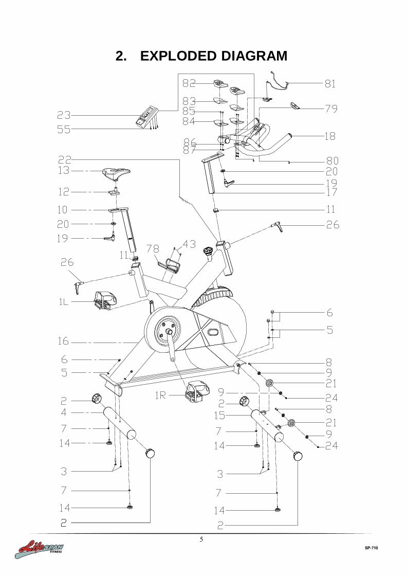
2. EXPLODED DIAGRAM

6
SP-710

7
SP-710
3. PARTS LIST
NO NAME QUANTITY SPEC
1L PEDAL (L) 1 JD-301(9/16") (L)
1R PEDAL (R) 1 JD-301(9/16")R
2 END CAP1 4 φ76
3 CARRIAGE BOLT 4 GB/T 12-1988 M10*90
4 REAR STABILIZER 1 WELDING
5 ARC WASHER 4 φ10
6 DOMED NUT 5 GB/T 802-1988 M10
7 NUT 4 GB/T 41-2000 M8
8 BOLT 2 GB/T 5780-2000 M8*40
9 BEARING 4 608ZZ
10 VERTICAL SEAT POST 1 WELDING
11 END CAP 2 2 38*38*1.5
12 SEAT POST 1 WELDING
13 SEAT 1 DD-6619
14 STOPPER 4 φ52*39(M8)
15 FRONT STABILIZER 1 WELDING
16 MAIN FRAME 1 WELDING
17 HANDLEBAR POST 1 WELDING
18 HANDLE BAR 1 WELDING
19 L SHAPE KNOB 2 M10*25
20 FLAT WASHER 1 3 φ45*φ10.5*4
21 PU WHEEL 2 φ69*23
22 SENSOR 1 SR-202
23 COMPUTER 1 ST-6527(ST-7607)
24 NUT 6 GB/T 889.1-2000 M8
25 BOLT 1 1 GB/T77-2007 M6*6
26 L SHAPE KNOB 2 (M16*1.5)X20mm
27 BOLT 1 4 GB/T 70.2-2000 M8*15
28 FIXING NUT 1 2 M12X1.25 H=8MM
29 CRANK END CAP 1 φ28*6.5
30 KNOB 1 φ60*113
31 NUT 2 GB/T 41-2000 M10
32 Twist The Fixings 1 φ20.5*34
33 LEFT CRANK 1 170*15
34 CRANK COVER 1 φ56*28
35 BEARING 4 6004ZZ
36 RIGHT CRANK 1 170*15
37 Screw rod 1 Φ13.5*187
38 WASHER 2 3 φ20*φ14*2.0
39 PLASTIC SLEEVE 1 2 38*38*1.5
40 BOLT 10 1 M10*21
41 SCREW 2 9 GB/T 15856.1-2002 ST4.2X19
42 SHAFT 1 φ25*45
43 SCREW 3 2 GB/845-85 ST4.8X13

8
SP-710
NO NAME QUANTITY SPEC
44 OUTER CHAIN COVER 1 604*281*57(420g)
45 BEARING 2 6203ZZ
46 AXIS 1 φ20*162
47 LONG FIXING TUBE 1 φ25*φ20.5*41
48 SHORT FIXING TUBE 1 φ25*φ20.5*12
49 INNER CHAIN COVER 1 287*254*10 (205g)
50 BELT 1 5PK1180
51 BELT WHEEL 1 φ200*24
52 SPRING WASHER 3 1 GB/T 859-1987 10
53 FLAT WASHER 3 2 GB/T 95-2002 12
54 FIXING NUT 3 1 M20*1.0
55 BOLT 3 8 GB/T 5780-2000 M5*10
56 FLYWHEEL COVER 1 294*71*92
57 FLAT WASHER 1 2 GB/T 95-2002 10
58 SHAFT NUT 1 φ18*11
59 BOLT 4 1 GB/T 70.1-2000 M6*40
60 NUT 2 2 GB/T 41-2000 M6
61 FLYWHEEL 1 φ460*15(20KG)
62 FLYWHEEL SHAFT 1 φ49*90
63 BOLT 5 1 GB/T 70.1-2000 M6*20
64 BOLT 6 4 GB/T 70.1-2000 M6*30
65 FLAT WASHER 1 8 GB/T 95-2002 6
66 FIXING NUT 2 27*M20*1(5mm)
67 FLYWHEEL HOLDER 2 129*56.5*15
68 BOLT 7 4 GB/T 70.1-2000 M6*12
69 BOLT 8 2 GB/T 70.1-2000 M6*12
70 ADJUSTING METAL 1 117*14.5*δ1.5
71 BLOCK 1 161*21*19
72 WOOLLY BLOCK 1 156*15.5*10
73 BOLT 9 2 GB/T 5780-2000 M5*10
74 SPRING WASHER 1 2 GB/T 859-1987 5
75 SPRING WASHER 2 8 GB/T 859-1987 6
76 LITTLE BELT WHEEL 1 φ64*23
77 FIXING NUT 2 27*6(M20*1)
78 B0TTLE HOLDER 1 φ6
79 PULSE 2
80 SCREW 5 2 GB/845-85 ST4.2X25
81 PULSE WIRE 1 L=800
82 HAND SUPPORT 2 120*65
83 STICKER 2 100*55
84 SUPPORT SHEET 2 δ2
85 BOLT 4 GB/T 70.3-2000 M6*18
86 FLAT WASHER 1 4 GB/T 95-2002 8
87 NUT 4 GB/T 889.1-2000 M6

9
SP-710
4. ASSEMBLY INSTRUCTIONS
STEP 1: PREPARATION
A. Before assembling make sure that you will have enough space around the item.
B. Use the present tooling for assembly.
C. Before assembly please check whether all needed parts are available (at the above of this instruction
sheet you will find an exploded diagram with all single parts (marked with numbers) which this item
consists of.
STEP 2:
1. Attach the Front Stabilizer (pt.15) to the
Main Frame (pt.16) using two sets of
Ø10 Arc Washers (pt.5), M10 Domed
Nut (pt.6) and M10*90 Carriage bolt (3).
2. Attach the Rear Stabilizer (pt.4) to the
Main Frame (pt.16) using two sets of
Ø10 Arc Washers (pt.5), M10 Domed
Nut (pt.6) and M8*90 Carriage bolt (3).

10
SP-710
STEP 3:
1. Slide the Vertical Seat Post (pt.10) into
the seat post housing on the main
frame (pt.16).
2. Slide the Seat Post (pt.12) into the
Vertical Seat Post (pt.10), then Secure
using a flat washer 1 (20) and L Shape
knob (19). You will have to slacken the
knurled section of the L Shape Knob
(26) and pull the knob back and then
select the desired height. Release the
knob and retighten the knurled portion.
3. Now fix the Seat (pt.13) to the Seat
Post (pt.12) as shown, and tighten the
bolts around the screws under the seat.

11
SP-710
STEP 4:
1. Slide the Handlebar Post (pt.17) into the
handlebar post housing on the main
frame (pt.16).
2. You will have to slacken the knurled
section of the L Shape Knob (pt.26) and
pull the knob back and then select the
desired height. Release the knob and
retighten the knurled portion.
3. Secure the Handlebar (pt.18) with a flat
washer 1 (20) and L Shape knob (19)
ATTENTION: The handlebar must be attached
tightly
4. Fix the Computer (pt.23) onto the
Computer Holder with bolt (pt.55),
connect the plug (A1&A2), and then insert
the (B) to the back of Computer (pt.23)

12
SP-710
STEP 5:
1. The Pedals (pt.1 L & pt.1 R) are marked
"L" and "R" - Left and Right.
Connect them to their appropriate crank
arms. The right crank arm is on the right-
hand side of the cycle as you sit on it.
Note that the Right pedal should be threaded on
clockwise and the Left pedal anticlockwise.
Inspect the tightness of the pedals on a regular
basis. Using loose pedals will damage the thread.

13
SP-710
TENSION ADJUSTMENT
EMERENCY BRAKE
Increasing or decreasing the tension allows you to add variety to your
workout sessions by adjusting the resistance level of the bike.
To increase tension and increase resistance, turn the Emergency
Brake & Tension Control Knob (#30)
to the right.(clockwise)
To decrease tension and decrease resistance, turn the Emergency Brake & Tension Control Knob (#30)
to the left. (Counterclockwise) Using the Emergency Brake
Function:
The same knob that allows you to
adjust the tension of the bike also doubles as the Emergency Brake. Use this safety feature in any
situation where you would need to get off the bike and/or stop the bike’s
flywheel. To use the Emergency Brake function
in any situatio, firmly press down on the Emergency Brake & Tension
Control Knob (#30).

14
SP-710
5. ADJUSTMENT
Vertical Seat Adjustment
To adjust the seat height, slacken the spring knob on the vertical post stem on the main frame and pull
back the knob. Position the vertical seat post for the desired height so that holes are aligned, then release
the knob and retighten it.
Horizontal Seat Adjustment
To move the seat forward in the direction of the handlebar or backwards away from it, loosen the adjusting
knob and washer and pull the knob back. Slide horizontal seat post into desired position. Align holes and
then retighten the adjusting knob.
Handlebar Height
To adjust the handlebar height, slacken the spring knob and secondary knob and pull both knobs back. Slide
the handlebar post along the housing on the main frame to the desired height and, with the holes aligned
correctly, tighten the spring adjusting knob and then the secondary knob.

15
SP-710
6. COMPUTER OPERATION
BUTTON FUNCTION
MODE: Press the "Mode" button for mode selection. This button also functions as an enter
button during setup.
SET: To set the value of TIME, DISTANCE, CALORIES and PULSE. You can hold the button
down to increase the value quickly. (The computer must be in stop condition.)
RESET: The user may press the "RESET" button to reset each function: Time, Distance,
Calorie, Pulse. Hold this button down for 2 seconds for total reset. (If batteries are replaces, all
values will reset to ZERO automatically.)
RECOVERY: Enable the heart rate recovery function after training.
FUNCTIONS
SCAN: Cycles through all functions from TIME, DISTANCE, CALORIES, PULSE,
RPM/SPEED.
RPM: Displays the Rotation Per Minute. The RPM and SPEED will rotate every 6 seconds
after exercise starts.
SPEED: Displays current training speed. Maximum speed is 99.9 KM/H.
TIME: Accumulates total workout time when no value is preset. Time will count up from 00:00
to maximum 99:59.
Count down: Press the SET button to set a preset time between 0:00 to 99:50. Time will count
down from the preset time to 00:00.

16
SP-710
DISTANCE: Accumulates total distance from 00:00 up to 99.99 KM when no value is preset.
Count down: Press the SET button to set a preset distance between 00:00 to 99.99 KM.
Distance will count down from the preset time to 00:00.
CALORIES: Accumulates calories burnt from 0 to 9999 calories when no value is preset.
Count down: Press the SET button to set a preset calorie goal between 0 and 9990. Calories
will count down from the preset value to 0.
(This data is a rough guide for comparison of different exercise sessions. It must not be used
for medical treatment purposes.)
PULSE: The user may preset pulse by pressing SET button. (This data is a rough guide for
comparison of different exercise sessions. It must not be used for medical treatment
purposes.)

17
SP-710
OPERATION ORDER
1. Install 2 x 1.5V UM-4 or AAA batteries. The screen will display in accordance with
(Picture A) and “Beep” at the same time. It will then enter to standby mode (Picture B).
2. Use the SET button to preset values for TIME/DISTANCE/CALORIES/PULSE. SET
alters the value for a specific category. MODE confirms a set value.
3. The values RPM/SPEED/TIME/DISTANCE/CALORIES/PULSE will start increasing as
soon as the sensor receives a signal that you are pedalling.
If preset values have been set, the monitor will ‘beep’ for 8 seconds once the function
counts down to 0. The function will then immediately count up from 0 if the workout is
continued. During this, press MODE to confirm and skip to the next set up option.
Picture A Picture B

18
SP-710
4. In SCAN mode as shown in Picture C,
RPM/SPEED/TIME/DISTANCE/CALORIES/PULSE will alternate every 6 seconds.
5. The MODE button may also be used to select a single function to be displayed on the
main display excluding RPM and SPEED. These two functions will always alternate
automatically.
Picture C
19
SP-710
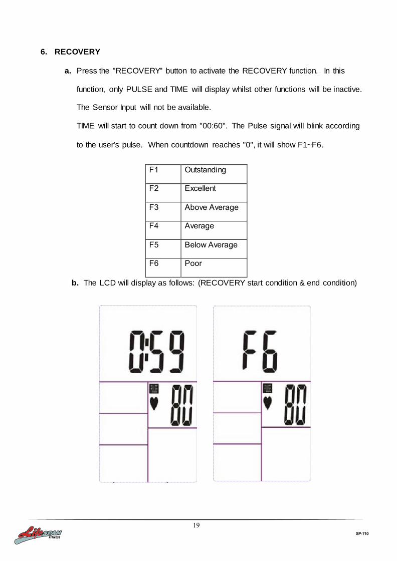
6. RECOVERY
a. Press the "RECOVERY" button to activate the RECOVERY function. In this
function, only PULSE and TIME will display whilst other functions will be inactive.
The Sensor Input will not be available.
TIME will start to count down from "00:60". The Pulse signal will blink according
to the user's pulse. When countdown reaches "0", it will show F1~F6.
F1 Outstanding
F2 Excellent
F3 Above Average
F4 Average
F5 Below Average
F6 Poor
b. The LCD will display as follows: (RECOVERY start condition & end condition)

20
SP-710
c. If the countdown to 00:00 is not completed and there is no pulse signal, F6 will
show.
d. If you press the RECOVERY button prior to the countdown reaching 00:00, this
will end the function and no result will show.
NOTE
1. After being inactive for 4 minutes, the main screen will turn off and will display the clock
automatically.
2. If the computer displays abnormally, please re-install the battery and try again.
Battery Spec: 1.5V UM-4 or AAA (2PCS).

21
SP-710
7. EXERCISE GUIDE
PLEASE NOTE: Before beginning any exercise program, consult your physician. This is important
especially if you are over the age of 45 or individuals with pre-existing health problems.
The pulse sensors are not medical devices. Various factors, including the user’s movement, may
affect the accuracy of heart rate readings. The pulse sensors are intended only as an exercise aid in
determining heart rate trends in general.
Exercising is great way to control your weight, improving your fitness and reduce the effect of aging and
stress. The key to success is to make exercise a regular and enjoyable part of your everyday life.
The condition of your heart and lungs and how efficient they are in delivering oxygen via your blood to your
muscles is an important factor to your fitness. Your muscles use this oxygen to provide enough energy for
daily activity. This is called aerobic activity. When you are fit, your heart will not have to work so hard. It will
pump a lot fewer times per minute, reducing the wear and tear of your heart.
So as you can see, the fitter you are, the healthier and greater you will feel.
Warm-up
Start each workout with 5 to 10 minutes of stretching and some light exercises. A proper warm-up increases
your body temperature, heart rate and circulation in preparation for exercise. Ease into your exercise.

22
SP-710
Training Zone Exercise
After warming up, increase the intensity to your desired exercise program. Be sure to maintain your intensity
for maximum performance. Breathe regularly and deeply as you exercise-never hold your breath.
Cool Down
Finish each workout with a light jog or walk for at least 1 minute. Then complete 5 to 10 minutes of
stretching to cool down. This will increase the flexibility of your muscles and will help prevent post -exercise
problems.
Workout Guidelines
TARGET ZONE
THIS IS HOW YOUR PULSE SHOULD BEHAVE DURING GENERAL FITNESS EXERCISE.
REMEMBER TO WARM UP AND COOL DOWN FOR A FEW MINUTES.
The most important factor here is the amount of effort you put in. The harder and longer you work, the more
calories you will burn. Effectively this is the same as if you were training to improve your fitness, the
difference is the goal.

23
SP-710
8. WARRANTY
AUSTRALIAN CONSUMER LAW
Many of our products come with a guarantee or warranty from the manufacturer. In addition, they come with
guarantees that cannot be excluded under the Australian Consumer Law. You are entitled to a replacement or refund for a major failure and compensation for any other reasonably foreseeable loss or damage. You are entitled to have the goods repaired or replaced if the goods fail to be of acceptable quality and the failure does not amount to a major failure. Full details of your consumer rights may be found at www.consumerlaw.gov.au
Please visit our website to view our full warranty terms and conditions:
http://www.lifespanfitness.com.au/warranty-repairs
Please email us through [email protected] for all warranty or support issues.
Warranty and Support:
Please email us at [email protected] for all warranty or support issues. For all warranty or support related enquiries an email must be sent first before contacting us via other means.

24
SP-710
Hand Pulse Technology Lifespan Fitness Spin Bikes come equipped with hand pulse sensors which are used to pick up tiny EKG/ECG
signals that run through the body when your heart beats. These electrical EKG/ECG signals are very small and
that they must be amplified 1000 times to make the signal useful for the computer to display your pulse.
To ensure proper operation:
- The user must maintain good, consistent contact on all four sensors
- The users skin cannot be too dry or too wet
Other factors that could affect the reading:
- Change of grip on the sensors (during slow pace cycling and up to sprinting)
- Tightening of hand muscles will produce small electrical signals
- Static electricity charges from the air or from moving on the spin bike
EKG/ECG Sensors may filter through actual EKG/ECG signals and “Noise” factors that may affect the reading.
This will cause the pulse reading to be delayed and will take longer to update the display as the heart rate
changes. Too much noise will create an incorrect reading. Medical conditions or having no electrical signal in the
hands are other factors that may affect pulse readings as well.
These are limitations of hand pulse technology and even the most expensive systems (which can cost upwards
of $3,000) used in hospitals have the same problems. The difference is that a patient in a hospital is not pedaling
on a spin bike.
To test if your hand pulse sensors are working up to specification, hold them while stationary, not pedaling, and
see if the reading is more in line with what you would expect. This will eliminate the movement and static
electricity factors. If your hands are dry, then wet them slightly (saliva works as a great conductor if this doesn’t
bother you).
For more information, please contact our Lifespan Technical Support Department
www.lifespanfitness.com.au