southern regional power committee -...
TRANSCRIPT


Special Meeting on PSS related issues held on 21.08.2015
SOUTHERN REGIONAL POWER COMMITTEE BENGALURU
Record Notes of Deliberations of the Meeting on PSS related issues held on 21st August 2015
A Meeting on PSS related issues was held at SRPC, Bengaluru on 21st August
2015. The List of participants is furnished at Annexure-I.
Background Note
Provision for PSS tuning was there in earlier IEGC also. The Enquiry Committee
for grid disturbances constituted by GoI had emphasized on tuning of PSS
(Recommendation 9.9.2). Para 1.4 of Meeting held on 11.03.2014 in MoP to discuss the
Task Force Report is reproduced below:
“Chairman, Task Force informed that the settings of the controllers of the Power
Electronics Devices (PEDs) were done at the time of commissioning of these devices and
were not very effective under the present conditions. It has been recommended by Task
Force that Tuning/re-tuning of Power Electronics Devices (like HVDC Controller, Static
VAR, Compensator etc.) and PSS should be done based on results of studies in the
present network scenarios and the exercise should be repeated every 3-4 years. Task
Force has also recommended that the review and study may be entrusted to independent
agency while retuning of controllers should be entrusted to respective suppliers under
suitable AMC or service contract. It was decided that Powergrid will submit the plan of
action to implement this recommendation and after examination by CEA, the exercise of
study and retuning would be completed by Powergrid in a shortest possible time”
Need for PSS tuning of all major generators had also been raised by SRLDC on a
number of occasions in the recent past keeping in view the sustained oscillations of high
mode and poor damping. In the 27th SRPC Meeting held on 12th May 2015, it was agreed
to constitute a group comprising Members from CTU, SRLDC, Generators & SRPC
Secretariat in respect of PSS tuning.

Special Meeting on PSS related issues held on 21.08.2015
Clause 5.2(k) of IEGC Regulation is reproduced below:
“All generating stations shall normally have their automatic voltage regulators
(AVRs) in operation. In particular, if a generating unit of over fifty (50) MW size is required
to be operated without its AVR in service, the RLDC shall be immediately intimated about
the reason and duration, and its permission obtained. Power System Stabilizers (PSS)
in AVRs of generating units (wherever provided), shall be got properly tuned by the
respective generating owner as per a plan prepared for the purpose by the CTU/RPC
from time to time. CTU/RPC will be allowed to carry out checking of PSS and further
tuning it, wherever considered necessary.”
CEA (Technical Standards for Connectivity to the Grid) Amendment Regulations,
2013 stipulates the following in respect of PSS:
“ Part II
Connectivity Standards applicable to the generating stations
A. Connectivity Standards applicable to the Generating Stations other than wind and generating stations using inverters
……………..
A1.For Generating stations which are connected on or after the date on which CEA (Technical Standards for Connectivity of the Grid) Regulation, 2007 became effective
( 1 ) The excitation system for every generating unit:-
…………………..
( c ) The Automatic Voltage Regulator of generator of 100 MW and above shall include Power System Stabilizer (PSS)
……………………
A2. For Generating stations which were already connected to the grid on the date on which CEA (Technical Standards for Connectivity of the Grid) Regulation, 2007 became effective
For all thermal generating unit having rated capacity of 200 MW and above and hydro units of having rated capacity of 100 MW and above, the following facilities would be provided at the time of renovation and modernization.
…………………..
( 2 ) Every generating unit of capacity having rated capacity of higher than 100 MW shall have Power System Stabilizer.

Special Meeting on PSS related issues held on 21.08.2015
……………………”
Summary of Deliberations in the Meeting
It was noted with concern that there was no representation from CTU even though
IEGC envisages role of CTU in PSS tuning. In the Meeting held in MoP cited
above, CTU had been entrusted the works relating to PSS tuning.
It was also noted that TANGEDCO, NTECL, NTPL, KGS, JSWEL, TPCL, NCCPL,
IL&FS & Coastal Energen had not sent their representatives to the Meeting which
was also a matter of concern. KKNPP vide letter dated 20th August 2015
(Annexure-II) had informed that they were not in a position to attend 1st Meeting
on PSS tuning. PSS testing/setting had been carried out on 07th June 2014 and
relevant pages of the test were enclosed.
Presentation made by SRLDC on LFO is at Annexure- III. SRLDC presentation on
Testing of PSS and Experience in NR is at Annexure- IV. Need for PSS tuning in
damping inter-area and local mode of oscillation was highlighted.
Presentation made by NTPC is at Annexure-V.
It was noted that PSS facility was not available in few of the units. In some of the
units it was not enabled / bypassed. PSS was set at default setting by their OEMs.
It was noted that Step Response Test had not been carried out by most of the
generators during last 2 years except NTPC.
On a query, NTPC informed that it was difficult to carry out Step Response Test in
AVR while it was easier in DVR.
Step Response Test is carried with PSS in disabled condition. Thereafter, the Step
Response Test is carried with PSS enabled state. Output curves of both Step
Responses are then compared to establish the effectiveness of damping provided
by PSS.

Special Meeting on PSS related issues held on 21.08.2015
‘NERC standard for PSS’ and extract from ‘ERCOT Nodal Operating Guide
regarding System Operation and Control Requirement’ is given at Annexure-VI &
VII respectively.
UPCL stated that they had the PSS facility and their OEM was requesting for data
on grid parameter for PSS tuning.
Recommendations finalized in the Meeting:
All utilities to furnish the data/information in respect of PSS as per enclosed format
(Annexure-VIII) by 30th September 2015. Step Response Test schedule (phased
manner) also needs to be furnished by 30th September 2015 to ensure that all the
eligible units are tested and tuned before 31st August 2016. Another Meeting (one
day before PCSC Meeting ) in October 2015 would be held to finalize further action
plan.
It was decided to constitute a group comprising of the members from NTPC, KPCL
(Hydro), UPCL, CTU, SRLDC and SRPC to analyze the date of PSS tuning
submitted by various generating stations and also the periodicity of PSS tuning.
Identified utilities were requested to submit the nominations for the PSS group by
30th September 2015.
PSS settings would be set to dampen mode with oscillations within the range of 0.2
Hz to 2 Hz. The above group would define the damping limits for monitoring
purpose.
NTPC suggested that Step Response Test for PID of AVR at no load was very
much essential before carrying out the retuning activity.
All generating units with capacity over 50 MW, for which PSS have not been tuned
or Step Response Test has not been carried out during last 24 months, should do
so within next 12 months and submit result of Step Response Test to
SRPC/SRLDC/CTU.

Special Meeting on PSS related issues held on 21.08.2015
If PSS has been tuned or Step Response Test has been carried out during last 24
months, the generating company would submit the results of Step Response Test
to SRPC/SRLDC/CTU within one month.
If results of Step Response Test indicate sufficient damping, generating company
would perform next Step Response Test after 3 years or at the time of major
overhaul of the unit, whichever is earlier.
Generating company would arrange for retuning of PSS, if Step Response Test
indicates insufficient damping or oscillations.
All new units with capacity over 50 MW must carry out PSS tuning before
declaration of Date of Commercial Operation (COD). A report along with model
parameters shall be submitted to CTU/SRLDC/SLDC/SRPC.
SRLDC will observe and analyze the change in the grid condition based on the
output of the PMUs and inform the concerned generating company if un-damped
oscillations beyond agreed pre-defined limits are observed. On receipt of the
information, the generating company would arrange for retuning of PSS within a
time frame of 3 months.
In some of the generating units it may not be feasible to tune PSS. Details of such
units (COD date, capacity, OEM, reasons as to why PSS cannot be tuned etc.)
would be furnished by the generating company. These would be discussed in
OCC/TCC/SRPC and if there is general agreement that PSS tuning was not
feasible, the matter would be taken up by generating company with Hon’ble CERC
for seeking exemption for those units.
PSS shall be kept in service (“On” or energized and performing as designed by the
manufacturer). PSS could be taken out under intimation to SLDC/SRLDC along
with technical justification i.e. for short duration of one week. Exemption beyond
one week needed to be taken up with Hon’ble CERC/SERC.

Special Meeting on PSS related issues held on 21.08.2015
Retuning of PSS could be covered in AMC/Service Contract preferably entrusted
to the respective supplier.
***


Annexure- III SRLDC Presentation on LFO

Monitoring and Analysis of Oscillations in Southern Regional Grid of India using
Synchrophasor data
2

Contents
• Introduction
• Low Frequency Oscillations
• Detection of LFO using Synchrophasors
• Case Study I
• Case Study II
• Case Study III
• Miscellaneous
• Conclusion
3

Introduction
• Synchrophasor pilot projects have been taken up in all regional grids that have enhanced wide area visualization.
• Dynamic behavior of power system can be viewed which was previously possible only through Disturbance Records.
4

Introduction – Complexity of grid
5

Introduction – Synchrophasor projects
6
Total no of PMUs - 63
Nos.
Region wise PMUs:
NR - 14 Nos
WR - 16 Nos
ER - 12 Nos
SR - 13 Nos
NER - 08 Nos

Low Frequency Oscillations
• Small signal instability is due to insufficient damping torque leading to LFO.
• Oscillatory modes that are well damped may get excited during any small disturbance.
• These oscillations may cause protective equipment to maloperate, fatigue to mechanical parts of generator and reduce transfer capability.
• Classified as Inter-area mode (0.1-1 Hz), local mode and intra-plant mode (1-2.5 Hz).
7

Detection of LFO using Synchrophasors
• System operators cannot detect LFO using SCADA due to the low refresh rate.
• Local modes were only seen as hunting in generators or through simulation studies.
• Phasor measurement units (PMU) that send time tagged data at a rate of 25-50 frames/sec enable operator to visualize the dynamics over a wide area.
• Tools and techniques are in development for the detection of analyzing various power system phenomenon including LFO.
8

Case Study I - Tripping of evacuating lines of generator
9
Line Trip Time
400 kV Vallur-NCTPS-1 02:43
400 kV Vallur-NCTPS-2 03:24
400 kV Vallur-Alamathy-1 03:58
400 kV Vallur-Alamathy-2 03:58
400 kV Vallur-KVPT-2 03:58
3:52 3:58
Unit Trip Time
NCTPS Unit 1 and 2 03:53
Vallur Unit 1 and 2 04:50
20-04-2014
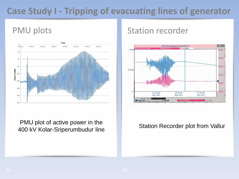
PMU plots
10 10
Station recorder
Case Study I - Tripping of evacuating lines of generator
PMU plot of active power in the
400 kV Kolar-Sriperumbudur line Station Recorder plot from Vallur

OMS Analysis
11 11
PSSE Studies
Case Study I - Tripping of evacuating lines of generator
OMS Engine results PSSE Study results

Case Study II – Spontaneous Oscillations
• Low frequency oscillations across the Indian Grid seen through PMU data in the early hours on 9th-12th Aug 2014.
• Hunting in several of the generating plant in Eastern, Western and Northeastern region.
• Oscillations were observed in HVDC power order and several transmission lines.
• Mode shapes and dominant mode had to be found to determine the likely epicenter.
• The mode spread through the national grid was found.
12

13 13
Case Study II – Spontaneous Oscillations

14 14
Case Study II – Spontaneous Oscillations
Dominant Mode frequency:
9-11th Aug - 0.75 Hz
12th Aug - 0.6 Hz
Coherent groups were obtained from
the OMS Analysis. ER and WR were in
phase with phase shift of -300 to 300.
Southern Region was almost in phase
opposition with that of ER region.

Case Study III – Equipment failure in Gen Station
• Spurious activation of overspeed limiting gear - causing variation in pressure in SV valve, hunting and subsequent oscillations.
• MW output varied between 20-120 MW for 29 secs.
• SPS signal was sent when rate of change of flow (due to the oscillations) went above the setting.
• Analysis showed oscillations with a frequency of 0.23 Hz and damping ratio varying from -5 % to 13 %.
15

PMU plots
16 16
PMU plots
Case Study III – Equipment failure in Gen Station
PMU plot of Raichur-Sholapur PMU plot of frequency
06-05-2014

OMS Analysis – Frequency
17 17
OMS Analysis – MW
Case Study III – Equipment failure in Gen Station
OMS Engine results OMS Engine results

Miscellaneous
• Local Modes of Oscillation Observed in Thrissur on 26th October 2014.
• None of the generating stations around Thrissur including hydro and thermal stations reported any hunting.
• OMS analysis revealed that the frequency was 1.1 Hz and was not observed beyond Tirunelveli (Hence local mode) as can be seen from the mode energy comparison.


Summary of oscillation modes in SR
Mode frequency Damping Nature Type of Oscillation Particular incident
0.2-0.25 Hz Generally stable with good damping ratio
Inter-area mode Tripping of units such as Vallur, Hunting in Kothagudem Units
0.7 Hz Very low damping (negative too)
Inter-area mode Generator connected by long line (Vallur)
0.58-0.75 Hz Low damping ratio Inter-area mode Spontaneous in nature due to low load response
1.1-1.2 Hz Low damping Local Mode Local modes in and around Thrissur

Conclusion
• From the case studies illustrated we could see how PMU data have enabled in detecting LFO, and also provide an alert to system operator.
• Customized applications of synchrophasors in the operation as well as planning domain are being developed for further exploitation of the technology.
• Make and online application for detecting LFO and determine the mode shape and energy real time.
• Detect dynamic behavior intuitively through their patterns and help alert the operator.
22

Annexure- IV SRLDC presentation(PSS Testing & NR experience)

Power System Stabilizer Testing

Indian Scenario
In Section 5.2.(k) of the Indian Electricity Grid Code (IEGC)
• “All generating units shall normally have their automatic voltage regulators (AVRs) in operation. In particular, if a generating unit of over fifty (50) MW size is required to be operated without its AVR in service, the RLDC shall be immediately intimated about the reason and duration, and its permission obtained. Power System Stabilizers (PSS) in AVRs of generating units (wherever provided), shall be got properly tuned by the respective generating unit owner as per a plan prepared for the purpose by the CTU/RPC from time to time. CTU /RPC will be allowed to carry out checking of PSS and further tuning it, wherever considered necessary”

Experience of Other Region NORTHERN REGION

Initial Steps
• A group comprising one member each from NRPC,CTU,NRLDC,
NTPC & BHEL was formed in 27th TCC/30th NRPC meeting held
on Feb 2014.
• Two meetings on 16th July 2014 & 05th Sept 2014 were held to
analyse the data submitted by various generating stations & also
the periodicity of PSS tuning.
• Continuous follow up on the recommendations given by the
group is taken up in NRPC OCC/TCC meetings.

Discussions held
• BHEL: PSS might require to be re-tuned due to network changes in vicinity of generator
• NTPC: PSS tuning is done in the presence of OEM at the time of Capital overhaul, which is carried out periodically once in a every 3 years.
• NHPC: In case of units with Digital AVR, Step Response Test can be carried out using in-house expertise and presence of OEM may not be required
• NRPC: No shutdown is required for conducting Step Response Test

Recommendations of the Group
• All generating units with capacity over 50 MW would perform Step Response Test for their generating units every year and will submit result to NRPC, NRLDC and CTU
• The generating units for which PSS has not been tuned in last three years will carry out Step Response Test within six month and will submit report to NRPC,NRLDC and CTU.
• NRLDC will observe and analyze output of PMUs and will inform the generating Company concerned if oscillations are observed
• Generating Companies would perform PSS tuning if Step Response Test indicates insufficient damping or oscillations are observed by NRLDC

Basics of PSS

Excitation system with AVR and PSS
Basic Function of PSS :
• To add damping to the generator rotor oscillations by controlling its excitation using
auxiliary stabilizing signals.
• Stabilizer produces a component of electrical torque in phase with rotor speed
deviations for damping

PSS-Components
• Gain
It should be computed at the frequency of oscillations and should
be enough to make damping co-efficient positive
Damping increases with an increase in gain up to a point
Delta-Omega stabilizer: Due to the effect of the torsional filter, the
stability of the "exciter mode" becomes an overriding consideration
Delta-P-Omega stabilizer: Exciter mode stability is not a problem,
and a considerably higher value of gain is acceptable

PSS-Components
• Stabilizing Signal Washout
High pass filter which blocks the interference of PSS during regular function
of exciter during steady state operation
Time constant TW should be high enough to allow signals associated with
oscillations in rotor speed to pass unchanged
For systems with dominant inter area oscillations set TW to about 10s
TW of less than 5s results in significant phase lead at low frequencies
associated with inter area oscillations

PSS-Components
• Lead – Lag Compensator
It provides appropriate phase-lead to compensate for the phase lag
between exciter input and generator electrical torque.
In practice two or more first order blocks may be used to achieve the
desired phase lead
For systems with dominant inter area oscillations ,use one of the phase
compensation blocks to provide phase lag at low frequencies

Classification
Based on input given to PSS:
Speed-based
Frequency- based
Power-based
Integral of Accelerating Power based
Single input
Dual input

Single input PSS model- Speed based
The limitation of this type of stabilizer is the need to use a torsional filter as direct
measurement of shaft speed is used.
Limit on the maximum stabilizer gain

Dual Input– Accelerating Power based
HIGH PASS
FILTERS
HIGH PASS
FILTERS
SPEED
POWER
RAMP
TRACKING
FILTER
GAIN & PHASE
LEAD
• No need for a torsional filter in main stabilizing path
• Higher stabilizer gain
Integral of Pa

PSS Commissioning & Testing
• Suitability of tuning of any PSS is checked in both the time and frequency domains.
• Test procedure in time domain – Small voltage step change is injected into the AVR voltage reference block
• Test procedure in frequency domain – 200mHz – 3 Hz, random noise injection is made to the AVR voltage reference
• Comparison is made between performance ‘with’ and ‘without’ the PSS in service
• Stability of PSS gain setting is also assessed by increasing the gain in stages to 3 times the proposed setting. This increase is carried out gradually while monitoring the generator for any signs of instability

Parameters to be recorded
• Terminal Voltage
• Excitation current
• Active Power Output of the Unit
• Reactive Power Output of the Unit
• PSS output

International Practices

WECC:
• Generator Operators shall have PSS in service 98% of all
operating hours for synchronous generators equipped with
PSS
• For excluding PSS out of service hours, generator operators
must provide date of outage & submit the supporting
documents that applies.
• Generators Operators shall provide quarterly reports to the
compliance monitor

ERCOT :
• The Generation Resource(>10 MW) shall establish PSS settings
to dampen modes with oscillations within the range of 0.2 Hz to 2
Hz.
• At least every five years, Generation Entities shall conduct
performance tests on PSS settings or verify PSS performance
based on operational data. If PSS equipment characteristics are
modified, the Generation Entity shall conduct a performance test
within 30 days of the modification

Test Results KARCHAM WANGTOO : 4 x 250 MW
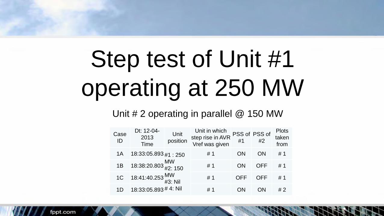
Step test of Unit #1
operating at 250 MW Unit # 2 operating in parallel @ 150 MW
Case
ID
Dt: 12-04-
2013
Time
Unit
position
Unit in which
step rise in AVR
Vref was given
PSS of
#1 PSS of
#2
Plots
taken
from
1A 18:33:05.893 #1 : 250
MW
#2: 150
MW
#3: Nil
# 4: Nil
# 1 ON ON # 1
1B 18:38:20.803 # 1 ON OFF # 1
1C 18:41:40.253 # 1 OFF OFF # 1
1D 18:33:05.893 # 1 ON ON # 2

Response of Unit # 1
Step input on # 1, PSS-1 & PSS-2 OFF
Active Power
Reactive Power Output
Field Current
PSS contribution
Terminal Voltage

Response of Unit # 1
Step input on #1, PSS-1 ON, PSS-2 OFF

Response of Unit # 1
Step input on # 1, PSS-1 & PSS-2 both ON
Field Current
Active Power
Terminal Voltage
Reactive Power Output
PSS contribution

Response of Unit # 2
Step input on # 1, PSS-1 & PSS-2 both ON

Response of Wangtoo Unit-2 and 4 (Total 550
MW) when 400 kV Wangtoo-Abdullapur-1
carrying 275 MW was opened
400 kV Wangtoo-Jhakri D/C line was open
and Baspa HEP generation was Nil
Case ID Dt: 12-04-
2013
Time
Switching
operation of 400
kV Wangtoo-
Abdullapur-I
PSS of
#1 PSS of
#2
Plots
taken
from
P 11:46:38.157
#1: Nil
#2: 275
MW
#3: Nil
#4: 275
MW
Close to Open ON ON #2
Q #4
R 11:47:46.878 Open to Close ON ON
#2
S #4
T 11:56:28.766 Close to Open OFF OFF
#2
U #4
V 11:57:57.699 Open to Close OFF OFF
#2
W #4

Response of Unit # 2
PSS-2 OFF, PSS-4 OFF

Response of Unit # 2
PSS-2 ON, PSS-4 ON

Response of Unit # 4
PSS-2 OFF, PSS-4 OFF

Response of Unit # 4
PSS-2 ON, PSS-4 ON

As observed from PMU data at NRLDC

Test Results RAJPURA THERMAL POWER PLANT : 2 x 700 MW


Way forward for SR
• All generating units (>50 MW) shall inform SRPC/SRLDC when
last PSS tuning was done.
• SLDC may coordinate with the state generating stations (>50
MW) regarding the PSS tuning.
• The generating units for which PSS has not been tuned in last
three years will plan the step response test in coordination with
their OEM and inform SRPC/CTU regarding the same.

Thank You

Annexure- V
NPTC Presentation

Static Excitation
DC AC
Controlled Rectifier
Main Generator

Brushless Excitation
Main Generator
Diode Bridge
(rotating)
Field
Winding AC generator
R R
R
S
S S S
N
S
R
Permanent
Magnet
Generator
R: Rotating Member
S: Stationary Member
Control Signals
From Regulator


Delta
Power
Increased
Excitation
X: Line Reactance
V: Bus Voltage
E: Gen Voltage
P: Power
Power Vs Delta Curve

POWER SYSTEM STABILITY

Power System Instability: Loss of Synchronism
A M/c loses synchronism with the rest of the system, its
Rotor runs at a higher or lower speed w.r. t system frequency:
Causes a) Failure of or Weak excitation system
or b) delayed system fault clearances
or c) transient fault / change in system condition
or d) Failure of governor.
Slip betwn stator field (system freq) & rotor field results in
large fluctuations in power o/p, current & Voltages.
The ability of a PS to maintain stability depends to a large
extent on the control available on the system to damp the
electromechanical oscillations.

DTe = TS Dd + TD Dw
Synchronizing + Damping Torque
Change in Elect
Torque following a
distrurbance =
SSS (Small Signal / Steady State Stability): depends
on a) Initial operating condition, b) strength of the
transmission system, c) Excitation control etc.
With automatic
control
SSS Without automatic
control
Classical Steady
State Stability
Dynamic Stability
Ability of PS to maintain synchronism after
severe disturbance.
Transient
Stability

Dd Dw
DTS
o t Dd
Stable
Positive TS
Positive TD
DTD
DTe
o t Dd
Non Oscillatory
Instability
Negative TS
Positive TD
DTD
DTe
Dd
DTS
Dw
Response of Steady State Stability (small signal stability)
with Manual Excitation (Efd constant)
Lack of Synchronizing torque cause an aperiodic drift in d

Dd Dw
DTS
o t Dd
Stable
Positive TS
Positive TD
DTD
DTe
Dd
Response of Steady State Stability (small signal stability)
with Excitation on AVR(Efd variable)
o t
Dd
Oscillatory
Instability
Positive TS
Negative TD DTD
DTe
DTS
Dw
Lack of sufficient damping torque cause oscillatory instability.

In today’s power system, SSS is largely a problem of
insufficient damping of oscillation. Oscillations of
concern:
Local mode (M/c –system mode): Unit swinging w.r.t
rest of the system.
Interarea modes: Two or more groups are swinging.
Control modes: Generating unit with other control.
Poorly tuned exciters, speed governors, HVDC
converters, SVC are the causes of such mode of
instability.
Torsional modes: SSO- TG shaft system rotational
components. Causes excitation control, speed
governor, HVDC controllers, Series Capacitor
compensated lines.

Multi-machine Systems-Relative motion
Many Swing Modes (0.2 – 2 Hz)
Intra-plant
Inter-area
local

0.5 1.0 1.5 2.0 2.5 3.0 0
Time in sec
d
Transient Stability:
Stable
First Swing
instability: poor Ts
Stable in First Swing but becomes
unstable due to growing
oscillation in post fault condition
which may have poor SSS

Transient stability:
Generator will be transiently stable on the first swing: If the retarding
torque after the fault clearing is sufficient enough to make up for the
acceleration during the fault and the generator moves back to a stable
operating point.
Stability depends on :
1) Excitation controllers
2) Fault clearing time
3) Power angle of the transmission system at the time of fault
4) Severity of disturbances
Fast excitation system can improve Transient Stability.
Small Signal Stability:
Undamped MW oscillation after a disturbances.
Excitation system has the potential cause SS instability.
Compensation from PSS is the solution.

SEE AVR Block Diagram

AVR Block Diagram - Example
(1+sT1)
(1+sT2)
S Vref
Measured Terminal
Voltage
+
-
+
Stabilizing / Limiting Signals
To
Thyristor
Bridge
K
CONTROLLER
(example)
S
+ +
Stabilizing / Limiting Signals
(alternative summing point)

AVR
STATIC EXCITATION SYSTEM
_

Structure of PSS: PSS-2B

Power system stabiliser
• Stabilisation signal =f(∆Pe, ∆f)
∆Pe = change in Electric power
∆f = change in frequency
• The slip signal ∆f follows ∆Pe with a phase delayed by 90 Deg.
• A good damping is obtained if electrical power is varied in phase with load angle
• By applying proper weighting factors( k1,k2) and then adding together the signals ∆Pe and ∆f , an overall stabilising signal can be produced.
∂ ∆Pe
∆f
Resultant
stalising signal k1
k2

Power system stabilizer
• The optimum weighting factors k1 and k2 for a synchronous generator working to a power network depend on its operating point at any moment and the external reactance of the network.
• Selection of a compromise setting is good enough to attain stability in all operating points and for all expected external reactances.

Power system stabiliser
• The PSS stabilisation signal is imposed on AVR only if all the following prequisites are met • Generator on line
• Generator power output >30%
• Generator voltage > 90%

Slip Stabilizing ADAPTER
• The slip stabilizing signal is formed from the sum of generator active power signal and the generator frequency signal. The amplification and mixing ratio for the two signals are referred to as the weighting.
• The stability of the synchronous m/c operating on a network depends on operating point of the m/c and the expected external reactance Xe of the network.
• If the network conditions do not permit the use of compromise setting the PSS adaptor provides a solution

Xe Identification
• The complete operating range of the m/c is divided into six operating sub ranges
• The weighting factors are determined for the six sub ranges and for three different (expected) external reactances Xe
• Total 18 operating sub ranges under consideration
• For each sub range the optimum weighting factors are determined and are stored in table of parameters. The resultant signal is then issued to regulator.

Xe Identification
xe1
xe2
xe3
p1
p2
q1 q2 q3

Xe Identification
• The PSS adapter assess the operating point of the machine and the instantaneous value of external reactance.
• Once this has been done, the corresponding weighting factors are read from the stored table and are transferred to the voltage regulator.

Step Response Test


Frequency Response Test

1920
1930
1940
1950
1960
1970
1980
1990
2000
2010
2020
14.9 15.9 16.9 17.9 18.9 19.9 20.9 21.9
t, с
P, МВтоптимальная настройка
PSS на всех генераторах отключены
оптимальная настройка, PSS генератораBHEL отключен
Character of damping of large post-accident oscillations at emergency
outage of one circuit of Overhead line-765 kV SIPAT-SEONI (Scheme 1 →
Scheme 5). Conditions 1. The equivalent JSC Electrosila’s generator
(РgΣ=1980 MW, QgΣ=1230 MV*A)


Name of the Utility:
Status as on:
Name of
the
Station
Unit
No.
Type(Hydro/
Coal/Gas/Die
sel/Nuclear
IC in
MW
Date of
Commer
cial
Operatio
n(CoD)
AVR or
DVR
PSS
Availabili
ty
(Yes/No)
PSS in
service
or not
Whether
exempted
by ERC
Date of
last Step
Response
Test
Date of Step
Response Test
report furnished to
CTU/SRLDC/SRPC
Date of next
Step Response
Test as per
Generator
Date of next
Step response
Test (in case
insufficient
damping)
Name of
AMC/OEM
for PSS
Status of PSS Tuning of generators of capapcity above 50 MWAnnexure- VIII