south portland supersedes july 8, 2011 - maine€¦ · july 28, 2011 supersedes july 8, 2011 1....
TRANSCRIPT

South Portland WIN 011062.00
July 28, 2011 Supersedes July 8, 2011
SPECIAL PROVISION
SECTION 652 PORTABLE CHANGEABLE MESSAGE SIGN
Description This work consists of furnishing new, trailer-mounted portable changeable message signs (signs) with cell modems and providing sign-related testing, up to 20 hours of class room training, spare parts, control software, 12-months of technical assistance, and warranty. General Project Summary The manufacturer shall deliver the signs to the Fleet Services Building, 109 Capital Street, in Augusta. Delivery driver must call (207) 287-2677 to arrange delivery between the hours of 8am and 4pm. Where, the manufacturer shall test each sign (and certain spare parts) in the presence of Department personnel and the installation contractor. The manufacturer shall also train the installation contractor’s staff and Department personnel in the proper installation and set-up of the signs. Any deviation from the following minimum specifications must be pre-approved by Cliff Curtis, Ron Cote, and Peter Virgin of the Department. The signs will be installed as shown on the plans or as directed by the resident. When the first sign is installed, the sign manufacturer shall supervise the installation contractor’s work and shall conduct additional training if needed, to ensure that the trainees are competent to install the remaining signs. The manufacturer shall install sign control software on computers supplied by the Department, test the software, and train Department personnel in its use. Manufacturer Qualifications The sign must be made by a manufacturer meeting the following qualifications:
• Little risk of financial problems that could impair the manufacturer’s ability to provide warranty service, technical support, and spare parts over the next year.
• A record of satisfied customers for products equivalent to those to be furnished under this contract.
• Ability to produce products in compliance with the National Transportation Communications for ITS Protocol (NTCIP).
Required Submittals Five copies of the following items shall be submitted.
a. As a condition of award Demonstrate the manufacturer meets the requirements of the above.
Page 1 of 22

South Portland WIN 011062.00
July 28, 2011 Supersedes July 8, 2011
1. Dunn & Bradstreet’s “Comprehensive Insight Plus” report on the manufacturer’s financial condition. If the manufacturer is a subsidiary, provide the report for the parent. 2. Names, titles, and telephone numbers of individuals at five or more transportation agencies that have purchased the manufacturer’s trailer-mounted LED signs with NTCIP-enabled central control software. Do not include customers who have had the products less than six months. 3. Letter from an independent testing agency certifying that the manufacturer’s signs are compliant with NTCIP 1203. The signs and software subjected to the independent test need not be identical to those proposed for this project.
b. Prior to shipping any signs Each of these items must be revised until found acceptable by the Department.
1. Shop drawings and descriptive literature demonstrating that the signs meet these specifications. 2. Test report and certification by an independent testing agency that the sign meets the environmental requirements of NEMA TS 4, Hardware Standards for Changeable Message Signs (DMS) with NTCIP Requirements. The test must have been performed on sample components that are essentially identical to those provided in this project. 3. Certification by an independent testing agency or a professional engineer registered in Maine that the sign meets the structural integrity requirements of NEMA TS 4. The certification need only cover those aspects of structural integrity for which TS 4 requires certification. 4. Calculations demonstrating that the sign meets the battery capacity and solar recharging requirements of below, as well as the recharging requirement of Paragraph 3.3.5.3 of NEMA TS 4. For solar recharging, take into account the azimuth and tilt of the panels as they will be mounted. The panels must be tiltable and rotatable independent of the message board. 5. (2) Copies of the user manual for the central software. 6. (2) copies of manuals for the installation, operation, and maintenance of the signs. 7. A proposed plan for testing the signs, software, and spare parts at the time of delivery. 8. Resumes demonstrating the qualifications of the individuals who will train the installation contractor and Department staff.
Page 2 of 22

South Portland WIN 011062.00
July 28, 2011 Supersedes July 8, 2011
9. An outline of the proposed training activities with the estimated duration of each activity.
c. With the Signs
1. A CD containing the management information bases (MIBs) and electronic copies of the manuals and drawings provided earlier. The MIBs shall be ASCII files in Abstract Syntax Notation 1 (ASN.1) format. The supported range shall be indicated in ASN.1 format in the SYNTAX field of the associated OBJECT TYPE macro for devices that do not support the full range of any object within a standard MIB module. The manuals and drawings shall be in Acrobat or Word. The manufacturer shall allow the use of this documentation by any party authorized by the Department for systems integration purposes.
2. Maine uses a product name Vanguard for the control of other signs. A CD containing all necessary Font and Configuration files shall be provided and installed at the time the manufacturers software is installed.
3. Warranty covering the signs for the manufacturer’s standard warranty period, but not less than one year.
Conformance Testing of Display The manufacturer is not required to provide independent certification that the display meets the requirements in Section 5 of NEMA TS 4. However if, after inspecting the signs, the Department believes that the display properties do not fully comply with TS 4 and these specifications, then the manufacturer must either remedy the defects or present third party certification that the signs are in compliance. Portable Sign The sign shall consist of an all-LED (light emitting diode) matrix message board, support post, power system, and a controller assembly, all mounted on a heavy duty, towable trailer. The sign shall conform to NEMA TS 4, except for requirements of NEMA TS 4 that conflict with the requirements in this specification. General
a. Finish All exterior surfaces except the sign face shall be cleaned, primed and finished with two coats of Highway Safety Orange. An exception is the border around the display, which shall be black. The finish shall be either polyester powdercoat or baked enamel.
b. Wiring All wiring shall be inaccessible to vandals. Connections to power and telephone service supplied by others shall be via wires enclosed in liquid-tight flexible metal conduit, so the sign must have provision for connecting such conduit to the sign. All wiring and connections shall be of sufficient size to support all maximum currents continuously. (Including all pixels at maximum brightness.)
Page 3 of 22

South Portland WIN 011062.00
July 28, 2011 Supersedes July 8, 2011
c. Labeling All terminals and connections shall be clearly labeled. Labels shall be permanent, waterproof and machine-printed.
Message Board
a. Dimensions The display shall be a matrix of LED pixels approximately six feet high by 12 feet wide. Center-to-center pixel spacing shall be the same horizontally and vertically and shall be 2.6 inches or less. If the spacing is 2.6 inches, the display shall be at least 50 pixels wide and 27 pixels high. If the spacing is less, the number of pixels shall be proportionally larger. The sign shall be capable of displaying three lines of 18” high characters. b. Finish The inside of the display enclosure shall be painted black to facilitate heat dissipation. c. Display Modules The display shall be composed of at least ten display modules that can quickly be replaced in the field. They must be designed so they cannot warp. d. Glazing If the display modules are not weatherproof, they shall be protected by a watertight sheet of UV-protected acrylic or polycarbonate. e. LEDs The LEDs shall be amber and have a viewing angle of 30 degrees in the horizontal plane. That is, brightness at 15 degrees off axis shall be at least 50 percent of the on-axis brightness. f. Enclosure The enclosure shall be made of aluminum with aluminum and/or stainless steel fasteners.
g. Brightness When all pixels are illuminated at maximum brightness, the display shall have an on-axis luminance intensity of at least 3,720 candelas per square meter. The sign shall have an automatic intensity control feature in order to keep the LED lamp matrix intensity constant with a reduction in voltage. h. Sighting Device The housing shall include a sighting device to facilitate proper directional alignment of the message board. This device shall be securely mounted so that a 20 pound force in any direct will not misalign the sighting device.
Support Post The message board shall be mounted on a mast that is raised and lowered by an electrically powered hydraulic pump (with attached fluid reservoir).
a. Backup Pump The hydraulic system shall include an auxiliary manual pump with release for emergency use.
Page 4 of 22

South Portland WIN 011062.00
July 28, 2011 Supersedes July 8, 2011
b, Rotation When fully raised in the display position, the message board shall be able to rotate so the sign can be aimed at traffic. Solar panels must be rotatable and tiltable independently from the sign for maximum solar exposure. c. Locking Mechanisms The sign’s rotation-locking device shall be independent from the sign’s raise/lower-locking device Such device will be secure enough to prevent turning with 50 mph wind gusts. d. Protection The hydraulic system shall be inside a locked housing.
Power System The sign shall be powered by batteries that are recharged by 120 volt AC power when available and by solar power at other times.
a. Batteries The batteries must be available from multiple manufacturers. The number and type of batteries shall be sufficient to operate a display of 3 full lines of “X”s for 240 hours continuously with no recharging and no solar assist. b. Recharging During recharging of low batteries from 120-volt power, the sign shall operate normally. Power control circuitry shall protect the batteries from overcharging by the 120-volt and solar chargers. It shall also protect the all components from damage in the event of a short circuit, overload, or similar problem. It shall disconnect the load from the batteries when further discharging could damage the batteries. A voltmeter and ammeter shall be included to monitor the condition of the batteries and charging system. The 120 Volt battery charger shall include a separate ammeter for monitoring the charging process. c. Automatic Sensing of 120-Volt Power The system shall automatically switch between solar and 120-volt power (when available) for battery charging with no operator intervention. d. Operation without Batteries If the batteries have been disconnected, the sign and controller shall operate using 120 VAC. e. Solar Recharging The solar charging system shall produce more power in a 2 hour solar day than the sign needs to display a 3-line message (“X”’s) continuously for 24 hours. The solar panels shall be mounted so the panels can be rotated independently from the display for 360 degrees; In addition at the same time, the panels can be tilted from flat to 30 degrees from vertical. This structure shall be rugged enough to withstand 50 mph wind gusts from any direction while tilted.
Controller Assembly
Page 5 of 22
South Portland WIN 011062.00
July 28, 2011 Supersedes July 8, 2011
a. Control Architecture The sign shall support both types of control architecture described in Section 8.10 of TS 4. The controller shall be able to store at least 30 messages in non-volatile memory.
b. Fonts Section 5.6 of TS 4 does not apply to this sign. The controller shall be capable of storing at least four fonts in memory and shall be shipped with at least two fonts in memory. The user shall be able to create at least two additional fonts, download them to the controller, and store them there.
Both fonts shall be 18 inches high. One shall be comparable to that shown in Figure 7-1 of Federal Highway Administration publication # FHWA-TS-90-043. The other shall be a similar, compressed font. Both fonts shall include:
▪ All upper case letters,
▪ The following punctuation marks . , / ? ‘ : and “.
▪ All numerals 0 to 9,
▪ The following special characters #& * +< > c. Alarms The sign controller shall automatically notify the central sign control computer when the batteries are low.
Communication Section 8.7 of TS 4 does not apply to this sign. All communication with the sign controller shall use the latest recommended NTCIP standards at the time of bidding.
a. Communication Ports The controller shall have at least two communication ports that can be used for remote control. The controller shall accept commands via either port and respond via the same port that received the command, so that each port automatically functions as a backup communication link for the other port and include cell phone modems for Fairpoint, GPS and web server service.
• One port shall be equipped with an internal cellular modem. It shall operate in
accordance with the latest version of NTCIP 2103, Point-to-Point Protocol over RS-232 Subnetwork Profile. All Challenge Handshake Authentication Protocol (CHAP) secrets shall be user configurable via the CHAP Secret Table. This modem shall be a SierraWireless Pinpoint X modem for Fairpoint cellular service; The antenna installation shall also include a GPS antenna connected directly to the cellular modem The Department will supply the SIM card for the modem.
• The other port shall be an RJ-45 Ethernet port, which may be used for a wireless data
communication service. The Ethernet port shall also be suitable for connecting a notebook computer for local control and maintenance. It shall operate in accordance with the latest version of NTCIP 2104, Ethernet Subnetwork Profile. The medium shall be 10Base-T.
Page 6 of 22
South Portland WIN 011062.00
July 28, 2011 Supersedes July 8, 2011
b. Cellular Antenna An antenna suitable for cellular telephone or data service shall be installed on top of the message board. Install the antenna in a way that does not permit water to enter the message board. A 50 ohm coaxial cable, 100 percent shielded and designed for outdoor use, shall run from the antenna to the controller compartment. The cable may not pass through the top of the compartment and the hole where the cable enters must be sealed watertight. Immediately upon entering the controller compartment, the cable shall terminate on a grounded lightning protector. The antenna shall be omnidirectional, designed for both the 806-894 MHz range and the 1850-1990 MHz range. It shall have a built-in ground plane and vertical polarization. The antenna gain shall be at least 5 dBi. The GPS antenna for the cellular modem may be included in this antenna. c. Information Level Standards
1. Global Objects. The sign shall support the following objects defined in NTCIP 1201, Global Object Definitions:
• All objects in the Global Configuration Node. • The following objects in the Global Time Management Node: globalTime;
globalDaylightSaving; maxTimeBaseScheduleEntries; timeBaseSchedule-Table; maxDayPlans; maxDayPlanEvents; timeBaseDayPlanTable.
• All objects in the Report Parameters Node. The module table required by Clause 2.2.3 of NTCIP 1201 shall contain at least one row with moduleType equal to 3 (software). 2. Changeable Message Sign Objects At least the following objects, if defined in NTCIP 1203
♦ Sign Configuration and Capability Objects
▪ dmsSignAccess ▪ dmsSignType ▪ dmsSignHeight ▪ dmsSignWidth ▪ dmsSignTechnology ▪ vmsCharacterHeightPixels ▪ vmsCharacterWidthPixels ▪ vmsSignHeightPixels ▪ vmsSignWidthPixels ▪ vmsHorizontalPitch ▪ vmsVerticalPitch
Page 7 of 22

South Portland WIN 011062.00
July 28, 2011 Supersedes July 8, 2011
▪ vmsMaxNumberPages ▪ vmsMaxMultiStringLength
♦ Font Objects
▪ numFonts ▪ fontTable and subsidiary objects ▪ maxFontCharacters ▪ characterTable and subsidiary objects ▪ fontMaxCharacterSize
♦ MULTI Configuration Objects
▪ defaultFlashOn ▪ defaultFlashOff ▪ defaultFont ▪ defaultJustificationLine ▪ defaultJustificationPage ▪ defaultPageOnTime ▪ defaultPageOffTime ▪ defaultCharacterSet ▪ dmsColorScheme ▪ dmsSupportedMultiTags
♦ Message Objects
▪ messageIDCode ▪ messageActivationCode ▪ dmsNumPermanentMsg ▪ dmsNumChangeableMsg ▪ dmsMaxChangeableMsg ▪ dmsFreeChangeableMemory ▪ dmsNumVolatileMsg ▪ dmsMaxVolatileMsg ▪ dmsFreeVolatileMemory ▪ dmsMessageTable and subsidiary objects ▪ dmsValidateMessageError
♦ Sign Control Objects
▪ dmsControlMode ▪ dmsSWReset ▪ dmsActivateMessage ▪ dmsMessageTimeRemaining ▪ dmsMsgTableSource ▪ dmsMsgRequesterID
Page 8 of 22
South Portland WIN 011062.00
July 28, 2011 Supersedes July 8, 2011
▪ dmsMsgSourceMode ▪ dmsShortPowerRecoveryMessage ▪ dmsLongPowerRecoveryMessage ▪ dmsShortPowerLossTime ▪ dmsResetMessage ▪ dmsCommunicationLossMessage ▪ dmsTimeCommLoss ▪ dmsPowerLossMessage ▪ dmsEdDurationMessage ▪ dmsActivateMsgError ▪ dmsMultiSyntaxError ▪ dmsMultiSyntaxErrorPosition ▪ dmsMultiOtherErrorDescription ▪ dmsActivateMessageState
♦ Brightness Objects
▪ dmsIllumControl ▪ dmsIllumMaxPhotocellLevel ▪ dmsIllumPhotocellLevelStatus ▪ dmsIllumManLevel ▪ dmsIllumBrightnessValues ▪ dmsIllumBrightnessValuesError ▪ dmsIllumLightOutputStatus
♦ Scheduling Action Objects
▪ numActionTableEntries ▪ dmsActionTable and subsidiary objects
♦ Sign Status Objects, to the extent supported by the sign hardware.
▪ statMultiFieldRows ▪ statMultiFieldTable and subsidiary objects ▪ watchdogFailureCount ▪ dmsStatDoorOpen ▪ shortErrorStatus ▪ controllerErrorStatus ▪ dmsPowerStatusMap ▪ dmsPowerNumRows ▪ dmsPowerStatusTable and subsidiary objects ▪ fanFailures ▪ pixelFailureTableNumRows ▪ pixelFailureTable and subsidiary objects
Page 9 of 22
South Portland WIN 011062.00
July 28, 2011 Supersedes July 8, 2011
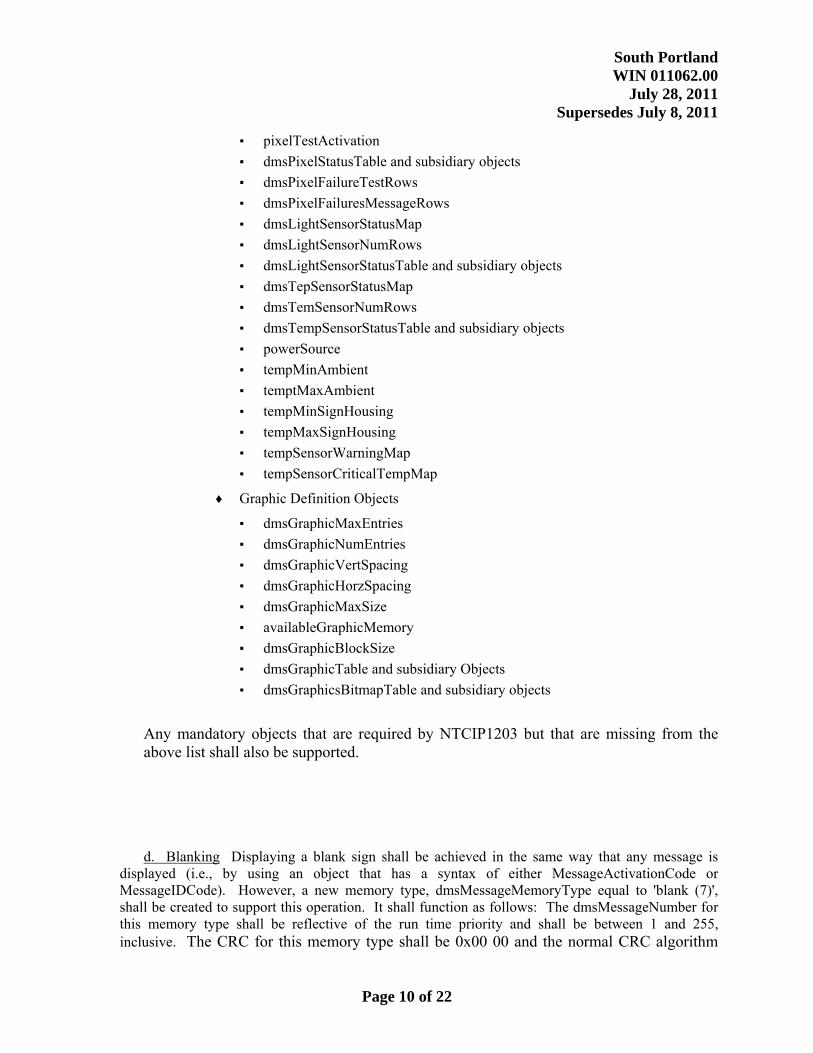
▪ pixelTestActivation ▪ dmsPixelStatusTable and subsidiary objects ▪ dmsPixelFailureTestRows ▪ dmsPixelFailuresMessageRows ▪ dmsLightSensorStatusMap ▪ dmsLightSensorNumRows ▪ dmsLightSensorStatusTable and subsidiary objects ▪ dmsTepSensorStatusMap ▪ dmsTemSensorNumRows ▪ dmsTempSensorStatusTable and subsidiary objects ▪ powerSource ▪ tempMinAmbient ▪ temptMaxAmbient ▪ tempMinSignHousing ▪ tempMaxSignHousing ▪ tempSensorWarningMap ▪ tempSensorCriticalTempMap
♦ Graphic Definition Objects
▪ dmsGraphicMaxEntries ▪ dmsGraphicNumEntries ▪ dmsGraphicVertSpacing ▪ dmsGraphicHorzSpacing ▪ dmsGraphicMaxSize ▪ availableGraphicMemory ▪ dmsGraphicBlockSize ▪ dmsGraphicTable and subsidiary Objects ▪ dmsGraphicsBitmapTable and subsidiary objects
Any mandatory objects that are required by NTCIP1203 but that are missing from the above list shall also be supported.
d. Blanking Displaying a blank sign shall be achieved in the same way that any message is displayed (i.e., by using an object that has a syntax of either MessageActivationCode or MessageIDCode). However, a new memory type, dmsMessageMemoryType equal to 'blank (7)', shall be created to support this operation. It shall function as follows: The dmsMessageNumber for this memory type shall be reflective of the run time priority and shall be between 1 and 255, inclusive. The CRC for this memory type shall be 0x00 00 and the normal CRC algorithm
Page 10 of 22
South Portland WIN 011062.00
July 28, 2011 Supersedes July 8, 2011
shall not be applied to blank messages. The dmsMessageMultiString shall be an octet string of length 0. The activate priority for any MessageActivationCode using this type of memory shall be used as the actual activation priority.
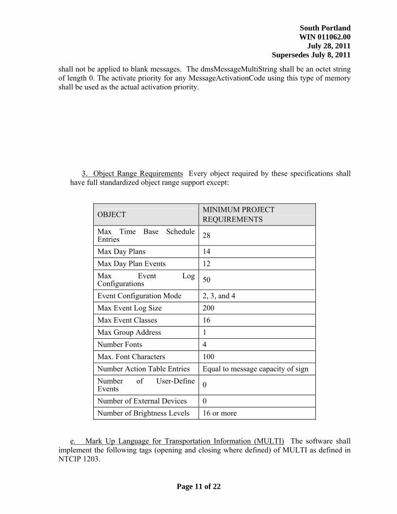
3. Object Range Requirements Every object required by these specifications shall have full standardized object range support except:
OBJECT MINIMUM PROJECT REQUIREMENTS
Max Time Base Schedule Entries 28
Max Day Plans 14 Max Day Plan Events 12 Max Event Log Configurations 50
Event Configuration Mode 2, 3, and 4 Max Event Log Size 200 Max Event Classes 16 Max Group Address 1 Number Fonts 4 Max. Font Characters 100 Number Action Table Entries Equal to message capacity of sign Number of User-Define Events 0
Number of External Devices 0 Number of Brightness Levels 16 or more
e. Mark Up Language for Transportation Information (MULTI) The software shall implement the following tags (opening and closing where defined) of MULTI as defined in NTCIP 1203.
Page 11 of 22
South Portland WIN 011062.00
July 28, 2011 Supersedes July 8, 2011
• Fields for 12 hour time, day of month, month, four digit year, and current speed in mph.
• Flash
• Font
• Justification Line
• Justification Page
• Moving Text
• New Line
• New Page
• Page Time
• Hexadecimal Character
f. Other NTCIP Standards All communication shall conform to NTCIP 2202, Internet (TCP/IP and UDP/IP) Transport Protocol; NTCIP 1102, Octet Encoding Rules (OER) Base Profile; and NTCIP 1103, Transportation Management Protocols. Communication with the signs shall use SNMP only.
Trailer a. Hitch The trailer shall have a fixed height, pintal hitch.
b. Dimensions The trailer shall be no more than 20 feet (6 m) long with the tongue in place, and no more than eight feet (2.5 m) wide. c. Tongue The tongue shall be removable. No tools shall be required for removal or remounting of the tongue. It shall not be necessary to disconnect any hydraulic brake lines to effect complete removal, and it shall not be necessary to bleed the brake system upon re-installation of the tongue. d. Safety Chains Both the tongue and coupler shall have safety chains attached. e. Compartments The trailer shall have lockable, weatherproof compartments for the controller and batteries. The battery compartment shall be centrally positioned to promote stability of the trailer
f. Leveling Jacks The trailer chassis shall have at each corner a leveling jack affixed in such a manner that the jacks may be readily placed and locked in a horizontal position for traveling without the use of any tools. g. Conspicuity Material All faces of the trailer shall be delineated on a permanent basis by affixing retro-reflective material, known as conspicuity material, in a continuous line as seen by oncoming drivers.”
Page 12 of 22

South Portland WIN 011062.00
July 28, 2011 Supersedes July 8, 2011
Miscellaneous Requirements
a. Radar-Ready The sign shall have an on-board Doppler radar speed detector installed, such that the speed of approaching vehicles can be displayed on the sign. All necessary software and firmware shall be included with this order. b. Grounding All electrical systems, surge protectors, antenna grounds, and the trailer shall connect to a common ground that also connects to a grounding lug on the outside of the trailer. Label the lug “EARTH GROUND”.
Control Software The software is to enable traffic management staff to control and monitor the signs. It is also to enable a maintenance technician at a sign to exercise all sign features, examine event logs, and run diagnostic tests. It is expected that the software will be the DMS manufacturer’s standard product, with minimal customization. The software for use by maintenance technicians need not be identical to that used by the traffic management staff, although it must have equivalent capabilities. The manufacturer is to install the software on three of the Department’s existing computers and provide the Department with the right and means to install the same software on at least ten other computers. It is expected that this software will be used to control additional portable and permanent changeable message signs that the Department will buy. Currently the department uses a product called Vanguard. The manufacture will supply all necessary font and configuration files to integrate the signs into the Vanguard product. Installation and testing shall occur at the same time as the manufacturers software is installed as above. Computer Compatibility Three of the computers will be stationary desktop computers with Intel Pentium IV (1.8 GHz) processors and the other three will be notebook computers with Intel Pentium M (1.5 GHz) processors. All will have Windows XP operating systems (with Service Pack 3), 512 MB or more of memory, a 20 GB hard drive and internet connectivity. The software shall work with these computers. The manufacturer shall visit two Department facilities to install this software. The main control computer, a desktop, will be in the radio room at the Department’s Augusta Headquarters. Augusta: Maine Department of Transportation Child Street Augusta, Maine 04333
Page 13 of 22
South Portland WIN 011062.00
July 28, 2011 Supersedes July 8, 2011
Password Protection Only users, who have proper authorization, as indicated by their passwords, shall be able to undertake the following actions:
• Place equipment on standby.
• Change sign messages, blank signs, and change message priority.
• Replace or delete messages stored in a DMS controller's memory.
• Display test patterns on a sign.
• Change or delete the sign computer's schedule.
• Modify the message library on the sign computer's hard disk.
• Change sign configuration parameters.
• Delete the event log.
• View passwords.
• Change passwords and privileges.
Each user shall have a different password. Users may be granted or denied permission to use each protected command independently. Via an encrypted lookup table, the computer shall determine which of the protected commands a user may use. The software shall ask the user for his password at the time the protected command is entered. The computer shall not carry out these commands unless the user has the proper privileges. Off Line Status A user shall be able to take a sign off line, causing it to be ignored by the sign computer. This will be used when a malfunctioning sign is generating an excessive number of alarms. When a user attempts to control an off line sign, a message shall appear on his screen informing him that the sign is out of service. When a user takes a sign off line, the software shall ask the user to type in a comment of up to 100 characters explaining the action. The comment field may be left blank. The computer shall also record the user's name, based on his password, and include the name and comment in the failure report described below. Message Library The sign computer shall store a library of at least 999 messages on its hard disk. In addition to the message text, the file shall contain all the MULTI control codes needed for a sign to properly display the message When adding a message to the library, a user shall specify the message name. If a message with the same name already exists in the library, the software shall notify the user and give him the options of replacing the existing file or selecting a new name for the message he has just created. A user shall also be able to delete library messages from within the program. The program shall ask the user to confirm each message deletion before actually deleting the file.
Page 14 of 22
South Portland WIN 011062.00
July 28, 2011 Supersedes July 8, 2011
If the user is seeking a message to display, the software shall present a list so that the user can choose one. When the user makes his selection, the software shall display the entire message, exactly as it would appear on a sign, and shall ask the user to confirm that this is the message desired. The user shall then be able to post the message on one or more signs, edit the message, or do nothing with it. Sign Control Future signs may have different line lengths and heights (measured in pixels) than the signs provided in this project, and may have more or fewer lines. The software shall display messages as a matrix of dots that replicate the way the message will actually appear on a selected sign. The presentation should be based on the assigned font and the height and width (in pixels) of the display, as stored in a data base maintained by the sign computer. This type of display will be used during message creation and editing, as well as when displaying to a user the message currently on a sign. If the user is displaying a message from the library or creating a message without specifying what sign it will go on, the display shall be based on the characteristics of the signs provided in this project. Upon creating or revising a message, the user shall be able to save it in the message library on the sign computer's hard disk or send it directly to one or more DMS controllers for storage or display. When a user sends a message to one or more signs, the sign computer shall automatically check to be sure that the message will fit on the sign. This checking shall take into account the selected fonts and the size of the sign's display. If the message won't fit, the computer shall alert the user and not post the message. If a user chooses to send the same message to multiple signs, the software shall present the user with a list of all signs, so that the user can check off which signs the new message goes to. The screen shall also give the user a choice of “All Signs”. The list shall identify signs by roadway and milepost. Using a single command, the user shall be able to cause the message to be stored in all the signs he specified, replacing those previously stored in the controllers. Similarly, the user shall be able to use a single command to have all the selected signs display the same message, or the same message number. In addition to entering commands for immediate execution, a user may store commands in the sign computer for future execution. For example, the user may want to conduct a pixel test of every sign each night at 3:00 AM. A user shall be able to quickly and easily create, modify, suspend, or cancel a schedule of commands for the sign computer to issue to specified DMS controllers. The user shall be able to specify the same action at the same time for multiple signs, in the same way as was described in the preceding paragraph. A user shall also be able to schedule the printing of sign-related reports. A user shall not be able to schedule any command that he does not have the privilege to execute directly. The schedule shall show the name of the user who scheduled each command, based on his password. Actions that would be recorded in the event log if a user commanded them directly shall also be logged when they result from a
Page 15 of 22

South Portland WIN 011062.00
July 28, 2011 Supersedes July 8, 2011
scheduled command. The record shall include the user's name and an indication that the command was scheduled. The software shall provide a single command that not only transmits a message to a sign (after confirming that it fits) but also causes the sign to immediately display that message on the sign (after confirming that the transmission was error free). Status Monitoring The sign computer shall maintain an event log file on its hard disk with a record for each appearance or disappearance of an alarm from a sign. The file shall be in ASCII format with fixed-length fields separated by spaces, suitable for transfer to spreadsheet and data base management software. The record shall include the date, time, sign ID, and nature of the change. If the alarm indicates a change in the sign display, the log shall include the exact text of the message, the device from which it was commanded, and, if commanded via the sign computer, the name of the person posting the message, based on his password. The log file shall include this same information each time a message is downloaded to a sign's memory from the sign computer. The log shall also record each time a user at the sign computer does the following: • Changes the priority of a message. • Changes the schedule. • Changes a message in the library on the computer's hard disk. The record shall include the user's name based on his password. The log shall also record the beginning and end of communication failures. The sign computer shall deem a communication failure to have occurred if it does not get an error-free response to two consecutive commands to a controller. The computer shall deem a controller recovered if it responds properly to a command. Reports The system shall provide the following reports to the user's screen, a disk file named by the user, or to the printer, as specified by the user:
• Equipment Failures. Lists each sign that is currently malfunctioning, along with the time and date of failure and a phrase indicating the nature of the problem. Also lists each DMS controller that is off line, along with the date and time it was taken off line, the comment written by the user who took it off line, and the user's name based on his password.
Page 16 of 22
South Portland WIN 011062.00
July 28, 2011 Supersedes July 8, 2011
• Sign System Configuration. Lists the current values of all configuration parameters
stored in the sign computer, clearly labeled. It includes such things as communication address. It does not include operating parameters stored in the DMS controllers.
• Individual Sign Configuration. Lists the current values of all changeable parameters
stored in a DMS controller, clearly labeled. It includes such things as temperature thresholds. This report shall cover all signs, or a particular sign, as specified by the user. The information displayed shall be uploaded from the DMS controllers at the time the report is requested. If the sign computer is unable to upload the data from a particular sign, it shall use the corresponding data on its hard disk, but shall indicate in the report that the data is from the hard disk and may not be current.
• Current Sign Status. Lists sign location, text of message currently displayed, the priority
value of the message, storage location of the message in the sign's memory, entity that caused the message to be displayed, and controller status (failed, working, or off line) for each sign in the system. This report shall cover all signs, or a particular sign, as specified by the user.
• Event Log. Lists all information in the control computer’s event log file, with each field
clearly labeled. The user shall be able to specify that only events between certain times, or pertaining to a certain sign, or pertaining to a certain type of event, or any combination of the foregoing, shall be included in the report. Events shall be listed chronologically.
• Message Library. Lists the text of each frame of each message in the message library,
along with the duration for which the frame is displayed. Also lists the message's file name and latest revision date. Each frame shall be displayed in the report in the same way it would appear on a sign, with regard to text centering, bolding, and justification. Flashing text shall be underlined. Messages shall be grouped by subdirectory, and a user shall be able to specify that only certain subdirectories be included.
• Sign Computer’s Schedule. Lists all information in the sign computer's schedule, clearly
labeled. The user shall be able to specify that only events between certain times, or pertaining to a certain sign, or pertaining to a certain type of event, or any combination of the foregoing, shall be included in the report. Events shall be listed chronologically.
• Sign Memory. Lists sign ID and location and the text of each message stored in the sign.
The message portion of the report shall indicate the message's memory location number and shall display the text of each frame of the message, along with the duration for which the frame is displayed. Each frame shall be displayed in the report in the same way it would appear on a sign, with regard to text centering, bolding, and justification. Flashing text shall be underlined. All information shall be clearly labeled. The user shall be able to specify that the report cover only a particular sign, or all signs. The information displayed shall be uploaded from the DMS controllers at the time the report is requested.
Page 17 of 22

South Portland WIN 011062.00
July 28, 2011 Supersedes July 8, 2011
If the sign computer is unable to upload the data from a particular sign, it shall use the corresponding data on its hard disk, but shall indicate in the report that the data is from the hard disk and may not be current.
• Bad Pixel Maps. Consist of a matrix display indicating which display elements of a sign
have failed, according to the DMS controller. The user shall be able to specify that the report cover only a particular sign or all signs with display problems. If the user specifies all signs with display problems, the report will cover all signs whose controllers are currently reporting malfunctioning drivers or display elements.
The time and date for which the information is current shall appear on every page of each printed report. All pages shall be numbered. Alarms The sign computer shall issue alarms by beeping and displaying a message clearly identifying the problem in a prominent box that pops up on the user's screen. The box shall disappear when the user clicks on it and the beeping shall stop. If the alarm is of the type called "recurring", the beeping and screen message recur every 15 minutes as long as the condition persists. The sign computer shall issue a single alarm for the following situations:
• A new sign failure. • The sign computer is unable to change a sign's display as scheduled because the currently displayed message has a higher priority.
A sign computer shall issue a recurring alarm if its hard disk is over 90 percent full. User Interface The user shall enter commands by selecting from menus. The user shall make selections from menus and from lists of signs, messages, and options using a mouse. The interface shall be easy to use, minimizing memorization and opportunities for errors. The interface shall automatically check commands for out-of-range values and other errors. When it checks an error, it shall beep, reject the command or data, and provide the user with a clear explanation. The software shall have the complete text of the software operator's manual stored on disk, readily available to the user. Communication Interface The software shall be capable of contacting signs by dial-up telephone and over an Ethernet network. It shall use the appropriate communication method for each sign, based on information stored in the computer’s database. If a sign is connected to both telephone and Ethernet networks, the software shall use the dial-up link as a backup when the Ethernet network is not successful. Spare Parts Provide the following spare parts:
Page 18 of 22

South Portland WIN 011062.00
July 28, 2011 Supersedes July 8, 2011
• Display modules: 20 percent of the total provided. • Controllers: two. • Display power supplies: ten percent of total provided(At least one). • Other circuit boards used in the sign, if not covered by the previous items: one of each
type. • Surge protectors: two of each type. • Battery charging unit: one. • Battery: sufficient to equal the system operating voltage (2x 6 volt for 12 volt system)
Testing. The manufacturer shall test the signs, software, and spare parts. The manufacturer shall develop the test procedures and revise them as necessary to meet the Engineer’s approval. Prior to the testing, the manufacturer shall deliver all signs and spare parts to the Department’s Fairfield facility, shall successfully install the software on the Department’s computers, shall conduct all the tests in the test plans, and shall correct any deficiencies found.
When the manufacturer is confident that the signs, software, and parts will pass the test, he shall arrange for the Department’s representative’s to witness the testing. He shall contact the Engineer at least two weeks in advance of the proposed testing date and shall arrange for testing to begin at a mutually convenient time. All testing will be done on the same day (or two days, if necessary) at the Department’s Fairfield facility. The installation contractor may witness this testing if he or she chooses. The manufacturer shall provide all materials and equipment needed for testing and shall prepare a written report of the test results.
Sign Testing The test procedure shall be designed to uncover manufacturing defects and shipping damage of all types. The test shall include a visual inspection of the sign. Among the aspects that must be tested are the following:
• All diagnostic routines provided by the manufacturer. • Proper operation of every pixel, including uniform brightness at all brightness levels and
proper current consumption. • Proper wiring of the display modules, checked by displaying a text message that
identifies the modules’ proper row and column positions. • Appropriate display brightness for day and night conditions, and brightness when the sun
at its worst condition for the location. • Proper aiming of the display modules. • Proper entry of messages into memory. • Proper operation of sign monitoring. • Proper operation of sensors for alarm conditions. • Correct wiring of sensors and alarms to the controller's inputs. • Proper remote access and control using the central and laptop software provided in this
project.
Page 19 of 22
South Portland WIN 011062.00
July 28, 2011 Supersedes July 8, 2011
Software Testing The purpose of the sign computer software test is to demonstrate that the
software operates reliably and is in full compliance with the specifications. The manufacturer shall conduct the tests following the approved test plan but, if practical, shall also perform any supplemental tests requested by the Department's representatives at the time of testing. To be accepted, the software must pass all the tests. The test plan shall test every interface, feature, and function of the software, including features present but not required by these specifications. The testing shall demonstrate that the software deals appropriately with communication errors and operator errors. The testing shall confirm that the signs can be monitored and controlled from each of the Department’s computers on which software was installed. Spare Parts Testing Test the parts by substituting them into a working sign. Training General Within two weeks of successful completion of testing, the manufacturer shall train the Department’s operations and maintenance staff at the Fairfield facility. All the signs will still be at that facility for use during training.
In the training, each trainee shall receive copies of the appropriate manuals. The training shall be conducted in such a way as to familiarize the trainees with the manuals (and any other handouts provided) so that the trainees are able to make efficient use of those materials after the training. All course material, in reproducible form, shall be delivered to the Engineer immediately following course completion.
The manufacturer shall provide all tools and instruments needed for the training.
Installation Training The class will consist of up to 15 people, some from the Department and others from the contractor who is to install the signs. It shall cover proper towing and positioning of the sign, leveling, removing the tongue, raising and lowering the message board, aiming the message board, aiming the solar panels, connections to communication and power, and all other setup activities. It shall last four hours. Maintenance Training The maintenance training shall be provided for 12 hours for at least ten maintenance technicians with electronics backgrounds. These trainees will also attend the training session for sign operators, so material in that class need not be repeated in the maintenance training. The training shall include theory of operation, circuit description, field adjustments, preventive maintenance procedures, troubleshooting, operation of diagnostic and configuration software, use of the event log, and repair of components.
Page 20 of 22

South Portland WIN 011062.00
July 28, 2011 Supersedes July 8, 2011
In addition to classroom training, it shall include “hands on” training using the signs provided in this project. That training shall include use of the control panels (if provided), control of the signs using the Department’s notebook computers, display module replacement, controller replacement, battery replacement, and troubleshooting. Spare parts furnished under this contract may be used for the replacement activities. Each trainee shall use the Department’s laptop software to run all the diagnostic messages, create a message, schedule the message, and adjust the sign’s brightness. Each shall use the sign controller’s front panel to run stored messages and determine the sign’s current status.
Operator Training The training shall be provided for a minimum of four hours for at least ten engineering and operations personnel. The training shall include a complete demonstration of the operation and capabilities of the signs and software, as well as opportunities for the trainees to create and store messages, post messages, and schedule messages.
Technical Support Phone numbers provided for technical support must be attended by a person who can answer questions or promptly find the answer to questions. An answering machine or answering service does not constitute technical support. The telephone support required by these specifications shall be provided at least eight hours a day on all work days.
On-Site Support The manufacturer shall have a representative present when the installation
contractor installs the first sign. The representative shall observe the installation, provide additional training to the contractor as required, and ensure that the sign is installed correctly. If the manufacturer’s representative is not confident that the contractor can install the remaining signs without assistance, the representative shall immediately notify the Engineer.
Telephone Support During Installation The manufacturer shall provide telephone support to
the installation contractor during installation. This support shall be available until all the signs have been installed.
Telephone Support for Operation and Maintenance The manufacturer shall provide
telephone support to the Department’s operations and maintenance staff for a period of one year following the acceptance of the signs. This will be at no charge to the Department. Method of Measurement Portable Changeable Message Signs will be measured by Each. Basis of Payment The accepted portable changeable message signs will be paid for at the contract unit price each. Such price will be full compensation for furnishing and testing the signs, as well as all sign-related documentation. Control software, spare parts, training and technical support as described within this Special Provision will be included in the contract unit price for the Portable Changeable Message Signs.
Payment will be made under:
Page 21 of 22

South Portland WIN 011062.00
July 28, 2011 Supersedes July 8, 2011
Pay Item Pay Unit
652.43 Portable Changeable Message Sign – Retained By Department EA
Page 22 of 22