source selection for the ilc - stanford university
TRANSCRIPT

RF source selection for the ILCRF source selection for the ILC
Ed Wright, Heinz Bohlen, Steve Lenci & Adam Balkcum
Communications and Power Industries, Inc.Microwave Power Products Division
611 Hansen WayPalo Alto, CA, 94303

RF source selection for the ILCRF source selection for the ILCBackground
High-volume manufacturing: accommodating peak demandVKS-7964M for XM-RadioVKP-8291A for SNS
Available sources for the ILCVKL-8301 TESLA MBK
Second-generation sources for the ILCMBKHOM IOT
VHP-8330AILC HOM IOT
Conclusion

High Volume ManufacturingHigh Volume ManufacturingVKS-7964M developed for Satellite Digital Audio Radio
Both Exhaust and Test were identified as production bottlenecks
Parameter Value UnitsPower Output 3.0* / 10.0** kWBeam Voltage 13.8 kVBeam Current 1.95 ASupply Power 14.0 kWEfficiency 21* / 46** %Collectors 4Frequency 2338 MHz1dB Bandwidth 8 MHzSaturated Gain 45 dBCooling Method AirCoolant Flow Rate 1500 / 680 lb/hr / kg/hrPressure Drop 3.5 / 0.87 in/H2O / kPaTotal Weight 275 / 125 lbs / kg
* Customer operating point ** Saturation
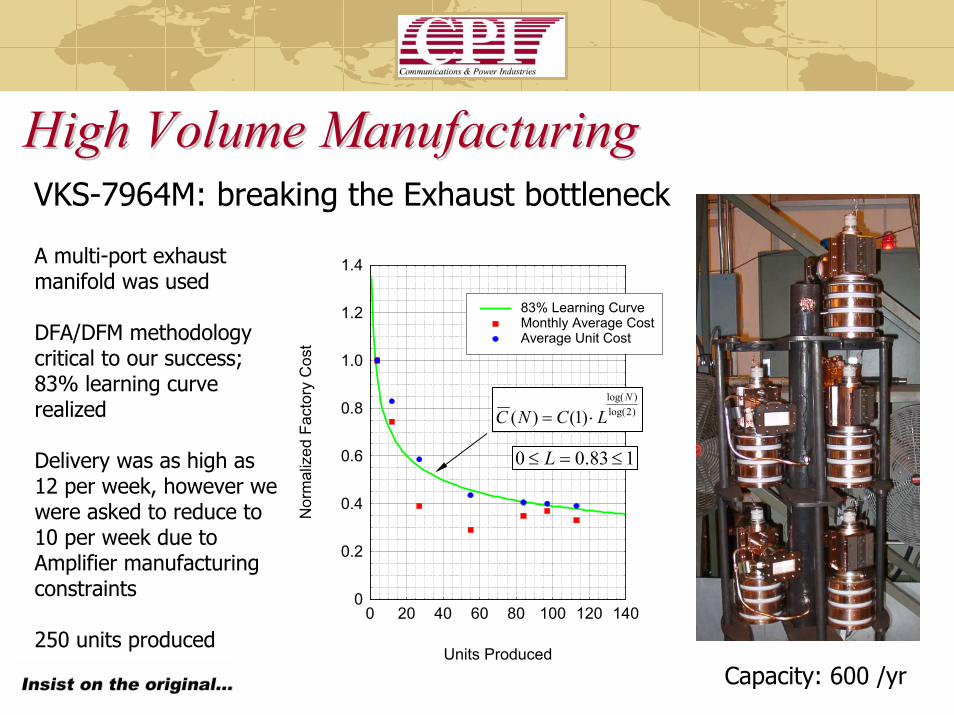
High Volume ManufacturingHigh Volume ManufacturingVKS-7964M: breaking the Exhaust bottleneck
A multi-port exhaust manifold was used
DFA/DFM methodology critical to our success; 83% learning curve realized
Delivery was as high as 12 per week, however we were asked to reduce to 10 per week due to Amplifier manufacturing constraints
250 units produced
0
0.2
0.4
0.6
0.8
1.0
1.2
1.4
0 20 40 60 80 100 120 140
83% Learning CurveMonthly Average CostAverage Unit Cost
Units Produced
Nor
mal
ized
Fac
tory
Cos
t
)2log()log(
)1()(N
LCNC ⋅=
183.00 ≤=≤ L
Capacity: 600 /yr

VKS-7964M: breaking the Test bottleneckTubes conditioned and tested in deliverable amplifiersOne amplifier was retained at the end of the program for test
This model would make sense for ILC
High Volume ManufacturingHigh Volume Manufacturing
CPI/SatcomFinal test, Burn-in
First test: Green tubes received from CPI/MPP
Amplifier AssemblyCapacity: 500 /yr
Photo and Layout courtesy of CPI-Satcom

High Volume ManufacturingHigh Volume ManufacturingVKP-8291A developed for SNS*Exhaust identified as the only Production bottleneck
Parameter Value UnitsPeak Power 550 kW (min)Average Power 50 kW (min)Beam Voltage 76.5 kV (max)Beam Current 11.5 A (max)Efficiency 65 %, minFrequency 805 MHzRF Duty Cycle 9 %RF Pulse Length 1.5 msGain 50 dB (min)
*Work supported by LANL and ORNL

High Volume ManufacturingHigh Volume ManufacturingVKP-8291A:breaking the Exhaust bottleneck
Exhaust capacity was found to limit our goal of producing 1 unit per week. A dual-port exhaust system overcame the bottleneck
77
81
65
0
10
20
30
40
50
60
70
80
90
Apr-02
Jun-0
2Aug
-02Oct-
02Dec
-02Feb
-03Apr-
03Ju
n-03
Aug-03
Oct-03
Dec-03
Feb-04
Apr-04
Jun-0
4Aug
-04Oct-
04Dec
-04Feb
-05Apr-
05
Uni
ts
Cumulative Actual
Delivery Per Contract Mod 3 (81 Total)
Original Contract (65 units)
14 mos.
Capacity: 52/yr

VKLVKL--8301 TESLA MBK*8301 TESLA MBK*Background
MBK developed for the TESLA V/UV-FEL, X-FEL
Candidate ILC Source
TESLA approach: one MBK will feed 36
Superconducting cavity cells (3 cryomodules
with 12 cavities per)
HOM Technology; TM020 cavities
Factory CSI complete
Delivered to DESY
*Work supported by DESY

Design Highlights
Confined-flow focusing
State-of-the-art focusing system developed for
off-axis electron beams*
High order Mode (HOM) Technology: TM020 Cavity
Proven high-power capabilities
No RF breakdown observed
Stable; No oscillations observed
VKLVKL--8301 TESLA MBK8301 TESLA MBK
*Domestic patent granted, Foreign patent pending
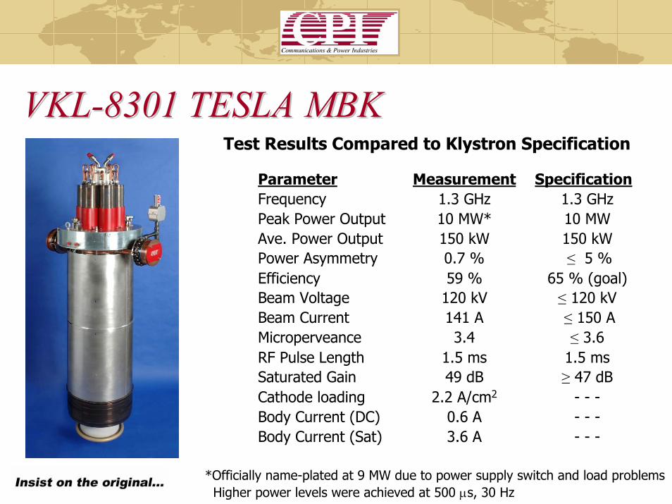
Parameter Measurement SpecificationFrequency 1.3 GHz 1.3 GHz Peak Power Output 10 MW* 10 MWAve. Power Output 150 kW 150 kWPower Asymmetry 0.7 % ≤ 5 %Efficiency 59 % 65 % (goal)Beam Voltage 120 kV ≤ 120 kVBeam Current 141 A ≤ 150 AMicroperveance 3.4 ≤ 3.6RF Pulse Length 1.5 ms 1.5 msSaturated Gain 49 dB ≥ 47 dBCathode loading 2.2 A/cm2 - - -Body Current (DC) 0.6 A - - -Body Current (Sat) 3.6 A - - -
VKLVKL--8301 TESLA MBK8301 TESLA MBKTest Results Compared to Klystron Specification
*Officially name-plated at 9 MW due to power supply switch and load problemsHigher power levels were achieved at 500 µs, 30 Hz

Output Power vs. Frequency
0
2
4
6
8
10
12
1296 1298 1300 1302 1304 1306Frequency (MHz)
Out
put P
ower
(MW
)
Minimum -1 dB Bandwidth
Pd,sat = 160 W
-1 dB-2 dB
-3 dB
Eb = 120 kVIb = 141 A
VKLVKL--8301 TESLA MBK8301 TESLA MBK
500 µs, 30 Hz
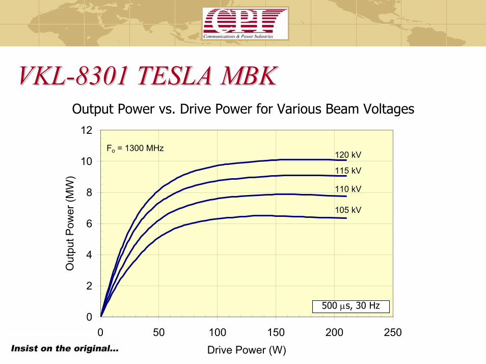
VKLVKL--8301 TESLA MBK8301 TESLA MBKOutput Power vs. Drive Power for Various Beam Voltages
0
2
4
6
8
10
12
0 50 100 150 200 250Drive Power (W)
Out
put P
ower
(MW
)
120 kV
115 kV
110 kV
105 kV
Fo = 1300 MHz
500 µs, 30 Hz

Output Power vs. Drive Power Variation into a 1.2:1 VSWR Mismatch
0
2
4
6
8
10
12
0 50 100 150 200 250Drive Power (W)
Out
put P
ower
(MW
) 01
23 4
5
Fo = 1300 MHzEb = 120 kVIb = 141 A
One trip around the Smith Chart…
VKLVKL--8301 TESLA MBK8301 TESLA MBK
500 µs, 30 Hz

VKLVKL--8301 TESLA MBK8301 TESLA MBKThe VKL-8301 MBK successfully demonstrated confined-flow technology for multiple off-axis electron beams
The next steps are:Realize the 65% efficiency level
Analysis is underway nowImplement this change on the next MBK
Design and fabricate TESLA X-FEL horizontal version
A contract for more…

Second Generation Sources Second Generation Sources -- MBKMBKWe are delighted with the performance of the VKL-8301 prototype. It should serve DESY well. Here are some interesting observations
The VKL-8301 voltage and current were established by existing fundamental mode MBKs
The use of TM020 cavities approach makes this the largest diameter MBK proposed for TESLA
Large cathode bolt-circle of the CPI MBK ‘underutilized’; more electron beams can be incorporated into this design
What would a second generation MBK Look like?

Second Generation Sources Second Generation Sources -- MBKMBKElectrically… a 10 MW peak , 150 kW average power device would:
Number of Beams 6 12 18 unitsBeam Microperveance 0.58 0.8 0.8 µA/V1.5
Total Microperveance 3.492 9.6 14.4 µA/V1.5
Voltage 114 76 65 kVCurrent 134.7 201.9 237.5 A
Current per Beam 22.5 16.8 13.2 ABeam-Beam separation 5.50 2.75 1.83 inches
Tunnel Diameter (γa=0.5 rad) 1.019 0.818 0.750 inchesBeam Diameter (60% fill) 0.611 0.491 0.450 inches
Brillouin Field 269 323 326 GaussBeam Current Density Jo 11.9 13.8 12.8 A/cm2
Plasma Reduction Factor 0.185 0.183 0.183 (---)Reduced Plasma Prop. Factor 4.255 6.303 6.926 deg/inCircuit Length (I/P to O/P gap) 45.8 30.9 28.1 inches
HM MBK
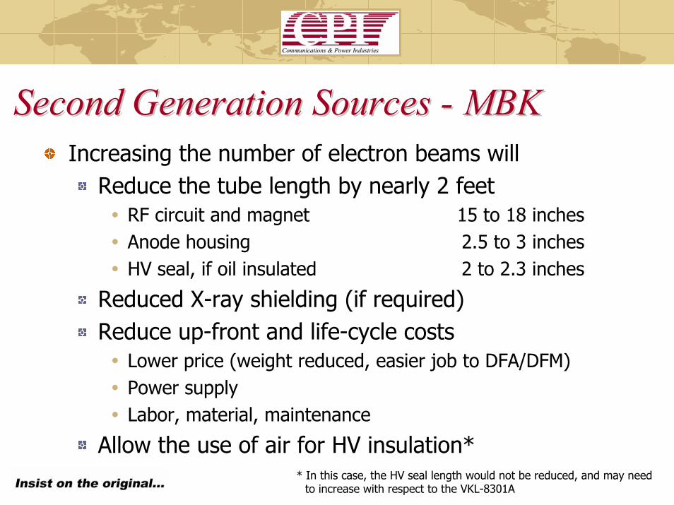
Second Generation Sources Second Generation Sources -- MBKMBKIncreasing the number of electron beams will
Reduce the tube length by nearly 2 feetRF circuit and magnet 15 to 18 inchesAnode housing 2.5 to 3 inchesHV seal, if oil insulated 2 to 2.3 inches
Reduced X-ray shielding (if required)Reduce up-front and life-cycle costs
Lower price (weight reduced, easier job to DFA/DFM)Power supplyLabor, material, maintenance
Allow the use of air for HV insulation** In this case, the HV seal length would not be reduced, and may need
to increase with respect to the VKL-8301A

Second Generation Sources Second Generation Sources –– MBKMBKWe’ve shown that the advanced technology developed for the VKL-8301 can enhance the capabilities of a next generation MBK for ILC
TM020 cavity technologyConfined-Flow Focusing of off-axis electron beams
These developments open the door for a technology with superior performance characteristics
What makes it superior?
IOT TechnologyIOT Technology

IOT’s are the device of choice for commercial UHF broadcast, occupying sockets once held by klystrons. Here’s why
Pout
Pin Pin
Pout
IOT(Klystrode)
+6 dB
ηsat ~ 65-68%
η ~ 52-55%
Back-off for feedback
High gain Low Gain
Long-pulse excursions possible
Short-pulse excursions possible
Unstable region
...42 +++≈ iiio cVbVaVV3rd, 5th, ... IM products suppressed3rd, 5th, ... IM products in-band
...53 +++≈ iiio cVbVaVV
IOT’s don’t saturate! Built-in headroom for feedback
η~ 70%
Klystron/MBK
Operating Power Level
Second Generation Sources Second Generation Sources –– HOM IOTHOM IOTAs mentioned before, the advances made developing the VKL-8301 have direct bearing on the development of an HOM IOT for ILC
TM020 cavity technologyConfined-Flow Focusing of off-axis electron beams
The HOM IOT considered ‘enabling technology’ for several systems planned by the DoD
Scientific applications abound
Next, some background…

IOT Developments IOT Developments –– VHPVHP--8330A HOM IOT8330A HOM IOTVHP-8330A – Annular beam prototype
Developed for APT*
Gun
RF Input
CollectorSolenoid,
O/P Cavity
Typical Operating ParametersPower Output 1000 kW (min)Beam Voltage 45 kV (max)Beam Current 31 A (max)Frequency 700 MHz1dB Bandwidth ± 0.7 MHz (min)Gain 23 dB (min)Efficiency 71 % (min)Diameter 30/76 in/cmHeight 51/130 in/cmWeight 1000/450 lbs/kgCollector Coolant Flow 220 gpmBody Coolant Flow 10 gpmO/P Window Cooling (Air) 35 cfm
*Work supported by LANL
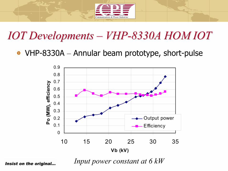
IOT Developments IOT Developments –– VHPVHP--8330A HOM IOT8330A HOM IOTVHP-8330A – Annular beam prototype, short-pulse
0
0.10.2
0.3
0.40.5
0.6
0.70.8
0.9
10 15 20 25 30 35Vb (kV)
Po (M
W),
effic
ienc
y
Output power Efficiency
Input power constant at 6 kW

IOT Developments IOT Developments –– VHPVHP--8330A HOM IOT8330A HOM IOTVHP-8330A – Annular beam prototype, short-pulse
00.10.20.30.40.50.60.70.80.9
1
30 35 40 45 50Ib (A)
Po (M
W),
effic
ienc
y
Output powerEfficiency
Beam voltage constant at 31 kV
Note: Efficiency remains flat over a broad range of
output power levels
IOT Developments IOT Developments –– VHPVHP--8330A HOM IOT8330A HOM IOTVHP-8330A – Annular beam prototype
ProblemThe first HOM-IOT project confirmed simulation results to a high degreeThe annular cathode / grid configuration was mechanically vulnerable during bake-out, leading to grid-cathode short circuits and reduced efficiency during test
SolutionReplace the annular configuration with a circular arrangement of standard IOT guns. Focusing the electron beams in such a system has become viable through the CPI MBK development for the TESLA V/UV and X-FEL
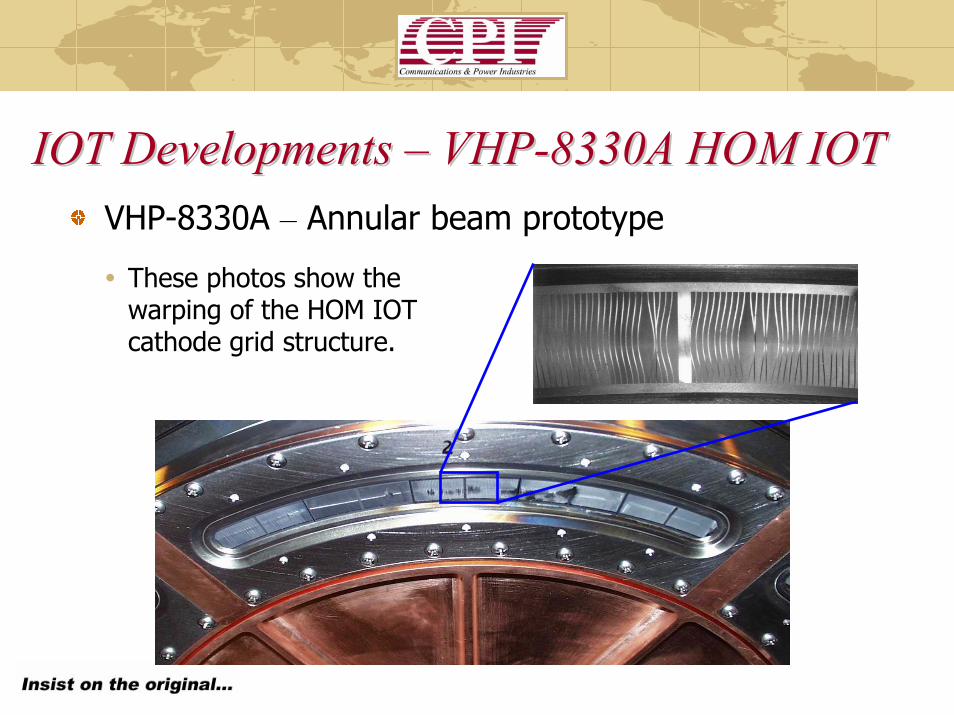
IOT Developments IOT Developments –– VHPVHP--8330A HOM IOT8330A HOM IOTVHP-8330A – Annular beam prototype
These photos show the warping of the HOM IOT cathode grid structure.

IOT Developments IOT Developments –– VHPVHP--8330A HOM IOT8330A HOM IOTVHP-8330A and VHP-8330B
5x Annular Beams Nx Round Beams

IOT Developments IOT Developments –– VHPVHP--8330B HOM IOT8330B HOM IOTVHP-8330B – Round beam prototype 3-1/8 Coaxial Input
Gun Housing
Hybrid TM020 Output Cavity
Collector
Water Inlet / Outlet
WR-1500 Waveguide Output
Typical Operating ParametersPower Output 1000 kW (min)Beam Voltage 42 kV (nom)Beam Current 33 A (nom)Frequency 650-750 MHz1dB Bandwidth 6 MHz (min)Gain 25 dB (min)Efficiency 71.5 % (min)Cathode Loading 0.4 A/cm2
ElectromagnetMain Coil Current 18 AMain Coil Voltage 49 V
SizeDiameter 30/76 in / cmHeight 51/130 in / cmWeight 1000 / 450 lbs / kg

IOT Developments IOT Developments –– VHPVHP--8330B HOM IOT8330B HOM IOTMany opportunities exist…
ScientificMilitaryHomeland Security
HOM IOT will be commonplace in the next ten years
They will displace klystrons as the device-of-choice for high power UHF and L-band projects, as we’ve seen in the UHF-TV broadcast market
What can be done today for ILC?

Second Generation Sources Second Generation Sources –– HOM IOTHOM IOT
Peak Output Power 5 MW (min)Average Output Power 75 kW (min)Beam Voltage 115 kV (nom)Beam Current 62 A (nom)Current per Beam 5.17 A (nom)Number of Beams 12 ---Frequency 1300 MHz1dB Bandwidth 4 MHz (min)Gain 22 dB (min)Efficiency 70 % (nom)Solenoid Power 1 kWCathode Loading 1.0< A/cm2
Performance of a 5 MW HOM IOT for ILC
How would the ILC benefit from this technology?How would the ILC benefit from this technology?
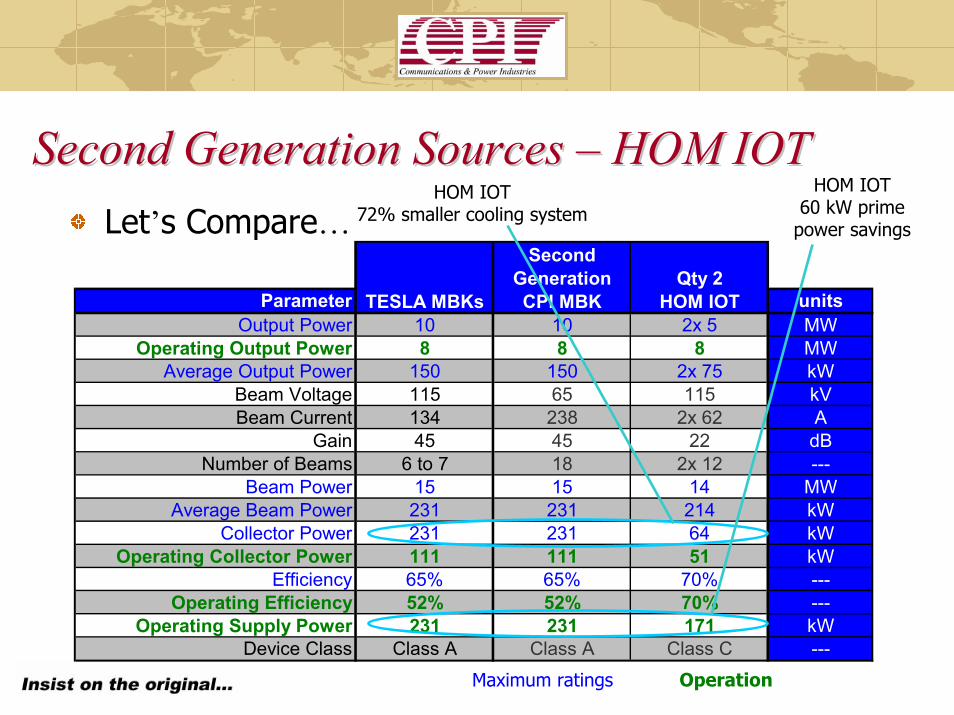
Second Generation Sources Second Generation Sources –– HOM IOTHOM IOTLet’s Compare…
Parameter unitsOutput Power 10 10 2x 5 MW
Operating Output Power 8 8 8 MWAverage Output Power 150 150 2x 75 kW
Beam Voltage 115 65 115 kVBeam Current 134 238 2x 62 A
Gain 45 45 22 dBNumber of Beams 6 to 7 18 2x 12 ---
Beam Power 15 15 14 MWAverage Beam Power 231 231 214 kW
Collector Power 231 231 64 kWOperating Collector Power 111 111 51 kW
Efficiency 65% 65% 70% ---Operating Efficiency 52% 52% 70% ---
Operating Supply Power 231 231 171 kWDevice Class Class A Class A Class C ---
TESLA MBKs
Second Generation CPI MBK
Qty 2 HOM IOT
HOM IOT72% smaller cooling system
HOM IOT 60 kW prime
power savings
OperationMaximum ratings
Second Generation Sources Second Generation Sources –– HOM IOTHOM IOTA 5 MW L-band HOM IOT has superior performance characteristics when compared to any linear beam device
Smallest footprint, 1/3 the size of the MBK lowest costLess than 1/3 the cooling infrastructure required60 kW less power required (per 10 MW)At ~11¢ kW-hr, 50% uptime $30,00000 /year/10MW savings
For Qty 600, 10 MW peak, 150 kW average power HOM IOTs (operating at 8 MW, 120 kW)
36 MW less prime-power infrastructure / usageAt ~11¢ kW-hr, 50% uptime $18M /year saved
Development of HOM IOT technology for ILC should be a high priority

Second Generation Sources Second Generation Sources –– HOM IOTHOM IOT
Load
Coax-WG Transition
IOT’s at L-band: this IOT will be used to drive TESLA type SC cavities for CW machines being developed now
A pulsed version would be purchased to drive a pair of 5 MW ILC HOM IOTs
Frequency 1300 MHzOutput Power 30 kW CWBeam Voltage 34 kVBeam Current 1.4 AEfficiency 64%Gain 21 dB

RF source selection for the ILCRF source selection for the ILCConclusion
Several examples of flexible manufacturing to meet peak demand were shown
The VKL-8301 10MW TESLA MBK was described
Second-generation sources for ILC were described10 MW 12 to 18 beam MBK5 MW L-band HOM IOT
The benefits of IOT technology should make this a priority for ILC R&D funding