sorvall cellwasher 2
TRANSCRIPT

PN 04505-32
SORVALLCellwasher 2
®
OPERATINGINSTRUCTIONS


OPERATINGINSTRUCTIONS
SORVALL Cellwasher 2Cell WashingSystem
Kendro Laboratory ProductsAsheville, North CarolinaU.S.A.
®
PN 04505-32Issued January 2005

Table of Contents SORVALL® Centrifuges
This manual is a guide to the use of the
SORVALL® Cellwasher 2 Cell Washing System
Data herein has been verified and is believed adequate for the intended use of the Cellwasher 2.Because failure to follow the recommendations set forth in this manual could produce personalinjury or property damage, always follow the recommendations set forth herein. Kendro does notguarantee results and assumes no obligation for the performance of centrifuges or other productsthat are not used in accordance with the instructions provided. This publication is not a license tooperate under, nor a recommendation to infringe upon, any process patents.
The SORVALL Cellwasher 2 is intended to be used in strict accordance with The AmericanAssociation of Blood Banks' guidelines defined in the most recent edition of the AABB TechnicalManual (published by AABB Press. Bethesda, MD).
Publications prior to the Issue Date of this manual may contain data in apparent conflict with thatprovided herein. Please consider all data in this manual to be the most current.
WARNING, CAUTION, and NOTE within the text of this manual are used to emphasizeimportant and critical instructions.
WARNING informs the operator of a hazard or an unsafe practice that could result inpersonal injury, affect the operator’s health, or contaminate the environment.
CAUTION informs the operator of an unsafe practice that could result in damage ofequipment.
NOTE highlights essential information.
CAUTION and WARNING are accompanied by a hazard symbol ! and appear in the leftsidebar near the information they correspond to.
©1988,1995,1996,1998,1999,2002,2003,2004,2005 by Kendro Laboratory Products
ii
Cellwasher 2 Table of Contents
Important Safety InformationCertain potentially dangerous conditions are inherent to the use of all centrifuges. To ensuresafe operation of this centrifuge, anyone using it should be aware of all safe practices and takeall precautions described below and throughout this manual.
WARNING
When using radioactive, toxic, or pathogenic materials, be aware of all characteristics of thematerials and the hazards associated with them in the event leakage occurs during cell washing. Ifleakage does occur, neither the Cellwasher 2 nor the rotor can protect you from particles dispersedin the air. To protect yourself, we recommend additional precautions be taken to prevent exposureto these materials, e.g., use of controlled ventilation or isolation areas.
Always be aware of the possibility of contamination when using radioactive, toxic, or pathogenicmaterials. Take all necessary precautions and use appropriate decontamination procedures ifexposure occurs.
Never use any material capable of producing flammable or explosive vapors, or creating extremeexothermic reactions.
Use only tubes that meet the criteria provided in this manual (see Tube Selection and Use, Chapter3). Results may be affected if tubes are not within specifications. If tubes are of inadequate strengthso that tube breakage occurs, sample and test results will be lost, the rotor and distributor could bedamaged, and during required cleanup, contact with sharp glass fragments could result in personalinjury.
CAUTION
Do not operate Cellwasher 2 without a rotor properly installed on the drive shaft. See Rotor andDistributor Installation, Chapter 2.
Do not operate the Cellwasher 2 with a rotor out of balance. To do so can cause damage to theCellwasher 2 drive assembly. See Rotor Loading and Balancing, Chapter 2.
We recommend using Coomb's control cells to confirm all negative results.
The Cellwasher 2 can be damaged if connected to the wrong voltage. Check the voltage beforeplugging the instrument into a power source. Kendro is not responsible for incorrect installation.
Always maintain the Cellwasher 2 in the recommended manner. See Chapter 4, Maintenance.
!
Important Safety Information
!
iii

Table of Contents SORVALL® Centrifuges
Page
Safety Information Page . . . . . . . . . . . . . . . . . . . . . . . . . . . . . . . . . iii
Chapter 1. DESCRIPTION
Cellwasher 2 Description . . . . . . . . . . . . . . . . . . . . . . . . . . . . 1-1Applications Information . . . . . . . . . . . . . . . . . . . . . . . . . . . . 1-1Cellwasher 2 Specifications . . . . . . . . . . . . . . . . . . . . . . . . . . 1-2Accessories . . . . . . . . . . . . . . . . . . . . . . . . . . . . . . . . . . . . . . . 1-4
Chapter 2. INSTALLATION
Unpacking . . . . . . . . . . . . . . . . . . . . . . . . . . . . . . . . . . . . . . . . 2-1Location . . . . . . . . . . . . . . . . . . . . . . . . . . . . . . . . . . . . . . . . . . 2-1Environmental Conditions . . . . . . . . . . . . . . . . . . . . . . . . . . . . 2-2Electrical Requirements . . . . . . . . . . . . . . . . . . . . . . . . . . . . . 2-2Tubing Installation . . . . . . . . . . . . . . . . . . . . . . . . . . . . . . . . . . 2-2Rotor and Distributor Installation . . . . . . . . . . . . . . . . . . . . . . 2-5Rotor Loading and Balancing . . . . . . . . . . . . . . . . . . . . . . . . . 2-7
Chapter 3. OPERATION
Controls and Indicators . . . . . . . . . . . . . . . . . . . . . . . . . . . . . . 3-1Principles of Operation . . . . . . . . . . . . . . . . . . . . . . . . . . . . . . 3-3Tube Selection and Use . . . . . . . . . . . . . . . . . . . . . . . . . . . . . . 3-5Priming the System & Adjusting Saline Fill Volume . . . . . . . 3-6Auto Operation . . . . . . . . . . . . . . . . . . . . . . . . . . . . . . . . . . . . 3-8High and Low Speed Operation . . . . . . . . . . . . . . . . . . . . . . . 3-10Tube Breakage . . . . . . . . . . . . . . . . . . . . . . . . . . . . . . . . . . . . . 3-11Momentary Power Interruption . . . . . . . . . . . . . . . . . . . . . . . . 3-12Emergency Sample Recovery . . . . . . . . . . . . . . . . . . . . . . . . . 3-12
Chapter 4. MAINTENANCE
Preventive Maintenance . . . . . . . . . . . . . . . . . . . . . . . . . . . . . . 4-1Sevice Decontamination Policy . . . . . . . . . . . . . . . . . . . . . . . . 4-5Parts Replacement . . . . . . . . . . . . . . . . . . . . . . . . . . . . . . . . . . 4-7Tubing Replacement . . . . . . . . . . . . . . . . . . . . . . . . . . . . . . . . 4-7Fuse Replacement . . . . . . . . . . . . . . . . . . . . . . . . . . . . . . . . . . 4-7Troubleshooting . . . . . . . . . . . . . . . . . . . . . . . . . . . . . . . . . . . . 4-7
iv
Table of Contents

Cellwasher 2 Table of Contents
APPENDIX
WarrantyIndexDecontamination Certificates
List of IllustrationsFigure Page
2-1. Cellwasher 2 Tubing Diagram . . . . . . . . . . . . . . . . . . 2-32-2. Stainless Steel Rotating Bowl Installation . . . . . . . . . 2-62-3. Distributor Installation . . . . . . . . . . . . . . . . . . . . . . . . 2-62-4. Tube Placement for Balancing Less Than 12 Tubes . 2-73-1. Cellwasher 2 Controls and Indicators . . . . . . . . . . . . 3-33-2. Location of Mechanical Override . . . . . . . . . . . . . . . 3-124-1. Collecting Ring Assembly, Exploded View . . . . . . . . 4-34-2. Location of Decant Coil and Drive Ring . . . . . . . . . . 4-104-3. Location of Lift Plate Ring . . . . . . . . . . . . . . . . . . . . 4-10
List of TablesTable Page
1-1. Accessories Supplied . . . . . . . . . . . . . . . . . . . . . . . . . 1-42-1. Parts Location: Tubing Diagram . . . . . . . . . . . . . . . . 2-33-1. Cellwasher 2 Controls and Indicators . . . . . . . . . . . . 3-14-1. Troubleshooting Chart: Problem A . . . . . . . . . . . . . . 4-84-2. Troubleshooting Chart: Problem B . . . . . . . . . . . . . . 4-84-3. Troubleshooting Chart: Problem C . . . . . . . . . . . . . . 4-94-4. Troubleshooting Chart: Problem D . . . . . . . . . . . . . . 4-94-5. Applications Troubleshooting Chart:
False Negative Results . . . . . . . . . . . . . . . . . . . . . . . 4-114-6. Applications Troubleshooting Chart:
False Positive Results . . . . . . . . . . . . . . . . . . . . . . . . 4-124-7. Applications Troubleshooting Chart:
Inconsistent Reaction Strength. . . . . . . . . . . . . . . . . 4-13
v/vi


Cellwasher 2 Description
1-1
Chapter 1: DESCRIPTIONThis manual contains information required to operate and maintain the SORVALL® Cellwasher 2 CellWashing System. If you require additional information regarding operation or maintenance, please contactKendro for assistance. In the United States, call Kendro toll-free 1-800-522-7746; outside the UnitedStates, contact the nearest Kendro office (see back cover) or your local representative for SORVALL®
products. SORVALL® product information is available on our internet web site at http://www.kendro.comor http://www.kendro.de.
* The Cellwasher 2 is not designed to automatically separate donor whole blood to createthe necessary 2 to 5% red blood cell/saline suspension. The Cellwasher 2 may, however,be used as a centrifuge to manually separate red blood cells from whole blood.
Cellwasher 2 DescriptionThe Cellwasher 2 is designed to perform the washing phase of theCoomb's Procedure automatically. In normal AUTO mode opera-tion, after placing two or three drops of a pre-prepared 2 to 5% redblood cell/saline suspension* into each tube, the Cellwasher 2 willautomatically add saline, spin at high speed to concentrate the cells,decant the saline, and agitate to resuspend the washed cells for theaddition of Coomb's reagent. The Cellwasher 2 is also capable ofbeing used manually as a low speed centrifuge, spinning at either oftwo preset speed ranges (LOW speed or HIGH speed mode, seeCellwasher 2 Specifications on next page).
The Cellwasher 2 combines a peristaltic saline pump and a wetchamber centrifuge in one cabinet. The centrifuge portion uses adedicated DA-12 Rotor, which is a unique dual-angle swinging-bucket rotor that is designed to accommodate up to 12 each ofeither 3 ml or 5 ml tubes. The Cellwasher 2 is microprocessor-controlled, featuring a front control panel with sensor-touch keysand a digital timer for the wash cycle. Other features include asaline-detect system with an audible low-saline warning, and anagitate cycle that ensures complete resuspension of cells andeliminates manual agitation.
Applications InformationThe Cellwasher 2 is intended to be used in routine blood work tospeed up and simplify the procedures for determining human bloodgroups and types. Often, the results of blood tests made using theCellwasher 2 determine donor/patient compatibility for blood trans-fusions, and the results of these tests must be accurate to preventserious transfusion reactions. If testing procedures provided by thereagent manufacturers are not followed exactly, or if test materialsare outdated, accurate test results cannot be guaranteed.

Description SORVALL® Centrifuges
1-2
False Coomb's readings can be caused by any of the following:
• Improper ratio of patient serum and cells.• Incomplete washing of cells.• Contaminated saline or supply tubing.• Improper decanting of saline solutions.• Inactive Coomb's serum.• Failure to add Coomb's serum to a tube.• Improper final centrifugation.• Inaccurate reading or recording of results.
While the Cellwasher 2 provides accurate washing, decanting, and aproper speed for the final spin, it does not eliminate all potentialerrors. Proper laboratory procedures require adequate controls of alltests performed with this instrument (read the WARNINGS). Refer toTables 4-5, 4-6, and 4-7 for applications troubleshooting informa-tion. When using the Cellwasher 2, always follow standard labora-tory procedures in handling and disposing of blood serum, andobserve safety precautions and good laboratory practices.
Cellwasher 2 SpecificationsDimensions:
Depth . . . . . . . . . . . . . . . . . . . . . . . . . . . . 35.6 cm (14.0 inches)Width . . . . . . . . . . . . . . . . . . . . . . . . . . . . 31.8 cm (12.5 inches)Height: Lid closed . . . . . . . . . . . . . . . . . . 36.8 cm (14.5 inches)
Lid open . . . . . . . . . . . . . . . . . . . 57.2 cm (22.5 inches)
Mass (Weight): . . . . . . . . . . . . . . . . . . . . 16.4 kg (36.0 lbs)
Motor Type: . . . . . . . . . . . . . . . . . . . . . . . 3-speed induction
Speeds:*60 Hz Models: Low 1100 to 1200 rpm
High 3500 to 3600 rpmDecant 550 to 600 rpm
50 Hz Models: Low 1400 to 1500 rpmHigh 2900 to 3000 rpmDecant 550 to 600 rpm
Length of Modes:Automatic . . . . . . . . . . . . . . . . . . . . . . . . . Each multi-step wash cycle
is 80 seconds, except on100V 50 Hz models, whichhave 90-second cycles.
Manual . . . . . . . . . . . . . . . . . . . . . . . . . . . High or low, optional, up to999 seconds if timed; highspeed indefinite if in HOLD
! W A R N I N GWe recommend using
Coomb's control cells to confirm allnegative results.
* Speed in revolutions per minute (rpm) is related to angular velocity, ω, according to thefollowing:
ω = (rpm) = (rpm) (0.10472)
Where w = rad/s. All further references in this manual to speed will be designated as rpm.
2π60( )
! W A R N I N GThe SORVALL Cellwasher 2
is intended to be used in strict accor-dance with The American Associationof Blood Banks' guidelines defined inthe most recent edition of the AABBTechnical Manual (published by AABBPress. Bethesda, MD).

Cellwasher 2 Description
1-3
Time Display Accuracy: ........................ ±3% (Manual Mode*)
Noise Level: . . . . . . . . . . . . . . . . . . . . . . <60 dB**
Rotor Radii:rmaximum 9.43 cmraverage 6.015 cmrminimum 2.60 cm
Relative Centrifugal Force:60 Hz Models: Low at rmax 127 to 152 g
at ravg 81 to 97 gat rmin 35 to 42 g
High at rmax 1290 to 1365 gat ravg 823 to 871 gat rmin 356 to 376 g
50 Hz Models: Low at rmax 206 to 237 gat ravg 132 to 151 gat rmin 57 to 65 g
High at rmax 886 to 948 gat ravg 565 to 605 gat rmin 244 to 261 g
Electrical Requirements:***Electrical Supply . . . . . . . . . . . . . . . . . . . . 120V ±10%. 60 Hz, 5A
100V ±10%. 60 Hz, 5A100V ±10%. 50 Hz, 5A230V ±10%. 50 Hz, 2.5A
Tube Requirements:Tube Strength . . . . . . . . . . . . . . . . . . . . . . Centrifuge-rated to handle
at least 1365 g unsupported(for 50 Hz operation, atleast 948 g unsupported)
Tube Material: . . . . . . . . . . . . . . . . . . . . . . Type 1, class A borosilicateor equivalent high-strengthrolled glass (such as Pyrex®)
Tube Style: . . . . . . . . . . . . . . . . . . . . . . . . Round bottom, thick walled,rimless (no flange or bead)
Tube Size: Volume (all places) . . . . . . . . 5 ml or 3 ml****Diameter . . . . . . . . . . . . . . . 5 ml: 12 mm +0.0/–0.5
3 ml: 10 mm +0.0/–0.5Length . . . . . . . . . . . . . . . . . 75 mm ±1.5Wall Thickness . . . . . . . . . . . 0.9 mm ±0.1
! W A R N I N GTubes must be able to with-
stand up to 1365 g (948 g in 50 Hzoperation) when run at a 45° anglewith tube walls point-loaded and other-wise unsupported. Using tubes of in-adequate strength could result in tubebreakage: sample and test results willbe lost, the rotor and distributor couldbe damaged, and cleanup will be re-quired. During cleanup, be aware thatglass fragments are sharp, and con-tact could result in personal injury.
* At the start of a Manual run, the timer function is delayed for several seconds beforebeginning, so that timing occurs only when the rotor is spinning; the timer is inactiveduring the initial aggitation step that occurs before the spin starts.
** The maximum noise output with the instrument running at HIGH speed, measured 3 feetfrom the front panel at an approximated operator's height.
*** Electrical requirements are indicated on the rating plate on the back of the instrument.
**** A set of Adapter Clips (Catalog No. 04330, 12/pkg., supplied) is required when using3 ml, 10 mm diameter tubes in the DA-12 Rotor.

Installation SORVALL® Centrifuges
AccessoriesThe accessories listed in Table 1-1 are supplied with all Cellwasher 2models.
SORVALL® 5 ml, 12 mm x 75 mm Pyrex® tubes (Catalog Number03102, 50/box), and SORVALL® 3 ml, 10 mm x 75 mm Pyrex® tubes(Catalog Number 03100, 50/box) are not supplied, but are recom-mended for use in the Cellwasher 2.
Table 1-1. Accessories Supplied
CatalogNumber Description
43260 Distributor Assembly – for 12 mm x 75 mm and10 mm x 75 mm tubes
12977 Tubing Kit containing:1- 255 mm (10 inch) long frosted Pump Tubing
1- 1650 mm (65 inch) long, large diameter (5/16 inch i.d.,7/16 inch o.d.) clear Tygon® Tubing from which to cut:
1- Overflow Tubing 150 mm (6 inch) long1- Discharge Tubing 200 mm (8 inch) long1- Drain Tubing (cut desired length from remainder;
1220 mm [48 inch] supplied on new product)
1- 2900 mm (114 inch) long, small diameter (1/4 inch i.d.,3/8 inch o.d.) clear Tygon® Tubing from which to cut:
1- Flow Tubing 305 mm (12 inch) long1- Vent Tubing 150 mm (6 inch) long1- Supply Tubing (cut desired length from remainder;
610 mm [24 inch] supplied on new product)
1- Pump Connector
2- Y-Connectors
2- Adjustable Tubing Clamps
2- Nylon Cable Ties
Installation Instructions
12925 Flow Control Valve
04285 DA-12 Rotor (includes a set of 12 Adapter Clips for usewith 3 ml 10 mm x 75 mm tubes, Catalog No. 04330)
12796 Rotating Bowl Assembly
1-4

Cellwasher 2 Installation
Chapter 2: INSTALLATIONThis chapter contains the information needed to unpack and install the SORVALL® Cellwasher 2.
UnpackingAs soon as you receive your Cellwasher 2, carefully inspect it forany shipping damage that may have occurred. If you find anydamage, please report it immediately to the transportation companyand file a damage claim, then notify Kendro. Check all packagesreceived against the shipping list and, after unpacking, check theaccessories received against Table 1-1 on page 1-4; if any items aremissing, contact Kendro (see back cover).
LocationPlace the Cellwasher 2 on a sturdy, level bench or table near a sink,drain, or waste container that can receive the decanted saline. Thefollowing factors should be considered when selecting a location:
• Allow a 150 mm (6 inch) clearance area behind the instrumentfor tubing and a waste container. For safe operation, maintain a50 mm (2 inch) "clearance envelope" on all sides.
Personnel should know that the Cellwasher 2 routinely dealswith significant energy levels and could move suddenly in theunlikely event of a rotor failure. Laboratory management proce-dures should require that no person or any hazardous materialsare within the clearance envelope while the Cellwasher 2 isoperating. During operation, personnel should be instructed notto lean on or move the Cellwasher 2, not to stay within theclearance envelope longer than necessary for operational rea-sons, and not to deposit potentially hazardous materials withinthe clearance envelope.
• Allow a 610 mm (24 inch) clearance above the tabletop orbench surface for lid to open.
• Drainage in the Cellwasher 2 is accomplished by gravity, sothe discharge tubing must extend downward from the instru-ment to drain, sink, or waste receptacle.
• The preferred location for the saline supply is either at orabove instrument level.
• To obtain best results, minimize tubing length from thesaline supply to the Cellwasher 2 and from the Cellwasher 2to the drain, sink, or waste receptacle.
! W A R N I N GDuring operation, never
lean on or move the instrument, keepthe defined clearance area clear ofall objects (including all hazardousand flammable materials), and do notwork within the clearance area.
! C A U T I O NCooling air is drawn into the
Cellwasher 2 from all four sides ofthe base. Be sure that the entrancesare not obstructed.
2-1

Installation SORVALL® Centrifuges
2-2
Environmental ConditionsAn ambient temperature range of 10°C to 38°C (50°F to 100°F)should be maintained for Cellwasher 2 operation. The relative hu-midity can be up to 90%, non-condensing.
The Cellwasher 2 is intended for use in 1) a Pollution Degree 2Environment, 2) an installation category II supply circuit, and 3) at amaximum altitude of 2000 meters. The Cellwasher 2 is a Class Aproduct and is not intended for home use. If used in a domesticenvironment, it may cause radio interference, in which case the usermay be required to take adequate measures.
Electrical RequirementsThe Cellwasher 2 has a 3-wire (2-pole and earth) power cord with auniversal keyed plug that inserts into a receptacle at the back of theinstrument. The other end must be connected to the appropriatepower supply as specified below and on the rating plate on the backof the instrument.
120V ±10%, 60 Hz, 5A; 100V ±10%, 60 Hz, 5A;100V ±10%, 50 Hz, 5A; or 230V ±10%, 50 Hz, 2.5A
Cellwasher 2 120V and 100V power cords use a NEMA 5-15Pthree-prong molded plug with a ground pin and parallel blades thatwill fit Hubbell receptacle No. 5261 for 120 volts. 230V power cordsare CE-rated, and are supplied with a 3-pin plug that fits a 16A CEE-17 single-phase receptacle (2-pole and earth).
The ON/OFF main power switch has a 3-Amp fuse; however, foremergency disconnect purposes, we recommend a separate means ofpower interruption in a remote location.
Tubing InstallationNOTE The overflow tubing serves as an emergency liquid exit
to protect instrument components in the event of tubebreakage or drain blockage. To ensure that potentiallybiohazardous liquid does not exit into the work surface,route overflow tubing to a 250 ml (or larger) open wastecontainer.
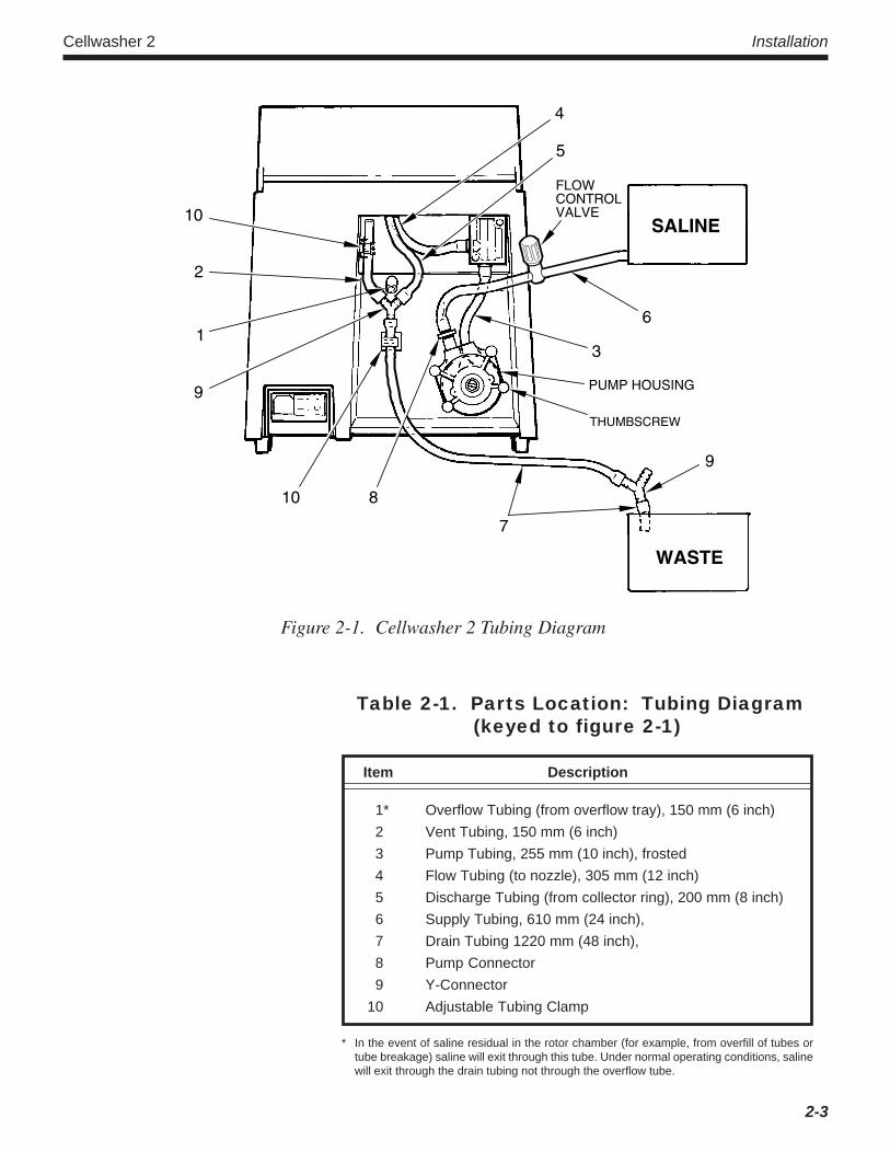
The Cellwasher 2 comes with the tubing already connected to theinstrument, but not installed in the peristaltic pump (do not openthe tubing replacement kit, save it for future use). To completethe tubing installation, unwrap the bundle of tubing at the back ofthe instrument and, referring to figure 2-1 and table 2-1, installthe tubing according to the procedure that follows.
! W A R N I N GThe receptacle used should
be a grounded 3-wire system. If it isnot, the equipment must be groundedto reduce the possibility of electricalshock.
Cellwasher 2 Installation
2-3
Table 2-1. Parts Location: Tubing Diagram(keyed to figure 2-1)
Item Description
1* Overflow Tubing (from overflow tray), 150 mm (6 inch)2 Vent Tubing, 150 mm (6 inch)3 Pump Tubing, 255 mm (10 inch), frosted4 Flow Tubing (to nozzle), 305 mm (12 inch)5 Discharge Tubing (from collector ring), 200 mm (8 inch)6 Supply Tubing, 610 mm (24 inch),7 Drain Tubing 1220 mm (48 inch),8 Pump Connector9 Y-Connector
10 Adjustable Tubing Clamp
* In the event of saline residual in the rotor chamber (for example, from overfill of tubes ortube breakage) saline will exit through this tube. Under normal operating conditions, salinewill exit through the drain tubing not through the overflow tube.
5
PUMP HOUSING
THUMBSCREW
6
10 8
7
9
10
2
1
9
WASTE
SALINE
4
3
FLOWCONTROLVALVE
Figure 2-1. Cellwasher 2 Tubing Diagram

Installation SORVALL® Centrifuges
2-4
1. Unscrew the four knurled thumbscrews from the peristaltic pump,and remove the front half of the pump housing (do not removethe pump roller assembly).
2. Turn the roller assembly so that one of the rollers is in the 11o'clock position.
3. Position the 255 mm (10 inch) frosted pump tubing (with pumpconnector) in front of the pump so that the connector is posi-tioned just above the left side of the pump, then without turningthe roller assembly, route the pump tubing around the rollers.
4. Pull up on the two ends of the pump tubing to fit the tubingbetween the pump housing and the lower roller.
NOTE Do not try to fit the pump tubing with a sharp object, thiscould puncture the tubing.
5. With the pump tubing properly positioned in the back half of thepump housing, reinstall the front half of the housing. Gentlystretch the ends of the pump tubing to eliminate slack whilefitting the front half of the housing in place.
6. Visually check to make sure that the front half of the housing isproperly aligned and fully seated against the back half (a gapindicates that the pump tubing is pinched; if so, remove the fronthalf of the housing and repeat steps 3 through 6).
7. Install the four thumbscrews and hand-tighten.
8. Check the pump tubing installation by turning the roller assem-bly shaft counterclockwise using pliers (the rollers should rotatesmoothly without pinching tubing).
9. If the 610 mm (24 inch) supply tubing is too long, cut it to anappropriate length, then slide the flow control valve (catalognumber 12925, supplied) onto the supply tubing, and connect theend of the supply tubing to a saline supply reservoir.
NOTE The preferred location for the saline supply is either at orabove instrument level. If, at some later time, the salinereservoir is moved from its original location, recheck thesaline volume by priming the system as directed inChapter 3, Operation, Priming the System.
10. Make sure the drain tubing flows downward to an open sink,drain, or waste receptacle because drainage is accomplished bygravity. Use the shortest length of drain tubing possible (if the1220 mm (48 inch) tubing is too long, cut it to an appropriatelength) and make sure the drain tubing is positioned so there isno upward travel to result in a "trap" for collected waste fluid.
W A R N I N GSaline solution from some
manufacturers contain sodium azideas a preservative. If this solution isdischarged directly down the drain,explosive azide salts may form asthe sodium azide reacts with theplumbing. Check with your saline sup-plier before discharging saline fromthe Cellwasher 2 into a drain.
!

Cellwasher 2 Installation
2-5
11. Ideally, the drain tubing should be positioned so that it can notbecome immersed in collected waste fluid. However, if there is apossibility that the drain tubing will become immersed in wastefluid, cut the drain tubing at a convenient point near the wastereceptacle and insert the Y-Connector. Always insert a Y-Con-nector in the drain line when using a waste receptacle.
NOTE The Y-Connector prevents pressure from building up inthe drain tubing due to submerged tubing or air block-age. Failure to vent the drain tubing by installing the Y-Connector can result in improperly decanted samples.
12. If necessary, use additional tubing and connectors from theTubing Kit shipped with the Cellwasher 2 to supply saline anddischarge waste properly.
Rotor and Distributor Installationa. DA-12 Dual Angle Rotor and Rotating
Bowl Installation
1. Open the lid of the Cellwasher 2.
NOTE There may be one or more holes in the stainless steelrotating bowl. The holes are for balancing purposes onlyand will not affect the performance of the rotating bowl.
2. Position the rotating bowl assembly (catalog number 12796,supplied) over the motor drive shaft. Align the two drive pinsin the bowl with the slot in the drive shaft (see figure 2-2).Slide the bowl down the drive shaft until the two pins in thebowl engage the rubber drive ring. Press the bowl downfirmly.
3. Slide the DA-12 Rotor (catalog number 04285, supplied)over the drive shaft and lower it gently into the bowl.
4. Hold the edge of the bowl and turn the rotor slowly until thedrive pins in the bowl engage the rotor and the rotor dropsdown onto the bottom of the bowl.
b. Distributor Installation
Place the Distributor (catalog number 43260, supplied) over therotor knob (see figure 2-3). Turn the distributor until its threepins engage the three holes in the rotor. Press the distributordown until it is completely seated on the rotor.
C A U T I O NIf the rotating bowl assem-
bly, rotor, and distributor are notinstalled properly, damage to the in-strument could result. Beforeoperating the Cellwasher 2:
• Make sure the drive pins in rotat-ing bowl are engaged in the rubberdrive ring and in the rotor.
• Make sure the distributor is firmlyseated on the rotor with the dis-tributor pins completely engagedin the rotor (see figure 2-3).
!

Installation SORVALL® Centrifuges
2-6
Figure 2-3. Distributor Installation
DISTRIBUTOR
CANNULA
DISTRIBUTORPIN
ROTORKNOB
DA-12ROTOR
Figure 2-2. Stainless Steel Rotating Bowl Installation
MOTOR DRIVESHAFT
SLOT
ALIGNMENT
STAINLESS STEELROTATING BOWLASSEMBLY
DRIVE PINS

Cellwasher 2 Installation
2-7/2-8
W A R N I N GResults may be affected if
tubes are not within the specifica-tions provided in Chapter 1 on page1-3. Using tubes of inadequatestrength could result in tube break-age: sample and test results will belost, the rotor and distributor could bedamaged, and cleanup will be re-quired. During cleanup, contact withglass fragments could result in per-sonal injury.
!
Figure 2-4. Tube Placement for Balancing Less Than Twelve Tubes
EIGHT
Rotor Loading and BalancingThe Cellwasher 2 can process any balanced load up to twelve tubes.When using less than a full complement of tubes, place the tubes inopposing compartments to ensure that the rotor is symmetricallybalanced (see figure 2-4). The volume of saline delivered throughthe distributor will be the same; at the locations without tubes, thesaline will be dispensed into the basin and drained off. Read theWARNING.
TENNINE
SIXFOUR
THREETWO
= TUBE
= EMPTY

Installation SORVALL® Centrifuges
2-8

Cellwasher 2 Operation
Chapter 3: OPERATIONThis chapter describes the controls, indicators and operating procedures for the SORVALL® Cellwasher 2.
Controls and IndicatorsAll controls and indicators for the Cellwasher 2 are located on thefront panel keyboard, except for the main power switch and theremote saline flow control valve. The sensor-touch controls registercommands visually and/or audibly.
Power to the instrument is controlled by a switch located in thelower right hand corner of the Cellwasher 2, beneath the keyboard.The symbol "l" indicates ON, while the symbol "O" indicates theOFF position. Switching the power off erases any manually pro-grammed spin times from the memory.
Table 3-1 lists and describes the controls and indicators that can befound on the front panel. Figure 3-1 identifies each item and showsthe location on the keyboard.
Item Name Acceptance Signal Function
1 AUTO LED* Lights up, Selects AUTO run mode for automatic washaccompanied by one beep. cycle.
2 HIGH LED* lights up, Selects HIGH speed run for duration of timeaccompanied by one beep. selected, or indefinitely if HOLD is selected.
3 LOW LED* lights up, Selects LOW speed run for duration of timeaccompanied by one beep. selected; HOLD is not to be selected.
4 CHECK LED* lights up, When in AUTO mode only, stops at the endaccompanied by one beep. of any step in the wash cycle to allow verifi-
cation of procedure.
5 CYCLE Panel key illuminates, Selects 1, 2, 3 or 4 wash cycles during thedigital cycle display AUTO mode.accompanied by one beep.
Table 3-1. Cellwasher 2 Controls and Indicators(keyed to Figure 3-1)
*LED, or light emitting diode, refers to the small amber light adjacent to the panel button.(continued)
3-1
! W A R N I N GThe SORVALL Cellwasher 2
is intended to be used in strict accor-dance with The American Associationof Blood Banks' guidelines defined inthe most recent edition of the AABBTechnical Manual (published by AABBPress. Bethesda, MD).

Operation SORVALL® Centrifuges
Item Name Acceptance Signal Function
6 CYCLE Displays the number of wash cyclesDISPLAY selected in the AUTO mode.
7 TIME Displays the time selected for AUTO,DISPLAY HIGH, or LOW mode in seconds.
8 TIME Digital time display, In HIGH or LOW mode only, selectsaccompanied by one beep. duration of centrifugation time in seconds.
9 START LED* lights up, Starts the mode selected.accompanied by one beep.
10 STOP LED* lights up, Stops the spin in progress. In AUTO,accompanied by one beep. HIGH, or LOW mode, the program will
return to conditions at the start of the run.
11 PRIME Single beep. Primes the pump for 6 seconds.
12 AG Single beep. Agitates the rotor for 5 seconds toresuspend cell button.
13 CLEAR Single beep. In HIGH or LOW mode only, clearsdigital display so that time can be reset.
14 ALARM In AUTO mode only, turns off the alarm.OFF
15 STEP In AUTO mode only, bypasses one stepat a time in the wash cycle for each pushof the button.
16 HOLD Single beep. In HIGH mode only, sets the centrifugeto spin indefinitely; not to be selected inLOW mode.
17 ALARM Single beep, ALARM In AUTO mode only, activates an alarmlights up. that sounds at the end of the cycle.
18 SALINE SALINE lights up. Lights up when saline supply isinterrupted during AUTO fill.
19 LID LED* lights up.** Opens the lid latch at the end of a run.
20 ALARM ALARM lights up. In AUTO mode only, lights up to indicatethe alarm will sound at the end of the run.
Table 3-1. Cellwasher 2 Controls and Indicators (continued)
*LED, or light emitting diode, refers to the small amber light adjacent to the panel button.**The Cellwasher 2 can only be opened when the LID light is illuminated.
3-2

Cellwasher 2 Operation
Figure 3-1. Cellwasher 2 Controls and Indicators
* 100V 50Hz models perform 90-second wash cycles.
Principles of OperationThe SORVALL® Cellwasher 2 has three modes of operation: AUTO,HIGH, and LOW. In the AUTO mode, the washing steps of theCoomb's Procedure are performed automatically. In the HIGH andLOW modes, the Cellwasher 2 spins at a fixed speed (see Chapter 1,Cellwasher 2 Specifications, page 1-2).
NOTE The Cellwasher 2 is not designed to be able to automati-cally separate donor whole blood to create the 2 to 5%red blood cell/saline suspension that is required forwashing cells. The Cellwasher 2 may, however, be op-erated as a centrifuge to manually separate red bloodcells from whole blood (refer to b. HIGH and LOWModes on page 3-4). To prevent loss of blood sampleand avoid the subsequent blood cleanup required, donot attempt to use the AUTO mode to separate wholeblood.
a. The AUTO Mode
In the AUTO mode, the Cellwasher 2 performs a 80-second washcycles* that include the following steps: fill, high speed spin,decant, and agitate. The AUTO mode proceeds automaticallythrough the number of wash cycles selected, unless interruptedby the operator or by the SALINE alarm.
3-3

Operation SORVALL® Centrifuges
The operator can interrupt the AUTO mode at any point to check theprogress of the wash cycle by pressing the CHECK button. When theCHECK button is activated, the Cellwasher 2 will stop at the end ofthe washing step in progress (fill, spin, or decant).
The instrument may also stop if the saline supply is interrupted. TheSALINE alarm will sound, and the cycle in progress will stop afterthe filling step. To restart the instrument, the pump must be primeduntil the saline flow is continuous (see Auto Operation, step b.SALINE alarm, page 3-8). When the Cellwasher 2 is restarted, itbegins at the next step of the wash cycle – the high speed spin.
The information programmed into the Cellwasher 2 at the start of theAUTO cycle remains in memory until the POWER switch is turnedoff.
b. HIGH and LOW Modes
NOTE The HIGH speed mode allows the Cellwasher 2 to beused as a centrifuge to separate red blood cells fromdonor whole blood, for use in the creation of the 2 to 5%red blood cell/saline suspension that is required forwashing cells. To do so, fill tubes with the desired pro-portions of whole blood and saline, then perform a 30 to60 second run in the HIGH speed mode according tostandard protocols.
The HIGH and LOW modes are used for agglutination spins. Thesespins are preceded by a 5 second agitation to allow reagent andsample to mix. After agitation, the samples are spun at a constantrate of speed for the amount of time selected. The spin time pro-grammed by the operator remains in the memory for that mode,appearing automatically in the digital TIME display whenever thatmode is selected. Once the run begins, the TIME displays countsdown the spin time in seconds to zero. At the end of the spin, therotor will come to a stop. The Cellwasher 2 lid cannot be openeduntil the light next to the LID button is illuminated.
NOTE Depending on run conditions and component variabilityfrom instrument to instrument, the rotor may still berotating slowly after the LID light is illuminated.
3-4

Cellwasher 2 Operation
Tube Selection and UseThe Cellwasher 2 is designed to use either 5 ml 12 x 75 mm, or 3 ml 10 x75 mm*, glass centrifuge tubes (saline flow must be adjusted to one sizetube or the other). In normal operation, tubes are subjected to significantstress, making the use of high-strength centrifuge tubes necessary to avoidtube breakage. The Cellwasher 2 spins tubes at a 45° angle with tubewalls point-loaded and otherwise unsupported. Maximum RCF gener-ated may be as high as 1365 g (948 g in 50 Hz operation), and adequatetubes would typically be strength-rated for an even higher g-force, as tubemanufacturers' strength ratings are based on the tubes being fully sup-ported.
Use only centrifuge tubes that meet the following criteria.
Tube Material . . . . . . . . . . . . . . . . . . . . . . . . Type 1, class A borosilicateor equivalent high-strengthrolled glass (such as Pyrex®)
Tube Style . . . . . . . . . . . . . . . . . . . . . . . . . Round bottom, thick walled,rimless (no flange or bead)
Tube Size: Volume (all places) . . . . . . . . . 5 ml or 3 ml*Diameter . . . . . . . . . . . . . . . . . 12 mm +0.0/–0.5 (5 ml)
10 mm +0.0/–0.5 (3 ml)*Length . . . . . . . . . . . . . . . . . . . 75 mm ±1.5Wall Thickness . . . . . . . . . . . . 0.9 mm ±0.1
NOTE As additional criteria, do not use tubes that have beendropped, scratched, or that have a visible defect, asthey may not be able to withstand centrifugation.
Be advised that, even if you do not intend to reuse tubes, you mayfind that centrifuge-rated tubes of adequate strength are often la-beled reusable, not disposable. SORVALL® 5 ml 12 x 75 mm Pyrex®
tubes (Catalog Number 03102, 50/box) and SORVALL® 3 ml 10 x75 mm Pyrex® tubes (Catalog Number 03100, 50/box) are notsupplied, but are recommended for use in the Cellwasher 2.
* Before using 3 ml, 10 mm diameter tubes, a set of Adapter Clips (Catalog No. 04330, 12/pkg., supplied) must be installed on the DA-12 Rotor.
! W A R N I N GTubes must be able to with-
stand up to 1365 g (948 g in 50 Hzoperation) when run at a 45° anglewith tube walls point-loaded and other-wise unsupported. Using tubes of in-adequate strength could result in tubebreakage: sample and test results willbe lost, the rotor and distributor couldbe damaged, and cleanup will be re-quired. During cleanup, be aware thatglass fragments are sharp, and con-tact could result in personal injury.
3-5

Operation SORVALL® Centrifuges
Priming the System & AdjustingSaline Fill VolumeNOTE If sterilization is required, follow the Decontamination
procedure in Chapter 4 on page 4-2, then prime thesystem as described below.
The Cellwasher 2 must be primed and adjusted using the followingprocedure at installation, and whenever the saline supply reservoiror the tubing is changed.
NOTE When the saline flow is interrupted, prime the Cellwasher2 as described in Auto Operation, step b. SALINE alarm,page 3-8.
To Prime the System:
1. Open the lid (press LID button).
2. Select: MODE CYCLE
AUTO 2 ■■■■■ ■■■■■
3. Holding a graduated cylinder under the saline dispenser in thelid, press:
CMD
PRIME ■■■■■
NOTE If air bubbles remain in the tubing, repeat the PRIMEcommand. Air bubbles may cause uneven distribution ofsaline in the test tubes.
4. Once air bubbles have been removed, empty the graduated cylin-der and repeat step 3 to check total saline volume. If an adjustedtotal fill volume (based on tube fills) has previously been deter-mined, compare the collected volume to that volume; if not,initial recommended coarse-adjust total volumes are 54 ml for12 mm (5 ml) tubes, or 36 ml for 10 mm (3 ml) tubes.
5. If total volume is not correct, adjust the flow control valve (turncounterclockwise to allow more saline or clockwise to allowless), then repeat steps 3 and 4 until the desired total volume isobtained. This completes coarse-adjustment based on nominaltotal volume; a fine-adjustment based on tube fills is still re-quired.
6. Place 12 tubes in the DA-12 rotor, close the lid, press START,and then press CHECK. After filling is complete, the lid lightwill come on. Press the LID button, open the lid and check thesaline level in each tube.
FLOW CONTROLVALVE (located on
saline supply tubing)
3-6

Cellwasher 2 Operation
7. Fine-adjust saline volume based on tube fills as follows:
Fine-Adjusting Saline Fill VolumeBased On Tube Fills
This adjustment procedure is required when the system is initially setup, when priming the system, or whenever saline fill volume adjust-ments are required.
NOTE Correct tube fills are necessary for proper cell washing;we recommend that you check fill volume periodically.Fill volume should also be checked whenever the salinesupply reservoir is moved or replaced.To check, install tubes with samples in all 12 places,start an AUTO run, and press CHECK. The Cellwasher 2will stop after the fill step – open the lid and examine thelevel of saline in each tube. Fill volume is consideredacceptable if:• When using the recommended tubes (page 3-5), the
level of saline in the highest tube fill is between 5 and 8mm (0.2 and 0.3 inch) from the top of the tube.
• the difference between the highest fill tube and lowestfill tube is not more than 10 mm (0.4 inch).
Using a graduated cylinder (following the procedure on the previouspage), first adjust the flow control valve to the previously-deter-mined adjusted total fill volume (if an adjusted total fill volume hasnot yet been established, set the volume to 54 ml for 12 mm diameter[5 ml] tubes, or to 36 ml for 10 mm diameter [3 ml] tubes). Afteradjusting to achieve the desired total fill volume, fine-adjust thevolume based on tube fills.
Install tubes in all 12 places, and after filling, check each tube todetermine the highest tube fill –the highest fill should be between 5and 8 mm (0.2 and 0.3 inch) from the top of the tube when recom-mended tubes are used – adjust the flow control valve and recheckfills as required. After the highest tube fill is correct, make sure that thedifference between the highest tube fill and the lowest tube fill is notmore than 10 mm (0.4 inch), equating to a maximum variance ofapproximately 0.7 ml in 12 mm diameter tubes, or 0.45 ml in 10 mmdiameter tubes – troubleshoot if the fill variance is too great.
If, after initially coarse-adjusting the total fill volume (to 54 or 36ml), the flow control valve had to be readjusted based on tube fills,again use a graduated cylinder to measure the new adjusted total fillvolume and record the new value to use as an initial coarse-adjust-ment point for subsequent checks (volume adjustments will con-tinue to change due to tube lot tolerances and normal changes tosystem flow over time).
5 mm 8 mm
1. Fine-adjust thesaline fill volumeuntil the levelof saline in thehighest tube fillis between 5 &8 mm from thetop of the tube.
TOP OF TUBE
FILL RANGE
HIGHEST FILL ISTO BE WITHIN
2. Make sure thatthe differencebetween thehighest tube filland the lowesttube fill does notexceed 10 mm.
HIGHEST FILL10 mm RANGEALL FILLS ARETO BE WITHIN
MINIMUM LINE–LOWEST FILLTO BE ABOVE
3-7

Operation SORVALL® Centrifuges
Auto Operationa. The basic operating sequence in the AUTO mode is as follows:
1. Press the LID button to open the lid.
2. Install the rotor, tubes, and distributor as described in Chap-ter 2, Installation.
3. Close the lid.
4. Select: MODE CYCLE
AUTO 1-4 ■■■■■
5. For an audible signal at the end of the run, press ALARMON.
6. Press START to begin the run.
NOTE If you wish to check for proper fill, press CHECK afterbeginning the run. At the end of the fill step, theCellwasher 2 will stop. Examine the level of saline ineach tube. Fill is considered acceptable if:• When using the recommeded tubes (page 3-5), the
level of saline in the highest tube fill is between 5 and 8mm (0.2 and 0.3 inch) from the top of the tube.
• the difference between the highest fill tube and lowestfill tube is not more than 10 mm (0.4 inch).
Press START to continue run.
7. At the end of the run, if the alarm sounds, press ALARMOFF to turn off the alarm.
8. Once the lid LED is illuminated, press LID to open the lid.
b. SALINE alarm – this alarm will sound during the filling step ifthe saline supply is interrupted. To deactivate the alarm andcorrect the problem, prime the Cellwasher 2 as follows:
1. Open the lid (press LID button).
2. Holding a graduated cylinder under the saline dispenser inthe lid, press:
CMD
PRIME ■■■■■
NOTE The SALINE alarm will not shut off until the PRIMEbutton is pressed.
! W A R N I N GDuring operation, never
lean on or move the instrument, keepthe defined clearance area clear ofall objects (including all hazardousand flammable materials), and do notwork within the clearance area (seeLocation in Chapter 2).
3-8

Cellwasher 2 Operation
3. Close the lid and press START to continue the wash cycle inprogress.
NOTE The SALINE alarm may also indicate broken or ob-structed tubing. If the saline reservoir is adequate, checkthe tubing. Clean or replace tubing if necessary (seeChapter 4, Maintenance).To ensure adequate washing, perform one additionalwash cycle at the completion of the cycles in progress.
c. During AUTO operation, the following features may also beused:
• CHECK button – the automatic wash cycle can be checkedafter any step (fill, spin, or decant) by pressing the CHECKbutton during that step. The Cellwasher 2 will automaticallystop at the end of the step in progress, and the lid may then beopened. After checking the tubes, close the lid and pressSTART to continue run.
• STOP button – when STOP is pressed, the run in progresswill stop immediately. When the LID light goes on, the lidmay be opened. When the Cellwasher 2 is restarted, it willbegin the programmed cycle over again unless steps arebypassed (see STEP button, Table 3-1).
• STEP button – if the AUTO mode is interrupted by a STOPcommand, it will restart at the beginning of the programmedrun. To move the sequence ahead (to avoid refilling tubes forinstance), press the STEP button once for each step in thecycle to be bypassed.
3-9
Operation SORVALL® Centrifuges
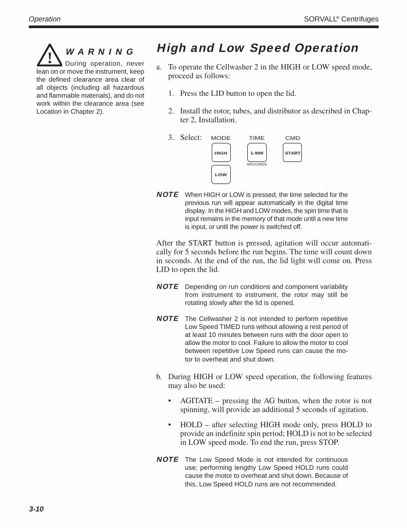
High and Low Speed Operationa. To operate the Cellwasher 2 in the HIGH or LOW speed mode,
proceed as follows:
1. Press the LID button to open the lid.
2. Install the rotor, tubes, and distributor as described in Chap-ter 2, Installation.
3. Select: MODE TIME CMD
HIGH 1-999 START
SECONDS
LOW
NOTE When HIGH or LOW is pressed, the time selected for theprevious run will appear automatically in the digital timedisplay. In the HIGH and LOW modes, the spin time that isinput remains in the memory of that mode until a new timeis input, or until the power is switched off.
After the START button is pressed, agitation will occur automati-cally for 5 seconds before the run begins. The time will count downin seconds. At the end of the run, the lid light will come on. PressLID to open the lid.
NOTE Depending on run conditions and component variabilityfrom instrument to instrument, the rotor may still berotating slowly after the lid is opened.
NOTE The Cellwasher 2 is not intended to perform repetitiveLow Speed TIMED runs without allowing a rest period ofat least 10 minutes between runs with the door open toallow the motor to cool. Failure to allow the motor to coolbetween repetitive Low Speed runs can cause the mo-tor to overheat and shut down.
b. During HIGH or LOW speed operation, the following featuresmay also be used:
• AGITATE – pressing the AG button, when the rotor is notspinning, will provide an additional 5 seconds of agitation.
• HOLD – after selecting HIGH mode only, press HOLD toprovide an indefinite spin period; HOLD is not to be selectedin LOW speed mode. To end the run, press STOP.
NOTE The Low Speed Mode is not intended for continuoususe; performing lengthy Low Speed HOLD runs couldcause the motor to overheat and shut down. Because ofthis, Low Speed HOLD runs are not recommended.
! W A R N I N GDuring operation, never
lean on or move the instrument, keepthe defined clearance area clear ofall objects (including all hazardousand flammable materials), and do notwork within the clearance area (seeLocation in Chapter 2).
3-10

Cellwasher 2 Operation
W A R N I N GIn the event of tube break-
age, be careful to avoid personal in-jury due to sharp fragments. Alwaysmake sure all glass is removed, in-cluding any pieces that may havebecome lodged in the overflow anddrain tray exits and tubing. Also, makesure that the overflow container isempty before resuming use.
!
! C A U T I O NThe distributor is balanced
as an assembly. In extreme cases, ifit must be disassembled for cleaning,all parts must be marked for position/orientation so that it will be in balanceafter reassembly.
Tube BreakageNecessary Action to Prevent InstrumentMalfunction
Tube breakage followed by an inadequate cleanup can be a majorcause of instrument malfunction. Residual glass fragments can blockdrains and cannulas, leading to flooding of internal components andan accelerated buildup of encrusted salt/media. Every time tubebreakage occurs, or if fluid exits through the overflow tubing orappears from under the cabinet, a thorough cleaning and inspectionshould be completed before continued operation. Disconnect powerand decontaminate the Cellwasher 2 as required, then perform thecleaning and inspection as follows:
1. In the lid, separate the collector ring from the retaining ring byremoving the four mounting screws and stepwashers (for partsidentification, refer to Figure 4-1 on page 4-3). Clean all glassand residue from both sides of the collector ring, and from insideits drain nozzle and the connected discharge tubing. Using wa-ter, be sure the collector ring drains freely through the tubing – ifnot, clear blockage and recheck as required. Clean the surface ofthe retaining ring and its O-ring, then reassemble, making surethe collector ring is fully seated on the retainer ring beforesecuring it with screws and stepwashers.
2. Remove and clean the distributor assembly, the rotor, and therotating bowl assembly. On the distributor assembly, make surethat no fragments have fallen down inside the center area, toensure that cannulas will not become obstructed, and make surecannulas have not been damaged. On the rotating bowl assem-bly, make sure that no fragments have become situated betweenparts by checking that the lift plate mechanism slides up anddown freely.
3. Clean the wet guard (black plastic liner) that covers the chamberand top deck, then remove it. Locate the small white overflowtray, which is positioned directly under, and obstructed by, thedecant coil (a black ring around the top of the motor assembly).Clean all glass and residue from the overflow tray, and frominside its drain nozzle and the connected overflow tubing. Usingwater, be sure the overflow tray drains freely through the tubing(being careful not to overflow the tray, if drainage is still im-paired) – if not, clear blockage and recheck as required.
4. Reinstall the wet guard, then, being sure to engage the drive pinson each, reinstall the rotating bowl assembly, the rotor, and thedistributor assembly. If the problem recurs, contact Kendro Ser-vice.
3-11
Operation SORVALL® Centrifuges
Momentary Power InterruptionIf a momentary power interruption occurs when a run is in progresswith the rotor spinning, it can take up to ten seconds before the rotorcomes to a stop. Do not open the lid with the rotor spinning.
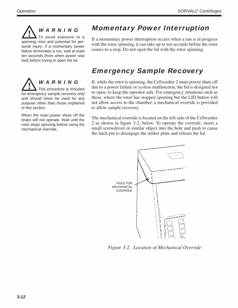
Emergency Sample RecoveryIf, while the rotor is spinning, the Cellwasher 2 main power shuts offdue to a power failure or system malfunction, the lid is designed notto open, to keep the operator safe. For emergency situations such asthese, where the rotor has stopped spinning but the LID button willnot allow access to the chamber, a mechanical override is providedto allow sample recovery.
The mechanical override is located on the left side of the Cellwasher2 as shown in figure 3-2, below. To operate the override, insert asmall screwdriver or similar object into the hole and push to causethe latch pin to disengage the striker plate and release the lid.
W A R N I N GTo avoid exposure to a
spinning rotor and potential for per-sonal injury, if a momentary powerfailure terminates a run, wait at leastten seconds (from when power waslost) before trying to open the lid.
!
! W A R N I N GThis procedure is included
for emergency sample recovery onlyand should never be used for anypurpose other than those explainedin this section.
When the main power shuts off thebrake will not operate. Wait until therotor stops spinning before using themechanical override.
HOLE FORMECHANICAL
OVERRIDE
Figure 3-2. Location of Mechanical Override
3-12

Cellwasher 2 Maintenance
4-1
Chapter 4: MAINTENANCEThis chapter describes routine maintenance procedures that should be performed on a regular basis, withthe specific time interval or duty cycle determined by the user, and based on product use. It is also theresponsibility of the user to make certain that these procedures are followed whenever necessary. If furtherservice is needed, contact Kendro or your local representative for SORVALL® products.
! W A R N I N GThere are no user-service-
able items inside the Cellwasher 2.Due to the hazards involved, repairshould only be attempted by a quali-fied technician who is familiar withelectronics and trained in the servic-ing of this product.
! W A R N I N GContinued use of a rotor
with tube holder band gaps greaterthan 2 mm, or that has had bandscompressed to close the gaps, cancause tube breakage, possibly result-ing in instrument damage or personalinjury.
Preventive MaintenanceThe following preventive maintenance checks and cleaning proce-dures should be performed regularly. If etiologic or biologicallyhazardous materials are processed in the Cellwasher 2, be sureappropriate decontamination procedures have been followed beforeinspecting or cleaning the instrument.
a. Inspection
• Inspect the vents on the bottom of the Cellwasher 2 to be surethey are not blocked, and remove any obstructions.
• Check all sealing surfaces, tubing, liners, and the collecting ringassembly for cleanliness and good condition.
• Inspect the distributor, rotor, and stainless steel rotating bowl:
1. Remove the distributor from the top of the rotor; check forcracks and make sure cannulas are not bent, damaged, orclogged. From underneath, make sure the metal clip thatholds the distributor to the rotor is not cracked or broken.
2. Remove the DA-12 rotor from the rotating bowl assembly.Make sure that the rotor does not wobble on its base. Makesure that the pivot pin at the top of each tube holder is notloose. Also, check the gaps in the tube holder bands – gapsmay widen over time due to centrifugal force, and the rotorshould not be used if the gaps become greater than 2 mm. Donot compress the tube holder bands to close the gaps; bandsare precisely shaped to support tubes during centrifugation,and tube support will be compromised if the bands aredeformed in this manner (read the WARNING).
3. Remove the stainless steel rotating bowl assembly (located inthe rotor chamber, directly beneath the rotor), and inspect therotating bowl assembly for signs of cracks or corrosion.
NOTE If inspection reveals that any part of the Cellwasher 2 isnot functioning properly, do not use the instrument untilit is repaired.

Maintenance SORVALL® Centrifuges
4-2
b. Cleaning
• Clean the Cellwasher 2 cabinet with a damp cloth and milddetergent.
• Wipe up spills from the interior and exterior whenever theyoccur.
• Remove the rotor, distributor, and rotating bowl and wash themwith warm water and mild detergent.
• Remove the collecting ring assembly and tubing for routinecleaning as follows (see figure 4-1):
1. From the back of the instrument, open the adjustable tubingclamp that secures the Y-Connector in place and remove thedischarge tubing from the Y-Connector (see figure 2-1).
2. Remove the four mounting screws and step washers securingthe collecting ring assembly to the lid.
3. Pull the collecting ring assembly away from the lid, and pullthe discharge tubing up through the wet guard (molded blackliner).
4. Disconnect the flow tubing from the spray nozzle in the lidand pull it through the hole in the retainer ring.
5. Separate the collector ring assembly by pulling the collectorring off.
6. Remove discharge tubing and flow tubing, wash with warmwater and mild detergent, and reinstall (see figure 2-1).
7. Wash the retainer ring, O-ring seal, and collector ring withwarm water and mild detergent.
8. To reassemble, place the retainer ring on work surface (smallopening down), and work the O-ring seal around the largeopening of the retainer ring until it is fully seated in thegroove. Then, place the collector ring so that it rests concen-trically over the O-ring seal and press firmly into place.
NOTE Make sure the nozzle for the discharge tubing on thecollector ring aligns with the groove in the wet guard whenthe collecting ring assembly is reinstalled in the lid.
9. Reinstall the collecting ring assembly by reversing steps 1through 4 of this procedure.
NOTE When replacing the four mounting screws, make surethe flat side of each step washer faces the screw head.
! C A U T I O NAll saline solutions have
long term corrosive effects. Routinecleaning and maintenance are es-sential to ensure safe and efficientoperation.

Cellwasher 2 Maintenance
4-3
c. Decontamination
The Cellwasher 2 is intended for use in Coomb's testing and incor-porates the use of human blood. If the Cellwasher 2 has been usedwith other hazardous materials, be aware of all hazards involved anddecontaminate using additional appropriate methods. As a guide, theSORVALL® Product Guide contains descriptions of commonly useddecontamination methods and a chart showing method compatibilitywith various materials. Otherwise, observe Universal Precautionsand proceed as directed on the next page.
! W A R N I N GIf tubes have been broken
in the Cellwasher 2, be aware of thepotential for residual glass fragmentsand take extra precautions.
The Cellwasher 2 is intended for usewith human blood. Always observeUniversal Precautions.
Figure 4-1. Collecting Ring Assembly, Exploded View
STEPWASHER
MOUNTINGSCREW
COLLECTORRING
DISCHARGETUBING
FLOWTUBING
O-RINGSEAL
LID
TO WASTECONTAINER ORT-CONNECTOR
TO FLOWDETECTOR
RETAINERRING
O-RINGGROOVE
COLLECTOR RINGASSEMBLY
SPRAYNOZZLE

Maintenance SORVALL® Centrifuges
4-4
If the Cellwasher 2 is operational
1. Prepare a 3-10% solution of household liquid chlorine bleach.
2. Soak a wash rag or sponge with the bleach solution and gentlywipe the bowl assembly, the wet guard, and the inner portion ofthe Cellwasher 2, making sure all encrusted material is gone. Dothis step twice.
3. Disconnect the supply tubing from the saline supply and set thetubing to draw from the bleach solution.
4. Pump the bleach solution through the Cellwasher 2 for four cycles.
5. Set the tubing to draw from clean water and follow the bleachsolution with 4 to 12 water washes, so that no bleach remains.
6. Reconnect the tubing to the saline supply and follow the waterwashes with four cycles of saline.
7. Check the pH level to make sure it is normal. If not, continuewith saline cycles until pH checks normal.
8. Open the lid, turn the main power switch OFF, and unplug thepower cord. Wipe all parts (including parts inside the lid andchamber, the cabinet, the control panel, and the front surface of themain power switch) with a 70% ethanol solution and allow to dry(do not flood the switch or power cord connector areas).
If the Cellwasher 2 is not operational
1. Turn the power switch OFF, unplug the power cord, and open the lidusing the mechanical override (see page 3-12, Emergency SampleRecovery). Remove tubes (if any) from the DA-12 rotor.
2. Prepare a 3-10% solution of household liquid chlorine bleach.Disassemble the collector ring assembly (see Cleaning, page 4-2);immerse components for 10 minutes in the bleach solution.
3. Remove the discharge tubing, vent tubing, and drain tubingalong with any Y-connectors, draining any excess saline from thepieces. Immerse and completely fill the tubing and connectors inthe bleach solution (try not to leave any air in the tubing); keepthem immersed for 10 minutes.
NOTE Depending on the age or condition of the tubing, as wellas the type or amount of contamination, you may chooseto replace tubing instead of decontaminating it. If so,discard contaminated tubing in an appropriate manner,then, after the instrument has been decontaminated,install a Tubing Replacement Kit (Catalog No. 12977,supplied), following instructions supplied in the kit.

Cellwasher 2 Maintenance
4-5
4. Individually remove the distributor, the DA-12 rotor, and thestainless steel bowl. Immerse the distributor for 10 minutes inthe bleach solution. Wipe the DA-12 rotor and stainless steelbowl using a 70% solution of ethanol, making sure that allencrusted material is gone, then rinse with water. Repeat theethanol wash a second time.
5. Remove the wet guard (black plastic liner) from the chamber.Soak a wash rag or a sponge in the bleach solution and gentlywipe the wet guard and the inner portion of the unit (includingthe nozzle and inside of the lid, the motor shaft and the decantcoil). Make sure that all encrusted material is gone.
6. Make sure a container is positioned to collect fluid from theoverflow tubing. Pouring slowly so that the tray doesn't over-flow, pour some bleach solution into the white plastic overflowtray (below the decant coil) this should drain out freely throughthe overflow tubing. Follow with clean water to rinse.
7. Wipe the entire cabinet, including the control panel and the frontsurface of the main power switch, with 70 % ethanol (do notflood the power switch or power cord connector areas).
8. After 10 minutes in the bleach solution, remove all componentsthat had been soaking and rinse with water several times.
9. Allow all components to dry, then reassemble the unit as before.
NOTE When reinstalling the four mounting screws of the col-lector ring assembly, make sure that the flat side of eachstep washer is against the screw head.
Service Decontamination PolicyIf a Cellwasher 2 requires servicing by Kendro personnel, either atthe customer’s laboratory or at a Kendro facility, comply with thefollowing to ensure the safety of all personnel.
If the Cellwasher 2 has been used with other hazardous materials, beaware of all hazards involved and decontaminate using additionalappropriate methods. As a guide, the SORVALL® Product Guidecontains descriptions of commonly used decontamination methodsand a chart showing method compatibility with various materials.Otherwise, if a Cellwasher 2 requires servicing by Kendro, proceedas follows:
1. Decontaminate the Cellwasher 2 to be serviced, and clean it ofall encrusted material prior to servicing by a Kendro representa-tive or returning it to the Kendro facility. There must be noradioactivity detectable by survey equipment. Decontaminateaccording to the instructions that begin on page 4-3.
Maintenance SORVALL® Centrifuges
4-6
2. Complete and attach a Decontamination Information Certificate(in the back of this manual) to the Cellwasher 2 before servicing.
In addition to those included with in this book, DecontaminationInformation Certificates are available from the local KendroRepresentative or Field Service Engineer. In the event that cer-tificates are not available, a signed, written statement certifyingthat the unit has been properly decontaminated, identifying whatthe contaminants were and outlining the decontamination proce-dures used will be acceptable.
NOTE The Field Service Engineer will note on the CustomerService Repair Report if decontamination was requiredand, if so, what the contaminant was and what proce-dure was used. If no decontamination was required, itwill be so stated.
If a Cellwasher 2 to be serviced does not have a DecontaminationInformation Certificate attached and, in Kendro's opinion presents apotential radioactive or biological hazard, the Kendro representativewill not service the equipment until proper decontamination andcertification is complete.
If the Cellwasher 2 must be returned to a Kendro facility:
1. Contact your Kendro representative to obtain an EquipmentReturn Decontamination Form; be prepared with the productname (Cellwasher 2), serial number and the repairs required.
2. Complete the Equipment Return Decontamination Form andreturn it to Kendro. Upon receipt of a completed form, a Re-turned Material Authorization Number (RMA Number) will beissued to you.
3. With the RMA Number clearly marked on the outside of packag-ing, send the items to the address obtained from your Kendrorepresentative.
NOTE United States federal regulations require that parts andinstruments must be decontaminated before being trans-ported. Outside the United States, check local regulations.
If equipment is received at Kendro facilities without a valid RMANumber on the outside of the shipping container and a completedEquipment Return Decontamination Form on file, the equipmentwill be treated as a potential contamination hazard, and will not beserviced until decontamination certification has been completed.The sender will be contacted for instructions regarding dispositionof the equipment in question; all disposition costs will be borne bythe sender. If contaminated equipment is received at Kendro facili-ties, both the carrier and appropriate authorities shall be notified.

Cellwasher 2 Maintenance
4-7
Parts ReplacementTo order replacement parts, telephone toll-free 800-522-7746 in theUnited States. Outside the United States, contact Kendro or yourlocal representative for SORVALL® products (see back cover for apartial list). Be prepared to supply the product name (Cellwasher 2),serial number, and a description of the parts required.
Tubing ReplacementIf tubing is damaged and must be replaced, install tubing supplied inthe Tubing Replacement Kit (Catalog No. 12977) following installa-tion instructions supplied with the kit.
Fuse ReplacementTo replace the fuse in the power supply adapter:
1. Unplug the power cord.
2. Remove the power cord from the power supply adapter.
3. Slide the clear plastic guard to the left of the power cord connec-tion.
4. Pull out the FUSE PULL lever. The end of the fuse will pop out.
5. Remove the fuse, and replace it with the appropriate slow-blowfuse. (Fuse rating is indicated on rear nameplate).
6. Move the guard to the right, and replace the power cord.
TroubleshootingTables 4-1 through 4-4 contain troubleshooting information forsome common problems that occur during operation of the Cellwasher2. The customer should not attempt any further troubleshooting.
Tables 4-5 through 4-7 contain applications troubleshooting infor-mation which identify possible causes of false negative results, falsepositive results, or inconsistent reaction strength.
! W A R N I N GThere are no user-service-
able items inside the Cellwasher 2.Due to the hazards involved, repairshould only be attempted by a quali-fied technician who is familiar withelectronics and trained in the servic-ing of this product.
Maintenance SORVALL® Centrifuges
4-8
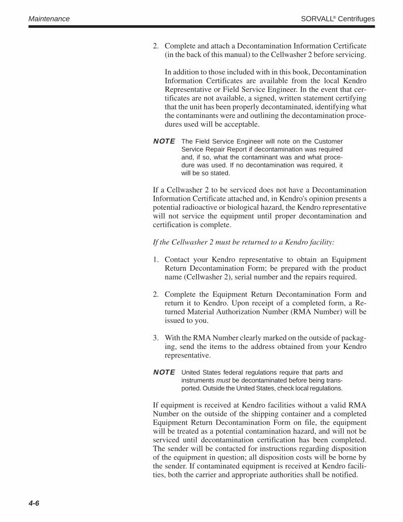
Table 4-1. Troubleshooting Chart: Problem A
Improper saline fill of tubes.
Is saline volume correct?
Is distributor dirty? Are cannulasclogged?
Are tubes the correct length anddiameter?
Replace with tubes of correct lengthand diameter.
Adjust volume (see page 3-7, Fine-AdjustingSaline Fill Volume Based on Tube Fills).
Clean distributor and each cannula.
Contact Kendro Representative.Yes
Yes
No
No
Yes
No
Connect power cord asrequired.
Is instrument plugged in?
No
Yes
Instrument completelyinoperative and displays not
illuminated.
No
Replace fuse. See fuse replacementprocedure on page 4-7.
Is AC line fuse blown?
Yes
Yes
Place power switch in theON position.
NoIs power switch on?
Contact KendroRepresentative
Table 4-2. Troubleshooting Chart: Problem B

Cellwasher 2 Maintenance
4-9
Table 4-3. Troubleshooting Chart: Problem C
Instrument will not operate and displaysare illuminated.
Is lid properly latched? Close lid properly.
Contact Kendro Representative
Yes
No
Table 4-4. Troubleshooting Chart: Problem D(see figures 4-2 and 4-3)
Is decant coil aligned properly?(Alignment is improper if lift plate ringshows abnormal rubbing on one side.)
Does lift plate ring movefreely?
Is the drive ring loose ofdeformed?
Does motor turncounterclockwise?
Contact KendroRepresentative
Align decant coil to be concentricwith motor shaft.
Clean ring – look for glassfragments, rust, salt residue, or
other foreign substances.
Secure or replacedrive ring.
No
Yes
Yes
No
Decant Malfunction.
Faulty clutch – replace.
No
Yes
Yes
No

Maintenance SORVALL® Centrifuges
4-10
Figure 4-2. Location of Decant Coil and Drive Ring
DECANTCOIL
DRIVERING
MOTORSHAFT
BOWL
LIFT PLATE RING
Figure 4-3. Location of Lift Plate Ring

Cellwasher 2 Maintenance
4-11
Table 4-5. Applications Troubleshooting Chart:False Negative Results
False negative results.
Is the red blood cell suspensionconcentration correct (2-5%)?
Was the antiglobulin serumomitted?
Are the reagents no longerreactive due to improper
storage?
Was the reagent contaminatedwith human serum?
Was cell-coating inadequateduring incubation?
Were the samples undercentrifugedin the manual mode?
Contact Kendro Representative
Modify the cell suspensionconcentration.
Repeat the test, notingantiglobulin step.
Repeat the test with fresh reagent.
Repeat the test with fresh reagent.
Increase spin time.
Yes
Yes
Yes
Yes
No
No
No
Yes
No
No
No
Yes
1. Check incubation time.2. Check the volume of reagent added.
Maintenance SORVALL® Centrifuges
4-12
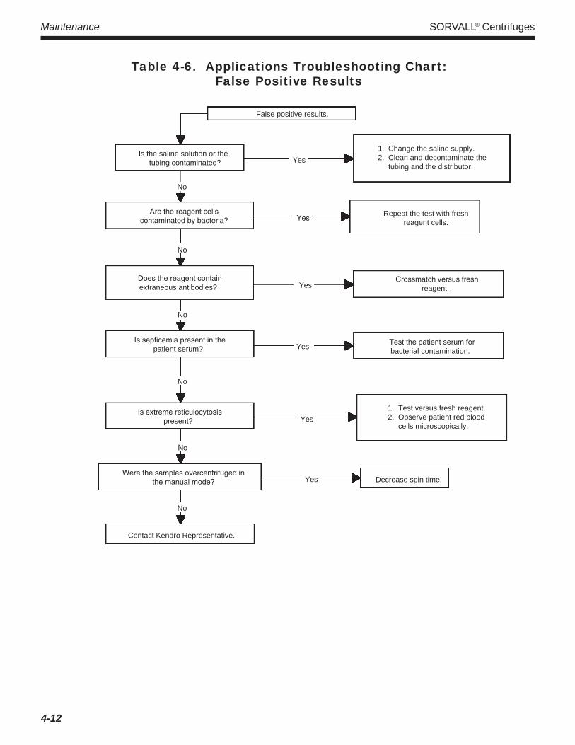
Table 4-6. Applications Troubleshooting Chart:False Positive Results
False positive results.
Is the saline solution or thetubing contaminated?
Are the reagent cellscontaminated by bacteria?
Does the reagent containextraneous antibodies?
Test the patient serum forbacterial contamination.
Is septicemia present in thepatient serum?
Is extreme reticulocytosispresent?
Were the samples overcentrifuged inthe manual mode?
Contact Kendro Representative.
No
No
No
Yes
Yes
No
Yes
Yes
Yes
No
No
Yes
Decrease spin time.
Repeat the test with freshreagent cells.
Crossmatch versus freshreagent.
1. Change the saline supply.2. Clean and decontaminate the tubing and the distributor.
1. Test versus fresh reagent.2. Observe patient red blood cells microscopically.

Cellwasher 2 Maintenance
4-13/4-14
Table 4-7. Applications Troubleshooting Chart:Inconsistent Reaction Strength
Inconsistent reactionstrength from tube to tube.
Were the same number ofcells added to each tube?
Repeat the test, adding thesame number of cells to
each tube.
Was the same amount ofreagent added to each tube?
Is the antiglobulin serumweak or outdated?
Repeat the test, adding thesame amount of reagent to
each tube.
Repeat the test with freshantiglobulin serum.
Contact Kendro Representative.
Yes
No
No
No
Yes
Yes


Cellwasher 2 Appendix
APPENDIX
Appendix SORVALL® Centrifuges
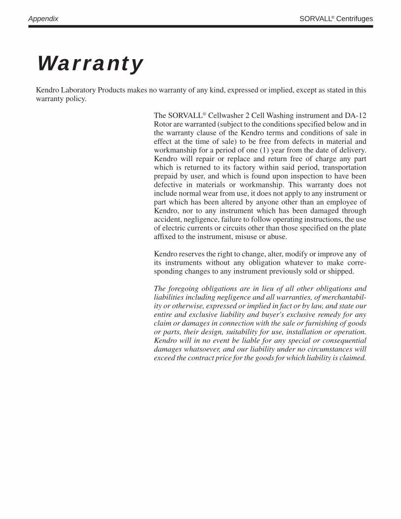
WarrantyKendro Laboratory Products makes no warranty of any kind, expressed or implied, except as stated in thiswarranty policy.
The SORVALL® Cellwasher 2 Cell Washing instrument and DA-12Rotor are warranted (subject to the conditions specified below and inthe warranty clause of the Kendro terms and conditions of sale ineffect at the time of sale) to be free from defects in material andworkmanship for a period of one (1) year from the date of delivery.Kendro will repair or replace and return free of charge any partwhich is returned to its factory within said period, transportationprepaid by user, and which is found upon inspection to have beendefective in materials or workmanship. This warranty does notinclude normal wear from use, it does not apply to any instrument orpart which has been altered by anyone other than an employee ofKendro, nor to any instrument which has been damaged throughaccident, negligence, failure to follow operating instructions, the useof electric currents or circuits other than those specified on the plateaffixed to the instrument, misuse or abuse.
Kendro reserves the right to change, alter, modify or improve any ofits instruments without any obligation whatever to make corre-sponding changes to any instrument previously sold or shipped.
The foregoing obligations are in lieu of all other obligations andliabilities including negligence and all warranties, of merchantabil-ity or otherwise, expressed or implied in fact or by law, and state ourentire and exclusive liability and buyer's exclusive remedy for anyclaim or damages in connection with the sale or furnishing of goodsor parts, their design, suitability for use, installation or operation.Kendro will in no event be liable for any special or consequentialdamages whatsoever, and our liability under no circumstances willexceed the contract price for the goods for which liability is claimed.

Cellwasher 2 Appendix
IndexMaintenance, Preventive, 4-1
Operationauto, 3-8high and low speed, 3-10principles of, 3-3
auto mode, 3-3high and low modes, 3-4
Parts Replacement, 4-7Power Interruption, Momentary, 3-12Preventive Maintenance, 4-1Priming the System, 3-6
Rotor Loading and Balancing, 2-7
Safety Information Page, iiiSaline Fill Volume, 3-6Sample Recovery, Emergency, 3-12Service Decontamination Policy, 4-5Specifications, 1-2
Troubleshooting, 4-7Tube
breakage, 3-11selection and use, 3-5
Tubinginstallation, 2-2replacement, 4-7
Unpacking, 2-1
Accessories Supplied, 1-4Adjusting Fill Volume, 3-6Applications Information, 1-1
Balancing, Rotor, 2-7
Cellwasher 2description, 1-1specifications, 1-2
Cleaning, 4-2Controls and Indicators, 3-1
Decontamination, 4-3Description, 1-1
Electrical Requirements, 2-2Emergency Sample Recovery, 3-12Environmental Conditions, 2-2
Fill Volume, Adjusting, 3-6Fuse Replacement, 4-7
Inspection, 4-1Installation
rotor and rotating bowl, 2-5distributor, 2-5tubing, 2-2
Location, 2-1Loading, Rotor, 2-7

NOTES


Or contact a local representative for SORVALL® brand products. Visit our web site at http://www.kendro.com or http://www.kendro.de
Rev. 01/05
AUSTRIAKendro Laboratory Products GmbHWiegelestraße 4A-1230 ViennaTel.: 43 (1) 801 40-0Fax: 43 (1) 801 40-40e-mail: [email protected]
UNITED KINGDOMKendro Laboratory Products LimitedStortford Hall ParkBishop's StortfordHertfordshire CM23 5GZTel.: 44 (1279) 827700Fax: 44 (1279) 827750e-mail: [email protected]
GERMANY or other EUROPE,MIDDLE EAST, or AFRICA:
Kendro Laboratory Products GmbHRobert-Bosch-Straße 163505 LangenselboldGERMANYTel.: 0800-1-536 376 (Sales)Fax: 0800-1-112 114e-mail: [email protected]
JAPANNihon Kendro Company Ltd.Muroichi Building, 4F1-13-4 MuromachiNihonbashi, Chuo-kuTokyo, Japan 103-0022Tel.: 81-3-3517-1661Fax: 81-3-3517-1664e-mail: [email protected]
INDIAKendro Laboratory Products India Pvt. Ltd.B-2/201 Safdarjung EnclaveNew Delhi, 110029, IndiaTel.: 91 (11) 2618 58 40
91 (11) 2618 48 40Fax: 91 (11) 2618 53 97e-mail: [email protected]
AUSTRALIAKendro Laboratory Products Pty. Ltd.Building 4, 2-6 Orion RoadLane Cove, Sydney, NSW 2066Tel.: 61 (2) 9936 1540Fax: 61 (2) 9427 9765e-mail: [email protected]
SWEDENKendro Laboratory Products Axeb ABBox 437191 24 SollentunaTel.: 46 (8) 585 777 50Fax: 46 (8) 623 15 45e-mail: [email protected]
SWITZERLANDKendro Laboratory Products AGRäffelstrasse 32-PostfachCH-8045 ZürichTel.: 41 (1) 454 12 12Fax: 41 (1) 454 12 99e-mail: [email protected]
FRANCEKendro Laboratory ProductsB.P. 244, Parc Hightec 6Batiment le Meridien9 Avenue du CanadaF-91944 COURTABOEUF CedexTel.: 33 (1) 69 18 77 77Fax: 33 (1) 60 92 00 34e-mail: [email protected]
CHINA, SHANGHAI:Kendro Laboratory Products Shanghai Representative OfficeRoom 22G, Hui Jia BuildingNo. 41 Cao Xi Bei LuShanghai 200030, P.R. ChinaTel.: 86-(21)-5490-0216
86-(21)-5490-0218Fax: 86-(21)-5490-0230e-mail: [email protected]
CHINA, BEIJING:Kendro Laboratory Products Beijing Representative Office8th Floor, Office BuildingHong Kong Macau CenterNo. 2 Chao Yang Men Bei Da JieBeijing 100027, P.R. ChinaTel.: 86-(10)-6501-1573
86-(10)-6501-3810Fax: 86-(10)-6501-4229e-mail: [email protected]
CHINA, HONG KONGor other ASIA PACIFIC:
Kendro Laboratory Products (H.K.) Ltd.Suite 1105, Chinachem Golden Plaza77 Mody Road, Tsimshatsui EastKowloon, Hong KongTel.: 852-2711-3910,
852-2142-3910Fax: 852-2711-3848e-mail: [email protected]
UNITED STATES of AMERICAKendro Laboratory Products275 Aiken RoadAsheville, NC 28804Tel.: 1 (800) 522-7746
1 (828) 658-2711Fax: 1 (828) 665-4330e-mail: [email protected]
CANADA or other countries,including LATIN AMERICA:
Kendro Laboratory Products International Sales275 Aiken RoadAsheville, NC 28804
U.S.A.Tel.: 1 (800) 522-7746
1 (828) 658-2711Fax: 1 (828) 665-4330e-mail: [email protected]