sop l-410
TRANSCRIPT

Standard Operating Procedures L-410

Standard Operating Procedures
L-410
Chapter
Page
Revision
Date
::::
2 0 27.07.2010
PREFACE
In line with the DCA recommendations , the company has reviewed and has began implementing appropriate measures that would reduce the risk of incidents and accidents in our Flight Operations. One of the first measures undertaken by the Training Department was to review and rewrite the SOP which gives us clear, comprehensive view reflective of the company’s operating as well as its training philosophies. The SOPs will supplement the Operation Manual. Company Flight Procedures will be laid down in them; The DCA for the operation of L-410 UVP-E, approves these procedures and the knowledge of their contents is mandatory. It is general policy to standardize procedures and call-outs. The intention of this SOP is to standardise and concur upon a safe and efficient operation, uniformly built to describe the crewmembers area of responsibility so as to achieve the highest standards of flying discipline .It has been designed to enhance safety, to assist crew to manage risk as well as to ensure consistency in the cockpit. In short it is written as a reference for crew to establish working environment required for CRM. Each Flight Crew member must be aware of the duties and responsibilities of others as well as their own. Deviations from the SOP occur for a variety of reasons, intentional deviations and in advert deviations from SOP have been identified as casual factors in many Approach and Landing Accidents (ALAs) It is therefore NOT acceptable for pilots to deviate from SOP intentionally without any valid reason. However, if the situation warrants for such a deviation (e.g. ATC requirements, abnormal conditions etc.), the intended deviation must be pre-fixed with the word “ Non- Standard” before executing the deviation. All other crew members must be informed of such an intended deviation and Pilot In-Command must have complete control over the non-standard procedure at all times. In consequence, personal methods or practices should not be introduced. Adherence to SOP is mandatory. On top of that CRM will never be effective without adherence to SOP. The manuals which had been taken as reference to provide the basis for the writing of the company’s Standard Operating Procedures are as follows:
a. The L-410 UVP-E Airplane Flight Manual which includes operational limitations, aircraft performance in flight, normal procedures and provides information and recommendations on manoeuvres, techniques of flying.
b. The Quick Reference Handbook, edition 4 June 2008, which contains abnormal and emergency check list and performance given in tabulated form.
c. The L-410 UVP-E Aircraft Training Manual The above mentioned manuals will be used as a comprehensive reference manual for Icar Air’s daily flying operations .However , where the Icar Air procedures differs from those stated in manual above mentioned , the company SOP shell supersede. General information, which is not limited to a specific phase of flight such as Crew Duties, Flight Deck Management and Systems operation, will be found in their respective subsections. The responsibilities and duties of an operating crew are detailed in this Subsection Normal procedures relate to a specific phase of flight are found in the subsections relating to that Phase. Normal procedures are listed to follow the normal sequence of events. These include tables that are provided to give a quick reference summary. The Dispatch Deviation Procedures Guide (DDPG)/MEL) document is intended to allow the safe dispatch of aircraft for flight with various deviations to normal configuration permitted and approved by BH DCA.The objective of MEL is to improve aircraft utilisation by minimising delays to aircraft schedules and thereby contribute to a more efficient and economic air transportation without compromising airworthiness requirements and air safety. The aircraft captain will determine if defect is acceptable for further flight. This decision is to be made with due consideration to the aircraft’s operating pattern and crew workload. All crew shall highlight any error, omission or any shortcoming in this SOP and shall direct all quires to the Training Manager and Chief Pilot L-410 UVP-E who is given authority to maintain this document. Any change or amendment to any procedure shall only take effect after being approved by the FOM.
Capt. Zeljko Gvozdenov

Standard Operating Procedures
L-410
Chapter
Page
Revision
Date
::::
3 0 27.07.2010
RECORD OF REVISION
REVISION No.
REVISION DATE
REVISED SUBJECT
INSERTION DATE REVISED BY
Standard Operating Procedures
L-410
Chapter
Page
Revision
Date
::::
4 0 27.07.2010
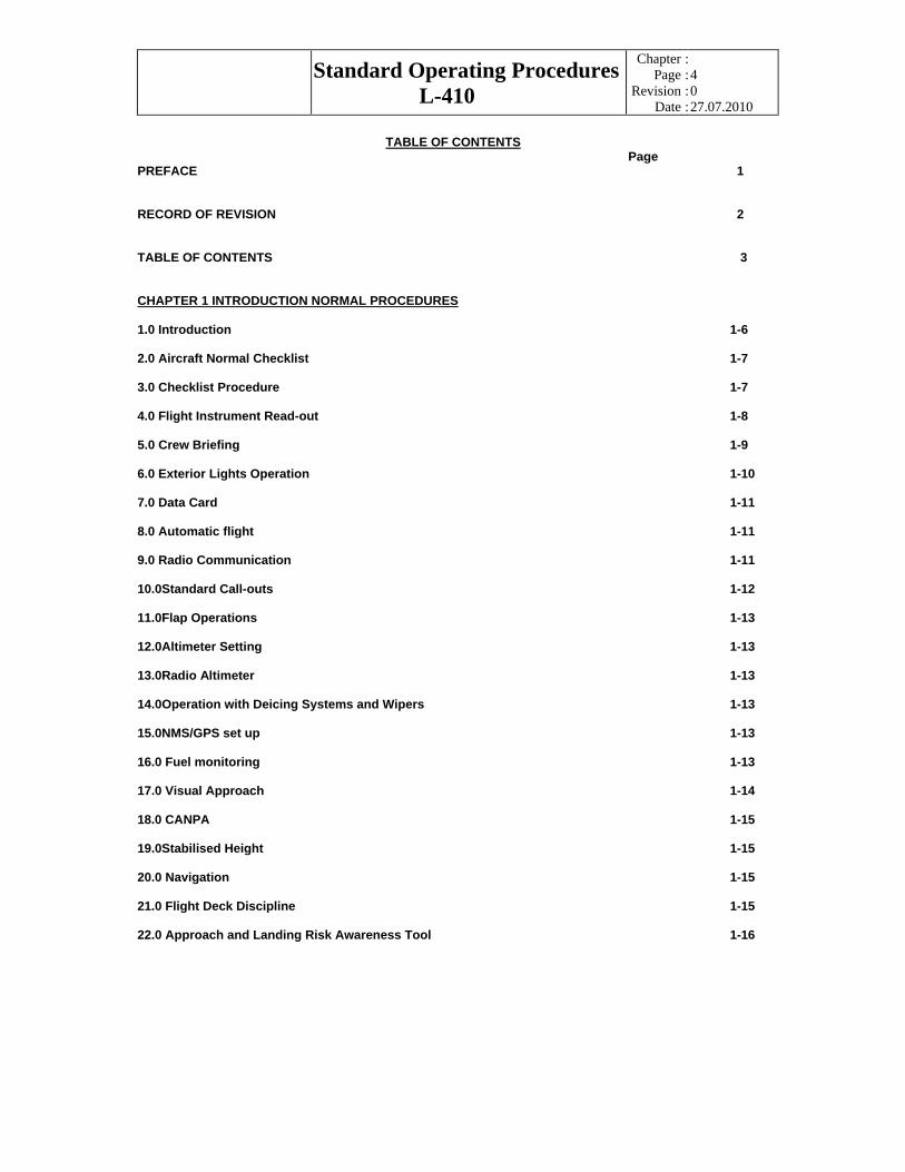
TABLE OF CONTENTS
Page PREFACE 1
RECORD OF REVISION 2
TABLE OF CONTENTS 3
CHAPTER 1 INTRODUCTION NORMAL PROCEDURES
1.0 Introduction 1-6
2.0 Aircraft Normal Checklist 1-7
3.0 Checklist Procedure 1-7
4.0 Flight Instrument Read-out 1-8
5.0 Crew Briefing 1-9
6.0 Exterior Lights Operation 1-10
7.0 Data Card 1-11
8.0 Automatic flight 1-11
9.0 Radio Communication 1-11
10.0Standard Call-outs 1-12
11.0Flap Operations 1-13
12.0Altimeter Setting 1-13
13.0Radio Altimeter 1-13
14.0Operation with Deicing Systems and Wipers 1-13
15.0NMS/GPS set up 1-13
16.0 Fuel monitoring 1-13
17.0 Visual Approach 1-14
18.0 CANPA 1-15
19.0Stabilised Height 1-15
20.0 Navigation 1-15
21.0 Flight Deck Discipline 1-15
22.0 Approach and Landing Risk Awareness Tool 1-16
Standard Operating Procedures
L-410
Chapter
Page
Revision
Date
::::
5 0 27.07.2010
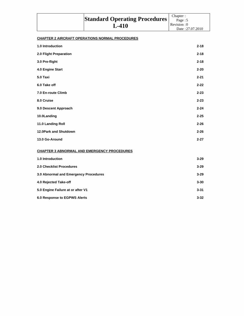
CHAPTER 2 AIRCRAFT OPERATIONS NORMAL PROCEDURES
1.0 Introduction 2-18
2.0 Flight Preparation 2-18
3.0 Pre-flight 2-18
4.0 Engine Start 2-20
5.0 Taxi 2-21
6.0 Take off 2-22
7.0 En-route Climb 2-23
8.0 Cruise 2-23
9.0 Descent Approach 2-24
10.0Landing 2-25
11.0 Landing Roll 2-26
12.0Park and Shutdown 2-26
13.0 Go-Around 2-27
CHAPTER 3 ABNORMAL AND EMERGENCY PROCEDURES
1.0 Introduction 3-29
2.0 Checklist Procedures 3-29
3.0 Abnormal and Emergency Procedures 3-29
4.0 Rejected Take-off 3-30
5.0 Engine Failure at or after V1 3-31
6.0 Response to EGPWS Alerts 3-32

Standard Operating Procedures
L-410
Chapter
Page
Revision
Date
::::
6 0 27.07.2010
CHAPTER 1
INTRODUCTION
(Normal Procedures)
Standard Operating Procedures
L-410
Chapter
Page
Revision
Date
::::
7 0 27.07.2010
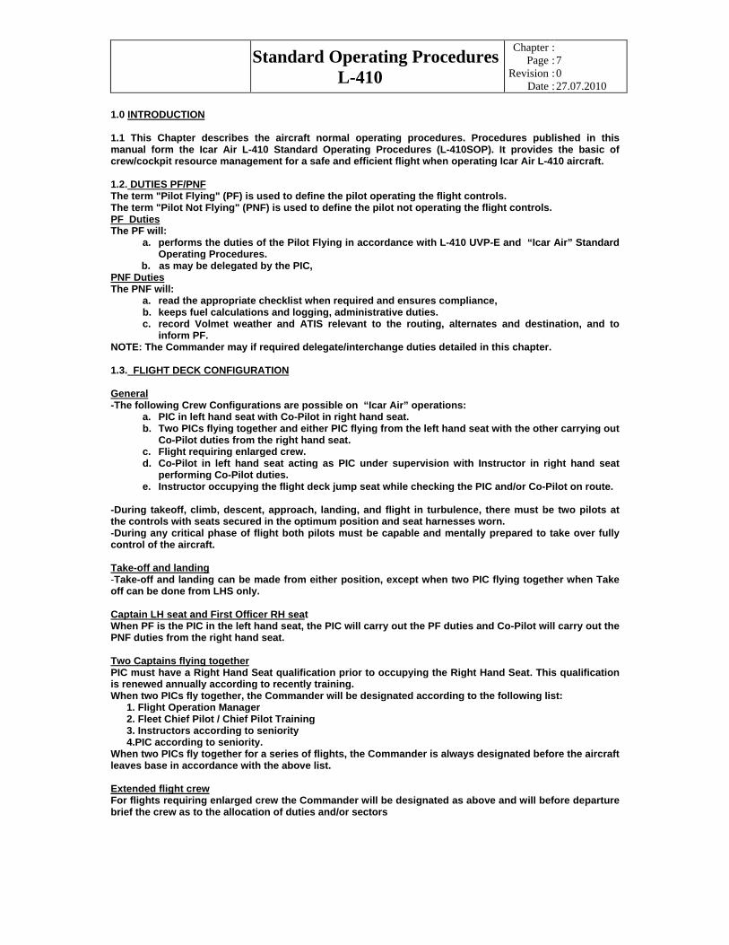
1.0 INTRODUCTION
1.1 This Chapter describes the aircraft normal operating procedures. Procedures published in this manual form the Icar Air L-410 Standard Operating Procedures (L-410SOP). It provides the basic of crew/cockpit resource management for a safe and efficient flight when operating Icar Air L-410 aircraft.
1.2. DUTIES PF/PNF
The term "Pilot Flying" (PF) is used to define the pilot operating the flight controls. The term "Pilot Not Flying" (PNF) is used to define the pilot not operating the flight controls. PF Duties
The PF will: a. performs the duties of the Pilot Flying in accordance with L-410 UVP-E and “Icar Air” Standard
Operating Procedures. b. as may be delegated by the PIC, PNF Duties
The PNF will: a. read the appropriate checklist when required and ensures compliance, b. keeps fuel calculations and logging, administrative duties. c. record Volmet weather and ATIS relevant to the routing, alternates and destination, and to
inform PF. NOTE: The Commander may if required delegate/interchange duties detailed in this chapter.
1.3. FLIGHT DECK CONFIGURATION
General
-The following Crew Configurations are possible on “Icar Air” operations: a. PIC in left hand seat with Co-Pilot in right hand seat. b. Two PICs flying together and either PIC flying from the left hand seat with the other carrying out
Co-Pilot duties from the right hand seat. c. Flight requiring enlarged crew. d. Co-Pilot in left hand seat acting as PIC under supervision with Instructor in right hand seat
performing Co-Pilot duties. e. Instructor occupying the flight deck jump seat while checking the PIC and/or Co-Pilot on route.
-During takeoff, climb, descent, approach, landing, and flight in turbulence, there must be two pilots at the controls with seats secured in the optimum position and seat harnesses worn. -During any critical phase of flight both pilots must be capable and mentally prepared to take over fully control of the aircraft.
Take-off and landing
-Take-off and landing can be made from either position, except when two PIC flying together when Take off can be done from LHS only.
Captain LH seat and First Officer RH seat When PF is the PIC in the left hand seat, the PIC will carry out the PF duties and Co-Pilot will carry out the PNF duties from the right hand seat.
Two Captains flying together
PIC must have a Right Hand Seat qualification prior to occupying the Right Hand Seat. This qualification is renewed annually according to recently training. When two PICs fly together, the Commander will be designated according to the following list:
1. Flight Operation Manager 2. Fleet Chief Pilot / Chief Pilot Training 3. Instructors according to seniority 4.PIC according to seniority.
When two PICs fly together for a series of flights, the Commander is always designated before the aircraft leaves base in accordance with the above list.
Extended flight crew
For flights requiring enlarged crew the Commander will be designated as above and will before departure brief the crew as to the allocation of duties and/or sectors

Standard Operating Procedures
L-410
Chapter
Page
Revision
Date
::::
8 0 27.07.2010
Pilots under training/supervision
When a PIC is being checked or supervised in his duties, or a First Officer is being trained or supervised as a PIC, the Commander (Instructor) will occupy the right-hand seat and carry out the duties of the Co-Pilot. If a First Officer is PF from the left hand seat as PIC under supervision, he will carry out the duties of PIC. The Commander in the right hand seat will carry out the Co-Pilot duties.
Crew line check
If an Instructor or Check Pilot is occupying the Flight Deck jump seat for the purpose of carrying out Route Checks of either or both pilots, then he will assign PF and PNF duties to either pilot. When a PIC and Co-Pilot are being checked together in their normal operating categories, the Instructor will occupy the jump seat. During this time the designated PIC shall be the Commander and will be responsible for all decisions taken during the flight. During this time, the Instructor acts as an advisor and he may offer advice of a technical or operational nature. However, if the situation warrants the Instructor may at any time take overall responsibility and assume Command. Commander will sign Aircraft documents.
Supernumerary flight crew
Supernumerary crewmember will occupy the jump seat. For take off and landing and flight in turbulence, a full seat harness will be worn by the supernumerary crewmember
2.0 AIRCRAFT NORMAL CHECKLIST
2.1The Icar Air L-410 Normal Checklist will be used in conjunction with the amplified check list. This checklist shall be used to operate company’s L-410 aircraft through all phases of a normal flight.
2.2 The appropriate normal procedures are performed first by recall (memory) and followed by reference to the checklist to verify that all items have been accomplished. The check or test procedures for each item are in accordance with the amplified checklist.
2.3 Any light that does not illuminate during a system test will be checked by press-to-test.
2.4 Crew members designated to challenge and respond to the checklist are responsible to ensure each checklist item is correctly set and loudly responded to before proceeding to the next item.
2.5 Silent checklist, such as the After Take-off and After Landing checklists, will not be challenged and responded. When such checklist is called for, the PNF will verify each checklist item silently and announce “XXXchecklist completed”. If any item is not appropriate with reference to checklist, the PNF will challenge PF and ensure it is set correctly in accordance with the normal checklist.
2.6” No Smoking “sign will be switched on at all times.
2.7 Interrupting and Resuming Normal Checklist
. The deliberate holding of checklist at any item is not encouraged. Hence, timely initiation and completion of reading the normal checklist s is the most effective method of preventing any omission of actions or preventing any inappropriate actions. Should however, the flow of the normal checklist is interrupted for any reason (ATC, distractions in the cockpit, system malfunction, etc), the crew reading checklist should call”Holding checklist at….(item)”.
Once ready to continue with the checklist, the crew should say “Resuming checklist at…(item)” . When resuming the normal checklist after an interruption, the last completed item should be repeated. If the interruption is more then 1 minute or whenever is doubt, then the whole checklist is to be repeated from the start.
3.0 CHECKLIST PROCEDURES
3.1 Cues are provided to indicate each phase of the checklists. These cues are non-verbal indicators used to communicate among crewmembers that the appropriate checklist sequence should be followed. The cues will reduce unnecessary cockpit chatter and also serve as indicators, should the checklist be inadvertently bypassed or forgotten. 3.2 Silent checklist will be responded in lower tone by PNF and should be heard by PF. 3.3 Checklist challenge, response and cues are summarised bellow:

Standard Operating Procedures
L-410
Chapter
Page
Revision
Date
::::
9 0 27.07.2010
CHECKLIST CALLED
BY CHALLENGED BY
RESPONED
CUES
PRELIMINARY COCKPIT PREPARATION
LHS pilot RHS pilot Aloud Before instrument read-out
PRE-START LHS pilot RHS pilot Aloud After instrument read-out AFTER START LHS pilot RHS pilot Aloud After last engine has been started and
stabilised ,all devices disconnected from aircraft
BEFORE TAXI LHS pilot RHS pilot Aloud After obtaining taxi clearance BEFORE LINE UP
LHS pilot RHS pilot Aloud Approaching holding point
BEFORETAKE OFF
LHS pilot RHS pilot Aloud After line up
AFTER TAKE OFF
PF PNF Silent After PNF called out “Flaps up, climb power set”
CRUISE PF PNF Silent Upon reaching assigned FL(altitude) DESCENT PF PNF Aloud Established with speed and rate in
descent APPROACH PF PNF Aloud After passing transition level BEFORE LANDING
PF PNF Aloud After extension flaps for landing
AFTER LANDING
LHS pilot RHS pilot Silent LHS pilot selected pedals on manual
SHUTDOWN LHS pilot RHS pilot Aloud After engines shutdown and propellers stopped rotating
4.0 FLIGHT INSTUMENTS READ-OUT
4.1 Flight instruments read-out is part of the Pre-start Checklist scan flow. Prior to commencement of “Prestart checklist”, the LHS pilot will check-in crewmembers and initiate the instrument readout according to the items as listed in the table below. 4.2 The LHS pilot will read out the appropriate flight instrument indications to ensure that they are functional and properly set for flight. The RHS pilot will follow through the readout and only highlight any discrepancy or out-of-tolerance comparison. 4.3 Instruments shown below are arranged in a scan flow pattern and shall be read out in a standard and orderly manner so that the FO (RHS pilot) can easily predict the flow pattern:
INSTRUMENT READOUT
INSTRUMENT READ-OUT ASI ASI indicates zero
Take off flaps 18 , speeds are V1….,Vr….V2….V2+10…Flaps up….kts. ADI & Standby Horizon
ADI off, ball in the centre SBY horizon off
Altimeter Altimeter QNH set…..mb indicating ….ft.Airport elevation …ft (within altimeter tolerance)
Radio Altimeter RA tested and indicating zero. Minimum safety height 400ft set. No flags RMI,HSI and STBY compass
RMI heading…./HIS heading…./STBY heading…. HIS Course cursor set…/Heading cursor set…/RMI selector No.1 on VOR/ADF…No.2 on VOR/ADF…
IVSI IVSI reading zero.TCAS OFF(on STBY) Clock and Time Time checked with GPS….UTC. Clock re-wounded and set Engine instruments Checked, Indicating zero, fuel quantity….. kg in main tanks and …..kg in wing tip
tanks GPS GPS route…… set and checked

Standard Operating Procedures
L-410
Chapter
Page
Revision
Date
::::
10 0 27.07.2010
5.0 CREW BRIEFING
5.1 Appropriate crew briefing will be given in conjunction with the various critical phases of flight to ensure mutual understanding and effective cooperation among flight crewmembers and air traffic control.
5.2 Care should be taken to conduct a through briefing regardless of how familiar the destination airport and the approach may be; or how often the crewmembers have flown together.
5.3 An interactive briefing style-e.g. confirming the agreement and understanding of the other crewmember after each phase of the briefing –will provide a more effective briefing than an uninterrupted recitation by the final query,” Any questions?”
a. An interactive briefing fulfils two important purposes: (1) To provide the PF and the PNF with an opportunity to correct each other (2) To share a common image of the procedure.
B.The briefing should be structured (i.e. follow the logical sequence of events) and concise.
C.Routine and formal repetition of the same information on each flight may be counterproductive; adapting and expanding the briefing by highlighting the special aspects of departure /approach or the actual weather conditions will result in more effective briefing.
d. Anything that may affect normal operations (e.g. system failures or weather conditions) should be carefully evaluated and discussed.
e. For approach briefings, the primary elements of Go-Around procedures and task sharing under normal or abnormal conditions should be discussed
5.4. It shall include the relevant silent points as listed below in the crew briefing format . For subsequent sectors, “take-off emergency brief below V1” will be mentioned as “standard” without repeating the same brief.
CREW BRIEFING FORMAT
BRIEF GIVEN BY
SAILENT POINTS
Take-off Emergency Brief(before V1)
Captain -LHS or RHS take off. -Normal/Rolling/Static take –off. -Any crew who notices any abnormality below V1 will call out the Malfunction. If I decide to reject the take-off, I will call out”REJECT” Followed by the reject procedure: *Close both power levers *Apply full brakes * Reverse power as required -Any abnormality below V1 take-off will be rejected -At V1 or above , take off will continue
Take-off Emergency Brief(after V1)
Pilot- flying
-Abnormality after V1 will continue the take-off -No action below 400ft AGL except to rise the LG and at 200 ft “Auto Bank Control” off if necessary - Level-off accelerating altitude is……..ft -Special procedure…….(or no Special procedure) -Initial decision will be…….(SID,heading,ATC etc.)
Take-off ATC Brief Pilot- Flying
-Air traffic clearance reviewed -Altitude management system set at ……ft -Transporder set……. -MSA ……ft/sector climb gradient/DME step
Departure Brief Pilot- Flying
-Review departure altitude , heading , radial intercept or direction of turn -Straight climb or close turn. -Noise and speed procedures . -Specific or non-standard points. -Wind velocity&expected weather conditions on departure. -Specific consideration for any known system malfunction

Standard Operating Procedures
L-410
Chapter
Page
Revision
Date
::::
11 0 27.07.2010
-Take-off clearance
Descent-Approach Brief
Pilot- flying
-Weather at destination -TOD point -Preferred type of approach(visual or instrument) -Instrument approach brief(expected instrument approach including MAP) -Navigation aids to be set up for approach and missed approach -Specific consideration for any known system malfunction -Expected runway exit after landing -Landing flaps and speed -Weather at diversion and minimum fuel for diversion. Holding time available -GA procedure to be reviewed at least on the first sector if on a multi sector task or whenever the situation warrants
Post-flight Debrief Captain -Flight safety -Operations -CRM and SOP
6.0 EXTERIOR LIGHTS OPERATION
6.1Exterior lights are designed to illuminate a specific direction of area and as such should be operated accordingly. Operations of exterior lights are summarised below:
STANDARD OPERATION OF EXTERIOR LIGHTS
PHASES OF FLIGHT (in chronological order)
DAY LIGHTS ON/OFF
NIGHT LIGHTS ON/OFF
PRE-FLIGHT -NAV Lights ON -NAV Lights ON PUSHBACK& ENGINE START
-Beacon ON -Beacon ON
TAXI OUT -Taxi lights ON Taxi light ON
OBTAINED TAKE-OFF CLEARENCE
-Landing lights
ON -Landing lights
ON
AFTER TAKE-OFF -Landing lights -Taxi lights
OFF ON
-Landing lights -Taxi lights
OFF ON
AT TOP OF CLIMB -Taxi lights OFF -Taxi lights OFF
CRUISE Static detector Inspection light
As required
AT TOP OF DESCENT -Taxi lights ON -Taxi lights ON OBTAINED LANDING CLEARANCE OR 1000ft
-Landing lights
ON -Landing lights ON
TAXI CLEAR OF RUNWAY
-Landing lights -Taxi lights
OFF ON
-Landing lights -Taxi lights
OFF ON
TAXI IN -Taxi lights ON -Taxi lights ON PARKING -Taxi lights OFF -Taxi lights OFF ENGINES SHUTDOWN -Beacon OFF -Beacon OFF TRANSIT/TERMINATING FLIGHT
-NAV Lights OFF -NAV Lights OFF
6.2 On ground, the captain will operate with all exterior lights. In flight, the PNF will operate all exterior lights.

Standard Operating Procedures
L-410
Chapter
Page
Revision
Date
::::
12 0 27.07.2010
7.0 DATA CARD
7.1 Data Cards are part of the Operational Flight plan and should be completed by FO prior to instrument read out for take-off, and by PNF, before PF briefing, for descent approach.
7.2 All completed data cards must be returned to the Flight Operations Control. Captain is responsible to ensure accuracy of the data entered in data cards.
8.0 AUTOMATIC FLIGHT
8.1The optimum and proper use of automated flight system reduces workload and increases the time and resources available for the flight crew for responding to any unanticipated change or abnormal/emergency situation.
8.2 During normal line operations , the autopilot system should ideally be engaged thought the flight , as soon as practicable after take-off (recommended after aircraft clean up or 1500 ft AGL whichever is later) up to the point of approach(not bellow 200ft AGL) especially in marginal weather or when operating in unfamiliar airports.
8.3 The PF, however, always retains the authority and the capability to use the most appropriate guidance and level of automation for any task. When conducting automated instrument approaches, PF is expected to have his hands lightly on controls in readiness to take over control manually if the need arises. If the aircraft doesn’t follow the desired horizontal or vertical flight path and time doesn’t permit analyzing and solving the anomaly, revert without delay to hand-flying (with or without FD) for direct control of the aircraft trajectory. If the autopilot trips during ILS LOC/GS intercept, hand fly on the FD commands and stabilise on the ILS first before attempting to reengage the autopilot. When hand flying the FD should be followed, otherwise the FD commands bars should be cleared from ADI display.
8.4 Engagement of any automatic system to the autopilot requires the PF to call out the engagement and crosschecked by PNF(systems such as NMS NAV mode,AMS armed ,ILS APP , Heading select,IAS hold etc.)
8.5 The illumination of the Approach Progress Display armed lights during engagement will be called out by the PF (……..Armed) and responded by PNF(Checked), while the illumination of the APD green captured lights will be called out by the PNF(………..Captured) and responded by the PF ( Checked)
8.6 Altitude Management System (altitude alert) can be selected only by LHS pilot. He will call out selected altitude and must ensure that the appropriate QNH/QNE is selected in LHS altimeter Upon verification of selected altitude and rate of climb/descent the LHS pilot shall arm selected rate and altitude and call out “………rate of climb/descent and ………ft altitude Set and Armed. The RHS pilot will crosscheck and respond “Checked”. Upon reaching selected altitude when “ alt. captured” appears in the window the PNF should call out “Altitude Captured “ and PF respond “Checked” . Upon levelling off the PNF should call out” Altitude hold” and PF respond “Checked”.
8.7 The autopilot “HDG select” as means of lateral/directional control is encouraged to be used under the following circumstances:
a. For all SIDs; b. Under positive radar vectored environment; c. For all instrument approaches; d. For weather avoidance in flight that requires large and frequent changes e. Below 10 000ft
Note: When RHS is PF he should call out the heading commands for LHS pilot to select. Before engaging the HDG select ensure that HDG bug on LHS instrument is correctly set on the required heading
9.0 RADIO COMMUNICATION
9.1 Our aircraft is installed with two VHF radios and one HF radio.
9.2 Standard setup of VHF radios is as follows:
VHF1- ATC(transferable) VHF2-ATIS,121.5,ops.control
Standard Operating Procedures
L-410
Chapter
Page
Revision
Date
::::
13 0 27.07.2010
9.3 The FO is responsible for monitoring ATIS and communication with the Flt.Ops. on ground while in the air selection of radios, monitoring ATIS and communication is responsibility of PNF.
9.4 Usage of headset is mandatory during entire flight and it’s only mean of radio communication.
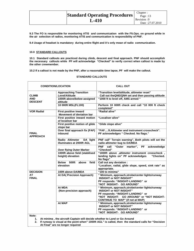
10.0 STANDARD CALLOUTS
10.1 Standard callouts are practiced during climb, descent and final approach. PNF should accomplish the necessary callouts while PF will acknowledge “Checked” to verify correct when callout is made by the other crewmember.
10.2 If a callout is not made by the PNF, after a reasonable time lapse, PF will make the callout.
STANDARD CALLOUTS
CONDITION/LOCATION CALL OUT
Approaching Transition Level/Altitude
“Transition level/altitude, altimeter reset” Call out theQNE/QNH set and then passing altitude
1000ft above/below assigned altitude
“1000 ft to level off, AMS armed “
CLIMB AND DESCENT
10 000ft MSL(FL100) Perform 10 000ft check and call “10 000 ft check completed”
VOR Radial First positive inward Movement of deviation bar
“Radial alive”
First positive inward motion of localiser bar
“Localiser alive”
First positive motion of glide slope bar
“Glide slope alive”
Over final approach fix (FAF) inbound
“FAF….ft.Altimeter and instrument crosscheck”. PF acknowledges “ Checked. No flags.”
Radio Altimeter DA light illuminates at 2000ft AGL
PNF call” Terrain warning”, Both pilots will set the radio altimeter bug to DA/MDA
Over flying Outer Marker PNF call “Outer marker”, PF acknowledge “Checked”
1000ft above field (stabilised height) elevation
“1000ft above ,altimeter instrument crosscheck , landing lights on” PF acknowledges ”Checked. No flags”
FINAL APPROACH
Below 500ft above field elevation
Call out any deviation : “Localiser, radial, glide slope, speed, sink rate” as appropriate.
100ft above DA/MDA “100 to minima” At DA( Precision Approach) “ Minimum, approach,strobe/center lights/runway
INSIGHT or NOT INSIGHT” PF responds: “INSIGHT-LANDING” or “NOT INSIGHT- GO AROUND”
At MDA (Non-precision approach)
“ Minimum, approach,strobe/center lights/runway INSIGHT or NOT INSIGHT” PF responds: “INSIGHT-LANDING” or “NOT INSIGHT- GO AROUND” or “NOT INSIGHT-CONTINUE TO MAP” (if not at MAP)
DECISION AT FINAL
At MAP “ Minimum, approach,strobe/center lights/runway INSIGHT or NOT INSIGHT” PF responds: “INSIGHT-LANDING” or “NOT INSIGHT- GO AROUND”
Note: 1. At minima , the aircraft Captain will decide whether to Land or Go Around 2. If runway is visual at the point when” 1000ft AGL” is called, then the standard calls for “Decision
At Final” are no longer required

Standard Operating Procedures
L-410
Chapter
Page
Revision
Date
::::
14 0 27.07.2010
11.0 FLAPS OPERATIONS
11.1 Refer to OM on flaps retraction-extension procedures and technique.
11.2 The PF will call for flaps selection (flaps up,18, 42 etc.). The PNF will check flaps speed limit, call out flaps setting before selecting the flaps. With the flaps indicator showing and illumination of selected flaps position the PNF will call out “Flaps….green light” a PF will response “Checked”.
12.0 ALTIMETER SETTING
12.1 Altimeters should be reset after passing the Transition Level or Altitude. PNF will call for altimeter reset. Standard call out will be “Transition, altimeter reset” and then set the QNE or QNH as appropriate. Both pilots will reset the altimeters and PNF will call out altitude passing for altimeter accuracy check. ( e.g.” Passing FL 100 now” and PF will response” + or – 50 ft “depends of deviation)
13.0 RADIO ALTIMETER
13.1 During pre-flight check, the radio altimeter will be set at below zero (indicator out of view and DH light extinguished) During the 10 000 ft check on climb, it will be set at 2000 ft. While on the descent and when the DH light illuminates, the PNF will call out “Terrain warning” and both pilots will reset the radio altimeter bug to DH/MDH unless runway is visual.
13.2 The radio altimeter is NOT to be used as the primary DA/MDA reference for instrument approaches but as a back-up to the pressure altimeter.
13.3 Use of radio altimeter DH light to monitor supplementary system operations ( e.g. wing tip tanks fuel transfer, de-icing of propellers are being used etc.) is encouraged.
14.0 OPERATION OF DEICING SYSTEMS AND WIPERS
14.1 The F/O is responsible to operate all de-icing systems whenever the situation warrants with the knowledge and approval of Captain or when requested by Captain. The F/O should monitor operational limitations of de-icing systems when any of them is in use, and inform Captain whenever the switches are selected on/off or being transferred. The Captain is responsible for the wipers operation and should inform F/.O whenever they are switched on / off.
15.0 NMS/GPS SET-UP
15.1 The NMS/GPS flight plan will be set in accordance with the published operational flight plan (SITA, Flight Star). One flight plan on the NMS/GPS is sufficient for the dispatch. Multiple flight plans may be set on the NMS/GPS provided dispatch time is not affected.
15.2 All waypoint coordinates must be checked with the published charts before inserting into the NMS/GPS as flight plan. The F/O will set up the flight plan during the pre-flight and the flight plan will be checked by the Captain. If the Captain chooses to set the NMS/GPS as non-standard practice, the F/O must crosscheck the flight plan.
16.0 FUEL MONITORING
16.1 Fuel monitoring is of high importance and it is mandatory during entire flight. Fuel remaining will be checked over every identifiable waypoint or navigational aid or at least once every 30 minute period. The F/O will provide fuel remaining figure, compared to the flight plan, to the Captain upon request.

Standard Operating Procedures
L-410
Chapter
Page
Revision
Date
::::
15 0 27.07.2010
16.2 Holding Reserve/Final reserve/Emergency Fuel Reserve.
When the total fuel remaining reads 200 kg
ATC should be informed that you are operating on Holding Reserve i.e. remaining of 30 minutes. PAN call should be declared when the total fuel remaining has reached 100 kg which will provide sufficient fuel for approach to Minima, missed approach followed by a visual circuit to land . Upon declaring a PAN call, you are expected to land the aircraft, but should a Missed Approach or a GO-AROUND becomes inventible, a MAYDAY call should then be declared when the total fuel remaining in tanks is less than 100 kg.
17.0 VISUAL APPROACH
17.1 Visual approaches are considered cost saving measures for the company and are encouraged whenever the following conditions are met and discussed by crew prior to deciding for a visual approach:
a. Prevailing meteorogical conditions and ATC permitting;
- Reported weather at the airport must ceiling at or above 5000ft AGL and visibility 10km or greater; - The approach must be authorised and under the control of appropriate air traffic control facility; - The crew flying must, at all times, have either the terrain, airport or the preceding aircraft in sight; - Crew must be aware of all weather factors such as strong wind(including tailwind0, turbulence,
low clouds or impending rain;
b. Other pertinent variables/considerations/requirements:
- Crew need to be familiar and have ample experience with airport and airport environment including surrounding terrain, specific airport and runway hazards, runway visual aids such as availability of approach light system,VASI or PAPI;
- To enhance situational awareness , set navigational aids for the instrument approach associated with the landing runway( use information from the navigational aids intelligently for monitoring of profile and also in the case of loss of the visual references);
- Optimising of automation with timely reversion to hand flying; - Adhering to defined PF/PNF task-sharing (PF flies and look outside while PNF monitors head-
down references i.e. instrument references); - The primary elements of the visual approach, associated instrument approach and appropriate
missed approach procedure must be reviewed prior to commencing the approach
17.2 Guidance when conducting visual approaches;
a. The management of the aircraft energy during descent must be proficiently executed in order to achieve the objective of cost saving. Ideally, without compromising safety, the aircraft should be flown during descent with engine power levers set to idle up to the point where appropriate engines power should be reset ( usually after LG extension) in final preparation for landing.
b. For a “straight-in” approach (any approach within 45 degrees of the centreline); - Aim to be 3000ft AGL and 150-160 knots 10 track miles to touch down; - At this point, start reducing speed in preparation for LG and flaps extension; - At 7 miles to touch down lower the landing gear (speed 135 knots) - At 6 miles extend flaps 18 and reduce speed to 110knots; - At 4 track miles extend landing flaps 42 (if appropriate) and begin reducing speed to the target Final approach speed; - Aircraft must be on stabilised approach by 500ft AGL. c. For the purpose of aircraft training within circuits, the designated circuit altitude is 1500 ft AGL.It should be highlighted that when conducting visual approaches, visual references should always be complemented with references from instruments and navigational aids.
17.3 Visual Approach at Night This is not encouraged due to the following constraints:
a. Fewer visual references are useable and visual illusions and spatial disorientation occurs more frequently;
b. Visual illusions (such as the black-hole effect) affect the flight crew’s vertical situational awareness and horizontal situational awareness, particularly on the base leg and when turning final;
Standard Operating Procedures
L-410
Chapter
Page
Revision
Date
::::
16 0 27.07.2010
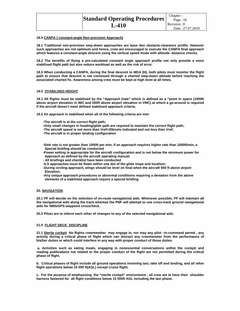
18.0 CANPA ( constant-angle Non-precision Approach)
18.1 Traditional non-precision step-down approaches are base don obstacle-clearance profile. However such approaches are not optimum and hence, crew are encouraged to execute the CANPA final approach which features a constant-angle descent using the vertical speed mode with altitude- distance checks.
18.2 The benefits of flying a pre-calculated constant angle approach profile not only provide a more stabilised flight path but also reduce workload as well as the risk of error.
18.3 When conducting a CANPA, during the final descent to MDA (H), both pilots must monitor the flight path to ensure that descent is not continued through a charted step-down altitude before reaching the associated charted fix. Awareness among crew must be kept at high level at all times.
19.0 STABILISED HEIGHT
19.1 All flights must be stabilised by the “Approach Gate” which is defined as a “point in space (1000ft above airport elevation in IMC and 500ft above airport elevation in VMC) at which a go-around is required if the aircraft doesn’t meet defined stabilised approach criteria.
19.2 An approach is stabilised when all of the following criteria are met:
-The aircraft is at the correct flight path; -Only small changes in heading/glide path are required to maintain the correct flight path; -The aircraft speed is not more than Vref+20knots indicated and not less than Vref; -The aircraft is in proper landing configuration
-Sink rate is not greater than 1000ft per min; if an approach requires higher rate than 1000ft/min, a Special briefing should be conducted -Power setting is appropriate for the aircraft configuration and is not below the minimum power for Approach as defined by the aircraft operating manual;
- All briefings and checklist have been conducted -ILS approaches must be flown within one dot of the glide slope and localiser; -During circling approach, wings should be level on final when the aircraft 500 ft above airport Elevation; -Any unique approach procedures or abnormal conditions requiring a deviation from the above elements of a stabilised approach require a special briefing.
20. NAVIGATION
20.1 PF will decide on the selection of en-route navigational aids. Whenever possible, PF will maintain all the navigational aids along the track whereas the PNF will attempt to use cross-track ground navigational aids for NMS/GPS waypoint crosscheck.
20.2 Pilots are to inform each other of changes to any of the selected navigational aids.
21.0 FLIGHT DECK DISCIPLINE
21.1 Sterile cockpit
No flights crewmember may engage in, nor may any pilot –in-command permit , any activity during a critical phase of flight which can distract any crewmember from the performance of his/her duties or which could interfere in any way with proper conduct of those duties.
a. Activities such as eating meals, engaging in nonessential conversations within the cockpit and reading publications not related to the proper conduct of the flight are not permitted during the critical phase of flight.
b. Critical phases of flight include all ground operations involving taxi, take off and landing, and all other flight operations below 10 000 ft(AGL) except cruise flight.
c. For the purpose of emphasizing the “sterile cockpit” environment , all crew are to have their shoulder harness fastened for all flight conditions below 10 000ft AGL including the taxi phase.

Standard Operating Procedures
L-410
Chapter
Page
Revision
Date
::::
17 0 27.07.2010
21.2 Transfers of Control At any one time, a pilot must be in control of the aircraft of the aircraft and in order to avoid any confusion as to who is having the controls, a proper handing over and taking over of controls must be conducted.
a. The aircraft Captain has the authority to take over control from his/her co-pilot whenever he/she feels that the situation warrants him/her to do so. The aircraft Captain must clearly state his/her intention by saying out positively “I have Control” and the co-pilot must acknowledge “You have Control”. The Captain then ends the procedure by saying “My Control”.
b. On the other hand, whenever a pilot wishes to hand over control to the other pilot, he/she must state his/her intention by saying “You have Control” and the other pilot must acknowledge and respond by saying” My Control”
c. Monitored Approach
During poor visibility approaches when the aircraft Captain is expected to make the landing, it is encouraged that allows the First Officer to carry out the instrument approach while he/she closely monitors the conduct of the approach. Besides making all the standard call outs, the Captain shall also be looking for visual cues (before or at minima) for the landing. The Captain shall take over control of the aircraft positively at or before the minima once he/she has the necessary visual cues required to to continue the approach for landing while the First Officer shall now revert to PNF role. The task sharing role of each individual pilot must be properly briefed by the Captain prior to conducting such an approach.
d. After landing
Whenever a RHS pilot makes the landing, transfer of control of the aircraft to the LHS pilot during the landing roll shall be made once the aircraft has attained a normal taxi speed. The position of the reverse thrust levers when transferring controls shall be in beta range at idle.
21.3 Leaving the Flight Deck In-flight No crew is allowed to leave cockpit during any critical (Refer to 21.1b for definition), climb and descent phases of flight. During non-critical phase of flight, only one crewmember at a time is allowed to leave his/her station. He/she is to advise the other crewmember of his/her intention as well as brief of any outstanding or impending matters that needed to be monitored or attended to. Upon coming back to his/her station, he/she should announce that he/she is back and ready to be updated on any change(s) of the flight status while he/she was away. It is the duty of the other crewmember(pilot) to inform him / her about any change(s) if such one happened .If there wasn’t any change or call the duty of pilot who was in the station( seat) is to say “NO changes, no calls” and arriving crewmember must confirm by “Roger”.
22.0 Approach and Landing Risk Awareness Tool Checklist
22.1 The Approach and Landing Risk Awareness Tool (laminated checklist available in the aircraft) is to be referred to all crew whenever a planned or unplanned diversion is being contemplated or whenever crew is being tasked to fly to a new destination for the first time. This is to create the necessary awareness among all crew off all the possible approach and landing risks that they may be exposed to.
22.2 The Captain of the aircraft is responsible in deciding on the most suitable time to initiate the brief.

Standard Operating Procedures
L-410
Chapter
Page
Revision
Date
::::
18 0 27.07.2010
CHAPTER 2
AIRCRAFT OPERATIONS (Normal Operations)
AIRCRAFT OPERATIONS
1.0 INTRODUCTION
1.1 Normal procedures contained in this SOP are procedures slightly modified from “LET” Normal Procedures. It is published to suit” Icar Air” operating environment. Technically and conceptually, this SOP adheres to the “LET” Normal Procedures.
Standard Operating Procedures
L-410
Chapter
Page
Revision
Date
::::
19 0 27.07.2010
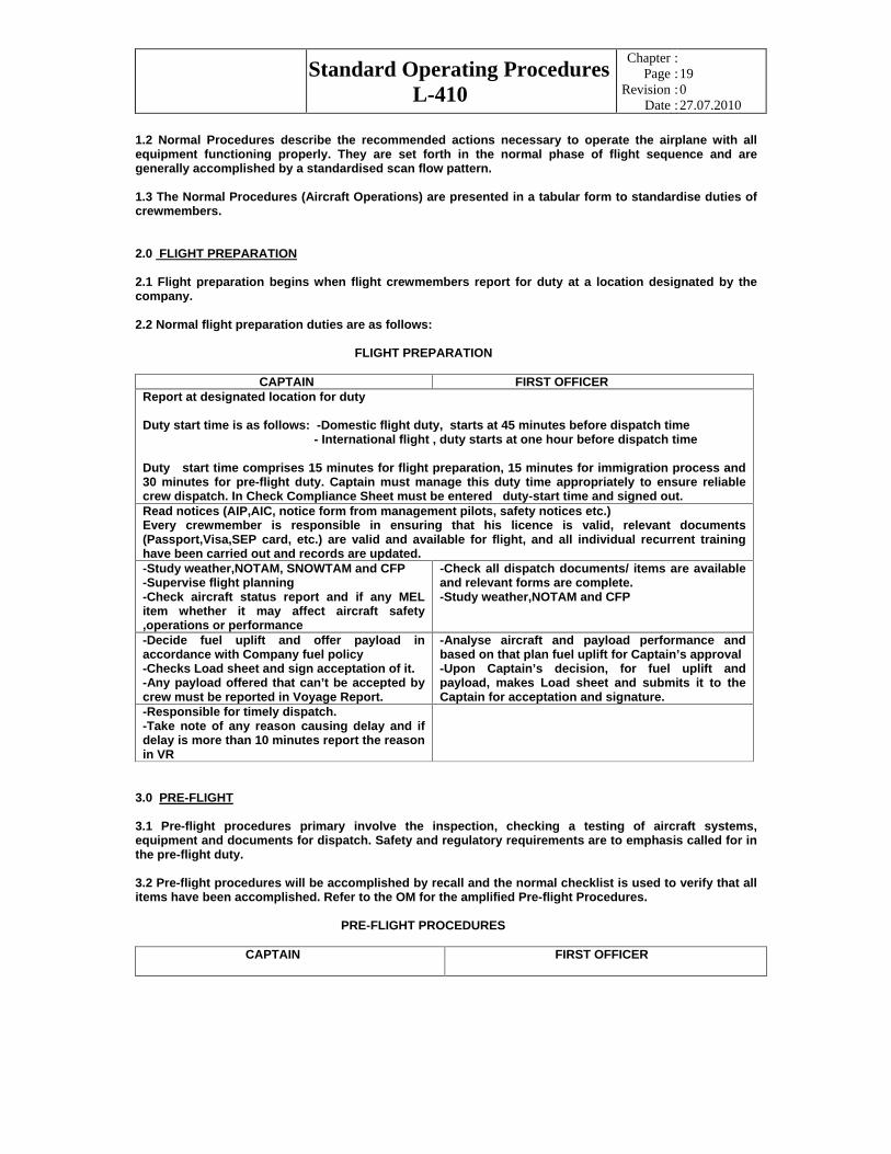
1.2 Normal Procedures describe the recommended actions necessary to operate the airplane with all equipment functioning properly. They are set forth in the normal phase of flight sequence and are generally accomplished by a standardised scan flow pattern.
1.3 The Normal Procedures (Aircraft Operations) are presented in a tabular form to standardise duties of crewmembers.
2.0 FLIGHT PREPARATION
2.1 Flight preparation begins when flight crewmembers report for duty at a location designated by the company.
2.2 Normal flight preparation duties are as follows:
FLIGHT PREPARATION
CAPTAIN FIRST OFFICER Report at designated location for duty
Duty start time is as follows: -Domestic flight duty, starts at 45 minutes before dispatch time - International flight , duty starts at one hour before dispatch time
Duty start time comprises 15 minutes for flight preparation, 15 minutes for immigration process and 30 minutes for pre-flight duty. Captain must manage this duty time appropriately to ensure reliable crew dispatch. In Check Compliance Sheet must be entered duty-start time and signed out. Read notices (AIP,AIC, notice form from management pilots, safety notices etc.) Every crewmember is responsible in ensuring that his licence is valid, relevant documents (Passport,Visa,SEP card, etc.) are valid and available for flight, and all individual recurrent training have been carried out and records are updated. -Study weather,NOTAM, SNOWTAM and CFP -Supervise flight planning -Check aircraft status report and if any MEL item whether it may affect aircraft safety ,operations or performance
-Check all dispatch documents/ items are available and relevant forms are complete. -Study weather,NOTAM and CFP
-Decide fuel uplift and offer payload in accordance with Company fuel policy -Checks Load sheet and sign acceptation of it. -Any payload offered that can’t be accepted by crew must be reported in Voyage Report.
-Analyse aircraft and payload performance and based on that plan fuel uplift for Captain’s approval -Upon Captain’s decision, for fuel uplift and payload, makes Load sheet and submits it to the Captain for acceptation and signature.
-Responsible for timely dispatch. -Take note of any reason causing delay and if delay is more than 10 minutes report the reason in VR
3.0 PRE-FLIGHT
3.1 Pre-flight procedures primary involve the inspection, checking a testing of aircraft systems, equipment and documents for dispatch. Safety and regulatory requirements are to emphasis called for in the pre-flight duty.
3.2 Pre-flight procedures will be accomplished by recall and the normal checklist is used to verify that all items have been accomplished. Refer to the OM for the amplified Pre-flight Procedures.
PRE-FLIGHT PROCEDURES
CAPTAIN FIRST OFFICER

Standard Operating Procedures
L-410
Chapter
Page
Revision
Date
::::
20 0 27.07.2010
-Exterior safety inspection (walk around) to look for existence of safety hazards surrounding the aircraft and to verify in the aircraft state. This includes apron activities, aircraft refuelling, loading equipment connected to the aircraft and general state of the aircraft. -Navigation lights must be on whenever aircraft is at the apron and some activities about it are on.
-Check aircraft safety equipment in accordance with the aircraft layout. -Cockpit safety inspection
-Check aircraft Technical Log -Check status of fuel, oxygen in bottles, oil and hydraulic fluid quantity. -Check aircraft cleanliness -Check all pins removed and properly stowed -Unblock flight controls and check free movement of rudder, elevator and ailerons.
-Check onboard:
*Normal Checklist *Quick Reference Handbook (Abnormal/Emergency . Procedures) *Jeppesen App.Charts master copies *Canned SITA/Flight Star Computer Flight Plan *L-410 UVP-E AFM *L-410 UVP-E System Manual *Flight Operation Policy Manual *Spare forms *Tech.Log, Fuel Log and MEL *Journey Log Book, Licenses & certificates -On signal from G/E switch on/off all exterior lights for inspection - Brief PAX on usage of safety equipment and emergency procedures
Cockpit preparation: -Obtain latest ATIS -Test and check all equipment and warnings available from his/her position including oxygen mask and intercom -Set-up obtained QNH and navigation equipment for departure according to the ATIS information -Crosscheck NMS/GPS setting -Verify take off data - Instruct F/O to close and arm all doors
Cockpit preparation: Obtain latest ATIS -Test and check all equipment and warnings available from his/her position including oxygen mask and intercom -Set obtained QNH and navigation equipment for departure according to the ATIS information -Set up NMS/GPS -Prepare take off data and gives to Captain for verification -Close doors and report to Captain” Documents on board all doors closed and armed”
-Check-in crewmembers for instrument readout -Perform instrument read-out -Perform Emergency brief for take off and expected departure brief (if he/she is PF)
Check-in for instrument readout. No response is required if instrument cross-check is correct and within tolerance and no error observed in pilot’s instrument set-up -Perform expected departure brief (if he/she is PF)
-Call for “Preliminary cockpit preparation( turnaround if through flight) checklist” -Check and response on appropriate items from checklist
-Challenge reading aloud” Preliminary cockpit preparation( turnaround if through flight) checklist” --Check and response on appropriate items from checklist -Upon finishing checklist calls “Preliminary cockpit preparation(turnaround) checklist completed”
-Instruct F/O to request air traffic and start clearances - Confirm received clearance and highlight if there is any discrepancy between expected and briefed departure and route clearances
-Request air traffic and start clearances. Provide ATC with: *Apron position and bay/stand number *Destination *Intended cruising level *Estimate time to start-up *Latest ATIS information receive-Upon receiving clearances read back appropriate items
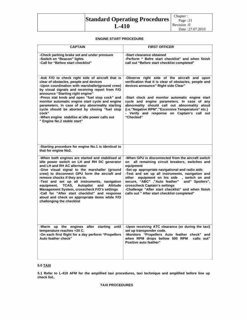
4.0 ENGINE START
4.1 Refer L-410 AFM for detailed description of engine start, after engine start procedures and amplified “Pre-start and After start “checklist.The normal engine starting sequence is No.2 (RHS engine) then No.1 (LHS) engine. Usage of GPU for engines start is encouraged whenever is possible. Push back procedure is not recommended for this type of aircraft.
Standard Operating Procedures
L-410
Chapter
Page
Revision
Date
::::
21 0 27.07.2010
ENGINE START PROCEDURE
CAPTAIN FIRST OFFICER
-Check parking brake set and under pressure -Switch on “Beacon” lights -Call for “Before start checklist”
-Start clearance obtained -Perform “ Befre start checklist” and when finish call out “Before start checklist completed”
-Ask F/O to check right side of aircraft that is clear of obstacles, people and devices -Upon coordination with marshaller(ground crew) by visual signals and receiving report from F/O announce “Starting right engine” -Press stat knob and open “fuel stop cock” and monitor automatic engine start cycle and engine parameters. In case of any abnormality starting cycle should be aborted by closing “fuel stop cock” -When engine stabilise at idle power calls out ” Engine No.2 stable start”
-Observe right side of the aircraft and upon verification that it is clear of obstacles, people and devices announce” Right side Clear”
-Start clock and monitor automatic engine start cycle and engine parameters. In case of any abnormality should call out abnormality aloud (i.e.”Negative RPM”,”Excessive Temperature” etc.) - Verify and response on Captain’s call out “Checked”
-Starting procedure for engine No.1 is identical to that for engine No2.
-When both engines are started and stabilised at idle power switch on LH and RH DC generator and LH and RH AC alternator -Give visual signal to the marshaller (ground crew) to disconnect GPU form the aircraft and remove chocks if they are in. -Test and set up all instruments, navigation equipment, TCAS, Autopilot and Altitude Management System, crosscheck F/O’s settings -Call for “After start checklist” and response aloud and check on appropriate items while F/O challenging the checklist
-When GPU is disconnected from the aircraft switch on all remaining circuit breakers, switches and equipment -Set up appropriate navigational and radio aids -Test and set up all instruments, navigation and other equipment on his side , switch on and secure, “ABC” ,”Auto feather” and” Spoilers”, crosscheck Captain’s settings -Challenge “After start checklist” and when finish calls out ” After start checklist completed”
-Warm up the engines after starting until temperature reaches +20 C. -On each first flight for a day perform “Propellers Auto feather check”
-Upon receiving ATC clearance (or during the taxi) set up transponder code. -Monitors “Propellers Auto feather check” and when RPM drops bellow 500 RPM calls out” Positive auto feather”
5.0 TAXI
5.1 Refer to L-410 AFM for the amplified taxi procedures, taxi technique and amplified before line up check list..
TAXI PROCEDURES
Standard Operating Procedures
L-410
Chapter
Page
Revision
Date
::::
22 0 27.07.2010
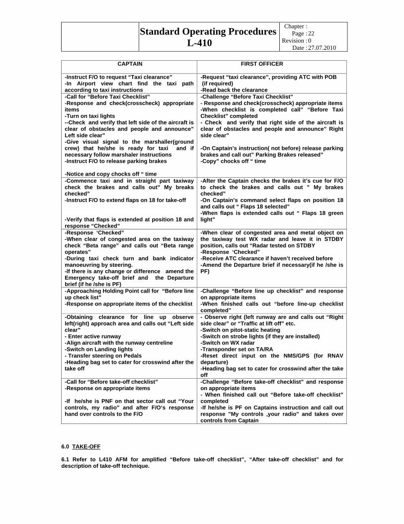
CAPTAIN FIRST OFFICER
-Instruct F/O to request “Taxi clearance” -In Airport view chart find the taxi path according to taxi instructions
-Request “taxi clearance”, providing ATC with POB (if required) -Read back the clearance
-Call for “Before Taxi Checklist” -Response and check(crosscheck) appropriate items -Turn on taxi lights --Check and verify that left side of the aircraft is clear of obstacles and people and announce” Left side clear” -Give visual signal to the marshaller(ground crew) that he/she is ready for taxi and if necessary follow marshaler instructions -Instruct F/O to release parking brakes
-Notice and copy chocks off “ time
-Challenge “Before Taxi Checklist” - Response and check(crosscheck) appropriate items -When checklist is completed call” “Before Taxi Checklist” completed - Check and verify that right side of the aircraft is clear of obstacles and people and announce” Right side clear”
-On Captain’s instruction( not before) release parking brakes and call out” Parking Brakes released” -Copy” chocks off “ time
-Commence taxi and in straight part taxiway check the brakes and calls out” My breaks checked” -Instruct F/O to extend flaps on 18 for take-off
-Verify that flaps is extended at position 18 and response “Checked”
-After the Captain checks the brakes it’s cue for F/O to check the brakes and calls out ” My brakes checked” -On Captain’s command select flaps on position 18 and calls out “ Flaps 18 selected” -When flaps is extended calls out “ Flaps 18 green light”
-Response ‘Checked” -When clear of congested area on the taxiway check “Beta range” and calls out “Beta range operates” -During taxi check turn and bank indicator manoeuvring by steering. -If there is any change or difference amend the Emergency take-off brief and the Departure brief (if he /she is PF)
-When clear of congested area and metal object on the taxiway test WX radar and leave it in STDBY position, calls out “Radar tested on STDBY -Response ‘Checked” -Receive ATC clearance if haven’t received before -Amend the Departure brief if necessary(if he /she is PF)
-Approaching Holding Point call for “Before line up check list” -Response on appropriate items of the checklist
-Challenge “Before line up checklist” and response on appropriate items -When finished calls out “before line-up checklist completed”
-Obtaining clearance for line up observe left(right) approach area and calls out “Left side clear” - Enter active runway -Align aircraft with the runway centreline -Switch on Landing lights - Transfer steering on Pedals -Heading bag set to cater for crosswind after the take off
- Observe right (left runway are and calls out “Right side clear” or “Traffic at lift off” etc. -Switch on pitot-static heating -Switch on strobe lights (if they are installed) -Switch on WX radar -Transponder set on TA/RA -Reset direct input on the NMS/GPS (for RNAV departure) -Heading bag set to cater for crosswind after the take off
-Call for “Before take-off checklist” -Response on appropriate items
-If he/she is PNF on that sector call out “Your controls, my radio” and after F/O‘s response hand over controls to the F/O
-Challenge “Before take-off checklist” and response on appropriate items - When finished call out “Before take-off checklist” completed -If he/she is PF on Captains instruction and call out response ”My controls ,your radio” and takes over controls from Captain
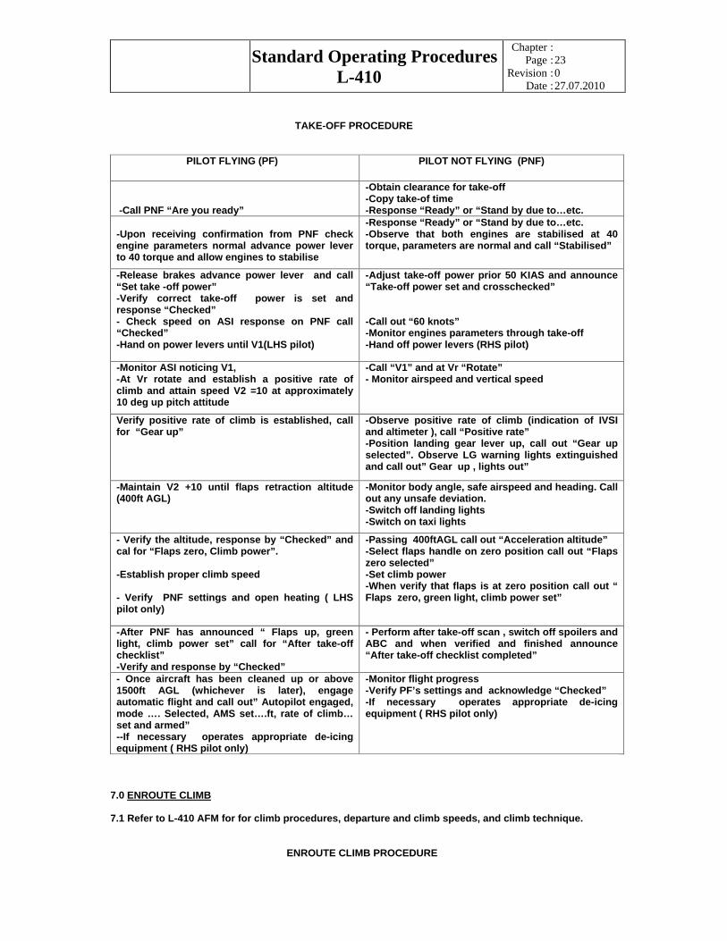
6.0 TAKE-OFF
6.1 Refer to L410 AFM for amplified “Before take-off checklist”, “After take-off checklist” and for description of take-off technique.
Standard Operating Procedures
L-410
Chapter
Page
Revision
Date
::::
23 0 27.07.2010
TAKE-OFF PROCEDURE
PILOT FLYING (PF) PILOT NOT FLYING (PNF)
-Call PNF “Are you ready”
-Obtain clearance for take-off -Copy take-of time -Response “Ready” or “Stand by due to…etc.
-Upon receiving confirmation from PNF check engine parameters normal advance power lever to 40 torque and allow engines to stabilise
-Response “Ready” or “Stand by due to…etc. -Observe that both engines are stabilised at 40 torque, parameters are normal and call “Stabilised”
-Release brakes advance power lever and call “Set take -off power” -Verify correct take-off power is set and response “Checked” - Check speed on ASI response on PNF call “Checked” -Hand on power levers until V1(LHS pilot)
-Adjust take-off power prior 50 KIAS and announce “Take-off power set and crosschecked”
-Call out “60 knots” -Monitor engines parameters through take-off -Hand off power levers (RHS pilot)
-Monitor ASI noticing V1, -At Vr rotate and establish a positive rate of climb and attain speed V2 =10 at approximately 10 deg up pitch attitude
-Call “V1” and at Vr “Rotate” - Monitor airspeed and vertical speed
Verify positive rate of climb is established, call for “Gear up”
-Observe positive rate of climb (indication of IVSI and altimeter ), call “Positive rate” -Position landing gear lever up, call out “Gear up selected”. Observe LG warning lights extinguished and call out” Gear up , lights out”
-Maintain V2 +10 until flaps retraction altitude (400ft AGL)
-Monitor body angle, safe airspeed and heading. Call out any unsafe deviation. -Switch off landing lights -Switch on taxi lights
- Verify the altitude, response by “Checked” and cal for “Flaps zero, Climb power”.
-Establish proper climb speed
- Verify PNF settings and open heating ( LHS pilot only)
-Passing 400ftAGL call out “Acceleration altitude” -Select flaps handle on zero position call out “Flaps zero selected” -Set climb power -When verify that flaps is at zero position call out “ Flaps zero, green light, climb power set”
-After PNF has announced “ Flaps up, green light, climb power set” call for “After take-off checklist” -Verify and response by “Checked”
- Perform after take-off scan , switch off spoilers and ABC and when verified and finished announce “After take-off checklist completed”
- Once aircraft has been cleaned up or above 1500ft AGL (whichever is later), engage automatic flight and call out” Autopilot engaged, mode …. Selected, AMS set….ft, rate of climb… set and armed” --If necessary operates appropriate de-icing equipment ( RHS pilot only)
-Monitor flight progress -Verify PF’s settings and acknowledge “Checked” -If necessary operates appropriate de-icing equipment ( RHS pilot only)
7.0 ENROUTE CLIMB
7.1 Refer to L-410 AFM for for climb procedures, departure and climb speeds, and climb technique.
ENROUTE CLIMB PROCEDURE

Standard Operating Procedures
L-410
Chapter
Page
Revision
Date
::::
24 0 27.07.2010
PILOT FLYING (PF) PILOT NOT FLYING (PNF)
-Maintain two engines climb speed 135KIAS -Monitor terrain clearance -Ensure engines parameter-limits are not exceeded
-Acknowledge “Checked” -Call out every 5000ft passing altitude -Monitor operating systems and fuel usage
-Set 1013 and acknowledge “ 1013 set” -Check altimeter difference and announce e.g. “ +50ft” or “ the same” etc.
-Passing transition altitude call “Transition, altimeter reset”. -Set 1013mb and announce “1013 set, passing FL..”
-Radio altimeter set at 2000 ft -Verify and acknowledge “Checked”
-Passing 10 000ft or FL 100 : *Switch of Auto feather” *Switch of Taxi lights (day) *Switch off “Fasten seat belt” *Radio altimeter set at 2000 ft -Call out “ 10 000 ft check completed”
-Verify and acknowledge “Checked”
-Verify and acknowledge “Checked”
-Verify and acknowledge “Checked”
-1000ft prior to TOC call out “1000 ft to level off AMS armed” -When autopilot captures selected FL( indicated in AMS screen) call out “ Altitude captured” - If aircraft is manually flown 300 ft before assigned FL call out ”300ft to level off” -When autopilot level off the aircraft call out “ Altitude hold” - If aircraft is manually flown reaching assigned FL call out “FL…. Level off”
-Verify and acknowledge “Checked” -When autopilot captures selected FL( indicated in AMS screen) call out “ Altitude captured”
-Call out cruise FL on both altimeters and in AMS screen
8.0 CRUISE
8.1 Refer to L-410 AFM for amplified “Cruise checklist”, procedure, cruise speeds and technique.
CRUISE PROCEDURE
9.0 DESCENT-APPROACH
PILOT FLYING (PF) PILOT NOT FLYING (PNF)
- In level flight maintain climb power until reaching cruise speed then call for “Cruise power” and “Cruise checklist”
-Switch off taxi lights(night) -Set cruise power -Announce “ Cruise checklist completed”
Specific duties:
-Navigation and track keeping -Decide selection of navigational aids -Weather monitoring and avoidance -Fuel monitoring -Systems monitoring
Specific duties:
-SITA/ Flight star CFP logging -Radio communication -Fuel management -Systems management -Track monitoring -Weather monitoring

Standard Operating Procedures
L-410
Chapter
Page
Revision
Date
::::
25 0 27.07.2010
9.1 Refer to L-410 UVP-e AFM for amplified “Descent” and “Approach checklist” descent speeds and technique.
9.2 It is of paramount importance that flight crew manage the aircraft energy (Efficient Energy Management), so PF should adjust TOD profile appropriately and be within manageable descent profile all the time .The descent profile must be monitored continuously and adjusted as early as practicable so as to avoid ending up too low/slow on approach (fuel economy reason ) or too high/fast ( un-stabilised approach). DESCENT AND APPROACH PROCEDURES
PILOT FLYING (PF) PILOT NOT FLYING (PNF)
-Calculate TOD for the most efficient energy management. -Receive PNF’s report about destination and diversion weather -Verify landing data card
-Obtain destination and diversion weather as soon as practicable. -Anticipate time of PF briefing ( approximately 50 Nm before TOD) -Prepare landing data card
-Complete Descent-Approach briefing before TOD (format is given in Chap.1.5.4) -Verify all radio and navigational settings an acknowledge by “Checked” -Instruct PNF to request descent 5 Nm before TOD
-Set radio and navigational aids according to PF’s briefing and call out setting
-When instructed request descent clearance
-At TOD or as instructed by ATC, commence descent select and arm autopilot and AMS in accordance with the clearance and call out all settings.
-Switch on taxi lights(night) -Verify PF’s settings and acknowledge “Checked
-Stabilised on descent call for” Descent checklist” -Response on appropriate items
- Challenge “Descent checklist”, response appropriate items and when finish announce “Descent checklist completed
-Acknowledge PNF’s altitude call -Call passing every 5000ft
-Verify and acknowledge “Checked”
-Passing 10 000ft : *Switch on taxi lights (day) *Switch on “Auto feather” *Switch on “Fasten seat belt” -Announce “10 000ft check completed”
PILOT FLYING (PF) PILOT NOT FLYING (PNF)
-Set QNH and acknowledge “10.. set” -Check altimeter difference and announce e.g. “ +50ft” or “ the same” etc.
-Passing transition level call out “Transition altimeter reset -Set 10...mb and announce “1013 set, passing altitude ….”
-Call for “Approach checklist” -Response on appropriate items
-Perform , challenge and response appropriate items from the checklist -Switch on ABC and spoilers -When finished announce “Approach checklist completed”
10.0 LANDING
10.1 Refer to L410 UVP-E AFM for amplified “Landing checklist”, landing speeds, approach and landing technique.
10.2 Landing with flaps 42 will not be used in our regular operations, except in special cases, when it will be specially discussed and briefed. It will not be taken in consideration in this SOP.

Standard Operating Procedures
L-410
Chapter
Page
Revision
Date
::::
26 0 27.07.2010
LANDING PROCEDURES
PILOT FLYING (PF) PILOT NOT FLYING (PNF)
-Set up approach aids as early as possible -Set up and identify approach aids as early as possible
-Prior to intercept , ensure both VHF NAV frequencies are selected correctly for the appropriate instrument letdown -Arm the FD, AMS (LHS pilot only), and autopilot for the approach and (AP must be in HDG mode), as soon as receive clearance for the approach and set aircraft on intercept heading for the approach.
-Advice PF when both VHF NAV frequencies are selected , tuned and identified
-Arm the FD (LHS pilot only) and verify that PF has properly armed the autopilot.
-Standard callouts (see Chap 1.10.0) -Standard callouts (see Chap 1.10.0) -Call for gear down in accordance with the landing approach requirements -Verify that LG is extended and locked and acknowledge “Checked”
-Check LG extension speed and position LG lever in Down position and call out “Gear down selected” -When LG is extended and locked by indication call out “Gear down three green
-Call for flaps 18 -Close heating (LHS pilot only) and call out “Heating closed - Verify and acknowledge “Checked”
-Instruct PNF to set and call out “Maximum RPM”
-Lower flaps as required and call out “Flaps 18 selected” - Verify and acknowledge “Checked” -When flaps is extended on 18 call out “Flaps 18,green light” -Switch off: *Wx radar *Airframe de-icing(if it was on) -Set propeller lever full forward on maximum RPM And call out “ Maximum RPM set” -Callout any deviation of a stabilised approach
-Call for “Before landing checklist” -Response on appropriate items from the checklist
-Challenge “Before landing checklist” and response appropriate items -When it is finished announce “Before landing checklist completed”
-If at minima any of references is visible, disconnect autopilot, confirm visual contact by call out “Visual landing” continue approach and land the aircraft. - When receive call out “ Go Around “ it is mandatory to execute go around procedure and acknowledge by call out “ Going Around, disengage autopilot and commence GA.
-Call out “Hundred to minima” -Call out “ Minima runway in sight” or “Minima runway approach lights in sight” etc -If at minima there is no visual references call out “Minima runway not in sight-Go Around” or “Minima negative contact fly horizontally to Missed Approach Point” and if then is no visual references call out “Go Around
11.0 LANDING ROLL
11.1 Refer to L-410 UVP-E AFM for amplified “After Landing Checklist”.
LANDING ROLL PROCEDURE

Standard Operating Procedures
L-410
Chapter
Page
Revision
Date
::::
27 0 27.07.2010
PILOT FLYING (PF) PILOT NOT FLYING (PNF)
-Over the landing threshold, power levers idle before touch down -At touch down deploy spoilers -Operate reverse power initially to maximum then within the “Beta range”(Do NOT apply reverse until firmly on the ground with all wheels)
-Verify that spoilers are deployed , if not call out “Spoilers” -Observe reverse lights illuminate, monitor reverse power operation -Advise PF about any abnormality
-At 50 knots, the primary mode of slowing down is now being transferred from the reverse power to the brakes.
-As the aircraft decelerates call out “ 50 knots” -Monitor brake pressure
-At normal taxi speed , the power lever should be gradually returned form “beta range” to normal idle
-Observe reverse lights extinguish.
CAPTAIN FIRST OFFICER
-At normal taxi speed call out “”My controls ,your radio” and take over controls (if RHS pilot was PF)
-Acknowledge “Your controls, my radio”(if he/she was PF
- Transfer steering control from pedals to manual and call out “Manual steering”. - When vacate the runway switch of landing lights , turn on taxi lights and call “After Landing Checklist”
-It is cue for RHS pilot to perform after landing checklist, check and response silently all items and when finished announce “After landing Checklist” completed - Once clear of active runway, establish communication with ground for taxi instruction
-Taxi towards parking apron and bay/stand. Ensure that at all times. The given taxi instructions are being complied with. -Acknowledge “Visual with marshaller”.
-Look out for ground collision hazards and provide correct taxiway guidance for LHS pilot towards the approved parking bay. -When visual with marshaller, call out “Marshaller in-sight”
12.0 PARK AND SHUTDOWN
12.1 Refer to L-410 UVP-E AFM for parking procedure and amplified “Shutdown Checklist”
SHUTDOWN PROCEDURE
CAPTAIN FIRST OFFICER
-Verify park brake is set, under pressure and acknowledge “Checked”. -Receive signal from marshaller(ground crew) that chocks are in place - Fuel –start cocks cut-off and when propellers stop rotation , fuel pumps off -Beacon off
-Set park brake and pump the pressure. Call out “Park brake set”
-Note shutdown time
- Call for “Shutdown checklist” -Check and response on appropriate items
-Perform ,scan and response on appropriate items from “Shutdown Checklist”
-Instruct F/O to disarm and open entry door -Open entry and main, cargo door Set: -HSI course on next anticipated SIS outbound track and HDG bug on expected departure runway heading -RA bug on 400 ft(acceleration height) -Position elevator trimmer to zero
-HSI course on next anticipated SIS outbound track and HDG bug on expected departure runway heading -RA bug on 400 ft(acceleration height) -Transponder code 2000 -AMS set to next expected altitude -Turnoff all instrument lights
TERMINATING FLIGHT ADMINISTRATIVE DUTY
CAPTAIN FIRST OFFICER
-Return Jeppesen charts to the route manual -Ensure all entries by G/E in the technical log are
-Return Jeppesen charts to the route manual -Complete Voyage report
Standard Operating Procedures
L-410
Chapter
Page
Revision
Date
::::
28 0 27.07.2010
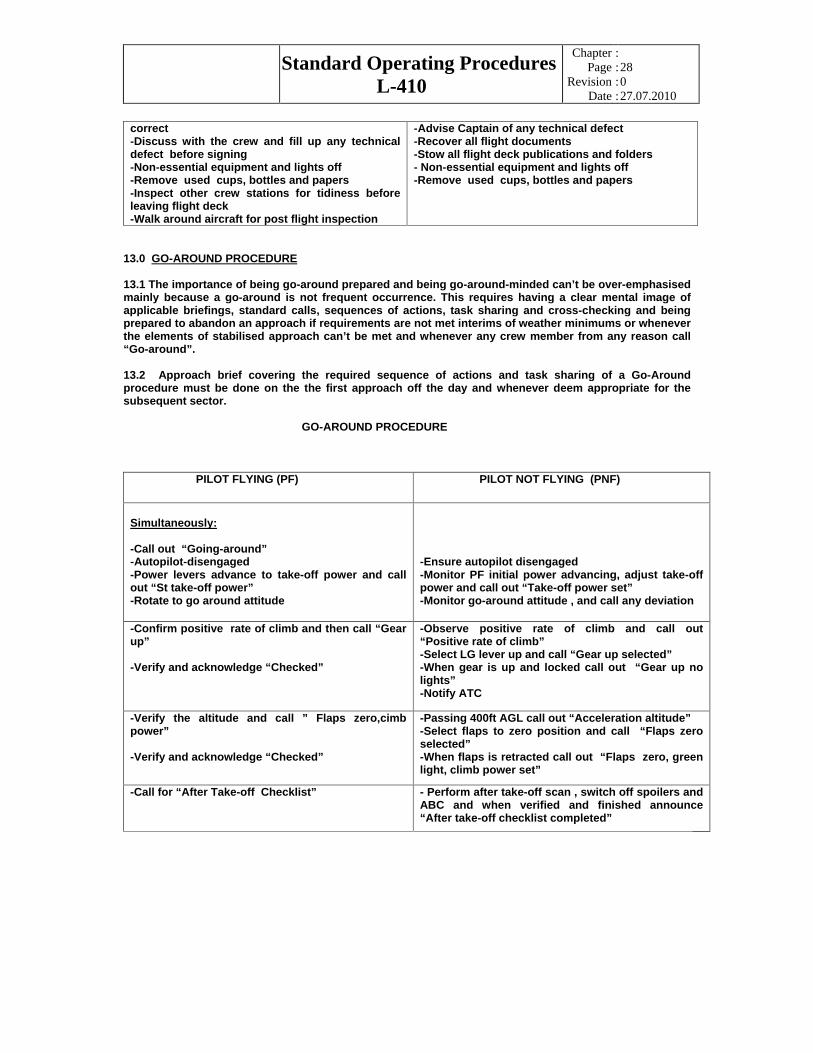
correct -Discuss with the crew and fill up any technical defect before signing -Non-essential equipment and lights off -Remove used cups, bottles and papers -Inspect other crew stations for tidiness before leaving flight deck -Walk around aircraft for post flight inspection
-Advise Captain of any technical defect -Recover all flight documents -Stow all flight deck publications and folders - Non-essential equipment and lights off -Remove used cups, bottles and papers
13.0 GO-AROUND PROCEDURE
13.1 The importance of being go-around prepared and being go-around-minded can’t be over-emphasised mainly because a go-around is not frequent occurrence. This requires having a clear mental image of applicable briefings, standard calls, sequences of actions, task sharing and cross-checking and being prepared to abandon an approach if requirements are not met interims of weather minimums or whenever the elements of stabilised approach can’t be met and whenever any crew member from any reason call “Go-around”.
13.2 Approach brief covering the required sequence of actions and task sharing of a Go-Around procedure must be done on the the first approach off the day and whenever deem appropriate for the subsequent sector.
GO-AROUND PROCEDURE
PILOT FLYING (PF) PILOT NOT FLYING (PNF)
Simultaneously:
-Call out “Going-around” -Autopilot-disengaged -Power levers advance to take-off power and call out “St take-off power” -Rotate to go around attitude
-Ensure autopilot disengaged -Monitor PF initial power advancing, adjust take-off power and call out “Take-off power set” -Monitor go-around attitude , and call any deviation
-Confirm positive rate of climb and then call “Gear up”
-Verify and acknowledge “Checked”
-Observe positive rate of climb and call out “Positive rate of climb” -Select LG lever up and call “Gear up selected” -When gear is up and locked call out “Gear up no lights” -Notify ATC
-Verify the altitude and call ” Flaps zero,cimb power”
-Verify and acknowledge “Checked”
-Passing 400ft AGL call out “Acceleration altitude” -Select flaps to zero position and call “Flaps zero selected” -When flaps is retracted call out “Flaps zero, green light, climb power set”
-Call for “After Take-off Checklist” - Perform after take-off scan , switch off spoilers and ABC and when verified and finished announce “After take-off checklist completed”
Standard Operating Procedures
L-410
Chapter
Page
Revision
Date
::::
29 0 27.07.2010
CHAPTER 3
AIRCRAFT OPERATIONS
ABNORMAL AND EMERGENCY
PROCRDURES

Standard Operating Procedures
L-410
Chapter
Page
Revision
Date
::::
30 0 27.07.2010
1.0 INTRODUCTION
1.1 “Abnormal and Emergency “procedures contained in “LET” Quick Reference Handbook (QRH) is for immediate reference for the flight crew. Amplified description of these procedures can be obtained from the L-410 Aircraft Flight Manual.
1.2 Crewmembers are expected to recognise the differences between Abnormal and Emergency procedures.
2.0 CHECKLIST PROCEDURES
2.1 A crewmember detecting an existing or impending emergency or any abnormal condition requiring alternate operations will immediately inform PF.
2.2 The PF will take the necessary action to establish and/or maintain control of the airplane and call for the appropriate checklist .On his/her command the PNF will refer to the QRH for the checklist and read aloud, in sequence of each checklist item including its respective response. Following the reading of a checklist, the PNF will ensure the designated PF and PNF items are accomplished accordingly and then call out the response.
2.3 First Officer when acting as PF will continue to exercise decision making during any impending emergency or abnormal operations. Without compromising safety, the Captain may positively take-over control and thereby reverting to PF role during any phase of flight. In which case the First Officer will immediately assume the roll of PNF.
2.4 Crewmembers will silence any aural warning as soon as the cause of the warning is recognised. The silencing of aural warning is normal crew action and is not listed in any procedure.
2.5 Oxygen masks and goggles should be donned and communication established whenever situation warrants it and this is not limited to the recall procedures.
2.6 Crewmembers will check circuit breakers and test lights when appropriate, what is normal crew action and is not listed in Abnormal and Emergency procedures unless there is specific requirement. One reset of any tripped circuit breaker may be attempted after a cooling period of two minutes. If the circuit breaker re-trips, don’t attempt another reset. Do not reset any tripped fuel pump circuit breaker.
2.7 Upon completion of a checklist, PNF (F/O on ground) will announce “XXXX Checklist completed”
3.0 ABNORMAL AND EMERGENCY PROCEDURES
3.1 Emergency procedures in the QRH are the checklists with red shaded background. These procedures contain Recall (marked with red boxed M) action items, Reference items and review items.
3.2 Abnormal procedures contain only the Reference and review items.
Standard Operating Procedures
L-410
Chapter
Page
Revision
Date
::::
31 0 27.07.2010
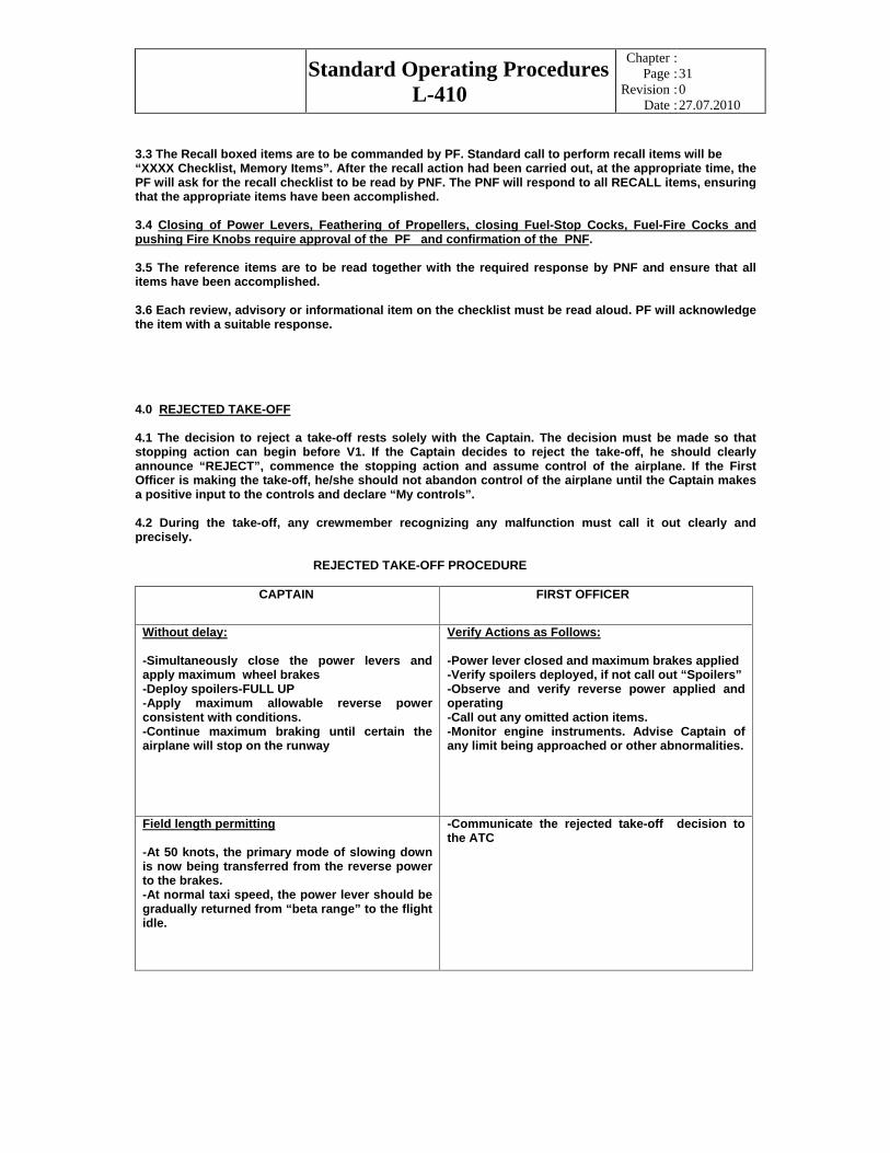
3.3 The Recall boxed items are to be commanded by PF. Standard call to perform recall items will be “XXXX Checklist, Memory Items”. After the recall action had been carried out, at the appropriate time, the PF will ask for the recall checklist to be read by PNF. The PNF will respond to all RECALL items, ensuring that the appropriate items have been accomplished.
3.4 Closing of Power Levers, Feathering of Propellers, closing Fuel-Stop Cocks, Fuel-Fire Cocks and pushing Fire Knobs require approval of the PF and confirmation of the PNF.
3.5 The reference items are to be read together with the required response by PNF and ensure that all items have been accomplished.
3.6 Each review, advisory or informational item on the checklist must be read aloud. PF will acknowledge the item with a suitable response.
4.0 REJECTED TAKE-OFF
4.1 The decision to reject a take-off rests solely with the Captain. The decision must be made so that stopping action can begin before V1. If the Captain decides to reject the take-off, he should clearly announce “REJECT”, commence the stopping action and assume control of the airplane. If the First Officer is making the take-off, he/she should not abandon control of the airplane until the Captain makes a positive input to the controls and declare “My controls”.
4.2 During the take-off, any crewmember recognizing any malfunction must call it out clearly and precisely.
REJECTED TAKE-OFF PROCEDURE
CAPTAIN FIRST OFFICER
Without delay:
-Simultaneously close the power levers and apply maximum wheel brakes -Deploy spoilers-FULL UP -Apply maximum allowable reverse power consistent with conditions. -Continue maximum braking until certain the airplane will stop on the runway
Verify Actions as Follows:
-Power lever closed and maximum brakes applied -Verify spoilers deployed, if not call out “Spoilers” -Observe and verify reverse power applied and operating -Call out any omitted action items. -Monitor engine instruments. Advise Captain of any limit being approached or other abnormalities.
Field length permitting
-At 50 knots, the primary mode of slowing down is now being transferred from the reverse power to the brakes. -At normal taxi speed, the power lever should be gradually returned from “beta range” to the flight idle.
-Communicate the rejected take-off decision to the ATC
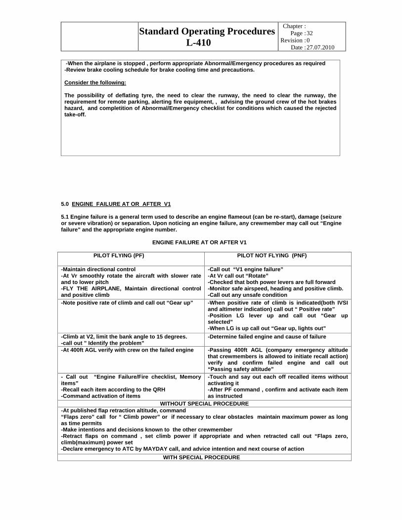
Standard Operating Procedures
L-410
Chapter
Page
Revision
Date
::::
32 0 27.07.2010
-When the airplane is stopped , perform appropriate Abnormal/Emergency procedures as required -Review brake cooling schedule for brake cooling time and precautions.
Consider the following:
The possibility of deflating tyre, the need to clear the runway, the need to clear the runway, the requirement for remote parking, alerting fire equipment, , advising the ground crew of the hot brakes hazard, and completition of Abnormal/Emergency checklist for conditions which caused the rejected take-off.
5.0 ENGINE FAILURE AT OR AFTER V1
5.1 Engine failure is a general term used to describe an engine flameout (can be re-start), damage (seizure or severe vibration) or separation. Upon noticing an engine failure, any crewmember may call out “Engine failure” and the appropriate engine number.
ENGINE FAILURE AT OR AFTER V1
PILOT FLYING (PF) PILOT NOT FLYING (PNF)
-Maintain directional control -At Vr smoothly rotate the aircraft with slower rate and to lower pitch -FLY THE AIRPLANE, Maintain directional control and positive climb
-Call out “V1 engine failure” -At Vr call out “Rotate” -Checked that both power levers are full forward -Monitor safe airspeed, heading and positive climb. -Call out any unsafe condition
-Note positive rate of climb and call out “Gear up” -When positive rate of climb is indicated(both IVSI and altimeter indication) call out “ Positive rate” -Position LG lever up and call out “Gear up selected” -When LG is up call out “Gear up, lights out”
-Climb at V2, limit the bank angle to 15 degrees. -call out ” Identify the problem”
-Determine failed engine and cause of failure
-At 400ft AGL verify with crew on the failed engine -Passing 400ft AGL (company emergency altitude that crewmembers is allowed to initiate recall action) verify and confirm failed engine and call out “Passing safety altitude”
- Call out “Engine Failure/Fire checklist, Memory items” -Recall each item according to the QRH -Command activation of items
-Touch and say out each off recalled items without activating it -After PF command , confirm and activate each item as instructed
WITHOUT SPECIAL PROCEDURE -At published flap retraction altitude, command “Flaps zero” call for “ Climb power” or if necessary to clear obstacles maintain maximum power as long as time permits -Make intentions and decisions known to the other crewmember -Retract flaps on command , set climb power if appropriate and when retracted call out “Flaps zero, climb(maximum) power set -Declare emergency to ATC by MAYDAY call, and advice intention and next course of action
WITH SPECIAL PROCEDURE

Standard Operating Procedures
L-410
Chapter
Page
Revision
Date
::::
33 0 27.07.2010
-Execute Special procedure if required (if unable to follow SO ask PNF to advise ATC and request immediate assistance.
-Monitor and ensure that PF is executing the SP correctly. At SP designated points, advise the PF to execute emergency procedure turn if necessary. MAYDAY call and inform ATC of the special procedure or if unable to comply with SP. -Monitor 5 min. maximum power limit
-Roll out on SP heading first before retracting flaps(not below flaps retraction altitude)
-retract flaps as commanded by PF
-Call for “Climb power” -Set climb power and call “Climb power set” - Continue with the SP -Above 1500ft above airfield, it may be turned around to land, climb to conduct instrument approach or divert to another airfield for landing. Make intentions known to the other crewmember.
-Provide appropriate support accordingly
-Call for appropriate ‘Emergency’ checklist
-Call for “After take-off checklist”
-Perform the checklist ,ensure items are carried out and respond on the all items in the checklist -Perform and challenge the checklist, when finished call out “After take-off checklist” completed
-Consider engine re-start if it was an engine flame-out
-Check engine status and advise PF
6.0 RESPONSE TO EGPWS ALERTS
6.1 The recommended response to EGPWS (Enhanced Ground Proximity Warning System) alerts is as follows:
a. CAUTION ALERT
-Stop any descent or climb as necessary to eliminate alert -Analyse all available instruments and information to determine the best course of action. -Advice ATC if necessary.
b. WARNING ALERT
-PF aggressively position power levers to the maximum available power as determinate by emergency need. The PNF should adjust power and ensure that TO/GA power is set. -If engaged, disengaged the autopilot and smoothly, but aggressively increase pitch to the maximum permissible for that configuration, to obtain maximum climb performance. -Do not change the aircraft configuration and continue climbing until warning is eliminated and safe flight is assured. -Advice ATC of the situation
6.2 Note:
Climbing is only recommended response unless operating in visual conditions and/or pilot determinates, based on all available information that turning in addition to the climb is the safest course of the action.
//

This document was created with Win2PDF available at http://www.win2pdf.com.The unregistered version of Win2PDF is for evaluation or non-commercial use only.This page will not be added after purchasing Win2PDF.